
Download the digital catalog CATALOG OF PRODUCTS
PRODUCT GROUP
3 RITZ FERRAMENTAS A Grounding Equipment . . . . . . . . . . . . . . 023 B Hand Sticks, Hot Sticks and Universal Tools 085 C Cover-Up and Insulating Rubber. . . . . . . . 125 D Tool Repair and Storage 149 E Ladders, Platforms and Insulating Scaffold . . . . . . . . . . . . . . . . . 159 F Load Lifting Tools and Acessories . . . . . . . 189 G Conductor Support Equipment 213 H Bare-Hand Equipment . . . . . . . . . . . . . . 273 I Instruments . . . . . . . . . . . . . . . . . . . . . 281 J Temporary Jumpers . . . . . . . . . . . . . . . . 295 L Daylight Warning Spheres 315 rev. 12/2023 Introduction 005 About Us 007 Preservation and Handling of Hot Line Tools 008 Basic Maintenance of Hot Line Tools. . . . . . . . . 008 Characteristics of Hot Line Tools . . . . . . . . . . . 009 Using Hot Line Tools . . . . . . . . . . . . . . . . . . . 009 Glossary . . . . . . . . . . . . . . . . . . . . . . . . . . . 010 Reference Index . . . . . . . . . . . . . . . . . . . . . . 013
INTRODUCTION
PRECAUTIONS FOR HOT LINE TOOLS
The hot line tools described in this catalog must be handled, installed, and stored only by trained personnel who are familiar with the operating procedures and in compliance with applicable safety standards.
The information contained in this catalog and any other information in the instruction manuals shall under no circumstances replace proper training and experience in safety procedures. In addition, they do not cover all details on the tools, nor cover every possible situation concerning tool installation, operation, and maintenance
For further information or special requests not included in this catalog, Ritz should be contacted to assist in developing the most viable solution.
Ritz is continually looking for ways to Ferramentas improve its products and services. Therefore, the information in this catalog may be changed without prior notice, always in view of the total safety of electricians involved in the maintenance activities in electrical systems
HOT LINE WORKING METHODS
The great need to avoid undesirable power maintenance shutdowns required the development of safe techniques and practices for uninterrupted power supply, without negatively affecting generation, transmission, and distribution utilities Not only financially, but also regarding how these utilities are seen by their consumers.
The numberless services to be performed in different voltage classes and different types of electrical installations, such as transmission lines, substations and distribution networks, have encouraged the development of tools, as well as unique and situationspecific working methods, depending on the type and location of the tasks to be performed and even the criteria defined by each utility.
Now the electrical system has three hot line working methods that can be applied in many voltage classes, provided electrician teams are properly trained and have proper tools, personal protective equipment (PPE), and collective protective equipment (CPE)
1° METHOD - HOT STICK METHOD
In this method, the first to be developed, the electrician performs operations using tools attached to the end of a insulating stick This method is designed for work on all voltage classes
For voltages up to 69 kV, where phase distances are shorter, conductors are removed from their original position by means of support poles, clamps etc.
The entire hot line toolkit is designed to make it easier for electricians to move around structures with total safety.
In this method the electrician must strictly observe the phase-to-phase and phase-phase minimum safety distance according to the table.
The recommended safety distances in this table are in accordance with OSHA publication on 01/31/1994.
5 RITZ FERRAMENTAS INTRODUCTION
Rated Voltage (kV) Phase-ground distance (m) Phase-phase distance (m) 0.05 a 1.0 Avoid contact Avoid contact 1.1 a 15 0.64 0.66 15.1 a 36 0.72 0.77 36.1 a 46 0.77 0.85 46.1 a 72.5 0.90 1.05 72.6 a 121 0.95 1.29 138 a 145 1.09 1.50 161 a 169 1.22 1.71 230 a 242 1.59 2.27 245 a 326 2.59 3.80 500 a 550 3.42 5.50 765 a 800 4.53 7.91
2° METHOD - RUBBER GLOVE METHOD
This method comprises of protecting the electrician with gloves and appropriate insulating sleeves (PPE), positioned on a platform, scaffold, ladder, or man basket, performing the services with protected hands.
The entire work area is also protected with insulating covers (CPE) and, during the tasks, the space strictly necessary for operation is uncovered. This rules out the chances of electricians or work components (conductors, tools) touching or approaching two points of different potentials, causing a short circuit.
This method is only used for distribution networks and substations with voltages up to 35 kV
3° METHOD - BAREHAND METHOD
The purpose of this method is to allow for greater maintenance resources, especially on high to ultrahigh voltage transmission lines where safety distances are greater, as well as substations of 60 kV and more.
Barehand work is based on the Faraday Cage principle and consists of direct contact of the electrician with the energized conductor
To protect against electric field effects, the electrician wears a conductive suit over his/her body, leaving only part of his/her face uncovered
When near energized conductors, the electrician connects this suit to a conductor, and then it will be at the same potential as the installation.
For insulating protection and locomotion of the earth potential to the energized installation potential, Ritz currently has several insulating equipment for each type of installation, such as ladders, chairs, insulating extensions, scaffolding, and others.
Before each use, these equipments must be submitted to voltage tests, using the energized conductor at hand as voltage source and measuring the leakage current must be monitored by a micro ammeter - Micro-Tester (RC402-0288) - installed between the bottom end of the equipment and the ground point, to check its insulating conditions in accordance with the leakage current values established by standard.
For field tests of insulating equipment, using a portable electric pole tester (Ritz Tester) is also recommended as another important certification measure of insulating conditions of this equipment before each use
As with the Hot-Stick Work Method, the Barehand Work Method requires strict observance of phaseground and phase-phase safety distances, especially in substation interventions where these distances are reduced.
6 RITZ FERRAMENTAS
INTRODUCTION
ABOUT US
Ritz Ferramentas has specialized for over 55 years in the design and manufacture of tools and equipment for maintenance work on de-energized and energized electrical systems We have a complete portfolio of tools for maintenance work on hot lines up to 800 kV AC and DC for work on electrical systems in contact, distance and potential methods, meeting Brazilian, international and ISO 9001 standards
Pioneer in the manufacture of hot line tools in Brazil, it developed its first tubes reinforced with fiberglass for maintenance in energized networks in 1968, with the manufacture of the so-called Hot Sticks, as it already had a wide knowledge of this technology in the manufacture of insulating parts for application in small oil volume circuit breakers. In 1971, Ritz produced the first complete set of tools for maintenance on energized networks
Between 1973 and 1989, the association with A.B Chance Company, world leader in the segment. The association generated an exchange of know-how and process innovation, making Ritz recognized worldwide for its quality, safety, reliability and excellence
In 2011, another new stage began for the company, with the acquisition by the North American multinational Terex. This provided an evolution and improvement in processes, methodologies, layout, technology, safety, skills, results and the conquest of new international markets.
In 2021, in line with the tradition and reference of the Ritz brand, the shareholding control of the company passed into the hands of a company formed by a group of managers from the predecessor Ritz Ferramentas, maintaining and strengthening the commitment to continue the trajectory of development and innovation that are important marks of its legacy.
QUALITY REFERENCE
RITZGLAS® glass fiber reinforced tubes, a Ritz trademark, are internationally recognized for their quality and reliability. RITZGLAS® tubes are subjected to tests based on ASTM F-711 and IEC 60855 standards

RITZGLAS® Insulating Tube, a critical integral part of most Ritz hot line tools, has a core of single-cell polyurethane foam internally, which prevents moisture or dirt from absorbing and condensation. Its external construction consists of highly treated glass fibers arranged in a circumferential and longitudinal direction and impregnated with epoxy resin of a special formulation.
RITZGLAS® tube has high dielectric strength, mechanical strength and low weight, essential characteristics for hot line tools
The orange of the RITZGLAS® pole is suitable for its good visibility in the work areas, considered an additional safety item for the electrician team.
7 RITZ FERRAMENTAS
ABOUT US
PRESERVATION AND HANDLING OF HOT LINE TOOLS
Hot line tools require specific care for their protection in order to keep them available for immediate use. In addition, such care will result in prolonged tool life and consequently increased user safety and confidence.
As a rule, hot line tools should be kept dry. They should never be placed directly on the ground and should be stored in the vehicle or tool cart until the moment of use and then placed on a support (stick rack). Tools may only be placed on previously covered soil with a clean, dry tarpaulin to protect them from direct contact with dust or moisture.
Due to the nature of the application and the variable severity under which hot line tools are subjected, we suggest the following regarding their use condition:
a. Visual inspection before each use;
b Mechanical tests with the application of the rated . load of the tools, with a periodicity to be defined by the user, which should consider the severity of the previous uses;
c Periodic electrical testing as determined by . international standards and NR-10.
Severity means: exposure of tools to excessive load; load imbalance; chemical corrosion by apparent and non-apparent chemical agents; impacts; improper maintenance (no gap treatment; poor lubrication; no replacement of worn components or replacement with components not approved by the manufacturer; localized malfunction in a component that could compromise an entire toolkit etc.); improper storage and packaging for transport and storage etc
BASIC MAINTENANCE OF HOT LINE TOOLS
Hot-sticks under ideal conditions of use, require the following periodic care:
| Cleaning the Hot-sticks
Most impurities are removed by wiping the stick with a dry cloth. If the stick is impregnated with grease, wipe it with a cloth soaked in isopropyl alcohol or EcoThinner that will not leave any residue. After being clean and dry, they are rubbed with a cloth for cleaning sticks, which is actually a cloth impregnated with substance to protect them. Then, the rod is electrically tested using the Ritz Tester pole tester. This should be done to check that all impurities have been removed
| Hot-stick repair
The gloss restorer should be applied only when it is evident that the coating film is in poor condition. Before applying the gloss restorer, dry the stick Then use a fine sandpaper to remove the old gloss restorer The stick should be cleaned again using the solvent and then dried with a clean cloth before gloss restorer application.
| Rupture repair
If more than superficial damage is identified the rupture restorer may be used to fill the damaged area. Then use a fine sandpaper to remove excess restorer fluid. To use cracks and shine restorers, refer to our Stick and Pole Recovery Manual.
8 RITZ FERRAMENTAS
PRESERVATION AND HANDLING
CHARACTERISTICS OF HOT LINE TOOLS
Hot line tools consist primarily of RITZGLAS® poles and metal parts in special aluminum and bronze alloys. Given the nature of their application, where safety standards are implicitly contained in the working standards themselves, these tools are manufactured under strict quality control, from raw material selection to final reception testing
RITZGLAS® poles are electrically tested during manufacture with 100 kV every 30 cm in accordance with ASTM F-711.
The aluminum parts are heat treated under strict temperature control in order to preserve the physical properties of the basic material as much as possible
No new type of tool is available to the market without type testing to ensure its constructive and operational design characteristics.
IMPORTANT
Maintenance of hot line tools should be treated as a critical process and manufacturer recommendations must be strictly followed.
USING HOT LINE TOOLS
Prior to each use, hot line tools must be visually inspected and electrically tested, which can be done by the user. Before being carried to the electricians on the structure, the tools should be cleaned using a dry cloth and then a stick cleaning cloth. During these cleaning operations, a visual inspection of the metal and insulating parts can be carried out
9 RITZ FERRAMENTAS HOT LINE TOOLS
GLOSSARY
For the better understanding of the reader about the definitions, units of measure, symbols, abbreviations, and keywords addressed in this catalog, we present a brief description of their meanings
DEFINITIONS
| Extra-strengh laminated aluminum
Aluminum alloy plates used in the construction of some yoke models to make them light and sturdy. These yokes are characterized by their construction with plain plates construction
| Jaws Opening Capacity
Limit measures (minimum and maximum) adopted for closing and opening the grounding clamps and some insulating poles, compatible with the cable and conductor that will be used sizes
| Rated Current Capacity
Current withstand unit of an electrical conductor during a given operating time.
In our case, the cables used in temporary grounding and hot line jumpers
| Work Load Capacity
Maximum workload value set for hot line tools (defined in daN).
The values for these loads are specified in this catalog.
| Balanced Maximum Load
When tensile forces or loads are evenly distributed over the lifting equipment.
| Unbalanced Maximum Load
When tensile forces or loads are unevenly distributed over the lifting equipment, thus reducing its rated capacity
| Shear
Application of two forces in opposite directions, converging, with the same direction and perpendicular to the axis of a body, tending to divide it into two parts
| Catenary
Uniform curve assumed by a body (e.g. cable) when suspended by its two ends (pole) and under the sole action of its own weight.
| Work Length
Useful distance between tool coupling points (energized side and de-energized side).
| Insulating Length
Safety distance limit for each hot line tool This length is usually located between the point of contact with the energized part and the electrician's holding point (or de-energized part).
| Total Length
Distance between ends of a hot line tool
| Phase-to-phase distance
Minimum distance between two phases, with different potentials in the same circuit.
| Phase-to-ground distance
Minimum distance between an energized and a deenergized part of an electrical installation.
| Tracking effect
Irreversible degradation caused by the formation of paths that start and develop on the surface of an insulating material, being favorable to electric current conduction through these paths, even when dry
| Structures
Buildings such as towers, poles of wood, concrete or steel to support electricity conductors, so that the electrical power can be transported over long distances
| Bending
Application of perpendicular forces to the axis of a body, which is supported by one or two points.
10 RITZ FERRAMENTAS GLOSSARY
| Faraday's Cage
Physics Principle, developed by Michael Faraday (1791-1867), where inside an enclosed conductive surface the electric field is null. In order to shield and protect the electrician against the effect of an electric field when in contact with the potential, conductive clothing is used.
| Electrical Interventions
Maintenance performed on electrical systems, in order to continue the transmission of electricity through specific procedures and by qualified persons
| Handling
Manually using hot line tools or other instruments.
| Jaw
Moving part of grounding clamps, yokes, or insulating poles for the purpose of securing the conductor or various couplings.
Usually these jaws are driven by turning the clamping screws (for grounding clamps) or the pole itself
| Operate
Using hot line equipment or other instruments in interventions on energized installations, within the procedures and characteristics of each product.
| Low Voltage Networks (LV)
Circuits exceeding 50 volts, equal to or less than 1 kV, between phases or between phases and ground.
| Medium-Voltage Network (MV)
Circuits with voltages above 1 kV to 50 kV, which generally distribute the power received from transmission systems to large, medium, and small consumers
| High Voltage Networks (HV)
Circuits with voltages above 50 kV up to 230 kV, responsible for transporting electricity from production to consumption centers.
| Extra High Voltage Networks (EHV)
Circuits with voltages above 230 kV to 750 kV, also responsible for transporting electricity from production centers to consumption centers, usually over longer distances
| Ultra High Voltage Networks (UHV)
Circuits with voltages above 750 kV, also responsible for transporting electricity from production centers to consumption centers, usually over greater distances.
| Dielectric strength
Higher electric field value of an insulating tool without it becoming a conductor.
This dielectric strength varies from tool to tool, for example: in the case of air, its dielectric strength is about 3.0 kV/mm. Thus, when an electric field in the air exceeds this value, it ceases to be insulating and becomes conductive
| Rated Voltage
Maximum allowable electrical voltage value for work on insulating equipment.
| Traction
Application of forces acting perpendicular to the cross section of a body and with the same direction, but in opposite directions, tending to lengthen it.
| Torsion
Applying a circular force to the end of a body that tends to deform it.
| Torque
A vector quantity defined as the fraction of a force applied to an object, which is effectively used to rotate around an axis or center point, known as a pivot point. As an example, in the grounding clamps, the torque is applied to the clamping screws, whose values are in this catalog and defined in daN.m.
| Thermal treatment
A process by which cast aluminum components and/or parts are subjected to high temperature treatment in order to increase their mechanical strength.
| Use Tools in line
Installing two or more tools sequentially for the purpose of increasing isolation in the intervention. Example: Use of a nylon strap coupled to an insulating pole for hoists and blocks.
11 RITZ FERRAMENTAS GLOSSARY
UNIT OF MEASUREMENT
| Ampere (A)
Electrical current measurement unit that, with an electromotive force of 1 Volt it travels a circuit with a resistance of 1 Ohm.
| AWG
American Wire Gauge, American denomination used for wire gauges (thickness). The standard metric series in mm2 is currently used in Brazil
| CA
Brazilian Identification Unit for bare wire crosssections without steel core. (equivalent to ASC).
| CAA
Brazilian identification unit for steel core aluminum bare wire cross-section (equivalent to ACSR).
| Kcmil ACSR (circular mil)
A circular mil is the area of a circle with a diameter of one thousandth of an inch. This is one of the units adopted for wire or cable cross-sections.
| daN (decaNewtons)
A unit adopted by ABNT for forces exerted on hot line tools. (According to ABNT (Brazilian Technical Standards Association), 1 daN is considered 1 kgf kilogram-force).
| Kilovolt (kV)
Electrical voltage unit equivalent to 1x10³ V
| Volt (V)
Unit of electrical voltage, potential difference or electromotive force. It corresponds to the voltage that, applied over the 1 Ohm resistance, produces the 1 amp current.
SYMBOLS / ABBREVIATIONS
| Ø (diameter)
Geometric figure with same midpoints of parallel strings to designate the circular measurement of a given tool
| ®
Trademark of a product or process of a particular company.
| ATR
Abbreviation used by Ritz to designate Temporary Grounding.
| FLV
Abbreviation used by Ritz to designate hot line Tools
| NBI (Basic Insulation Level)
Value (in kV) that a device must withstand when applying a voltage pulse for a given time without changing its insulating characteristics
| RITZGLAS®
Ritz trademark for the insulating fiberglass pipe, which is a fundamental integral part of most hot line tools
12 RITZ FERRAMENTAS
GLOSSARY
13 RITZ FERRAMENTAS ÍNDICE POR REFERÊNCIA Refer ence Index 1500E 193 3000E. . . . . . . . . 193 51.E07.D20-CE . . . 210 51.E07.D30-CE 210 51.E07.D40-CE . . . 210 51.E07.D50-CE . . . 210 6000E 193 750E . . . . . . . . . 193 ATR00137-1 82 ATR00137-2 . . . . . 82 ATR00137-3 . . . . . 82 ATR00395-8 57 ATR00548-1 . . . . . 30 ATR01726-3 74 ATR01875-1 . . . . . 58 ATR03308-2 . . . . . 67 ATR03318-1 79 ATR03402-1 . . . . . 82 ATR03641-1 . . . . . 80 ATR03653-1 63 ATR03654-2 . . . . . 33 ATR04116-1 78 ATR04514-1 . . . . . 28 ATR04514-2 . . . . . 28 ATR04631-1 38 ATR04694-1 . . . . . 78 ATR08814-1 82 ATR08814-2 . . . . . 82 ATR08814-3 . . . . . 82 ATR08814-4 82 ATR08947-1 . . . . . 64 ATR08968-1 . . . . . 61 ATR08969-1 60 ATR08969-2 . . . . . 60 ATR08969-3 60 ATR08969-4 . . . . . 60 ATR08969-5 60 ATR08969-6 . . . . . 60 ATR08969-7 . . . . . 60 ATR09033-1 64 ATR09729-1 . . . . . 37 ATR09730-1 36 ATR09734-2 35 ATR09734A-2 . . . . 35 ATR09962-1 154 ATR10777-1 . . . . . 70 ATR10994-1 . . . . . 107 ATR11627-1 66 ATR11627-2 . . . . . 73 ATR12407-1 45 ATR12407-2 . . . . . 46 ATR12408-1 . . . . . 48 ATR13036-2 76 ATR13036-8 . . . . . 77 ATR13043-1 31 ATR13047-1 63 ATR13047-2 . . . . . 63 ATR13147-1 60 ATR13151-1 . . . . . 31 ATR13159-1 . . . . . 69 ATR13628-1 63 ATR14442-1 . . . . . 78 ATR14477-1 79 ATR14484-1 . . . . . 154 ATR14484-2 . . . . . 154 ATR15508-2 32 ATR16449-3 . . . . . 73 ATR16843-1 154 ATR16843-2 154 ATR16843-3 . . . . . 154 ATR16843-4 154 ATR16843-5 . . . . . 154 ATR16843-6 154 ATR16843-7 . . . . . 154 ATR17179-2 . . . . . 76 ATR17179-8 77 ATR17184-2 . . . . . 76 ATR17184-8 77 ATR17185-2 76 ATR17185-8 . . . . . 77 ATR17348-1 64 ATR17439-1 . . . . . 29 ATR17439-2 . . . . . 29 ATR17440-2 49 ATR17440-3 . . . . . 50 ATR17440-4 50 ATR17441-1 . . . . . 53 ATR17442-1 . . . . . 54 ATR17454-1 55 ATR17454-2 . . . . . 56 ATR17455-1 47 ATR17456-1 42 ATR17457-1 . . . . . 40 ATR17459-1 65 ATR17460-1 . . . . . 65 ATR17461-1 . . . . . 65 ATR17462-1 65 ATR17572-1 . . . . . 43 ATR17574-1 81 ATR18867-1 . . . . . 78 ATR19357-1 . . . . . 64 ATR19433-1 64 ATR20231-1-1 . . . 51 ATR20232-1-3 52 ATR20763-1 44 ATR21918-2 . . . . . 32 ATR23989-1 58 ATR26446-2 . . . . . 77 ATR26446-3 77 ATR26446-4 . . . . . 77 ATR26446-5 . . . . . 77 ATR26446-6 77 ATR26555-1 . . . . . 81 ATR30260-1 34 ATR30783-1 39 ATR30985-1 . . . . . 187 ATR31691-1 82 COB03333-1 . . . . 136 COB03335-2 . . . . 134 COB04487-1 130 COB04487-2 . . . . 130 COB04487-3 130 COB04487-4 . . . . 130 COB08835-2 . . . . 135 COB10765-1 131 COB11047-1 . . . . 137 COB11050-1 137 COB11051-1 137 COB11147-1 . . . . 137 COB11170-1 137 COB11170-2 . . . . 137 COB11173-1 . . . . 131 COB11173-2 131 COB11176-1 . . . . 130 COB11176-2 130 COB11176-3 . . . . 130 COB11176-4 . . . . 130 COB11400-1 134 COB11612-1 . . . . 138 COB11617-1 139 COB11622-1 139 COB11721-1 . . . . 141 COB13345-1 132 COB13559-1 . . . . 140 Catalog Reference Page Catalog Reference Catalog Reference Catalog Reference Page Page Page
EE/PR-15/10-CN-SM164
EE/PUD-71-CN-SB
14 RITZ FERRAMENTAS ÍNDICE POR REFERÊNCIA Refer ence Index COB14780-1 131 COB14959-1 . . . . 140 COB18644-1 . . . . 141 COB19874-1 140 COB20663-1 . . . . 139 COB20664-1 . . . . 139 COB22404-1 138 COB24863-1 . . . . 141 COB24885-1 141 COB24891-1 . . . . 141 COB26095-1 . . . . 138 COB28494-1 132 COB30064-1 . . . . 137 COB31387-1 136 COB31716-1 . . . . 140 CT 0,05-1. . . . . . . 289 CT 0,07-1 289 CT 5-15. . . . . . . . 289 CT 3,8-36. . . . . . . 289 CT 12-36 289 CT 10-40 . . . . . . . 289 CT 60-240 289 CT 60-440 . . . . . . 289 CTA-35 . . . . . . . . 75 CTC-25 75 CTC-35 . . . . . . . . 75 CTC-50 75 CTC-70 . . . . . . . . 75 CTC-95 . . . . . . . . 75 CT-CC 0,5-5 291 CT-CSU-10-40 . . . 290 CT-CSU-3,8-36/SB . 290 CT-RS/C 2-6 290 CT-RS/C 3,8-36 . . . 290 DMU-15 291 DMU-25 . . . . . . . 291 DMU-36/SB 291 EA/PR-12/PD . . . . 165 EA/PR-15/PD . . . . 165 EA/PR-21/PD 165 EA/PR-27/PD . . . . 165 EA/PR-34/PD 165 EA/PR-40/PD 165 EA/PR-52/PD . . . . 165 EE/LV-108-CN-SB 174 EE/LV-120-CN-SB . 174 EE/LV-96-CN-SB . . 174
EE/PR-12/58-CN-SM164 EE/PR-12/70-CN-SM164 EE/PR-12/82-CN-SM164
EE/PR-15/11-CN-SM164 EE/PR-15/14-CN-SM164 EE/PR-15/95-CN-SM164 EE/PU-35-CN-SB 162 EE/PU-41-CN-SB 162 EE/PU-47-CN-SB . . 162 EE/PU-53-CN-SB 162 EE/PU-59-CN-SB . . 162 EE/PU-65-CN-SB . . 162 EE/PU-71-CN-SB 162 EE/PU-77-CN-SB . . 162
162
. . 162
. . 162
163 EE/PUD-41-CN-SB . 163
163
163
. 163
163
EE/PU-84-CN-SB
EE/PU-90-CN-SB
EE/PU-97-CN-SB
EE/PUD-35-CN-SB
EE/PUD-47-CN-SB
EE/PUD-53-CN-SB
EE/PUD-59-CN-SB
EE/PUD-65-CN-SB
. 163 EE/PUD-77-CN-SB 163 EE/PUD-84-CN-SB . 163 EE/PUD-90-CN-SB . 163 EE/PUD-97-CN-SB 163 ES/LV-28-CN-SB . . 174
174
174
. . 174 ES/PR-8/27-CN-SM 164 ES/PR-8/40-CN-SM 164 ES/PR-8/46-CN-SM 164 ES/PR-8/58-CN-SM 164 ES/PU-29-CN-SB . . 162 ES/PU-32-CN-SB 162 ES/PU-35-CN-SB . . 162 ES/PU-38-CN-SB . . 162 ES/PU-41-CN-SB 162 ES/PU-44-CN-SB . . 162 ES/PU-47-CN-SB 162 ES/PU-50-CN-SB 162 ES/PU-53-CN-SB . . 162 ES/PU-56-CN-SB 162 ES/PU-59-CN-SB . . 162 ES/PU-62-CN-SB . . 162 ES/PU-65-CN-SB 162 ESC15051-1 . . . . . 185 ESC15051-2 185 ESC15051-3 . . . . . 185 ESR11795-1 . . . . . 317 ESR12591-1 317 ESR12963-1 . . . . . 317 ESR19899-1 317 ESR19899-2 317 ESR19899-3 . . . . . 317 ESR19899-4 317 ESR19899-5 . . . . . 317 ESR19899-6 317 ESR19899-7 . . . . . 317 ESR19899-8 . . . . . 317 ESR19900-1 318 ESR19900-2 . . . . . 318 ESR19900-3 318 ESR19900-4 318 ESR19900-5 . . . . . 318 ESR19900-6 318 ESR19900-7 . . . . . 318 ESR19900-8 . . . . . 318 ESR30700-1 316 ESR30700-2 . . . . . 316 ESR30700-3 316 ESR30700-4 . . . . . 316 ESR30700-5 . . . . . 316 ESR30700-6 316 ESR30700-7 . . . . . 316 ESR30700-8 316 ET/LV-28 175 ET/LV-37 . . . . . . . 175 ET/LV-46 175 ET/LV-59 . . . . . . . 175 ETM/01. . . . . . . . 166 ETM/02 166 ETM/03. . . . . . . . 166 ETM/04 166 ETM/05. . . . . . . . 166 ETM/06. . . . . . . . 166 ETM/07 166 ETM/08. . . . . . . . 166 ETM/09 166 ETM/10 166 ETM/11. . . . . . . . 166 ETM/12 166 ETM/13. . . . . . . . 166 Catalog Reference Page Catalog Reference Catalog Reference Catalog Reference Page Page Page
ES/LV-37-CN-SB
ES/LV-46-CN-SB
ES/LV-59-CN-SB
15 RITZ FERRAMENTAS ÍNDICE POR REFERÊNCIA Refer ence Index ETM/14 166 FLV00196-5 . . . . . 201 FLV00714-2 . . . . . 229 FLV01121-4 103 FLV01644-1 . . . . . 201 FLV01852-1 . . . . . 269 FLV02544-1 279 FLV02818-2 . . . . . 115 FLV03102-1 158 FLV03278-3 . . . . . 317 FLV03457-13 . . . . 230 FLV03457-2 269 FLV03457-3 . . . . . 269 FLV03457-5 269 FLV03457-6 . . . . . 269 FLV03460-1 . . . . . 269 FLV03550-2 173 FLV03550-6 . . . . . 173 FLV03550-7 . . . . . 173 FLV03811-3 111 FLV04417-1 . . . . . 142 FLV04417-2 142 FLV04803-1 . . . . . 208 FLV04803-2 . . . . . 208 FLV04803-3 208 FLV05613-1 . . . . . 230 FLV05784-1 307 FLV06052-1 . . . . . 181 FLV06423-1 . . . . . 177 FLV06619-1 210 FLV06619-2 . . . . . 210 FLV06619-3 . . . . . 210 FLV07777-1 203 FLV08257-3 . . . . . 195 FLV08958-1 88 FLV08958-2 . . . . . 88 FLV08958-3 88 FLV08958-4 . . . . . 88 FLV08958-5 . . . . . 88 FLV09012-1 185 FLV09091-1 . . . . . 181 FLV09311-1 119 FLV09429-1 123 FLV10460-1 . . . . . 255 FLV10893-1 203 FLV11042-1 . . . . . 114 FLV11179-1 . . . . . 306 FLV11179-2 306 FLV11179-3 . . . . . 306 FLV11404-1 293 FLV11537-1 . . . . . 252 FLV11554-1 . . . . . 96 FLV11623-1 139 FLV12192-1 . . . . . 246 FLV12240-1 249 FLV12240-2 249 FLV12409-1 . . . . . 310 FLV12563-1 277 FLV13006-1 . . . . . 247 FLV13006-2 . . . . . 247 FLV13006-3 247 FLV13033-1 . . . . . 309 FLV13045-1 309 FLV13130-1 . . . . . 246 FLV13352-1 . . . . . 246 FLV13356-1 246 FLV13780-1 . . . . . 246 FLV13872-1 96 FLV13907-1 119 FLV13916-1 . . . . . 181 FLV13917-1 308 FLV14342-1 . . . . . 185 FLV14342-2 185 FLV14342-3 . . . . . 185 FLV15444-1 . . . . . 186 FLV16054-1 255 FLV16140-1 . . . . . 124 FLV16146-1 124 FLV16148-1 114 FLV16159-1 . . . . . 114 FLV16165-1 113 FLV16193-1 . . . . . 257 FLV16237-1 . . . . . 184 FLV16237-2 184 FLV16238-1 . . . . . 184 FLV16241-1 181 FLV16241-2 . . . . . 181 FLV16241-3 . . . . . 181 FLV16241-4 181 FLV16241-5 . . . . . 181 FLV16241-6 184 FLV16241-7 184 FLV16364-1 . . . . . 153 FLV16599-1 221 FLV16813-1 . . . . . 203 FLV16886-1 . . . . . 142 FLV16886-2 142 FLV17172-1 . . . . . 312 FLV17173-1 312 FLV17436-1 . . . . . 176 FLV17443-1 . . . . . 302 FLV17443-2 302 FLV17443-3 . . . . . 302 FLV17443-4 302 FLV17443-5 302 FLV17443-6 . . . . . 302 FLV17443-7 302 FLV17443-8 . . . . . 302 FLV17444-1 182 FLV17444-2 . . . . . 182 FLV17444-3 . . . . . 182 FLV17445-1 265 FLV17446-1 . . . . . 266 FLV17447-1 266 FLV17450-1 244 FLV17453-1 . . . . . 266 FLV17458-1 265 FLV17496-1 . . . . . 184 FLV17648-1 . . . . . 186 FLV17755-1 255 FLV17844-1 . . . . . 118 FLV17928-1 230 FLV17928-2 . . . . . 230 FLV18133-1 . . . . . 201 FLV18158-1 312 FLV18158-2 . . . . . 312 FLV18158-3 312 FLV18158-4 312 FLV18158-5 . . . . . 312 FLV18158-6 312 FLV18161-1 . . . . . 312 FLV18169-1 . . . . . 186 FLV18169-2 186 FLV18170-1 . . . . . 312 FLV18171-1 312 FLV18198-1 . . . . . 170 FLV18199-1 . . . . . 170 FLV18200-1 170 FLV18269-1 . . . . . 186 FLV18339-1 157 FLV18339-10 157 FLV18339-11 . . . . 157 FLV18339-12 157 FLV18339-13 . . . . 157 Catalog Reference Page Catalog Reference Catalog Reference Catalog Reference Page Page Page
16 RITZ FERRAMENTAS ÍNDICE POR REFERÊNCIA Refer ence Index FLV18339-14 157 FLV18339-15 . . . . 157 FLV18339-16 . . . . 157 FLV18339-17 157 FLV18339-2 . . . . . 157
. . . . . 157
157
. . . . . 157
157 FLV18339-7 . . . . . 157 FLV18339-8 . . . . . 157 FLV18339-9 157 FLV18375-1 . . . . . 186 FLV18593-1 269 FLV18593-2 . . . . . 269 FLV18593-3 . . . . . 269 FLV18593-4 266 FLV18594-1 . . . . . 269 FLV18594-2 . . . . . 269 FLV18594-3 269 FLV18594-4 . . . . . 266 FLV18595-1 269 FLV18595-2 . . . . . 269 FLV18595-3 . . . . . 269 FLV18617-1 200 FLV19067-1 . . . . . 265 FLV19192-1 83 FLV19245-1 . . . . . 115 FLV19286-1 . . . . . 247 FLV19286-2 247 FLV19769-1 . . . . . 236 FLV21045-1 . . . . . 278 FLV21130-1 312 FLV21133-1 . . . . . 312 FLV21137-1 117 FLV21310-1 . . . . . 230 FLV21310-2 230 FLV21504-1 . . . . . 178 FLV21549-1 . . . . . 278 FLV23916-1 186 FLV25726-1 . . . . . 312 FLV25886-1 312 FLV28201-1 312 FLV29023-1 . . . . . 240 FLV29023-2 240 FLV29023-3 . . . . . 240 FLV29023-4 . . . . . 240 FLV29023-5 240 FLV29374-1 . . . . . 310 FLV29374-2 310 FLV29611-2 . . . . . 114 FLV29635-1 . . . . . 205 FLV29780-1 309 FLV29842-1 . . . . . 276 FLV29842-2 276 FLV29842-3 276 FLV29842-4 . . . . . 276 FLV30045-1 232 FLV30047-1 . . . . . 309 FLV30049-1 . . . . . 309 FLV30058-1 234 FLV30173-1 . . . . . 119 FLV30182-1 298 FLV30182-2 . . . . . 298 FLV30182-3 . . . . . 298 FLV30182-4 297 FLV30182-5 . . . . . 297 FLV30182-6 297 FLV30339-1 300 FLV30339-2 . . . . . 300 FLV30463-1 298 FLV30463-2 . . . . . 298 FLV30463-3 298 FLV30463-4 . . . . . 297 FLV30463-5 . . . . . 297 FLV30463-6 297 FLV30486-1 . . . . . 194 FLV30489-1 188 FLV30490-1 188 FLV30535-1 . . . . . 300 FLV30577-3 253 FLV30577-4 . . . . . 253 FLV30595-1 . . . . . 175 FLV30620-1 276 FLV30620-2 . . . . . 276 FLV30620-3 276 FLV30620-4 . . . . . 276 FLV30622-1 . . . . . 276 FLV30623-1 276 FLV30669-1 . . . . . 253 FLV30722-1 188 FLV30749-1 301 FLV30749-2 . . . . . 301 FLV30749-3 301 FLV30749-4 . . . . . 301 FLV30750-1 . . . . . 304 FLV30751-1 304 FLV30752-1 . . . . . 302 FLV30752-2 302 FLV30752-3 . . . . . 302 FLV30752-4 . . . . . 302 FLV30752-5 302 FLV30752-6 . . . . . 302 FLV30752-7 302 FLV30752-8 302 FLV30752-9 . . . . . 302 FLV30755-1 107 FLV30765-2 . . . . . 301 FLV30765-3 301 FLV30765-4 . . . . . 301 FLV30832-1 . . . . . 95 FLV30833-1 95 FLV30834-1 . . . . . 95 FLV30841-1 122 FLV30994-2 301 FLV30994-3 . . . . . 301 FLV30994-4 301 FLV31089-1 . . . . . 172 FLV31217-1 . . . . . 97 FLV31240-1 183 FLV31240-2 . . . . . 183 FLV31240-3 183 FLV31299-1 . . . . . 305 FLV31340-1 . . . . . 183 FLV31340-2 183 FLV31343-1 . . . . . 183 FLV31349-1 253 FLV31351-1 253 FLV31413-1 . . . . . 118 FLV31455-1 261 FLV31519-1 . . . . . 117 FLV31646-1 . . . . . 310 FLV31717-1 303 FLV31800-1T . . . . 117 FLV400-0219 261 FLV403-0291 . . . . 88 FLV403-0292 . . . . 88 FLV403-0293 88 FLV403-0294 . . . . 88 FLV403-0295 88 FLV403-0296 89 FLV403-0297 . . . . 89 FLV403-0298 89 FLV403-0299 . . . . 89 Catalog Reference Page Catalog Reference Catalog Reference Catalog Reference Page Page Page
FLV18339-3
FLV18339-4
FLV18339-5
FLV18339-6
17 RITZ FERRAMENTAS ÍNDICE POR REFERÊNCIA Refer ence Index FLV403-0342 89 FLV403-0343 . . . . 89 FLV4740-10W. . . . 223 FLV4740-15W 223 FLV4740-16W. . . . 223 FLV4740-17W. . . . 223 FLV4740-18W 223 FLV4740-19W. . . . 223 FLV4740-20W 223 FLV4740-3W . . . . 223 FLV4740-4W . . . . 223 FLV4740-5W 223 FLV4740-9W . . . . 223 FLV4783-22 261 FLX30500-1 . . . . . 144 FLX30500-2 . . . . . 144 FLX30500-3 144 FLX30500-4 . . . . . 144 FLX30500-5 . . . . . 144 FLX30500-6 144 FLX30501-1 . . . . . 144 FLX30501-2 144 FLX30501-3 . . . . . 144 FLX30501-4 . . . . . 144 FLX30501-5 144 FLX30501-6 . . . . . 144 FLX30502-1 144 FLX30502-2 . . . . . 144 FLX30504-1 . . . . . 144 FLX30504-2 144 FLX30504-3 . . . . . 144 FLX30504-4 . . . . . 144 FLX30504-5 144 FLX30505-1 . . . . . 144 FLX30505-2 144 FLX30505-3 . . . . . 144 FLX30505-4 144 FLX30505-5 . . . . . 144 FVR 410-12 . . . . . 120 FVR BXQ-Z-40A 120 H1876/B-AFT . . . . 284 H1990/ST-138 292 H1990/ST-800 292 ITR-E-00863 . . . . . 284 LIR-BLR 142 LR-4/II . . . . . . . . 142 LR-SP-4/II . . . . . . 142 LR-SP-4/II-30396 142 LR-TP-4/II . . . . . . 142 LS-80 286 LS-80/WD . . . . . . 286 LS-81 . . . . . . . . . 286 LS-81/WD 286 LV30707-1 . . . . . . 188 MD800 287 NHL 10-40 288 NHL 10-40/GR . . . 288 NHL 20-80 288 NHL 60-240 . . . . . 288 R059738 . . . . . . . 254 R066780 101 R068922 . . . . . . . 266 R070184 266 R070496 . . . . . . . 201 R2230-1 . . . . . . . 205 R2230-2 205 R3641. . . . . . . . . 298 R3751 297 R3771 297 R3773. . . . . . . . . 297 R3776 297 R3861. . . . . . . . . 298 R3863 298 R3866. . . . . . . . . 298 RC200T. . . . . . . . 121 RC305-0008 121 RC305-0021. . . . . 121 RC309-0323 192 RC309-0451 192 RC309-0452. . . . . 192 RC309-0467 192 RC309-0468. . . . . 192 RC312-0000. . . . . 192 RC400-0073 225 RC400-0075. . . . . 227 RC400-0090 196 RC400-0152. . . . . 271 RC400-0171. . . . . 218 RC400-0172 218 RC400-0268. . . . . 231 RC400-0269 231 RC400-0315 196 RC400-0331. . . . . 229 RC400-0445 261 RC400-0464. . . . . 199 RC400-0465. . . . . 199 RC400-0469 199 RC400-0470. . . . . 197 RC400-0472 197 RC400-0475. . . . . 197 RC400-0483. . . . . 197 RC400-0517 234 RC400-0546. . . . . 271 RC400-0562 229 RC400-0574 235 RC400-0575. . . . . 235 RC400-0578 196 RC400-0602. . . . . 201 RC400-0612 240 RC400-0613. . . . . 240 RC400-0812. . . . . 238 RC400-0813 238 RC400-0814. . . . . 237 RC400-0815 237 RC400-0816 237 RC400-0817. . . . . 237 RC400-0818 237 RC400-0914. . . . . 203 RC400-0915. . . . . 203 RC400-0916 203 RC400-0917. . . . . 203 RC400-0918 203 RC400-0919. . . . . 203 RC400-0925. . . . . 203 RC400-1016 223 RC400-1175. . . . . 194 RC400-1310 232 RC400-1509 234 RC400-2399. . . . . 194 RC400-2400 194 RC401-0003. . . . . 260 RC401-0015. . . . . 266 RC401-0095 259 RC401-0155. . . . . 260 RC401-0168 262 RC401-0354. . . . . 268 RC401-0355. . . . . 268 RC401-0356 268 RC401-0357. . . . . 268 RC401-0358 268 RC401-0359 268 RC401-0361. . . . . 269 RC401-0362 269 RC401-0410. . . . . 249 Catalog Reference Page Catalog Reference Catalog Reference Catalog Reference Page Page Page
18 RITZ FERRAMENTAS ÍNDICE POR REFERÊNCIA Refer ence Index RC401-0411 249 RC401-0455. . . . . 269 RC401-0758. . . . . 243 RC401-1717 260 RC401-1718. . . . . 260 RC401-1719. . . . . 260 RC401-1720 258 RC401-1721. . . . . 259 RC401-1722 262 RC401-2144. . . . . 242 RC401-2145. . . . . 242 RC401-2146 242 RC401-2147. . . . . 242 RC401-2148 242 RC401-2149. . . . . 242 RC401-2174. . . . . 251 RC401-2175 251 RC401-2176. . . . . 251 RC401-2177. . . . . 251 RC401-2178 251 RC401-2179. . . . . 251 RC401-2215 242 RC401-2216. . . . . 251 RC402-0139. . . . . 172 RC402-0140 172 RC402-0277. . . . . 178 RC402-0288 287 RC402-0402. . . . . 169 RC402-0404. . . . . 169 RC402-0407 169 RC402-0411. . . . . 169 RC402-0418. . . . . 169 RC402-0421 169 RC402-0422. . . . . 169 RC402-0482 169 RC402-0790. . . . . 270 RC403-0005 107 RC403-0006. . . . . 107 RC403-0011. . . . . 107 RC403-0126 107 RC403-0175. . . . . 107 RC403-0177 107 RC403-0184 103 RC403-0185. . . . . 103 RC403-0186 103 RC403-0291. . . . . 88 RC403-0292. . . . . 88 RC403-0293 88 RC403-0294. . . . . 88 RC403-0295 88 RC403-0314. . . . . 107 RC403-0320. . . . . 113 RC403-0377 89 RC403-0378. . . . . 89 RC403-0450 113 RC403-0834 107 RC403-1071. . . . . 107 RC403-1085 101 RC403-1085M . . . 101 RC403-1382. . . . . 116 RC403-1384 116 RC403-1416. . . . . 107 RC403-1417 107 RC403-2136. . . . . 100 RC403-2270. . . . . 112 RC403-3068 102 RC403-3069. . . . . 102 RC406-0000 128 RC406-0009 132 RC406-0028. . . . . 128 RC406-0029 128 RC406-0030. . . . . 128 RC406-0046 135 RC406-0097. . . . . 132 RC406-0102. . . . . 131 RC406-0164 134 RC406-0181GA. . . 134 RC406-0182 134 RC406-0182L 134 RC406-0514GA. . . 135 RC406-0548 128 RC406-0549. . . . . 128 RC406-0557. . . . . 135 RC406-0557L 135 RC417-0122/5 . . . 276 RC417-0123/5 276 RC417-0124. . . . . 276 RC417-0125. . . . . 276 RC417-0126 276 RC417-0126/5 . . . 276 RC417-0133 209 RC417-0134 209 RC417-0135. . . . . 209 RC417-0136 209 RC417-0137. . . . . 209 RC417-0138. . . . . 209 RC417-0139 209 RC417-0140. . . . . 209 RC417-0141 209 RC417-0142. . . . . 209 RC417-0143. . . . . 209 RC417-0144 153 RC417-0146. . . . . 153 RC417-0623 276 RC417-0624 276 RC417-0624/5 . . . 276 RC417-0625/5 276 RC417-6067. . . . . 205 RC600-0000 263 RC600-0065. . . . . 68 RC600-0080. . . . . 80 RC600-0085 72 RC600-0152. . . . . 79 RC600-0337 67 RC600-0386 71 RC600-0434. . . . . 68 RC600-0861 74 RC600-0862. . . . . 74 RC600-0965. . . . . 71 RC600-1584 81 RC600-1617. . . . . 73 RC600-1732 70 RC600-1743. . . . . 68 RC600-1895. . . . . 307 RC600-1944 307 RC600-2101. . . . . 61 RC600-2231 73 RC600-2282 71 RC600-2300. . . . . 61 RC600-2316 62 RC600-2598. . . . . 298 RC600-2599. . . . . 298 RC600-2600 298 RC600-2601. . . . . 298 RC600-2602 76 RC600-2603. . . . . 76 RC600-2604. . . . . 76 RC600-2605 76 RC600-2606. . . . . 77 RC600-2607 77 RC600-2608 77 RC600-2609. . . . . 77 RC600-2610 76 RC600-2611. . . . . 76 Catalog Reference Page Catalog Reference Catalog Reference Catalog Reference Page Page Page
19 RITZ FERRAMENTAS ÍNDICE POR REFERÊNCIA Refer ence Index RC600-2612 76 RC600-2613. . . . . 76 RC600-2614. . . . . 77 RC600-2615 77 RC600-2616. . . . . 77 RC600-2617. . . . . 77 RC600-2618 76 RC600-2619. . . . . 76 RC600-2620 76 RC600-2621. . . . . 76 RC600-2622. . . . . 77 RC600-2623 77 RC600-2624. . . . . 77 RC600-2625 77 RC600-2626. . . . . 76 RC600-2627. . . . . 76 RC600-2628 76 RC600-2629. . . . . 76 RC600-2630. . . . . 77 RC600-2631 77 RC600-2632. . . . . 77 RC600-2633 77 RC601-0013. . . . . 306 RE400-0008 . . . . . 229 RE400-0009 229 RE400-0434 . . . . . 197 RE401-0138 255 RE401-1510 . . . . . 254 RE401-1998 . . . . . 254 RE401-2066 255 RE401-2068 . . . . . 255 RE402-0087 . . . . . 172 RE402-0092 173 RE402-0099 . . . . . 172 RE402-0138 172 RE402-0141 . . . . . 173 RE402-0525 172 RE402-0526 . . . . . 172 RE402-0568 . . . . . 172 RE402-0569 172 RE403-2543P . . . . 89 RG3363-1 72 RG3363-4SJ 72 RG3367-2 . . . . . . 67 RG3368 67 RG3369. . . . . . . . 67 RG3403. . . . . . . . 66 RG3403T 72 RG3404-1 . . . . . . 66 RG3404-2 72 RG3622-1 . . . . . . 68 RG3622-1T . . . . . 73 RG3622-2 299 RG3625. . . . . . . . 80 RG3626 80 RG4228-10SJ 70 RG4229-1SJ . . . . . 69 RG4754-1 81 RH1760. . . . . . . . 98 RH1760-1 . . . . . . 98 RH1760-10 98 RH1760-12 . . . . . 98 RH1760-14 98 RH1760-2 . . . . . . 98 RH1760-3 . . . . . . 98 RH1760-4 98 RH1760-6 . . . . . . 98 RH1761 99 RH1761-1 99 RH1770. . . . . . . . 99 RH1790-10 99 RH1790-12 . . . . . 99 RH1790-14 99 RH1790-8 . . . . . . 99 RH1840-10 . . . . . 265 RH1840-12 265 RH1840-4 . . . . . . 265 RH1840-6 265 RH1840-8 265 RH1855-25 . . . . . 99 RH1855-26 99 RH1861-1 . . . . . . 101 RH1861-2 . . . . . . 101 RH1871-4 116 RH1871-6 . . . . . . 116 RH1873-4 116 RH1873-6 . . . . . . 116 RH1875-4 . . . . . . 116 RH1875-6 116 RH1876. . . . . . . . 284 RH1876-1 284 RH1876-2 284 RH1876-4 . . . . . . 284 RH1891-2 100 RH1891-3 . . . . . . 100 RH1891-6 . . . . . . 100 RH1917 152 RH1950-9 . . . . . . 266 RH1950-90 267 RH1968-8 . . . . . . 104 RH1973/H-10 . . . . 201 RH1973-814 201 RH1978-8 . . . . . . 104 RH20 195 RH2106 117 RH4455-64 . . . . . 110 RH4540 265 RH4540-1 . . . . . . 265 RH4540-2 265 RH4540-3 . . . . . . 265 RH4540-4 . . . . . . 265 RH4645-10 218 RH4645-6 . . . . . . 218 RH4645-8 218 RH4646-10 218 RH4646-12 . . . . . 218 RH4646-6 218 RH4646-8 . . . . . . 218 RH4647-10 . . . . . 218 RH4647-12 218 RH4647-14 . . . . . 218 RH4647-16 218 RH4647-8 . . . . . . 218 RH4710-4 . . . . . . 257 RH4714-4 239 RH4714-6 . . . . . . 239 RH4715-1 237 RH4715-2 237 RH4716-1 . . . . . . 237 RH4716-2 237 RH4716-3 . . . . . . 237 RH4716-4 . . . . . . 237 RH4716-5 237 RH4716-6 . . . . . . 237 RH4717 237 RH4717-1 . . . . . . 237 RH4718. . . . . . . . 237 RH4718-1 237 RH4718-2 . . . . . . 237 RH4718-3 237 RH4718-4 237 RH4719-114. . . . . 256 RH4719-84 256 RH4719-96 . . . . . 256 Catalog Reference Page Catalog Reference Catalog Reference Catalog Reference Page Page Page
20 RITZ FERRAMENTAS ÍNDICE POR REFERÊNCIA Refer ence Index RH4720-114 256 RH4720-84 . . . . . 256 RH4720-96 . . . . . 256 RH4721-112 271 RH4722. . . . . . . . 238 RH4723-2 . . . . . . 271 RH4723-4 271 RH4785-1 . . . . . . 254 RH4785-2 254 RH4785-3 . . . . . . 254 RH4794. . . . . . . . 262 RH4794-1 262 RH4794-2 . . . . . . 262 RH4800-60 232 RH4800-72 . . . . . 232 RH4809-W . . . . . . 234 RH4862-51 230 RH4862-6 . . . . . . 230 RH4862-8 . . . . . . 230 RH4863-10 231 RH4903-10 . . . . . 168 RH4903-12 168 RH4903-8 . . . . . . 168 RH4904-1 . . . . . . 173 RH4904-10 168 RH4904-12 . . . . . 168 RH4904-14 168 RH4904-16 . . . . . 168 RH4904-8 . . . . . . 168 RH4905-1 173 RH4905-10 . . . . . 168 RH4905-12 . . . . . 168 RH4905-14 168 RH4905-16 . . . . . 168 RH4905-18 168 RH4905-20 . . . . . 168 RH4905-8 168 RH4924-1 . . . . . . 173 RH4925-1 . . . . . . 173 RH4945-1 173 RH4964-6W . . . . . 177 RHG4228-16SJ 70 RHG4229-6SJ 69 RHG4230-1 . . . . . 263 RM1728-5 229 RM1729 . . . . . . . 219 RM1729-1 . . . . . . 219 RM1729-2 219 RM1729-3 . . . . . . 219 RM1846-W 223 RM1847 . . . . . . . 225 RM1847-3 . . . . . . 225 RM1847-4 225 RM1847-6 . . . . . . 225 RM1848-W 225 RM1849 205 RM1860 . . . . . . . 105 RM1867 89 RM1889 . . . . . . . 110 RM1895-1 . . . . . . 206 RM1895-2 206 RM1895-3 . . . . . . 206 RM1895-4 206 RM1895-5 . . . . . . 206 RM1896-2 . . . . . . 207 RM1896-3 207 RM1896-4 . . . . . . 207 RM1897-100 207 RM1897-200 207 RM1897-250 . . . . 207 RM1897-50 207 RM1898-100 . . . . 208 RM1904 152 RM1909 . . . . . . . 152 RM1947-1 . . . . . . 260 RM1948-3 255 RM1979 . . . . . . . 205 RM2946-1 258 RM2946-12 259 RM4455-10 . . . . . 108 RM4455-100 114 RM4455-102 . . . . 114 RM4455-103 . . . . 114 RM4455-12 108 RM4455-13 . . . . . 108 RM4455-15 108 RM4455-17 . . . . . 108 RM4455-18 . . . . . 109 RM4455-19 109 RM4455-2 . . . . . . 108 RM4455-22 109 RM4455-23 109 RM4455-26A . . . . 117 RM4455-28 109 RM4455-29B . . . . 96 RM4455-36 . . . . . 109 RM4455-37 110 RM4455-38 . . . . . 110 RM4455-39 110 RM4455-40 . . . . . 110 RM4455-46 . . . . . 110 RM4455-5 108 RM4455-50 . . . . . 110 RM4455-6 108 RM4455-63 110 RM4455-66 . . . . . 109 RM4455-67 111 RM4455-69 . . . . . 111 RM4455-70 111 RM4455-71 . . . . . 111 RM4455-72 . . . . . 111 RM4455-77 111 RM4455-78 . . . . . 111 RM4455-79 112 RM4455-80 112 RM4455-82 . . . . . 112 RM4455-84 112 RM4455-85 . . . . . 112 RM4455-86 . . . . . 112 RM4455-87 107 RM4455-88 . . . . . 113 RM4455-89 113 RM4455-9 . . . . . . 97 RM4455-92 . . . . . 113 RM4455-93 113 RM4455-96 . . . . . 113 RM4455-97 114 RM4660 105 RM4660-E1 . . . . . 105 RM4724-1 257 RM4740 . . . . . . . 225 RM4740-14 . . . . . 225 RM4741-1 225 RM4741-2 . . . . . . 225 RM4741-3 225 RM4741-5 . . . . . . 225 RM4742 . . . . . . . 226 RM4742-1 226 RM4742-2 . . . . . . 226 RM4742-3 226 RM4743 220 RM4743-1 . . . . . . 220 RM4743-2 220 RM4744 . . . . . . . 223 Catalog Reference Page Catalog Reference Catalog Reference Catalog Reference Page Page Page
21 RITZ FERRAMENTAS ÍNDICE POR REFERÊNCIA Refer ence Index RM4745 221 RM4745-1 . . . . . . 221 RM4745-2 . . . . . . 221 RM4760-1W 223 RM4760-2 . . . . . . 225 RM4760-W . . . . . 223 RM4805-15 229 RM4805-16 . . . . . 230 RM4805-17 229 RM4931 . . . . . . . 135 RM4933 . . . . . . . 131 RM4937-1 128 RM4937-2 . . . . . . 128 RM4937-4 128 RM4937-6 . . . . . . 128 RM4946-1 . . . . . . 134 RM4946-2 134 RM4947 . . . . . . . 134 RM4948 . . . . . . . 135 RP406-0184 134 RS1600-7 . . . . . . 308 RT-110 286 RT-220 . . . . . . . . 286 RT306-0014 . . . . . 211 RT400-0025 254 RT400-0803 . . . . . 151 RT400-0838 261 RT400-0870 . . . . . 195 RT400-1413 . . . . . 226 RT400-1939 234 RT400-1940 . . . . . 234 RT400-2007 . . . . . 234 RT400-2272 234 RT401-0573 . . . . . 260 RT401-0689 262 RT401-0935 . . . . . 259 RT402-0030 177 RT402-0423 . . . . . 169 RT402-0899 . . . . . 173 RT402-0900 173 RT402-0901 . . . . . 173 RT403-0752 99 RT403-1101 111 RT403-2417 . . . . . 232 RT600-0641 41 RT600-0891 . . . . . 59 RT600-2320 . . . . . 61 RT600-2321 61 RT601-0039 . . . . . 300 RT601-0281 303 RT601-0282 . . . . . 303 RT601-0283 . . . . . 303 RT601-0284 303 RT601-0285 . . . . . 303 RT601-0286 303 RT601-0287 303 RT601-0288 . . . . . 303 RTZ-14-00-10 145 RTZ-14-00-10,5. . . 145 RTZ-14-00-11 . . . . 145 RTZ-14-00-11,5 145 RTZ-14-00-12 . . . . 145 RTZ-14-00-8 145 RTZ-14-00-8,5 . . . 145 RTZ-14-00-9. . . . . 145 RTZ-14-00-9,5 145 RTZ-14-0-10. . . . . 145 RTZ-14-0-10,5 145 RTZ-14-0-11 145 RTZ-14-0-11,5 . . . 145 RTZ-14-0-12 145 RTZ-14-0-8 . . . . . 145 RTZ-14-0-8,5 145 RTZ-14-0-9 . . . . . 145 RTZ-14-0-9,5 . . . . 145 RTZ-14-1-10 145 RTZ-14-1-10,5 . . . 145 RTZ-14-1-11 145 RTZ-14-1-11,5 145 RTZ-14-1-12. . . . . 145 RTZ-14-1-8 145 RTZ-14-1-8,5 . . . . 145 RTZ-14-1-9 . . . . . 145 RTZ-14-1-9,5 145 RTZ-14-2-10. . . . . 146 RTZ-14-2-10,5 146 RTZ-14-2-11. . . . . 146 RTZ-14-2-11,5 . . . 146 RTZ-14-2-12 146 RTZ-14-2-8 . . . . . 146 RTZ-14-2-8,5 146 RTZ-14-2-9 146 RTZ-14-2-9,5 . . . . 146 RTZ-16-3-10 146 RTZ-16-3-10,5 . . . 146 RTZ-16-3-11. . . . . 146 RTZ-16-3-11,5 146 RTZ-16-3-12. . . . . 146 RTZ-16-3-8 146 RTZ-16-3-8,5 . . . . 146 RTZ-16-3-9 . . . . . 146 RTZ-16-3-9,5 146 RTZ-16-4-10. . . . . 146 RTZ-16-4-10,5 146 RTZ-16-4-11 146 RTZ-16-4-11,5 . . . 146 RTZ-16-4-12 146 RTZ-16-4-8 . . . . . 146 RTZ-16-4-8,5 146 RTZ-16-4-9 . . . . . 146 RTZ-16-4-9,5 . . . . 146 RTZ-LA-0-M 147 RTZ-LA-1-M . . . . . 147 RTZ-LA-2-G 147 RTZ-LA-2-M 147 RTZ-LA-3-G . . . . . 147 RTZ-LA-3-M 147 RTZ-LA-4-G . . . . . 147 RTZ-LA-4-M . . . . . 147 RTZ-PR-0-M 147 RTZ-PR-1-M . . . . . 147 RTZ-PR-2-G 147 RTZ-PR-2-M . . . . . 147 RTZ-PR-3-G . . . . . 147 RTZ-PR-3-M 147 RTZ-PR-4-G . . . . . 147 RTZ-PR-4-M 147 RV401-0157 254 RV401-0158 . . . . . 254 SLT-2/3 155 SLT-4/5 . . . . . . . . 155 SLT-6/7 . . . . . . . . 155 SLT-8/9 155 TILV-16/AFT . . . . . 285 TILV-16/DT. 285 VMR/L-I. . . . . . . . 94 VMR/L-P . . . . . . . 94 VMR/L-S 94 VMR/S-SP . . . . . . 58 VMR00884-1 97 VMR01479-2 97 VMR02579-1 . . . . 96 VMR03414-1 97 VMR07205-1 . . . . 96 Catalog Reference Page Catalog Reference Catalog Reference Catalog Reference Page Page Page
22 RITZ FERRAMENTAS ÍNDICE POR REFERÊNCIA Refer ence Index VMR08974-1 97 VMR10484-1 . . . . 156 VMR10484-2 . . . . 156 VMR10484-3 156 VMR11560-1 . . . . 97 VMR-15. . . . . . . . 95 VMR-15/L 95 VMR16483-1 . . . . 97 VMR16824-1 156 VMR16824-2 . . . . 156 VMR16825-1 . . . . 156 VMR16825-2 156 VMR16826-1 . . . . 156 VMR-30 95 VMR-30/L . . . . . . 95 VMR-45. . . . . . . . 95 VMR-45/L 95 VMR-70. . . . . . . . 95 VMR-70/L . . . . . . 95 VMR-90 95 VMR-90/L . . . . . . 95 VMR-I 94 VMR-P . . . . . . . . 94 VMR-S . . . . . . . . 94 VTT 28790-1/9 93 VTT 29537-1/2 . . . 93 VTT 29537-1/3 93 VTT 29537-1/4 . . . 93 VTT 29537-1/5 . . . 93 VTT 29537-1/6 93 VTT 29537-1/7 . . . 93 VTT 29537-1/8 93 VTT-1/2 90 VTT-1/3. . . . . . . . 90 VTT-1/4 90 VTT-1/5. . . . . . . . 90 VTT-1/5-1800 . . . . 90 VTT-1/6 90 VTT-1/7. . . . . . . . 90 VTT-1/8 90 VTT-1/9. . . . . . . . 90 VTT17182-5 . . . . . 155 VTT17182-6 155 VTT17182-7 . . . . . 155 VTT-3HD/4 92 VTT-3HD/5 92 VTT-3HD/6 . . . . . 92 VTT-3HD/7 92 VTT-3HD/8 . . . . . 92 VTT-3HD/9 . . . . . 92
Reference Page Catalog Reference Catalog Reference Catalog Reference Page Page Page
Catalog

Temporary Grounding Set . . . . . . . . . . . . . . . . 025 Low Voltage Grounding Sets. . . . . . . . . . . . . . . 028 Medium Voltage Grounding Sets . . . . . . . . . . 033 High Voltage Grounding Sets . . . . . . . . . . . . . . 053 Lifting and Installation Tool for Substation Grounding 058 Static Grounding Set . . . . . . . . . . . . . . . . . . . . . . 059 Grounding Clamp . . . . . . . . . . . . . . . . . . . . . . . . . 060 Cables for Grounding. . . . . . . . . . . . . . . . . . . . . . 075 Ground Cable Ferrule. . . . . . . . . . . . . . . . . . . . . . 076 Grounding Cluster. . . . . . . . . . . . . . . . . . . . . . . . . 078 Saddle-Type Cluster 079 Auxiliary Equipment. . . . . . . . . . . . . . . . . . . . . . . 080 Hot Line Clamp. . . . . . . . . . . . . . . . . . . . . . . . . . . . 083 Access our site. GROUNDING EQUIPMENT GROUP
A
GROUNDING EQUIPMENT GROUP A
TEMPORARY GROUNDING SET
An effective electrical connection equipment with intentional low impedance grounding, designed to ensure and maintain equipotential bonding during interventions in the electrical installation, protecting workers from accidental energization.
A proper specification of the temporary grounding set (ATR) is the first principle to ensure efficiency and safety in performing de-energized line work if the system is accidentally energized. Such specification must match the characteristics of the electrical installation where the Temporary Grounding Set will be installed
CAREFULLY
Read the following basic requirements for the correct specification of the Temporary Grounding Set to ensure electrician safety.
25 GROUNDING EQUIPMENT RITZ FERRAMENTAS
A
For the specification of the ATR, the following characteristics of the electrical installations must be known before using it:
a. Installation type and voltage level: Overhead network or line (kV); Substation (kV);
Secondary Network (LV) with bare or shielded cable; Underground network (kV);
b. Maximum short-circuit current;
c. Protection system actuation time;
d. Structure Type:
Metal: Concrete; Wood;
e. Phase-to-phase and phase-to-ground distances;
f. Phase and ground conductor sections where the ATR will be installed.
Maintenance on powered off overhead networks is, at first glance, an apparently safe condition to carry out the work. However, they may be mistakenly energized by several common factors:
- Operational errors;
- Accidental contact with other live circuits;
- Voltages induced by adjacent lines;
- Lightning discharges, even if distant from the workplace;
- Third-party power sources
Unfortunately, the factors described here are not theoretical facts, or even impossible to occur, as maintenance workers tend to imagine. This is because practice has shown us the truth through numberless accidents that occur every year at electric companies
Temporary grounding and shorting are the main protection of people working on de-energized lines so they must be seen as their main work tool
NOTE
The short-circuit current rating of the set is limited to the specified grounding and shorting cable cross-section.
The cable specification may have its cross-section (mm²) and/or length changed, both to increase or to decrease it, according to the short-circuit power of the electrical system where the set will be used
26 GROUNDING EQUIPMENT RITZ FERRAMENTAS A
Typical installation sequence of the temporary grounding set
1. Check that the line is de-energized using the Voltage Detector mounted to the RITZGLAS® hot stick
2. Insert the Ground Screw Rod into the ground and connect the clamp (ground) to its rod. The screw rod must be inserted as deep as possible, leaving above the ground just enough space to connect the clamp.
3. Using the RITZGLAS® Hot Stick and proceeding as in hot line work, the phase clamps must be slowly lifted and connected to the central phase.
4. Using the RITZGLAS® Hot Stick, the second and third clamps must be connected to the side phases, which concludes the phase-to-ground interconnection.
5. Only after installing the grounding set, must the electrician have access to the conductors. This is to say that a line can only be deemed de-energized after being properly grounded
27 GROUNDING EQUIPMENT RITZ FERRAMENTAS A
LOW VOLTAGE GROUNDING SETS
Temporary Grounding Stick for Secondary Networks (LV)
The temporary grounding stick for secondary networks is used for maintenance services in de-energized low voltage overhead lines
The electrician can use it to connect phase conductors to the neutral conductor simultaneously, shorting them with a single move.
This stick is constructed with a RITZGLAS® Ø 25 mm tube, aluminum jaws, and rubber storm skirt, delimiting the grip area.
The clamping jaws are connected to the conductor through compression springs, providing faster installation without damaging the conductors.
The aluminum bar used to interconnect the jaws has a screw at its lower end to connect a ground cable
TECHNICAL CHARACTERISTICS
28 GROUNDING EQUIPMENT RITZ FERRAMENTAS A
ATR04514-1
Catalog Reference ATR04514-1 ATR04514-2 Overall length (m) 1.40 1.20 Number of Jaws 5 4 Minimum Connection Capacity (mm) Ø 3.50 Ø 3.50 Maximum Connection Capacity (mm) Ø 19.50 Ø 19.50 Approximate weight (kg / lb) 1.40 / 3.09 1.10 / 2.43 Storage (optional) ATR22128-1 ATR22128-2
ATR04514-2
Temporary Grounding Set for Conventional Secondary Networks (LV)

ATR17439-1
29 GROUNDING EQUIPMENT RITZ FERRAMENTAS A
| Maximum short-circuit current: 60 cycles - 5 kA
Item Qty. Unit. Catalog Reference Description 01 04 pc ATR17348-1 Spring-loaded grounding clamp mounted to Ø 25 mm x 300 mm RITZGLAS® pole with rubber handle 02 1.20 m CTC-25 Extra-flexible copper cable, 25 mm² cross-section, with transparent PVC insulation, being three 400 mm length 03 06 pc ATR26446-2 25 mm² tin-plated copper cable lug 04 06 pc ATR17923-4 Heat shrink 05 01 pc ATR16843-7 Bag for storage and transport of the grounding set
Item Qty Unit Catalog Reference Description 01 05 pc ATR17348-1 Spring-loaded grounding clamp mounted to Ø 25 mm x 300 mm RITZGLAS® pole with rubber handle 02 1.60 m CTC-25 Extra-flexible copper cable, 25 mm² cross-section, with transparent PVC insulation, being three 400 mm length 03 08 pc ATR26446-2 25 mm² tin-plated copper cable lug 04 08 pc ATR17923-4 Heat shrink 05 01 pc ATR16843-7 Bag for storage and transport of the grounding set Item 01
ATR17439-2
ATR00548-1
Temporary Grounding Set with Telescopic Hot Stick for Low Voltage (LV)
| Maximum short-circuit current: 60 cycles - 5 kA

30 GROUNDING EQUIPMENT RITZ FERRAMENTAS
A
Item Qty. Unit. Catalog Reference Description 01 04 pc ATR17459-1-E10 Twisting grounding clamp, fixed to 335mm long pole with long handle Clamp opening: 4 to 22,5 mm 02 1,2 m CTC-25 Extra-flexible copper cable, 25 mm² cross-section, with transparent PVC insulation, being three of 0,4 m length 03 04 pc ATR13036-2 25 mm² plain shrouded aluminum ferrule 04 02 pc ATR17184-2 25 mm² threaded shrouded aluminum ferrule 05 06 pc ATR17923-2 Heat shrink 06 01 pc ATR16843-7 Bag for storage and transport of the grounding set
Secondary Networks (LV) Insulated with Multiplex and Conventional Cable with Bare Cable
| Maximum short-circuit current: 60 cycles - 8 kA
This equipment enables quick, practical and safe installation and innovates the concept of grounding in LV multiplexedcables insulated systems or conventional systems
Provided with pressure grounding clamps made of aluminum alloy and handles with rubber coating
Equipped with tail connectors that can be installed on the system at predetermined locations, using jumper piercing connectors, enabling the quick connection of the equipment to the system.
In order to increase safety of the installation, these tail connectors are provided with special terminals to protect the exposed connection points after the removal of the grounding set.


NOTE
Ritz does not manufacture derivation piercing connectors They must be purchased from third parties in quantities and sizes compatible with the conductors of the secondary network | ATR13151-1
Connection pigtail, manufactured with black XLPE insulated cable, 600 V with 70 mm², for permanent installation in the low-voltage network, with a terminal protective device for connecting the grounding set.

31 GROUNDING EQUIPMENT RITZ FERRAMENTAS
A
Item Qty. Unit. Catalog Reference Description 01 04 pc ATR13047-1 ATR13047-2 Conductor-mounted spring-loaded grounding clamp with red plastic coated grip for phases (ATR13047-1) and black plastic coated grip for neutral (ATR13047-). 02 1,50 m CTC-35 Extra-flexible copper cable, 35 mm² cross-section, with transparent PVC insulation, being three 500 mm length 03 06 pc ATR26446-3 35 mm² tin-plated copper cable lug 04 06 pc ATR17923-5 Heat shrink 05 01 pc ATR16818-1 Bag for storage and transport of the grounding set
ATR13043-1
ATR13151-1

TECHNICAL CHARACTERISTICS
Temporary Grounding Equipment for Low Voltage MMCs
| SMaximum short-circuit current: 15 cycles - 5 kA
The grounding equipment was designed for use at outlets of the Low Voltage Motor Control Center enclosures
| ATR15508-2
Body is made in RITZGLASS® to guarantee its light-weight, mechanical strength and electrical insulation, the equipment is provided with anatomical handles for firmer grip during the operation. Grounding cables 25 mm² are cooper with clear PVC jacket. Claws are made from highly conductive material, ground clamp with hex mobile “T”, for use of 3/4” socket wrench. Set has a bag for transport and packaging.

TECHNICAL CHARACTERISTICS
| ATR21918-2
Body is made in RITZGLASS® to guarantee its light-weight, mechanical strength and electrical insulation, the equipment is provided with three anatomical handles for firmer grip during the operation. Grounding cables 25 mm² are cooper with clear PVC jacket, interconnected through the terminal block. Claws are made from highly conductive material, ground clamp with hex mobile “T”, for use of 3/4” socket wrench. Set has a bag for transport and packaging.
32 GROUNDING EQUIPMENT RITZ FERRAMENTAS
A
Maximum working voltage (V) 1000 Rated current (A) 200 Cable size (mm²) 25 Distance between contacts (mm) 60 Cable length (mm) 2500 Minimum enclosure depth (mm) 290 MMC outlet claw sizes (mm) 2 to 6 Range of the ground clamp [A] (mm) 4 to 9 Approximate mass (kg/lb) 1.85 / 4.09
Maximum working voltage (V) 1000 Rated current (A) 200 Cable size (mm²) 25 Minimum distance between contacts (mm) 55 Cable length (mm) 2500 Length of cables to terminal block (mm) 1000 Minimum enclosure depth (mm) 290 Range of the ground clamp [A] (mm) 4 to 9 MCC outlet claw sizes (mm) 2 to 6 Approximate mass (kg/lb) 3.80 / 8.60
MEDIUM VOLTAGE GROUNDING SET
Temporary Grounding Set for Distribution Networks (MV)
| Maximum short-circuit current: 60 cycles - 5 kA

ATR03654-2


33 GROUNDING EQUIPMENT RITZ FERRAMENTAS
A
Item Qty. Unit. Catalog Reference Description 01 03 pc ATR03653-1 Spring-loaded grounding clamp. Spring-loaded quick contact 02 01 pc ATR04694-1 Cluster bar for clamp installation and removal operations 03 01 pc ATR03641-1 Mounting reel, with bronze clamp, for connection to ground rod and storage of ground cable 04 16 m CTC-25 Extra-flexible copper cable, 25 mm² cross-section, with transparent PVC insulation, being two 2 m length and one 12 m length 05 06 pc ATR26446-2 25 mm² tin-plated copper cable lug 06 06 pc ATR17923-4 Heat shrink 07 01 pc VMR00884-1 Switching tool head 08 01 pc ATR00137-2 Ø 17 mm x 1 m ground rod 09 01 pc ATR16819-1 Bag for storage and transport of ground rod 10 01 pc ATR16843-7 Bag for storage and transport of the grounding set Item 03 Item 08 Item 01
ATR30260-1
Temporary Grounding Set for Distribution Networks (MV)

34 GROUNDING EQUIPMENT RITZ FERRAMENTAS A
| Maximum short-circuit current: 60 cycles - 8 kA
Item Qty. Unit. Catalog Reference Description 01 03 pc ATR13628-1 Snap-on spring-loaded grounding clamp 02 01 pc ATR14442-1 Cluster bar for clamp installation and removal operations 03 01 pc ATR03641-1 Mounting reel, with bronze clamp, for connection to ground rod and storage of ground cable 04 4 m CTC-35 Extra-flexible copper cable, 35 mm² cross-section, with transparent PVC insulation, being two cable 2 m length 05 15 m CTC-25 Extra-flexible copper cable, 25 mm², cross-section, with transparent PVC insulation, being one cable 15 m length 06 04 pc ATR26446-3 35 mm² tin-plated copper cable lug 07 02 pc ATR26446-2 25 mm² tin-plated copper cable lug 08 06 pc ATR17923 Heat shrink 09 01 pc ATR00137-2 Ø 17 mm x 1 m ground rod 10 01 pc ATR16819-1 Bag for storage and transport of ground rod 11 01 pc ATR16843-7 Bag for storage and transport of the grounding set Item 03 Item 09 Item 01
Temporary Grounding Set for Distribution Networks (MV)
| Maximum short-circuit current: 60 cycles - 5 kA


RG3403T Grounding clamp, with T-handle for connection to the ground point
CTA-35 Extra-flexible aluminum cable, 35 mm² cross-section, with transparent PVC insulation, being two 2 m length and one 12 m length
RC600-2626 35 mm² plain shrouded aluminum ferrule
ATR17923-1 Heat shrink
VMR07205-1 Tool head for grounding clamp
VMR00884-1
ATR16843-1 Bag for storage and transport of the grounding set
35 GROUNDING EQUIPMENT RITZ FERRAMENTAS A
Item 03 Item 09 Item 01 Item 02 ATR09734-2 (copper cable) Item Qty. Unit. Catalog Reference Description 01 03 pc RG3403 Twisting grounding clamp with eyescrew 02 01 pc ATR04116-1 Cluster bar for simultaneous lifting of phase clamps 03 01 pç RG3403T Grounding clamp, with T-handle for connection to the ground point 04 16 m CTC-25 Extra-flexible copper cable, 25 mm² cross-section, with transparent PVC insulation, being two 2 m length and one 12 m length 05 06 pc ATR13036-2 25 mm² plain shrouded aluminum ferrule 06 06 pc ATR17923-1 Heat shrink 07 01 pc VMR07205-1 Tool head for grounding clamp 08 01 pc VMR00884-1 Switching tool head 09 01 pc ATR00137-2 Ø 17 mm x 1.0 m ground rod 10 01 pc ATR16843-1 Bag for
the
set
storage and transport of
grounding
Reference Description
ATR09734A-2 (aluminum cable) Catalog
RG3403 Twisting grounding clamp with eyescrew
ATR04116-1 Cluster bar for simultaneous lifting of phase clamps
Switching tool head
ATR00137-2 Ø 17 mm x 1.0 m ground rod
ATR09730-1
Temporary Grounding Set for Distribution Networks (MV)
| Maximum short-circuit current: 60 cycles - 8 kA
36 GROUNDING EQUIPMENT RITZ FERRAMENTAS A
Item Qty. Unit. Catalog Reference Description 01 02 pc RG3403 Twisting grounding clamp with eyescrew 02 12 m CTC-35 Extra-flexible copper cable, 25 mm² cross-section, with transparent PVC insulation, being one 12 m length 03 02 pc ATR31580-3 35 mm² plain shrouded aluminum ferrule 04 02 pc ATR17923-2 Heat shrink 05 01 pc ATR00137-1 Ø 17 mm x 1,5 m ground rod 06 01 pc ATR16819-2 Bag for storage and transport of ground rod 07 01 pc ATR16843-7 Bag for storage and transport of the grounding set Item 01 Item 05
Temporary Grounding Set for Distribution Networks (MV)
| Maximum short-circuit current: 60 cycles - 8 kA

37 GROUNDING EQUIPMENT RITZ FERRAMENTAS A
Item Qty. Unit. Catalog Reference Description 01 03 pc RG3403 Twisting grounding clamp with eyescrew 02 01 pc ATR04116-1 Cluster bar for simultaneous lifting of phase clamps 03 01 pc ATR03318-1 Pole-mounted cluster bar, with wheel, for grounding intermediary point 04 03 pc RG3403T Grounding clamp with T-handle for connection to the ground point 05 17 m CTC-35 Extra-flexible copper cable, 35 mm² cross-section, with transparent PVC insulation, being two 2 m length, one 3 m length, and one 10 m length. 06 08 pc RC600-2626 35 mm² plain shrouded aluminum ferrule 07 08 pc ATR17923-2 Heat shrink 08 01 pc VMR07205-1 Tool head for grounding clamp 09 01 pc VMR00884-1 Switching tool head 10 01 pc ATR00137-2 Ø 17 mm x 1 m ground rod 11 01 pc ATR16843-1 Bag for storage and transport of the grounding set
ATR09729-1
Item 04 Item 10 Item 01 Item 02 Item 03
ATR04631-1
Temporary Grounding Set with Telescopic Hot Stick for Distribution Networks (MT)
|


38 GROUNDING EQUIPMENT RITZ FERRAMENTAS
A
Maximum short-circuit current: 60 cycles - 8 kA
Item Qty. Unit. Catalog Reference Description 01 03 pc ATR17460-1 Twisting grounding clamp mounted to telescopic hot stick extended length: 1.80 m 02 01 pc ATR04116-1 Cluster bar for simultaneous lifting of phase clamps 03 01 pc RG3403T Grounding clamp with T-handle for connection to the ground point 04 04 m CTC-35 Extra-flexible copper cable, 35 mm² cross-section, with transparent PVC insulation, being two 2 m length 05 04 pc RC600-2626 35 mm² plain shrouded aluminum ferrule 06 10 m CTC-25 Extra-flexible copper cable, 25 mm² cross-section, with transparent PVC insulation, being one 10 m length 07 02 pc ATR13036-2 25 mm² plain shrouded aluminum ferrule 08 06 pc ATR17923 Heat shrink 09 01 pc ATR00137-2 Ø 17 mm x 1 m ground rod 10 01 pc ATR16843-1 Bag for storage and transport of the grounding set Item 03 Item 09 Item 01 Item 02
Temporary Grounding Set with RITZGLAS® tube for Distribution Networks (MT)
| Maximum short-circuit current: 60 cycles - 8 kA


ATR30783-1
39 GROUNDING EQUIPMENT RITZ FERRAMENTAS A
Item Qty. Unit. Catalog Reference Description 01 03 pc ATR17459-1 Twisting grounding clamp mounted to RITZGLAS® tube length: 1.25 m 02 01 pc ATR04116-1 Cluster bar for simultaneous lifting of phase clamps 03 01 pc RG3403T Grounding clamp with T-handle for connection to the ground point 04 16 m CTC-35 Extra-flexible copper cable, 35 mm² cross-section, with transparent PVC insulation, being one 12 m length and two of 2 m length 05 04 pc RC600-2626 35 mm² plain shrouded aluminum ferrule 06 06 pc ATR17923 Heat shrink 07 01 pc ATR00137-2 Ø 17 mm x 1 m ground rod 08 01 pc ATR16843-1 Bag for storage and transport of the grounding set Item 03 Item 09 Item 01 Item 02
Temporary Grounding Set with Telescopic Hot Stick for Distribution Networks (MT)
| Maximum short-circuit current: 60 cycles - 8 kA
ATR17457-1
40 GROUNDING EQUIPMENT RITZ FERRAMENTAS
A
Item Qty. Unit. Catalog Reference Description 01 03 pc ATR17462-1 Twisting grounding clamp mounted to telescopic hot stick and extended length: 2.59 m 02 01 pc ATR04116-1 Cluster bar for simultaneous lifting of phase clamps 03 02 pc RG3403 Twisting grounding clamp, with eyescrew, one for phase/neutral cable and one for neutral cable/saddle 04 01 pc ATR03318-1 Pole-mounted cluster bar, with wheel, for grounding intermediary point 05 03 pc RG3403T Grounding clamp with T-handle for connection to the ground point 06 18 m CTC-35 Extra-flexible copper cable, 35 mm² cross-section, with transparent PVC insulation, being four 2 m length and one 10 m length 07 10 pc RC600-2626 35 mm² plain shrouded aluminum ferrule 08 10 pc ATR17923-2 Heat shrink 09 01 pc ATR00137-1 Ø 17 mm x 1.5 m ground rod 10 01 pc ATR16843-2 Bag for storage and transport of the grounding set Item 05 Item 09 Item 03 Item 04 Item 01
Temporary Grounding Set for Distribuition Overhead Lines (MT)
| Maximum short-circuit current: 60 cycles - 8 kA

RT600-0641
41 GROUNDING EQUIPMENT RITZ FERRAMENTAS A
Item Qty. Unit. Catalog Reference Description 01 10 pc RC600-0065 Twisting grounding clamp with eyescrew and serrated jaw 02 03 pc RC600-0080 Clamp resting support 03 01 pc ATR03318-1 Pole-mounted cluster bar, with wheel, for grounding intermediary point 04 18,2 m CTC-35 Extra-flexible copper cable, 35 mm² cross-section, with transparent PVC insulation, being three 1.8 m length, one 3.6 m length, and one 9.2 m length 05 10 pc RC600-2618 35 mm² threaded shrouded aluminum ferrule 06 10 pc ATR17923-2 Heat shrink 07 01 pc ATR00137-1 Ø 17 mm x 1.5 m ground rod 08 01 pc ATR16819-2 Bag for storage and transport of ground rod 09 01 pc ATR09962-1 Bag for storage and transport of the grounding set Item 07 Item 03 Item 01
Temporary Grounding Set for Distribuition Overhead Lines (MT)
| Maximum short-circuit current: 60 cycles - 8 kA
This temporary grounding model is very versatile as it can be installed in different network configurations, such as: three-phase vertical and horizontal distribution and single-phase network.
42 GROUNDING EQUIPMENT RITZ FERRAMENTAS
A
Item Qty. Unit. Catalog Reference Description 01 10 pc RG3403 Twisting grounding clamp with eyescrew 02 03 pc RG3626 Clamp resting support 03 01 pc ATR03318-1 Pole-mounted cluster bar, with wheel, for grounding intermediary point 04 18 m CTC-35 Extra-flexible copper cable, 35 mm² cross-section, with transparent PVC insulation, being four 2 m length and one 10 m length 05 10 pc RC600-2626 35 mm² plain shrouded aluminum ferrule 06 10 pc ATR17923-2 Heat shrink 07 01 pc VMR07205-1 Tool head for grounding clamp 08 01 pc ATR00137-1 Ø 17 mm x 1.5 m ground rod 09 01 pc ATR16819-2 Bag for storage and transport of ground rod 10 01 pc ATR09962-1 Bag for storage and transport of the grounding set Item 08 Item 01
ATR17456-1
Temporary Grounding Set for Switchgear and Substations (MV)


43 GROUNDING EQUIPMENT RITZ FERRAMENTAS A
ATR17572-1 Item Qty. Unit. Catalog Reference Description 01 03 pc ATR08947-1 Twisting grounding clamp mounted to insulated pole with handle, insulating length: 520 mm 02 07 m CTC-25 Extra-flexible copper cable, 25 mm² cross-section, with transparent PVC insulation, being three 2 m length and one 1 m length 03 01 pc ATR17574-1 Thermoplastic terminal block 04 01 pc RG3363-1 Grounding clamp with T-handle for connection to the ground point 05 07 pc ATR26446-2 25 mm² tin-plated copper cable lug 06 01 pc ATR13036-2 25 mm² plain shrouded aluminum ferrule 07 08 pc ATR17923 Heat shrink 08 01 pc ATR16843-6 Bag for storage and transport of the grounding set
L
short-circuit current:
Item 01 Item 04
| Maximum
60 cycles - 5 kA
Temporary Grounding Set for Switchgear and Substations (MV)


ATR20763-1
44 GROUNDING EQUIPMENT RITZ FERRAMENTAS A
Item Qty. Unit. Catalog Reference Description 01 03 pc ATR09033-1 Twisting grounding clamp mounted to insulated pole with handle, insulating length: 640 mm 02 07 m CTC-25 Extra-flexible copper cable, 25 mm² cross-section, with transparent PVC insulation, being three 2 m length and one 1 m length 03 01 pc ATR17574-1 Thermoplastic terminal block 04 01 pc RG3363-1 Grounding clamp with T-handle for connection to the ground point 05 07 pc ATR26446-2 25 mm² tin-plated copper cable lug 06 01 pc ATR13036-2 25 mm² plain shrouded aluminum ferrule 07 08 pc ATR17923 Heat shrink 08 01 pc ATR16843-6 Bag for storage and transport of the grounding set
Item 04 Item 02 Item 01
| Maximum short-circuit current: 60 cycles - 5 kA
Temporary Grounding Set for Switchgear and Substations (MV)
| Maximum short-circuit current: 60 cycles - 5 kA


ATR12407-1
45 GROUNDING EQUIPMENT RITZ FERRAMENTAS A
Item Qty. Unit. Catalog Reference Description 01 03 pc ATR11627-1 Twisting grounding clamp with eyescrew for buses 02 01 pc RG4754-1 Terminal block with 04 ground cable connectors 03 01 pc ATR11627-2 Grounding clamp with T-handle for connection to the ground point 04 06 m CTC-50 Extra-flexible copper cable, 50 mm² cross-section, with transparent PVC insulation, being three 2 m length 05 06 pc RC600-2627 50 mm² plain shrouded aluminum ferrule 06 01 m CTC-25 Extra-flexible copper cable, 25 mm² cross-section, with transparent PVC insulation, being one 1 m length 07 02 pc ATR13036-2 25 mm² plain shrouded aluminum ferrule 08 08 pc ATR17923 Heat shrink 09 01 pc VMR08974-1 Switching tool head 10 01 pc VMR02579-1 Clamp tool head 11 01 pc VTT-1/5-1800 RITZGLAS® telescopic hot stick, 5 triangular sections. Extended length: 1.80 m; Retracted length: 0.60 m 12 01 pc ATR29262-1 Bag for storage and transport of the grounding set
Item 02 Item 01
Item 03
Temporary Grounding Set for Switchgear and Substations (MV)
46 GROUNDING EQUIPMENT RITZ FERRAMENTAS
Item Qty. Unit. Catalog Reference Description 01 03 pc ATR11627-1 Twisting grounding clamp with eyescrew for buses 02 01 pc RG4754-1 Terminal block with 04 ground cable connectors 03 01 pc ATR11627-2 Grounding clamp with T-handle for connection to the ground point 04 06 m CTC-50 Extra-flexible copper cable, 50 mm² cross-section, with transparent PVC insulation, being three 2 m length 05 06 pc RC600-2627 50 mm² plain shrouded aluminum ferrule 06 01 m CTC-25 Extra-flexible copper cable, 25 mm² cross-section, with transparent PVC insulation, being one 1 m length 07 02 pc ATR13036-2 25 mm² plain shrouded aluminum ferrule 08 08 pc ATR17923 Heat shrink 09 01 pc ATR16843-7 Bag for storage and transport of the grounding set
A ATR12407-2
| Maximum short-circuit current: 60 cycles - 5 kA Item 03 Item 02 Item 01
Temporary Grounding Set for Switchgear and Substations (MV)
| Maximum short-circuit current: 60 cycles - 8 kA
For the specification of ball studs, indispensable to install this temporary grounding set, refer to the specific page of this product, considering the most applicable format and dimensions.


47 GROUNDING EQUIPMENT RITZ FERRAMENTAS A
Item Qty. Unit. Catalog Reference Description 01 03 pc RC600-2316 Twisting grounding clamp with eyescrew for ball stud or conductor mounting 02 01 pc RG4754-1 Terminal block with 04 ground cable connectors 03 01 pc RC600-2231 Grounding clamp with T-handle for connection to the ground point 04 4,5 m CTC-70 Extra-flexible copper cable, 70 mm² cross-section, with transparent PVC insulation, being three 1.5 m length 05 03 pc RC600-2604 Plain threaded aluminum ferrule for 70 mm² cable 06 03 pc RC600-2628 70 mm² plain shrouded aluminum ferrule 07 2,5 m CTC-35 Extra-flexible copper cable, 35 mm² cross-section, with transparent PVC insulation, being one 2.5 m length 08 01 pc RC600-2602 Plain threaded aluminum ferrule for 35 mm² cable 09 01 pc RC600-2626 35 mm² plain shrouded aluminum ferrule 10 08 pc ATR17923 Heat shrink 11 01 pc VMR02579-1 Clamp tool head 12 01 pc ATR29262-1 Bag for storage and transport of the grounding set
ATR17455-1
Item 03 Item 02 Item 01
Temporary Grounding Set for Switchgear and Substations (MV)
| Maximum short-circuit current: 60 cycles - 15 kA


ATR12408-1

48 GROUNDING EQUIPMENT RITZ FERRAMENTAS
A
Item Quant. Unid. Referência de Catálogo Descrição 01 03 pc RC600-2300 Ball-and-shell ground clamps for connection to the ball pin 02 03 pc ATR08969-3 Ball Stud pin for Switchgear grounding point 03 01 pc RG4754-1 Terminal block with 04 ground cable connectors 04 03 pc RG3363-1 Grounding clamp with T-handle for connection to the ground point 05 5.5 m CTC-70 Extra-flexible copper cable, 70 mm² cross-section, with transparent PVC insulation, being three 1.5 m and one 1 m length 06 08 pc RC600-2628 70 mm² plain shrouded aluminum ferrule 07 08 pc ATR17923 Heat shrink 08 01 pc ATR16843-7 Bag for storage and transport of the grounding set Item 04 Item 03 Item 01 Item 02
Temporary Grounding Equipment for Vehicles with Ball Stud (MV)
| Maximum short-circuit current: 60 cycles - 8 kA
This grounding equipment model provides the discharge of the capacitance or static loads of vehicles with aerial devices or service vehicles.
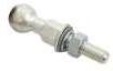


ATR17440-2
49 GROUNDING EQUIPMENT RITZ FERRAMENTAS A
Item Qty Unit Catalog Reference Description 01 01 pc RT600-2321 Ball-and-shell ground clamps T-handle for connection to the ball pin 02 01 pc RG3403T Grounding clamp, with T-handle for connection to the ground point 03 10 m CTC-35 Extra-flexible copper cable, 35 mm² cross-section, with transparent PVC insulation, being one 10 m length 04 01 pc ATR08969-2 Ball Stud pin for vehicle grounding point (M12 x 60 mm) 05 02 pc RC600-2626 35 mm² plain shrouded aluminum ferrule 06 02 pc ATR17923 Heat shrink 07 01 pc ATR08814-1 Ø 19 mm x 1 m ground rod hot-dip galvanized steel, hexagonal section and steel handle 08 01 pc ATR1628-1 Bag for storage and transport of ground rod 09 01 pc ATR16843-7 Bag for storage and transport of the grounding set Item 07 Item 01 Item 04 Item 02
Temporary Grounding Equipment for Vehicles (MV)
ATR17440-3
ATR17440-4
50 GROUNDING EQUIPMENT RITZ FERRAMENTAS A
| Maximum short-circuit current: 60 cycles - 5 kA
Item Qty. Unit. Catalog Reference Description 01 01 pc RG3363-1 Grounding clamp with T-handle 02 01 pc RG3403T Grounding clamp, with T-handle for connection to the ground point 03 10 m CTC-25 Extra-flexible copper cable, 25 mm² cross-section, with transparent PVC insulation, being one 10 m length 04 02 pc ATR13036-2 25 mm² plain shrouded aluminum ferrule 05 02 pc ATR17923 Heat shrink 06 01 pc ATR16843-7 Bag for storage and transport of the grounding set 07 01 pc ATR08814-1 Ø 19 mm x 1 m ground rod hot-dip galvanized steel, hexagonal section and steel handle 08 01 pc ATR1628-1 Bag for storage and transport of ground rod Item 07 Exclusive to the ATR17440-3 Item 01 Item 02
Item Qty. Unit. Catalog Reference Description 01 01 pc RG3363-1 Grounding clamp with T-handle 02 01 pc RG3403T Grounding clamp, with T-handle for connection to the ground point 03 10 m CTC-25 Extra-flexible copper cable, 25 mm² cross-section, with transparent PVC insulation, being one 10 m length 04 02 pc ATR13036-2 25 mm² plain shrouded aluminum ferrule 05 02 pc ATR17923 Heat shrink 06 01 pc ATR16843-7 Bag for storage and transport of the grounding set
Temporary Grounding Equipment for Underground Networks (MV)
| Maximum short-circuit current: 10 cycles - 10 kA

ATR20231-1-1
51 GROUNDING EQUIPMENT RITZ FERRAMENTAS A
Item Qty. Unit. Catalog Reference Description 01 01 pç 1001009 Disconnectable terminal TDC underground network DB 15kV 50-70mm² 02 01 pç 1001010 Connector for disconnectable terminal TDC underground network DB 15kV 50-70mm² 03 5.5 m CTPE-50 Extraflexible copper cable, nominal section 50mm², elastomeric compound insulation, 1 section of 5.5m 04 01 pç RC600-2631 Flat copper terminal for 50mm² cable 05 01 pç ATR17923 Heat-shrinkable for cables 06 01 pç ATR11627-2 Earthing clamp for earth point with T terminal 07 01 pç ATR14484-1 Bucket-type bag for packing the grounding set Item 06 Item 01
Temporary Grounding Equipment for Underground Networks (MV)

ATR20232-1-3
52 GROUNDING EQUIPMENT RITZ FERRAMENTAS A
| Maximum short-circuit current: 10 cycles - 10 kA
Item Qty. Unit. Catalog Reference Description 01 03 pç 1001009 Disconnectable terminal TDC underground network DB 15kV 50-70mm² 02 03 pç 1001010 Connector for disconnectable terminal TDC underground network DB 15kV 50-70mm² 03 8,5 m CTPE-50 Extraflexible copper cable, nominal section 50mm², elastomeric compound insulation, 3 sections of 1.5m and 1 section of 4m 04 01 pç ATR17574-1 Thermoplastic terminal block for ATR 05 04 pç ATR26446-4 Long tinned copper terminal for 50mm² cable 06 01 pç RC600-2631 Flat copper terminal for 50mm² cable 07 05 pç ATR17923 Heat-shrinkable for cables 08 01 pç ATR11627-2 Earthing clamp for earth point with T terminal 09 01 pç ATR14484-2 Bucket-type bag for packing the grounding set Item 08 Item 01 Item 04
HIGH VOLTAGE GROUNDING SETS
Temporary Grounding Set for Transmission Lines (HV)
Wood, concrete, and metal structure
| Maximum short-circuit current: 60 cycles - 25 kA


53 GROUNDING EQUIPMENT RITZ FERRAMENTAS
A
Item Qty. Unit. Catalog Reference Description 01 12 pc RC600-0965 Twisting grounding clamp, with eyescrew and serrated jaw 02 04 pc RG3626 Clamp resting support 03 01 pc ATR03318-1 Pole-mounted cluster bar, with wheel, for grounding intermediary point 04 27 m CTC-95 Extra-flexible copper cable, 95 mm² cross-section, with transparent PVC insulation, being three 4 m length, two 3 m length, and one 9 m length 05 12 pc RC600-2629 95 mm² plain shrouded aluminum ferrule 06 12 pc ATR17923-3 Heat shrink 07 01 pc VMR07205-1 Tool head for grounding clamp 08 01 pc ATR00137-1 Ø 17 mm x 1.5 m ground rod 09 01 pc ATR16819-2 Bag for storage and transport of ground rod 10 02 pc ATR09962-1 Bag for storage and transport of the grounding set Item 01 Item 03 Item 08
ATR17441-1
Temporary Grounding Set for Transmission Lines (HV) Metal structure
| Maximum short-circuit current: 60 cycles - 25 kA


ATR17442-1
54 GROUNDING EQUIPMENT RITZ FERRAMENTAS
A
Item Qty. Unit. Catalog Reference Description 01 03 pc RC600-1732 All angle Twisting grounding clamp with eyescrew 02 03 pc RC600-0085 Grounding clamp with T-handle for connection to the ground point 03 24 m CTC-95 Extra-flexible copper cable, 95 mm² cross-section, with transparent PVC insulation, being three 8 m length 04 03 pc RC600-2621 95 mm² threaded shrouded aluminum ferrule 05 03 pc RC600-2629 95 mm² plain shrouded aluminum ferrule 06 06 pc ATR17923-3 Heat shrink 07 03 pc ATR14484-2 Bag for storage and transport of the grounding set Item 01 Item 02
Temporary Grounding Set for Substation (HV)
| Maximum short-circuit current: 60 cycles - 25 kA

ATR17454-1
55 GROUNDING EQUIPMENT RITZ FERRAMENTAS A
Item Qty. Unit. Catalog Reference Description 01 03 pc RC600-1732 All angle grounding clamp with bus eyescrew 02 03 pc RC600-2231 T-handle grounding clamp for connection to ground point (cable or angle bar) 03 30 m CTC-95 Extra-flexible copper cable, 95 mm² cross-section, with transparent PVC insulation, being three 10 m length 04 06 pc RC600-2621 95 mm² threaded shrouded aluminum ferrule 05 06 pc ATR17923-3 Heat shrink 06 01 pc VMR02579-1 Clamp tool head 07 01 pc VMR00884-1 Switching tool head 08 03 pc ATR14484-1 Bag for storage and transport of the grounding set Item 01 Item 02
Temporary Grounding Set for Substation (HV)
| Maximum short-circuit current: 60 cycles - 25 kA

ATR17454-2
56 GROUNDING EQUIPMENT RITZ FERRAMENTAS
A
Item Qty. Unit. Catalog Reference Description 01 03 pc RG3368 Twisting grounding clamp, with eyescrew and smooth jaw 02 03 pc RG3363-1 Grounding clamp with T-handle for connection to the ground point 03 30 m CTC-95 Extra-flexible copper cable, 95 mm² cross-section, with transparent PVC insulation, being three 10 m length 04 06 pc RC600-2629 95 mm² plain shrouded aluminum ferrule 05 06 pc ATR17923-3 Heat shrink 06 01 pc VMR02579-1 Clamp tool head 07 01 pc VMR00884-1 Switching tool head 08 03 pc ATR14484-1 Bag for storage and transport of the grounding set Item 01 Item 02
Temporary Grounding Set for Substation (HV)
| Maximum short-circuit current: 60 cycles - 25 kA

ATR00395-8
57 GROUNDING EQUIPMENT RITZ FERRAMENTAS A
Item Qty. Unit. Catalog Reference Description 01 03 pc RG4228-10SJ All angle Twisting grounding clamp with eyescrew 02 03 pc RG3363-1 Grounding clamp with T-handle for connection to the ground point 03 24 m CTC-95 Extra-flexible copper cable, 95 mm² cross-section, with transparent PVC insulation, being three 8 m length 04 06 pc RC600-2629 95 mm² plain shrouded aluminum ferrule 05 06 pc ATR17923-3 Heat shrink 06 01 pc VMR02579-1 Clamp tool head 07 01 pc VMR00884-1 Switching tool head 08 03 pc ATR14484-2 Bag for storage and transport of the grounding set Item 01 Item 02

LIFTING AND INSTALLATION TOOL FOR SUBSTATION GROUNDING
This tool kit allows the lifting and installation of temporary grounding sets on buses in extra-high voltage substation, directly from the ground, at a height of up to 8 m.
Tip sections (ATR01875-1 and VMR/S-SP) must be coupled to separate hot sticks with lengths compatible with the substation bus height.
Section ATR01875-1 must be installed on the bus through the support hook
The VMR/S-SP section will lift the clamp and ground cable

58 GROUNDING EQUIPMENT RITZ FERRAMENTAS
A
Item Qty. Unit. Catalog Reference Description Working Length (m) Approx. Weight kg lb 01 01 pc ATR01875-1 Hot stick and tip section with support hook and snatch block 1.25 3.50 7.72 02 01 pc VMR/S-SP Hot stick, tip section with universal head and hinged clamp 1.25 1.50 2.76 03 20 m RM1895-2 Ø 3/8” Polypropylene Rope - 0.05 0.11 VMR/S-SP ATR01875-1 ACESSORIES Item Qty. Unit. Catalog Reference Description Working Length (m) Approx. Weight kg lb 04 * pc VMR-I Hot stick middle section 1.25 1.20 2.65 05 01 pc VMR-P Hot stick handle section 1.45 1.10 2.43 06 01 pc ** Bag for hot stick storage - - -
Quantity defined according to bus height
Bag defined according to the amount of sections of the Maneuver Stick
ATR23989-1
*
**
STATIC GROUNDING SET
This static grounding set is designed to reliably remove static loads on deenergized systems such as: connection terminals and conductors on transformers or generators.
To operate this tool, first connect the grounding clamp to a safe ground point.
Then, using the copper hook, install the stick at the point where the static charge must be discharged from the system.
When maintenance is complete, use the same sequential procedure adopted in the installation, but in the opposite order That is: first remove the ground stick from the work point and then disconnect the grounding clamp.
| RT600-0891
Ø 32 mm x 1,07 m RITZGLAS® stick composed of: 1 twisting duckbill clamp with T-handle (RG3363-4SJ) and 2.10 m of extra-flexible copper cable 25 mm² cross-section, with transparent PVC insulation
Approx. Weight: 2.60 kg (5.73 lb)

59 GROUNDING EQUIPMENT RITZ FERRAMENTAS
A

GROUNDING CLAMP
Ball Studs and Ball-and-Socket Clamps for Temporary Grounding
The ball stud and ball-and-socket clamp are designed to solve countless temporary grounding situations where space or contact surfaces are limited. In switchgears, especially with rectangular buses, where conventional ground clamps have dimensions that preven their use, the ball-and socket clamp stands out for its versatile design and easy operation.
This clamp is very popular in electrical installations such as:
- switchgears;
- indoor and outdoor substations;
- overhead cranes;
- hot line vehicles;
- painted transmission line structures where optimum electrical contact with conventional clamps is not obtained.
Ball studs are designed for permanent installations in buses, bus junctions, terminals or other parts of the electrical installation, establishing the points necessary for their proper temporary grounding. Therefore, purchasing them in sufficient quantities for such use is recommended
To best suit the user needs, they are arranged with seven variations in connecting ball length and position.
Bronze alloy body and tin-plated 1020 steel thread and 3.5 daN.m installation torque
BALL STUDS (STRAIGHT)
BALL STUD (L-TYPE)
60 GROUNDING EQUIPMENT RITZ FERRAMENTAS
A
Catalog Reference A B C Approx. Weight kg lb ATR08969-1 98 58 40 0,22 0,48 ATR08969-2 118 58 60 0,24 0,53 ATR08969-3 138 58 80 0,25 0,55 ATR08969-4 108 58 50 0,23 0,51 ATR08969-5 166 114 52 0,28 0,62 ATR08969-6 158 58 100 0,30 0,66 ATR08969-7 82 58 100 0,28 0,62
Catalog Reference A B C Approx. Weight kg lb ATR13147-1 91 50 65 0.26 0.57 M12 Ø 26 A B C A B C Ø 26 M12
BALL-AND-SHELL GROUND CLAMPS


61 GROUNDING EQUIPMENT RITZ FERRAMENTAS
A
Electrical and Mechanical Characteristics Catalog Reference RC600-2300 RC600-2101 ATR08968-1 RT600-2321 RT600-2320 Description Bronze alloy main body; Eyescrew; Cable connection through plain ferrule Bronze alloy main body; Eyescrew; Cable connection through threaded ferrule Bronze alloy main body; Eyescrew; Cable connection through tin-plated copper ferrule Bronze alloy main body; T-handle; Cable connection through plain ferrule Bronze alloy main body; T-handle; Cable connection through threaded ferrule Rated Current (A) 400 400 400 400 400 Short circuit current (lcc) 30 cycles (kA) 30 30 30 30 30 60 cycles (kA) 23 23 23 23 23 Connection Ø 26 Ø 26 Ø 26 Ø 26 Ø 26 Cable Ferrule (mm²) Maximum 95 95 95 95 95 Minimum 25 25 25 25 25 Installation Torque (daN.m) 3.0 3.0 3.0 3.0 3.0 ASTM Designation Type I Class A Grade 5 Type I Class A Grade 5 Type I Class A Grade 5 Type III Class A Grade 5 Type III Class A Grade 5 Approx.Weight. (kg/lb) 0.76 / 1.68 0.45 / 0.99 0.40 / 0.88 0.82 / 1.81 0.45 / 0.99
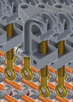


Multi-Connection Grounding Clamp
The RC600-2316 grounding clamp can be installed on circular conductors, rectangular bars and ball studs. Its two threaded housings can be used to install ball studs in its body for the simultaneous lifting of two additional clamps for a three-phase grounding system.
62 GROUNDING EQUIPMENT RITZ FERRAMENTAS A
Electrical and Mechanical Characteristics Catalog Reference RC600-2316 Description Aluminum main body; Eyescrew; Cable connection through plain threaded ferrule Rated Current (A) 400 Short circuit current (lcc) 30 cycles (kA) 30 60 cycles (kA) 23 Connection Maximum 636 MCM CAA Ø 25 mm Minimum 8 Cu Ø 2.6 mm Cable Ferrule (mm²) Maximum 95 Minimum 16 Installation Torque (daN.m) 3.0 ASTM Designation Type I Class A Grade 5 Approx. Weight (kg / lb) 0.68 / 1.50
TEMPORARY GROUND CLAMPS

Electrical and Mechanical
Description
Aluminium body; Smooth jaw; Conductor-mounted to conductor; connection to cluster bar (ATR04694-1) galvanized steel.
Cable connection through tin-plated copper ferrule (not included in clamp)


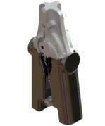
Catalog Reference
Aluminium body; Smooth jaw; Spring-loaded mounting connection blade springloaded; cluster bar (ATR14442-1) self-locking system;
Cable connection through tin-plated copper ferrule (not included in clamp)
Aluminium body; Spring-loaded tap cable installation; Red plastic handle
Aluminium body; Spring-loaded tap cable installation; Black plastic handle
63 GROUNDING EQUIPMENT RITZ FERRAMENTAS
A
Characteristics
ATR03653-1 ATR13628-1 ATR13047-1 ATR13047-2
Rated Current (A) - - -Shortcircuit Current (lcc) 30 cycles (kA) 10 15 10 10 60 cycles (kA) 7 8 7 7 Connection Maximum 336,4 MCM CAA Ø 19 mm Ø 30 mm Ø 12,5 mm Ø 12,5 mm Minimum 6 AWG Cu 4 AWG CA Ø 4 mm Ø 5 mm Ø 6,5 mm Ø 6,5 mm Cable Ferrule (mm²) Maximum 35 50 35 35 Minimum 16 16 16 16 Installation Torque (daN.m) - - -ASTM Designation -Type III Class B Grade 5 Type III Class B Grade 5 Approx. Weight (kg / lb) 0.35 / 0,77 0.45 / 0.99 0.35 / 0.77 0.35 / 0.77
TEMPORARY GROUND CLAMPS


Catalog Reference
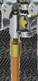


Description
Bronze body; Mounted to insulated pole Ø 1/2” x 640 mm, with rubber handle; Cable connection through tin-plated copper ferrule (not included in clamp)
Bronze body; Mounted to insulated pole Ø 1/2” x 640 mm, with rubber handle; Cable connection through plain ferrule
Aluminum body; Smooth jaw; Mounted to Ø 25 mm x 300 mm insulating tube, with rubber handle; springloaded mounting to conductor;
Cable connection through tin-plated copper ferrule (not included in clamp)
Clamp mainly designed for switchgear grounding with vertical rectangular buses. Aluminum body; Smooth jaw; Mounted to insulated pipe Ø 25 mm x 600 mm, with rubber handle;
Cable connection through plain ferrule
Clamp mainly designed for switchgear grounding with vertical rectangular buses.
Aluminum body; Serrated jaw; Mounted to insulated pipe Ø 25 mm x 600 mm, with rubber handle;
Cable connection through plain ferrule
64 GROUNDING EQUIPMENT RITZ FERRAMENTAS
A
Electrical and Mechanical Characteristics
ATR08947-1 ATR09033-1 ATR17348-1 ATR19433-1 ATR19357-1
Rated Current (A) 200 200 - 400 400 Shortcircuit Current (lcc) 30 cycles (kA) 8 8 10 30 30 60 cycles (kA) 5 5 7 23 23 Connection Maximum Ø 30 mm Ø 19 mm 336.4 MCM CAA Ø 19 mm 20 mm (rectangular buses) 38 mm (rectangular buses) Minimum Ø 4 mm Ø 4 mm 6 AWG Cu 4 AWG CA Ø 4 mm 3 mm (rectangular buses) 3,2 mm (rectangular buses) Cable Ferrule (mm²) Maximum 25 25 35 95 95 Minimum 16 16 16 16 16 Installation Torque (daN.m) 2.0 2.0 - 3.0 3.0 ASTM Designation - -Type II Class A Grade 5 Type II Class B Grade 5 Approx. Weight (kg / lb) 0.75 / 1.65 0.65 / 1.43 0.36 / 0.79 0.72 / 1.59 0.85 / 1.87
TEMPORARY GROUND CLAMPS


65 GROUNDING EQUIPMENT RITZ FERRAMENTAS A
Electrical and Mechanical Characteristics Catalog Reference ATR17461-1 ATR17460-1 ATR17462-1 ATR17459-1 Description Aluminum body; Smooth jaw; Mounted to hot stick tip section Ø 25 mm x 1.25 m, with coupling system; Cable connection through plain ferrule Aluminum body; Smooth jaw; Mounted to telescopic hot stick, Ø 33 mm base, retracted length 1 m and extended length 1.80 m; Cable connection through plain ferrule Aluminium body; Smooth jaw; Fixed to telescopic hot stick - Ø 33 mm base, retracted length 1.43 m and extended length 2.58 m; Cable connection through plain ferrule Aluminium body; Smooth jaw; Mounted to insulating tube Ø 25 mm x 1,25 m; Cable connection through plain ferrule Rated Current (A) 300 300 300 300 Shortcircuit Current (lcc) 30 cycles (kA) 20 20 20 20 60 cycles (kA) 15 15 15 15 Connection Maximum 477 MCM CAA Ø 22.5 mm 477 MCM CAA Ø 22.5 mm 477 MCM CAA Ø 22.5 mm 477 MCM CAA Ø 22.5 mm Minimum 6 AWG Cu 4 AWG CA Ø 4 mm 6 AWG Cu 4 AWG CA Ø 4 mm 6 AWG Cu 4 AWG CA Ø 4 mm 6 AWG Cu 4 AWG CA Ø 4 mm Cable Ferrule (mm²) Maximum 70 70 70 70 Minimum 16 16 16 16 Installation Torque (daN.m) 3.0 3.0 3.0 3,0 ASTM Designation Type II Class A Grade 3 Type II Class A Grade 3 Type II Class A Grade 3 Type II Class A Grade 3 Approx. Weight (kg / lb) 1.10 / 2.43 1.40 / 3.09 1.40 / 3.09 1.10 / 2.43
TEMPORARY GROUND CLAMPS


connection
02
66 GROUNDING EQUIPMENT RITZ FERRAMENTAS
A
Electrical and Mechanical Characteristics
Reference RG3403 RG3404-1 ATR11627-1 Description Aluminum body;
jaw;
ferrule
Catalog
Smooth
Eyescrew; Cable connection through plain
Aluminium body; Smooth jaw; Eyescrew; Cable connection
plain ferrule Rated Current (A) 300 300 400 ShortCircuit Current (lcc) 30 cycles (kA) 20 20 30 60 cycles (kA) 15 15 23 Connection Maximum 477 MCM CAA Ø 22.5 mm Ø 22.5 mm Buses vertical 40 mm horizontal 44 mm circular 35 mm Minimum 6 AWG Cu 4 AWG CA Ø 4 mm Ø 4 mm Buses vertical 6 mm circular 6 mm Cable Ferrule (mm²) Maximum 70 70 95 Minimum 16 16 16 Installation Torque (daN.m) 3.0 3.0 3,0 ASTM Designation Type I Class A Grade 3 Type I Class A Grade 3 Type I Class A Grade 5 Approx. Weight (kg / lb) 0.48 / 1.06 0.48 / 1.06 0.65 / 1.43
Allows the
of
threaded terminals in the same clamp body Aluminium body; Smooth jaw; Eyescrew; Cable connection through threaded ferrule
through
TEMPORARY GROUND CLAMPS


*It allows the use of two 95 mm² cables simultaneously
67 GROUNDING EQUIPMENT RITZ FERRAMENTAS A
Electrical and Mechanical Characteristics Catalog Reference RG3368 RG3367-2 RG3369 RC600-0337* ATR03308-2* Description Aluminium body; Smooth jaw; Eyescrew; Cable connection through plain ferrule Aluminium body; Removable and smooth jaw; Eyescrew; Cable connection through plain ferrule Adjustable aluminum body and shoe; Smooth jaw; Eyescrew; Cable connection through plain ferrule Adjustable aluminum body and shoe; Smooth jaw; Eyescrew; Cable connection through plain ferrule Adjustable aluminum body and shoe; Smooth jaw; Eyescrew; Cable connection through plain ferrule Rated Current (A) 400 400 400 400 400 Shortcircuit Current (lcc) 30 cycles (kA) 30 30 30 30 30 60 cycles (kA) 23 23 23 23 23 Connection Maximum Ø 50 mm or 12 x 100 mm rectangular buses Ø 63,5 mm Ø 100 mm Ø 160 mm Ø 235 mm Minimum Ø 5 mm Ø 6 mm Ø 10 mm Ø 90 mm Ø 115 mm Cable Ferrule (mm²) Maximum 95 95 95 95 95 Minimum 16 16 16 16 16 Installation Torque (daN.m) 3.0 3.0 3.0 3.0 3.0 ASTM Designation Type I Class A Grade 5 Type I Class A Grade 5 Type I Class A Grade 5 Type I Class A Grade 5 Type I Class A Grade 5 Approx. Weight (kg / lb) 1.00 / 2,20 1.20 / 2.65 2.20 / 4.85 3.20 / 7.05 3.20 / 7.05
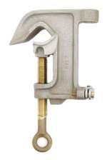


Catalog Reference
Aluminium body; Smooth jaw; Eyescrew; Cable connection through unshrouded threaded ferrule
Aluminium body; Smooth jaw; Connectors and eyescrew; Cable connection through plain ferrule
Aluminium body; Smooth jaw; Steel clamp for securing the protected cable with a perimeter from 51 to 70 mm; Connectors and eyescrew; Cable connection through threaded ferrule
Aluminium body; Serrated jaw; Eyescrew; Cable connection through plain ferrule
Aluminium body; Serrated jaw; Eyescrew; Cable connection through threaded ferrule
68 GROUNDING EQUIPMENT RITZ FERRAMENTAS
A
TEMPORARY GROUND CLAMPS Electrical and Mechanical Characteristics
RC600-1743 RG3622-1 RG3622-2
RC600-0434 RC600-0065 Description
Rated Current (A) 400 400 400 400 400 Shortcircuit Current (lcc) 30 cycles (kA) 30 30 30 30 30 60 cycles (kA) 23 23 23 23 23 Connection Maximum 1000 MCM Cu 1590 MCM CAA Ø 38 mm 566 MCM Cu 900 MCM CAA Ø 29 mm 566 MCM Cu 900 MCM CAA Ø 29 mm 950 MCM Cu 1510 MCM CAA Ø 38 mm 954 MCM CAA Ø 30 mm Minimum 6 Cu Ø 4 mm 6 Cu Ø 4 mm 6 Cu Ø 4 mm 6 Cu Ø 4 mm 6 Cu Ø 4 mm Cable Ferrule (mm²) Maximum 95 95 95 95 95 Minimum 16 16 16 16 16 Installation Torque (daN.m) 3.0 3.0 3,0 3.0 3.0 ASTM Designation Type I Class A Grade 5 Type I Class A Grade 5 Tipo I Classe A Grau 5 Type I Class B Grade 5 Type I Class B Grade 5 Approx. Weight (kg / lb) 0.72 / 1.59 0.72 / 1.59 0,76 / 1,68 0.92 / 2.03 0.52 / 1.15
TEMPORARY GROUND CLAMPS


69 GROUNDING EQUIPMENT RITZ FERRAMENTAS A
Electrical and Mechanical Characteristics
Reference RG4229-1SJ ATR13159-1 RHG4229-6SJ Description
body; Serrated Jaw; Eyescrew; Cable connection through plain ferrule;
operation at continuous angles up to 75°
Catalog
Aluminium
Allows
Aluminium body; Serrated Jaw; Eyescrew; Cable connection through plain ferrule;
Locking of preset and fixed operating angles by wing nut
Mounted to RITZGLAS® tube
32 mm x 1.83
plain
operation at continuous angles up to 75° Rated Current (A) 400 400 400 Shortcircuit Current (lcc) 30 cycles (kA) 30 30 30 60 cycles (kA) 23 23 23 Connection Maximum 954 MCM CAA Ø 30 mm 954 MCM CAA Ø 30 mm 954 MCM CAA Ø 30 mm Minimum 2 Cu Ø 6.5 mm 2 Cu Ø 6,5 mm 2 Cu Ø 6,5 mm Cable Ferrule (mm²) Maximum 95 95 95 Minimum 16 16 16 Installation Torque (daN.m) 3.0 3.0 3.0 ASTM Designation Type I Class B Grade 5 Type I Class B Grade 5 Type II Class B Grade 5 Approx. Weight (kg / lb) 1.15 / 2.54 1.90 / 4.19 2.00 / 4.41
Aluminium body; Serrated Jaw; Cable connection
Ø
m; Cable connection through
ferrule; Allows
TEMPORARY


Aluminium body; Serrated Jaw; Eyescrew; Cable connection through threaded ferrule;
Allows operation at continuous angles up to 75°
Aluminum body; Serrated jaw; Eyescrew; Cable connection through plain ferrule.
Allow operation at continuous angles up to 75 °
Aluminum body; Serrated jaw; Eyescrew; Cable connection through plain ferrule.
Locking of preset and fixed operating angles by wing nut
Aluminum body; Serrated jaw; Fixed to Ø 32 mm x 1.83 m RITZGLAS® tube; Cable connection through plain ferrule.
Allow operation at continuous angles up to 75 °
70 GROUNDING EQUIPMENT RITZ FERRAMENTAS
A
GROUND CLAMPS Electrical and Mechanical Characteristics
RC600-1732 RG4228-10SJ ATR10777-1 RHG4228-16SJ
Catalog Reference
Description
Rated Current (A) 400 400 400 400 Shortcircuit Current (lcc) 30 cycles (kA) 30 30 30 30 60 cycles (kA) 23 23 23 23 Connection Maximum Ø 73 mm Ø 73 mm Ø 73 mm Ø 73 mm Minimum 2 Cu Ø 6,5 mm 2 Cu Ø 6.5 mm 2 Cu Ø 6.5 mm 2 Cu Ø 6.5 mm Cable Ferrule (mm²) Maximum 95 95 95 95 Minimum 16 16 16 16 Installation Torque (daN.m) 3.0 3,0 3,0 3,0 ASTM Designation Type I Class B Grade 5 Type I Class B Grade 5 Type I Class B Grade 5 Type II Class B Grade 5 Approx. Weight (kg / lb) 1.50 / 3.31 1.85 / 4.08 2.60 / 5.73 3.30 / 7.28
TEMPORARY GROUND CLAMPS


71 GROUNDING EQUIPMENT RITZ FERRAMENTAS A
Electrical and Mechanical Characteristics Catalog Reference RC600-0965 RC600-2282 RC600-0386 Description Aluminium body; Serrated Jaw; Eyescrew; Cable connection through plain ferrule Aluminium body; Serrated Jaw; Eyescrew; Cable connection through plain ferrule Aluminium body; Serrated Jaw; Fixed to Ø 32 mm x 1.83 m RITZGLAS® tube; Cable connection through plain ferrule Rated Current (A) 400 400 400 Shortcircuit Current (lcc) 30 cycles (kA) 30 30 30 60 cycles (kA) 23 23 23 Connection Maximum 954 MCM CAA Ø 30 mm Ø 51 mm Ø 51 mm Minimum 6 Cu Ø 4 mm 6 Cu Ø 4 mm 6 Cu Ø 4 mm Cable Ferrule (mm²) Maximum 95 95 95 Minimum 16 16 16 Installation Torque (daN.m) 3.0 3.0 3.0 ASTM Designation Type I Class B Grade 5 Type I Class B Grade 5 Type II Class B Grade 5 Approx. Weight (kg / lb) 0.73 / 1.61 0.90 / 1.98 2.15 / 4.74
TEMPORARY GROUND CLAMPS


Catalog Reference RG3403T RG3404-2 RG3363-4SJ RG3363-1 RC600-0085
Description
Aluminum body; Smooth jaw; T-handle; Cable connection through plain ferrule
Allows the connection of 02 threaded terminals in the same clamp body
Aluminium body; Smooth jaw; T-handle; Cable connection through threaded ferrule
Aluminium body; Serrated Jaw; T-handle; Cable connection through plain ferrule
Aluminium body; Serrated Jaw; T-handle; Cable connection through plain ferrule
Aluminium body; Bronze pad for better contact of jaw with angle bar surface; Aluminum flange (removable) for mounting to the angle bar; T-handle; Cable connection through plain ferrule
72 GROUNDING EQUIPMENT RITZ FERRAMENTAS
A
Electrical and Mechanical Characteristics
Rated Current (A) 300 300 400 400 400 Shortcircuit Current (lcc) 30 cycles (kA) 20 20 30 30 30 60 cycles (kA) 15 15 23 23 23 Connection Maximum 477 MCM CAA Ø 22.5 mm Ø 22.5 mm 38 mm (rectangular buse) Ø 32 mm 51 a 102 mm (rectangular buse) Minimum 6 AWG Cu 4 AWG CA Ø 4 mm Ø 4 mm 3,2 mm (rectangular buse) Ø 5 mmCable Ferrule (mm²) Maximum 70 70 95 95 95 Minimum 16 16 16 16 16 Installation Torque (daN.m) 3.0 3.0 3.0 3.0 3.0 ASTM Designation Type I Class A Grade 3 Type III Class A Grade 3 Type III Class B Grade 5 Type III Class B Grade 5 Type III Class B Grade 5 Approx. Weight (kg / lb) 0.48 / 1.06 0.48 / 1.06 0.84 / 1.85 0.79 / 1.75 1.70 / 3.75
TEMPORARY GROUND CLAMPS


73 GROUNDING EQUIPMENT RITZ FERRAMENTAS A
Electrical and Mechanical Characteristics Catalog Reference ATR11627-2 RC600-1617 RC600-2231 ATR16449-3 RG3622-1T Description Aluminium body; Smooth jaw; T-handle; Cable connection through plain ferrule Bronze body; Mobile serrated jaw; T-handle; Cable connection through plain ferrule Bronze body; Serrated Jaw; T-handle; Cable connection through Unshrouded threaded ferrule Bronze body; Serrated Jaw; T-handle; Cable connection through Unshrouded threaded ferrule Aluminium body; Smooth jaw; T-handle; Cable connection through plain ferrule Rated Current (A) 400 400 400 400 400 Shortcircuit Current (lcc) 30 cycles (kA) 30 30 30 30 30 60 cycles (kA) 23 23 23 23 23 Connection Maximum Buses: vertical 40 mm horizontal 44 mm circular 35 mm 25,4 mm (rectangular buses) 38 mm (rectangular buses) 38 mm (rectangular buses) 566 MCM Cu 900 MCM CAA Ø 29 mm Minimum Buses: vertical 6 mm circular 6 mm 3 mm (rectangular buses) 3 mm (rectangular buses) 3 mm (rectangular buses) 6 Cu Ø 4.0 mm Cable Ferrule (mm²) Maximum 95 95 95 95 95 Minimum 16 16 16 16 16 Installation Torque (daN.m) 3.0 3.0 3.0 3.0 3.0 ASTM Designation Type III Class A Grade 5 Type III Class B Grade 5 Type III Class B Grade 5 Type III Class B Grade 5 Type III Class A Grade 5 Approx. Weight (kg / lb) 0.70 / 1.54 1.20 / 2.65 0.90 / 1.98 0.90 / 1.98 0.76 / 1.68 Threaded
Straight Ferrule
Ferrule
RC600-0861

Cutout Grounding Clamps
| Maximum short-circuit current: 30 cycles - 20 kA
Specially designed clamp for temporary grounding of the cutout in medium voltage networks by installing it on the bottom base of the cutout after removal of the cartridge
RC600-0862


Cables can be attached directly to this clamp (either to the conventional grounding clamp or to the “L” or “T” brackets). Another great use for this clamp is that it prevents the cutout from being accidentally switched while it is in the mains
The body and studs “L” and “T” are made of aluminum alloy with a bronze alloy eyescrew.
ATR01726-3


Grounding Clamp for Hookstick Switch
| Maximum short-circuit current: 30 cycles - 20 kA
| ATR01726-3
This clamp has been specially designed for temporary grounding of hookstick switches in medium voltage systems. It has body and jaws in cast aluminum alloy and eye screw of maneuver in cast bronze alloy, in which it makes possible the installation through means of stick or maneuvering rod. It has "T" support in cast aluminum alloy, where another grounding clamps can be connected, for connect to the ground point.
Approx. Weight: 1.20 kg (2.65 lb)
74 GROUNDING EQUIPMENT RITZ FERRAMENTAS
A
Catalog Reference Description Approx. Weight kg lb RC600-0861 Cutout grounding clamps with T-stud 0.73 1.61 RC600-0862 Cutout grounding clamps with L-stud 0.67 1.48
COPPER CABLES FOR GROUNDING
Extra flexible electrolytic cable with 750 V and translucent PVC insulated protection, allowing inspections of the perfect condition of the copper filaments. It is suitable for use on temporary and terminal grounding.
For easy size identification and classification, the application and year of manufacture are engraved on the entire length of the cable.


ALUMINUM CABLE FOR TEMPORARY GROUNDING


75 GROUNDING EQUIPMENT RITZ FERRAMENTAS A Cr oss Sec tion (mm²) A W G Size (mm²) 60 c y cles (1 Seg .) R a ted C urr ent ( A ) Maximum Elec trical Resistanc e 20º C (ohms / k m) W ir e F orma tion Ø ØW ir e Maximum (mm) Ø Ex ternal (mm) Minimum Insula tion T hick ness (mm)
GROUNDING
Catalog Reference Icc Capacity (symmetric kA) Approx. Weight kg/m lb/m CTC-25 25 - 5.0 150 0.795 19 x 42 0.26 11.52 1.8 0.300 0.661 CTC-35 35 2 (33.63) 8.0 200 0.565 37 x 30 0.31 12.90 2.0 0.400 0.882 CTC-50 50 1/0 (53.48) 10.0 250 0.386 19 x 52 0.31 14.53 2.0 0.545 1.202 CTC-70 70 2/0 (67.42) 15.0 300 0.272 61 x 23 0.31 17.00 2.2 0.765 1.687 CTC-95 95 4/0 (107.20) 25.0 400 0.210 51 x 31 0.31 19.03 2.2 1.000 2.205
COPPER CABLES FOR
EQUIPMENT
Cr oss Sec tion (mm²) A W G Size (mm²) 60 c y cles (1 Seg .) R a ted C urr ent ( A ) Maximum Elec trical Resistanc e 20º C (ohms / k m) W ir e F orma tion Ø ØW ir e Maximum (mm) Ø Ex ternal (mm) Minimum Insula tion T hick ness (mm)
Aluminum cable Copper cable Aluminum cable Copper cable
Catalog Reference Icc Capacity (symmetric kA) Approx. Weight kg/m lb/m CTA-35 35 2 (33.63) 5.0 150 0.886 7x 44 0.46 11.7 2.0 0.186 0.410
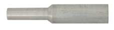
GROUND CABLE FERRULE
Fixed at the ends of the grounding cables (internal diameters adjusted to the nominal section of the cable) through the pressing process, establishing a solid electrical and mechanical connection with the grounding clamps.
Allows two pressing options: Shrouded , which covers the PVC ferrule protection and the cable, and unshrouded ferrule, which presses only the conductor


Shrouded plain aluminium ferrule

Shrouded threaded aluminium ferrule
76 GROUNDING EQUIPMENT RITZ FERRAMENTAS A
Catalog Reference For Cross-Section Copper Cables (mm²) Description Approx. Weight kg lb ATR17179-2 25 Unshrouded plain 0.07 0.15 RC600-2610 35 Unshrouded plain 0.07 0.15 RC600-2611 50 Unshrouded plain 0.07 0.15 RC600-2612 70 Unshrouded plain 0.08 0.18 RC600-2613 95 Unshrouded plain 0.08 0.18 ATR17185-2 25 Unshrouded threaded 0.06 0.06 RC600-2602 35 Unshrouded threaded 0.06 0.06 RC600-2603 50 Unshrouded threaded 0.06 0.06 RC600-2604 70 Unshrouded threaded 0.07 0.15 RC600-2605 95 Unshrouded threaded 0.08 0.18 ATR13036-2 25 Shrouded plain 0.06 0.13 RC600-2626 35 Shrouded plain 0.06 0.13 RC600-2627 50 Shrouded plain 0.06 0.13 RC600-2628 70 Shrouded plain 0.07 0.15 RC600-2629 95 Shrouded plain 0.07 0.15 ATR17184-2 25 Shrouded threaded 0.07 0.15 RC600-2618 35 Shrouded threaded 0.07 0.15 RC600-2619 50 Shrouded threaded 0.07 0.15 RC600-2620 70 Shrouded threaded 0.08 0.18 RC600-2621 95 Shrouded threaded 0.08 0.18 Section B Shrouded Plain Ferrule Cable Section A Section B Shrouded Threaded Ferrule Cable Section A Unshrouded Threaded Ferrule Cable Unshrouded Plain Ferrule Cable
plain aluminium ferrule
ALUMINUM FERRULE
Unshrouded
Unshrouded threaded aluminium ferrule
COPPER FERRULE
These ferrules are designed to be connected to clamps through screws.


77 GROUNDING EQUIPMENT RITZ FERRAMENTAS A
Catalog Reference For Cross-Section Copper Cables (mm²) Description Approx. Weight kg lb ATR17179-8 25 Unshrouded plain 0.10 0.22 RC600-2614 35 Unshrouded plain 0.10 0.22 RC600-2615 50 Unshrouded plain 0.20 0.44 RC600-2616 70 Unshrouded plain 0.20 0.44 RC600-2617 95 Unshrouded plain 0.23 0.51 ATR17185-8 25 Unshrouded threaded 0.12 0.26 RC600-2606 35 Unshrouded threaded 0.12 0.26 RC600-2607 50 Unshrouded threaded 0.13 0.29 RC600-2608 70 Unshrouded threaded 0.15 0.33 RC600-2609 95 Unshrouded threaded 0.16 0.35 ATR13036-8 25 Shrouded plain 0.18 0.40 RC600-2630 35 Shrouded plain 0.18 0.40 RC600-2631 50 Shrouded plain 0.20 0.44 RC600-2632 70 Shrouded plain 0.23 0.51 RC600-2633 95 Shrouded plain 0.23 0.51 ATR17184-8 25 Shrouded threaded 0.20 0.44 RC600-2622 35 Shrouded threaded 0.20 0.44 RC600-2623 50 Shrouded threaded 0.23 0.51 RC600-2624 70 Shrouded threaded 0.23 0.51 RC600-2625 95 Shrouded threaded 0.23 0.51
Catalog Reference For Cross-Section Copper Cables (mm²) Description Approx. Weight kg lb ATR26446-2 25 Tin-plated copper 0.02 0.04 ATR26446-3 35 Tin-plated copper 0.02 0.04 ATR26446-4 50 Tin-plated copper 0.03 0.07 ATR26446-5 70 Tin-plated copper 0.04 0.09 ATR26446-6 95 Tin-plated copper 0.06 0.13
TIN-PLATED COPPER FERRULE
Unshrouded plain copper ferrule
Unshrouded threaded copper ferrule
Shrouded plain copper ferrule
Shrouded threaded copper ferrule
| ATR04694-1

GROUNDING CLUSTER
Grounding cluster bars are designed to simultaneously raise grounding clamps to conductors in a safe sequence of operations
They are commonly used in conventional medium voltage overhead lines interventions.
| ATR04116-1

Made of aluminum and galvanized steel rod and universal bronze fitting, this cluster bar is suitable for installation and removal of spring-loaded grounding clamps (ATR03653-1).
Approx. Weight : 0.53 kg (1.17 lb)
| ATR14442-1

Made of aluminum and galvanized steel rod, this model is suitable for lifting, installing, and removing ATR13628-1 spring-loaded clamps.
Approx. Weight: 0.68 kg (1.50 lb)
Made of aluminum with bronze connectors, it is suitable for medium size clamps
Approx. Weight: 1.0 kg (2.20 lb)
| ATR18867-1

Made of aluminum with bronze connectors, it is suitable for small size clamps
Approx. Weight: 0.40 kg (0.88 lb)
78 GROUNDING EQUIPMENT RITZ FERRAMENTAS
A
SADDLE-TYPE CLUSTER
The five saddle-type cluster bars models allow the formation of an intermediate ground point in the work structure.
| ATR03318-1

Made of aluminum, it has a belt chain and tightening wheel for perfect electrical contact with the pole
Approx. weight 3.17 kg (6.99 lb)
| ATR14477-1

Made with pole-mounting chain device, nylon rod and wing nut for cable connection.
Approx. weight: 0.43 kg (0.95 lb)
| RC600-0152

Made with aluminum plate and copper shaft. Can be connected by plain terminals to grounding cables from 16 to 95 mm².
Approx. weight 4.30 kg (9.48 lb)
79 GROUNDING EQUIPMENT RITZ FERRAMENTAS
A


AUXILIARY EQUIPMENT
Clamp Resting Supports
Designed for simultaneous lifting of the clamps to be installed
The resting supports are suitable for any type of clamps, being the model
RC600-0080 specific for attachment of clamps with threaded ferrules.
CLAMP RESTING SUPPORTS

Metallic Reel
Metallic reel, with bronze clamp mounting, to connect the cable to the grounding rod and can store the cable during transport.
80 GROUNDING EQUIPMENT RITZ FERRAMENTAS
A
Catalog Reference Material Approx. Weight kg lb RG3625 Aluminium 0.13 0.29 RG3626 Aluminium 0.06 0.13 RC600-0080 Bronze 0.15 0.33
Electrical and Mechanical Characteristics Catalog Reference ATR03641-1 Rated Current (A) 200 Short-circuit Current (lcc) 30 cycles (kA) 8 60 cycles (kA) 5 Connection Maximum Ø 19 mm Minimum Ø 2 mm Cable Ferrule (mm²) Maximum 25 Minimum 16 Installation Torque (daN.m) 2.0 ASTM DesignationApprox. Weight (kg / lb) 1.85 / 4.07 RG3625 RG3626 RC600-0080
ATR03641-1
Terminal Block
The blocks allow the connection between the phase clamps and the earth clamp
| RG4754-1

An aluminum block, with 04 connectors for grounding cables from 25 to 95 mm².
Approx. weight 0.51 kg (1.12 lb)
Special Connector and Adapter
| RC600-1584
| ATR17574-1

Thermoplastic terminal block for up to 5 tin-plated copper ferrules for grounding cables up to 50 mm².
Approx. weight 0.32 kg (0.71 lb)
Threaded connector for mounting the threaded cable ferrule to the grounding clamp in special situations where the clamp has a threadless connection.
Approx. weight 0.19 kg (0.42 lb)
Conector Duplo
| ATR26555-1
The Double Connector is designed for the mounting of two grounding cables in a single clamp. A plain terminal must be fixed to one cable and a threaded terminal to the other cable.
Approx. weight 0.11 kg (0.24 lb)


81 GROUNDING EQUIPMENT RITZ FERRAMENTAS
A
RC600-1584
ATR26555-1


Grounding Rod
Copper plated steel Grounding rod, threaded tip support and cast copper alloy casted with rubber protection, steel handle removable for easy packing, transportation and storage
Copper plated steel Grounding rod

* All bags has reinforced edges. Ideal for storage and transport of screw ground rod. ATR31691-1
82 GROUNDING EQUIPMENT RITZ FERRAMENTAS
A
Catalog Reference Dimensions Storage Bag* (optional) Approx. Weight kg lb ATR00137-1 Ø 17 mm x 1.50 m ATR16819-2 3.65 8.04 ATR00137-2 Ø 17 mm x 1.00 m ATR16819-1 2.60 5.73 ATR00137-3 Ø 17 mm x 1.80 m ATR16819-3 4.50 9.92
Grounding rod hot-dip galvanized steel, hexagonal section and steel handle.
Catalog Reference Dimensions Storage Bag* (optional) Approx. Weight kg lb ATR03402-1 Ø 20 mm x 0.80 m ATR21170-1 5.30 11.68 Catalog Reference Dimensions Storage Bag* (optional) Approx. Weight kg lb ATR08814-1 Ø 19 mm x 1.00 m ATR16828-1 2.40 5.29 ATR08814-2 Ø 19 mm x 1.20 m ATR16828-2 3.00 6.61 ATR08814-3 Ø 19 mm x 1.50 m ATR16828-3 3.60 7.94 ATR08814-4 Ø 19 mm x 0.85 m ATR16828-4 2.00 4.41
Grounding rod with threaded tip and copper alloy casted with rubber protection, steel handle removable for easy packing, transportation and storage
ATR00137
ATR08814
Catalog Reference Dimensions Storage Bag* (optional) Approx. Weight kg lb ATR31691-1 Ø 17.5 mm x 1.20 m ATR16828-5 3.00 6.61
ATR03402-1
HOT LINE CLAMP
| Nominal current capacity: 230 A
| FLV19192-1
Mainly used for connecting transformers to medium voltage networks, with or without the use of a stirrup connector
DIFFERENTIALS
- Body and jaw made of cast aluminum and only connector and eyescrew are made of cast bronze, significantly reducing its weight;
- Connection for shotgun to avoid any movement while lifting and installation;
- Spring-loaded jaw for easy clamping to the conductor and safe stick positioning, clamp twisting and mounting;
- Connector output angle for lead wire for easy mounting.

FLV19192-1
83 GROUNDING EQUIPMENT RITZ FERRAMENTAS A
84 GROUNDING EQUIPMENT RITZ FERRAMENTAS A

Grip-all Clampsticks . . . . . . . . . . . . . . . . . . . . . . . 087 Telescopic Hot Sticks 090 Sectional Hot Sticks . . . . . . . . . . . . . . . . . . . . . . . 094 Operational Heads . . . . . . . . . . . . . . . . . . . . . . . . 096 Universal Poles . . . . . . . . . . . . . . . . . . . . . . . . . . . . 098 Tie Sticks . . . . . . . . . . . . . . . . . . . . . . . . . . . . . . . . . . 099 Flexible Insulated Wrenches . . . . . . . . . . . . . . . 100 Insulating Grip Pole . . . . . . . . . . . . . . . . . . . . . . . 101 Wire-holding Stick 102 All-angle Cog Wrench . . . . . . . . . . . . . . . . . . . . . 103 Volt-ammeter Stick . . . . . . . . . . . . . . . . . . . . . . . 104 Tool Rack and Crossarm Tool Hanger 105 Universal Tools . . . . . . . . . . . . . . . . . . . . . . . . . . . . 106 Lever Type Wire Cutters. . . . . . . . . . . . . . . . . . . . 115 Tree Trimmers . . . . . . . . . . . . . . . . . . . . . . . . . . . . . 117 Cutting Wires 118 Kite Buster Tool 119 Conductor Stripper. . . . . . . . . . . . . . . . . . . . . . . . 120 Manual Hydraulic Cable Crimping . . . . . . . . . 120 Pole Handling Tools . . . . . . . . . . . . . . . . . . . . . . . 121 Auxiliary Stick for Positioning on Utility Poles Installation . . . . . . . . . . . . . . . . . . . 122 Rescue Hook . . . . . . . . . . . . . . . . . . . . . . . . . . . . . . 123 Measuring Stick And Extension . . . . . . . . . . . . 124 Access our site. HAND STICKS, HOT STICKS AND UNIVERSAL TOOLS GROUP B
HAND STICKS, HOT STICKS AND UNIVERSAL TOOLS GROUP B
GRIP-ALL CLAMPSTICKS
It has a mechanism comprising a folding and retractable hook at its end, operated by an adjustable handle in its grip region in three basic working positions through a rack and two safety locks, making it a practical multipurpose tool.
Among its various applications, we highlight mounting and removal work of hot line clamps, temporary grounding assemblies, hot line protective covers, measuring instruments and others
OPEN
Position to hook the eye of the grounding clamp or other part to be handled


CLOSED
In this position, the hook wraps around the grounding clamp eye, holding it securely, but still pivoting, allowing a twisting movement, including at angles


RETRACTED
The hook retracted inside the head keeps the grounding clamp rigidly attached to the pole for its mounting and removal


87 HAND STICKS, HOT STICKS AND UNIVERSAL TOOLS RITZ FERRAMENTAS B


88 HAND STICKS, HOT STICKS AND UNIVERSAL TOOLS RITZ FERRAMENTAS B
Catalog Reference Dimensions Maximum Use Voltage (kV) Storage (optional) Approx. Weight Ø (mm) Insulating Length (m) Total Length (m) kg lb FLV08958-1 25 0.54 1.43 15 FLV18339-1 2.15 4.74 FLV08958-2 0.74 2.04 35 FLV18339-2 2.50 5.51 FLV08958-3 1.30 2.65 138 FLV18339-3 2.85 6.28 FLV08958-4 1.86 3.26 230 FLV18339-4 3.20 7.05 FLV08958-5 2.42 3.87 345 FLV18339-5 3.55 7.83 RC403-0291 32 0.54 1.43 15 FLV18339-1 2.40 5.29 RC403-0292 0.74 2.04 35 FLV18339-2 2.70 5.95 RC403-0293 1.30 2.65 138 FLV18339-3 3.20 7.05 RC403-0294 1.86 3.26 230 FLV18339-4 3.60 7.94 RC403-0295 2.42 3.87 345 FLV18339-5 4.10 9.04 Nominal Working Capacity: 133 daN (293 lb) LIGHT MODEL NORMAL MODEL Insulating Length
WITH PLASTIC HANDLE Catalog Reference Dimensions Maximum Use Voltage (kV) Storage (optional) Approx. Weight Ø (mm) Insulating Length (m) Total Length (m) kg lb FLV403-0291 32 0.54 1.42 15 FLV18339-1 2.28 5.03 FLV403-0292 0.74 2.02 35 FLV18339-2 2.56 5.64 FLV403-0293 1.30 2.62 138 FLV18339-3 3.04 6.07 FLV403-0294 1.86 3.22 230 FLV18339-4 3.42 7.54 FLV403-0295 2.42 3.82 345 FLV18339-5 3.90 8.60
Working Capacity:
(293
Insulating Length
GRIP-ALL CLAMPSTICKS
GRIP-ALL CLAMPSTICKS
Nominal
133 daN
lb)
GRIP-ALL CLAMPSTICKS - FOLDING MODEL
Nominal Working Capacity: 133 daN (293 lb)

| RM1867
Universal adapter grip-all clampstick . Use on , in order to allow the coupling of tools with universal fit, by mounting the device at the end of the stick
Approx. Weight: 0.14 (0.31 lb)
| RE403-2543P
Auxiliary collar with hoisting ring. Used on any grip-all clampstick, especially longer ones, which require a great deal of effort from the electrician to hold it when in use, especially in the horizontal position.
Approx. Weight: 0.42 (0.93 lb)
Grip-all Clampstick Extension
Extensions are easily adaptable to the head of any RITZGLAS® clampstick model and are designed to extend length without compromising performance


89 HAND STICKS, HOT STICKS AND UNIVERSAL TOOLS RITZ FERRAMENTAS B
Catalog Reference Ø (mm) Overall Length (m) Approx. Weight kg lb RC403-0378 32 1.83 2.60 5.73 RC403-0377 1.22 1.22 2.00
Catalog Reference Dimensões Max Use Voltage (kV) Storage (optional) Approx. Weight Ø (mm) Insulating Length (m) Folded Length (m) Extended Length (m) kg lb RC403-0296 32 0.95 1.01 2.00 36 FLV18339-6 3.00 6.60 RC403-0297 1.37 1.32 2.59 138 FLV18339-7 3.60 7.90 RC403-0298 1.98 1.60 3.20 230 FLV18339-8 4.00 4.80 RC403-0299 2.59 1.93 3.81 345 FLV18339-9 4.40 9.70 RC403-0342 3.20 2.23 4.42 450 FLV18339-10 4.80 10.50 RC403-0343 3.81 2.54 5.03 500 FLV18339-11 5.10 11.20
RE403-2543P
RM1867
RE403-2543P

TELESCOPIC HOT STICKS
The purpose of the telescopic hot stick (triangular cross-section RITZGLAS®) is to ensure the safety clearance and isolation required for interventions in electrical installations
VTT allows the coupling of tool heads and a series of universal tools for the most diverse applications, maintaining the required safety clearance and isolation. Its use does not require stairs or platforms Tasks can be performed directly from the ground.
Made of high-visibility color, resin-impregnated fiberglass tube and tip section, made of RITZGLAS®, it has a foam core and ensures total insulation, complying with ASTM F1826. It has a universal aluminum head tool, thumbscrew, reinforced plastic coupling pins, closure, and rubber terminal.
VTT Light Model
Used in situations that requires less mechanical effort such as replace cutouts tubes and disconnect switches; voltage detector handling and light bulb replacement.
Either section may be supplied separately if replacement is required.
90 HAND STICKS, HOT STICKS AND UNIVERSAL TOOLS RITZ FERRAMENTAS B VT-1 (Ø 29.4 mm) VT-2 VT-3 VT-4 VT-5 VT-6 VT-7 VT-8 VT-9 BB
Catalog Reference Qty. of Section Retracted Length (m) Extended Length (m) Ø Base Section (mm) Bag Reference (optional) Approx. Weight kg lb VTT-1/5-1800 5 0,62 1.80 45 SLT-1/5-1800 1.28 2.83 VTT-1/2 2 1.43 2.58 33 SLT-2/3 1.30 2.87 VTT-1/3 3 1.48 3.82 37 SLT-2/3 1.90 4.19 VTT-1/4 4 1.53 5.10 41 SLT-4/5 2.50 5.51 VTT-1/5 5 1.59 6.43 45 SLT-4/5 3.20 7.05 VTT-1/6 6 1.63 7.77 49 SLT-6/7 3.90 8.60 VTT-1/7 7 1.68 9.16 52 SLT-6/7 4.70 10.36 VTT-1/8 8 1.74 10.59 56 SLT-8/9 5.70 12.57 VTT-1/9 9 1.77 12.04 61 SLT-8/9 6.90 15.21
LIGHT MODEL
Height Measuring Hot Stick
VTT-1/2 to VTT-1/9 can be supplied with metric graduations, making the telescopic hot stick a tool for vertical spacing measurements.
There are numerical marks every 10 cm and intermediate marks every centimeter. To perform a reading, the stick must be supported on the ground in the vertical position and as the sections are handled, the operator has access to the reading within visual range.
To purchase this tool simply include the suffix “M” in the telescopic stick model reference code.
E.g.: VTT-1/7M (9.180 ± 0.01 m length).
The VTT stick modular system is designed so that only the required number of sections for each service is used. By pressing the locking buttons, the unnecessary lower sections are released and removed, making the telescopic stick lighter and more comfortable for tasks
Either section may be supplied separately if replacement is required


91 HAND STICKS, HOT STICKS AND UNIVERSAL TOOLS RITZ FERRAMENTAS
B
VMR14506-1


BVTT 3HD Heavy-Duty Model
The VTT-3HD Heavy-Duty model triangular cross-section telescopic hot stick provides greater mechanical strength with considerable reduced flexibility, for tasks that require increased stress.
The VTT may have its third section (VT-3) replaced by a VT-3HD tip section, turning the VTT assembly into a more mechanically resistant VTT-3HD.
Either section may be supplied separately if replacement is required.
HEAVY-DUTY MODEL
92 HAND STICKS, HOT STICKS AND UNIVERSAL TOOLS RITZ FERRAMENTAS
Catalog Reference Qty. of Section Retracted Length (m) Extended Length (m) Ø Base Section (mm) Bag Reference (optional) Approx. Weight kg lb VTT-3HD/4 2 1.51 2.74 41 SLT-4/5 1.80 3.97 VTT-3HD/5 3 1.58 4.07 45 SLT-4/5 2.50 5.51 VTT-3HD/6 4 1.61 5.43 49 SLT-6/7 3.20 7.05 VTT-3HD/7 5 1.66 6.81 52 SLT-6/7 4.00 8.82 VTT-3HD/8 6 1.73 8.24 56 SLT-8/9 5.00 11.02 VTT-3HD/9 7 1.76 9.71 61 SLT-8/9 6.20 13.67 VT-3HD (Ø 37.1 mm) VT-4 VT-5 VT-6 VT-7 VT-8 VT-9 BB Ø 29,4 mm VT-3HD Ø 37,1 mm
VTT Reinforced Model with Sleeve
This triangular cross-section telescopic hot stick model has sleeves which increases mechanical strength, with considerable reduced flexibility for situations where increased mechanical stress is required.
Either section may be supplied separately if replacement is required.

Reinforcement rings for the pins’s windows
VTT for Motorcycle Model
Designed for packaging and transport in a motorcycle trunk, in which divided into three sections of 3 elements each,do not exceed the length of 1200mm.
VTT FOR MOTORCYCLE MODEL
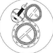

93
UNIVERSAL
RITZ FERRAMENTAS
HAND STICKS, HOT STICKS AND
TOOLS
B
VT-2 REINFORCED VT-3 REINFORCED VT-4 REINFORCED VT-5 REINFORCED VT-6 REINFORCED VT-7 REINFORCED VT-8 REINFORCED BB VT-1 REINFORCED REINFORCED MODEL WITH SLEEVE Catalog Reference Qty. of Section Retracted Length (m) Extended Length (m) Ø Base Section (mm) Bag Reference (optional) Approx. Weight kg lb VTT 29537-1/2 2 1.38 2.39 33 SLT-2/3 1.30 2.90 VTT 29537-1/3 3 1.50 3.55 37 SLT-4/5 1.80 4.00 VTT 29537-1/4 4 1.62 4.76 41 SLT-6/7 2.50 5.50 VTT 29537-1/5 5 1.76 6.00 45 SLT-8/9 3.20 7.10 VTT 29537-1/6 6 1.88 7.30 49 VTT17182-G05 4.00 8.90 VTT 29537-1/7 7 2.00 8.63 52 VTT17182-G06 4.90 10.90 VTT 29537-1/8 8 2.11 10.00 56 VTT17182-G07 6.10 13.50
Catalog Reference Qty. of Section Retracted Length (m) Extended Length (m) Ø Base Section (mm) Approx. Weight kg lb VTT 28790-1/9 9 1.44 8.94 60 5.50 12.10 Ø 6"

SECTIONAL HOT STICKS
The sectional hot stick is maintain the necessary insulation and safe distance for overhead line operations, by using universal tools, specially developed for the most diverse applications, such as:
- Knife-switches operation;
- Fuse-switches operation;
- Fuse cartridge removal and installation;
- Voltage testers handling;
- Installation and removal of temporary grounding equipment and hot line clamps;
- Life wire installation;
- Pruning trees;
- Cleaning of Networks;
- Light bulb replacement, etc.
Manufactured with RITZGLAS® tubes, fiberglass insulating tube, impregnated with epoxy resin. In order to facilitate its handling, storage and transportation more practical, the Sectional Hot Stick is composed of standardized elements, which are handle section, middle section(s) and top section, interchangeable and attached with quick spring-action locking pins, reinforced by metallic rings, beyond universal head in fused bronze, steel wing screw, pole sleeve reinforcement nylon and rubber base terminal.
The total length suitable for each working voltage class and/or height of work is obtained from the amount of its elements. There are two versions depending on their diameter/weight, being them, the standard model and the light model.
SECTIONAL HOT STICKS
94 HAND STICKS, HOT STICKS AND UNIVERSAL TOOLS RITZ FERRAMENTAS
VMR-S VMR-I VMR-P
B
Catalog Reference Section Ø (mm) Lenght (m) Approx. Weight Work Total kg lb VMR-S Tip 32 1.25 1.45 1.15 2.54 VMR/L-S Light tip 25 1.25 1.45 0.85 1.87 VMR-I Middle 38 1.25 1.45 1.20 2.65 VMR/L-I Light middle 32 1.25 1.45 0.80 1.76 VMR-P Handle 38 1.45 1.45 1.10 2.43 VMR/L-P Light handle 32 1.45 1.45 0.70 1.54
SECTIONAL HOT STICKS
For greater operational safety, observe the minimum distances according to the OSHA table.
Sectional Hot Sticks with Rigid Splice
The coupling between the elements is achieved through a rigid threaded joint that ensures mechanical stiffness and safety against accidental uncoupling The end element features a universal bronze head
95 HAND STICKS, HOT STICKS AND UNIVERSAL TOOLS RITZ FERRAMENTAS B
Catalog Reference Number of Sections Max. Length (m) Bag Reference (optional) Approx. Weight Handle Ø Middle Ø Tip Ø Total kg lb VMR-15 1 32 - - - - 1 1.25 VMR16824-1 0.95 2.09 VMR-15/L 1 25 - - - - 1 1.25 VMR16824-1 0.75 1.65 VMR-30 1 38 - - 1 32 2 2.70 VMR16824-2 2.25 4.96 VMR-30/L 1 32 - - 1 25 2 2.70 VMR16824-12 1.55 3.42 VMR-45 1 38 1 38 1 32 3 3.95 VMR10484-3 3.45 7.61 VMR-45/L 1 32 1 32 1 25 3 3.95 VMR10484-3 2.35 5.18 VMR-70 1 38 2 38 1 32 4 5.20 VMR16825-1 4.65 10.25 VMR-70/L 1 32 2 32 1 25 4 5.20 VMR16825-1 3.15 6.94 VMR-90 1 38 3 38 1 32 5 6.45 VMR16826-1 5.85 12.90 VMR-90/L 1 32 3 32 1 25 5 6.45 VMR16826-1 3.95 8.71
Catalog Reference Section Ø (mm) Working Length (m) Approx. Weight Aprox. kg lb FLV30834-1 Tip 32 1.45 1.16 2.56 FLV30833-1 Middle 32 1.45 1.04 2.29 FLV30832-1 Handle 38 1.45 1.32 2.91
B| VMR02579-1
OPERATIONAL HEADS
Grounding Clamp Heads
The grounding clamp heads are made of aluminum and have a universal locking system, adaptable to the hot sticks. They are used for grounding clamp operation through eyescrew locking.

Locking system via adjustable pressure half-ball.
Approx. Weight: 0.19 kg (0.42 lb)
| VMR07205-1

It has a galvanized steel rod for alignment and spring-loaded automatic clamping.
Approx. Weight: 0.25 kg (0.55 lb)
| RM4455-29B

Locking and release of the clamp is performed through a rotation of 180º twisting operation. It allows the articulation of the clamp, enabling the operation at different angles
Approx. Weight: 0.31 kg (0.68 lb)
| FLV11554-1
Head with Fall-Protection System
These heads are used for switching, installation, and removal of fuse holder cartridges without risks of accidental drops.
It has an automatic safety locking device (fall arrest) to ensure the safety of the electrician.

Hot-dip galvanized steel main body, safety lock and universal bronze alloy head.
Approx. Weight: 0.34 kg (0.75 lb)
| FLV13872-1

Main body in coated steel, with plastic and safety lock. Bronze alloy universal head.
Approx. Weight: 0.30 kg (0.66 lb)
96 HAND STICKS, HOT STICKS AND UNIVERSAL TOOLS RITZ FERRAMENTAS
Heads for Operation of Fuse Switches
Universal coupling, standard heads, adaptable to hot sticks
| VMR16483-1

Aluminum tilted head with circuit-breaker switching shaft and groove for fuse holder cartridge tongue
Approx. Weight: 0.25 kg (0.55 lb)
| VMR00884-1
27 mm

Stainless steel head with circuit-breaker switching shaft and groove for fuse holder cartridge tongue.
Approx. Weight: 0.29 kg (0.64 lb)
| VMR08974-1

Bronze head with shaft for circuit breaker switching
Approx. Weight: 0.11 kg (0.24 lb)
Big Eye Pin for HL Instalation
| FLV31217-1
| | RM4455-9
VMR01479-2 (liga de alumínio) (liga de bronze)


Disconnect head, used for opening and closing switches, enclosed cut-outs
Approx. Weight: 0.06 kg (1.46 lb) 0.17 kg (0.37 lb)
| VMR11560-1
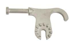
Stainless steel key disconnect head
Approx. Weight: 0.13 kg (0.29 lb)
| VMR03414-1

48 mm
Tool made of steel with anticorrosive surface treatment of electrolytic galvanization, and with universal head made of cast bronze alloy.
It is intended for the switching of keys by cutting circuit like knife keys and fuse keys through its maneuvering rod The shape of its body is designed to fit into fuse holder cartridge tongues, sailfish and ICC anchor hook. It can also be used for lifeline.
Approx. Weight: 0.28 kg (0.62 lb)
Device used to anchor the lifeline in DT concrete and wooden posts already drilled. The device is attached to the universal head for operation of switches (VMR03414-1) installed on the pole or telescopic hot stick and inserted into one of the holes in the pole, according to the height chosen for anchoring the lifeline.
Approx. Weight: 0.94 kg (2.07 lb)
32 45
100 mm

FLV31217-1
97 HAND STICKS, HOT STICKS AND UNIVERSAL TOOLS RITZ FERRAMENTAS B


UNIVERSAL POLES
It consists of a universal head (toothed) for easy, fast, and safe coupling of all universal tools, mounted with a thumbscrew, which comes with the stick. This enables the electrician to place the universal tool at angles of up to 90° to the pole
Depending on the configuration of the universal tool, a universal adapter (RM4455-84) can be installed between the pole and the tool to obtain any desired angle.
The universal stick, with attached rubber drip skirt, is designed for emergency wet operations (rubber drip skirts provide additional flow distance and change the water course to prevent it from dripping down the stick).
The rigid splice provides a convenient way of transport while maintaining proper lengths for the tasks to be performed.
All models have a rest strap (RH1760-5).
Please note that the bags for storage and carrying all universal sticks can be purchased separately.


UNIVERSAL POLES
Continues on next page 4
98 HAND STICKS, HOT STICKS AND UNIVERSAL TOOLS RITZ FERRAMENTAS
B
Catalog Reference Description Dimensions Storage (optional) Approx. Weight Ø (mm) Insulating Length (m) kg lb RH1760 With 1 head at one end, rubber base at the other and lace hook 32 2.40 FLV18339-3 1.75 3.86 RH1760-1 With 1 head on one end and rubber base on the other 32 1.79 FLV18339-2 1.30 2.87 RH1760-2 2 pole sections interconnected by a rigid splice, 1 universal head at one end, rubber base at the other and lace hook 32 2.29 FLV18339-1 2.10 4.63 RH1760-3 With 2 heads (1 at each end) and lace hook 32 1.76 FLV18339-2 1.70 3.75 RH1760-4 With 2 heads (1 at each end) and lace hook 32 2.37 FLV18339-3 2.00 4.41 RH1760-6 Sectional, 2 pole sections interconnected by a rigid seam, universal heads at the ends and lace hook 32 2.25 FLV18339-1 2.40 5.29 RH1760-10 With 2 heads (1 at each end) 32 2.98 FLV18339-4 2.20 4.85 RH1760-12 With 2 heads (1 at each end) 32 3.59 FLV18339-5 2.50 5.51 RH1760-14 With 2 heads (1 at each end) 32 4.20 FLV18339-14 2.85 6.28
Rigid splice
UNIVERSAL POLES
TIE STICKS
It has a variety of heads for different applications or even personal preferences of each electrician.
Hook poles (rotary or fixed) are suitable for doing and undoing laces using the eyes at their ends
The rotary blade pole is used to do and undo laces without eyes at their ends

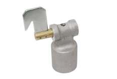

99 HAND STICKS, HOT STICKS AND UNIVERSAL TOOLS RITZ FERRAMENTAS B
Catalog Reference Description Dimensions Storage (optional) Approx. Weight Ø (mm) Insulating Length (m) kg lb RH1761 With 1 head at one end, rubber base at the other and 2 rubber drip skirts 32 2.40 FLV18339-3 1.60 3.53 RH1761-1 With 1 head at one end, rubber base at the other and 3 rubber drip skirts 32 2.40 FLV18339-3 1.70 3.75 RH1770 Folding, with 1 head at one end and rubber base at the other 32 2.30 FLV18339-1 2.00 4.41 RH1790-8 With 2 heads (1 at each end) 38 2.36 FLV18339-3 3.00 6.61 RH1790-10 With 2 heads (1 at each end) 38 2.97 FLV18339-4 3.30 7.28 RH1790-12 With 2 heads (1 at each end) 38 3.58 FLV18339-5 3.70 8.16 RH1790-14 With 2 heads (1 at each end) 38 4.19 FLV18339-14 4.10 9.04 RT403-0752 Sectional, where: 5.93 4.75 10.47 1 3m pole section 32 FLV18339-4 1 3m pole section 38 FLV18339-4 It contains 1 rigid splice at its center, 1 32mm universal head at its end and a rubber base in the 38mm section Catalog Reference Description Dimensions Storage (optional) Approx. Weight Ø (mm) Insulating Length (m) Total Length (m) kg lb RH1855-25 With rotary prong and rotary blade 32 2.36 2.48 FLV18339-3 1.90 4.19 RH1855-26 With rotary blade and universal head 2.51 FLV18339-3 1.90 4.19
Rotary Prong
Rotary Blade
FLEXIBLE INSULATED WRENCHES
It has a device to receive tools to tighten nuts in energized equipment.
The flexible socket installed on the pole gives the electrician increased flexibility when using this tool, especially at steeper angles. The male-type fixed socket at one end of the RH1891-2 and RH1891-3 poles allows the ratchet wrench (R066780) to be coupled for easy application of the required tightening torque
The universal head installed at one end of the RH1891-6 pole allows universal tools to be coupled
| Max. torque: 5.5 daN.m (40 ft -1 lb)
The RC403-2136 flexible insulated wrench has a female-type fitting at one end (which allows a R066780 wrench to be adapted) and a 1/2”male fitting at the other. With this, this tool is very versatile by allowing interchanging between two types of socket.
| Max. torque: 10 daN.m (75 ft -1 lb)
100 HAND STICKS, HOT STICKS AND UNIVERSAL TOOLS RITZ FERRAMENTAS B Catalog Reference Pole with Dimensions Storage (optional) Approx. Weight Ø (mm) Insulating Length (m) kg lb RC403-2136 Female-type flexible socket and fixed socket 38 2.36 FLV18339-3 2.30 5.07 RH1891-2 Male-type flexible socket and fixed socket 1.75 FLV18339-2 2.20 4.85 RH1891-3 Male-type flexible socket and fixed socket 2.36 FLV18339-3 2.60 5.73 RH1891-6 Flexible socket and universal head 2.36 FLV18339-3 2.70 5.95
RH1891-2
ACESSORIES
The hexagonal socket set consists of 11 units measured in inches or 10 units measured with the metric system and is intended to be tightened with the flexible wrench in hot line work.
Its square female socket can be adapted to many other hand socket wrenches or insulating socket poles.
Hex sockets are supplied in a case and arranged in measures in an orderly manner for easy selection.


INSULATING GRIP POLE
Designed to hold pliers or other hand tools so they can be used in hot-stick work.
They are available in two versions: including pliers or only the pair of grip poles.
These poles have a head to couple pliers or other compatible tool.


101 HAND STICKS, HOT STICKS AND UNIVERSAL TOOLS RITZ FERRAMENTAS B Catalog Reference Description Approx. Weight kg lb R066780 1/2”male and female manual ratchet socket wrench 0.50 1.10 RC403-1085 Set with 11 long steel sockets, measuring: ½”, 9/16”, 5/8”, 11/16”, 3/4”, 13/16”, 7/8”,15/16”,1”, 1.1/16”, 1.1/8” with case 2.16 4.76 RC403-1085M Set with 10 long steel sockets, measuring: 10 mm, 11 mm, 12 mm, 13 mm, 14 mm, 15 mm, 16 mm,17 mm, 18 mm, 19 mm, with case 2.40 5.29
RC403-1085M
R066780
Catalog Reference Description Dimensions Approx. Weight Ø (mm) Insulating Length (m) kg lb RH1861-1 Grip pole with pliers 32 1.18 2.00 4.41 RH1861-2 Grip pole only (pair) 1.80 3.97 RH1861-1 RH1861-2
With the removal of the ½”square insert, this tool becomes a female-type model


WIRE-HOLDING STICK
It is designed for hot-stick work to hold and position conductive cables and jumpers (mainly during sectioning operations), as well as to undo conductor laces in pin insulators
The lever on the bottom of the pole is responsible for locking the conductor in the jaw The knurled nut is designed to pre-adjust the opening of the upper head jaw according to the driver size. The two screws with knurled head are designed for locking the lever after mounting to the conductor.
The conductor clamp head can be preset in three positions (left, center and right), so the electrician can maneuver the conductor from favorable working angles. Its opening is designed to handle 6 AWG solid copper cables (Ø 4 mm) and even 1590 MCM ACSR aluminum cables (Ø 38 mm).


102 HAND STICKS, HOT STICKS AND UNIVERSAL TOOLS RITZ FERRAMENTAS
B
Catalog Reference Dimensions Conductor Ø (mm) Storage (optional) Approx. Weight Ø (mm) Insulating Length (m) Overall Length (m) Minimum Maximum kg lb RC403-3068 32 1.45 1.98 4 38 FLV18339-2 3.30 7.28 RC403-3069 1.89 2.58 FLV18339-3 3.70 8.16
ALL-ANGLE COG WRENCH
The swivel gear mechanism of the all-angle cog wrench allows the electrician to adjust the proper angle for socket placement and nut positioning in hot-stick operations
The fiberglass pole installed parallel to the tube, attached to the handle, is responsible for stabilizing the gear head, keeping it aligned, even when rotating the pole
The gear is complemented by a 1/2” square fitting to connect with the sockets that will operate the nuts
The gear angle can be pre-adjusted up to 140° in relation to the pole using the two wing nuts on the head
The gear mounting head is made of bronze alloy and the gears are made of special heat-treated steel This versatile hardware set is installed in the RITZGLAS® tube to ensure the required safety clearance and insulation.
WARNING
This pole is mechanically sized for nut adjustment only, with a maximum torque of 2.0 daN.m (15 ft-lb).
It must be tighten with the proper torque using the flexible socket pole


103 HAND STICKS, HOT STICKS AND UNIVERSAL TOOLS RITZ FERRAMENTAS B Catalog Reference Dimensions Storage (optional) Approx. Weight Ø (mm) Insulating Length (m) Total Length (m) kg lb RC403-0184 38 0.80 1.83 FLV18339-2 2.40 5.29 RC403-0185 1.41 2.44 FLV18339-3 2.90 6.39 RC403-0186 1.98 3.05 FLV18339-4 3.40 7.80 FLV01121-4 2.50 3.67 FLV18339-5 4.20 9.25
Insulating Length
RC403-0184

VOLT-AMMETER STICK
It has a head at its end that can be adjusted to be coupled to different clamp volt-ammeter models, provided their triggers are on their left side.
The head is plastic-coated to better accommodate the instrument and prevent surface damage. Once coupled to the pole, the clamp voltmeter is activated by a lever on its grip so it can be safely used due to the insulation of the RITZGLAS® tube and tie rod
In addition to one piece volt-ammeter poles, we have two folding models with the same function and also efficiency as they are easy to carry.
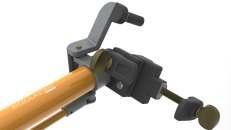


104 HAND STICKS, HOT STICKS AND UNIVERSAL TOOLS RITZ FERRAMENTAS B Catalog Reference Dimensions Approx. Weight Ø (mm) Insulating Length (m) Folded (m) Total Length (m) Instrument (mm) A B kg lb RH1968-8 32 1.60 - 2.51 38 to 115 23 to 60 2.35 5.18 RH1978-8* 1.60 1.25 2.51 2.80 6.17
* Folding
A B
TOOL RACK AND CROSSARM TOOL HANGER
The pole hanger is a very useful tool in the working area of electrician to rest poles in operation.
It is adjustable on crossarms, ranging in width from 95 to 114 mm (crossarm height is not important).
The paired pole rack is an alternative or complement for the canvas to arrange selected and properly prepared insulating poles in the workplace, thus avoiding their contamination from contact with the ground.
The twelve support rods and center mast are coated with plastic material to protect the poles from abrasion and have a capacity of 12 poles up to Ø 76 mm.
Tripod shoes are fully retractable for easy transport and storage of the rack.


105 HAND STICKS, HOT STICKS AND UNIVERSAL TOOLS RITZ FERRAMENTAS B Catalog Reference Description Approx. Weight kg lb RM1860 Tool hanger 0.95 2.09 RM4660 One tool rack 3.70 8.16 RM4660-E1 Two tool racks 7.40 16.32
RM1860
RM4660
B| RC403-0005
UNIVERSAL TOOLS
The universal tool series in this section has been carefully selected for interventions in energized installations using the universal insulating pole.
These tools are equipped with “toothed” universal heads for their perfect coupling with a universal pole, for hot-stick operations with absolute precision.
Each universal tool has its own properties and its main purpose is to replace manual operation, even if the work angles or positions are unfavorable

Cotter pin remover
It is used in disc insulator decoupling to displace the cotter pin when its eye is in the opposite direction of the structure.
Approx. weight: 0.38 kg (0.84 lb)
| RC403-0006

Cotter positioner
It is used in disc insulator couplings to insert the cotter pin in its locking position when its eye is in the opposite direction of the structure.
Approx. weight: 0.35 kg (0.77 lb)
| RC403-0011 Knocker

Due to the impact caused by its coil spring, this tool is designed for easy extraction of cotter pins when used in with cotter pullers, especially in tight spaces and adverse conditions.
Approx. weight: 0.27 kg (0.60 lb)
| RM4455-87

Ball socket adjuster
Designed to position the insulator ball socket during installation or removal. It is also used as an auxiliary tool during cradle installation in “V” chains and when installing tensioner poles
Approx. weight: 0.30 kg (0.66 lb)
| RC403-0126

Ball socket adjuster
Similar to the RM4455-87 ball socket adjuster, this tool is designed to handle objects up to Ø 69 mm.
Approx. weight: 0.32 kg (0.71 lb)
| RC403-0175

Ball socket adjuster (plastic coated)
The plastic coating prevents damage to disc insulators or poles during handling.
Approx. weight: 0.35 kg (0.77 lb)
106 HAND STICKS, HOT STICKS AND UNIVERSAL TOOLS RITZ FERRAMENTAS
| RC403-0177

All-angle pliers
Designed to hold nuts. fittings. or any other moving parts during intervention. Its wing nut allows preadjustment of the best desired angle
Approx. weight: 0.88 kg (1.94 lb)
| ATR10994-1

Multi-angled tongs with double jaw
It has the same application as RC403-0177, but it has a double jaw
Approx. weight: 1.00 kg (2.20 lb)
| FLV30755-1

Pliers for insulator
Its main application is to hold, guide and move the insulator chain during its installation or removal. Through the lifting eye, the pliers can be used to lift the chain from the ground to the installation site or the reverse operation (taking the chain from the job site and taking it to the ground).
Approx. weight: 1.00 kg (2.20 lb)
| RC403-0314

Conductor sander
Designed to clean the live conductor surfaces before installing grounding connectors or clamps, especially in oxidized copper conductors where cleaning by other methods is difficult
Approx. weight: 0.29 kg (0.64 lb)

Preform wire applicator
Specially developed for installation or removal of preform wire or lace on live conductors offering rotation control. which is difficult with other tools. Due to its small size. the RC403-0834 is recommended for top lacing work
Approx. weight: 0.10 kg (0.22 lb)
RC403-1416

Tie wire claw
Hand-shaped, acts as tweezers to manipulate wires or preformed wires during their installation on the conductor.
Approx. weight: 0.22 kg (0.49 lb)
| RC403-1417

Utility-head
Designed for different interruptions in energized installations, such as: installing or removing blocks, nylon straps, switches, etc.
Approx. weight: 0.24 kg (0.53 lb)
107 HAND STICKS, HOT STICKS AND UNIVERSAL TOOLS RITZ FERRAMENTAS B B A Catalog Reference Ø A (mm) Ø B (mm) RC403-0834 27 44.5 RC403-1071 35 76
| |
RC403-0834 RC403-1071
|
B| RM4455-2

Pin holder
Designed for the placement and removal of pins in insulator chains through its blade which holds the pin holder head firmly up to Ø 15 mm during handling
Approx. weight: 0.21 kg (0.46 lb)
| RM4455-5

Cut-Out Tool
Designed for handling the corona ring through its vice-type shape with plasticized hooks.
Max. aperture 75 mm | Ø max. 45 mm
Approx. weight: 0.78 kg (1.72 lb)
| RM4455-6

Ratchet wrench
Designed for the handling of bolts and nuts in energized installations through interchanging sockets. Equipped with a universal rotating screw at its end. it can be used with universal poles
Approx. weight: 0.69 kg (1.52 lb)
| RM4455-10
Chuck Blank

Designed to allow the installation of various tools through their welded fixings. making them universal for various interventions in energized installations
Approx. weight: 0.12 kg (0.26 lb)
| RM4455-12

Snapout Cotter Key Remover
Spring-action tool designed to remove cotter pins from insulators in energized installations when its head is directed towards the structure
Approx. weight: 0.17 kg (0.37 lb)
| RM4455-13

Snapout Disconnect
Spring-loaded action tool designed to open stuck disconnect or fuse switches.
Approx. weight: 0.20 kg (0.44 lb)
| RM4455-15

Locating Pin
It is used for easy introduction of pins and screws into metal structure fittings and insulator chains when the holes in these fittings need to be aligned.
Approx. weight: 0.32 kg (0.71 lb)
| RM4455-17

Fixed Prong Tie Stick Head
Designed for safe operations while performing wire lacings. preventing the end of the wire loop from coming loose and contacting the crossarm.
Approx. weight: 0.18 kg (0.40 lb)
108 HAND STICKS, HOT STICKS AND UNIVERSAL TOOLS RITZ FERRAMENTAS
| RM4455-18

Cotter Key Installing Tool
Designed for pin or hardware replacement through its clamps, which hold them tightly when they are out of reach of the electrician.
Approx. weight: 0.12 kg (0.26 lb)
| RM4455-19

Cotter Key Pusher
Designed to couple and uncouple insulators. The straight end allows the cotter pin to move from the inner shell housing, while the curved portion is used to push the cotter pin back into the housing
Approx. weight: 0.33 kg (0.73 lb)
| RM4455-22
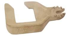
Ball Socket Adjuster
Shaped like a hook, it is designed to manipulate the socket position during the cotter pin installation or removal
Approx. weight: 0.34 kg (0.75 lb)
| RM4455-23

Hack Saw
Designed to cut components close to the live conductor, even at unfavorable angles
Approx. weight: 0.42 kg (0.93 lb)
| RM4455-26A

Pruning Saws
Designed to saw tree branches near energized installations.
Approx. weight: 0.36 kg (0.79 lb)
| FLV31800-1T

Saw for pruning with auxiliary hooks
With hooks at ends the tip to assist in removing cut branches.
Approx. weight: 0.46 kg (1.02 lb)
| RM4455-66

Saw handle
This tool acts as a handle for the pruning saw RM4455- 26A, for rubber glove work
Approx. weight: 0.20 kg (0.44 lb)
| RM4455-28

Screwdriver
Designed for the installation and removal of slotted head screws in energized installations.
Approx. weight: 0.12 kg (0.26 lb)
| RM4455-36

Link Stick Head
It is designed to hold light components or conductors during interventions in energized installations. It has an aperture capacity of 6 to 19 mm. Body edges are rounded to prevent damage to conductors
Approx. weight: 0.36 kg (0.79 lb)
109 HAND STICKS, HOT STICKS AND UNIVERSAL TOOLS RITZ FERRAMENTAS
B
B| RM4455-37

Chuck Blank
Designed for the coupling of various tools. with a firm attachment through a wing nut. making them a universal tool for the different energized interventions
Approx. weight: 0.14 kg (0.31 lb)
| RM4455-38

Mirror
Designed for inspections in energized installations not directly visible. The angle of the concave mirror can be preset. to give the electrician a better working position.
Approx. weight: 0.37 kg (0.82 lb)
| RM4455-39

Shepherd Hook
For handling and lifting insulator chains. Its articulation is designed to maintain alignment with the insulator at all times
It is also used as a support during interventions in energized installations. such as: pole or yoke installations.
Approx. weight: 0.30 kg (0.66 lb)
| RM4455-40

Fixed Blade Tie Stick Head.
It has a blade with a 60° tilt in relation to the pole. for lace wire handling.
Provided with deep V-shaped for easy wire extraction. even in hard to reach places
Approx. weight: 0.20 kg (0.44 lb)
| RM4455-46

Flexible Wrench Head
Designed for fitting to 1/2” standard sockets when installing or removing bolts or nuts.
Approx. weight: 0.42 kg (0.93 lb)
| RM4455-50

Skinning Knife
Allows cutting objects or removing conductor insulation in energized installations.
Approx. weight: 0.11 kg (0.24 lb)
| | RM4455-63 RM1889

Conductor Cleaning Brush

It has steel bristles for excellent pressure around the conductor during cleaning. Available in models RM4455-63. with a universal socket for coupling to a universal stick. and RM1889. with a grip for manual use (when used with rubber insulating gloves). Steel bristles may be purchased for replacement in packages with 10 units: (RM1899).
Approx. weight: 0.17 kg (0.37 lb) 0.36 kg (0.79 lb)
| RH4455-64

Extension with drip skirts
This tool is designed for coupling on insulating poles for use in emergency situations under rain.
Approx. weight: 1.10 kg (2.42 lb)
110 HAND STICKS, HOT STICKS AND UNIVERSAL TOOLS RITZ FERRAMENTAS

Insulator Forks
Designed to hold the insulator during its installation or removal
With a pre-set angle on the wing nut and by turning the screw. the fiber jaws are adjusted from 76 to 108 mm (3” to 4-1/4”) on model RM4455-67. and 57 to 89 mm (2 1/4” to 3-1/2”) on model RT403-1101.
Approx. weight: 1.06 kg (2.34 lb)
| RM4455-69

Rotary Prong Tie Stick Head
It has free rotary prong at its ends to do and undo laces.
Approx. weight: 0.30 kg (0.66 lb)
| RM4455-70

Rotary Blade Tie Stick Head
A tool with a V-shaped steel blade and free swivel on its axis.
It is used to undo laces without eye at its end.
Approx. weight: 0.26 kg (0.57 lb)
| RM4455-71

Pointed Disconnect
A head used for circuit breaker switch operation.
Approx. weight: 0.09 kg (0.20 lb)
| RM4455-72

Conductor Gauge
It is designed for fast and accurate gauge measurement of ACSR. solid or multi-stranded copper conductors. for 4 Cu up to 4/0 ACSR.
Approx. weight: 0.08 kg (0.18 lb)
| RM4455-77

Fuse Puller
With universal fit. it is designed to install. mobilize. or remove Ø 13 to 38 mm fuse switch cartridges in energized installations by rotating the universal pole
The cartridge puller angle can be pre-set using the wing nut.
Approx. weight: 0.97 kg (2.14 lb)
| RM4455-78

Fuse Puller
Similar in application to model RM4455-77. this tool has an aperture capacity of 25 to 64 mm.
Approx. weight: 1.0 kg (2.20 lb)
| FLV03811-3

Fuse Puller
Designed to install mobilize. or remove Ø 30 to 90 mm fuse switch cartridges in energized installations by rotating the universal pole.
Approx. weight: 1.40 kg (3.09 lb)
111 HAND STICKS, HOT STICKS AND UNIVERSAL TOOLS RITZ FERRAMENTAS B | | RM4455-67
RT403-1101

BAerosol can holder
Intended for safe application of paint and lubricant to energized equipment in hard-to-reach places or insecticide to bee and wasp nests. on poles and crossarms
Optional: CPR-30485 - Protective Cover for Aerosol Applicator
Approx. weight: 0.21 kg (0.46 lb)
| RM4455-79

Spiral Disconnect
It is designed for several tasks. such as: - opening yoke locks to release trunnions or adjustable sleeves on tensioning poles; - assisting in installing energized side yokes; - cable tensioner mounting and removal.
Approx. weight: 0.18 kg (0.40 lb)
| RM4455-80

Tree and Rope Hook
Designed for pushing/pulling tree branches out of the work area near energized installations or to untangle ropes.
Approx. weight: 0.15 kg (0.33 lb)
| RM4455-82

All Purposes Cotter Key Tool
Specially designed for installing and extracting cotter pins in insulator anchor chains
It has guiding slots for the cotter pin during mounting.
Approx. weight: 0.09 kg (0.20 lb)
| RM4455-84

Universal adapter
It is provided with a thumbscrew to couple to a universal head. allowing the change of the installation angle of a tool.
Approx. weight: 0.11 kg (0.24 lb)
| RM4455-85

Hammer
Designed for you to strike hard in energized installations to move them.
Approx. weight: 0.42 kg (0.93 lb)
| RM4455-86

Vise Grips Holder
Designed to be a temporary anchor for the ends of cut conductors during maintenance to prevent them from becoming loose
Approx. weight:0.13 kg (0.29 lb)
112 HAND STICKS, HOT STICKS AND UNIVERSAL TOOLS RITZ FERRAMENTAS
| RC403-2270
| RM4455-88

Bolt Head Wrench
It acts as a fixed wrench for Ø 3/4” and 5/8” bolts. preventing them from turning when the nut is moved with the RM4455-89 ratchet wrench and RC403-1085 and RC403-1085M multi-angle sockets
Approx. weight:0.42 kg (0.93 lb)
| RM4455-89

Ratchet Wrench
Designed to tighten 5/8”square nuts on energized installations hardware. regardless of thread length.
Approx. weight:1.19 kg (2.62 lb)
| FLV16165-1

Universal Extension Device
This tool is designed for the extension. in certain cases. of other universal tools in hard to reach places. Approx. weight:0.15 kg (0.33 lb)
| RM4455-92

Conductor Cleaning Brush
It has a semitubular shape with Ø 64 mm external length and a swivel head with universal fit for use for coupling to universal poles. Designed to clean the whole circumference of an energized conductor
Approx. weight:0.53 kg (1.17 lb)
| RM4455-93

Conductor Cleaning Brush
Similar to model RM4455-92 (Ø 64 mm). for manual use with the aid of insulating gloves for increased safety.
Approx. weight:0.30 kg (0.66 lb)
| | RC403-0320 RC403-0450 (Ø 64 mm external) (Ø 76 mm external)

Conductor Cleaning Brush
Also similar to the RM4455-92 model. it has a plastic coated steel handle for better grip for electricians who should wear insulating gloves during handling
Approx. weight:0.22 kg (0.49 lb)
0.45 kg (0.99 lb)
| RM4455-96

Cotter key Puller
It is designed for easy partial extraction of the cotter pin through its “petal” shape that. by moving the lever. gently extracts the cotter pin that is perpendicular to the structure.
Approx. weight:0.28 kg (0.62 lb)
113 HAND STICKS, HOT STICKS AND UNIVERSAL TOOLS RITZ FERRAMENTAS B
B| RM4455-97

Tool for “W” keys
Designed for replacement of W-type cotter pins (commonly used in Europe and Japan) using its slot.
Approx. weight:0.22 kg (0.49 lb)
| RM4455-100

Flexible Universal Adapter
This tool is designed to rotate another universal tool in series with it. even at an angle when coupled to a universal pole or hot stick.
Approx. weight:0.72 kg (1.59 lb)
| RM4455-102

Pin Installer
This tool allows the placement of pins in insulator chains through its three tightly grasping clamps.
Approx. weight:0.40 kg (0.88 lb)
| RM4455-103

Cotter Key Installing Tool
This tool is designed for the installation of angled cotter pins in the insulator chains through its multisnap device
Approx. weight: 0.26 kg (0.57 lb)
| FLV16148-1

Universal Hook
This tool is designed for handling objects up to Ø 64 mm.
Approx. weight:0.34 kg (0.75 lb)
| FLV16159-1

Rubber Coated Hammer
Designed to strike equipment in energized installations to move them.
Approx. weight:0.40 kg (0.88 lb)
| FLV11042-1

Boat-hook Tool
Used by firefighters to break glass. roofs. etc. to clear places that need to be accessed. such as buildings. homes. sheds after a fire. reducing accidents
Approx. weight:0.85 kg (1.87 lb)
| FLV29611-2

Spacer mounting head
Tips made of steel in order to allow a certain flexibility so that the electrician can position them in the best possible way during use. Coated in red plastisol to improve visibility from a distance from the tool
Approx. weight: 0.20 kg (0.44 lb)
114 HAND STICKS, HOT STICKS AND UNIVERSAL TOOLS RITZ FERRAMENTAS
CUTTERS
The Ritz Cutters models are manufactured with RITZGLAS® insulating tube, providing safety to the electrician during cutting operations. The blades are forged from special steel and properly tempered, resulting in enhanced performance and unparalleled durability.
| HINGED-TYPE LEVER CUTTER
Designed for low-effort cutting and specifically tailored for interventions using the contact work method, the cutter is perfect for cutting aluminum cables with steel core (CAA), aluminum cables (CA), and copper cables up to 1/0 or Ø 10.11 mm.

| SIMPLE HANDLE CUTTER
Developed for cutting aluminum 556 MCM ACSR cables with a diameter of up to Ø 23.5 mm. Engineered for cuts that require minimal effort, this equipment is exclusively intended for interventions using the contact work method

115 HAND STICKS, HOT STICKS AND UNIVERSAL TOOLS RITZ FERRAMENTAS B Catalog Reference Maximum Conductor Size Dimensions Approx. Weight Ø (mm) Total Length (m) kg lb FLV02818-2 1/0 CAA Ø 10.11 mm 32 0 72 2.20 4.91 Catalog Reference Maximum Conductor Size Dimensions Approx. Weight Ø (mm) Total Length (m) kg lb FLV19245-1 556 MCM CAA (ACSR) Ø 23.5 mm 38 0 84 2.50 5.51
FLV02818-2
FLV19245-1
| LEVER TYPE WIRE CUTTERS
Engineered for precise cutting of CAA, CA, and copper aluminum cables. Its lever, coated with plastic, features a reinforced fiberglass strut that activates the blades, providing the operator with additional mechanical force during conductor cutting.
Insulating Length

| RATCHET CABLE CUTTERS
Designed for cutting aluminum CAA and CA cables, the ratchet cable cutters offers the capability to cut larger gauge cables, such as the 556 MCM CAA Ø23.5 mm. The structure of these cutters, equipped with a plastic roller system, ensures smooth operation as it glides over the RITZGLAS® tubing The articulation of the reinforced fiberglass struts also contributes to smooth and effective functioning.
Insulating Length


116 HAND STICKS, HOT STICKS AND UNIVERSAL TOOLS RITZ FERRAMENTAS B Catalog Reference Maximum Conductor Size Pole Dimensions Approx. Weight Ø (mm) Insulating Length (m) Total Length (m) kg lb RC403-1382 556 MCM CAA Ø 23.5 mm 38 0.79 1.97 5.20 11.46 RC403-1384 556 MCM CAA Ø 23.5 mm 38 1.40 2.58 5.50 12.13 Catalog Reference Maximum Conductor Size Pole Dimensions Approx. Weight Ø (mm) Insulating Length (m) Total Length (m) kg lb RH1871-4 1/0 CAA (ACSR) Ø 10.11 mm 32 0.71 1.45 3.45 7.50 RH1871-6 1/0 CAA Ø 10.11 mm 32 1.16 2.00 4.00 8.82 RH1873-4 4/0 CAA Ø 14.31 mm 38 0.71 1.45 5.40 11.90 RH1873-6 4/0 CAA (ACSR) Ø 14.31 mm 38 1.16 2.00 6.00 13.20 RH1875-4 336,8 MCM CAA Ø 18.83 mm 38 0.71 1.45 6.00 13.20 RH1875-6 336,8 MCM CAA Ø 18.83 mm 38 1.16 2.00 6.80 15.00
TREE TRIMMERS
Designed for precise tree branch cutting, the tree trimmers is ideal for areas near electrical installations, ensuring efficiency and safety during intervention.
With forged and sharpened steel blades, the tree trimmers can cut branches up to Ø1". Its pulley system provides a 3x1 mechanical advantage, making the operator's work easier. For example, a force of 4.5 daN (10 lb) on the rope will result in a force of 13.5 daN (30 lb) on the blades
The tree trimmers has a Ø 1/4" rope with a length of 7.60 m. Additionally, it features a universal attachment near the blade, allowing for the installation of a pruning saw for branches
The tree trimmers offers versatility, enabling attachment to complementary poles through the universal head (FLV31519-1) or the quick coupling system (RH2106 - FLV21137-1), ensuring efficient work while maintaining the minimum safety distance.

| RM4455-26A
Pruning Saws
Designed to saw tree branches near energized installations. Approx. weight: 0.36 kg (0.79 lb)
| FLV31800-1T
Saw for pruning with auxiliary hooks
With hooks at ends the tip to assist in removing cut branches
Approx. weight: 0.46 kg (1.02 lb)

117 HAND STICKS, HOT STICKS AND UNIVERSAL TOOLS RITZ FERRAMENTAS B Catalog Reference Pole with Dimensions Approx. Weight Ø (mm) Working length (mm) kg lb FLV31519-1 Branch pruner with universal head 32 569 1.30 2.86 RH2106 Branch pruner with quick coupling 32 1978 2.50 5.51 FLV21137-1 Branch pruner with quick coupling 32 1315 2.18 4.80
W ork length with quick coupling W ork length with universal head


CUTTING WIRES
A tool used for quickly and safely disconnecting consumers, cutting illegal connections, and in situations of broken conductors from the ground, attached to the hot stick
With precise and fast cutting wires designed to cut aluminum, copper and multiplexed cables, the Cutting Wires allows work to be done more efficiently and safely
The Lever-operated Wires Cutter model features an insulating protective cover for the blades, RITZGLAS® insulating tube (nominal voltage: 1 kV), an insulating actuating rod, aluminum head with universal fitting, a lever for operation, and a pull rope.
118 HAND STICKS, HOT STICKS AND UNIVERSAL TOOLS RITZ FERRAMENTAS
B
Catalog Reference Description Cutting Opening (mm) Cut Conductors Up To Approx. Weight kg lb FLV17844-1 Universal tool head for cutting wires 15 35 mm² 2 AWG 0.30 0.66 Catalog Reference Description Cutting Opening (mm) Cut Conductors Up To Approx. Weight kg lb FLV31413-1 Lever-operated wires cutter 13 35 mm² 2 AWG 1.17 2.58
KITE BUSTER TOOL
Practical for the removal of kites and intertwined wires in the electric networks, especially in urban areas, situations that cause serious risks to system operation and negatively affects the visual aspect.
This tool is used at the end of the hot stick through by connecting it to the universal head
It was built with Ø 25 mm x 300 mm RITZGLAS® tube in total length and has steel cross pins in its body to tie the wires attached to the power grid
The upper end of this tool can be coupled with other head models for cutting and removing objects from electrical networks

The sharp blade head (FLV09311-1) has universal fitting for hot stick operation, an accessory for Kite buster tool where could be attached to the top end of this tool. There is a sharp cutting blade. Upper side blade and downside blade for enhanced performance.
The universal sharp blade head (FLV30173-1) has its own characteristics for cutting and removing objects from the network. Made with universal aluminum alloy head and “U” shaped blade, the blade edge internal for easy cutting.


119 HAND STICKS, HOT STICKS AND UNIVERSAL TOOLS RITZ FERRAMENTAS B Catalog Reference Description Approx. Weight kg lb FLV13907-1 Kite buster tool 0.31 0.68 ACCESSORY Catalog Reference Description Approx. Weight kg lb FLV09311-1 Flange Universal Head 0.16 0.35 FLV30173-1 Universal Head with blade 0.11 0.24
FLV13907-1
FLV09311-1
FLV30173-1

CONDUCTOR STRIPPER
| FVR BXQ-Z-40A
Tool used to remove the polymeric protective cover on protected copper and/or aluminum conductors, used in electricity distribution networks, without damaging the conductors. Suitable for shielded conductors with a diameter ranging from 14 to 40 mm, with a coating thickness of up to 6 mm.
The cutting blade is made of alloy steel, where it is sharpened after being ground and heat treated. It is an easy-to-remove component (for replacement or sharpening) and its positioning in the tool facilitates the operation of stripping the conductor, allowing the operation to be visualized.
The stripping operation can be carried out at the ends and in the middle of the conductor, simply positioning the tool in the desired location. It is an easy-to-use tool and guarantees an excellent quality of finish.
Approx. weight: 1.00 kg (2.20 lb)
MANUAL HYDRAULIC CABLE CRIMPING

Tool developed for crimping copper or aluminum alloy connectors, splices, and terminals.
It features a two-stage pumping system with fast advance to expedite the crimping process The articulated die holder head is made of forged steel and has a 180° articulation angle, compatible with U-type and hexagonal dies, manufactured for use in 12 ton tools
TECHNICAL CHARACTERISTICS
- Crimping force: 12 tons;
- Maximum crimping pressure: 700 kgf/cm²;
- Crimping section: 35-300 mm²;
- Crimping type: Compatible with U-type and hexagonal dies;
- Oil capacity: 145 cm³;
- Stroke: 32 mm;
- Actuation system: Fiberglass-insulated tubes that withstand a voltage of 20 kV for 5 minutes;
- Packaging: Plastic case.
120 HAND STICKS, HOT STICKS AND UNIVERSAL TOOLS RITZ FERRAMENTAS B
Catalog Reference Description Approx. Weight kg lb FVR 410-12 Manual hydraulic crimping pliers without dies kit 8.24 18.17
POLE HANDLING TOOLS
It is made with RITZGLAS® tube (Ø 51 mm) and designed to rotate poles or other cross-sections (hexagonal, square) made of wood, metal or concrete for mounting positioning
| RC305-0021
It has a 48 mm wide and 1.83 m long nylon strap and has a capacity of up to 3402 daN (7500) lbf tensile strength, firmly gripping the posts up to Ø 480 mm, including smooth surfaces
Insulate length: 1 22 m;
Approx weight: 2 90 kg (6 39 lb)
| RC305-0008
It has an articulated galvanized steel hook at its fixing end which is also adjustable So it can grab wooden posts of different diameters
Insulate length: 0 91 m;
Approx. weight: 3.40 kg (7.50 lb)
| RC200T
It has jaws to grab poles from Ø 180 to 406 mm.
Insulate length: 0.85 m;
Approx. weight: 6.00 kg (13.22 lb)

RC305-0021

RC305-0008

121 HAND STICKS, HOT STICKS AND UNIVERSAL TOOLS RITZ FERRAMENTAS B
RC200T

AUXILIARY STICK FOR POSITIONING ON UTILITY POLES INSTALLATION
A tool to aid in the movement of utility poles composed of rotary drive stem, made of Ø 32 mm RITZGLAS® insulation tube, with non-slip groving, fixed threaded head, mobile head and support shoe. It also has polyester strap with protector, triggered by ratchet, which enables the attachment of the tool to the utility pole
Stick to assist in the movement of utility poles, during their installation and removal, with the purpose of maintaining the electrician safe, avoiding the risk of electric shock due to accidental utility pole contact with the energized network. The insulation stem holds the electrician away from the utility pole and allows through rotary movements, the repositioning of the tool.

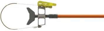

122 HAND STICKS, HOT STICKS AND UNIVERSAL TOOLS RITZ FERRAMENTAS B
Catalog Reference Insulating Length (mm) Total Length (mm) (A) Utility Pole Work Diameter (mm) Approx. Weight kg lb FLV30841-1 650 1710 250 a 300 7.65 16.86 Insulating Length Total Length A
RESCUE HOOK
Designed for electrical accident rescue in installations up to 34.5 kV, this pole with anatomically designed hooks ensures the required safety clearance and insulation, making emergency and adverse interventions practical, quick, and safe
It is built with a RITZGLAS® tube, the same used in hot line maintenance tools. It has decreased weight, high mechanical strength, and excellent dielectric strength, essential characteristics for easy handling and total safety.
The RITZGLAS® Rescue Stick should only be used to move the victim away from energized points. Removing the victim should be sufficient for safe first aid.


123 HAND STICKS, HOT STICKS AND UNIVERSAL TOOLS RITZ FERRAMENTAS B Catalog Reference Ø (mm) Rated Work Capacity Length (m) Approx. Weight daN lb Total kg lb FLV09429-1 32 200 440 2.25 2.70 5.95
0.33 m 0.14 m Total Length
Arm, leg, or feet pulling hook
Body pulling hook
MEASURING STICK AND EXTENSION
Designed to measure lengths and gaps up to 3 m in energized systems when minimum recommended safety distances cannot be maintained.
It comprises of RITZGLAS® insulating poles with alternating 10 cm markings, in orange and black colors, hooks, and universal connections made of aluminum and bronze alloy.
It has a versatile design, enabling measurements at angles.
Easy to handle, it can be used with the rubber glove method or with a hot stick connected to its universal head.
For measurements of lengths over 3 m, the FLV16146-1 extension must be coupled to the set.
124 HAND STICKS, HOT STICKS AND UNIVERSAL TOOLS RITZ FERRAMENTAS B Catalog Reference Description Ø (mm) Total Length (m) Approx. Weight kg lb FLV16140-1 Measuring stick 9.50 3.00 0.80 1.76 FLV16146-1 Extension 16.00 2.00 1.00 2.20
FLV16140-1
FLV16146-1

Application, Handling and Conservation . . . 127 Pole Covers . . . . . . . . . . . . . . . . . . . . . . . . . . . . . . . 129 Round Covers . . . . . . . . . . . . . . . . . . . . . . . . . . . . . 130 Crossarm Covers . . . . . . . . . . . . . . . . . . . . . . . . . . 131 Pole Top Cover . . . . . . . . . . . . . . . . . . . . . . . . . . . . 132 Fuse-Switch and Switch Cover . . . . . . . . . . . . . 133 Conductor, Pin and Disc Insulator Covers 136 Secondary Conductor Cover (LV) . . . . . . . . . . 136 Compact System Cover. . . . . . . . . . . . . . . . . . . . 137 Transformer Bushing Cover . . . . . . . . . . . . . . . . 137 Insulating Covers for Maintenance Works on Energized Substations 138 Permanent Covers. . . . . . . . . . . . . . . . . . . . . . . . . 140 Insulated Rubber Blanket 142 Flexible Cover for Conductors . . . . . . . . . . . . . 143 Rubber Insulating Gloves and Sleeves 145 Removable Protective Cover. . . . . . . . . . . . . . . 148 COVER-UP AND INSULATING RUBBER GROUP C Access our site.
COVER-UP AND INSULATING RUBBER GROUP C
APPLICATION, HANDLING AND CONSERVATION
Hot line protective covers are one of the main protective equipment for interventions in low and medium voltage energized installations.
They are designed to electrically protect the entire work area in order to prevent accidental phase-to-phase or phase-to-ground contacts during service
They are used in rubber glove work in energized lines and must be installed with rubber insulating gloves or with from a distance, as they have metallic brackets (eyebolts) for hot sticks
They should only be used by suitably trained electricians for hot line work and requires the following basic rules to be observed:
1. Under no circumstances should the electrician touch the covers except with rubber gloves Therefore, the electrician should always be aware of his/her position in relation to them to avoid accidentally touching them..
This rule is valid for any other Cover used to protect energized parts
127 COVER-UP AND INSULATING RUBBER RITZ FERRAMENTAS C
2. Protective covers for poles, crossbars, horizontal supports, C-support, and round covers are designed to prevent accidental contact of energized conductors or cable ties with grounded surfaces of the structure.
3. Protective covers should be handled with care to avoid breaking, cracking, or scratching and should always be kept clean and dry.
4. Each protective cover should be carefully inspected prior to use for cracks, deep scratches, deformation, or other damage, and to check that they are clean and dry
If necessary, it must be cleaned only with cotton fabrics. If dirt cannot be completely removed, use mild soap and water
5. Unlike permanent protective covers, which will be addressed at the end of this group, protective covers are designed for temporary use to perform a variety of hot line maintenance tasks, and must be removed after the service.
CAUTION
Hot line protective covers are designed for a wide variety of power system maintenance situations, and we provide appropriate covers for each type of equipment for increased efficiency and safety
The electrician must carefully select the most suitable covers and in the necessary amounts, to avoid dangerous improvisations before any task.
A visual inspection of the covers for cracks, deep scratches, dirt, deformations, etc. is imperative for all hot line teams, because user safety depends on perfect equipment maintenance. When in doubt, the covers must not be used and sent for electrical testing.
TECHNICAL CHARACTERISTICS
Hot line protective covers are made of high dielectric, UV, and ozone resistant thermoplastic.
Its orange color allows excellent visualization of the area under intervention.
Protective covers for hot stick work have metallic brackets for stick operation.
128 RITZ FERRAMENTAS COVER-UP AND INSULATING RUBBER C
POLE COVERS
It is used for insulating protection for pole mounting or changing operations
They have internal ribs, an important detail to prevent surface abrasions during handling, decisively extending their useful life, with polypropylene rope handles for easy mounting and removal with insulating gloves
Models with 1200 and 1800 mm lengths have a nylon button to couple two or more units to protect a longer pole length.


129 COVER-UP AND INSULATING RUBBER RITZ FERRAMENTAS C
A C B polypropylenerope COVER FOR POLES UP TO Ø 300 mm Catalog Reference Dimensions (mm) Approx. Weight A B C kg lb RC406-0028 300 300 ~115 1.15 2.54 RC406-0029 600 2.35 5.18 RC406-0030 1200 4.85 10.69 RC406-0000 1800 7.20 15.87 Rated voltage 36.6 kV (phase/phase) COVER FOR POLES UP TO Ø 230 mm Catalog Reference Dimensions (mm) Approx. Weight A B C kg lb RM4937-1 300 230 ~195 1.00 2.20 RM4937-2 600 1.95 4.30 RM4937-4 1200 3.95 8.71 RM4937-6 1800 5.95 13.12 Rated voltage 36.6 kV (phase/phase)
FOR POLES UP TO Ø 150 mm Catalog Reference Dimensions (mm) Approx. Weight A B C kg lb RC406-0548 300 150 ~115 0.70 1.54 RC406-0549 600 1.20 2.65 Rated voltage 36.6 kV (phase/phase)
COVER


ROUND COVERS
Due to their versatility, these covers are used to protect pole ends, braces, crossarm, lightning arresters, etc
As its application is not specific, each use deserves special care in order to ascertain the real protection that the cover offers
It has a polypropylene rope strap for easy installation and removal with insulating gloves.
ROUND COVER TO Ø 100 AND 150 mm
130 RITZ FERRAMENTAS COVER-UP AND INSULATING RUBBER C A B C
Catalog Reference Dimensions (mm) Approx. Weight A B C kg lb COB11176-1 300 100 ~196 0.40 0.88 COB11176-2 600 0.80 1.76 COB11176-3 900 1.20 2.65 COB11176-4 1200 1.60 3.53 COB04487-1 300 150 ~135 0.50 1.10 COB04487-2 600 0.90 1.98 COB04487-3 900 1.30 2.87 COB04487-4 1200 1.80 3.97
Rated voltage 26.4 kV (phase/phase)
CROSSARM COVERS
Its main application is to prevent the contact of cable ties with the crossarm in pin insulator or post insulator replacement operations
They can also be used to hold the temporary jumper or conductor over the crossarm. Conductors must be protected with an appropriate covers
Three models are available, one for crossarms with pin insulator and others for crossarms with post insulator


Crossarm End Cover
It is used to protect crossarm ends against accidental contact with the cable tie during mounting or removal.
With the rubber glove method this cover also helps to prevent the electrician from contacting the earth potential.
The RC406-0102 can be used on crossarms with pin or post insulators as it has a bolt groove for double crossarm mounting


131 COVER-UP AND INSULATING RUBBER RITZ FERRAMENTAS C
Catalog Reference Description Length (mm) Approx. Weight kg lb RM4933 With pin insulator 610 1.45 3.20 COB11173-1 With post insulator 570 1.50 3.31 COB11173-2 Short type, with post insulator 430 1.10 2.43 Rated voltage 36.6 kV (phase/phase) Catalog Reference Description Approx. Weight kg lb RC406-0102 Crossarm end cover 1.25 2.75 COB14780-1 Crossarm end cover 0.71 1.57 COB10765-1 Cover for disconnect switch housing 0.68 1.50 Rated voltage 36.6 kV (phase/phase)
RM4933
COB11173-1
COB11173-2
RC406-0102
COB10765-1
COB14780-1

POLE TOP COVER
| Rated voltage 36.6 kV (phase/phase)
| RC406-0097
It is used to protect pole tops during cable tie installation and removal operations
It adapts to poles up to Ø 254 mm. It has an elastic rope for better mounting Approx. Weight: 2.10 kg (4.63 lb)


FUSE-SWITCH AND SWITCH COVERS
It is used as protection in structures with fuse or disconnect switches, and can be installed using rubber glove and hot-stick methods.
The RC406-0009 cover is secured by a pin that locks it behind the insulator and rests on the metal switch bracket.
Model COB28494-1 is wrapped around the two insulator shrouds, which are compressed in place.
The COB13345-1 cover is used for insulating protection between the disconnect switch housing and live parts during jump installation and removal operations or other work on the switch. Designed for 15 and 23 kV networks, it consists of two flat plates, which, when half-open, can be wrapped around the base of the insulators and locked by insulating nuts
132 RITZ FERRAMENTAS COVER-UP AND INSULATING RUBBER C
COB28494-1 COB13345-1 RC406-0009 Catalog Reference Description Rated Voltage kV (phase/phase) Approx. Weight kg lb RC406-0009 Protective cover for fuse switch 26.4 2.80 6.17 COB28494-1 Protective cover for disconnect switch 36.6 2.90 6.39 COB13345-1 Protective cover for disconnect switch housing (365 x 880 mm) 26.4 2.00 4.41
CONDUCTOR, PIN AND DISC INSULATOR COVERS
Conductor Cover
It provides a greater protection area in energized parts and therefore the most commonly used in hot line work
Available in many models to suit various types of electrical installations with rated voltages up to 48.3 kV.
Their ends are provided with a male/female fitting, for firm connections with two or more units or other models, such as pin insulator covers and disc insulator covers
Specifically, RP406-0184/RC406-0181GA/RC406-0514GA also allow connections with rubber conductor covers
The metal eye ring clips are designed to mount the covers on the network with a hot-stick
Specifically for covers RP406-0184 and COB03335-1, this is an option for users who wish to mount them using the rubber glove method
With a universal head mounted at the end of this stick, the mounting angle of the cover can be pre-adjusted.
Pin Insulator Cover
They are designed to protect an energized conductor next to a pin or post insulator, and are normally used with conductor covers to which they can be coupled through standard fittings.
One of its sides can be adjusted for better a fit in many crossarm widths.
There are several models available, which vary according to application and operating voltage.
Some have metallic brackets for hot-stick work, and others have no metallic brackets for rubber glove work.
Disc Insulator Cover
It establishes protection of live parts near disc insulators in anchor chains.
They have fittings on both ends, one to couple to the insulator and the other to couple to the conductor cover. Some are equipped with a metallic bracket for the hot-stick work and an elastic strap for better mounting of the edges
Applicable for both conventional and polymeric insulators
133 COVER-UP AND INSULATING RUBBER RITZ FERRAMENTAS C


134 RITZ FERRAMENTAS COVER-UP AND INSULATING RUBBER C RP406-0184 RC406-0182L RC406-0164
SET CONDUCTOR / PIN INSULATOR / DISC INSULATOR Catalog Reference Application Description Approx. Weight kg lb RP406-0184 Conductor For rubber glove work For conductors up to Ø 25 mm Approx. length 1.560 mm 1.50 3.31 RC406-0181GA Conductor For hot-stick work For conductors up to Ø 25 mm Approx. length 1.560 mm 1.60 3.50 RC406-0182 Pin Insulator 153 mm Height with metallic bracket for hot stick 1.10 2.43 RC406-0182L Pin Insulator 229 mm Height with metallic bracket for hot stick 1.20 2.65 RC406-0164 Disc Insulator Protection for discs up to Ø 254 mm 4.30 9.48 Rated voltage 26.4 kV (phase/phase)
bracket for hot-stick COB11400-1
SET
INSULATOR / DISC INSULATOR Catalog Reference Application Description Approx. Weight kg lb COB03335-2 Conductor For rubber glove work For conductors up to Ø 25 mm Approx. length 1.560 mm 1.20 2.65 RM4946-1 Conductor Plastic bracket for hot-stick work For conductors up to Ø 25 mm Approx. length 1.560 mm 1.35 2.98 RM4946-2 Conductor Metallic bracket for hot-stick work For conductors up to Ø 25 mm Approx. length 1.560 mm 1.38 3.04 RM4947 Pin Insulator With Metallic bracket 0.70 1.54 COB11400-1 Pin Insulator Dead end, polymer, porcelain rigid and disc insulators up to Ø 160 mm 1.30 2.87 Rated voltage 26.4 kV (phase/phase) COB03335-2 RM4946-1 Plastic bracket for hot-stick RM4947 RM4946-2 Metallic bracket for hot-stick
COVER
RC406-0181GA Metallic
COVER
CONDUCTOR / PIN
COVER SET CONDUCTOR / PIN INSULATOR


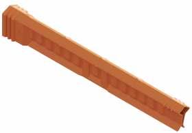


135 COVER-UP AND INSULATING RUBBER RITZ FERRAMENTAS C COVER SET
PIN INSULATOR Catalog Reference Application Description Approx. Weight kg lb COB08835-2 Conductor For rubber glove work For conductors up to Ø 25 mm. Approx. length 1.460 mm 2.50 5.51 RM4948 Disc insulator With metallic bracket for hot stick 2.95 6.50 Rated voltage 36.6 kV (phase/phase)
SET
Catalog Reference Application Description Approx. Weight kg lb RM4931 Conductor For hot stick work For conductors up to Ø 45 mm. Approx. length 1.525 mm 4.20 9.26 RC406-0046 Pin insulator With metallic bracket for hot stick work 3.90 8.60 Rated voltage 48.3 kV (phase/phase)
CONDUCTOR /
COVER
CONDUCTOR / PIN INSULATOR
Catalog Reference Application Description Approx. Weight kg lb RC406-0514GA Conductor For hot-stick work For conductors up to Ø 25 mm Approx. length 1.530 mm 2.15 4.74 RC406-0557 Pin Insulator 305 mm Height with metallic bracket for hot stick 1.10 2.43 RC406-0557L Pin Insulator 419 mm Height with metallic bracket for hot stick 1.40 3.09 Rated voltage 36.6 kV (phase/phase
RM4948
COB08835-2
RM4931
RC406-0046 RC406-0514GA RC406-0557L

SPIRAL COVER FOR CONDUCTOR
| Rated voltage 72.5 kV (phase/phase)
| COB31387-1
Protection against accidental contact for electricians during maintenance procedures on energized networks.
Manufactured with thermoplastic of high dielectric rigidity, ensuring resistance and durability. Its orange color not only makes it easily visible but also makes it resistant to damage caused by UV rays.
For greater convenience and safety during installation, the cover is equipped with a metal clamp that allows fixation using the distance method, using a operating rod
Approx. length 1,000 mm
Approx. Weight: 3.87 kg (8.51 lb)

SECONDARY CONDUCTOR COVER (LV)
| Rated voltage 14.6 kV (phase/phase)
| COB03333-1
It was designed for temporary mounting in secondary networks up to Ø 25 mm, in order to avoid accidental human or tool contacts with low voltage conductors during maintenance around the pole or even in medium voltage work.
One of its great advantages is that it is lightweight and can be coupled with other units of the same type through its male-female system, to insulate long extensions.
This cover has no metallic brackets, so it must be mounted in the network with the rubber glove method.
Approx. length 1.320 mm
Approx. Weight: 0.45 kg (0.99 lb)
136 RITZ FERRAMENTAS COVER-UP AND INSULATING RUBBER C
COB31387-1
COMPACT SYSTEM COVERS
| Rated voltage 36.6 kV (phase/phase)
| COB11147-1
For spacer cable system conductors up to Ø 25 mm.
Approx. length 880 mm
Approx. Weight: 0.90 kg (1.98 lb)
| Rated voltage 26.4 kV (phase/phase)
| COB11047-1
Protective cover for horizontal support when changing pin insulators. Composed of two parts, which are installed overlap, providing full protection of the supports.
Approx. Weight: 1.25 kg (2.76 lb)
| COB11170-1
Protective cover for protection of the supports when changing pin insulators. Applied in type “C” support. Each model is composed of two parts, which are overlaid, providing full protection of the supports.
Approx. Weight: 1.10 kg (2.43 lb)
| COB11170-2
Protective cover for protection of the supports when changing post insulators. Applied in type “C” support. Each model is composed of two parts, which are overlaid, providing full protection of the supports.
Approx. Weight: 1.25 kg (2.76 lb)
| COB11050-1
Protective cover for lozenge-shaped spacers, its main function to protect the conductor near the lozenge-shaped spacers.
Approx. Weight: 0.70 kg (1.54 lb)
| COB11051-1
Protective cover for pin insulator. It has clip and rope for fixing the set thus avoiding its accidental displacement.
Approx. Weight: 0.80 kg (1.76 lb)
TRANSFORMER BUSHING COVER
| Rated voltage 26.4 kV (phase/phase)
| COB30064-1
It is designed for insulating protection of the transformer bushing assembly and temporary jumper for transformer bushings. A protective cover made of rigid polyethylene with high dielectric strength, resistant to ozone and UV.
Approx. Weight: 0.78 kg (1.70 lb)


137 COVER-UP AND INSULATING RUBBER RITZ FERRAMENTAS C
COB11170-1
COB11170-2
COB11050-1
COB11051-1
COB11147-1
Square-on-point
COB30064-1
COB11047-1

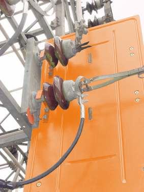


INSULATING COVERS FOR MAINTENANCE WORKS ON ENERGIZED SUBSTATIONS
The insulating cover set consists of:
- Side Guard;
- Cover for fixed contact of the disconnect switch;
- Straight cover for buses;
- Adapter and mounting head protect adjacent circuits, fixed disconnect contacts and buses, providing a safe working condition and preventing accidental contacts with energized parts.
The versatility of this set offers protection for disconnect switches of: 630 A and 1250 A - one-pole and 1250 A - three-pole, and others.
Quick mounting and unmounting with conventional hot stick.
Side Guard
Mounted on adjacent bays closest to the gantry to be insulated, providing full protection to the operator and the work area. Mounted to the structure by removable fiberglass hooks, for different installation positions.
138 RITZ FERRAMENTAS COVER-UP AND INSULATING RUBBER C
Catalog Reference Description Dimensions (mm) Approx. Weight A B kg lb COB11612-1 Substation Side Guard with vertical Installation 1430 730 7,05 15,54 COB22404-1 Substation Side Guard with vertical Installation 1800 740 9,45 20,83 COB26095-1 Substation Side Guard with horizontal Installation 1800 740 9,45 20,83 Rated voltage 26.4 kV (phase/phase) A B
COB11612-1
Horizontal installation
Vertical installation
Cover for Disconnect Switch Fixed Contact
It is designed to insulate the fixed contact of the disconnect switch Ø 250 mm. It has removable and adjustable mounting hooks for different types of switches, as well as different truss dimensions.

Straight Cover for Buses
Similar to the conductor cover for hot line work. It offers a wide protection range when insulating energized buses up to Ø 58 mm near the work area.

| RM4455-84
Universal Adapter
It is provided with a thumbscrew to couple to a universal head, allowing the change of the installation angle of a tool
Approx. Weight: 0.11 kg (0.24 lb)
| FLV11623-1
Installation Head
An aluminum mounting head, with fiberglass poles, is used with universal adapter for mounting and removal of covers and insulating guards.
Approx. Weight: 0.15 kg (0.33 lb)


139 COVER-UP AND INSULATING RUBBER RITZ FERRAMENTAS C
Catalog Reference Rated Voltage (phase/phase) Dimensions (mm) Approx. Weight Length Height kg lb COB11617-1 14.6 kV 620 500 2.65 5.84 COB20663-1 26.4 kV 660 660 5.98 13.18
Catalog Reference Rated Voltage (phase/phase) Dimensions (mm) Approx. Weight Length Height kg lb COB11622-1 14.6 kV 750 200 0.70 1.54 COB20664-1 26.4 kV 750 250 1.30 2.87
FLV11623-1
RM4455-84
COB11622-1
COB11617-1


PERMANENT COVERS
They are made in rigid black thermoplastic and are resistant to ultraviolet rays and electrical tracking and are suitable for hot-stick and rubber glove hot line use.
Cover for Structure-Mounted Disconnect Base
| Rated voltage 14.6 kV (phase/ground)
| COB19874-1
It is designed for protection between the disconnect switch housing and energized parts. Permanent use avoids short circuit caused mainly by the contact of birds and other animals.
Approx. Weight: 4.80 kg (10.60 lb)
Shunt Connector Cover
| Rated voltage 14.6 kV (phase/phase)
| COB13559-1
For wedge tap connectors on protected distribution lines. Rubber glove work only.
Approx. Weight: 0.10 kg (0.22 lb)
Covers for Stirrup Connector
For protected distribution line stirrup connectors and clamps
| Rated voltage 25 kV (phase/phase)


140 RITZ FERRAMENTAS COVER-UP AND INSULATING RUBBER C
COB13559-1
COB19874-1
Weight: 0.95 kg (2.09 lb)
| COB14959-1 Approx.
Weight: 0.58 kg (1.28 lb) 330 335 330 220
| COB31716-1
Approx.
Transformer Bushing Covers
The bushing cover are used for protection of the transformer terminals on distribution systems, preventing short-circuiting, mainly related to birds and other small animals.
| Rated voltage 14.6 kV (phase/phase)

It can be easily installed with specific plastic fasteners, available in one single model for several brands and models of transformers.
Approx. Weight: 0.13 kg (0.29 lb)
It has a staggered perpendicular output for distribution cables up to Ø 21mm, simple installation by predisposed pins.
Approx. Weight: 0.17 kg (0.37 lb)
For cables Ø 25 mm and Ø 15 mm. simple installation by predisposed pins.
Approx. Weight: 0.13 kg (0.29 lb)

It can be installed on several sizes of cables
Approx. Weight: 0.11 kg (0.24 lb)

It has a staggered perpendicular output for distribution cables up to Ø 18mm, simple installation by predisposed pins.
Approx. Weight: 0.10 0.22 kg ( lb)

141 COVER-UP AND INSULATING RUBBER RITZ FERRAMENTAS C
| COB24863-1
| COB24885-1
| COB24891-1
| COB11721-1
| COB18644-1
Rated voltage 1 kV (phase/phase) 50 50 44 176 Ø 51 55 70 62 247 Ø 56
Rated voltage 25 kV (phase/phase) 20° 78 137 146 199 29 19 Ø 73
|
131 160 52° Ø 115 211 Ø 87 Ø 108 Ø 28 Ø 24 Ø 17


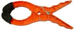

INSULATED RUBBER BLANKET
Intended for the protection of electricians against accidents by contact at energized points of the structure during maintenance in electrical networks Due to its flexibility, it allows the covering of irregularly shaped parts such as disconnecting switch, secondary racks, pin insulators, anchor chains, crossings, etc.
Made from special ozone and corona resistant rubber material, orange color, type II (resistant to ozone effects).
| Nominal work voltage (phase/phase): 36kV (Class 4 / Type II / Construction Style A)
The Slotted Type has eyelets along its borders, allowing special applications in quite diverse situations through fixing by p lastic button.
| LIR-BLR
Plastic button to fix rubber blankets.
Cover Pegs
Used to secure and position rubber blanket and covers, aiming to protect the electrician during live-line activities. Available in models for installation by contact and by remote method
Maximum opening: 90 mm
Length: 205 mm
| FLV04417-1
Manual plastic peg for rubber glove work
Peso aprox.: 0.10 kg (0.22 lb)
| FLV04417-2
Plastic peg with ring for hot stick work.
Approx. Weight: 0.14 kg (0.33 lb)
Maximum opening: 100 mm
Length: 240 mm
| FLV16886-1
Manual plastic peg for rubber glove work, with rubber protective cover at the tip.
Approx. Weight: 0.12 kg (0.26 lb)
| FLV16886-2
Plastic peg with ring for hot stick work, with rubber protective cover at the tip
Approx. Weight: 0.16 kg (0.35 lb)
142 RITZ FERRAMENTAS COVER-UP AND INSULATING RUBBER C
Catalog Reference Description Approx. Dimensions (mm) Approx. Thickness (mm) Approx. Weight kg lb LR-4/II Solid 900 x 900 4.00 4.40 9.70 LR-SP-4/II Slotted 900 x 900 4.50 9.92 LR-SP-4/II-30396 Slotted 1000 x 1400 4.50 9.92 LR-TP-4/II Three slot 900 x 1100 5.70 12.60
LR-SP-4/II LR-4/II
LR-TP-4/II
LIR-BLR
II-30396
LR-SP-4
FLV16886-1
FLV16886-2
FLV04417
Detail without rubber protection
FLEXIBLE COVER FOR CONDUCTORS
Cover for conductors manufactured in orange insulating flexible rubber and in accordance with ASTM D1050 standard requirements. Used as a portable safety device designed to cover exposed energized power lines and to protect electricians from accidental touching and closing circuits during distribution network maintenance.
This cover line has ozone and ultraviolet rays exposure-resistant material (TYPE II), developed for several voltage classes, conductor diameters and lengths
The cover assembly enjoys the rubber's natural tendency of grabbing and squeezing through compression. The angled end grooves facilitate sliding between covers for installation, but prevent separation during operation. In order to disengage, the operator should only squeeze the rubber on each side.
STYLE A (without nozzle)
Has grooves on its ends for placing and securing nozzles from Style B covers, which aid and ensure the required adherence to prevent sliding during interventions
STYLE B (with nozzle)
Has grooves on one of its ends and a nozzle on the other for placing and securing, which aid and ensure the required adherence to prevent sliding during interventions.


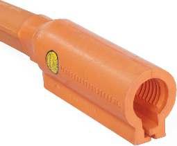
143 COVER-UP AND INSULATING RUBBER RITZ FERRAMENTAS C
FLEXIBLE COVER FOR CONDUCTORS - Type II – Style A (without nozzle)
144 RITZ FERRAMENTAS COVER-UP AND INSULATING RUBBER C
Cat. No. Type Nominal Voltage Class Tension Test Applied Style Ø (in) Length (ft) Approx. Weight (lb) FLX30500-1 II 2 (17 kV) 20 kV A 1" 3 2.27 FLX30500-2 II 2 (17 kV) 20 kV A 1" 3.5 2.65 FLX30500-3 II 2 (17 kV) 20 kV A 1" 4.5 3.40 FLX30500-4 II 2 (17 kV) 20 kV A 1" 5 3.79 FLX30500-5 II 2 (17 kV) 20 kV A 1" 6 4.54 FLX30500-6 II 2 (17 kV) 20 kV A 1" 6.5 4.92 FLX30502-1 II 2 (17 kV) 20 kV A 1.25" 3 2.89 FLX30502-2 II 2 (17 kV) 20 kV A 1.25" 3.5 4,28 FLX30504-1 II 3 (26.5 kV) 30 kV A 1.5" 3 3.24 FLX30504-2 II 3 (26.5 kV) 30 kV A 1.5" 3.5 4.87 FLX30504-3 II 3 (26.5 kV) 30 kV A 1.5" 5 5.42 FLX30504-4 II 3 (26.5 kV) 30 kV A 1.5" 6 6.50 FLX30504-5 II 3 (26.5 kV) 30 kV A 1.5" 6.2 6.72
Cat. No. Type Nominal Voltage Class Tension Test Applied Style Ø (in) Length (ft) Approx. Weight (lb) FLX30501-1 II 2 (17 kV) 20 kV B 1" 3 2.93 FLX30501-2 II 2 (17 kV) 20 kV B 1" 3.5 3.33 FLX30501-3 II 2 (17 kV) 20 kV B 1" 4.5 4.79 FLX30501-4 II 2 (17 kV) 20 kV B 1" 5 4.45 FLX30501-5 II 2 (17 kV) 20 kV B 1" 6 5.23 FLX30501-6 II 2 (17 kV) 20 kV B 1" 6.5 5.60 FLX30505-1 II 3 (26.5 kV) 30 kV B 1,5" 3 4.37 FLX30505-2 II 3 (26.5 kV) 30 kV B 1,5" 4.5 6.0 FLX30505-3 II 3 (26.5 kV) 30 kV B 1,5" 5 6.55 FLX30505-4 II 3 (26.5 kV) 30 kV B 1,5" 6 7.63 FLX30505-5 II 3 (26.5 kV) 30 kV B 1,5" 6.5 7.85
FLEXIBLE COVER FOR CONDUCTORS - Type II – Style B (with nozzle)
RUBBER INSULATING GLOVES AND SLEEVES
Rubber Insulating Glove
Insulating glove made of natural and synthetic rubber which brings better flexibility in the glove. Type II glove, resistant to ozone and halogenated, thus avoiding the use of talc in its use.
The gloveis designedto protect the electrician's hand, wrist,and forearm against electrical discharges, allowing free movement of the fingers.
RUBBER INSULATING GLOVE


145 COVER-UP AND INSULATING RUBBER RITZ FERRAMENTAS C
Catalog Reference Size Length Class Voltage Class (kV) Adhesive Color Approval Certificate Pol mm Pol mm RTZ-14-00-8 8 203 14 356 00 0.5 Beige 2.178 RTZ-14-00-8,5 8.5 216 RTZ-14-00-9 9 229 RTZ-14-00-9,5 9.5 241 RTZ-14-00-10 10 254 RTZ-14-00-10,5 10.5 267 RTZ-14-00-11 11 279 RTZ-14-00-11,5 11.5 292 RTZ-14-00-12 12 303 RTZ-14-0-8 8 203 14 356 0 1 Red 29.775 RTZ-14-0-8,5 8.5 216 RTZ-14-0-9 9 229 RTZ-14-0-9,5 9.5 241 RTZ-14-0-10 10 254 RTZ-14-0-10,5 10.5 267 RTZ-14-0-11 11 279 RTZ-14-0-11,5 11.5 292 RTZ-14-0-12 12 303 RTZ-14-1-8 8 203 14 356 1 7.5 White 29.774 RTZ-14-1-8,5 8.5 216 RTZ-14-1-9 9 229 RTZ-14-1-9,5 9.5 241 RTZ-14-1-10 10 254 RTZ-14-1-10,5 10.5 267 RTZ-14-1-11 11 279 RTZ-14-1-11,5 11.5 292 RTZ-14-1-12 12 303
RUBBER INSULATING GLOVE
146 RITZ FERRAMENTAS COVER-UP AND INSULATING RUBBER C
Catalog Reference Size Length Class Voltage Class (kV) Adhesive Color Approval Certificate Pol. mm Pol. mm RTZ-14-2-8 8 203 14 356 2 17 Yellow 29.773 RTZ-14-2-8,5 8.5 216 RTZ-14-2-9 9 229 RTZ-14-2-9,5 9.5 241 RTZ-14-2-10 10 254 RTZ-14-2-10,5 10.5 267 RTZ-14-2-11 11 279 RTZ-14-2-11,5 11.5 292 RTZ-14-2-12 12 303 RTZ-16-3-8 8 203 16 406 3 26,5 Green 29.772 RTZ-16-3-8,5 8.5 216 RTZ-16-3-9 9 229 RTZ-16-3-9,5 9.5 241 RTZ-16-3-10 10 254 RTZ-16-3-10,5 10.5 267 RTZ-16-3-11 11 279 RTZ-16-3-11,5 11.5 292 RTZ-16-3-12 12 303 RTZ-16-4-8 8 203 16 406 4 36 Orange 29.771 RTZ-16-4-8,5 8.5 216 RTZ-16-4-9 9 229 RTZ-16-4-9,5 9.5 241 RTZ-16-4-10 10 254 RTZ-16-4-10,5 10.5 267 RTZ-16-4-11 11 279 RTZ-16-4-11,5 11.5 292 RTZ-16-4-12 12 303
Rubber Insulating Sleeve
Rubber insulating sleeves are specially produced as electrical insulators for workers in the electrical sector, aiming to protect the arms and forearms
The sleeves are made of high quality elastomeric compound and mee ASTM D1051/NBR 10623 Standard They have straps and buttons and are sold in medium and large sizes. Available in black and orange colors.

147 COVER-UP AND INSULATING RUBBER RITZ FERRAMENTAS C
Catalog Reference Size Class Tension Class kV Adhesive Color Approval Certificate RTZ-PR-0-M Medium 0 1 Black 29.588 RTZ-LA-0-M Medium 0 1 Orange 37.748 RTZ-PR-1-M Medium 1 7.5 Black 29.578 RTZ-LA-1-M Medium 1 7.5 Orange 37.754 RTZ-PR-2-M Medium 2 17 Black 1.505 RTZ-LA-2-M Medium 2 17 Orange 25.589 RTZ-PR-2-G Large 2 17 Black 1.505 RTZ-LA-2-G Large 2 17 Orange 25.589 RTZ-PR-3-M Medium 3 26.5 Black 25.589 RTZ-LA-3-M Medium 3 26.5 Orange 29.573 RTZ-PR-3-G Large 3 26.5 Black 29.589 RTZ-LA-3-G Large 3 26.5 Orange 29.573 RTZ-PR-4-M Medium 4 36 Black 33.400 RTZ-LA-4-M Medium 4 36 Orange 35.724 RTZ-PR-4-G Large 4 36 Black 33.400 RTZ-LA-4-G Large 4 36 Orange 35.724
RUBBER INSULATING SLEEVE


REMOVABLE PROTECTIVE COVER
Designed to protect energized circuits up to 38 kV phase/phase, avoiding phase-to-phase or phase-to-ground contact, which can be accidentally caused by animals, generating possible shutdowns.
They are made of flexible plastic and specially molded on demand for the most different types and application conditions, such as: connector, splice, bus, and bushing in medium voltage structures. It can be quickly installed on these components and fastened with nylon clips.
These covers are fully reusable and can be removed and reinstalled for inspections in structural components.


148 RITZ FERRAMENTAS COVER-UP AND INSULATING RUBBER C

Repair Sets and Lubricants. . . . . . . . . . . . . . . . . 151 Storage . . . . . . . . . . . . . . . . . . . . . . . . . . . . . . . . . . . 153 Tool Trailer . . . . . . . . . . . . . . . . . . . . . . . . . . . . . . . . 158 TOOL REPAIR AND STORAGE GROUP D Access our site.
TOOL REPAIR AND STORAGE GROUP D
REPAIR SETS AND LUBRICANTS
Before purchasing these restorers and lubricants, we recommend that you obtain from our sales department basic information on their applications and export policy for chemical products.
These products can be easily applied by the user.
| RT400-0803
Gloss Restorer
Is a colorless resin specially prepared for surface restorations in RITZGLAS® poles when they present surface wear and loss of gloss.
These types of damage on insulated poles compromise their dielectric strength, caused by moisture and impurity contamination.
Supplied with ten 100 ml bottles, being five units of component A and five of component B, packed in a plastic case
Approx. Weight: 2.60 kg (5.37 lb)

RT400-0803
151 TOOL REPAIR AND STORAGE RITZ FERRAMENTAS D


| RM1909
Tool Lubricant
Made of non-toxic and non-corrosive materials. It has high lubricating power, preventing oxidation through a durable film, avoiding friction and wear of metal tools.
Approx. Weight: 2.10 kg (4.63 lb)
| RH1917
Bond Patching
Set is an orange resin and hardener set recommended only for recovering from minor cracks or other surface damage such as tears or splits caused by accidental or improper use of the equipment, and to reposition metal heads in poles.
Supplied in two 100 ml bottles, components A and B
Approx. Weight: 0.32 kg (0.71 lb)
| RM1904
Silicone-soaked hot stick wiping cloth for surface treatment
Cloth measuring 500 x 500 mm. Soaked with silicone and designed for surface applications on the pole for preventive protection, leaving a protective layer in its surface.
Approx. Weight: 0.08 kg (0.18 lb)
152 TOOL REPAIR AND STORAGE RITZ FERRAMENTAS D
RH1917
RM1904
RM1909
STORAGE
Bucket Tote Bag
Tote bag made of durable and waterproof canvas with bottom reinforced by thermoplastic material. Strap of polypropylene rope, fixed at its edge through metal eyelets, which accompanies carabiner to enable its removal. Excellent stitching and finishing
| FLV16364-1
The bag is used for transportation and storage of ropes used in hot line interventions, to avoid contamination and easy handling.
Ø 300 mm x 400 mm deep
Approx. Weight: 1,90 kg (4,19 lb)
Useful in packaging, transport and especially in the hoisting of hot line tools in the work structure, providing protec tion and safety in moving them.
| RC417-0144
Ø 305 mm x 380 mm deep
Approx. Weight: 0,49 kg (1,10 lb)
| RC417-0146
Ø 180 mm x 255 mm deep
Approx. Weight: 0,27 kg (0,60 lb)


153 TOOL REPAIR AND STORAGE RITZ FERRAMENTAS D
FLV16364-1
RC417-0144


Transportation Bags
Due to their small weight, waterproof bags become practical and safe when transporting the grounding sets. Reinforced material, with fiberglass bottom, suitable for cable and hardware storage.
| ATR09962-1
Dimensions: 290 mm (A) x 240 mm (L) x 645 mm (C)
Volume: 0.04 m³
| ATR14484-1
Dimensions:330 mm (A) x 240 mm (L) x 300 mm (C)
Volume: 0.02 m³
| ATR14484-2
Dimensions: 420 mm (A) x 270 mm (L) x 400 mm (C)
Volume: 0.04 m³
| Bag Type
Made of reinforced material, suitable for cables and fittings

154 TOOL REPAIR AND STORAGE RITZ FERRAMENTAS D
Catalog Reference Dimensions (mm) Volume (m³) A L C ATR16843-1* 250 340 1350 0.11 ATR16843-2* 250 340 1550 0.13 ATR16843-3* 180 210 1550 0.06 ATR16843-4* 280 240 1100 0.07 ATR16843-5 200 240 900 0.04 ATR16843-6 150 200 800 0.03 ATR16843-7 150 200 550 0.02
* They have an internal division to storege the grounding rod
ATR16843
ATR14484-2
ATR09962-1
Bag for Telescopic Hot Sticks (VTT)
Useful in packing and transporting the telescopic hot sticks, according to their appropriate size, providing protection and safety of tools.
Made of water-resistant green canvas. Reinforced synthetic leather strap with double layer. Has a pocket for carrying the heads. Excellent stitching and finishing.
155 TOOL REPAIR AND STORAGE RITZ FERRAMENTAS D
Catalog Reference Dimensions (m) A B SLT-2/3 1.55 0.12 SLT-4/5 1.66 0.14 SLT-6/7 1.75 0.16 SLT-8/9 1.86 0.18 VTT17182-5 1.97 0.20 VTT17182-6 2.08 0.22 VTT17182-7 2.19 0.22 135 120 A B
Bag for Sectional Hot Sticks (VMR)
Has reinforced edges. internal dividers for the proper storage of hot stick sections, a carrying handle, and an additional pocket for a tool head.
156 TOOL REPAIR AND STORAGE RITZ FERRAMENTAS D Catalog Reference Rod Internal Dividers Dimensions (m) Rod VMR Lenght Width (A) VMR10484-1 ATR00137-1 1 3 1.51 0.38 VMR10484-2 ATR00137-2 1 3 1.51 0.38 VMR10484-3 - - 3 1.51 0.26 VMR16824-1 - - 1 1.51 0.11 VMR16824-2 - - 2 1.51 0.19 VMR16825-1 - - 4 1.51 0.34 VMR16825-2 ATR00137-2 1 4 1.51 0.42 VMR16826-1 - - 5 1.51 0.42
120 130 1510 A
Bag for Sticks
Useful in packing and transporting various types of sticks, according to their appropriate size, providing protection and safety of tools.
Made of water-resistant green canvas. Reinforced synthetic leather strap with double layer. Excellent stitching and finishing.
157 TOOL REPAIR AND STORAGE RITZ FERRAMENTAS D
Catalog Reference Dimensions (m) A B FLV18339-1 1.49 0.17 FLV18339-2 2.10 0.17 FLV18339-3 2.71 0.17 FLV18339-4 3.32 0.17 FLV18339-5 4.00 0.17 FLV18339-6 1.20 0.34 FLV18339-7 1.50 0.34 FLV18339-8 1.75 0.34 FLV18339-9 2.10 0.34 FLV18339-10 2.40 0.34 FLV18339-11 2.70 0.34 FLV18339-12 1.70 0.17 FLV18339-13 2.40 0.17 FLV18339-14 4.60 0.17 FLV18339-15 1.00 0.17 FLV18339-16 5.10 0.17 FLV18339-17 6.10 0.17 150 A B


TOOL TRAILER

| FLV03102-1
Hot line tool storage and transport trailer
Rated Work Capacity: 1500 kg (3306 lb)
Approx. Weight: 1420 kg (3130 lb)
TECHNICAL CHARACTERISTICS
- Chassis structure in steel profiles;
- Wheel set: 16'' rim (215 x 80 x16 tires);
- Suspension type; Leaf spring assembly and telescopic shock absorbers;
- Tandem axle suspension and lubricated balance system;
- Rear cover lifting system; Pantograph type, crank screw drive;
- 4 ton overrun brake assembly;
- Jockey wheel suspension for 120 kg (265 lb);
- Supplied with wheel wrench and spare wheel;
- Ball-and-shell trailer coupling;
- Electrical supply between tow truck and trailer; electric harness with a 7-pole 12V outlet;
- Internal heating system; Bi-volt cooler with selector switch (110 or 220 Volts); Cooler is powered by a harness (when parked)
- Rubber lined ladder holders mounted on the rear cover.
NOTE
Adapt the trailer to a vehicle with a towing capacity of at least 3 ton.
158 TOOL REPAIR AND STORAGE RITZ FERRAMENTAS D
Jockey wheel
Climatizer Electric
Power plug 600 565 2368 4385 1200 415 590 1745 590 282 282 505 505 4430
Tool storage rack
whip

“U”- Shape Side-rails. . . . . . . . . . . . . . . . . . . . . . . 161 Oblong-Shape Side-rails. . . . . . . . . . . . . . . . . . . 164 “A” Shape Ladders . . . . . . . . . . . . . . . . . . . . . . . . . 165 Mobile Tower Type Ladder. . . . . . . . . . . . . . . . . 166 Hot Line Ladder 167 Accessories for Ladder Support . . . . . . . . . . . . 171 Adjustable Ladder Hooks . . . . . . . . . . . . . . . . . . 173 Ladder with Double siderail . . . . . . . . . . . . . . . 174 Insulating Spacer for Ladders . . . . . . . . . . . . . . 175 Platform . . . . . . . . . . . . . . . . . . . . . . . . . . . . . . . . . . 176 Insulating Stool . . . . . . . . . . . . . . . . . . . . . . . . . . . 178 Insulating Modular Scaffold . . . . . . . . . . . . . . . 179 Insulating Scaffold Equalization and Grounding Kit . . . . . . . . . . . . . . . . . . . . . . . . . . . . 188 LADDERS, PLATFORMS AND INSULATING SCAFFOLD GROUP E Access our site.
LADDERS, PLATFORMS AND INSULATING SCAFFOLD GROUP E
Ritz ladders are extremely sturdy and durable They can be used indefinitely (as long as the care and conservation procedures in the manual are observed) and are portable, allowing manual transport.
Their type and size are suitable for the tasks at hand and are in good use and conservation conditions for safe and highly productive work.
“U”- SHAPE SIDE-RAILS
Single and extension ladder with U-shape fiberglass side-rails, round aluminum rungs, non-slip grooves with nylon strap and rubber shoe, meeting category IA of ANSI A14.5.
Resistant to weather and ultraviolet, it has safety strips in yellow and black
These ladders are intended for maintenance in de-energized structures or up to 15 kV by the distance work method (using insulating poles).
Nominal Working Capacity: 136 daN (300 lb)
LADDERS, PLATFORMS AND INSULATING SCAFFOLD

161
RITZ FERRAMENTAS E
“U”- shape
SINGLE LADDER

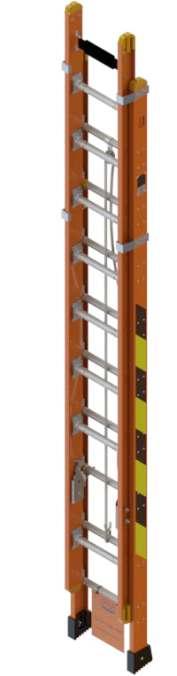
EXTENSION LADDER
162 LADDERS, PLATFORMS AND INSULATING SCAFFOLD RITZ FERRAMENTAS E
Catalog Reference Nominal Length (m) Qty. of Rungs Approx. Weight kg lb ES/PU-29-CN-SB 3.09 9 9.20 20.28 ES/PU-32-CN-SB 3.39 10 10.10 22.27 ES/PU-35-CN-SB 3.69 11 11.00 24.25 ES/PU-38-CN-SB 4.00 12 11.90 26.24 ES/PU-41-CN-SB 4.29 13 12.80 28.22 ES/PU-44-CN-SB 4.59 14 13.70 30.20 ES/PU-47-CN-SB 4.89 15 14.60 32.19 ES/PU-50-CN-SB 5.20 16 15.50 34.17 ES/PU-53-CN-SB 5.49 17 16.40 36.16 ES/PU-56-CN-SB 5.80 18 17.30 38.14 ES/PU-59-CN-SB 6.10 19 18.20 40.12 ES/PU-62-CN-SB 6.40 20 19.10 42.11 ES/PU-65-CN-SB 6.69 21 20.00 44.09 Inner width between siderails: 320 mm Distance between rungs: 300 mm
Catalog Reference Nominal Length (m) Qty. of Rungs Approx. Weight Retracted Extended kg lb EE/PU-35-CN-SB 2.68 3.67 11 16.00 35.27 EE/PU-41-CN-SB 2.96 4.27 13 17.70 39.02 EE/PU-47-CN-SB 3.28 4.87 15 18.50 40.79 EE/PU-53-CN-SB 3.68 5.47 17 21.20 46.74 EE/PU-59-CN-SB 3.99 6.08 19 23.00 50.71 EE/PU-65-CN-SB 4.28 6.68 21 24.80 54.67 EE/PU-71-CN-SB 4.58 7.27 23 26.50 58.42 EE/PU-77-CN-SB 4.87 7.87 25 28.30 62.39 EE/PU-84-CN-SB 5.17 8.46 27 30.00 66.14 EE/PU-90-CN-SB 5.40 9.07 29 31.70 69.89 EE/PU-97-CN-SB 6.09 9.97 33 34.00 74.96
300 mm
Width between side rails: Top Section - 293 mm Bottom Section - 320 mm Distance between rungs:
EXTENSION LADDER - “D” profile rungs


163
INSULATING SCAFFOLD RITZ FERRAMENTAS E
LADDERS, PLATFORMS AND
Catalog Reference Nominal Length (m) Qty. of Rungs Approx. Weight Retracted Extended kg lb EE/PUD-35-CN-SB 2.68 3.67 11 16.00 35.27 EE/PUD-41-CN-SB 2.96 4.27 13 17.70 39.02 EE/PUD-47-CN-SB 3.28 4.87 15 18.50 40.79 EE/PUD-53-CN-SB 3.68 5.47 17 21.20 46.74 EE/PUD-59-CN-SB 3.99 6.08 19 23.00 50.71 EE/PUD-65-CN-SB 4.28 6.68 21 24.80 54.67 EE/PUD-71-CN-SB 4.58 7.27 23 26.50 58.42 EE/PUD-77-CN-SB 4.87 7.87 25 28.30 62.39 EE/PUD-84-CN-SB 5.17 8.46 27 30.00 66.14 EE/PUD-90-CN-SB 5.40 9.07 29 31.70 69.89 EE/PUD-97-CN-SB 6.09 9.97 33 34.00 74.96 Width between side rails: Top Section - 305 mm Bottom Section - 335 mm Distance between rungs: 300 mm
Oblong-shape


OBLONG-SHAPE SIDE-RAILS
Single and extension ladders, with side-rails (oblong shape) and rungs (round, non-slip), made of RITZGLAS® tubes. They are finished in polyurethane painting and equipped with a rubber-coated nylon support band, movable or fixed shoes with non-slip rubber, meeting category IA of ANSI A14.5.
Extendable models feature nylon pulleys (for smooth sliding of its parts), metal rings on base rungs, steel ratchets and plastic-coated side guides.
These ladders are intended for maintenance in de-energized structures, or up to 15 kV, using the distance work method (using insulated poles).
For maintenance up to 15 kV (using the contact method) we recommend the Double Stringer Ladders with Insulated Ladder Spacer FLV14717-1 (see specific page).
Nominal Working Capacity: 136 daN (300 lb)
SINGLE LADDER
EXTENSION LADDER
* It must be supported when used through eyebolts on the last rung of the fixed part (base).
Width between side rails: Top Section - 365 mm
Bottom Section - 305 mm
Distance between rungs: 305 mm
164 LADDERS, PLATFORMS AND INSULATING SCAFFOLD RITZ FERRAMENTAS E
Catalog Reference Nominal Length (m) Qty. of Rungs Approx. Weight kg lb ES/PR-8/27-CN-SM 2.78 8 11.00 24.25 ES/PR-8/40-CN-SM 4.03 12 15.52 34.21 ES/PR-8/46-CN-SM 4.65 14 17.78 39.20 ES/PR-8/58-CN-SM 5.84 18 22.30 49.16 Inner width between siderails: 305 mm Distance between rungs: 305 mm
Catalog Reference Nominal Length (m) Qty. of Rungs Approx. Weight Retracted Extended kg lb EE/PR-12/58-CN-SM 3.45 5.86 19 30.00 66.13 EE/PR-12/70-CN-SM 4.05 7.08 23 35.50 78.26 EE/PR-12/82-CN-SM 4.64 8.28 27 39.00 86.00 EE/PR-15/95-CN-SM 5.25 9.52 31 50.00 110.23 EE/PR-15/10-CN-SM 6.28 10.76 35 54.00 119.00 EE/PR-15/11-CN-SM 6.88 11.98 39 61.00 134.48 EE/PR-15/14-CN-SM * 7.80 13.84 45 67.00 147.71
“A” SHAPE LADDERS
Designed for maintenance on de-energized structures. It consists of hinged segments at the upper end, with opening limiter. It has a top board for tools and other objects
Nominal Working Capacity: 136 daN (300 lb)
For step ladders (heavy category) supplied with Ø 3/8” fiberglass rods at the center of its rungs, the “/TR” suffix must be added to its reference code.
Example: EA/PR-21/PD/TR
Double
With rungs on both sides.

165 LADDERS, PLATFORMS AND INSULATING SCAFFOLD RITZ FERRAMENTAS E
Reference Rated Length (m) Qty. of Rungs on each side Approx. Weight A B C D kg lb EA/PR-12/PD 1.22 0.55 0.93 0.42 x 0.25 03 15.10 32.29 EA/PR-15/PD 1.51 0.58 1.16 0.42 x 0.25 04 18.60 41.00 EA/PR-21/PD 2.13 0.62 1.30 0.42 x 0.25 06 25.50 56.22 EA/PR-27/PD 2.73 0.71 1.80 0.42 x 0.25 08 32.70 72.09 EA/PR-34/PD 3.35 0.78 2.12 0.42 x 0.25 10 40.30 88.84 EA/PR-40/PD 3.96 0.85 2.37 0.42 x 0.25 12 48.00 105.82 EA/PR-52/PD 5.17 0.97 3.07 0.42 x 0.25 16 64.30 141.76 Distance between rungs 305 mm B A C D D
Catalog

MOBILE TOWER TYPE LADDER
It provides a condition of access and positioning of the electrician at necessary heights for carrying out the most diverse types of maintenance work in electrical systems (substations and industries).
Made of RITZGLAS®, with a 600 mm x 600 mm platform and a 200 mm high baseboard Distance between steps of 210 mm with non-slip tape It has 6" casters and polyurethane paint finish to ensure external use Its binding elements are manufactured in thermally treated cast aluminum alloy that allow disassembly for displacement and storage.
Nominal Working Capacity: 136 daN (300 lb)
166 LADDERS, PLATFORMS AND INSULATING SCAFFOLD RITZ FERRAMENTAS E
Catalog Reference Nominal Length (mm) Qty of Rungs Approx. Weight A B C kg lb ETM/01 420 1680 832 01 29.10 64.15 ETM/02 630 1890 953 02 33.00 72.75 ETM/03 840 2100 1074 03 36.80 81.10 ETM/04 1050 2310 1195 04 40.70 89.70 ETM/05 1260 2520 1316 05 44.60 98.30 ETM/06 1470 2730 1437 06 48.50 106.90 ETM/07 1680 2940 1558 07 52.40 115.50 ETM/08 1890 3150 1679 08 56.20 123.90 ETM/09 2100 3360 1800 09 60.10 132.50 ETM/10 2310 3570 1921 10 64.00 141.10 ETM/11 2520 3780 2042 11 67.80 149.50 ETM/12 2730 3990 2163 12 71.70 158.10 ETM/13 2940 4200 2284 13 75.60 166.70 ETM/14 3150 4410 2405 14 79.50 175.30 C A B
HOT LINE LADDER
Hot line ladders have many applications in high voltage energized interventions, as they allow electricians to work in a convenient position and perform line repairs in almost inaccessible locations
All hooks in these ladders are made of surface-treated steel, with Ø 25.4 mm (1”), and swivel to adapt to many positions on the structure
For increased operational safety, the hooks features a surface-treated steel chain and locking device
The rungs in these ladders are made of Ø 32 mm RITZGLAS® tubes with nonslip coating
Besides the excellent bonding process between rails and rungs, the ladder have steel rods installed near the ends
Single Ladders with Hook
RH4903-8 to RH4903-12 series ladders are made of Ø 38 mm RITZGLAS® tubes. RH4904-8 to RH4904-16 series ladders are built with Ø 51 mm RITZGLAS® tubes, which make up their rails. All of them are used exclusively for vertical work.
The ladders (RH4905-8 to RH4905-20 series) are made of Ø 64 mm RITZGLAS® poles, which make up their rails, preferably used for horizontal work.

167 LADDERS, PLATFORMS AND INSULATING SCAFFOLD RITZ FERRAMENTAS E
LADDERS WITH Ø 38 mm SIDERAILS

LADDERS WITH Ø 51 mm SIDERAILS
LADDERS WITH Ø 64 mm SIDERAILS
Rated working capacity:
168 LADDERS, PLATFORMS AND INSULATING SCAFFOLD RITZ FERRAMENTAS E
Catalog Reference (8” Hook) Insulation Length (m) Distance between Rungs (m) Storage (optional) Approx. Weight kg lb RH4903-8 2.39 0.30 FLV22117-1 11.00 24.25 RH4903-10 3.00 FLV22117-2 12.90 28.44 RH4903-12 3.61 FLV22117-3 14.90 32.85
Catalog Reference (8” Hook) Insulation Length (m) Distance between Rungs (m) Storage (optional) Approx. Weight kg lb RH4904-8 2.39 0.30 FLV22117-1 20.80 45.86 RH4904-10 3.00 FLV22117-2 22.90 50.49 RH4904-12 3.61 FLV22117-3 24.40 53.79 RH4904-14 4.22 FLV22117-4 26.20 57.76 RH4904-16 4.83 FLV22117-5 28.60 63.05
Catalog Reference (8” Hook) Insulation Length (m) Distance between Rungs (m) Storage (optional) Approx. Weight kg lb RH4905-8 2.39 0.30 FLV22117-1 28.60 63.05 RH4905-10 3.00 FLV22117-2 31.00 68.34 RH4905-12 3.61 FLV22117-3 33.00 72.75 RH4905-14 4.22 FLV22117-4 37.20 82.01 RH4905-16 4.83 FLV22117-5 38.70 85.32 RH4905-18 5.44 FLV22117-6 42.00 92.59 RH4905-20 6.05 FLV22117-7 43.40 95.68
with 8” hooks (0.20 m): 567 daN 1250 lb ( )
Ladders
Sectional Ladders with Hooks
They are made with Ø 64 mm RITZGLAS® tubes, which make up their siderails and allow length combinations up to 9.76 m.
All sections are interchangeable to reach different heights with a few sections. Their lengths are suitable for transportation.
The top sections have steel hooks, and sections are connected with steel sleeves (with surface treatment and copper alloy cotter pins) for perfect locking.
Designed and manufactured in accordance with the IEC 61478 standard.
TOP SECTION Ø 64 mm
SECTION Ø 64 mm

169 LADDERS, PLATFORMS AND INSULATING SCAFFOLD RITZ FERRAMENTAS E
Catalog Reference (8” Hook) Insulating Length (m) Storage (optional) Approx. Weight kg lb RC402-0482 3.00 FLV22117-2 30.60 67.46 RC402-0402 3.61 FLV22117-3 33.00 72.75 RC402-0404 4.22 FLV22117-4 35.40 78.04 RC402-0407 4.83 FLV22117-5 37.80 83.33 RC402-0411 6.05 FLV22117-7 42.60 93.92 MIDDLE
Catalog Reference (8” Hook) Insulating Length (m) Storage (optional) Approx. Weight kg lb RT402-0423 2.96 FLV22117-2 22.00 48.50 BOTTOM SECTION
64 mm Catalog Reference (8” Hook) Insulating Length (m) Storage (optional) Approx. Weight kg lb RC402-0418 2.39 FLV22117-8 19.60 43.21 RC402-0421 3.00 FLV22117-2 22.00 48.50 RC402-0422 3.61 FLV22117-3 24.40 53.79
Ø
One-Siderail Sectional Ladder
It is designed for vertical work so electricians can access conductors in deenergized suspension chains without the need to support the chain itself. This avoids possible insulator breakage accidents.
It is made with a Ø 51 mm RITZGLAS® tube, which makes up its center rail, and Ø 32 mm RITZGLAS® tube rungs.
All sections are interchangeable so different heights can be reached with the 3 sections. Their lengths are suitable for transportation.
The upper section has 14” rotating steel hooks and sections are connected with steel sleeves (with surface treatment and bronze cotter pins) for perfect locking
All sections have a storage and transportation bag.


170 LADDERS, PLATFORMS AND INSULATING SCAFFOLD RITZ FERRAMENTAS E Catalog Reference Insulating Length (m) Section Storage Bag Capacity Rated Approx. Approx. Weight daN lb kg lb FLV18198-1 1.45 Upper FLV18232-1 120 265 9.30 20.50 FLV18199-1 2.32 Intermediary FLV18232-2 8.60 18.96 FLV18200-1 2.24 Base FVL18232-2 8.75 19.29
FLV18198-1
FLV18199-1
FLV18200-1
ACCESSORIES FOR LADDER SUPPORT
The ladder support set is designed for quick, easy, and safe mounting of an energized work ladder in almost every type of structure.
They are designed to be coupled to metal, wood, or concrete structures, in vertical or horizontal positions, with Ø 64 mm rail or higher.
Components can be purchased separately or as replacement parts
The diagram below shows a typical installation and workloads with different anchor points.
NOTE
For assemblies requiring ladders higher than 5 m, an additional support set must be installed
171 LADDERS, PLATFORMS AND INSULATING SCAFFOLD RITZ FERRAMENTAS E
Load 5 m (maximum) Assembly Set Hoist or other lifting device Swivel Stick RE402-0138 X “X” = Distance between mounting points (m) Maximum total workload Ladder Total Length (m) kg lb 2.44 227 500 4.88 3.66 182 400 7.32 4.88 132 290 9.75


SET FOR VERTICAL ASSEMBLY ON METALLIC STRUCTURE
SET FOR HORIZONTAL ASSEMBLY ON METALLIC STRUCTURE
COMPONENTS TO SUPPORT THE LADDERS
172 LADDERS, PLATFORMS AND INSULATING SCAFFOLD RITZ FERRAMENTAS E
Catalog Reference Composition
Set Approx. Weight kg lb RC402-0139 1 1 1 2 2 1 27.64 60.94
See other models RE402-0525 RE402-0092* RE402-0099 RE402-0138 RE402-0141* RE402-0568
of the
*
Catalog Reference Composition of the Set Approx. Weight kg lb RC402-0140 1 1 1 2 2 1 27.89 61.49 * See other models RE402-0087 RE402-0092* RE402-0099 RE402-0138 RE402-0141* RE402-0568
Catalog Reference Description Approx. Weight kg lb RE402-0525 Saddle for vertical attachment on metallic structure 11.25 24.80 RE402-0087 Saddle for horizontal attachment on metallic structure 11.50 25.35 RE402-0526 Base of the vertical pole attachment saddle 11.09 26.21 FLV31089-1 Saddle for fixing on double T concrete pole 5.60 12.34 RE402-0099 Spreader Bar 3.80 8.38 RE402-0138 Ø 64 mm clamp for rod 0.79 1.74 RE402-0568 Ladder support with 64 mm clamp 6.60 14.55 RE402-0569 Ladder support with 51 mm clamp 6.50 14.33 RE402-0087 RE402-0525 RE402-0099 RE402-0138 RE402-0568 RE402-0526 FLV31089-1
DOUBLE CLAMP

Ø 32 mm SWIVEL STICK

ADJUSTABLE LADDER HOOKS
It is easily adapted to the rail of the hot line ladder and platform ladder. This installation can be used to convert a ladder with Ø 51 or 64 mm rails into a hooked ladder or to mount ladders on tilted structures
The hooks are easily mounted with their clamps and can freely rotate, allowing them to be placed in the most convenient position on the structure.
Constructed of galvanized steel, with Ø 25.4 mm (1”) and mounted on an aluminum collar clamp. Complementary hook steel chains have a safety locking device.

173 LADDERS, PLATFORMS AND INSULATING SCAFFOLD RITZ FERRAMENTAS E
Catalog Reference Insulating Length (mm) Rated Work Capacity Approx. Weight daN lb kg lb RE402-0141 3512 1588 3500 3.90 8.60 RT402-0899 1712 1.90 4.19 RT402-0900 2312 2.50 5.51 RT402-0901 2912 3.20 7.05 Catalog Reference Ø Side Rails (mm) Rated Working Capacity per pair Approx. Weight 8” hook (203 mm) 14” hook (356 mm) 18” hook (457 mm) daN lb kg lb RH4904-1 -51 567 1250 4.70 10.36 - RH4924-1 - 454 1000 5.60 12.35 RH4905-1 -64 567 1250 4.80 10.58 - RH4925-1 - 454 1000 5.70 12.57 - - RH4945-1 340 750 6.60 14.55
Reference Ø (mm) Approx. Weight kg lb RE402-0092 64 / 38 1.30 2.87 FLV03550-2 64 / 32 1.20 2.65 FLV03550-6 64 / 76 1.50 3.31 FLV03550-7 38 / 51 1.35 2.98
Catalog


LADDER WITH DOUBLE SIDERAIL
It made of RITZGLAS® tubes and designs for hot line work, in installations up to 500 kV.
The single and extension ladders are fitted with a rubber-coated nylon strap and fixed rubber shoes.
Trapezoidal ladders are equipped with aluminum terminals and 8” hooks for overhead work. They should not be used horizontally.
All ladders are supplied with transport and storage bags.
NOTES
- Extension ladders must be braced through its eye bolts mounted at the top of the base element.
- Required bending tests must be performed with a maximum length of 8.50 meters.
SINGLE LADDER
EXTENSION LADDER
Width between siderails: Base - 93 mm.
Tip - 295 mm.
Distance between rungs: 305 mm.
174 LADDERS, PLATFORMS AND INSULATING SCAFFOLD RITZ FERRAMENTAS E
Catalog Reference Rated Length (m) Qty. of Rungs Approx. Weight kg lb ES/LV-28-CN-SB 2.80 8 11.00 24.25 ES/LV-37-CN-SB 3.70 11 14.00 30.86 ES/LV-46-CN-SB 4.60 14 20.00 44.09 ES/LV-59-CN-SB 5.90 18 21.00 46.30 Width between siderails: 293 mm. Distance between rungs: 305 mm.
Catalog Reference Rated Length (m) Qty. of Rungs Approx. Weight Retracted Extended kg lb EE/LV-96-CN-SB 5.32 9.14 29 45.50 100.31 EE/LV-108-CN-SB 5.93 10.36 33 49.50 109.13 EE/LV-120-CN-SB 6.84 12.19 39 53.50 117.95
TRAPEZE LADDER WITH 8” HOOKS TO SUSPENSION

INSULATING SPACER FOR LADDERS
| FLV30595-1
It is intended to move the insulating ladder away from the posts in hot line activities. As an alternative for performing live online activities, where there is no access to vehicles with an aerial basket.
It has a regulating pin allowing the equipment to have a 180 ° rotation of the tip in relation to the body and a bronze "T" screw that ensures the tightness and safety of the equipment at the desired angle. The equipment maintains the distance from the stairs to the pole, bringing a significant gain in safety and ergonomics, when compared to the current methodology of stairs supported directly on the poles
Lating length: 700 mm
Nominal load capacity: 136 kg (300 lbf)
Approx. Weight: 23.25 kg (51.26 lb)

175 LADDERS, PLATFORMS AND INSULATING SCAFFOLD RITZ FERRAMENTAS E
Catalog Reference Rated Length (m) No. of Rungs Approx. Weight kg lb ET/LV-28 2.80 9 22.60 49.80 ET/LV-37 3.70 12 25.30 55.70 ET/LV-46 4.60 15 27.00 59.50 ET/LV-59 5.90 19 30.00 66.10 Width between siderails: 365 mm. Distance between rungs: 305 mm.

PLATFORM
They are designed with RITZGLAS® tubes to provide the electrician with a safe and convenient base for rubber glove and hot-stick work.
It can be quickly mounted to structures so that the electrician is vertically and horizontally well positioned.
These platforms quickly mount to the structure using two options:
- Fixed mount
For works that do not require frequent platform side position changes. The platform is fixed to the pole with the chain stretcher or to the structure through jaws
- Pivot type
It allows the electrician to rotate 180° horizontally on the mounted platform and position it at left or right intermediate angles
The board is 250 mm wide and is made of fiberglass, with non-slip floor surface, preventing accidental slips
Its handrail and tripod are a support and mounting point for the safety belt fall arrest device
Designed for pole mounting To be mounted on metal structures, it must be fitted with its exclusive saddles, as shown in the platform accessory tables.
Insulating Platform
It includes a 0.30 m insulation between the board and the pole-mounted saddle through two Ø 51 mm RITZGLAS® tubes, so the insulating platforms can be used in rubber glove and hot-stick operations in energized lines up to 34.5 kV.
| ( ) Rated working capacity: 227 daN 500 lb .
176 LADDERS, PLATFORMS AND INSULATING SCAFFOLD RITZ FERRAMENTAS E Catalog Reference Description Approx. Weight kg lb FLV17436-1 Insulating platform (1.80 m) with pivot saddle and handrail 39.80 87.74
Aerial Platforms
It is designed for work in hot-stick work.
| Rated working capacity: 227 daN (500 lb).

Suspension Platform
It allows 180° rotation in the horizontal plane, so electrician can better position the platform without disassembling for further adjustments. It is commonly used in structures with reduced space where a conventional platform cannot be mounted.
| Rated working capacity is 181 daN (400 lb) in aligned position and perpendicular to the structure. Capacity is reduced to 136 daN (300 lb) when positioned at any different angle.

Platform Saddle
Designed for situations where the electrician needs a footrest on the pole for height-limited ladders
Made of aluminum alloy and adjusted to the pole with a chain stretcher for final tightening
| Rated working capacity: 340 daN (750 lb).

NOTE
Due to their constructive characteristics, the utility platform and the saddle platform are not insulating
177 LADDERS, PLATFORMS AND INSULATING SCAFFOLD RITZ FERRAMENTAS E Catalog Reference Description Approx. Weight kg lb RH4964-6W Aerial platforms (1.80 m) with fixed pole mount and handrail 34.60 76.28
Catalog Reference Description Approx. Weight kg lb RT402-0030 Suspension platform (1.20 m) with pivot saddle and tripod 28.10 61.95
Catalog Reference Description Approx. Weight kg lb FLV06423-1 Footrest platform saddle 3.40 7.50

Ladder Platform
It allows the electrician to work from a standing or sitting position, for better positioning on the structure.
It consists of a 1.20 m RITZGLAS® ladder and a fiberglass platform with a 0.25 x 0.51 m non-slip surface. When provided with adjustable hooks, they are used to be mounted to the structure.
This platform can be folded for easy transport and storage. | ( ) Rated working capacity: 227 daN 500 lb

INSULATING STOOL
An equipment that helps the electrician in insulating from ground potential, as it extends the electrician's work area and safety in interventions in substations, switchgears, electrical panels
- Made of polyethylene;
- Reduced weight providing greater transportation and handling comfort;
- Non-slip surface floor;
- Rated working capacity: 120 daN (265 lb);
- Orange color
178 LADDERS, PLATFORMS AND INSULATING SCAFFOLD RITZ FERRAMENTAS E
Catalog Reference Description Approx. Weight kg lb RC402-0277 Platform ladder with suspension hook 28.50 62.83
Catalog Reference Size (m) Rated Working Voltage (kV) Approx. Weight Non-slip Floor Height kg lb FLV21504-1 0.50 x 0.50 0.32 40 4.05 8.93
INSULATING MODULAR SCAFFOLD
Equipment required for interventions in high and extra-high voltage electrical installations, mainly substations.
It provides a condition of access and positioning to the electrician at heights necessary for the most diverse types of bare-hand and hot-stick works. The development of new components has greatly expanded the mounting options for the insulating scaffold. It also allowed compliance with the NR-18 standard requirements (brazilian standard).
Made of lightweight, interchangeable, snap-on parts, assembly is easy, simple, and quick. It can also be performed by only two electricians, without requiring additional tools.
Its structure is made with RITZGLAS® tubes, with electrical and mechanical properties in accordance with the IEC-60855 and ASTM F 711 standards. So it can be used in energized installations up to 800 kV, ensuring full electrical insulation and a rated working capacity of up to 300 daN (660 lb) at the center of the platform.

179 LADDERS, PLATFORMS AND INSULATING SCAFFOLD RITZ FERRAMENTAS E


180 LADDERS, PLATFORMS AND INSULATING SCAFFOLD RITZ FERRAMENTAS E
01 Base, Column, and Platform: 1.0 x 1.0 m 02 Base and Column: 1.0 x 1.0 m Platform: 2.0 x 1.0 m 03 Base and Column: 1.0 x 1.0 m Two Platforms: 2.0 x 1.0 m Side Extension: 1.0 m 04 Two Columns: 1.0 x 1.0 m Platform: 4.0 x 1.0 m 05 Base and Column: 2.0 x 2.0 m Reduced to: 1.0 x 1.0 m Platform: 2.0 x 1.0 m Side Extension: 1.0 m 06 Base, Column, and Platform: 2.0 x 2.0 m
RITZGLAS® INSULATING SCAFFOLDS - ASSEMBLING OPTIONS
MAIN COMPONENT
FLV16241-3
Ø 38 mm x 2.0 m and cast aluminum plug heads for lateral closing and locking of the modules in the 2.0 x 2.0 m base scaffolding assemblies 2.20
Diagonal crosspiece made with Ø 38 mm x 1.4 m
RITZGLAS® tube and cast aluminum coupling heads, used for diagonal locking between two modules for 1.0 x 1.0 m base scaffolds
Diagonal crosspiece made with Ø 38 mm x 2.2 m
FLV16241-4
RITZGLAS® tube and cast aluminum coupling heads, used for diagonal locking between two modules for 2.0 x 1.0 m base scaffolds
Diagonal crosspiece made with Ø 38 mm x 2.8 m


1.50 3.31
2.00 4.41

FLV16241-5
RITZGLAS® tube and cast aluminum coupling heads, used for diagonal locking between two modules for 2.0 x 2.0 m base scaffolds 2.40 5.29
181 LADDERS, PLATFORMS AND INSULATING SCAFFOLD RITZ FERRAMENTAS E
Catalog Reference Description Approx. Weight kg lb FLV06052-1 1.0 x 1.0 m module with cast aluminum connection made of Ø 38 mm RITZGLAS® tubes. It has non-slip rungs and locking cotter pins 7.00 15.43 FLV09091-1 1.0 x 2.0 m module with cast aluminum connection made of Ø 38 mm RITZGLAS® tubes. It has non-slip rungs and locking cotter pins 12.20 26.90 FLV13916-1 1.0 x 2.0 m module with cast aluminum connection made of Ø 38 mm RITZGLAS® tubes. It has non-slip rungs, locking cotter pins and 5 upper pins for mounting in unconventional arrangements 13.60 29.98 FLV16241-1 Side crosspiece made with RITZGLAS® tube Ø 38 mm x 1.0 m and cast aluminum plug heads for lateral closing and locking of the modules in the 1.0 x 1.0 m base scaffolding assemblies 0.89 1.96
Side crosspiece made with RITZGLAS® tube
FLV16241-2
4.84
FLV06052-1
FLV09091-1
FLV13916-1
FLV16241-1
FLV16241-3
MAIN COMPONENT


Rope insulating stick made with RITZGLAS® tube Ø 25 mm x 1.70 m, (1.54 m insulating length). It has an aluminum head and a steel butt-swivels, a tool necessary for scaffolding bracing (using 4 parts for each 4-meter high span is recommended). Its rated working capacity is 800 daN / 1764 lb
White polypropylene multifilament rope, twisted on three legs in 220 m rolls, Ø 1/2”. It is used in series with insulating spacer for scaffolding
(/m)
182 LADDERS, PLATFORMS AND INSULATING SCAFFOLD RITZ FERRAMENTAS E
Catalog Reference Description Approx. Weight kg lb FLV17444-1 Platform made of 4 fiberglass planks with non-slip surface, used only for 2.0 x 1.0 m scaffold base assemblies 26.40 58.20 FLV17444-2 Platform made of 8 fiberglass planks with non-slip surface, used only for 2.0 x 2.0 m scaffold base assemblies 110.60 243.83
Platform made of 2 fiberglass
with non-slip surface, used only for 1.0 x 1.0 m scaffold base assemblies 13.20 29.10
FLV17444-3
planks
FLV04803-3
1.15 2.54
RM1895-3
0.07 0.15
FLV17444-1
FLV17444-2
FLV17444-3
FLV04803-3
RM1895-3
MAIN COMPONENT


Set
Intended to facilitate and align the horizontal locomotion of insulation scaffold assemblies through its caster on irregular floors, mainly in substations, where the presence of such irregularities is common.
Connectable to each other through locking pins and against safety pins. It accompanies steel spacers, which have the purpose of aligning the assembly to facilitate the horizontal locomotion of the scaffold
The rails feature a strap for easy transport, assembly and disassembly of the assembly. It consists of three sets of rails, each with 2 meters in length, totaling 6 meters

183 LADDERS, PLATFORMS AND INSULATING SCAFFOLD RITZ FERRAMENTAS E
Catalog Reference Description Approx. Weight kg lb FLV31343-1 Scaffold leveling jack 3.50 7.70 FLV31240-1 Set of 4 scaffolding casters 1.0 x 1.0 m base. Equipped with stabilizing shoes and 2 steel rods for spacing and locking the scaffold base 108.40 238.98 FLV31240-2 A set of 4 casters to move the base scaffolding 2.0 x 1.0 m. Equipped with stabilizing shoesand 2 steel rods for spacing and locking the scaffold base 108.40 238.98 FLV31240-3 Set of 4 scaffolding casters 2.0 x 2.0 m base. Equipped with stabilizing shoes and 2 steel rods for spacing and locking the scaffold base 110.60 243.83
FLV31340-1
1.0
of rails for scaffold base
x 1.0 m and 2.0 x 1.0 m
103.10 227.30 FLV31340-2 Set of rails for scaffold base 2.0 x 2.0 m 104.30 229.94
FLV31240
FLV31340
FLV31343-1
COMPONENT MEETING NR-18 BRAZILIAN STANDARD


184 LADDERS, PLATFORMS AND INSULATING SCAFFOLD RITZ FERRAMENTAS E
Catalog Reference Description Approx. Weight kg lb FLV16238-1 1.0 x 1.2 m railing module with cast aluminum connection. It has the same insulating and mechanical characteristics as the other modules, but with a height of 1.2 m. It is used exclusively at the work levels where the platform will be mounted 8.30 18.30 FLV17496-1 2.0 x 1.2 m railing module with cast aluminum connection. It has the same insulating and mechanical characteristics as the other modules, but with a height of 1.2 m. It is used exclusively at the work levels where the platform will be mounted 13.80 30.42 FLV16237-1 Intermediate crossarm made with Ø 38 mm x 1.0 m RITZGLAS® pole and collars at its ends. It is used for lateral closing of the scaffolding railing modules 2.0 x 1.0 and 1.0 x 1.0 m, mounted 0.7 m high from the platform, providing greater user safety 2.30 5.07 FLV16237-2 Intermediate crossarm made with Ø 38 mm x 2.0 m RITZGLAS® tube and collars at its ends. It is used for side closure of the 2.0 x 2.0 m scaffolding rail modules, mounted 0.7 m high from the platform, providing greater safety for the user 2.90 6.39 FLV16241-6 Side rail made of Ø 38 mm x 1.0 m RITZGLAS® tube and cast aluminum snap-on heads, responsible for side closing and locking the railing modules in 1.0 x 1.0 and 1.0 x 2.0 m scaffold assemblies 0.89 1.96
Side rail made of Ø 38 mm x 2.0 m RITZGLAS® tube and cast aluminum socket heads, responsible for side closing and locking the railing modules in 2.0 x 2.0 m scaffolding assemblies 2.20 4.48
FLV16241-7
FLV16238-1
FLV16237-1
FLV16241-6
FLV17496-1
COMPONENT MEETING NR-18 BRAZILIAN STANDARD


ACCESSORIES
0.50 x 1.0
module, with the same insulating and mechanical properties as the other modules
However, this module is designed to obtain intermediate heights by providing its user with proper working positioning.
A scaffolding pole made of Ø 3/8” x 3.0 m RITZGLAS®.
It has a fork head at one end and an eye head at the other end (both aluminum) couple two rods
If required, its rated working capacity is 500 daN (1102 lb)
A scaffolding pole made of Ø 3/8” x 2.0 m RITZGLAS®.
It has a fork head at one end and an eye head at the other end (both aluminum) couple two rods
If required, its rated working capacity is 500 daN (1102 lb) 0.55
A scaffolding pole made of Ø 3/8” x 1.0 m RITZGLAS®.
It has a fork head at one end and an eye head at the other end (both aluminum) couple two rods
If required, its rated working capacity is 500 daN (1102 lb)


185 LADDERS, PLATFORMS AND INSULATING SCAFFOLD RITZ FERRAMENTAS E
Catalog Reference Description Approx. Weight kg lb FLV14342-1
baseboard with
to the scaffolding modules for installation on the base of the 1.0 x 1.0 m platform as a safety item in order to prevent accidental tool or component drops 8.00 17.64 FLV14342-2 Safety baseboard with mounting fittings to the scaffolding modules for installation on the base of the 2.0 x 1.0 m platform as a safety item in order to prevent accidental tool or component drops 12.30 27.12 FLV14342-3 Safety baseboard with mounting fittings to the scaffolding modules for installation on the base of the 2.0 x 2.0 m platform as a safety item in order to prevent accidental tool or component drops 16.00 35.37
Safety
mounting fittings
Catalog Reference Description Approx. Weight kg lb
FLV09012-1
m
4.90 10.80
ESC15051-1
0.70 1.54
ESC15051-2
1.21 ESC15051-3
0.88
0.40
FLV14342-1
FLV09012-1
ESC15051-1
ACCESSORIES


tool box made of fiberglass. It has two metal cast aluminum clips for mounting to the scaffolding module. Suitable for safe and convenient tool placement during scaffolding maintenance
186 LADDERS, PLATFORMS AND INSULATING SCAFFOLD RITZ FERRAMENTAS E
Catalog Reference Description Approx. Weight kg lb FLV17648-1 Bracing strap made of cast bronze
They have an hinged eye to couple the rope insulating stick. It is always installed in the scaffolding connections 0.40 0.88 FLV15444-1 Removable step for side mounting of scaffolding modules as a way to provide side steps where there is only a span 3.70 8.16 FLV18169-1 Heavy component lifting support, mounted on the upper right scaffolding module for easy lifting of heavy components They have an axial angle of approximately 40 degrees in relation to the module that allows two supports to be mounted simultaneously for lifting larger materials with a maximum load capacity of 60 daN (132 lb) 2.00 4.41 FLV18169-2 Heavy component lifting bracket, installed on top left scaffolding module, with maximum load capacity of 60 daN (132lb) 2.00 4.41 FLV18269-1 Lift support. For easy lifting of its components during assembly and tools. Installed on the top scaffolding module with maximum load capacity of 40 daN (88 lb) 1.10 2.43 FLV18375-1 A
dimensions: 0.62 x 0.22 x 0.20 m 4.90 10.80 FLV23916-1 Galvanized steel rod 1.60 3.50
alloy.
Main
FLV17648-1 FLV15444-1 FLV18169
FLV18269-1 FLV18375-1 FLV23916-1
ACCESSORIES
Micro tester and micro ammeter used for leakage current measurement in scaffolding electric field tests. It has a scale from 0 to 200 µA, supplied with clips, connection cable, a metal frame fixing device and a storage box.
Digital microammeter used for leakage current measurement in scaffolding field electric tests. It has a scale from 0 to 800 µA, supplied with clips, connection cable, a metal frame fixing device and a storage box.
Temporary jumper for hot line operations in substation for connector replacement, consisting of: 2 pç ATR13159-1 - All-around clamp with locking eye screw, in aluminum alloy, connected to the extra flexible copper wire 95mm² (1.5 m) electrolytic copper conductor through smooth and lean and skirted copper terminal for 95mm (RC600-2633)


187 LADDERS, PLATFORMS AND INSULATING SCAFFOLD RITZ FERRAMENTAS E
Reference
Approx. Weight kg lb
Catalog
Description
RC402-0288
3.26 7.19
MD800
3.12 6.88
ATR30985-1
5.76 12.70
RC402-0288 MD800


INSULATING SCAFFOLD EQUALIZATION AND GROUNDING KIT
| FLV30722-1
Used for contact, equalization, and measurement of leakage current in tasks with insulating scaffold. It should only be used after testing the scaffolds with Ritz tester family appliances The Kit is intended to ensure that the scaffold is in full working condition, with no leakage points between the energized potential and ground, for the lineman to enter the potential
COMPOSIÇÃO
| FLV30489-1 - Scaffold equalization device (touch to potential)
It is a device with a manufactured body and a rod (1m rod) made of aluminum, with a tightening and adjustment system in the scaffold tubes, allowing proper adjustment to touch the energized potential
| FLV30490-1 - Scaffold grounding set
Grounding cable composed of an RG3363-1 clamp and an ATR04467-2 clamp and 10m of 25mm² copper cable with smooth aluminum terminals at its ends, allows the grounding of the scaffold set (base) to a bus bar or substation grounding point.
| FLV30707-1 - Scaffold base equalization device
Composed of 4 metal clamps, attached to the scaffold base using butterfly screws, joined together by coaxial cables and at one end with its own connector for connection and reading of the leakage current with microammeters RC402-0288 or MD800.
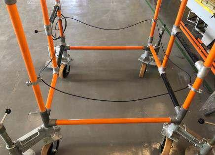
188 LADDERS, PLATFORMS AND INSULATING SCAFFOLD RITZ FERRAMENTAS E
FLV30489-1
FLV30707-1
FLV30490-1

Manual Hoists . . . . . . . . . . . . . . . . . . . . . . . . . . . . . 191 Link Stick For Hoists And Blocks. . . . . . . . . . . . 194 Insulating Pole for Hoists and Blocks . . . . . . . 194 Crossarm Gin . . . . . . . . . . . . . . . . . . . . . . . . . . . . . 195 Gin Pole for Load Lifting 195 Insulated Gin Pole / Cargo Boom .. . . . . . . . . . 197 Swivel Boom with Mast. . . . . . . . . . . . . . . . . . . . 198 Rope Blocks . . . . . . . . . . . . . . . . . . . . . . . . . . . . . . 202 Snatch Blocks . . . . . . . . . . . . . . . . . . . . . . . . . . . . . 204 Rope . . . . . . . . . . . . . . . . . . . . . . . . . . . . . . . . . . . . . 206 Rope Insulating Stick . . . . . . . . . . . . . . . . . . . . . . 208 Sling 209 Wire Grips. . . . . . . . . . . . . . . . . . . . . . . . . . . . . . . . . 210 Tarpaulin for Hot Line Tools. . . . . . . . . . . . . . . . 211 LOAD LIFTING TOOLS AND ACESSORIES GROUP F Access our site.
LOAD LIFTING TOOLS AND ACESSORIES
MANUAL HOISTS
Used in services of construction and maintenance of electrical networks for load handling. It has locking device for gradual descent of load which can be handled in two positions, to the right or to the left of the load application axis.
Hoists with Nylon Straps
Made with Ø 38mm RITZGLAS® fiberglass rod, traction mechanism and hooks made of metal, supplied in two handle versions: one with a plastic terminal (at the end for rubber glove work) and the other for hotstick work (via a handle with a rotating eye at the end). Its nylon straps can be purchased as replacement parts.
WARNING
The nylon-strap ratchet hoists are not considered insulation tools. For use in energized networks it is necessary to use insulating sticks compatible with the safety distance of table.


191 LOAD LIFTING TOOLS AND ACCESSORIES RITZ FERRAMENTAS F
Handle with plastic cap for rubber glove operation
Handle with butt-swivel for hot stick operation
GROUP F


The convertible nylon strap hoists are lightweight, sturdy, and versatile. Allow conversion of workload capacity of 0.75 ton. or 1.5 tons, simply by arranging the nylon straps.
192 RITZ FERRAMENTAS LOAD LIFTING TOOLS AND ACCESSORIES F
Catalog Reference Description A Insulating Length (mm) B Distance Between Hooks (mm) Approx. Weight. Min. Max kg lb RC309-0323 With regular handle 420 600 2500 6.30 13.89 RC309-0467 With hot stick handle 420 600 2500 7.20 15.85
HOIST WITH NYLON STRAP - 1 TON
A B A B A B
WITH NYLON STRAP - 2 TON Catalog Reference Description A Insulating Length (mm) B Distance Between Hooks (mm) Approx. Weight. Min. Max kg lb RC312-0000 With regular handle 770 500 1775 7.80 17.20 RC309-0468 With hot stick handle 770 500 1775 8.80 19.40
HOIST
RC309-0323
RC309-0451
RC309-0468
Catalog Reference Description A Insulating Length (mm) B Distance Between Hooks (mm) Approx. Weight. Min. Max kg lb RC309-0451 With regular handle 590 546 2740 (0.75 ton.) 1370 (1.5 ton.) 5.30 11.68 RC309-0452 With hot stick handle 650 546 2740 (0.75 ton.) 1370 (1.5 ton.) 5.60 12.34
CONVERTIBLE STRAP HOISTS (0.75 or 1.5 ton.)

To use the 0.75 ton load capacity, attach the load hook sheave to the free end loop of the strap.

To convert hoist load capacity from 0.75 ton. to 1.5 ton. keep the load hook sheave installed in the middle of the nylon strap when it is folded and with the end of the strap attached to the hoist body
Chain Ratchet Hoists
Lightweight and quick to operate, it has features for greater operator productivity when working in tight spaces because its drive handle operates on all sides of the load.
For easy coupling and load alignment, it has forged steel hooks with a safety lock and 360° swivel
For safety reasons, the chains are released for free-form movement only when there is no load.
The hoists have two control levers: the first to change movement direction; the second to activate the movement safety lock
Control levers are easy to operate even with gloves on.

193 LOAD LIFTING TOOLS AND ACCESSORIES RITZ FERRAMENTAS F
Catalog Reference Rated Working Capacity (ton.) Approx. Weight. kg lb 750E 0.75 7.30 16.09 1500E 1.50 11.50 25.35 3000E 3.00 17.00 37.48 6000E 6.00 23.00 50.70 1500E


LINK STICK FOR HOISTS AND BLOCKS
This equipment is designed to attach to crossarms in distribution lines, facilitating the traction of loads on the work structure. It is an indispensable tool for moving loads and pulling electrical and telephone cables
The link stick is manufactured with a RITZGLAS® insulating tube of Ø 32 mm, ensuring safety and durability. At one end, it has a Ø 3/4" hook, made of resistant steel and coated with black plastisol (final diameter of Ø 25 mm), with an opening of 127 mm, specifically designed to fit perfectly on distribution pole crossarms
On the other end, the stick is equipped with a swivel eye, made of galvanized steel, which allows the coupling of hoists and/or blocks for load traction, providing greater flexibility and adaptability at the workplace. In addition, the stick has an eye for a grip-all clampsticks, allowing the handling and positioning of the tool at a safe distance, ensuring that the work can be carried out efficiently and safely

INSULATING POLE FOR HOISTS AND BLOCKS
They can safely transform a nylon strap hoist or block into insulating equipment to use it in energized installations
It has a steel safety hook at one end and a steel swivel eye at the other. Its eye is mounted to one of the hoist or block hooks to ensure its insulation from the grounded parts of the structure.
194 RITZ FERRAMENTAS LOAD LIFTING TOOLS AND ACCESSORIES F Catalog Reference Ø (m) Insulating Lenght (mm) Rated Work Capacity Approx. Weight. daN lb kg lb RC400-1175 32 407 2000 4409 2.00 4.40 RC400-2399 487 2.40 5.30 RC400-2400 637 3.10 6.80
RC400-1175 Catalog Reference Insulating Lenght (mm) Rated Work Capacity Approx. Weight. daN lb kg lb FLV30486-1 547 670 1506 2.64 5.82
CROSSARM GIN
Provided with clevis type saddle to fit over distribution crossarms, allowing the use of blocks or ropes to lift the conductors from the insulators
RH20 and RT400-0870 can be inverted and have a removable galvanized steel pin for better adjustment on the crossarm.

GIN POLE FOR LOAD LIFTING
Lightweight, mechanically resistant tools that are easy to install and provide significant gains in safety and productivity for lifting equipment and materials They are ideal for the construction and maintenance of medium voltage overhead networks
Manufactured with cast aluminum metal components and RITZGLAS® insulating tube, our gin pole are synonymous with durability and efficiency.
NOTES
- The gins poles are designed for vertical lifting applications. They are not suitable for lateral traction on the hand or misaligned load rope. The force direction must always be parallel and aligned with the gin pole.
- When calculating the load capacity, take into account a 10% loss due to friction on the traction ropes
Using a double block lift system, the maximum load to be lifted will be 635 daN (1400 lbs). A snatch blocks must be attached to the base of the structure to guide the hand rope of the block
With a single lifting system, the maximum load will be 408 daN (900 lbs). The lifted load plus the pulling force and the friction force equals the gin's capacity.
195 LOAD LIFTING TOOLS AND ACCESSORIES RITZ FERRAMENTAS F
Catalog Reference Description Crossarm Dimensions (mm) Rated Work Capacity Max Angle 30º Insulating Length (m) Approx. Weight. daN lb kg lb FLV08257-3 No convertible 75 x 75 340 750 0.71 7.70 16.96 RH20 Convertible 89 x 114 to 21 x 146 340 750 0.71 7.70 16.96 RT400-0870 Convertible 227 500 1.06 8.20 18.00


|
RC400-0090
With chain-mounted pole saddle through a 920 mm chain, it can only be mounted in open areas of the pole (does not have a distancing saddle).
|
RC400-0315
With a 130 mm spacer saddle for fixing to the pole through a 920 mm chain, it has a coupling with a spacer saddle, allowing its installation next to crossarms. Its coupling to the pole is done by a chain tensioner and tightened with a manual steering wheel.
|
RC400-0578
With a direct fixing system, it is compatible with both "T" double-pole and circular poles. For "T" double-poles, fixing is done with two screws and thumbscrew, using the pole's own holes. For circular poles, fixing is done with the help of two conventional metal straps
With four available fixing positions, it is important to observe the following nominal working capacities for each position.
st1 hole: 100 daN (220 lb) at base side
nd2 hole: 150 daN (330 lb)
rd3 hole: 200 daN (440 lb)
th4 hole: 250 daN (550 lb) at upper side
GINS FOR LOAD LIFTING
196 RITZ FERRAMENTAS LOAD LIFTING TOOLS AND ACCESSORIES F
RC400-0315
RC400-0090
Catalog Reference Rated Work Capacity Ø (mm) Length (m) Approx. Weight daN lb Insulating Total kg lb RC400-0090 907 2000 76 0.54 0.68 7.10 15.65 RC400-0315 907 2000 76 0.52 0.68 9.80 21.60 RC400-0578 100 to 250 220 to 550 64 1.05 1.83 12.20 26.90
RC400-0578
INSULATED GIN POLE / CARGO BOOM
The heavy load lifting gin is made with RITZGLAS® square tube and has three chain stretchers, with handwheels for coupling to the structures.
The square head at the top of the pole has two shackles for easy load fixing
By attaching a pole clamp to the coupling on top of this pole, a wire tong can be used for increased stabilization.
The load lift boom has a square pole clamp (RE400-0434) installed near its end This clamp can be adjusted in three positions for better positioning of the lifting load as well as its retention to the structure
The lower coupling hinged saddle allows the boom to be moved 90°, i.e. from horizontal to vertical and vice versa, as well as to rotate 180°. Its upper head is similar to that of the gin pole.
NOTE
Rated work loads include pulling force.
GIN POLE
CARGO BOOM


SPARE PART
197 LOAD LIFTING TOOLS AND ACCESSORIES RITZ FERRAMENTAS F
RE400-0434 RC400-0470 RC400-0475
Catalog Reference Size (mm) £ Insulating Length (m) Rated Work Capacity Approx. Weight. daN lb kg lb RC400-0470 100 x 100 2.28 2268 5000 33.20 73.19 RC400-0472 3.50 40.40 89.07
Catalog Reference Size (mm) £ Insulating Length (m) Rated Work Capacity Mountin g Approx. Weight. daN lb kg lb RC400-0475 100 x 100 4.72 454 1000 Pole 45.60 100.53 RC400-0483 Tower 45.00 99.21
Catalog Reference Description Approx. Weight. kg lb RE400-0434 Square pole clamp for cargo boom 4.00 8.82


SWIVEL BOOM WITH MAST

The boom pole with mast is intended for heavy duty high voltage structures, particularly for removing insulator chains with the aid of the cradle.
In the boom poles with mast (RC400-0469 and RH1973/H-10) two saddles (R070496) already included are used to attach the gin to the pole: one at the top and one at the bottom. These saddles have handwheel chain stretchers
In the boom poles with mast (RC400-0464, RC400-0465 and RH1973-814), designed for tower mounting, two hardware models are used: a saddle (RC400-0602) mounted on the underside, which is attached to the tower, with two sets of screws and angle jaws, and a triple fork (FLV01644-1), already included, installed on the upper side, for coupling the trolley poles.
When the mast is not necessary, the adapter (FLV18133-1) must be used to couple the boom to the saddle (RC400-0602).
The coupling and the formation of the mast stabilization tripod on the metal frame are made by three trolley poles (RH4721-112) and respective metal frame saddles (RM4742-3), both specified separately.
The trolley pole have heat-treated aluminum alloy heads and forged steel swivel eye.
On all models, the mast is held in the mast with a strain link stick (RC400-0816) and a hoist (1500E), both specified separately.
The mobile pole clamp on the square boom (RC400-0464, RC400-0465 and RC400-0469) can be adjusted to three different positions for easy operation of the assembly at different angles of the insulator chain. The boom has at its end an auxiliary head with two shackles for retaining or holding additional loads, tools, etc
198 RITZ FERRAMENTAS LOAD LIFTING TOOLS AND ACCESSORIES F
RC400-0602
FLV01644-1
RH4721-112
FLV18133-1
R070496

NOTE
The swivel boom with mast has the rated working capacity above only when mounted with the arm support tripod, consisting of 3 trolley poles, 1 strain link stick, and 1 2-ton hoist (purchased separately).
199 LOAD LIFTING TOOLS AND ACCESSORIES RITZ FERRAMENTAS F
Catalog Reference Composition of the Set Approx. Weight. Ø 76 mm Mast Insulating Length (m) £ 100 x 100 mm Boom Insulating Length (m) Rated Work Capacity daN lb kg lb RC400-0464* 2.30 4.72 454 1000 01 01 - 58.50 128.97 RC400-0465* 2.91 5.33 01 01 - 63.90 140.88 RC400-0469** 2.91 5.33 - - 02 63.90 140.88
SWIVEL BOOM WITH MAST - HEAVY DUTY
* Metal structure coupling | ** Pole coupling
Mast
RC400-0602 FL V01644-1 R070496
Boom


The square swivel boom extension is used to bring the electrician to potential through the potential access chair (FLV12563-1).
It has two Ø 76 mm bronze alloy pole clamp (FLV00196-5) for coupling to the square head and the square pole clamp of the boom pole. It also has a head with two eyes, one for installation of the potential access chair and other for bracing with an insulating pole and block.
EXTENSION FOR SQUARE SWIVEL BOOM WITH MAST
200 RITZ FERRAMENTAS LOAD LIFTING TOOLS AND ACCESSORIES F
FLV18617-1
Catalog Reference Ø (mm) Insulating Length (m) Rated Work Capacity Approx. Weight. daN lb kg lb FLV18617-1 76 4.00 140 309 16.64 36.68
SWIVEL BOOM WITH MAST - MEDIUM DUTY
of the Set
* Metal structure coupling. | ** Pole coupling

(Items 2 through 8: separate specifications)
NOTE
For loads greater than 272 daN (600 lb) we suggest using the metal frame saddle (RM4742) with a 76 mm bronze alloy pole clamp (FLV00196-5) and an identical rear pole clamp to prevent slippage of the trolley pole used on the mast support tripod
ACCESSORY FOR SWIVEL BOOM WITH MAST
201
LIFTING TOOLS AND ACCESSORIES RITZ FERRAMENTAS F
LOAD
Catalog Reference Composition
Approx. Weight. Ø 76 mm Mast Insulating Length (m) Ø 76 mm Boom Insulation Length (m) Rated Work Capacity daN lb kg lb RH1973-814* 2.30 4.09 227 500 01 01 - 38.80 85.54 RH1973/H-10** 1.68 2.87 272 600 - - 02 27.60 60.85
RC400-0602 FL V01644-1 R070496
Catalog Reference Description Approx. Weight. kg lb R070496 Saddle 7.00 15.43 RC400-0602 Saddle for Tower Bracket 10.30 22.70 FLV01644-1 Triple Fork 1.95 4.30 FLV00196-5 Bronze alloy pole clamp Ø 76 mm 2.62 5.78 FLV18133-1 Swivel Boom adapter to the structure 1.00 2.20
5 - RM4742-3 6 - RH4722 1 - RH1973-814 2 - RE402-0141 3 - RC400-0816 4 - 1500E 7 - RH1950-90 8 - RH1950-9
ROPE BLOCKS
With thermoplastic housings and sheaves, steel hooks with safety locks (with continuous rotation on their shaft), it provides easier coupling and alignment with the load.
When only blocks are purchased, we note that the pairs are formed with one block unit with rope becket (FLV10893-1) and another unit without this device (RC400-0918).
Common Rope Blocks
Equipped with an eye for hot-stick mounting.
Block dielectric strength: 30 kV
Light Block
Compact and resistant, this tool has been specially developed for use in electrical and telecommunication, lifting loads, cable pulling, gins, etc
It has 15 meters of rope (RM1895-2).
202 RITZ FERRAMENTAS LOAD LIFTING TOOLS AND ACCESSORIES F


203 LOAD LIFTING TOOLS AND ACCESSORIES RITZ FERRAMENTAS F
Catalog Reference Description Rated Work Capacity Approx. Weight. daN lb kg lb RC400-0914 Complete double block mounted with 38 m rope (RM1895-3) 1589 3500 7.20 15.87 RC400-0915 Complete triple block mounted with 45 m rope (RM1895-3) 1589 3500 7.90 17.40 RC400-0925 Triple block with 45m Polydracon rope (RM1896-3) 1589 3500 8.00 17.5 RC400-0916 Single block (1 sheave) without becket 907 2000 0.96 2.10 RC400-0917 Single block (1 sheave) with becket 907 2000 1.05 2.30 RC400-0918 Triple block (3 sheaves) without becket 1589 3500 2.00 4.40 FLV10893-1 Triple block (3 sheaves) with becket 1589 3500 2.00 4.40 RC400-0919 Double block (2 sheaves) without becket 1589 3500 2.00 4.40 FLV16813-1 Block for double block (2 sheaves) with becket 1589 3500 2.00 4.40 FLV07777-1 Complete lightweight double block with 15 m rope (RM1895-2) 400 880 2.10 4.62
ROPE BLOCKS
RC400-0918
RC400-0915 FLV07777-1
RC400-0917
FLV10893-1
RC400-0916
SNATCH BLOCKS
Indispensable equipment in cargo handling and lifting operations in construction and maintenance work in electrical and telephone installations
The two versions of hooks available (drawn or forged steel) are designed for easy mounting of the snatch block to their installation location.
The body and sheave are constructed of heat treated aluminum alloy and have a folding device to allow the introduction of a quick swiveling service rope over the sheave.
The RC417-6067 and R2230-1 have forged steel hooks and safety lock, and the R2230-2 have a cold drawn steel hook without safety lock
The rope hook is made of stainless steel and is designed for easy lifting of loads or tools. It has two holes to mount the rope and its tip is slightly curved for easy tool introduction.
NOTES
- For safety reasons, hoisted equipment should always be seated on the hook bed when transporting
- The spool bracket (RM1979) is made with angle bracket, continuously rotating forged steel eye for spool support, bronze claws, two steel bolts and wing nuts for attachment to the metal frame.
- The five holes in the snatch block holder allow them to fit differently sized metal structures.
204 RITZ FERRAMENTAS LOAD LIFTING TOOLS AND ACCESSORIES F Description Catalog Reference
A/ 2 A A/2 A/2 A = Rated Working Capacity
ALUMINUM SNATCH BLOCKS
SNATCH BLOCKS ACCESSORY


205 LOAD LIFTING TOOLS AND ACCESSORIES RITZ FERRAMENTAS F
RC417-6067
R2230-2
Catalog Reference Description Rated Work Capacity Approx. Weight daN lb kg lb RM1849 Stainless steel alloy rope hook It has two holes for rope mounting 250 551 0.30 0.67 FLV29635-1 Stainless steel alloy rope hook. It has two holes rope mounting with safety lock 250 551 0.31 0.68 RM1979 Aluminum snatch block support with fitting for metal frame mounting and 76 x 76 mm flaps and total length of 475 mm 567 1250 6.00 13.20 R2230-1
Catalog Reference Description Rated Work Capacity Approx. Weight. daN lb kg lb RC417-6067 For ropes up to Ø 5/8”, with forged steel hook and safety lock 1134 2500 2.60 5.70 R2230-1 For ropes up to Ø 5/8”, with forged steel hook and safety lock 567 1250 1.10 2.42 R2230-2 For ropes up to Ø 5/8”, with drawn steel 567 1250 1.0 2.42
RM1849
RM1979
FLV29635-1
ROPE
Polypropylene Rope
The polypropylene rope was selected for its mechanical strength, reduced elongation, and lightness
This rope, like all other ropes for hot line work, should always be kept clean and stored in a dry place and sheltered from the sun.
Although the polypropylene rope has good dielectric strength when new, it is not insulating for hot line work Therefore, if it contacts energized parts, an insulating rope spacer must be used with it.
It comes in white color, with three-legged polypropylene multifilament formation and a 220 meter roll.

* 20% of minimum breaking strength
206 RITZ FERRAMENTAS LOAD LIFTING TOOLS AND ACCESSORIES F Catalog Reference Ø Rated Working Capacity Minimum Breaking Strength Approx. Weight. in. mm daN lb daN lb kg/m lb/m RM1895-1 1/4" 6.00 107 236 537 1184 0.02 0.04 RM1895-2 3/8" 9.50 230 507 1153 2542 0.04 0.09 RM1895-3 1/2" 12.50 402 886 2010 4430 0.07 0.15 RM1895-4 5/8" 15.50 582 1283 2910 6415 0.12 0.26 RM1895-5 3/4" 19.00 734 1618 3670 8090 0.17 0.37
Polydacron Rope
Three-legged fiber twisted rope combined with excellent service life and high strength-to-weight ratio The rope is made of high-strength polyester surface yarns wrapped in high tenacity polyolefin fiber. It also offers the durability of polyester, but with greater strength than other ropes due to the combination with polyolefin fiber.
The rope is not considered insulating for hot line work Therefore, if it contacts energized parts, an insulating rope spacer must be used with it.
Supplied in a 183-meter roll.


Safety Rope
Rope woven into three strands of polyester multifilament and central core of polyamide multifilament, lightweight and with good mechanical resistance.
For specific use in hanging chairs and safety guide cable for securing fall arrest and lifeline installation.
This rope is not considered insulating for work on energized installations.

*
207 LOAD LIFTING TOOLS AND ACCESSORIES RITZ FERRAMENTAS F Catalog Reference Ø Rated Working Capacity* Minimum Breaking Strength Approx. Weight. in. mm daN lb daN lb kg/m lb/m RM1896-2 3/8" 9.50 335 740 1700 3700 0.05 0.11 RM1896-3 1/2" 12.50 560 1240 2800 6200 0.09 0.20 RM1896-4 5/8" 15.50 815 1800 4100 9000 0.14 0.31
20% of minimum breaking strength
*
Catalog Reference Roll Length Ø Rated Working Capacity* Minimum Breaking Strength Approx. Weight m mm daN lb daN lb kg/m lb/m RM1897-50 50 12 460 1012 2300 5060 0.108 0.237 RM1897-100 100 RM1897-200 200 RM1897-250 250
20% of minimum breaking strength
Semi-Static Rope
Nylon (core) and high-tenacity polyester (sheath) rope is provided in black and orange colors, with a multifilament construction, twisted into three strands. It has good mechanical strength, reduced elongation, and lightness.
The rope is not considered insulating for work on energized installations. Therefore, in the case of direct contact with energized parts, it is necessary to use an insulating rope separator in series with it. Supplied in a 100-meter roll.

ROPE INSULATING STICK
It is used in series with the polypropylene rope when its direct contact with live parts of the installation is likely
It is made with RITZGLAS® tube, heat treated aluminum alloy heads, and forged steel swivel eyes.

208 RITZ FERRAMENTAS LOAD LIFTING TOOLS AND ACCESSORIES F Catalog Reference Ø (mm) Insulating Length (m) Rated Working Capacity Approx. Weight. daN lb kg lb FLV04803-1 25.4 0.42 800 1764 0.63 1.39 FLV04803-2 1.04 0.95 2.09 FLV04803-3 1.54 1.15 2.54
Catalog Reference Ø Rated Working Capacity* Minimum Breaking Strength Approx. Weight. in. mm daN lb daN lb kg/m lb/m RM1898-100 7/16" 11 700 1570 3500 7900 0.10 0.22
20% of minimum breaking strength
*
SLING
The webbing slings (non-insulating) have been designed to couple loads to the respective tools or traction equipment and from these to the work structure. They are therefore widely used in cargo handling and traction of electrical and telephone cables. Models made without any metal components are easy to handle and pack due to their flexibility.
They are available in two basic types:
“Return Eye’’ Style
One size only. This model was primarily designed for the hanger arrangement, but can also be used with upright hooks and basket.
‘’Endless’’ Model
With five size options. This is the most versatile model of all. It can be used in vertical, hanger or basket arrangements, and adapts well to the shape of the load. It provides greater grip strength and upright support. It's easier to use and longer lasting because it has no eyes that establish wear points.
POLYESTER WEBBING SLINGS


209 LOAD LIFTING TOOLS AND ACCESSORIES RITZ FERRAMENTAS F A
Catalog Reference Width (mm) Length (m) Rated Working Capacity by lifting type Type Basket Strength Vertical up to 45º from 45º to 60º daN lb daN lb daN lb daN lb daN lb RC417-0133 60 1.83 4000 8818 1600 3527 2000 4410 2800 6173 2000 4410 Return Eye RC417-0134 30 0.92 2000 4410 800 1764 1000 2205 1400 3086 1000 2205 Endless RC417-0135 30 1.22 2000 4410 800 1764 1000 2205 1400 3086 1000 2205 RC417-0136 30 1.52 2000 4410 800 1764 1000 2205 1400 3086 1000 2205 RC417-0137 30 1.83 2000 4410 800 1764 1000 2205 1400 3086 1000 2205 RC417-0138 30 2.44 2000 4410 800 1764 1000 2205 1400 3086 1000 2205 RC417-0139 60 0.92 4000 8818 1600 3527 2000 4410 2800 6173 2000 4410 RC417-0140 60 1.22 4000 8818 1600 3527 2000 4410 2800 6173 2000 4410 RC417-0141 60 1.52 4000 8818 1600 3527 2000 4410 2800 6173 2000 4410 RC417-0142 60 1.83 4000 8818 1600 3527 2000 4410 2800 6173 2000 4410 RC417-0143 60 2.44 4000 8818 1600 3527 2000 4410 2800 6173 2000 4410
RC417-0133
RC417-0134
Nylon looped slings are made with nylon strap, providing more malleability and grip without damaging the object being handled.
They come in three different lengths with equal load capacity in the three configurations: basket, hanger, and vertical.
They have steel rings at their ends, with surface treatment in D-shape, for easy mounting with a hot stick.


WIRE GRIPS
Intended for hot line conductor straining
The movable grip on top provides its installation to the conductor by using an insulating hot stick and also, when loose, it can be used as a locking device, preventing it from falling off accidentally.
The DR (Double Round) jaw shape is suitable for aluminum and copper cables
210 RITZ FERRAMENTAS LOAD LIFTING TOOLS AND ACCESSORIES F
Catalog Reference Width (mm) Insulating Length (m) Rated Work Capacity Approx. Weight. daN lb kg lb FLV06619-1 50 0.50 670 1477 0.55 1.21 FLV06619-2 0.80 0.65 1.43 FLV06619-3 1.20 0.75 1.65 Catalog Reference Conductor Ø (mm) Rated Capacity Jaw Approx. Weight. Work Rupture Minimum Maximum daN lb daN lb Type Material kg lb 51.E07.D20-CE 5.08 10.16 800 1764 2000 4409 DR Bronze 1.48 3.26 51.E07.D30-CE 7.87 13.50 800 1764 2000 4409 1.90 4.19 51.E07.D40-CE 13.41 18.80 1700 3748 3600 7937 3.50 7.72 51.E07.D50-CE 18.80 21.80 1700 3748 3600 7937 3.50 7.72
Jaw
FLV06619-2
DR
TARPAULIN FOR HOT LINE TOOLS
It is used as a soil cover for the purpose of placing the selected tools for interventions in installations. In addition to protecting them against contamination, it establishes a place for inspection and selection of equipment to be used.
This tarpaulin is made of double-sided vinyl

211 LOAD LIFTING TOOLS AND ACCESSORIES RITZ FERRAMENTAS F Catalog Reference Dimensions (m) Approx. Weight. kg lb RT306-0014 4 x 3 9.15 20.17
212 RITZ FERRAMENTAS LOAD LIFTING TOOLS AND ACCESSORIES F

Wire Tongs . . . . . . . . . . . . . . . . . . . . . . . . . . . . . . . . 215 Wire Tong Band . . . . . . . . . . . . . . . . . . . . . . . . . . . 219 Wire Tong Blocks Clamp 220 Wire Tong Swivel . . . . . . . . . . . . . . . . . . . . . . . . . . 221 Saddle and Components . . . . . . . . . . . . . . . . . . 221 Tower Type Saddles 226 Dual Auxiliary Arm . . . . . . . . . . . . . . . . . . . . . . . . 227 Auxiliary Crossarms . . . . . . . . . . . . . . . . . . . . . . . 230 Extension Arm 231 Auxiliary Crossarm Support for Aerial Device . . . . . . . . . . . . . . . . . . . . . . . . . . . . . . 232 Temporary Conductor Support . . . . . . . . . . . . 233 Hot Stick Tension Puller 235 Symmetrical Tension Puller . . . . . . . . . . . . . . . . 236 Strain Link Stick . . . . . . . . . . . . . . . . . . . . . . . . . . . 236 Spiral Link Stick 238 Roller Link Stick . . . . . . . . . . . . . . . . . . . . . . . . . . . 239 Strain Pole Clevis-Eye / Clevis-Clevis . . . . . . . 240 Adjustable Strain Poles . . . . . . . . . . . . . . . . . . . . 241 Sectional Strain Pole (with Splice). . . . . . . . . . 243 Light-weight Strain Carrier 244 Distribution Strain Carrier . . . . . . . . . . . . . . . . . 248 Two-Pole Strain Carrier 250 Auxiliary Strain Carrier. . . . . . . . . . . . . . . . . . . . . 252 Accessories for Strain Carrier 254 Heavy-Duty Suspension Link Stick . . . . . . . . . 256 Adjustable Hook Assembly 257 Suspension Pole with Adjustable Hook . . . . 257 Yoke . . . . . . . . . . . . . . . . . . . . . . . . . . . . . . . . . . . . . . 258 Static Ground . . . . . . . . . . . . . . . . . . . . . . . . . . . . . 263 Cradle. . . . . . . . . . . . . . . . . . . . . . . . . . . . . . . . . . . . . 264 “J”- Hook Assembly. . . . . . . . . . . . . . . . . . . . . . . . 270 Trolley Pole. . . . . . . . . . . . . . . . . . . . . . . . . . . . . . . . 271 CONDUCTOR SUPPORT EQUIPMENT GROUP G Access our site.
CONDUCTOR SUPPORT EQUIPMENT GROUP G
WIRE TONGS
It is generally used to hold and move energized conductors from their original positions. It allows electricians to service crossarms, insulators, removing and placement of poles and hardware, as well as mounting new components, such as lightning arresters, in overhead lines
This stick is usually operated in pairs or with other complementary tools such as: saddles; clamps; blocks. All are specially designed for quick and safe service.
Constructed with RITZGLAS® tube and aluminum alloy fittings (for better mechanical strength and lightness ratio), the steel swivel eye has a bearing for smooth and perfect rotation.
The varying wire tong jaw opening allows the conductor to be firmly and securely fixed by rotating the bar until the jaw is fully closed.
215 CONDUCTOR SUPPORT EQUIPMENT RITZ FERRAMENTAS G
The diagrams show correct orientation of the use of the wire tongs through the four most used configurations and their workloads.
The electrician must strictly observe the safety distances when using the hot line poles, according to their recommended voltages in the OSHA table.

Wire tong with saddle, wire tong blocks clamp, and conductor pulling blocks.
WORKING LOADS*

Wire tongs with saddles, wire tong band, and conductor pulling block.
* Based on a fully horizontal wire tong. The lower the upper saddle is placed, below the conductor's level, the higher the tension on pole “A” will be, so the load it can support will be lower
216 CONDUCTOR SUPPORT EQUIPMENT RITZ FERRAMENTAS G
Figure Nº
Pole Dimensions Ø (mm) / Length (m) Support Type Max. Workload (per Conductor) Maximum Conductor Size and Span (m) ACSR Copper A B daN lb Size Span Size Span 1 51 x 3.55 38 x 2.96 Pole saddle and lift saddle 125 276 4/0 213 4/0 91 64 x 3.51 215 474 366 152 2 51 x 3.55 38 x 2.96 Pole saddle and lift saddle 125 276 4/0 213 4/0 91 64 x 3.51 215 474 366 152
RITZGLAS®
B A Load B Block A Block clamp 762mm

Wire tongs, lift saddle, tourniquet pull pole and block used to pull heavy conductors.
WORKING LOADS

Set for lifting the three phases where all three conductors are raised simultaneously.
WARNING
WORKLOADS - For the correct selection of tools, the loading information of the structure must be used. When these values cannot be obtained, the whole work structure must be analyzed before the load is applied
When calculations are not possible (e.g. when a pole is slightly larger than its adjacent pole) just consider the total weight of the adjacent spans as the maximum workload This does not apply to structures installed at high points, which requires special analysis for load determination.
If the workload is higher than indicated in the table (for a specified pole), use two wire tongs with double lift saddle or use a larger Ø wire tong.
217 CONDUCTOR SUPPORT EQUIPMENT RITZ FERRAMENTAS G
Nº RITZGLAS® Pole Dimensions Ø (mm) / Length (m) Support Type Max. Workload (per Conductor) Maximum Conductor Size and Span (m) ACSR Coppe A B C daN lb Size Span Size Span 3 51 x 3.55 38 - Lift Saddle 160 353 4/0 259 4/0 114 64 x 3.51 454 1000 397.5 350 250 259 4 64 x 3.51 51 x 2.33 51 x 2.33 Pole Saddles 102 225* 4/0 168 4/0 70
With maximum lift
1.52m above the saddle and maximum
102 daN/225 lb on one side. A Load B B C A 610 mm 1520 mm 1830 mm
Figura
*
of
unbalance of

The RH4647-16 is spliced wire tong, making it easy to carry.
The connection between the two parts is made through a metal splice, of galvanized and fixed steel, with steel pin and pin type cotter pin.
218 CONDUCTOR SUPPORT EQUIPMENT RITZ FERRAMENTAS G
Catalog Reference Ø (mm) Insulating Length (m) Total Length (m) Conductor Ø (mm) Rated Work Capacity (traction) Storage (optional) Approx. Weight Min. Max. daN lb kg lb RH4645-6 38 1.74 1.99 4.10 57.00 340 750 FLV18339-13 3.30 7.28 RH4645-8 38 2.35 2.60 340 750 FLV18339-3 3.80 8.38 RH4645-10 38 2.95 3.20 340 750 FLV18339-4 4.20 9.26 RH4646-6 51 1.72 1.99 454 1000 FLV18339-13 4.60 10.14 RH4646-8 51 2.31 2.58 454 1000 FLV18339-3 5.30 11.68 RH4646-10 51 2.94 3.20 454 1000 FLV18339-4 6.00 13.23 RH4646-12 51 3.60 3.87 454 1000 FLV18339-5 7.50 16.53 RH4647-8 64 2.29 2.61 567 1250 FLV18339-3 7.30 16.09 RH4647-10 64 2.90 3.21 567 1250 FLV18339-4 8.40 18.52 RH4647-12 64 3.45 3.77 567 1250 FLV18339-5 9.40 20.72 RH4647-14 64 4.12 4.44 567 1250 FLV18339-14 10.40 22.93 RH4647-16* 64 4.74 5.06 567 1250 FLV18339-3 13.90 30.64 RC400-0171 76 3.45 3.78 680 1500 FLV18339-5 12.70 28.00 RC400-0172 76 4.21 4.54 680 1500 FLV18339-14 14.90 32.85
WIRE TONGS
Insulating Length
* Spliced wire tong
WIRE TONG BAND
They are installed in the wire tong to be used as a pulling point in the block, for the articulation of these poles during the removal and subsequent approach of the conductor.
To ensure effective insulation between the block and live conductors, the clamp must be installed on the pole at a minimum distance according to its voltage class or more.
This tool is built in four different diameters, with a ring for direct contact with the pole and in aluminum alloy for the free rotation of the pole, once mounted to it, through two screws. The lifting eye is made of bronze alloy and has a pivot to follow the pull tool to the pole.


219 CONDUCTOR SUPPORT EQUIPMENT RITZ FERRAMENTAS G Block clamp Catalog Reference Ø (mm) Load Capacity Approx. Weight daN lb kg lb RM1729 51 680 1500 0.61 1.34 RM1729-1 64 0.65 1.43 RM1729-2 76 0.70 1.54 RM1729-3 38 0.33 0.73

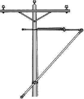
WIRE TONG BLOCKS CLAMP
Designed as a mounting point for wire tong pulling, with the aid of a block, which is connected to the block clamp eye This arrangement aligns the pulling forces with the wire tong, helping to lift heavy conductors back to their original position.
The clamp is made of aluminum alloy, whose ring is the tightening screw and with a wing nut in bronze alloy.
The inner walls of the clamp are lined with a stainless steel blade, protecting the surface of the pole from mechanical damage.
The clamp consists of two halves, which are open for coupling and mounting to the pole by tightening the wing nut installed on one of the clamp tabs.
The wing nut device has a spring for easy, quick, and safe clamp operation.
220 CONDUCTOR SUPPORT EQUIPMENT RITZ FERRAMENTAS G Catalog Reference Ø (mm) Rated Work Capacity Approx. Weight daN lb kg lb RM4743 38 560 1235 1.10 2.43 RM4743-1 51 1.20 2.65 RM4743-2 64 1.20 2.87
Wire tong block Ring
WIRE TONG SWIVEL
Useful tool for a safe movementation of conductor through the arrangement of two wire tongs
The Wire Tong Swivel have four different diameters models The tool structure is made by a direct contact ring to the pole, a shackle, both made of aluminum alloy, besides the circular handles made of bronze alloy.
The contact ring is installed on the body of the wire tong head, which is coupled to the conductor. The other wire tong is attached to the collar strap, forming a pivoting assembly. Thus, the collar prevents two wire tongs, connected on the same cable, from twisting or event breaking it.
Meets the requirements of the IEC61236 standard.


SADDLES AND COMPONENTS
| RM1846-W
Saddle of rope lashing for poles , it has six ring is a simple and practical tool where the ropes can be tied, avoid undue embarrassment of them.
It has chain tensioner (RM1848-W) with a length of 915 mm for coupling to the pole with steering wheel to make the final adjustment. Made of heat treated aluminum alloy to meet the demands of work load and lightness in handling.

221 CONDUCTOR SUPPORT EQUIPMENT RITZ FERRAMENTAS G Catalog Reference Ø (mm) Rated Work Capacity Approx. Weight daN lb kg lb FLV16599-1 38 270 607 0.85 1.87 RM4745 51 270 607 0.90 1.98 RM4745-1 64 270 607 0.98 2.16 RM4745-2 76 270 607 1.10 2.42
RM1846-W
RM4744


RM4760-1W

RC400-1016
FLV4740-18W
FLV4740-19W
FLV4740-20W
Manufactured in according to standard IEC-61236.
This tool is used as a coupling point for poles, blocks, or masts, allowing the hot poles to move away from the utility pole.
Available models include: saddles with clamp; with extension and clamp; with shackle and with extension and shackle.
Base made of heat treated aluminum alloy and stainless steel chain coupling to meet the demands of work load and lightness in handling, shackle and saddle coupling made of cast bronze. It has chain strecher (FLV00049-3) with length of 915 mm for coupling to the pole with steering wheel to make the final adjustment.
| RM4744
Crossarm type saddle, useful for reduced workspace or already mounted with one or more pole saddles The shackle installed on the saddle body, in turn, provides freedom of movement and allows the wire tong to move freely in either direction. It can be used on 76 x 108 mm and 102 x 203 mm.
| | RM4760-W ( RM4760-1W Simple) (double)
Lifting saddle intended for coupling point connection of stick, rope blocks or masts for spacing from poles in "H" type frameworks or whenever the working clearance is too limited.
Made with base and shoe of heat treated aluminum alloy to meet the demands of work load and lightness in handling, support strap and chain coupling made of steel, and saddle strap made of cast bronze. It has chain tensioner (RM1848-W) for coupling to the pole with steering wheel to make the final adjustment. It is equipped with strap and pin for connection of the rope block and wire tong respectively, allowing the free movement of both.
| RC400-1016
The single lift saddle, belonging to the group of conductor support equipment. Made of RITZGLAS® This saddle is equipped with a handle and pin to connect the block and wire tong, respectively, allowing free movement of both.
Used when the work space on the pole is limited, provides a total conductor lift of up to 915 mm. With the same load capacity as the aluminum lift saddles, but normally used in higher voltage systems where more room is needed to lift the conductors
222 CONDUCTOR SUPPORT EQUIPMENT RITZ FERRAMENTAS G
| | | |
RM4760-W
FLV4740-3W FLV4740-4W FLV4740-5W FLV4740-9W
| | | |
FLV4740-10W FLV4740-15W FLV4740-16W FLV4740-17W
| | |
SADDLE

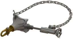


223 CONDUCTOR SUPPORT EQUIPMENT RITZ FERRAMENTAS G
Catalog Reference Description Rated Work Capacity Approx. Weight daN lb kg lb RM1846-W Rope tie saddle 454 1000 3.40 7.50 FLV4740-3W Saddle and tightener with 38 mm clamp 454 1000 4.90 10.80 FLV4740-4W Saddle and tightener with 51 mm clamp 454 1000 5.00 11.02 FLV4740-5W Saddle and tightener with 64 mm clamp 454 1000 5.10 11.24 FLV4740-9W Saddle and tightener with 76 mm clamp 454 1000 8.85 12.90 FLV4740-10W Saddle and tightener less clamp 454 1000 4.10 9.04 FLV4740-15W Saddle with mounting eye 454 1000 3.40 7.50 FLV4740-16W Saddle with extension and 38 mm clamp 363 800 5.40 11.90 FLV4740-17W Saddle with extension and 51 mm clamp 363 800 5.50 12.10 FLV4740-18W Saddle with extension and 64 mm clamp 363 800 5.60 12.35 FLV4740-19W Saddle with extension and 76 mm clamp 363 800 5.70 12.57 FLV4740-20W Saddle with extension and shackle 363 800 4.60 10.15 RM4744 76 x 108 to 102 x 203 mm adjustable opening crossarm saddle 227 500 2.50 5.51 RM4760-W Simple lift saddle 454 1000* 5.83 12.85 RM4760-1W Double lift saddle 340 750* 6.40 14.11 RC400-1016 Single lift saddle with RITZGLAS® insulating tube 454* 1000* 8.50 18.70
FLV4740-4W FLV4740-16W FLV4740-20W FLV4740-10W FLV4740-15W
* For each wire tong
RC400-0073

Saddle Components
| RC400-0073
RM1848-W

RM1847

RM4740


RM4740-14
RM4741-3

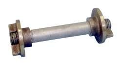
RM4760-2
The saddle extension provide additional spacing between the sticks and the post, fixed to each other through the saddle. It has at one end preparation for coupling in the saddles through tear with appropriate geometry for fitting and drilling for installation of locking screw At its other end, have a hole for fastening the pole clamp Tool made of cast aluminum alloy with heat treatment so that the resistance is compatible with the efforts of its application
| RM1848-W
The chain wheel tightener is a component of different models of sadlles, it´s responsible fastening the sadlle to the pole and the final adjustment is possible by using the tightening wheel. The chain wheel tightener provides easy installation of the sadlles, preventing it from sliding down or moving excessively, keeping it firm to its location. Haft manufactured in aluminum alloy, fork in micro-casting steel, stainless steel tightening wheel, welded link chain and safety pin.
| | | | RM1847 RM1847-3 RM1847-4 RM1847-6
The length of the chain stretcher can be increased by using the chain extension for poles with larger diameters. Coupling made of heat treated aluminum alloy, attached to a chain made of steel and anticorrosive surface treatment. It has a safety pin also made of steel and with anti-corrosion treatment, which allows chain locking by the saddle
| RM4740
The concrete pole saddle screw is simple and practical to install, this tool is inserted into one of the holes in the pole and fastened with a wing nut. Tool belonging to the wire tong saddles and components assembly. Constructed of galvanized steel, coupling and steel butterfly nut, it has a total length of 295 mm.
| RM4740-14
Wire tong saddle clevis is used to attach the wire tong butt-ring to a wire tong saddle, when used as an arm for the dual auxiliary arm, allowing the wire tong to rotate for attachment to the stirrup of the dual auxiliary arm. The piece structure consists primarily of a heat-treated aluminum alloy head, bronze alloy eye-screw, galvanized screws and lock washers, and a nyloncoated stainless-steel cable.
| | | | RM4741-1 RM4741-2 RM4741-3 RM4741-5
The Pole Clamps are versatile and of great use, either in the distribution or transmission works, as they allow the fixing of rods in arrangements with other tools previously installed in the structure.
Constructed of cast aluminum, the pole clamp and microfused butterfly nut tightening to the tubes, plus a spring-loaded locking device that prevents spontaneous opening of the collar, providing firmness and safety. It has a smooth stainless steel internal coating to provide necessary adhesion without damaging the insulated tube
| RM4760-2
The adapter, which converts a single saddle and single lift saddle into a double lift saddle for the mounting of two poles
224 CONDUCTOR SUPPORT EQUIPMENT RITZ FERRAMENTAS G
SADDLE COMPONENTS


225 CONDUCTOR SUPPORT EQUIPMENT RITZ FERRAMENTAS G
Catalog Reference Description Rated Work Capacity Approx. Weight daN lb kg lb RC400-0073 Saddle extension 363 800 0,50 1,10 RM1848-W 915 mm chain stretcher 1134 2500 2,45 5,40 RM1847 457 mm chain extension 1134 2500 0,80 1,76 RM1847-3 915 mm chain extension 1134 2500 1,15 2,54 RM1847-4 1220 mm chain extension 1134 2500 1,40 3,09 RM1847-6 1830 mm chain extension 1134 2500 2.15 4.74 RM4740 290 mm long concrete pole saddle screw - - 0,82 1,81 RM4740-14 Wire tong saddle clevis - - 0,35 0,77 RM4741-1 38 mm clamp - - 0,80 1,76 RM4741-2 51 mm clamp - - 0,90 1,98 RM4741-3 64 mm clamp - - 1,00 2,20 RM4741-5 76 mm clamp - - 1,08 2,38 RM4760-2 Dual lift adapter - - 0,55 1,21
Saddle bolt for use on double-T concrete post with clamp


TOWER TYPE SADDLES
They are used to support the wire tong, boom, mast, block, or hoist to move insulator strings in the metal structure
They are firmly coupled to the flanges of the metal structure angles by bolts and claws with wing nut.
Common Saddles
The RM4742 has a bronze shackle installed on the saddle body, which, through a swivel coupling, allows block anchorage
The RM4742-1 to RM4742-4 models have clamps with varying diameters for safe and favorable coupling to the poles at any angle.
The RT400-1413 is similar to the RM4742, only differing in claw size, which were designed for larger corner flaps on larger metal structures
Light Saddles
They have the same characteristics as the common saddle. However, they are made of aluminum alloy, which makes them more practical and easier to install.
Common saddles can be completely replaced by light saddles.


226 CONDUCTOR SUPPORT EQUIPMENT RITZ FERRAMENTAS G
Corner Claw 10,5 mm 13,5 mm Short Claw 6,5 mm 19 mm Long Claw 6,5 mm 85 mm TOWER TYPE SADDLES Catalog Reference Description Material Connection Capacity Rated Work Capacity Approx. Weight daN lb kg lb RM4742 Saddle without clamp bronze 3" x 3" to 7" x 7" 454 1000 5.50 12.13 RM4742-1 Saddle with 38mm clamp bronze 6.25 13.78 RM4742-2 Saddle with 51 mm clamp bronze 6.30 13.89 RM4742-3 Saddle with 64 mm clamp bronze 6.50 14.33 RT400-1413 Saddle without clamp, with 2 small and 2 big clamping jaws bronze 5.80 12.79
RM4742 RT400-1413
DUAL AUXILIARY ARM
| RC400-0075
Designed for replacement of utility poles, crossarms, or insulators. Like all RITZGLAS® tools it is lightweight and easy to assemble. In normal constructions or eccentric crossarms this tool can be used as a side arm.
The wireholders with 1” can be moved to minimize the transposition distance of the conductors from the insulators to this assembly as this tool is sufficiently sized to use as a lift arm using three wire tongs.
Insulating Length: 2.96 m
Approx. Weight: 17.50 kg (38.58 lb)

NOTE
When using the dual auxiliary arm (with voltages greater than 15 kV) or when supporting energized conductors in the rain or chance of rain, installing insulators (RM4805-7) to the dual auxiliary arm under the mounting wireholders is recommended to increase flow distance.
Wiping the insulating pole surface with treatment fabric (RM1904) on the dual auxiliary arm pole is recommended when it is installed at night or chance of rain conditions.
227 CONDUCTOR SUPPORT EQUIPMENT RITZ FERRAMENTAS G
The dual auxiliary arm consists of the following tools:
- 01 Ø 64 mm RITZGLAS® pole combined with a saddle for utility pole mounting by a chain binder;
- 03 pcs fork-type wireholder of 25.4 mm (1") opening without insulator (RM4805-17);
- 02 wire tong stirrup (RC400-0331);
- 01 dual auxiliary arm "T" with insulator (RC400-0562)
Tools required for these types of assemblies:

| SIDE ARM
- (A) 01 wire tong RH4647-12;
- (B) 02 wire tongs RH4646-8;
- (C) 01 saddle with ext. and clamp 64 mm FLV4740-18W;
- (E) 01 saddle with mounting eye FLV4740-15W;
- (F) 01 saddle with ext. and 51mm clamp FLV4740-17W;
- (G) 01 double block RC400-0914;
- (H) 01 clamp for block RM1729-1.

| SIMULTANEOUS LIFT OF ASSEMBLY
- (A) 01 wire tong RH4647-12;
- (B) 02 wire tongs RH4646-8;
- (C) 02 saddles with extension and clamp, Ø 64 mm FLV4740-18W;
- (D) 01 64mm brace strap RM1728-5.
228 CONDUCTOR SUPPORT EQUIPMENT RITZ FERRAMENTAS G B B F G H A E C B B A C C D
TOOL APPLICATION
| | RE400-0008 (1-1/2” without insulator)
RM4805-15 (1”without insulator)
| | RE400-0009 (1-1/2” with insulator)
RM4805-17 (1” with insulator)
These wireholders have 25.4 and 38 mm (1” and 1-1/2”) openings and a counterbalanced device that automatically closes with conductor insertion and must be reversed to release the conductor
These tools, with or without insulator, also have a Ø 64 mm clamp for coupling to the dual auxiliary arm crossarm.
| RC400-0331 (Ø 64 mm)
An equipment that can be purchased separately as a replacement part or to be added to existing equipment. It is designed as a coupling point for the wire tongs used as braces of the dual auxiliary arm through its clamp. Besides being easy to install, it is made of aluminum alloy.
| RM1728-5
It is used to attach the wire tong (which stands vertically as the mast supporting the dual auxiliary arm) to the wire tong eyes, which act as the braces of the set.
Made of aluminum alloy, the two halves of the strap form one piece, joined by two eye bolts.
Rated Work Capacity: 454 daN (1000 daN)
| | RC400-0562
FLV00714-2
It is specifically designed for use in the simultaneous lifting arrangement of the lifting assembly
PARTS AND COMPONENTS


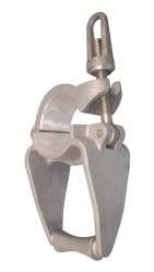
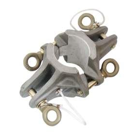


229 CONDUCTOR SUPPORT EQUIPMENT RITZ FERRAMENTAS G
RC400-0562
FLV00714-2
Catalog Reference Description Approx. Weight kg lb RM4805-15 1” fork-type wireholder with insulator 1.35 2.98 RM4805-17 1” fork-type wireholder without insulator 0.90 1.98 RE400-0008 1-1/2” fork-type wireholder without insulator 1.30 2.87 RE400-0009 1-1/2” fork-type wireholder with insulator 1.75 3.86 RC400-0331 Stirrup for brace (Ø 64 mm) 0.94 2.09 RM1728-5 64mm brace strap 1.50 3.31 FLV00714-2 Eye head without insulator 1.95 4.30 RC400-0562 Eye head with insulator 2.40 5.29
RM4805-17
RE400-0008
RC400-0331
RM1728-5


AUXILIARY CROSSARMS
The RH4862-6, RH4862-8, and RH4862-51 Auxiliary crossarms are used for operations to replace medium voltage overhead short span insulators or utility poles up to 15 kV phase/phase. It must be complemented with two saddles (FLV4740-5W) to install the auxiliary crossarm mast to the pole. Saddles must be purchased separately. It has a load capacity of 272 daN (600 lb), with four conductors in balance and 68 daN (150 lb), in each wireholder, at unbalanced condition.
230 CONDUCTOR SUPPORT EQUIPMENT RITZ FERRAMENTAS G
FLV05613-1
RM4805-16
Item Quant. Catalog Reference Description Approx. Weight kg lb 01 01 FLV21310-1 Ø 64 mm x 1.78 m Crossarm pole insulating length 5.10 11.24 02 01 FLV17928-1 Ø 64 mm x 1.35 m Mast pole insulating length 2.82 6.22 03 01 FLV05613-1 Auxiliary arm “T” 1.30 2.87 04 04 RM4805-16 C-type wireholder without insulator 1.08 2.38
RH4862-6 - AUXILIARY CROSSARMS
Item Quant Catalog Reference Description Approx. Weight kg lb 01 01 FLV21310-2 Ø 64 mm x 2.39 m Crossarm pole insulating length 5.10 11.24 02 01 FLV17928-1 Ø 64 mm x 1.35 m Mast pole insulating length 2.82 6.22 03 01 FLV05613-1 Auxiliary arm “T” 1.30 2.87 04 04 RM4805-16 C-type wireholder without insulator 1.08 2.38
RH4862-8 - AUXILIARY CROSSARMS
Item Quant. Catalog Reference Description Approx. Weight kg lb 01 01 FLV17928-2 Ø 64 mm x 2.83 m Mast pole insulating length 2.82 6.22 02 02 FLV03457-13 Ø 38 mm x 2.03 m Support insulating length 6.86 15.12 03 02 RM4741-3 Ø 64 mm clamp 1.00 2.20 04 01 RM1728-5 Ø 64 mm for Brace Strap 1.50 3.31 05 01 FLV05613-1 Auxiliary arm “T” 1.30 2.87 RH4862-51 RH4862-6
RH4862-51 - MAST & BRACES
| RH4863-10
Constructed with a special RITZGLAS® arm mast, composed of two support rods with a diameter of 64 mm, fixed to a saddle with tilt adjustment through 7 holes spaced at 15 degrees, for coupling to square or rectangular booms adjustable to dimensions ranging from 127 x 178 mm to 254x254mm of the aerial device or similar equipment.
The maximum balanced vertical load capacity on the three clips of the auxiliary crossarm is 454 daN (1000 lb). Sized to support a maximum unbalanced load of 90 daN (200 lb) on each of the clamp. Each roller lifting clamp (RC400-0268), used in this auxiliary crosshead, has a lateral load capacity of 45 daN (100 lb). Therefore, it is crucial that this auxiliary crosshead be attached only to equipment with a lifting capacity exceeding 907 daN (2000 lb).
Approximate weight: 48 kg (105.8 lb)

ACESSORY
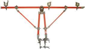


231 CONDUCTOR SUPPORT EQUIPMENT RITZ FERRAMENTAS G
RC400-0269
RC400-0268
RH4863-10
Catalog Reference Description Approx. Weight kg lb RC400-0268 Roller wireholder for mounting on the auxiliary crossarm of truck cranes or similar vehicle, 1-3/4” opening 1.90 4.19 RC400-0269 Roller wireholder for installation on auxiliary crossarm with insulator RM4805-7, 2” opening 2.50 5.51


EXTENSION ARM
They are designed for voltages up to 15 kV and are typically used for switching conductors or insulators. However, they can also be used at voltages up to 34.5 kV provided insulators (RM4805-7) are installed in the wireholders.
It is a tool attached under the crossarm so that approximately 3/4 of its length exceeds that crossarm to allow the conductors to be transposed into their wireholders.

AUXILIARY CROSSARM SUPPORT FOR AERIAL DEVICE
It is designed for fast and safe operation, with the aid of an aerial device, to replace crossarms, insulators or poles in short spans of live overhead networks up to 34.5kV
It has clamps for fitting and adjusting auxiliary Ø 64mm pipe crossarms
It is also adaptable in various square or rectangular sections of aerial device.
Its installation and removal is simple and the tool can be easily stored and transported as it is a compact and lightweight solution for the type of operation it is intended for.
* Attention should be paid to air basket capacity and restricted to it if it is lower
232 CONDUCTOR SUPPORT EQUIPMENT RITZ FERRAMENTAS G
Catalog Reference Ø (mm) Insulating Length (m) Number of Wireholders per Product For Crossarm with Maximum Dimension (mm) Maximum Vertical Capacity per Wireholder Approx. Weight daN lb kg lb RH4800-60 64 1.43 1 95 x 120 68 150 5.80 12.79 RH4800-72 64 1.74 2 95 x 120 68 150 7.40 16.31 RT403-2417 64 1.74 2 95 x 120 e 152 x 152 68 150 6.30 13.90 RC400-1310 76 1.74 2 95 x 120 e 152 x 152 136 230 10.90 24.00 Catalog Reference Rated load capacity (kgf/lbf)* Man basket minimum section (mm) Max. perimeter of man basket section (mm) Approx. Weight kg lb FLV30045-1 280 / 617 128 width 183 height 910 8.70 19.20
TEMPORARY CONDUCTOR SUPPORT
| RC400-0517
The conductor support can be attached to crossarms, with sizes 82 x 102 mm to 152 x 152 mm. The C-shaped clamp as well as the wireholder is made of heat-treated aluminum alloy and fixed to the RITZGLAS® tube. It can be installed with the hot stick.
| FLV30058-1
The conductor support pole (used for lifting conductor cables through its upper head by its lifting wireholder) is adaptable to metal post straps through support with a lower blade.
| | RC400-1509
RH4809-W
They are used to support energized distribution conductors during pole replacement, repair, or pin or top insulators replacement.
They are equipped with a pole chain stretcher, over Ø 356 mm, and lifting wireholders for conductors up to Ø 25.4 mm (for RC400-1509 with two units and RH4809-W with one unit).
When using temporary support with voltages greater than 15 kV or when supporting energized conductors in the rain (or chance to rain), mounting insulators (RM4805-7) is recommended as additional protection.
| | RT400-1939
RT400-1940
These two temporary support models have the same functions as RC400-1509 and RH4809-W. The difference is the pole mounting system, which in this case coma nylon tie tensioner. (RT400-2007)
The same recommendations for using the insulator (RM4805-7) and the rated workload also prevail for these two models.
| RT400-2272
The insulator change support is designed for special applications for distribution insulator change, whose conductors are angled
Used in combination with a nylon strap hoist, it sustains the conductor under mechanical stress during the insulator change and assists the conductor back to its original location.
With this tool there is no need to use round covers or blankets on the pole to insulate the hoist.
To insulate the hoist with a nylon tie, two insulating rods (RC400-1175 or RC400-2399 or RC400-2400) are used, connecting their hooks to the wire grips and their eyes to the hooks of the hoist.
This equipment was made with Ø 64 mm RITZGLAS® tube, insulating length 0.15 m and working length 0.40 m.
| RT400-2007
It is coupled to the pole using the nylon tie tensioner (RT400-2007).

RC400-0517

FLV30058-1

RC400-1509

RH4809-W

RT400-1940

RT400-2272

RT400-2007
233 CONDUCTOR SUPPORT EQUIPMENT RITZ FERRAMENTAS G
TYPICAL APPLICATIONS

In this arrangement, the insulator change bracket is installed on the opposite side of the conductor and is used when a short distance from the conductor in relation to the post is required
TEMPORARY SUPPORT
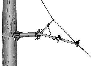
In this other arrangement, the insulator change bracket is installed on the conductor side in order to obtain a greater distance from it.
234 CONDUCTOR SUPPORT EQUIPMENT RITZ FERRAMENTAS G
Catalog Reference Description Rated Work Capacity Approx. Weight daN lb kg lb RC400-0517 Conductor bracket, with crossarm mounting and Ø 32 mm x 200 mm insulating length 68 150 2.20 4.85 FLV30058-1 Conductor support pole, adaptable to the post through the support with a blade and Ø 38 mm x 250 mm insulating length 38 83,78 1.96 4.32 RC400-1509 Conductor's bracket, with pole mounting through chain stretcher, mounted to Ø 64 mm x 1.11 m insulating length RITZGLAS® tube, with wireholders 68 150 7.70 16.98 RH4809-W Conductor's bracket, with pole mounting through chain stretcher mounted on Ø 64 mm RITZGLAS® tube, with 1 wireholder. Spacing between clamp and pole mounting: 0.76 m 68 150 6.30 13.89 RT400-1939 Pole-mounted conductor's support via nylon tie-pole, mounted on Ø 64 mm x 1.11 m insulating length RITZGLAS® tube, with 2 wireholders 68 150 8.10 17.85 RT400-1940 Conductor bracket, with pole mounting using a nylon tie tensioner, mounted on a Ø 64 mm RITZGLAS® tube, with 1 wireholder. Spacing between clamp and pole mounting: 0 76 m 68 150 6.40 14.00 RT400-2272 Support for insulator change, with pole mounting system through a nylon tie tensioner Insulating length: 0.15 m Work length: 0.40 m 907 2000 5.90 13.00 RT400-2007 1.20 m nylon tensioner for replacement of insulator change support RT400-2272 907 2000 1.40 3.00
Nylon Strap Hoist Insulating Pole with Hoist Insulator Change Support Insulating Pole with Hoist Insulator Change Support Nylon Strap Hoist
HOT STICK TENSION PULLER
It is intended for strain and support of energized conductors The hot tension puller stick can also be used during insulator replacement, conductor splicing work or for a number of works on energized installations.
Its basic construction (combining Ø 38 mm RITZGLAS® tube and single body strain device) makes it a versatile and complete tool.
It has non-rotating forged steel hooks and safety lock and eyebolts, which llow the quick and easy installation of the insulated strain jack manually or by means of an insulating pole.
The safety locks turn 135° to the right and left from the closed position.
The drive lever has an eye for insertion of the stick and allows operation from distance.


235 CONDUCTOR SUPPORT EQUIPMENT RITZ FERRAMENTAS G Insulating Length Work Length Catalog Reference Voltage (kV) Max Load Capacity Work Length Between Hooks (m) Maximum Tool Displacement (m) Insulating Length (m) Approx. Weight daN lb kg lb RC400-0574 34.5 1814 4000 Minimum: 1.64 Maximum: 1.94 0.30 0.79 6.40 14.11 RC400-0575 69.0 Minimum: 1.84 Maximum: 2.14 0.99 6.50 14.33
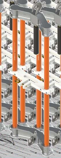
SYMMETRICAL TENSION PULLER
Fitted with a hook, the Symmetrical Tension Puller is a removable suspension device used to take off the mechanical tension of conductors and used to remove 254mm insulator chains. Used in overhead networks in the distance method.
Symmetrical Tension Puller made of Ø32mm RITZGLAS® tube, aluminum hook jaw, central support in white nylon and steel fixing hooks
STRAIN LINK STICK
It is used in angle anchor structures as insulation between blocks and wire grips. Large-span conductor loads and “H” structures sometimes exceed the safe capacities for the wire tong. To supplement the wire tong, attach the strain link stick to the conductor This stick is also used to support the center conductor in “H” type structures when changing insulators or crossarms
Constructed with RITZGLAS® insulating tube and aluminum alloy fittings, for better mechanical strength and lightness ratio, the swivel eye has bearings for smooth and perfect rotation. The jaw edges of this tool are rounded to prevent damage to conductors.
To meet a higher demand for tasks that require loads or varieties of wire size, this tool is built in four head sizes and variations in pipe lengths.


Insulating Length
236 CONDUCTOR SUPPORT EQUIPMENT RITZ FERRAMENTAS G
Catalog Reference Insulating Length (m) Working Length (m) Rated Work Capacity Approx. Weight Minimum Maximum daN lb kg lb FLV19769-1 0.90 1.13 1.35 1700 3750 7.00 15.43
237 CONDUCTOR SUPPORT EQUIPMENT RITZ FERRAMENTAS G Insulating Length
Catalog Reference Dimensions Jaw Opening (mm) Rated Work Capacity Storage (optional) Approx. Weight Ø (mm) Insulating Length (m) Minimum Maximum daN lb kg lb RC400-0814 32 1.70 5.60 19.00 1588 3500 FLV18339-2 2.30 5.07 RC400-0815 32 2.30 5.60 19.00 1588 3500 FLV18339-3 2.60 5.73 RC400-0816 32 2.90 5.60 19.00 1588 3500 FLV18339-4 2.90 6.39 RC400-0817 32 3.60 5.60 19.00 1588 3500 FLV18339-5 3.20 7.05 RC400-0818 32 4.20 5.60 19.00 1588 3500 FLV18339-14 3.60 7.94 RH4715-1 32 0.50 5.60 19.00 1588 3500 FLV18339-15 1.70 3.75 RH4715-2 32 1.10 5.60 19.00 1588 3500 FLV18339-1 2.00 4.41 RH4716-1 38 0.45 11.20 27.00 2948 6500 FLV18339-15 2.90 6.39 RH4716-2 38 1.05 11.20 27.00 2948 6500 FLV18339-1 3.30 7.28 RH4716-3 38 1.65 11.20 27.00 2948 6500 FLV18339-2 3.70 8.16 RH4716-4 38 2.25 11.20 27.00 2948 6500 FLV18339-3 4.15 9.15 RH4716-5 38 2.85 11.20 27.00 2948 6500 FLV18339-4 4.60 10.14 RH4716-6 38 3.55 11.20 27.00 2948 6500 FLV18339-5 5.00 11.02 RH4717 38 1.05 18.30 38.00 2948 6500 FLV18339-12 3.40 7.50 RH4717-1 38 1.65 18.30 38.00 2948 6500 FLV18339-13 3.80 8.38 RH4718 38 1.05 25.40 63.50 2948 6500 FLV18339-12 4.30 9.48 RH4718-1 38 1.65 25.40 63.50 2948 6500 FLV18339-13 4.70 10.36 RH4718-2 38 2.25 25.40 63.50 2948 6500 FLV18339-4 5.10 11.24 RH4718-3 38 2.85 25.40 63.50 2948 6500 FLV18339-4 5.60 12.35 RH4718-4 38 3.55 25.40 63.50 2948 6500 FLV18339-14 6.00 13.23
STRAIN LINK STICK
SPIRAL LINK STICK
It is used in situations where the work areas in the structure have reduced spaces for the electrician to install the strain link stick safely. An eye near the spiral hook allows the electrician to install the spiral link pole into the conductor with the aid of a hot stick.
It is made with a RITZGLAS® tube, a special, hot-dip galvanized, sturdy, spiralshaped steel hook suitable for the workloads required for conductors with sizes up to 1510.5 kcmil ACSR (approx. Ø 38 mm) and aluminum alloy heads.
The swivel eye also has bearing for smooth rotation.


238 CONDUCTOR SUPPORT EQUIPMENT RITZ FERRAMENTAS G Insulating Length
Catalog Reference Dimensions Rated Work Capacity Storage (optional) Approx. Weight Ø (mm) Insulating Length (m) daN lb kg lb RH4722 32 0.29 1588 3500 FLV18339-15 1.00 2.20 RC400-0812 0.96 FLV18339-12 2.30 5.07 RC400-0813 1.57 FLV18339-2 2.60 5.70
ROLLER LINK STICK
It is used to move and keep the energized conductor in the middle of the span in order to obtain more work space when changing the pole
When placed on the conductor, it is supported by the pole roller for easy movement along the line with the aid of a rope or block attached to the eye, pulled by the electrician from the ground.
The roller head of this tool allows a maximum conductor size of up to 605 kcmil ACSR (Ø 24 mm approx.).
Constructed with RITZGLAS® tube, its bronze alloy hook and roller is installed on a threaded pin, responsible for its rotation for closing and opening the jaw, where the conductor is secured. It has a heat-treated aluminum alloy heads and a forged steel swivel ring with rolling for smooth rotation.


239 CONDUCTOR SUPPORT EQUIPMENT RITZ FERRAMENTAS G Catalog Reference Dimensions Rated Work Capacity Storage (optional) Approx. Weight Ø (mm) Insulating Length (m) daN lb kg lb RH4714-4 32 1.13 454 1000 FLV18339-12 2.48 5.47 RH4714-6 1.74 FLV18339-13 2.80 6.17
Insulating Length
STRAIN POLE
CLEVIS-EYE / CLEVIS-CLEVIS
They are designed for use in single or multiple suspension or anchor strings. Also used in V-strings, directly coupled to the yoke plate hole in order to relieve the load of the two strings simultaneously
Built with RITZGLAS® tubes, they feature non-swiveling aluminum alloy eye heads and adapt to a wide range of aluminum sheet yoke shapes through the bronze alloy clevis heads.
CLEVIS-EYE STRAIN POLE


CLEVIS-CLEVIS STRAIN POLE

240 CONDUCTOR SUPPORT EQUIPMENT RITZ FERRAMENTAS G Insulating Length
Catalog Reference Description Ø (mm) Insulating Length (m) Rated Work Capacity Approx. Weight daN lb kg lb RC400-0612 With bronze alloy clevis head, 27 mm internal opening and locking eye pin 51 2.52 2948 6500 6.10 13.45 RC400-0613 With bronze alloy clevis head, 27 mm internal opening and locking eye pin 3.05 6.70 14.77
Catalog Reference Description Ø (mm) Insulating Length (m) Rated Work Capacity Approx. Weight daN lb kg lb FLV29023-1 With bronze alloy clevis head, 27 mm internal opening and locking eye pin 51 3.79 5443 12000 9.30 20.5 FLV29023-2 With bronze alloy clevis head, 27 mm internal opening and locking eye pin 4.09 9.70 21.40 FLV29023-3 With bronze alloy clevis head, 27 mm internal opening and locking eye pin 3.94 9.50 20.90 FLV29023-4 With bronze alloy clevis head, 27 mm internal opening and locking eye pin 1.84 6.90 15.20 FLV29023-5 With bronze alloy clevis head, 27 mm internal opening and locking eye pin. 4.29 9.90 21.80 Insulating Length
ADJUSTABLE STRAIN POLES
It is made with Ø 51 mm RITZGLAS® tube and has 6 stainless steel cross-pins (5 working and 1 locking), at 152 mm intervals to support the adjustable pole clamp on the live end.
The 5-pin arrangement allows yoke displacement to a maximum length of 608 mm.
The hot-end yokes for suspension or anchor insulator strings are coupled to the Strain Poles through their adjustable pole clamps. The pole clamps can be adjusted manually or with a Hot Stick. The adjustable hook assembly can be used directly on the Strain Pole to lift the conductor, where yoke use is not required
On the de-energized side, a special 305 mm long steel bolt allows a uniform straining of the assembly through ratchet wrenches and trunnions
It also has strain jacks of different lengths and the adjustable pole clamp or adjustable hook assembly can be purchased separately or as spare parts
Trunnions and ratchet wrench can also be purchased separately.
This tool is essential in a wide variety of tasks when servicing high voltage and extra high voltage transmission lines. Adjustable strain poles can be used with adjustable pole clamp (RE401-0138) or adjustable hook assembly (RM4724-1).
COMPOSITION OF THE SET
Adjustable strain poles (RC401-2144 to RC401-2149 series) are supplied with the following components:
- 01 Ø 51 mm Strain Pole with clevis head;
- 01 Adjustable pole clamp RE401-0138;
- 01 Strain Jack RE401-1998 (305 mm length);
- 01 Strain Jack Locking Pin RE401-1510;
- 01 Cotter Pin FLV11384-1;


241 CONDUCTOR SUPPORT EQUIPMENT RITZ FERRAMENTAS G Insulating Length Total Length Clevis RE401-1510 RE401-1998 305 mm
ADJUSTABLE STRAIN POLES
Rated Work Capacity: 3402 daN (7500 lb).
ACCESSORIES
242 CONDUCTOR SUPPORT EQUIPMENT RITZ FERRAMENTAS G
Catalog Reference Maximum Use Voltage (kV) Insulating Length (m) Total Length (m) Storage (optional) Approx. Weight kg lb RC401-2144 72.5 0.91 2.29 FLV18339-13 8.50 18.74 RC401-2145 169 1.22 2.60 FLV18339-3 8.90 19.62 RC401-2146 242 1.60 2.98 FLV18339-4 9.30 20.50 RC401-2147 302 2.13 3.51 FLV18339-5 10.00 22.05 RC401-2215 362 2.60 3.98 FLV18339-14 11.30 24.91 RC401-2148 552 3.43 4.81 FLV18339-16 11.50 25.35 RC401-2149 765 4.57 5.95 FLV18339-17 13.00 28.66
Catalog Reference Description Approx. Weight kg lb RE401-0138 Adjustable pole clamp Ø 51 mm 0.70 1.54 RE401-1998 Strain Jack 305 mm long 1.30 2.87 RV401-0157 Strain Jack 610 mm long 1.80 3.97 RV401-0158 Strain Jack 915 mm long 2.30 5.07 RE401-1510 Steel Pin to lock clevis bolt 0.30 0.66 Insulating Length Total Length
SECTIONAL STRAIN POLE (WITH SPLICE)
| RC401-0758
Designed to withstand the mechanical strain of conductor cables while maintaining suspension or anchor insulator strings where their lengths differ from conventional standards.
This pole consists of three parts: hot-end pole (energized), cold-end pole (de-energized), and the fiberglass splice, which is the central tube responsible for joining the live and cold end poles.
Constructed with Ø 51 mm RITZGLAS® tube, each has a clevis-type bronze alloy head for connection to the yokes. The fiberglass splice is manufactured by a special process, with Ø 76 mm exterior reinforced fiberglass, and has equidistant holes every 100 mm, making it possible to assemble the hot-end and cold-end poles, within pre-established lengths
The poles also allow combinations with strain jacks in lengths 305, 610 and 915 mm for additional gain in overall assembly length.
Hot or cold-end poles, fiberglass splice, strain jack, or cotter pins can be purchased separately as spare parts
Length: minimum 3.15 m | maximum 3.75 m
Rated Work Capacity: 4536 daN (10000 lb)
Approx. Weight.: 13.90 kg (30.64 lb)
NOTE
Although the splicing fiberglass splice is manufactured to a standard length of 1.12 m, dead and hot-end poles can be purchased with special lengths to suit the types and strains of each company's networks. For such supplies, which will depend on the arrangements of the strings, their design must be sent to our engineering department for technical feasibility analysis.
COMPOSITION OF THE SET
- 01 RITZGLAS® hot-end pole, with clevis-type bronze alloy head and steel pin and cotter pin.
- 01 RITZGLAS® cold-end pole, with clevis-type bronze alloy head and steel pin and cotter pin.
- 01 fiberglass splice, 1.12 m long, and two sets of steel pins and cotter pins.

243 CONDUCTOR SUPPORT EQUIPMENT RITZ FERRAMENTAS G 1,44 m 1,44 m 0,27 m 100 mm Ø 75 mm Ø 51 mm
LIGHT-WEIGHT STRAIN CARRIER
| FLV17450-1
It is designed for Grosbeak conductors, up to 636 MCM (Ø 25.15 mm), for changes of single strings of 69 to 145 kV anchorage and 110 to 145 kV suspension on hot lines
The excellent mechanical characteristics of the RITZGLAS® tube allow the strain pole diameter to be reduced to just 32 mm (1-1/4”), with consequent proportional reduction of metal parts, making it a light and practical set for easy handling and transport.
Metal tools that work on the de-energized side are used for both anchoring and suspension, providing versatility to the assembly and making it more economical and attractive in terms of cost effectiveness.
Rated Work Capacity: 2948 daN (6500 lb)
Used

Used in the maintenance of suspension insulator

244 CONDUCTOR SUPPORT EQUIPMENT RITZ FERRAMENTAS G
in the maintenance of anchoring insulator
COMPOSITION OF THE ANCHOR SET
COMPOSITION OF THE SUSPENSION SET
245 CONDUCTOR SUPPORT EQUIPMENT RITZ FERRAMENTAS G
Catalog Reference Description Quantity Approx. Weight kg lb FLV13352-1 Cold-end yoke with 1400 mm string 01 8.10 17.86 RE401-1998 305 mm long strain jacks with 02 1.30 2.87 RE401-2068 Small trunnion 02 0.83 1.83 FLV13780-1 Ø 32 mm RITZGLAS® Insulating Strain Poles, 2.70 m total length, with cast aluminum clevis for strain jack coupling and 10 pins, 152 mm spacing for hot-end yoke coupling 02 4.10 9.04 FLV12192-1 Cast aluminum alloy hot-end yoke with 2 pairs of ACSR cable clamps, minimum 2 AWG (Ø 6.6 mm) to maximum 636 MCM (Ø 25 mm) 01 5.80 12.79 Total 20.13 44.39
Catalog Reference Description Quantity Approx. Weight kg lb FLV13352-1 Cold-end yoke with 1400 mm string 01 8.10 17.86 RE401-1998 305 mm long strain jacks with 02 1.30 2.87 RE401-2068 Small trunnion 02 0.83 1.83 FLV13130-1 Ø 32 mm RITZGLAS® Insulating Strain Poles, total length 1.46 m, with die-cast aluminum clevis at both ends 02 2.60 5.73 FLV13356-1 Cast aluminum alloy support for coupling to the tower crossarm, hook string, and safety lock 01 3.40 7.50 FLV13006-1 Spiral Hook Parts of special heat treated steel, 695 mm length with eye for coupling to the clevis-clevis strain pole 02 2.30 5.07 FLV13006-2 Spiral Hook Parts of special heat treated steel, 615 mm length with eye for coupling to the clevis-clevis strain pole 02 2.00 4.41 FLV13006-3 Spiral Hook Parts of special heat treated steel, 555 mm length with eye for coupling to the clevis-clevis strain pole 02 1.80 3.97 Total 22.30 49.16


APPLICATION OF EACH TOOL
1. FLV13352-1 (cold-end yoke)
It is applied to anchor and suspension strings
In anchor strings, it is coupled to the tower crossarm, with the string. In the suspension string it is coupled to the tower crossarm with the aid of the support (FLV13356-1.
2. FLV13356-1 (support)
It is supported and mounted to the end of the tower crossarm to support and couple the cold-end yoke (FLV13352-1) in suspension string changes
3. FLV12192-1 (hot-end yoke)
It couples directly to the cable, eliminating the use of wire grip when replacing the anchor string
4. FLV13780-1 (insulating strain pole)
The cold-end yoke is attached to the strain jack The 10 pairs of hot-end pins support and couple the yoke without requiring an adjustment pole clamp when changing the insulator string in the anchor structure.
5. FLV13130-1 (insulating strain pole)
With the Strain Jack (RE401-1998) coupling at one end and the Spiral Hook (FLV13006-1, FLV13006-2, FLV13006-3) at the other end, this tool is used to support the cable in suspension string exchange
STRAIN POLE


NOTE
Poles in other lengths can be purchased on request
246 CONDUCTOR SUPPORT EQUIPMENT RITZ FERRAMENTAS G
Catalog Reference Insulating Length (m) Working Length (m) Minimum Maximum FLV13780-1 1.09 1.16 2.53 FLV13130-1 1.22 1.45 1.45
FLV12192-1
FLV13352-1
FLV13356-1
FLV13130-1
FLV13780-1
6. RE401-1998 (strain jack)
Attachable to the strain pole (FLV13780-1) by the eye yoke system and to the dead yoke (FLV13352-1) through the small trunnion (RE401-2068).
NOTE
Bolts in other lengths can be purchased on request.
7. RE401-2068 (small trunnion)
Threaded into the strain jack (RE401-1998) with the aid of the ratchet wrench (RM1948-3) to tension the conductor, transferring the string load to the strain set.
8. FLV13006-1 / FLV13006-2 / FLV13006-3 (spiral hook)
Coupled to the Strain Pole (FLV13130-1), the spiral hook secures the conductor to support it in the suspension string change. Each of the 3 hook sizes is used according to the length of the hot-end hardware of the insulator string.
9. RM1948-3 (ratchet wrench)
Although this tool is not included in the strain set, we recommend purchasing it for single trunnion application (RE401-2068).
10. FLV19286-1 (bag)
Used for storage and transporting of strain pole FLV13780-1.
11. FLV19286-2 (bag)
Used for storage and transporting of strain pole FLV13130-1.
12. ATR09962-1 (multi-purpose handbag)
Used for storage and transport of the other components of the set.


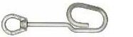


247 CONDUCTOR SUPPORT EQUIPMENT RITZ FERRAMENTAS G
RE401-1998
RE401-2068
FLV13006-1
FLV13006-2
FLV13006-3
RM1948-3
DISTRIBUTION STRAIN CARRIER

The RC401-0411 and RC401-0410 Distribution Double Strain Carriers relieves the tension of the anchor insulator string to allow it to be removed from the energized line. It has a yoke on the hot-end equipped with jaws that are mounted to the conductor by compression, tightening each time the strain load increases


These jaws are designed to be mounted to conductors with Ø 7.40 to 20.50 mm (2 to 397.5 ACSR). The other end of the assembly is equipped with yoke and hook string for anchoring to the structure. Special 305 mm long steel bolts with small trunnion allow for even strain of the assembly.
COMPOSITION OF THE SET
Distribution Double Strain Carriers are supplied with the following components:
- 02 Ø 32 mm RITZGLAS® Poles, for adjustments to the yoke through the 05 steel pins in each pole and adjusting every 152 mm;
- 01 Yoke FLV12192-1 for hot-end mounting;
- 01 Yoke FLV12239-1 for anchoring the assembly to the structure through the chain (RM1942) accompanying the assembly;
- 02 Strain Jacks RE401-1998 (305 mm);
- 02 Small trunnion RE401-2068.
Strain Jacks, trunnions, and yokes can be purchased separately as spare parts
248 CONDUCTOR SUPPORT EQUIPMENT RITZ FERRAMENTAS G
152 mm 462 mm 305 mm Strain Jack Ø 32
Yoke (hot end) Yoke (cold end) Small Trunnion Steel pin Insulating Length Minimum working length Maximum working length
mm
FLV12192-1
FLV12239-1 RM1942
DISTRIBUTION STRAIN CARRIER
Catalog Reference Strain Pole
Rated working capacity is 2948 daN (6500 lb) for distribution strings between 69 and 145 kV.
STRAIN POLE
249 CONDUCTOR SUPPORT EQUIPMENT RITZ FERRAMENTAS G
Working Length (m) Approx. Weight Minimum Maximum kg lb RC401-0411 FLV12240-2 1.10 1.70 26.70 58.86 RC401-0410 FLV12240-1 1.70 2.32 27.30 60.19
Catalog Reference Insulating Length (m) Overall Length (m) Approx. Weight kg lb FLV12240-2 0.97 1.83 6.20 13.67 FLV12240-1 1.59 2.44 5.40 11.90
TWO-POLE STRAIN CARRIER

The Two-pole Strain Carrier (RC401-2174 to RC401-2179 series) relieves the mechanical strain of the insulator string so it can be removed from the energized line for to be changed, either in single or multi-insulator string according to the string arrangement hardware
Strain Poles are used with adjustable pole clamps and yokes, with trunnions and strain jacks.
Through the adjustable pole clamp the energized side suspension or anchor yokes are coupled to the Strain Poles. The pole clamps can be adjusted manually or with a Hot Stick.
The energized side yoke includes a steel hook.
The yokes are constructed of rolled aluminum sheets and include a hook string for anchoring to the structure.


Strain Jacks, adjustable pole clamps, trunnions or yokes can be purchased separately as replacement parts.
COMPOSITION OF THE ASSEMBLY
The above mentioned Double Strain Carriers are supplied with the following components:
- 02 Ø 51 mm RITZGLAS® Strain Poles, with clevis heads and pins and cotter pins;
- 01 Yoke RC401-1721 for anchoring to the structure (including its respective string Rm1942);
- 01 Yoke RC401-1720 for hot-end mounting;
- 02 strain jacks RE401-1998 (305 mm);
- 02 Adjustable pole clamp RE401-0138;
- 02 Small Trunnions RE401-2068;
- 01 Socket for Yoke RC401-1720
250 CONDUCTOR SUPPORT EQUIPMENT RITZ FERRAMENTAS G
Strain Jack 305 mm 660 mm Ø 51 mm 152 mm Yoke (hot end) Yoke (cold end) Small Trunnion Maximum working length Minimum working length Steel pin RC401-1720 RM1942 RC401-1721
TWO-POLE STRAIN CARRIER
The rated working capacity is: 6804 daN (15000 lb)
251 CONDUCTOR SUPPORT EQUIPMENT RITZ FERRAMENTAS G
Catalog Reference Strain Pole Working Length (m) Approx. Weight Minimum Maximum kg lb RC401-2174 RC401-2144 1.09 1.88 33.70 74.30 RC401-2175 RC401-2145 1.40 2.19 34.00 74.96 RC401-2176 RC401-2146 1.78 2.57 34.50 76.06 RC401-2177 RC401-2147 2.32 3.10 35.20 77.60 RC401-2216 RC401-2215 2.78 3.57 36.20 79.81 RC401-2178 RC401-2148 3.61 4.40 36.70 80.91 RC401-2179 RC401-2149 4.75 5.54 38.20 84.22


AUXILIARY STRAIN CARRIER
The Auxiliary Strain Carrier is a lightweight, portable tool designed for quick replacement of damaged insulators in de-energized suspension strings, especially when the number of damaged insulators does not justify the removal and lowering of the entire string for ground replacement.
SAFETY PROCEDURE
When changing insulators in the de-energized suspension chains, handling the Auxiliary Strain Carrier requires special attention about its installation in the network, in order to avoid accidents
1. This tool is only used in de-energized networks
2. Prior to the installation of the auxiliary strain pole, the electrician will first need to install a complete strain set (yoke + strain pole) and suitable for the insulator string in order to relieve the mechanical strain of the string and allow insulator decoupling.
3. After that, the nut and the auxiliary strain pole will be mounted on the insulator directly above the one to be replaced (changing one insulator at a time).
4. When coupling, make sure that the insulator cap is resting only on the upper base of the yoke when using model FLV11537-1, or on the upper base of the nutswhen using models FLV30577.
| FLV11537-1
It has two Yokes made of cast aluminum alloy, in addition to two trunnions and two tensioning screws
Rated Work Capacity: 600 daN (1322 lb)
Approx. Weight: 8.15 kg (17.95 lb)
252 CONDUCTOR SUPPORT EQUIPMENT RITZ FERRAMENTAS G
350 mm 432 mm 695 mm
FLV11537-1
It has two Yokes that are coupled to the insulator cap with the help of shoes manufactured according to the insulator model (purchased separately), made of cast aluminum alloy, in addition to two trunnions and two tensioning screws.
Rated Work Capacity: 600 daN (1322 lb)
Approx. Weight: 10.40 kg (22,92 lb) 10.20 kg (22.48 lb)
(FL V30577-3) 1270 mm (FL V30577-4) 1070 mm
443 mm 443 mm
NOTE
Removable shoes (purchased separately) are changed to fit different types of insulators When the models available in this catalog do not meet the insulator specifications, the insulator drawing must be made available for evaluation by our engineering department for the development of the appropriate shoes. |
SHOES


253 CONDUCTOR SUPPORT EQUIPMENT RITZ FERRAMENTAS G
|
FLV30577-3 FLV30577-4
Catalog Reference Isolator Model Diameter (mm) Pitch (mm) FLV30669-1 F300 PU C 195 300 195 FLV31349-1 ST254 V12 ACCBG 254 146 FLV31351-1 VIFOSA M98 160 KN 280 170
FLV30577
Shoes
ACCESSORIES FOR STRAIN CARRIERS
Strain Jack
The tongue type strain jacks are used in coupling to the strain poles as an adjustment tool in insulator string straining They are coupled through the eye of the strain pole through the head in one of its ends
Rated Work Capacity: 4536 daN (10000 lb)
| RE401-1998
Total length 305 mm
Approx. Weight: 1.30 kg (2.87 lb)
| RV401-0157
Total length 610 mm
Approx. Weight: 1.80 kg (3.97 lb)
| RV401-0158
Total length 915 mm
Approx. Weight: 2.30 kg (5.07 lb)
Clevis Type Strain Jack
Clevis type strain jacks are used in connection with the clevis-eye strain poles (RH1949-113 / RC400-0612 and RC400-0613) as an adjustment tool for straining insulator strings. They are coupled through the eye of the strain pole through the head in one of its ends.
Rated Work Capacity: 4536 daN (10000 lb)
| RH4785-1
Total length 305 mm
Approx. Weight: 1.40 kg (3.09 lb)
| RH4785-2
Total length 457 mm
Approx. Weight: 1.70 kg (3.75 lb)

RE401-1510
R059738

| RH4785-3
Total length 610 mm
Approx. Weight: 2.00 kg (4.41 lb)
| RT400-0025
Total length 915 mm
Approx. Weight: 2.50 kg (5.51 lb)
Eye Pin and Click Safety Cotter Pin
FoFor locking the strain jack in the strain pole clevis
| | R059738
RE401-1510
Eye Pin Click safety cotter pin
Approx. Weight: 0.30 kg (0.66 lb)
Approx. Weight: 0.05 kg (0.11 lb)
254 CONDUCTOR SUPPORT EQUIPMENT RITZ FERRAMENTAS G
Trunnion
Specially designed for coupling the yokes on the strain poles They are made of bronze alloy and have bearings to make them light during their rotation on the strain jacks.
Rated Work Capacity: 4536 daN (10000 lb)
| RE401-2068
Simple Trunnion
Approx. Weight: 0.83 kg (1.83 lb)
| RE401-2066
Large Trunnion
Approx. Weight: 1.40 kg (3.09 lb)
Trunnion Gauge
| FLV17755-1
Made of steel, this gauge is an essential tool for periodically checking the trunnion threads to check for wear on the trunnion threads
When testing, if the trunnion allows its insertion, even partially, a thread wear of more than 0.5 mm will be identified, thus ensuring that it is unfit for use.
Approx. Weight: 0.37 kg (0.82 lb)
Safety steel nut for trunnion support
| FLV10460-1
The installation of the locknut is recommended for shortly after placing the trunnions on the strain jacks as additional safety during the strain operation, and acts as a support in the trunnions.
Approx. Weight: 0.11 kg (0.24 lb)
Adjustable Pole Clamp
| RE401-0138
Used for coupling the yokes to the strain pole (Ø 51 mm) on the hot end, where allows manually or via stick the adjustment and displacement of the pole clamp for better positioning on the Strain Pole’s steel pins.
Rated Work Capacity: 3402 daN 7500 lb)
Approx. Weight: 0.70 kg (1.54 lb)
Ratchet wrench
Used for force application when tightening and loosening hex nuts and trunnions in the maintenance of transmission lines. It has system that allows changing the direction of tightening or loosening during application.


| | FLV16054-1
RM1948-3
Total length 255 mm
Approx. Weight: 1.05 kg (2.32 lb)
Total length 376 mm
Approx. Weight: 1.20 kg (2.65 lb)


255 CONDUCTOR SUPPORT EQUIPMENT RITZ FERRAMENTAS G
FLV10460-1
RE401-0138
RM1948-3
FLV16054-1
RE401-2066
RE401-2068
FLV17755-1
HEAVY-DUTY SUSPENSION LINK STICK
It is designed for suspension of Ø 25 to 64 mm conductors and can be used with a number of lifting devices at the structure end.
Constructed with a Ø 38 mm RITZGLAS® tube, one end is fitted with a cast aluminum alloy main head with rubber coating to prevent damage to the conductor
At the other end it is fitted with an aluminum alloy head and non-swivel eye.


256 CONDUCTOR SUPPORT EQUIPMENT RITZ FERRAMENTAS G Catalog Reference Conductor Heads (Ø) Dimensions Rated Work Capacity Approx. Weight Ø (mm) Insulating Length (m) daN lb kg lb RH4719-84 3/4” to 1-3/4” 38 2.00 2948 6500 5.00 11.02 RH4719-96 2.31 5.30 11.68 RH4719-114 2.61 5.70 12.55 RH4720-84 1” to 2-1/2” 38 2.00 2948 6500 5.20 11.45 RH4720-96 2.31 5.50 12.10 RH4720-114 2.61 5.90 13.00
Insulating Length
ADJUSTABLE HOOK ASSEMBLY
This tool can be used with strain poles RC401-2144 to RC401-2149 and is a simple and fast method of lightening the mechanical load on a suspension string.
It has a circular shape with a movable jaw that is adjusted to the conductor through the eye bolt, which allows a Ø 28 to 64 mm (RM4724-1) and Ø 14 to 36 mm (FLV16193-1) coupling approximately.
This movable jaw is self-aligning with the conductor as it has a 45° left or right vertical variation.
The hook is adjusted to the steel pole pins every 152 mm.

SUSPENSION POLE WITH ADJUSTABLE HOOK
The position of the conductor hook can be adjusted along the pole according to the length of the insulator string. Tightening the nuts on each side of the adjustable hook clamp ensures their secure connection to the pole.
The hook has wide jaws with rounded corners to prevent crushing or cuts in the conductor.
The swivel eye rotates freely and enables the use of hoists, ropes, or screws. The strain hook and base terminal are made of sturdy, heat-treated aluminum alloy.


257 CONDUCTOR SUPPORT EQUIPMENT RITZ FERRAMENTAS G Catalog Reference Description Approx. Weight kg lb RM4724-1 Adjustable Hook Assembly (Ø 28 to 64 mm) 2.60 5.73 FLV16193-1 Adjustable Hook Assembly (Ø 14 to 36 mm) 2.55 5.62 Rated Work Capacity: 1688 daN (3720 lb)
Catalog Reference Ø (mm) Total Length (m) Insulating Length (m) Rated Work Capacity Approx. Weight daN lb kg lb RH4710-4 64 2.00 1.55 1134 2500 6.50 14.33
Insulating Length
RM4724-1
YOKE

660mm
RC401-1720
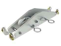
535mm
RM2946-1

They are tools for coupling strain poles to yoke plates, extension links or other support in structures to relieve the mechanical stress of a single or multiple insulator string at anchor or suspension in order to replace damaged insulators.
The yokes are made of heat treated cast aluminum alloy or rolled aluminum plate
NOTA
Yokes and their components are designed to fit various structure configurations. Where models available in this catalog do not meet a specific structure type, tower arm or support bracket and string arrangement drawings must be submitted for evaluation by our engineering department to design the correct yoke and its components
Two-pole strain carrier Yokes
For better user information, in some applications, there are matches between the two versions of cast aluminum and rolled aluminum yokes as follows:
| RC401-1720
Hot-side double yoke
Double pole strain carrier yoke to suspension or tension double and multiple insulator strings. It is included socket for 7/8” x 1 ½’ extension (RC401-1894). Manufactured in high-strength laminated aluminum plate.
Rated Work Capacity: 6804 daN (15000 lb)
Approx. Weight: 12.90 kg (28.44 lb)
| RM2946-1
Hot-side double yoke or Cold-end
Designed to fit various types of ball clevis and it is used on cold and hot end of the insulator strings It includes Sockets (RM2945-1, RM2945-3 e RM2945-9)
Manufactured in cast aluminum alloy .
Rated Work Capacity: socket 6804 daN (15000 lb)
hook 4000 kg (8818 lb)
Approx. Weight: 9.00 kg (19.85 lb)
RC401-1720 ( )
RM2946-1( ) rolled is equivalent to cast
258 CONDUCTOR SUPPORT EQUIPMENT RITZ FERRAMENTAS G
| RC401-1721
Double yoke with string, cold-end
Double pole strain carrier yoke to suspension or tension double and multiple insulator strings, cold end. Designed to fit various types of yoke plates, and can also be attached to the structure through a chain (RM1942). Manufactured in high-strength laminated aluminum plate.
Rated Work Capacity: 6804 daN (15000 lb)
Approx. Weight: 7.50 kg (16.53 lb)
| RM2946-12
Double yoke with string, cold-end
Designed to relieve the mechanical straining from insulator strings, during insulator replacement be attached through a chain (RM1942). Manufactured in cast aluminum alloy
Rated Work Capacity: 6804 daN (15000 lb)
Approx. Weight: 9.70 kg (21.38 lb)
RC401-1721 (rolled) is equivalent to RM2946-12 (cast)
| RC401-0095
Two-pole strain carrier yoke
Used for traction of anchor chains during maintenance interventions in transmission line networks. It has a pre-arrangement for fitting adjustable strain poles of Ø51 mm glove at their ends, in addition to glove lock devices made of cast bronze. It does not require the use of wire grips, as it has its own locking system for this function.
It has a quick-fit device that allows remote insertion and closing of the conductor in the shoes. It has lifting and handling eyelets during installation and maintenance
Manufactured in laminated aluminum alloy.
Rated Work Capacity: 4990 daN (11000 lb)
Approx. Weight: 9.70 kg (21.38 lb)
Accompanies 4 sets of shoes with different gauges to fit the tensioning clamps or the conductor of the anchor chains.
- 24 AH for conductors 477 to 556.5 kcmil ACSR Ø 21.7 to 23.4 mm
- 30 AH for conductors 715 to 954 kcmil ACSR Ø 27.4 to 29.6 mm
- 36 AH for conductors 1192.5 to 1351.5 kcmil ACSR Ø 34 to 36.2 mm
- Ø 19.0 to 25.4 mm (3/4” to 1”).
| RT401-0935
Double yoke, hot end for string “I” suspension (Crate Type) tool for attachment of 2 sectional strain pole (clevis-clevis) with triple or quadruple bundle yoke plates, side energized, in order to relieve the mechanical load on single or multiple insulator strings, on suspension, for damaged insulator replacement. with high strength laminated aluminum sheets.
Rated Work Capacity: 6804 daN (15000 lb)
Approx. Weight: 17.70 kg (39.02 lb)

RC401-1721


RM2946-12

RC401-0095

RT401-0935
259 CONDUCTOR SUPPORT EQUIPMENT RITZ FERRAMENTAS G
660mm 230mm
mm 630mm 660mm
535

RC401-1717
RM1947-1

Single Pole Strain Carrier Yokes
They are used with the adjustable strain pole (series RC401-2144 through RC401-2149) to release the mechanical strain during insulator replacement work
They are designed to adapt to a number of yoke plates in can be used on either the energized or de-energized side of the insulator string
| RC401-1717
Rectangular-shape yoke plate (maximum thickness: 19 mm | 3/4”), manufactured in high-strength laminated aluminum plate
Rated Work Capacity: 6804 daN (15000 lb)
Approx. Weight: 13.3 kg (29.32 lb)
| RM1947-1
Rectangular-shape yoke plate (maximum thickness: 19 mm | 3/4”), manufactured in cast aluminum alloy
Rated Work Capacity: 5443 daN (12000 lb)
Approx. Weight: 14 kg (30.86 lb)
RC401-1717 can replace RM1947-1
| RC401-1718
Triangular-shape yoke plate (maximum thickness: 25,4 mm | 1”), manufactured in high-strength laminated aluminum plate.
Rated Work Capacity: 6804 daN (15000 lb)
Rated Work Capacity: 8.9 kg (19.62 lb)
| RC401-0003
RC401-1718


RC401-0003

RC401-1719
Triangular-shape yoke plate (maximum thickness: 25,4 mm | 1”), manufactured in cast aluminum alloy.
Rated Work Capacity: 3402 daN (7500 lb)
Approx. Weight: 5.20 kg (11.46 lb)
RC401-1718 RC401-0003 can replace
| RC401-1719
Triangular-shape yoke plate (maximum thickness: 19 mm | 3/4”), manufactured in high-strength laminated aluminum plate
Rated Work Capacity: 6804 daN (15000 lb)
Approx. Weight: 9.4 kg (20.72 lb)
| RC401-0155
Triangular-shape yoke plate (maximum thickness: 19 mm | 3/4”), manufactured in cast aluminum alloy
Rated Work Capacity: 2268 daN (5000 lb)
Approx. Weight: 3.80 kg (8.38 lb)
RC401-1719 can replace RC401-0155
| RT401-0573
RC401-0155

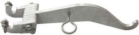
RT401-0573
Double plate triangular rocker arm hot end yoke, applied in suspension insulators chain, manufactured in laminated aluminum alloy.
Rated Work Capacity: 4990 daN (11000 lb)
Approx. Weight: 4.80 kg (10.58 lb)
260 CONDUCTOR SUPPORT EQUIPMENT RITZ FERRAMENTAS G
Structure Yokes
| | FLV4783-22
FLV31455-1
Steel structure yoke
Designed and manufactured in accordance with IEC61236 standard, constructed from aluminum alloy sheets. A practical and extremely versatile tool for the replacement of insulator strings. It adjusts easily and quickly onto the structure, serving as support for strain poles to relieve the mechanical tension of a string of suspended insulators, in conjunction with strain poles and energized side yokes.
Allows an adjustment of 75 to 200 mm between the support brackets on the structure. It has a center-to-center distance of 550 mm (FLV4783-22) and 660 mm (FLV31455-1) for the mounting of the pivots for strain poles.
Rated Work Capacity: 6804 daN (15000 lb)
Approx. Weight: 21.00 kg (46.30 lb)
| FLV400-0219
Tower yoke
Approx. Weight: 23.00 kg (50.70 lb)

Designed and manufactured in accordance with the IEC61236 standard, constructed from aluminum alloy sheets It is generally used in“H”crossarms, with design and applications similar to the metal structure yoke (FLV4783-22) To adapt to different crosshead sizes, the screws that fix it can be adjusted in three positions from center to center (230, 280 and 330 mm) and 230 to 305 mm in relation to the vertical.
Rated Work Capacity: 6804 daN (15000 lb)
Approx. Weight: 13.99 kg (30.84 lb)
| RC400-0445
Metal crossarm yoke
It is designed for use at the end of the crossarm, coupled through the RT4000838 support when necessary. It has its rotary couplings and allows the correct alignment of the strain poles in relation to the yoke on the energized side
Rated Work Capacity: 6804 daN (15000 lb) when limited to a 45° angle: 4082 daN (9000 lb)
Approx. Weight: 8.30 kg (18.30 lb)
| RT400-0838
Metal crossarm adapter support
It is used in conjunction with the metal crossarm yoke (RC400-0445) when the metal crossarm does not originally have the yoke attachment bracket. Built in aluminum alloy, it is fixed to the metal crossarm through the chain stretcher.
Rated Work Capacity: 6804 daN (15000 lb)
Approx. Weight: 5.30 kg (11.68 lb)


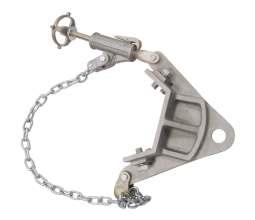
261 CONDUCTOR SUPPORT EQUIPMENT RITZ FERRAMENTAS G
RT400-0838
RC400-0445
FLV4783-22
FLV400-0219
660 mm

660 mm


| RC401-0168
Living double side yoke for single “V” suspension string
Attachable to the yoke plate through the sticks with adjustable pole clamp or strain pole clevis-eye. It has a bronze adapter to fit the yoke plate. Used on the energized side. Made of extra strong rolled aluminum plate.
Rated Work Capacity: 6804 daN (15000 lb)
Approx. Weight: 6.50 kg (14.33 lb)
| RT401-0689
V-side double yoke for “V” suspension string and double anchor
Similar to RC401-0168, however, without the bronze adapter. Usually used on the energized side of double-anchored “V” suspension strings, with reduced coupling spaces
Rated Work Capacity: 6804 daN (15000 lb)
Approx. Weight: 3.50 kg (7.72 lb)
| RH4794
Suspension hot yoke with 3 ½” saddle
It is typically used on the hot-end of single “I” suspension strings on 220 to 345 kV twin-cable transmission lines. Constructed of heat-treated cast aluminum alloy, it has a duplicator saddle (RH4794-1) installed at its base.
Rated Work Capacity: 6804 daN (15000 lb)
Approx. Weight: 7.60 kg (16.76 lb)
NOTA
The RH4794-2 duplicator support saddle model (which is also used in conjunction with the Jugo RH4794) can be purchased separately when required.

660 mm


| RC401-1722
Living double side yoke for single “V” suspension string
Used in conjunction with strain poles (RC401-2144 to RC401-2149 series), it is normally attached to the hot-end yoke plate of the “V” suspension string
Constructed of rolled aluminum plate
Rated Work Capacity: 6804 daN (15000 lb)
Approx. Weight: 10.30 kg (22.71 lb)
For certain applications, this yoke can be replaced by model RH4794.
| | RH4794-1 (3 ½”)
Duplicator support saddle
RH4794-2 ( 12”)
They are used in conjunction with the RH4794 yoke for coupling to the insulator string yoke plate with continuous 360° rotation.
They have two sizes (89 and 305 mm) for better fit to the yoke plate and both sizes are made of aluminum alloy
Rated Work Capacity: 6804 daN (15000 lb)
Approx. Weight: 0.69 kg (1.52 lb) 1.00 kg (2.20 lb)
262 CONDUCTOR SUPPORT EQUIPMENT RITZ FERRAMENTAS G
RC401-0168
RT401-0689
RH4794-1
RH4794-2
RH4794
RC401-1722
STATIC GROUND
It is designed to eliminate the nuisance of the electrostatic charge during coupling and decoupling of insulator strings when working on energized installations. It also dissipates the static charge through the copper cable (25 mm² size x 2.0 m long) and clamp for connection to structure hardware or conductor cables.
To ground the insulator string on the de-energized side, the grounding clamp must be installed on the structure angle and the pole jaws must be installed on the insulator hardware closest to the structure
For bare-hand work, the clamp should be installed to the energized hardware and the stick jaws to the second insulator on the energized side
Constructed with Ø 32 mm RITZGLAS® tube and 0.76 m in total length. Its bronze alloy jaws are designed for Ø 64 to 152 mm insulator hardware
The clamps for connection to the structure have two installation versions (with T-handle and eyescrew). Both clamps are constructed of bronze alloy, with the clamp body being in aluminum alloy


263 CONDUCTOR SUPPORT EQUIPMENT RITZ FERRAMENTAS G Catalog Reference Description Insulating Length (m) Approx. Weight kg lb RC600-0000 Static grounding with T-handle connecting clamp 0.43 3.10 6.83 RHG4230-1 Static grounding with connecting eyescrew 3.30 7.27
RC600-0000
RHG4230-1
CRADLE
There are three basic cradle solutions to meet a variety of insulator maintenance and replacement requirements
All are built with RITZGLAS® tubes for work on 110 to 800 kV anchor or suspension strings
| Single Insulator Cradles
It is generally used in 110 to 230 kV strings, supported by a pair of wire tongs or strain link stick
| Cradle with fittings
It is used in 345 to 500 kV strings and in combination with cradle supports to allow insulators movement.
| Cradle with bracket (side opening) for extra high voltage
It is used in anchor strings up to 800 kV to allow single or multiple string removal.

264 CONDUCTOR SUPPORT EQUIPMENT RITZ FERRAMENTAS G
Single Insulator Cradles
It is used to change insulators in the string itself or to lower it to the ground In anchor strings or angled strings, this cradle is used in conjunction with support rods. As for “I” suspensions, strain poles are used.
Constructed with Ø 38 mm RITZGLAS® tubes, this series of single cradles has two steel pins at their front, which are used to support the insulator string with a pair of wire tongs or strain link stick.
At the rear of the crib there are large eyes and ropes for coupling to the structure as an anchor point. In this way, the insulators can be raised or lowered to a more suitable position for replacement.
When lowering the insulator string is not necessary, the cradles are mounted to the eyes located on the yokes coupled to the strain poles.

SPARE PARTS AND COMPONENTS
265 CONDUCTOR SUPPORT EQUIPMENT RITZ FERRAMENTAS G
Catalog Reference Description Approx. Weight kg lb FLV19067-1 Cradle center spacer 0.80 1.76 FLV17458-1 Metal spacer with side cradle holders 1.00 2.20 FLV17445-1 Metal spacer with side eyes and 2.50 m insulating rope at its cradle ends 1.60 3.53 RH4540 RITZGLAS® tube, Ø 38 mm x 1.22 m, with plastic end fitting 0.90 1.98 RH4540-1 RITZGLAS® tube, Ø 38 mm x 1.83 m, with plastic end fitting 1.30 2.87 RH4540-2 RITZGLAS® tube, Ø 38 mm x 2.44 m, with plastic end fitting 1.70 3.75 RH4540-3 RITZGLAS® tube, Ø 38 mm x 3.05 m, with plastic end fitting 2.10 4.63 RH4540-4 RITZGLAS® tube, Ø 38 mm x 3.65 m, with plastic end fitting 2.50 5.51
Catalog Reference Maximum Capacity Insulating Length (m) Approx. Weight kg lb RH1840-4 6 insulators up to Ø 254 mm 1.22 5.80 12.79 RH1840-6 10 insulators up to Ø 254 mm 1.83 7.00 15.43 RH1840-8 14 insulators up to Ø 254 mm 2.44 8.30 18.30 RH1840-10 18 insulators up to Ø 254 mm 3.05 12.20 26.90 RH1840-12 22 insulators up to Ø 254 mm 3.66 14.70 32.41
TRANSMISSION INSULATOR CRADDLES


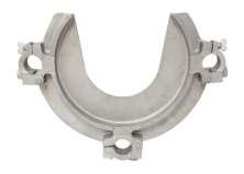


Cradle with fittings
It is used to change insulators in strings up to 500 kV. It is also required to lower “V” or anchor insulator strings and to lift “I” suspension insulators
The deep design of the cradle is a safe way to prevent accidental fall of the insulator string. In addition, it is reinforced by the upper insulator retaining plate, which securely holds it during transport.
The insulator plate has dual use: on one side fits insulators up to Ø 273 mm; and, on the opposite side, it adapts to insulators up to Ø 286 mm.
The cradle can be easily lowered or lifted for insulator change through the forged steel swivel eyes at one end and the other with the aid of the steel handle (R070184) attached to a strain link stick, and it also has an auxiliary hook (R068922).
The steel strap and hook are supplied with the cradle.
SPARE PARTS AND COMPONENTS
266 CONDUCTOR SUPPORT EQUIPMENT RITZ FERRAMENTAS G
Catalog Reference Maximum Capacity Insulating Length (m) Approx. Weight kg lb RC401-0015 25 insulators up to Ø 286 mm 3.40 16.40 36.16 RH1950-9 19 insulators up to Ø 286 mm 2.69 14.90 32.85
EHV THROUGH DESIGN INSULATOR CRADLES
Catalog Reference Description Approx. Weight kg lb FLV17453-1 Cradle center metal spacer 1.60 3.53 FLV17446-1 Aluminum cradle plate 2.60 5.73 FLV17447-1 Metal spacer with side cradle holders 1.60 3.53 R068922 Plastic coated steel hook 0.55 1.21 R070184 Galvanized steel handle 1.10 2.43 FLV18594-4 Ø 38mm RITZGLAS® tube for RC401-0015, with plastic terminal and metal head 3.23 7.12 FLV18593-4 Ø 38mm RITZGLAS® tube for RC401-0015, with plastic terminals 2.60 5.73 FLV18594-3 Ø 38mm RITZGLAS® tube for RH1950-9, with plastic terminal and metal head 2.70 5.95 FLV18593-3 Ø 38mm RITZGLAS® tube for RH1950-9, with plastic terminals 2.07 4.56
R068922
FLV17453-1
FLV17447-1
FLV17446-1
R070184
Cradle Support

| RH1950-90
It is made with Ø 64 mm RITZGLAS® tube and its main structure has a heattreated aluminum head with forged steel swivel eye and three pairs of hooks, which are coupled to a spiral link pole and act as a support.
Insulating Length: 2.97 m
Rated Work Capacity: 227 daN (500 lb)
Approx. Weight: 13.40 kg (29.54 lb)

267 CONDUCTOR SUPPORT EQUIPMENT RITZ FERRAMENTAS G
Support Cradle
It has been developed for the selective removal of a single insulator string, particularly, in double, triple, or quadruple anchor strings. Using this cradle, it is not necessary to remove the upper strings to extract the lower strings.
Constructed with Ø 64 mm RITZGLAS® tube as its main element, it has three Ø 38 mm pipes.
The tubes has swiveling eyes at its ends
0.38 m hooks are used in mountings with single or double anchor strings, while with the 0.79 m hook is used to remove quadruple lower anchor strings.
The insulator plate has dual use: on one side fits insulators up to Ø 279 mm; and, on the opposite side, it adapts to insulators up to Ø 324 mm.
In conjunction with the cradle, tie rods are provided for coupling to the boom pole, a plate for retaining the upper insulator, hook arrangements, and metal spacers.
268 CONDUCTOR SUPPORT EQUIPMENT RITZ FERRAMENTAS G Catalog Reference Description Rated Work Capacity Approx. Weight. daN lb kg lb RC401-0354 Long insulating cradle of 4.83 m , 4 long support hooks of 0.38 m, 2 metal spacers and 1 plate 454 1000 66.00 136.69 RC401-0355 Long insulating cradle of 4.83 m , 4 long support hooks of 0.79 m, 2 metal spacers and 1 plate 64.00 141.10 RC401-0356 Long insulating cradle of 3.91 m , 4 long support hooks of 0.38 m, 2 metal spacers and 1 plate 58.50 128.97 RC401-0357 Long insulating cradle of 3.91 m , 4 long support hooks of 0.79 m, 2 metal spacers and 1 plate 60.50 133.38 RC401-0358 Long insulating cradle of 2.69 m , 3 long hooks of 0.38 m and 1 plate 227 500 42.60 93.92 RC401-0359 Long insulating cradle of 2.69 m , 3 long hooks of 0.79 m and 1 plate 44.00 97.00


269 CONDUCTOR SUPPORT EQUIPMENT RITZ FERRAMENTAS G
Item Catalog Reference Description Approx. Weight kg lb 1 FLV01852-1 Cradle tie rod support 1.15 2.54 2 RC401-0361 Cradle support hook with ® Ø 51 x 390 mm RITZGLAS® 4.50 9.92 RC401-0362 Cradle support hook with ® Ø 51 x 810 mm RITZGLAS® 5.70 12.55 3 FLV03460-1 Cradle metal spacer 2.60 5.73 4 RC401-0455 Insulator plate 3.15 6.95 5 RE402-0138 Ø 64 mm clamp for rod 0.80 1.75 6 FLV18595-1 Ø 64 X 4830 mm (insulated) RITZGLAS® tube with plastic terminal and eye head 8.80 19.40 FLV18595-2 Ø 64 X 3890 mm (insulated) RITZGLAS® tube with plastic terminal and eye head 7.45 16.42 FLV18595-3 Ø 64 X 2675 mm (insulated) RITZGLAS® tube with plastic terminal and eye head 5.40 11.90 7 FLV18594-1 Ø 38 X 4835 mm (insulated) RITZGLAS® tube with plastic terminal and eye head 4.50 9.92 FLV18594-2 Ø 38 X 3920 mm (insulated) RITZGLAS® tube with plastic terminal and eye head 3.60 7.94 FLV18594-3 Ø 38 X 2705 mm (insulated) RITZGLAS® tube with plastic terminal and eye head 2.60 5.75 8 FLV18593-1 Ø 38 X 4874 mm RITZGLAS® tube with plastic terminal 3.90 8.60 FLV18593-2 Ø 38 X 3954 mm RITZGLAS® tube with plastic terminal 2.95 6.50 FLV18593-3 Ø 38 X 2734 mm RITZGLAS® tube with plastic terminal 2.20 4.85 9 FLV03457-2 Ø 38 x 349 mm (insulated length) RITZGLAS® pole with tie-down head (clevis type) and eye head 2.15 4.74 FLV03457-3 Ø 38 x 806 mm (insulated length) RITZGLAS® pole with tie-down head (clevis type) and eye head 2.50 5.52 FLV03457-5 Ø 38 x 1263 mm (insulated length) RITZGLAS® pole with tie-down head (clevis type) and eye head 2.85 6.28 FLV03457-6 Ø 38 x 1416 mm (insulated length) RITZGLAS® pole with tie-down head (clevis type) and eye head 3.00 6.61 1 6 7 2 4 5 8 5 5 3 9 9
SPARE PARTS AND COMPONENTS
RC401-0455
FLV03460-1
RC401-0361
FLV01852-1
RC402-0790

“J” - HOOK ASSEMBLY
It is used as an efficient alternative solution to remove lower insulators in a triple string
Constructed with RITZGLAS® tube, one end features a freely rotating steel hook for quick and easy string adjustment. To ensure the protection of the insulators, the hook has a plastic coating.
For complete cradle assembly, with the “J” hook assembly, the RC401-0354 to RC401-0359 series cradle main support must be mounted.
“J”- HOOK ASSEMBLY
SPARE PARTS AND COMPONENTS
Catalog Reference Description
FLV03457-2 Small crib tie rod
RC402-0790 “J”- Hook Assembly
FLV18595-1 Ø 64 mm Tube w/ plastic terminal and cradle eye
RE402-0138 Ø 64 mm clamp for rod
FLV03457-6 Cradle tie pole
FLV01852-1 Cradle tie rod support

270 CONDUCTOR SUPPORT EQUIPMENT RITZ FERRAMENTAS G
Catalog Reference Ø (mm) Length (m) Rated Work Capacity Approx. Weight daN lb kg lb RC402-0790 51 0.91 113 250 4.00 8.81
TROLLEY POLE
It is used to transport the suspension insulator string to the structure
Constructed with RITZGLAS® tubing and aluminum and steel metal parts, the trolley pole can be installed horizontally under the tower crossarm through the metal structure saddle
The scoop (RH4723-2), with a socket for Ø 267 to 273 mm insulators, is properly installed on a Ø 64 mm or 76 mm pole, with swivel eye and through the single sheave or double sheave. The latter is used in large strings or heavy insulators, thus forming the trolley pole assembly.
The scoop coupled to the stick is mounted under the first top insulator of the string for removal and horizontal movement for maintenance, and to return it to the original position.
TROLLEY POLE
NOTE
SUSPENSION STRING - The , and trolley fork suspension tool tandem trolley pole set is for a rated load of up to 400 daN (880 lb), however the following procedures should be observed in its application:
1. Always use pulleys with 64 mm clamp (RC400-0152). tandem
2. The recommended trolley pole size for this load is Ø 64 mm (RH4721-112).
3. The maximum distance between the trolley pole attachment points on the structure to prevent excessive bending is 2 m.
4. The coupling of the Ø 64 mm clamp to the Tandem Trolley fork suspension tool must be within 500 mm of the scoop center.


271 CONDUCTOR SUPPORT EQUIPMENT RITZ FERRAMENTAS G
Catalog Reference Ø (mm) Insulating Length (m) Approx. Weight kg lb RH4721-112 64 3.51 9.50 20.94 RC400-0546 76 3.51 13.80 30.42
Catalog Reference Description Approx. Weight. kg lb RH4723-2 Fork Suspension Tool Attachment for Ø 64 mm pole 6.40 14.11 RH4723-4 Single Trolley Wheel with Ø 64 mm pole clamp 3.60 7.94 RC400-0152 Tandem Trolley Wheel with Ø 64 mm pole clamp 7.30 16.09
COMPONENTS
RH4723-4
RC400-0152
RH4723-2
272 CONDUCTOR SUPPORT EQUIPMENT RITZ FERRAMENTAS G

Conductive Suits . . . . . . . . . . . . . . . . . . . . . . . . . . 275 Bare-hand Working Chair . . . . . . . . . . . . . . . . . . 277 Inspection Trolley . . . . . . . . . . . . . . . . . . . . . . . . . 278 Bare-Hand Stick . . . . . . . . . . . . . . . . . . . . . . . . . . . 279 BARE-HAND EQUIPMENT GROUP H Access our site.
BARE-HAND EQUIPMENT GROUP H
CONDUCTIVE SUITS
Conductive suit for work on high voltage transmission lines and substations up to 800kV AC and 600kV DC. It allows the electrician to equalize his/her potential with the electric field of the energized point where the work will be performed
The conductive suits works based on the Faraday Cage principle, making maintenance work on energized systems safe and comfortable
Made of high-tech polyamide fabric lined with cotton and silver microfiber and reinforced seams. Its anatomical construction allows the electrician to wear a safety helmet under the hood of the conductive suit without limiting mobility and maintaining the Faraday Cage effect around his/her head.
Available in three sizes: Medium, Large, and Extra Large.
Routine test reports are provided along with the conductive suit. These test data are a parameter of utmost importance for continuous monitoring of conductive suit quality and performance, even after years of use and washing.
The conductive suit meets the requirements of IEC 60895.

275 BARE-HAND EQUIPMENT RITZ FERRAMENTAS H


CONDUCTIVE SUITS

CONDUCTIVE BOOT
276 BARE-HAND EQUIPMENT RITZ FERRAMENTAS H
Catalog References Size Brazil USA Europe RC417-0623 37 6 39 RC417-0624 38 7 40 RC417-0624/5 39 7.5 41 RC417-0122/5 40 8.5 42 RC417-0123/5 41 9.5 43 RC417-0124 42 10 44 RC417-0125 43 11 45 RC417-0126 44 12 46 RC417-0126/5 45 12.5 47 RC417-0625/5 46 13.5 48
Catalog Reference Description Size Capacidade FLV30620-1 Pants, jacket with hood, socks, gloves, and storage bag Small 800kV Alternating Current / 600kV Direct Current FLV30620-2 Pants,
and storage bag Medium FLV30620-3 Pants,
and storage bag Large
Pants,
Extra Large
Conductive socks Only FLV30623-1 Conductive gloves Only FLV29842-4 Pants, jacket with hood, socks, gloves, face screen, and storage bag Medium 1000kV Alternating Current / 800kV Direct Current FLV29842-1 Pants, jacket with hood, socks, gloves, face screen, and storage bag Large
and
Extra Large
Only
jacket with hood, socks, gloves,
jacket with hood, socks, gloves,
FLV30620-4
jacket with hood, socks, gloves, and storage bag
FLV30622-1
FLV29842-2 Pants, jacket with hood, socks, gloves, face screen,
storage bag
FLV29842-3 Face screen mask
FLV29842-3 - Face screen for 1000kV AC and 800kV DC suit
BARE-HAND WORKING CHAIR
| FLV12563-1
Designed for safe, quick, and comfortable transport of the electrician from the ground to the maintenance areas in the structure or close to the power supply
Its lightweight, sturdy anatomical construction design with RITZGLAS® poles and aluminum fittings allows vertical and horizontal travel operations with absolute precision in approaching the power supply.
It has a device for continuous rotation from the point of connection with the boom, to better position the electrician when transitioning from the chair to the conductor. This device comes with the chair and is optional.
The chair is detachable and has a bag for easy transport, packaging, and storage.
Maximum workload capacity: 120 daN (265 lb)
Approx. Weight: 19.80 kg 43.65 (lb)


277 BARE-HAND EQUIPMENT RITZ FERRAMENTAS H


INSPECTION TROLLEY
Essential tool for inspection and maintenance of transmission lines
Through the bare-hand method, the electrician has safe and ergonomical access to the conductors. Its advancing and retreating movements are controlled by a rope from the tower or the ground
Mostly made of aluminum this equipment is designed for easy handling during transport, installation, and use.
INSPECTION TROLLEY
ACESSORIES

278 BARE-HAND EQUIPMENT RITZ FERRAMENTAS H
Catalog Reference Description Work Capacity Rated Approx. Weight daN lb kg lb FLV21045-1 for 4 conductors 120 265 38.00 83.75 FLV21549-1 for 3 conductors 55.50 122.36
FLV21045-1
FLV21549-1
Item Quant. Unit. Catalog Reference Description 01 220 m RM1895-3 Polypropylene rope 02 06 pc FLV04803-3 Rope insulating stick
BARE-HAND STICK
| FLV02544-1
Designed to connect the tap wire of the conductive suit with the energized conductor, in order to establish potential equalization, avoiding discomforts to the electrician during the work
It is through the bare-hand stick that the first contact of the electrician with the energized conductor is made. Similarly, at the end of the work, it must be disconnected last, thus avoiding electric arcs in the electrician.
Upon returning to ground potential, the stick must first touch the structure to discharge static energy.
Made of a Ø 32 mm RITZGLAS® tube with an insulating length of 340 mm and has a rest strap for the stick and a tap wire for the conductive suit.
Approx. Weight: 1,60 kg (5.53 lb)
CONNECTION TYPE
Detachable clamp,: it is also mounted by twisting the stick, but the electrician can remove the stick, leaving only the mounted clamp. (This clamp has a quick coupling head to hold the clamp eye bolt firmly and securely).
Minimum Opening: 12 mm
Maximum Opening: 48 mm

279 BARE-HAND EQUIPMENT RITZ FERRAMENTAS H
280 BARE-HAND EQUIPMENT RITZ FERRAMENTAS H

INSTRUMENTS GROUP I Phase Tester. . . . . . . . . . . . . . . . . . . . . . . . . . . . . . . 283 Insulator Tester. . . . . . . . . . . . . . . . . . . . . . . . . . . . 285 Ritz Tester . . . . . . . . . . . . . . . . . . . . . . . . . . . . . . . . . 286 Microammeter . . . . . . . . . . . . . . . . . . . . . . . . . . . . 287 Hot Line Tester 288 Contact Tester. . . . . . . . . . . . . . . . . . . . . . . . . . . . . 289 Contact Tester - CSU . . . . . . . . . . . . . . . . . . . . . . . 290 Contact Tester - Underground System . . . . . 290 Contact Tester - Direct Current. . . . . . . . . . . . . 291 Multi-Purpose Tester . . . . . . . . . . . . . . . . . . . . . . 291 Super Tester 292 Glove Tester . . . . . . . . . . . . . . . . . . . . . . . . . . . . . . . 293 Access our site.
INSTRUMENTS GROUP I
PHASE TESTER
A portable equipment for easy and safe phase sequence determination and comparison, as well as AC, phase-to-phase, or phase-to-ground voltage readings in 1 kV to 80 kV transmission and distribution circuits
The basic unit is comprised of a 1 kV to 16 Kv direct reading galvanometer and a 6.50 m reel with hielded cable, mounted on two RITZGLAS® sticks, which are high impedance units required for readings on the instrument.
Voltages above 16 kV require extensions (RH1876-4 for 48 kV and RH1876-2 for 80 kV). These extensions are coupled to the threaded end of the instrument stick for indirect reading, that is, x3 full scale for 48 kV and x5 full scale for 80 kV.
A pair of extensions must be used for 48 kV (RH1876-4) and two pairs for 80 kV (RH1876-2). Length of each unit: 630 mm.
The Calibration Device (H1876/B-AFT) is designed to calibrate the phase detector before use, especially after a long inactivity period. It generates a digital signal to the phase detector so that the user can compare the galvanometer reading with the value on the calibration device display
This Calibration Device must be ordered separately.
Power supply: 9V battery

283 INSTRUMENTS RITZ FERRAMENTAS I

PHASE TESTER


ACCESSORY


284 INSTRUMENTS RITZ FERRAMENTAS I
Catalog Reference Description Aprox. Weigh kg lb RH1876 Complete phase tester kit for phases up to 16 kV, including detector, case, two universal sticks, bag for universal sticks 10.90 24.03 ITR-E-00863 Complete phase tester kit, including detector, resistor extension kit for 48 kV, case, two universal sticks, bag for universal sticks 12.00 26.45 RH1876-1 Phase tester and case for 16 kV only 8.35 18.41 RH1876-2 Resistor extension kit for 80 kV Phase Detector 2.84 6.26 RH1876-4 Resistor extension kit for 48 kV Phase Detector 1.42 3.13 H1876/B-AFT Phase tester calibration device 1.00 2.20
Catalog Reference Description Aprox. weight kg lb RH1760-1 Ø 32 mm Universal stick and 1.75 m insulated length 1.30 2.87
630 mm (2 ft)
RH1876-4 RH1876-1
H1876/B-AFT
RH1876
INSULATOR TESTER
| TILV-16/DT
A portable device designed to quickly locate a faulty isolator in the insulator chain in hot distribution and transmission circuits
Aprox. Weight: 1.13 kg (2.49 lb)
Its working principle is based on measuring the potential difference in the tested insulator disc. A high impedance galvanometer indicates this potential difference for comparisons with other isolator discs in the same system. Thus, a defective isolator will show a reading considerably lower than the others.
It can be used to evaluate pin insulators, one piece isolators, multipart pin insulators, and disc insulators.
It is made of fiberglass tubing and housing, with quick and multiangular adjustment of contact tips. The insulator tester is designed to test any insulator measurement and to make other adjustments for better viewing
The instrument has a 3-position switch on its backside to change sensitivity for a better selection of pointer range
 | TILV-16/AFT


The calibration device is designed to check the insulator tester before use, especially after a long inactive period.
Aprox. Weight: 1.00 kg (2.20 lb)
It generates a digital signal to the insulator to compare the values shown in the calibration display and the insulator tester galvanometer reading.
285 INSTRUMENTS RITZ FERRAMENTAS I
TILV-16/AFT
TILV-16/DT


RITZ TESTER
A portable device for periodic electrical testing of hot line insulated poles, hot sticks and poles, hot line ladders and insulated scaffolds that detects the leakage current caused by moisture, cracks, and impurities on or inside the insulated poles.
Operation is easy and simple, and only requires a single operator, through the direct contact of the Ritz Tester with the surface to be tested, indicating a “PASS” or “FAIL” graph, according to the leakage current of the tested element.
This instrument simulates the test specified in the ASTM F-711 standard. A test carried out by the Ritz Tester offers a guarantee that the equipment is ready for use. It can not be used as a reporting test.
There are four versions available:
| | | | LS-80 LS-81 RT-110 RT-220 (standard sizes) (reduced sizes)
These models perform electrical tests corresponding to an applied voltage of 100 kV in 30 cm according to the standard. To perform the test, the stick must be supported horizontally on two easels.
| | LS-80/WD LS-81/WD
These models can be used for electrical tests on wet and dry sticks through a key switch on the front panel of the instrument. In the wet function, an electrical test corresponding to a voltage of 75 kV in 30 cm is reproduced. And the dry function corresponds to a voltage of 100 kV in 30 cm.
286 INSTRUMENTS RITZ FERRAMENTAS I
LS-80 RT-110 Catalog Reference Description Dimensions (mm) Aprox. weight Instrument Case kg lb kg lb LS-80 For 110 V 200 x 365 x 310 5.30 11.68 5.20 11.46 LS-81 For 220 V RT-110 Reduced model, 110 V 155 x 250 x 250 3.40 7.50 2.80 6.17 RT-220 Reduced model, 220 V LS-80/WD WET/DRY, for 110 V 200 x 365 x 310 5.30 11.68 5.20 11.46 LS-81/WD WET/DRY, for 220 V
MICROAMMETER
A device that measures leakage current of insulated structures in direct contact with the hot line
It is designed to measure and monitor leakage current in insulating structures such as ladders, scaffolds, man basket insulated arms, among others.
| RC402-0288
Analog Micro Ammeter
It measures leakage currents of up to 200 µA.
Aprox. Weight: 1.50 kg (3.30 lb)
| MD800
Digital Micro Ammeter
It measures and monitors leakage currents of up to 800 µA.
Aprox. Weight: 3.12 kg (6.88 lb)
The maximum allowed leakage current value for the structure to be monitored can be set on the MD800 and sound and light will be emitted if the leakage current value is higher than the value set on the device.
Designed to operate on insulating structures that are in contact with transmission lines of up to 500 kV.


287 INSTRUMENTS RITZ FERRAMENTAS I
RC402-0288
MD800


HOT LINE TESTER
Electronic instrument to detect the absence of alternating voltage in distribution lines, substations, and transmission lines, with bare conductors
Operation Frequency: 60 Hz
It is required due to the high voltage spikes when system power is restored. Thus, the electrician can carry out safety procedures while the system is deenergized
Developed in accordance with the IEC 61243-1/09 international standard, it includes an operation testing system and standby status.
*Weight without packaging
The clamp mounted instrument model can be used in bare conductor networks or compact networks
288 INSTRUMENTS RITZ FERRAMENTAS I
Catalog Reference Voltage Ranges Voltage Class Instrument Color Aprox. weight* kg lb NHL 10-40 10 kV - 40 kV Medium Orange 0,72 1,59 NHL 20-80 20 kV - 80 kV High-medium Orange NHL 60-240 60 kV - 240 kV High Black
Catalog Reference Voltage Ranges Voltage Class Instrument Color Aprox. weight* kg lb NHL 10-40/GR 10 kV - 40 kV Medium Orange 0,75 1,65
without packaging NHL 10-40/GR
voltage instrument High voltage instrument
*Weight
Medium
CONTACT TESTER
The contact AC voltage detector instrument is designed to detect the presence of voltage in alternating current installations in transmission lines, distribution, substations, and cubicles with phase-to-phase voltage with bare conductors.
Its advanced electronic circuit ensures a safe and precise response, providing visual and audible indications to ensure an effective response.

In compliance with the requirements of the Regulatory Standard for Safety in Electrical Installations and Services NR-10 (item 10.5.1 - C - Verification of voltage absence), we offer models tested according to the ABNT NBR IEC 61243-1:2020 and the international standard IEC 61243:2021.
These instruments are designed with an external compartment for battery replacement, ensuring safety during the replacement process without compromising the electronic board They also feature a high degree of protection and sealing against temperature and humidity variations, as well as improvements in shielding, impact resistance, vibration, and weather resistance.


289 INSTRUMENTS RITZ FERRAMENTAS I
voltage
Low voltage
Catalog Reference Voltage Ranges Voltage Class Instrument Color Aprox. Weight kg lb CT 0,05-1 50V - 1 kV Low Brown 0.29 0.63 CT 0,07-1 70V - 1 kV Low Brown 0.29 0.63 Work frequency: 60 Hz
oltage instrument High
instrument
instrument
Catalog Reference Voltage Ranges Voltage Class Instrument Color Aprox. Weight kg lb CT 5-15 5 kV - 15kV Medium Orange 0.29 0.63 CT 3,8-36 3.8 kV - 36 kV Medium Orange 0.29 0.63 CT 12-36 12 kV - 36 kV Medium Orange 0.38 0.84 CT 10-40 10 kV - 40 kV Medium Orange 0.38 0.84 CT 60-240 60 kV - 240 kV High Black 0.51 1.19 CT 60-440 60 kV - 440 kV High Black 0.51 1.19 Work frequency: 50-60 Hz
CONTACT TESTER - CSU
An instrument used to check live circuits for voltage. It contains sound and light indicator signals This equipment model signals the presence of voltage only when the equipment electrode is in contact with the hot point to be tested.
Operation Frequency: 60 Hz
Thanks to its universal fitting head, this model can be used for other functions such as disconnecting fuse switches. Its pole is subjected to the tensile test with the same strain as the hot stick.

**


CONTACT TESTER
UNDERGROUND SYSTEM
An AC voltage detector designed to detect voltage in elbow and straight connectors in underground networks. Its contact electrode has been designed to cap and uncap these types of connectors for testing.
TECHNICAL CHARACTERISTICS
- Stand-by equipment;
- Light and sound indication of voltage;
- Built-in self-test circuit;
- Elbow contact electrode;
- Universal adapter for hot stick or pole.
290 INSTRUMENTS RITZ FERRAMENTAS I
Catalog Reference Voltage Ranges Voltage Class Instrument color Aprox. Weight* kg lb CT-CSU-3.8-36/SB** 3.8 kV - 36 kV Medium Orange 0,65 1,43 CT-CSU-10-40 10 kV - 40 kV * Weight without packaging
Does not cover the IEC 61243-1 standard
Catalog Reference Voltage Range Voltage Class Instrument Color Aprox. Weight kg lb CT-RS/C 2-6 2 - 6 kV Low Orange 0.34 0.75 CT-RS/C 3,8-36 3.8 - 36 kV Medium Orange 0.34 0.75
CONTACT TESTER DIRECT CURRENT
| CT-CC 0.5-5
Voltage detector designed for contact voltage detection. Two-pole equipment where a clamp is grounded and the electrode is used to detect voltage at the desired point.
Aprox. Weight: 1.10 kg (2.43 lb)
TECHNICAL CHARACTERISTICS
- Voltage range: 500 V - 5 kV;
- Equipment with on/off/test switch;
- Light and sound indication of voltage;
- Universal adapter for hot stick or pole;
- Built-in self-test circuit with cable test circuit.

MULTI-PURPOSE TESTER
Designed to safely for contact and no-contact voltage detection in alternating current electrical installations with unshielded conductors. It is ideal for distribution lines, substations, and switchgears


291 INSTRUMENTS RITZ FERRAMENTAS I
Catalog Reference Voltage Range Model Aprox. Weight kg lb DMU-15 110 V - 600 V contact 601 V - 15 kV non-contact With on/off switch 0.30 0.66 DMU-25 110 V - 25 kV With on/off switch DMU-36/SB 220 V - 36 kV Stand-by
DMU (with switch)
DMU (stand-by)
SUPER TESTER
A non-contact voltage detector designed for use with a hot stick or pole The electronic circuit provides accurate and reliable indications through visual and audible signals.
This device can safely detect voltage from 1 kV in alternating current installations such as transmission and distribution lines, substations, switchgears, etc., with unshielded conductors.
It is indispensable in maintenance services on electrical installations so the electrician can be sure that the work place is de-energized, thus enabling the installation of the temporary grounding set, which will ensure the necessary safety to perform the tasks

TECHNICAL CHARACTERISTICS
- Suitable for indoor and outdoor use;
- Built-in operation test;
- Simultaneous sound and light dual signal;
- Encapsulated electronic circuit immune to temperature differences from10 °C to 60 °C;
- LED indicator for perfect device operation and battery charge condition
- Packaging: synthetic material case;
- Universal adapter for hot stick;
- Dimensions: 180 x 100 x 90 mm;
- Operation: By proximity to the electromagnetic field;
- Alarm Signal: Light - through 4 front LEDs;
Sound - through piezoelectric transducer;
- Work Frequency: 50 / 60 Hz;
- Power supply: 9 V battery - average duration for uninterrupted work 15h.
292 INSTRUMENTS RITZ FERRAMENTAS I
Catalog Reference Description Aprox. Weight kg lb H1990/ST-138 Non-contact high voltage one-pole detector in the range of 1 to 138 kV 1.00 2.20 H1990/ST-800 Non-contact high voltage one-pole detector in the range of 1 to 800 kV
GLOVE TESTER
| FLV11404-1
Designed to perform visual inspection of rubber insulating gloves of all voltage classes, allowing immediate detection of any damage that may compromise its insulating characteristics, however small it may be, anywhere on its surface. It can be used in the workplace or test laboratories. It can be operated manually by pump or connected to a compressed air source.
Aprox. Weight: 7.75 kg (17.09 lb)
Rubber insulating gloves deserve special care, including a periodic visual inspection before use, in addition to periodic electrical tests, as this equipment is subject to cracks, punctures and cuts These are damages that seriously compromise their insulating characteristics and put the user at risk

293 INSTRUMENTS RITZ FERRAMENTAS I
294 INSTRUMENTS RITZ FERRAMENTAS I

Insulated Cable . . . . . . . . . . . . . . . . . . . . . . . . . . . 297 Copper Ferrule for Cables. . . . . . . . . . . . . . . . . . 298 Bypass Clamp . . . . . . . . . . . . . . . . . . . . . . . . . . . . . 299 Insulated Handle for Clamp. . . . . . . . . . . . . . . . 300 Insulated Clamp 300 Temporary Jumper Sets 301 Support for Jumper Cable 303 Transformer Bushing Temporary Jumper . . . . . . . . . . . . . . . . . . . . . . . . 304 By-Pass Jumper Connection Device Temporary Circuits for Low Voltage Three-Phase Distribution Networks . . . . . . . . 305 Ridig Jumper. . . . . . . . . . . . . . . . . . . . . . . . . . . . . . 306 Jumper Supports. . . . . . . . . . . . . . . . . . . . . . . . . . 307 Transformer Bushing Clamp . . . . . . . . . . . . . . . 307 Temporary Jumper Protection Devices 308 Temporary Fuse Switch . . . . . . . . . . . . . . . . . . . . 308 Insulated Hanger. . . . . . . . . . . . . . . . . . . . . . . . . . 309 Temporary Switching Tool Device. . . . . . . . . . 309 Temporary Crossarm Big Jumper . . . . . . . . . . 310 Temporary Crossarm Big Jumper Circular or Double-T Pole 310 Temporary Bypass For Fuse Switch 311 Mobile Switch-Off . . . . . . . . . . . . . . . . . . . . . . . . . 312 TEMPORARY JUMPERS GROUP J Access our site.
TEMPORARY JUMPERS GROUP J
INSULATED CABLE
Used in the assembly of jumper sets for temporary electrical energy derivations in AC networks
The conductor is composed of flexible copper filaments with insulation protection of a thermosetting compound based on ethylene-propylene (EPR).
For easy identification and classification, the voltage and gauge (in AWG) are engraved along the entire length of the cable at regular intervals
INSULATED CABLE - TYPE I


297 TEMPORARY JUMPERS RITZ FERRAMENTAS J
Type I Protected Cable Detail
Catalog Reference Rated Voltage (kV) Cross Section (mm²) Cable Size (AWG) Ø External NominalOver The Coverage (mm) Maximum Current Capacity (A) Approx. Weight /m kg lb R3751 15 35 2 20.8 200 0.69 1.52 R3771 15 50 1/0 22.7 250 0.84 1.85 R3773 15 70 2/0 24.7 300 1.05 2.31 R3776 15 95 4/0 26.3 400 1.26 2.77 FLV30463-4 25 50 1/0 26.5 250 1.07 2.35 FLV30463-5 25 70 2/0 28 300 1.30 2.86 FLV30463-6 25 95 4/0 29.7 400 1.53 3.37 FLV30182-4 35 50 1/0 30.8 250 1.34 2.95 FLV30182-5 35 70 2/0 32.5 300 1.60 3.52 FLV30182-6 35 95 4/0 34 400 1.83 4.03


The Type II protected cable is composed of a flexible copper conductor made of filament strands with insulating protection of a thermosetting compound based on ethylene-propylene (EPR). Additionally, it has an external layer of thermosetting compound based on SE-6 polychloroprene, offering high resistance to abrasion, oil, heat, moisture, and ozone This outer layer is essential to ensure the cable's protection in aggressive environments
COPPER FERRULE FOR CABLES
Plain Threaded Terminal
It is designed for cable connections to protected clamps (RG4765) and bypass clamps (RC600-1743).
One of its ends has a 5/8” thread, with nut and lock washer, the other has an internal cavity to mount and then press the jumper cable.

298 TEMPORARY JUMPERS RITZ FERRAMENTAS J Catalog Reference Application Burndy Matrix No. or equivalent Compression Number Approx. Weight kg lb RC600-2598 2 AWG cable U 165 2 0.12 0.26 RC600-2599 1/0 AWG cable 0.12 0.26 RC600-2600 2/0 AWG cable 0.14 0.31 RC600-2601 4/0 AWG cable U 166 0.15 0.33
Type II Protected Cable Detail
II Catalog Reference Rated Voltage (kV) Cross Section (mm²) Cable Size (AWG) Ø External NominalOver The Coverage (mm) Maximum Current Capacity (A) Approx. Weight /m kg lb R3641 15 35 2 8 200 0.77 1.70 R3861 15 50 1/0 10 250 1.40 3.09 R3863 15 70 2/0 12 300 1.70 3.75 R3866 15 95 4/0 15 400 2.35 5.18 FLV30463-1 25 50 1/0 10 250 1.50 3.31 FLV30463-2 25 70 2/0 12 300 1.65 3.64 FLV30463-3 25 95 4/0 15 400 2.20 4.85 FLV30182-1 35 50 1/0 10 250 1.70 3.75 FLV30182-2 35 70 2/0 12 300 2.16 4.76 FLV30182-3 35 95 4/0 15 400 2.90 6.39
INSULATED CABLE - TYPE
BYPASS CLAMP
It is made of aluminum alloy and bronze alloy eyescrew suitable for hot stick work with the aid of a RITZGLAS® hot stick

299 TEMPORARY JUMPERS RITZ FERRAMENTAS J
Electrical and Mechanical Characteristics Catalog Reference RC600-1743 RG3622-1 RG3622-2 Description Aluminium body; Smooth jaw; Eyescrew; Cable connection through plain ferrule Aluminium body; Smooth jaw; Connectors and eyescrew; Cable connection through plain ferrule Aluminium body; Smooth jaw; Steel clamp for securing the protected cable with a perimeter from 51 to 70 mm; Connectors and eyescrew; Cable connection through plain ferrule Rated Current (A) 400 400 400 Shortcircuit Current (lcc) 30 cycles (kA) 30 30 30 60 cycles (kA) 23 23 23 Connection Maximum 1000 MCM Cu 1590 MCM CAA Ø 38 mm 566 MCM Cu 900 MCM CAA Ø 29 mm 566 MCM Cu 900 MCM CAA Ø 29 mm Minimum 6 Cu Ø 4 mm 6 Cu Ø 4 mm 6 Cu Ø 4 mm Cable Ferrule (mm²) Maximum 95 95 95 Minimum 16 16 16 Installation Torque (daN.m) 3.0 3.0 3,0 ASTM Designation Type I Class A Grade 5 Type I Class A Grade 5 Tipo I Classe A Grau 5 Approx. Weight (kg / lb) 0.72 / 1.59 0.72 / 1.59 0,76 / 1,68

INSULATED HANDLE FOR CLAMP
| FLV30535-1
Insulated Handle for Clamp for maximum voltage 15 kV
Tool specially designed to apply torque to the clamp eye bolt. The high dielectric strength of the material offers safety and practicality when handling the electrician. It has a polyamide body with an opening for fitting the eye screw.


INSULATED CLAMP
It is suitable for rubber glove interventions in energized installations up
36 kV. It is connected to the conductor by manual twisting, to close and open the jaw, which will mount to the conductor firmly and safely.
It is connected to the jumper cable via a copper ferrule, which must be purchased separately
Tool belonging to the group of temporary jumpers. The clamp body is constructed with orange thermoplastic protection and bronze alloy jaws.
300 TEMPORARY JUMPERS RITZ FERRAMENTAS J
Approx. Weight: 0.50 kg (1.10 lb)
Catalog Reference Description Voltage Class (kV) Clamp Connection Capability Approx. Weight Minimum Maximum kg lb RT601-0039 Insulated clamp in orange polyethylene 25 # 6 Copper Ø 4 mm 477 MCM CAA Ø 22 mm 1.25 2.76 FLV30339-2 Insulated clamp in orange polyethylene 36 # 6 Copper Ø 4 mm 954 ACSR Ø 31 mm 1.50 3.30 FLV30339-1 Insulated clamp in transparent polycarbonate 36 # 6 Copper Ø 4 mm 954 ACSR Ø 31 mm 1.50 3.30
FLV30535-1
to
| Nominal current capacity: 400 A.
TEMPORARY JUMPER SETS
Temporary bypass is a common practice for interventions on energized installations. It can be performed from a distance, with the aid of maneuvering rods or rubber glove methods.
All temporary jumpers use two copper ferrules, one at each end of the cable to connect the clamps


301 TEMPORARY JUMPERS RITZ FERRAMENTAS J 15 kV TEMPORARY JUMPER - Type I Cable RUBBER GLOVE INSTALLATION WITH CLAMP RT601-0039 Catalog Reference Clamp Connection Range Approx. Weight Minimum Maximum kg lb FLV30749-1 2 #6 Copper Ø 4 mm 477 MCM CAA Ø 22 mm 3,70 200 5.20 11.46 FLV30749-2 1/0 260 6.70 14.77 FLV30749-3 2/0 300 7.80 17.20 FLV30749-4 4/0 400 10.20 22.49 35 kV TEMPORARY JUMPER - Type II Cable RUBBER GLOVE INSTALLATION WITH CLAMP FLV30339-2 Catalog Reference Clamp Connection Range Approx. Weight Minimum Maximum kg lb FLV30765-2 1/0 #6 Copper Ø 4 mm 954 ACSR Ø 31mm 250 6.70 14.77 FLV30765-3 2/0 3.70 300 7.80 17.20 FLV30765-4 4/0 400 10.20 22.49 35 kV TEMPORARY JUMPER - Type II Cable RUBBER GLOVE INSTALLATION WITH CLAMP FLV30339-1 Catalog Reference Clamp Connection Range Approx. Weight Minimum Maximum kg lb FLV30994-2 1/0 #6 Copper Ø 4 mm 954 ACSR Ø 31mm 250 6.70 14.77 FLV30994-3 2/0 3.70 300 7.80 17.20 FLV30994-4 4/0 400 10.20 22.49
C able Size ( A W G) T ype II O v er all L ength (m) R a ted C urr ent C .ap ( A ) O v er all L ength (m) R a ted C urr ent C .ap ( A ) O v er all L ength (m) R a ted C urr ent C .ap ( A ) C able Size ( A W G) T ype II C able Size ( A W G) T ype II


302 TEMPORARY JUMPERS RITZ FERRAMENTAS J 15 kV TEMPORARY JUMPER - Type II Cable HOT STICK INSTALLATION WITH CLAMP RG3622-1 Catalog Reference Clamp Connection Range Approx. Weight Minimum Maximum kg lb FLV17443-1 2 #6 Copper Ø 4 mm 900 MCM CAA Ø 29 mm 3.70 200 4.80 10.58 FLV17443-5 4.60 5.50 12.13 FLV17443-2 1/0 3.70 260 7.10 15.65 FLV17443-6 4.60 8.40 18.52 FLV17443-3 2/0 3.70 300 8.30 18.30 FLV17443-7 4.60 9.80 21.61 FLV17443-4 4/0 3.70 400 10.70 23.59 FLV17443-8 4.60 12.80 28.22
kV
II Cable HOT STICK INSTALLATION WITH CLAMP RG3622-2 Catalog Reference Clamp Connection Range Approx. Weight Minimum Maximum kg lb FLV30752-1 1/0 #6 Copper Ø 4 mm 900 MCM CAA Ø 29 mm 3.70 250 7.23 15.94 FLV30752-2 4.60 8.58 18.92 FLV30752-3 2/0 3.70 300 8.79 18.17 FLV30752-4 4.60 9.27 20.44 35 kV TEMPORARY JUMPER - Type II Cable HOT STICK INSTALLATION WITH CLAMP RG3622-2 Catalog Reference Clamp Connection Range Approx. Weight Minimum Maximum kg lb FLV30752-5 1/0 #6 Copper Ø 4 mm 900 MCM CAA Ø 29 mm 3.70 250 8.01 17.66 FLV30752-6 4.60 9.54 21.03 FLV30752-7 2/0 3.70 300 9.71 21.41 FLV30752-8 4.60 11.65 25.68 FLV30752-9 4/0 3.70 400 10.30 22.66 O v er all L ength (m) R a ted C urr ent C .ap ( A ) O v er all L ength (m) R a ted C urr ent C .ap ( A ) O v er all L ength (m) R a ted C urr ent C .ap ( A ) C able Size ( A W G) T ype II C able Size ( A W G) T ype II C able Size ( A W G) T ype II
25
TEMPORARY JUMPER - Type

SUPPORT FOR JUMPER CABLE
| FLV31717-1
With an innovative design, this support has been developed to prevent jumper cables from becoming loose during the electrician's work, eliminating the need for improvisations such as the use of tapes or ropes to avoid falls or the formation of characteristic catenaries in cable applications
In the event of a jumper cable fall, the support plays a crucial role in preventing the crossing of two phases, avoiding risky situations. Additionally, it prevents the jumper cable from swinging in strong wind conditions.
Versatile, it can be mounted on structures with a diameter of up to 76 mm and installed on flexible coverings, bare conductors, busbars, and rods. It supports jumper cables with diameters ranging from 19 mm to 43 mm.
Approximate Weight: 0.13 kg (0.29 lb)
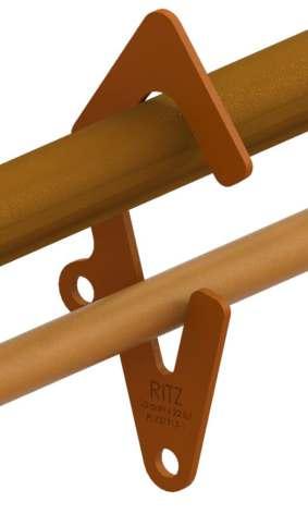
303 TEMPORARY JUMPERS RITZ FERRAMENTAS J 15 kV TEMPORARY JUMPER - Type II Cable HOT STICK INSTALLATION WITH CLAMP RC600-1743 Catalog Reference Clamp Connection Range Approx. Weight Minimum Maximum kg lb RT601-0281 2 #6 Copper Ø 4 mm 1590 MCM CAA Ø 38 mm 3.70 200 4.50 9.92 RT601-0282 4.60 5.20 11.46 RT601-0283 1/0 3.70 260 6.90 15.21 RT601-0284 4.60 8.10 17.86 RT601-0285 2/0 3.70 300 8.00 17.64 RT601-0286 4.60 9.50 20.94 RT601-0287 4/0 3.70 400 10.40 22.93 RT601-0288 4.60 12.60 27.78 O v er all L ength (m) R a ted C urr ent C .ap ( A ) C able Size ( A W G) T ype II
TRANSFORMER BUSHING TEMPORARY JUMPER
Using this tool is a standard practice in interventions in energized medium voltage installations for replacement and/or repair operations of components installed between the transformer bushings and the network, both from a distance and in rubber glove with the hot line
Arranged in two mounting versions (both built with 14.6 kV - 2 AWG size shielded cable). Rated


304 TEMPORARY JUMPERS RITZ FERRAMENTAS J
Current Capacity: 100A
Type I Cable Item Quant. Unit. Catalog Reference Description 01 01 pc FLV11179-2 Transformer bushing clamp 02 01 pc RG3622-1 Twisting clamp 03 3,5 m R3751 15 kV shielded cable 2 AWG size 04 01 pc FLV05784-1 Jumper protection device 05 1 pc RS1600-7 Insulated hanger Approx. Weight: 5.80 kg (12.79 lb)
FLV30750-1 -
Cable Item Quant. Unit. Catalog Reference Description 01 01 pc FLV11179-2 Transformer bushing clamp 02 01 pc RG3622-1 Twisting clamp 03 3,5 m R3751 15 kV shielded cable 2 AWG size 04 01 pc RC600-1895 Fuse switch Approx. Weight: 8.10 kg (17.86 lb)
FLV30751-1 - Type I
BY-PASS JUMPER CONNECTION DEVICE TEMPORARY CIRCUITS FOR LOW VOLTAGE THREE-PHASE DISTRIBUTION NETWORKS
| FLV31299-1
Versatile application as a temporary jumper and tap in low-voltage threephase energized circuits (220V/200A). It also stands out as a jumper in secondary circuits of transformers up to 75kVA in electric power distribution networks. Additionally, it is an efficient solution for temporary power transport between points during corrective or preventive maintenance procedures. The integrated circuit breaker provides additional protection against overloads and short circuits.
Equipped with a U-shaped bracket that simplifies installation and allows for attachment to handles on poles
Maximum nominal working voltage: 400Vca
Approximate weight: 20.00 kg (44.09 lb)

305 TEMPORARY JUMPERS RITZ FERRAMENTAS J
Item Qty. Unit. Catalog Reference Description 01 06 pc RT601-0039 By-pass protected clamp up to 25kV 02 01 pc - Circuit breaker 3x250A 415V 20kA 03 10.2 m R3751 Type I coopper cable 35mm² (200A) with EPR insulation up to 15kV, with 2 1.5m lengths, 2 1.7m lengths, 2 1.9m lengths 04 06 pc RC600-2622 Threaded Stud Shrouded copper Compression Ferrule 05 pc ATR17923 Heat shrink 06 06 pc ATR26446-4 Long tinned copper terminal 07 06 pc 1000976 Blue phase A heat shrink 08 01 pc 1000977 Red phase B heat shrink 09 01 pc 1000978 White phase C heat shrink 10 01 pc 1000015 Support type U 11 01 pc 5002518 Handle for support
FLV31299-1


RIGID JUMPER
Unlike conventional jumpers, where insulation is limited to the protected cable, the use of the rigid jumper provides additional safety to the operator by offering double insulation. This is possible due to its construction, which incorporates a hot line tube, RITZGLAS® without internal foam, through which the protected Type II cable passes and is supported, preventing the formation of catenary curves caused by the weight of the cable.
The handles strategically installed at the ends of this tool are highly practical for keeping the clamps retracted during installation. This is another aspect that contributes to efficiency and safety when handling with gloves, insulated sleeves, and operating hand sticks.
COMPOSITION OF THE SET
- 2.44 m RITZGLAS® tube with Ø 38 mm;
- 4.88 m Type II insulated cable for 15 kV;
- 02 Clamps for By-Pass RC600-1743;
- 02 Copper ferrule
15 kV RIGID JUMPER - Type II Cable

306 TEMPORARY JUMPERS RITZ FERRAMENTAS J
Catalog Reference Clamp Connection Range Approx. Weight Minimum Maximum kg lb RC601-0260 2 #6 Copper Ø 4 mm 1590 MCM CAA Ø 38 mm 4,88 200 7.20 15.87 RC601-0261 1/0 260 10.30 22.71 RC601-0262 2/0 300 11.70 25.79 RC601-0263 4/0 400 14.90 32.85 O v er all L ength (m) R a ted C urr ent C .ap ( A ) C able Size ( A W G) T ype II
JUMPER SUPPORTS
| RC601-0013
Pole-mounted with a chain strap, it is designed to support jumpers cables.
Constructed with Ø 64 x 1,22 m RITZGLAS® tube, composed of four swivel collar clamps (each collar has a cable clamping capacity between 19 and 38 mm in diameter), provided with an internal device to prevent the jumper from slipping, avoiding its contact with the ground
Rated working capacity on each collar: 34 daN (75 lb)
Approx. Weigh: 11.30 kg (24.91 lb)
TRANSFORMER BUSHING CLAMP
It is designed to be installed directly on the transformer bushing in energized installation interventions
Available in four models, which are unique regarding their jaw clamping devices and one is designed for angled operation.
| FLV11179-1
It has an eyescrew and is clamped using a hot stick.
Approx. Weigh: 0.80 kg (1.76 lb)
| FLV11179-3
Its jaws are driven by the “T” type screw and mounted by rubber glove.
Approx. Weigh: 0.80 kg (1.76 lb)
| FLV11179-2
It has a Ø 25 X 0.21 m insulated grip, with a rubber drip pan. It is installed by rubber glove.
Approx. Weigh: 0.80 kg (1.76 lb)


307 TEMPORARY JUMPERS RITZ FERRAMENTAS J
FLV11179-1
FLV11179-2
FLV11179-3

TEMPORARY JUMPER PROTECTION DEVICES
| FLV05784-1
It consists of a fuse holder cartridge with aluminum coupling terminals used as a temporary transformer bushing jumper component.
The clamp (RG3622-1) is mounted to the tool head from one of its hands and to the 2 AWG jumper cable from the other
Rated Current Capacity: 100A
Approx. Weigh: 11.30 kg (24.91 lb)
NOTE
The fuse link is not included and must be selected and installed by the user. High performance fuse links are recommended.
RC600-1895
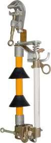
TEMPORARY FUSE SWITCH
It is designed to maintain protection during interventions on conventional distribution network fuse switches, as a temporary transformer bushing jumper component.
This switch is mounted and removed with a hot stick.
Its lower end bronze pin is for temporary jumper connection. The Ø 32 mm RITZGLAS® pipe with two rubber skirts ensures insulation.
RC600-1944

NOTES
- Fuse links are not supplied with the fuse switch and must be purchased by third parties with a maximum capacity of 100 A.
- Opening this switch under a load requires the use of a loadbuster device
- The temporary pivot lever fuse switch allows is designed to close on the opposite side of the fuse holder using a hot stick
308 TEMPORARY JUMPERS RITZ FERRAMENTAS J
Catalog Reference Description Voltage Class Approx. weight kg lb RC600-1895 Standard up to 27 kV 4.10 9.04 RC600-1944 Pivot lever 4.40 9.70
INSULATED HANGER
| RS1600-7
Used for installation of the temporary jumper on energized lines up to 34.5kV phase-phase. The insulating support holds the ends of the jumper without it energizes, allowing handling and installing the other end safely. It is fixed to the conductor by a twisting clamp with eyescrew using the hot stick
Stick made of fiberglass insulated tube impregnated with epoxy resin, bronze alloy heads and RG3403 clamp.
Nominal Load Capacity: 50 daN
Approx. Weight: 1.00 kg (2.20 lb)

TEMPORARY SWITCHING TOOL DEVICE
A device designed for the safe and economical temporary sectionalizing of circuits in distribution networks up to 25 and 36 kV, by de-energizing specific sections for maintenance.
The operation consists of mounting this tool on 1/0 to 336.4 MCM conductors (Ø 10 to 18 mm) with hot line working procedures at predetermined points This will allow releasing de-energized sections for a short period for maintenance
Installation should always be performed close to the structure and with hot line procedures
For increased operational safety, the three temporary switching tool device must not be mounted in alignment with the adjacent tool
This tool has the same characteristics as the conventional disconnect switch, with insulated components, so it is suitable for this type of intervention.
It can be opened under a load, using a loadbuster device


309 TEMPORARY JUMPERS RITZ FERRAMENTAS J
Catalog Reference Description Approx. Weight kg lb FLV13917-1 Temporary switching tool device with voltage class up to 25 kV 5.20 11.46 FLV30047-1 Temporary with voltage switching tool device class up to 36 kV 5.50 12.10


TEMPORARY CROSSARM
BIG JUMPER
| FLV13033-1
The big jumper temporary crossarm is designed for emergency interventions or power supply to temporary consumers for a specified period.
Constructed with Ø 64 mm x 1.30 m long RITZGLAS® tube, it has three fuse switches with a maximum current capacity of 100 A, a pole mounting system with two steel screws and a wing nut It can be used on installations up to 27 kV
Approx. Weight: 22.60 kg (49.80 lb)
NOTE
The fuse link is not included and must be selected and installed by the user High performance fuse links are recommended


TEMPORARY CROSSARM BIG JUMPER CIRCULAR OR DOUBLE-T POLE
It is designed for emergency interventions or power supply to temporary consumers for a specified period. It also has a mounting system for circular or square poles
| FLV29780-1
It has three fuse switches with a maximum current capacity of 100 A. It can also be used in installations up to 27 kV
Approx. Weight: 26.40 kg (58.20 lb)
| FLV30049-1
It has three disconnect switches, with a maximum current capacity of 400 A and three insulated jumpers, with 95mm² size, three-meter cable and a maximum capacity of 400 A. It can also be used in installations up to 27 kV
Approx. Weight: 45.00 kg (99.20 lb)
310 TEMPORARY JUMPERS RITZ FERRAMENTAS J
Catalog Reference Description Approx. Weight kg lb FLV13045-1 Temporary fuse switch for big jumpers up to 27 kV 4.50 9.90
ACCESSORY
FLV13045-1
FLV13033-1
FLV29780-1
FLV30049-1
TEMPORARY BYPASS FOR FUSE SWITCH
A Device used to establish an alternative route for electrical current, allowing the replacement of the fuse in various types of switches without the need to interrupt the power supply. Its installation is carried out by the distance method using an grip-all clampsticks, with the assistance of eyelets previously positioned on the heads.
Essential equipment to expedite and facilitate the maintenance of electrical systems, ensuring efficient fuse replacement and avoiding unwanted interruptions in power supply during the activity.


311 TEMPORARY JUMPERS RITZ FERRAMENTAS J
Catalog Reference Opening and Closing System Voltage Class (kV) Rated Current (A) Opening Capacity (mm) Approx. Weight Min. Max. kg lb FLV12409-1 Clamp bolt 25 100 280 442 1.47 3.24 FLV29374-1 Spring-loaded 15 276 366 0.78 1.72 FLV29374-2 Spring-loaded 27 337 460 0.85 1.90 FLV31646-1 Spring-loaded 25 - 34.5 190 300 0.45 1.00
FLV29374
FLV12409-1
FLV31646-1


MOBILE SWITCH-OFF
Equipment with an insulated structure and remote control that enables the connection and disconnection of PT's (Potential transformers) and SA's (Surge Arresters) in buses and energized transmission lines terminals from 69 to 500kV substations, which associated with hot line techniques, allows maintenance or replacement of equipment without having to switch circuits.
Designed for easy field assembly by hot line crews while maintaining the routine use of insulated scaffolding and safety distances.
To use the Mobile Switchan is necessary an insulated Scaffold that must be purchased separately.
MAIN ADVANTAGES
- Increased power availability from utilities
- Increased operational flexibility for maintenance teams.
- Reduced labor costs.
- Reduced equipment downtime in the electrical system.
BASIC CHARACTERISTICS
- Nominal operating voltage: 69 to 500 kV
- Contacts rated current: 1200 A
- Max. atmospheric impulse voltage: 1050 kV
- Time of opening and closing: 1.5 s
- Working voltage: 220 V
- Typical opening and closing: 1A
- Remote opening and closing
- Lever for emergency manual operation
312 TEMPORARY JUMPERS RITZ FERRAMENTAS J
3 Disconnect switch is closed 4 Scaffolding is mounted with an open disconnect switch 1 The first
is
to LV 2 Jumpers are disconnected from LV equipment 5 Disconnect switch is opened 6 The second jumper is removed and maintenance is performed 7
The second jumper is connected to LV
jumper
connected
MOBILE SWITCH-OFF


313 TEMPORARY JUMPERS RITZ FERRAMENTAS J
FLV28201-1 FLV18171-1 Unit. Catalog Reference Description Height (m) Height (m) 4 6 6 11 Qty. Qty. 1 1 1 1 pç FLV18169-1 Lifting gins 1 1 1 1 pç FLV18169-2 Lifting gins 1 1 - - pç FLV25726-1 Live work assembly - - 1 1 pç FLV17173-1 Live work assembly - - 1 1 pç FLV18158-1 Lower Mast - - - 2 pç FLV18158-2 Intermediary Mast - - 1 1 pç FLV18158-5 Higher Mast 1 1 - - pç FLV18158-3 Lower Mast - 1 - - pç FLV18158-4 Intermediary Mast 1 1 - - pç FLV18158-6 Higher Mast 2 2 2 4 pç FLV17172-1 Mast support bearing housing 1 1 1 1 pç FLV18170-1 Moto-reductor 1 1 1 1 pç FLV18161-1 Control box 1 1 - - pç FLV25886-1 Switch-off storage - - 1 1 pç FLV21133-1 Switch-off storage 1 1 1 1 pç FLV21130-1 Gearmotor storage
COMPONENTS
Mobile switch off for intervention on energized lines with voltagesfrom 69 to 230 kV
Mobile switch off for intervention on energized lines with voltagesfrom 230 to 500 kV FLV18169-1 | FLV18169-2 FLV17173-1 | FLV25726-1 FLV18158-1 | FLV18158-3 FLV18158-5 | FLV18158-6 FLV18158-2 | FLV18158-4 FLV17172-1 FLV18170-1 FLV18161-1
Catalog Reference Description FLV28201-1
FLV18171-1
314 TEMPORARY JUMPERS RITZ FERRAMENTAS J

Conventional Installation Esphere . . . . . . . . . 318 Rope Installation Sphere . . . . . . . . . . . . . . . . . . 319 Helicopter Installation Sphere . . . . . . . . . . . . . 320 DAYLIGHT WARNING SPHERES GROUP L Access our site.
DAYLIGHT WARNING SPHERES GROUP L
They are designed for visual signalling in the air navigation of helicopters, airplanes, balloons, gliders, etc., preventing their collision with electric power transmission systems.
Due to the many situations and places where installing daytime warning spheres is necessary, specific installation models have been developed to minimize inconveniences caused by hard-to-reach places, rugged terrains andhighway crossings, among others. NBR 7276 specifies the situations and locations where warning spheres are mandatory
In compliance with electric utility requirements, warning spheres are built in accordance with the NBR 15237 standard and an exclusive manufacturing process, ensuring excellent properties such as:
- durability;
- ultraviolet resistance;
- wind vibration resistance;
- rotation resistance;
- slip resistance;
- rainwater drainage system through radial holes, perpendicular to the cable
317 RITZ FERRAMENTAS DAYLIGHT WARNING SPHERES L

CONVENTIONAL INSTALLATION ESPHERE
These spheres are installed and removed manually, on the ground, during line construction or de-energized maintenance.
The conventional system consists of special aluminum alloy bearings, exclusive rubber pads for every cable diameter, as well as bolts, nuts, and washers.
318 DAYLIGHT WARNING SPHERES RITZ FERRAMENTAS L
Catalog Reference Connection (mm) Approx. Weight kg lb ESR30700-1 6 a 9.5 5.60 12.36 ESR30700-2 9.51 a 12.5 ESR30700-3 12.51 a 14.5 ESR30700-4 14.51 a 16.5 ESR30700-5 16.51 a 18.5 ESR30700-6 18.51 a 20.5 ESR30700-7 20.51 a 23.5 ESR30700-8 23.51 a 25.5
ROPE INSTALLATION SPHERE
Designed for convenience and productivity, it allows hot line installation and removal operations in steel, aluminum, or OPGW cables, from the ground, using of the rope operation kit ESR12981-1.


319 RITZ FERRAMENTAS DAYLIGHT WARNING SPHERES L
ESR12591-1
FLV03278-3
ESR12963-1
ESR11795-1
Item Quant. Unit. Catalog Reference Description 01 1 pc FLV03278-3 Aluminum snatch block 02 1 pc ESR12963-1 Snatch block stick 03 6 pc ESR11795-1 Rope insulated stick (Ø 6 x 1500 mm) 04 1 pc ESR12591-1 Hooks 05 220 m RM1895-1 Synthetic fiber rope Catalog Reference Connection (mm) Approx. Weight kg lb ESR19899-1 6 to 8 6.06 13.36 ESR19899-2 8.1 to 10 ESR19899-3 10.1 to 12 ESR19899-4 12.1 to 14 ESR19899-5 14.1 to 16 ESR19899-6 16.1 to 18 ESR19899-7 18.1 to 20 ESR19899-8 20.1 to 22
ESR12981-1 - ROPE INSTALLATION KIT

HELICOPTER INSTALLATION SPHERE
These spheres have a special cable opening and coupling mechanism, which is driven by a single eye bolt located at its top, which can be operated with a sphere installation hot stick. It is also provided with a counterweight to keep the eye bolt at the top of the sphere
Hot line installation and removal is quickly and safely performed directly from a helicopter
320 DAYLIGHT WARNING SPHERES RITZ FERRAMENTAS L
Catalog Reference Connection (mm) Approx. Weight kg lb ESR19900-1 6 to 8 5.57 12.28 ESR19900-2 8.1 to 10 ESR19900-3 10.1 to 12 ESR19900-4 12.1 to 14 ESR19900-5 14.1 to 16 ESR19900-6 16.1 to 18 ESR19900-7 18.1 to 20 ESR19900-8 20.1 to 22

Rev. 12/2023. Ritz Ferramentas is continually looking for ways to improve its products and services. Therefore, the data presented in this catalog may be changed, without prior notice or notification, always with a view to the total safety of electricians involved in electrical system maintenance activities The pictures and / or drawings herein are for illustrative purposes only. See the instructions appropriate for the proper use of equipment. Failure to follow the appropriate instructions to use our products or to otherwise act irresponsibly may result in serious injury or death.
Ritz Ferramentas Ltda.
Rod. BR 381, km 488
32681-200 - Betim - MG - Brasil
Phone: + 55 31 2125 4000
www.ritzbrasil.com
@ritzferramentas
