

QUICK PRODUCT GUIDE 2022 For Technical Support please contact: sales@transnet.co.nz | +64 9 274 3340 www.transnet.co.nz


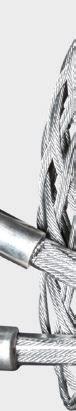
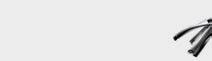
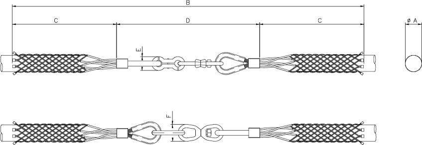
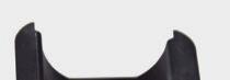
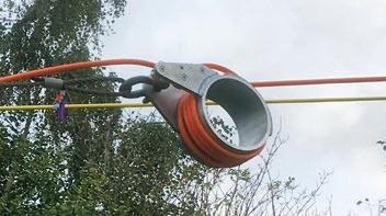
The Slingco Hydraulic Hose Harness limits the whip or ‘travel’ of a pressurized hose in the event of it becoming detached from its fitting.
Helps prevent injury to operators and damage to equipment near a hose failure
Ideal for use in Oil and Gas applications, mining and manufacturing for pressurized fluid and air hoses
Addresses both health and safety concerns and potential financial and legal ramifications

The damage caused by a violently whipping hose, especially one operating under high pressure, can pose severe health and safety concerns - not to mention financial and legal ramifications - for any company. The Slingco Hydraulic Hose Harness (H3) addresses this concern by limiting the whip or ‘travel’ of the pressurized hose if it breaks free from its hose fitting.
FEATURES AND BENEFITS


Designed to prevent whipping in the event of a pressurized hose becoming detached from the fitting


Helps prevent injury to operators and damage to equipment near a hose failure
Ideal for use in Oil and Gas applications, mining and manufacturing for pressurized fluid and air hoses


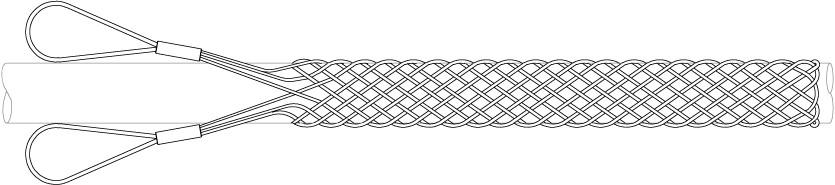
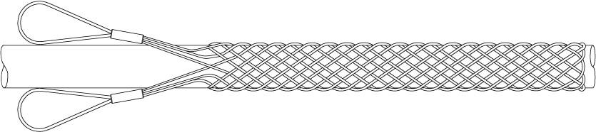
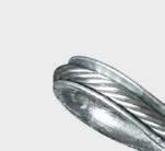
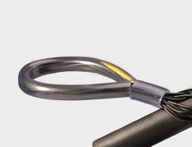
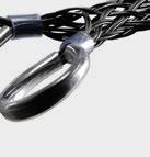
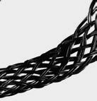
Double eye, double weave mesh construction, with reinforced thimble eyes
High strength galvanized steel


Note: all proper health and safety procedures must be carried out in addition to the use of an H3 Harness.
TAKE CONTROL WITH SLINGCO’S HYDRAULIC HOSE HARNESS

A VIOLENTLY WHIPPING HOSE CAN POSE A SERIOUS THREAT TO SAFETY & EQUIPMENT, AND CAUSE SERIOUS FINANCIAL AND LEGAL PROBLEMS


Aramid fibre grips with protective UV coating
Non-conductive, non-metallic, non-magnetic

Resistant to chemicals and corrosion
Ideal for use in water, fibre optic applications, offshore and for a multitude of uses in the electrical industry
Lightweight and easy to install
Excellent weight-to-break ratio


Available as single eye, double eye and offset eye


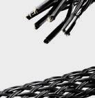
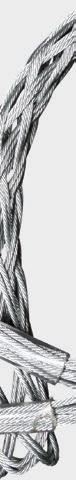
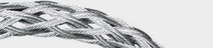
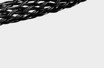
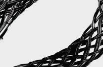
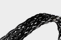
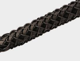
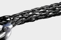
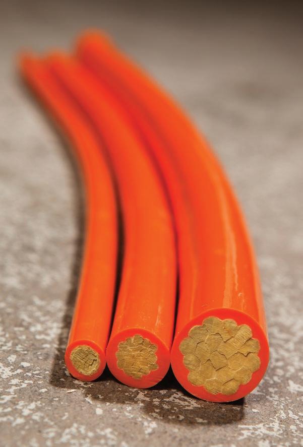
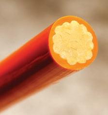
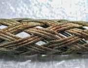
Slingco non-conductive (Aramid) cable pulling grips are ideal for fibre optic applications, offshore and for a multitude of uses in the electrical industry.
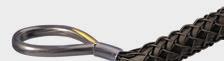

With dramatically improved weight to break ratio, these pulling grips are made of a high-strength, non-metallic aramid fibre, with a UV protective coating.
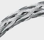
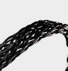
Suitable for pulling both single cable and cable bundles, these woven mesh grips offer a non-metallic alternative to steel. Non-metallic material is easy to work with even without gloves.

Available in a range of sizes in single, double and offset eye, the smaller sized grips have a single weave lattice and the larger ones a double weave lattice.
SINGLE EYE DOUBLE WEAVE NON-METALLIC GRIP

ZCS10231.25 - 1.5030 - 40246009,8604,470
ZCS10241.50 - 2.0040 - 502460011,8805,390
ZCS11792.00 - 2.5050 - 652460015,9007,210
ZCS11802.50 - 3.0065 - 802460015,9007,210
ZCS11813.00 - 4.0080 - 1003794015,9007,210
ZCS40794.00 - 5.00102 - 1271203,04815,9007,210
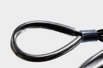
ND – NON-METALLIC (ARAMID) DOUBLE EYE GRIP
Slingco Part No Range Lattice Length Approx. Break Load


DOUBLE EYE SINGLE WEAVE NON-METALLIC GRIP
ZCS11480.38 - 0.7510 - 20246002,4601,115
ZCS11760.75 - 1.2520 - 30246003,5801,620
ZCS29221.00 - 1.5025 - 40246003,5801,620
ZCS11771.25 - 1.5030 - 40246004,9202,230
ZCS11781.50
ZCS11821.25 - 1.5030 - 40246009,8604,470
ZCS11831.50 - 2.0040 - 502460011,8805,390
ZCS11842.00 - 2.5050 - 652460015,9007,210
ZCS11852.50 - 3.0065 - 802460015,9007,210
ZCS11863.00 - 4.0080 - 1003280015,9007,210
ZCS38134.00 - 5.00102 - 12760.61,54015,9007,210
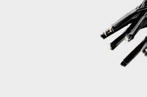
NO – NON-METALLIC (ARAMID) OFFSET EYE GRIP
SINGLE OFFSET EYE SINGLE WEAVE NON-METALLIC GRIP
ZCS28100.38 - 0.7510 - 20246002,4601,115

ZCS28110.75 - 1.2520 - 30246003,5801,620
ZCS29211.00 - 1.5025 - 40246003,5801,620
ZCS28121.25 - 1.5030 - 40246004,9202,230
ZCS28131.50 - 2.0040 - 50246005,8202,640
SINGLE OFFSET EYE DOUBLE WEAVE NON-METALLIC GRIP
ZCS28141.25 - 1.5030 - 40246009,8604,470
ZCS28151.50 - 2.0040 - 502460011,8805,390


ZCS28162.00 - 2.5050 - 652460015,9007,210
ZCS28172.50 - 3.0065 - 802460015,9007,210
ZCS28183.00 - 4.0080 - 1003486015,9007,210

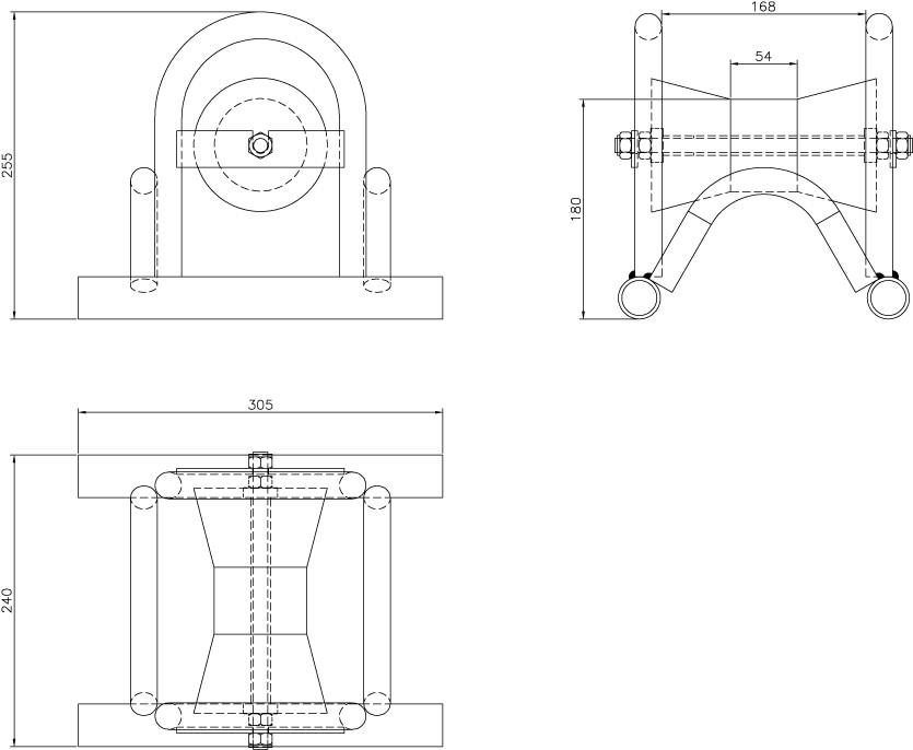
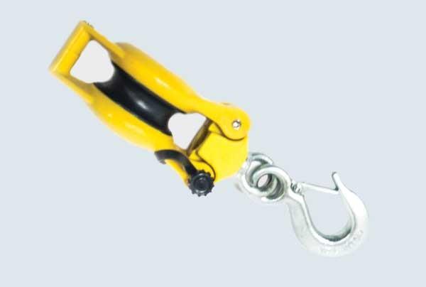

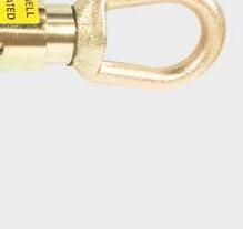
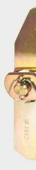
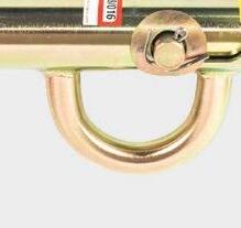
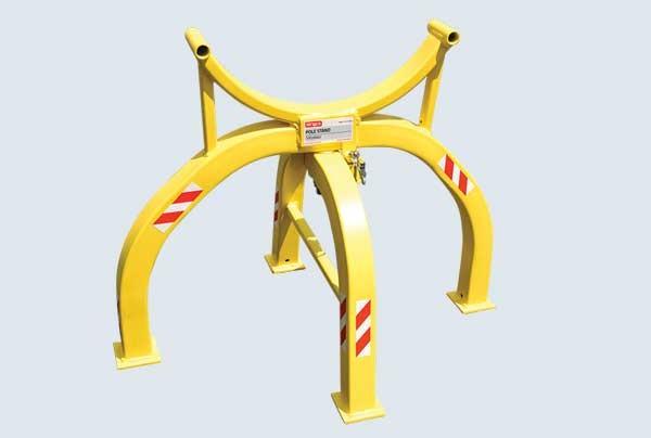
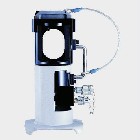
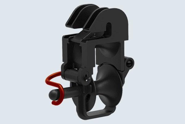
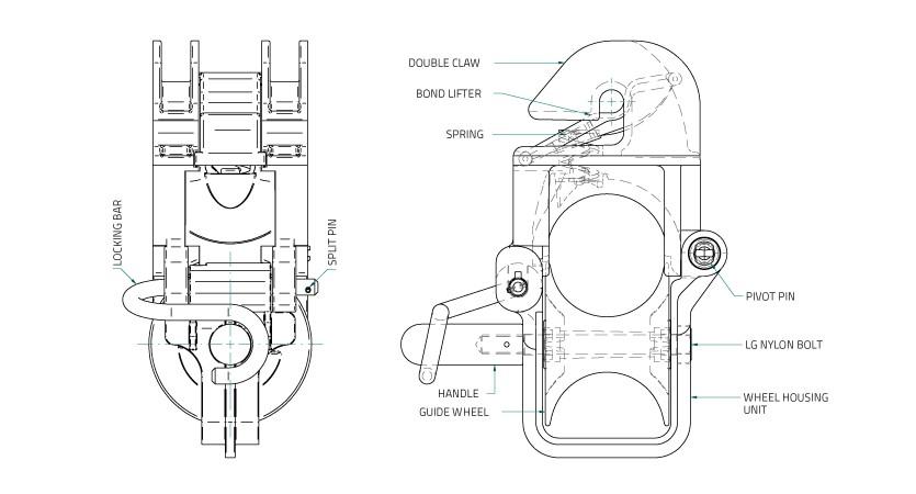
Makes handling large cable reels quick and easy, on-site or in warehouses.

Rugged construction to lift and upend reels
Easy rotation to unroll cable Counterweighted bottom arm for easy insertion in reel
Side lifting eye allows reels to be put into a rolling or non-rolling position
Repair kits available

The Slingco Reel Lifter is a high capacity, compact unit that allows users in the utility construction industry to safely load, transport, and dispense wire and/or cable on-site. It is also used in many industrial applications to make moving and relocating reels in a warehouse easy. Now a task that normally used a team of three or four people can be done with just one, allowing the crew to operate more efficiently!
Factory repair kits with extension springs, cable assemblies and all necessary pins for replacement of the interior cable system. ZLD097081,360 kg (3,000 lb) factory repair kit. Suitable for ZLD08729.
kg (5,000 lb) factory repair kit. Suitable for ZLD09186.
kg (12,000 lb) factory repair kit. Suitable for ZLD10807.
Distributed in New Zealand by: TransNet NZ Limited 78 Cryers Road, East Tamaki, Auckland, 2013

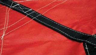
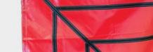
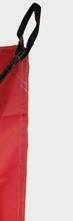
Heavy-duty webbing and lifting loops
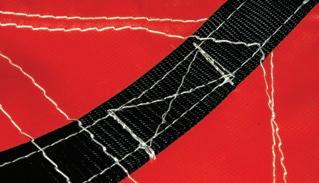

Double stitched for reinforcement and durability
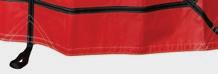


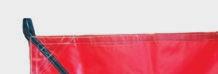
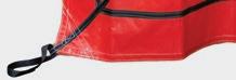
Simply clean, dry, store, and re-use!
Compact enough to store on truck when folded
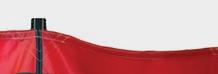
Slingco’s range of heavy-duty, re-usable dirt tarps have been created with safety in mind. Keeping workers out of awkward, injury-prone positions is better for their longterm health and the company’s bottom line. Dirt tarps have become a must-have product at utility construction sites. You can find Slingco Dirt Tarps being used at pole change-outs, transformer terminations, pedestals, as well as underground gas, telephone, and other underground utility applications.
In fact, with the ability to move crushed rock, sand, dirt, wet cement, dig spoils, and other contaminated soil, there are few reasons NOT to have a Slingco Dirt Tarp on the project!
 1
2 3 EASY AS 1-2-3!
1
2 3
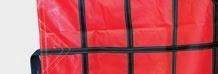
Collect site waste on flat dirt tarp (black nylon webbing facing down) Gather tarp loops for easy lifting Release loops for simple disposal
1
2 3 EASY AS 1-2-3!
1
2 3
Collect site waste on flat dirt tarp (black nylon webbing facing down) Gather tarp loops for easy lifting Release loops for simple disposal


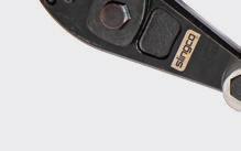

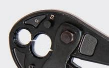
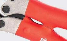
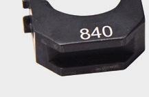
Slingco’s Mechanical Crimping Tools have been created to complete the variety of utility distribution service connections that need to be made on the line, pole, and home. Our crimping tools have been designed to provide reliable crimps installing full-tension or non-tension connectors.
Slingco’s Mechanical Crimping Tool’s ‘D3’ groove allows ‘W’ style die inserts for installing taps, splices, and terminal connectors. The ‘W’ die inserts lock securely and easily into place with the positive lock, spring-loaded die buttons. Slingco also offers a Mechanical Crimping Tool that accepts Kearney type dies.
Our Mechanical Crimping Tools also have ergonomic handles for comfortable use and maximum leverage when making critical connections.

‘D3’ groove allows ‘W’ style die inserts for installing taps, splices, and terminal connectors
Tool accepts Kearney type dies also available from Slingco
Ergonomic handles for comfortable use and maximum leverage


Slingco


available
See reverse for replacement die sets


Accepts Burndy L & Alcoa 6000 Series dies

Steel Carrying Case

Includes Ground Stand
Lifting eye for hoist work
For Crimping ACSR and ACAR transmission & distribution cables


Slingco’s Hydraulic Crimping Tools are designed to crimp sleeves and lugs on ACSR and ACAR transmission & distribution cables using dies that meet the standards of the utility industry. Our crimping tools are ideal for use in constructing substations & transmission lines.
The Single-Acting Crimping Tool uses hydraulic pressure to advance the ram into position, and an internal spring to return the ram to the original position. The Double-Acting Crimping Tool advances & returns the ram using hydraulic pressure alone, eliminating the possibility of the ram sticking or becoming jammed.
Our Hydraulic Crimping Tools (60-ton only) come in a steel carrying case, and are lightweight & portable. They accept Slingco S60 Dies, or any shell-type dies used with Alcoa or Burndy 60-ton crimping tools.
See reverse for replacement die sets
DIE SETS FOR 60-TON HYDRAULIC CRIMPING
DIE SETS FOR 100-TON HYDRAULIC CRIMPING


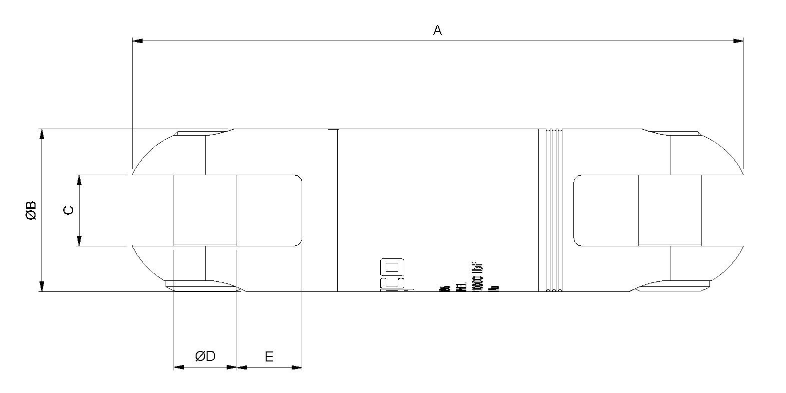
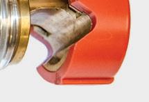
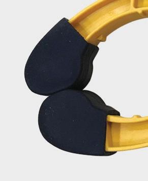
Slingco’s Jumper Clamps are used as a part of jumper cable assemblies to bypass work areas when equipment is under repair or being upgraded.
Jumper clamps are lightweight and impact resistant making them incredibly durable.
We make inspection of the cable, ferrule, and clamp simple and easy via the transparent clamp body.


The jaw of the Slingco Jumper Clamp and floating ring contact is made from a copper-based alloy.
NOTE: Slingco Jumper Clamps are sold individually. Slingco Jumper Clamps meet ASTM F2321 standard.
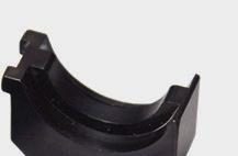
Used to hold insulating blankets and other types of rubber coverups in place, the Slingco Blanket Clamp Pin is constructed of ultraviolet stabilized fiberglass reinforced polymer.
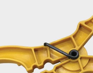
Extra holes in the center of the body are used to grip conductors and prevent linehose from sliding. Holes have also been placed in the handles to enable attachment of warnings, tags, and/or flags.
The handles of the pin are shaped to engage with the end ferrule of a clampstick (shotgun stick).


Distributed in New Zealand by: TransNet NZ Limited 78 Cryers Road, East Tamaki, Auckland, 2013

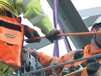
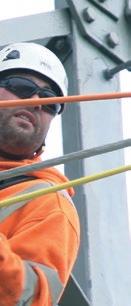

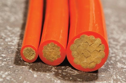
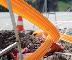
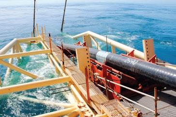
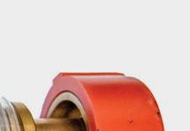
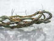
Roblon HVPR was initially designed for live-line stringing using the cradle-block method, but its excellent dielectric properties enable it to be used as helicopter longlines, guy lines for transmission towers and short-haul lines for work in energised electrical environments, and other applications.
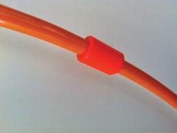
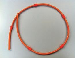
Roblon HVPR is a dielectric rope used for stringing and service operations, for installing OPGW, and similar operations. The rope is torque balanced and lightweight.
Roblon HVPR is manufactured from high performance aramid fibres with a thermoplastic polyurethane (TPU) coating. Roblon HVPR is available in four dimensions as standard (if other types are required, please contact us).
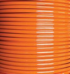
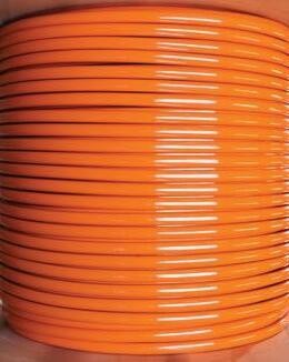
Colour: Default colour is bright orange for maximum visibility. Over time, the colour will change to yellow due to exposure to UV irradiation. The colour change is normal, and does not affect mechanical or electrical properties of the rope.
Minimum bending diameter
Static load 10 x diameter
Dynamic load 23 x Diameter
2.APPROVALS / CERTIFICATION:
Approvals / Certification
Certification Certified according to IEC 62192
Approval All dimensions are approved for live-line work up to 800kV r.m.s.
Slingco provides all products with a one-year warranty with regards to manufacturing defects, material quality, and workmanship. Slingco does not assume any liability for the use of the product or any losses resulting thereof, unless caused by product manufacturing defects or negligence of Slingco.
The rope must be stored in a dry and climate-controlled location, at 20-30˚C and max. 40% RH when not in use. These conditions may require sealing and/or dehumidification. Do not store in direct sunlight.
During transport and use, the rope should be kept in a sealed container with moisture absorbing crystals added, to the extent possible.
HVPR should be handled with care at all times in order to prevent damage to the thermoplastic coating. The rope must be kept clean and dry. Avoid laying the rope on the ground. If this cannot be avoided, the rope must be cleaned from mud and dirt as described in section 7. Avoid stepping on or placing heavy loads or sharp edges on the rope. Placing the rope over a sharp edge may damage the rope, and bending the rope more than the recommended minimum bend radius may affect strength and decrease the lifetime of the rope.
For use in rainy or moist conditions, careful consideration must be given to reduce any possible risk of current running through water film build-up on the rope. Mud and dirt will also increase risk.
The rope is approved for AC applications only and should not be used in a live-line DC environment. The rope may not be tied in a knot. Tying a knot will significantly reduce rope strength.
Small amounts of moisture may permeate the rope when used outside of climate-controlled areas for extended periods of time. After use, the rope should be returned to climate-controlled storage and remain there until next use. Electrical testing should be performed on return to storage. The test should be stopped immediately if leak current at any time exceeds acceptable levels.
Continued testing may damage the rope. In case electrical testing indicates moisture permeation, the rope should remain in specified climatic conditions, and electrical testing should be performed
weekly until passed. A single failed test on a rope that has been outside of climate-controlled condition is not grounds for rope retirement. Renewed electrical testing should be performed immediately before next use.
6. INSPECTION
The rope should be inspected visually prior to and after each use. Inspection after use is easily done when winding the rope onto the drum. Any damage, especially if fibres are visible, must be repaired immediately as specified in section 9.
7. TEST
Electrical testing should be an integral part of handling procedures as specified in section 5, and should as a minimum be performed before leaving the warehouse, and on return. Testing should be done according to the instructions provided in IEC 62192 clause 5.
8. PULLING METHODS
Local regulations, applicable protocols, and regulations imposed by the cable/wire manufacturer must be observed at all times. Consult the documentation for the cable/wire to be strung before planning stringing operations.
9. RECOMMENDED END FITTINGS
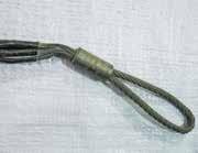
Method 1: Spliced eyes with thimble. The eyes can be used to couple any hook, shackle, or similar to the rope. Splicing has the same, or higher, MBL as the rope itself, and does not impose any limitations on pulling force. The length of the splice is not part of the certification, and should be handled as if conductive.
Method 2: Cable pulling grip
The cable pulling grip should be a highly flexible, overhead type, suitable for the diameter of the rope. Observe the recommended pulling force for the grip.
Double bearing swivels should be installed at both ends of the rope to avoid rotation. Open rope ends should be capped.
9.1
It is recommended to use clamps designed for insulated cables. Any clamps used on HVPR should have rubberised jaws. The clamped length along the rope depends on the projected pulling force. For pulling forces up to 1,000 kg (10kN), the clamped length should be at least 90 mm. Ensure that the pulling of the clamp does not create sharp bends, and that the clamp has no sharp edges that may damage the rope.
10. CLEANING
The rope surface must be kept clean. Any dirt on the surface, especially if combined with water, induces a risk of current running on the surface.
1. Clean the rope with water (use a brush if very dirty)
2. When the rope is fully dry, apply a coating of silicone or Teflon spray.
The spray treatment will make the rope run smoothly and will reduce the risk of water film building on the surface in wet conditions, inducing a risk of current running on the surface.
11.REPAIRS
Roblon has developed a proprietary method for repairing small cuts in the rope. Workers doing repairs or splices must have completed a training course overseen by Roblon, and hold a training certificate. In case of large and open cuts, or any damage affecting the fiber core, the damaged part of the rope must be cut away, and the rope reassembled by approved methods by a certificate-holding worker.
12.LIFETIME
Ropes wear out with use. The more severe the usage, the greater the wear. It is often not possible to detect wear on a rope by visible signs alone. Therefore it is recommended that the rope user keeps a usage log and determines a retirement criteria for ropes in their application, ensuring timely retirement according to local standards. The life expectancy/shelf life of the rope is expected to be 5-7 years depending upon storage conditions
13.DISPOSAL AND RECYCLING
The rope should be disposed of by incineration.
14.OPTIONAL
Ferrules can be moulded onto the rope as carrier. Dimensions and distance between the ferrules can be adjusted to meet any demand.
17.PACKING INFORMATION
Length of plain rope on standard reels:
15.MARKING
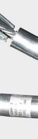
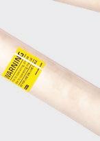
For easy identification, all ropes are marked with a label including product code, description of material, manufacturer, production year and batch number. Apart from this, it is possible to add the customer’s article no./order no., SWL from customer or other relevant information. All markings according to the requirements of IEC 62192.
16.TEST
All Roblon ropes are supplied with a standard Certificate of Conformity (CoC) indicating batch number, diameter and breaking strength.
An IEC 62192 test report for the electrical properties and a certificate of conformity for the specific batch can be supplied against additional costs. If required, please ask for a quotation for third party testing.
*The above lengths are for guidance only and may vary.
Reel sizes (all dimensions in mm):
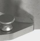
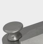
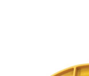
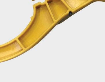
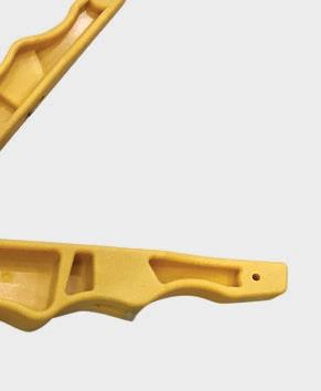
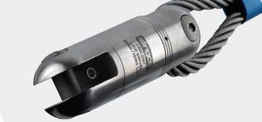
The Bollard Clamp is an easy to use tensioning device that can be used without risk of damage to the tensioned rope. This is a major advantage over standard types of gripping devices, which could potentially crush or compress the rope or its outer coating.
Installation of the Bollard Clamp is simple, requiring no tools, and the device can be fitted anywhere along the length of the rope using a spring-loaded rope captivation lever. One installed, the clamp utilises the friction created over a large area of the rope to enable the required tension to the specified WLL.
WLLProof loadMBLMaterialWeightBarrel diameter Rope suitability
17kN25.5kN51kNAluminium (6082/1050) 3 kg200mm12-15mm


Tension without damage to rope, outer coating or underlying layers


Secures the rope up to 3x WLL
Weighs only 3kg
Suitable for ropes
12-15mm diameter
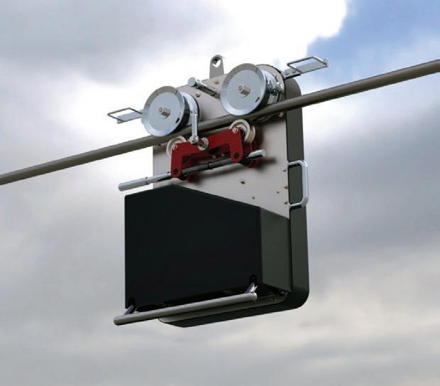
Figures given above are indicative only. Nominal figures/actuals are as per datasheet with tolerances of +/-5%. Datasheets available on request.Tractive effort 40kg @ 30° on Ø20mm conductor *
Automatic soft start - 4 kph with a run time 120 minutes from fully charged battery
2 driven rubber tyred wheels via a compact 18V – 12Ah battery
2.4GHz radio remote control 500m range
Operates on conductors/ropes ranging from Ø 14 – 55mm
Smooth transition over mid-span joints/connectors
Bi-directional travel with enclosed motor and drive units
Designated lifting point
Fully recoverable at both ends
* Tractive effort will be increased on larger diameter conductors
Slingco’s Multi-Function Cable Robot is a remotely operated, motorised aluminium chassis tug unit for the purpose of changing out de-energised overhead power cables or ground wires. The compact unit is powered using a rechargeable li-ion battery
which makes for quick onsite changeover in remote areas and designed to be used with conductor replacement systems and inspection devices. The unit comes complete with a standard recovery device.
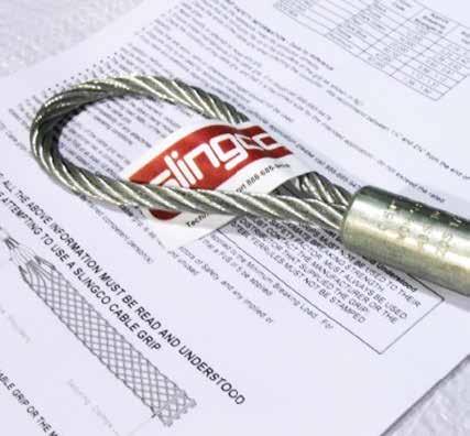


Safety is our primary concern. The products that we manufacture are safety critical and must be used by competent trained personnel. It is essential to choose the right cable grip for the job.

Inspecting a cable grip is not an exact science. There are a number of variables that can weaken a cable grip that are not immediately obvious on visual inspection. This is why we work to Factors of Safety. It is important to know the difference between Working Load and Approximate Break Load, and how to use the Factor of Safety to calculate the Working Load Limit for the cable grip that will be utilized.
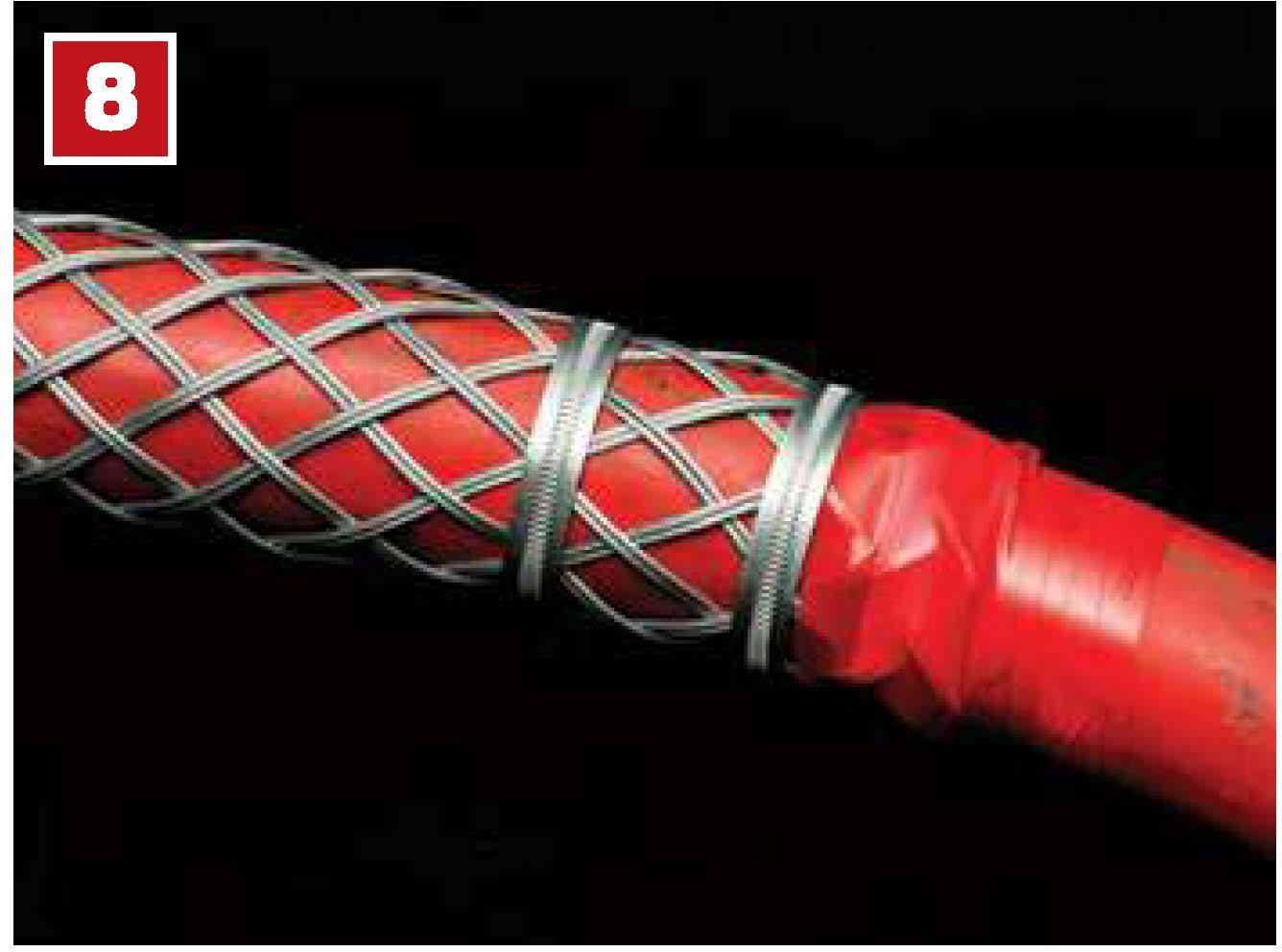
To maximize grip performance, we highly recommend utilizing banding on the ends of cable grips, as shown in the figure below.
• Overhead Pulling - 5 : 1
• Underground Pulling - 3 : 1
• Cable Supporting - 10 : 1
* General guideance only. Adhere to any existing company or industry safety guidelines if applicable.
The Working Load Limit (WLL), sometimes also known as the safety working load, is the mass that the equipment being used can safely hold, pull, or lower without breaking. In short, it’s the maximum load that can be applied to the product safely when in general service.
The Approximate Break Load (ABL) is the load at which a new grip can be reasonably expected to break. This is measured on a straight line pull only, as side pulling, or angular loads, will produce different results.
The Working Load is calculated by dividing the Approximate Break Load (ABL) by the Factor of Safety (FoS). No component in the system should exceed the working load for the cable grip.
The Factor of Safety (FoS) is the “extra” coverage of the breaking load over the over the working load expected. Factor of Safety is often noted as “X to 1” or “X:1”. The Factor of Safety accomodates normal spikes in load tension that may occur when under load.
This guide shows the proper usage, maintenance, and inspection of cable grips to ensure you achieve safe pulling operations, maximum grips strength, and grip longevity.
When you are inspecting a cable grip, it is critical to be able to identify damage or potential trouble spots. The following are some of the types of damage you should be aware of prior to beginning a pulling project with your cable grips. If these are observed, replacement of grip should be considered.
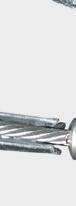
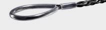
The eye of the cable grip is very important. If any damage is found, replace grip immediately. Causes of eye damage include:
• Pulling loads at an angle as opposed to straight line pulling
• Misuse and wear from excessive use
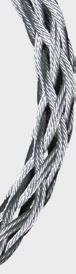
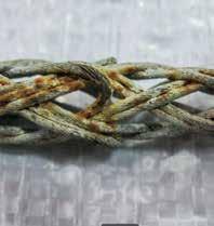
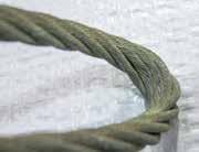
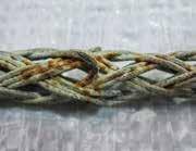
Rust will weaken the strands of wire that make up the cable grip. If excessive rust is identified, replace grip. Causes of rust are:
• Grips left in moist conditions or stored damp after water exposure
• Water with high salinity content will cause rusting more rapidly
The most important factor when using a cable grip to pull wire is to eliminate torsion, or twisting of the cable grip assembly. It is important, when stringing high tension wires for electrical transmission and distribution, to use the proper components to eliminate torsion.
If wires are likely to develop torsion during a pull, line pulling swivels enable the torque to be released, which otherwise could cause damage to the wire or grip.
Advantages of Slingco Swivels include:
• Reduce torsion strain
• Are quality tested and inspected
• Come in bull-nose or rounded style
• Can be matched-up with Slingco’s heavy duty grips
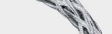
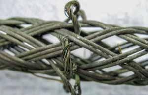
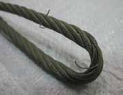
Frayed wires cause the cable grip to weaken significantly. The more wires damaged, the weaker the grip. Causes of fraying are:
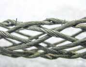
• Excessive abrasion while cable is being pulled
• Becoming stuck or snagging during a pulling operation
Bent and broken wires have the same effect as fraying and cause the cable grip to weaken significantly. Causes of this type of damage are :
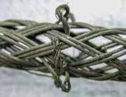
• Excessive abrasion while cable is being pulled
• General wear and tear over time
There are many factors that must be taken into account when assessing the suitability of a cable grip for a proposed application, and when trying to calculate the working load limit. These include:
• Size of cable grip in relation to size/shape of gripped object
• Stability of object(s) when gripped
• Grip surface of object(s)
• Resistive force of object(s)
• Anticipated path of movement, including possible obstructions
• Approximate breaking strength of the cable grip
• Condition of cable grip
• Suitability and compatibility of any attachments used
• Environment/operating conditions
• Persons at risk
If you have any questions regarding suitability for any particular application, please call teh distributor who supplied the cable grip, or our in-house Technical Department.
Please note: Slingco cable grips must be double steel banded securely before being pulled.
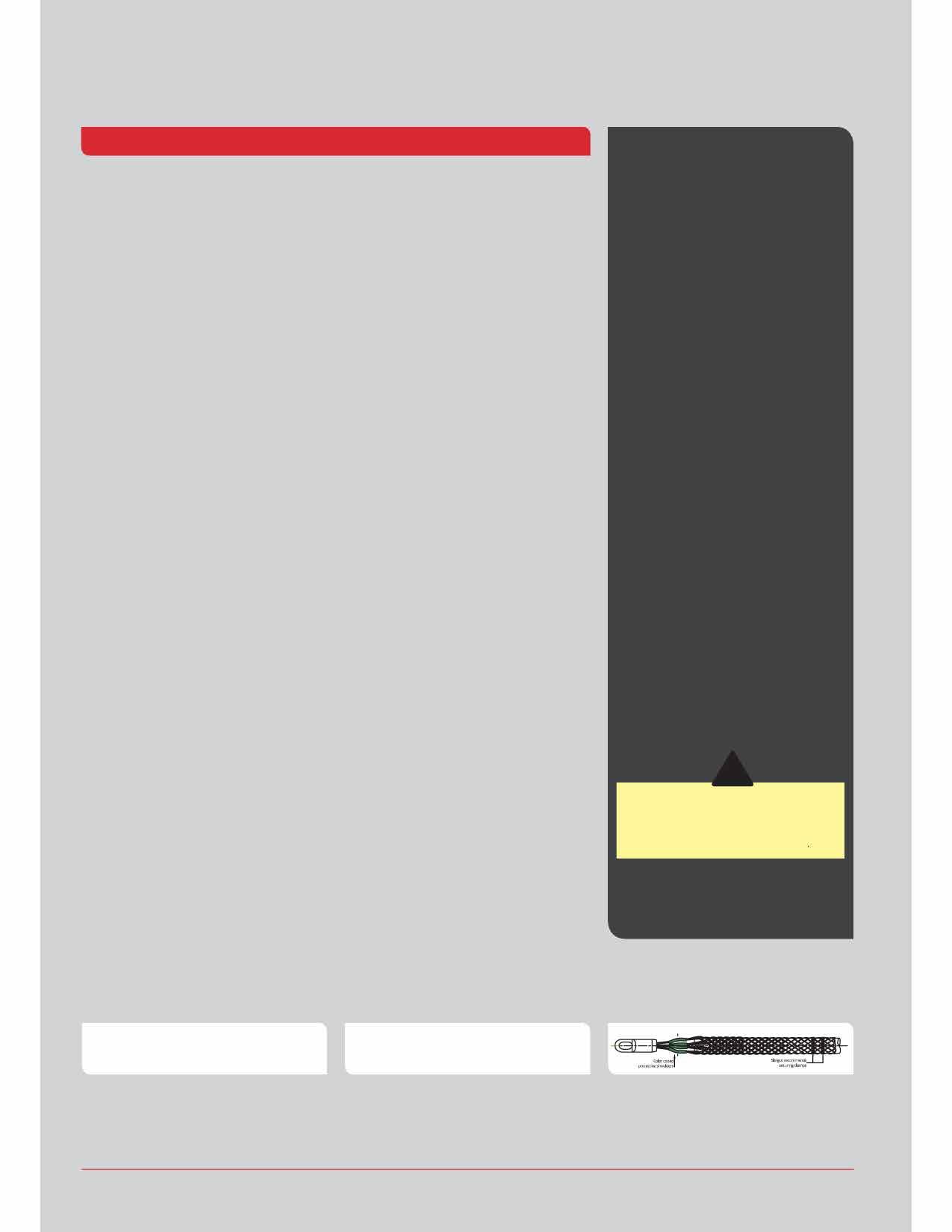
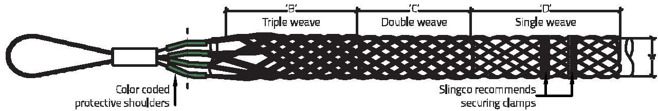
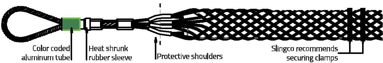
• Ensure that the cable grip mesh fits the cable correctly
• Ensure that the cable fits up to the mid-point of the protective shoulder
• Clamp the ends of the cable grip when attaching the cable. We recommend between 1.25” and 2.25” from the end of the cable grip. SECURE CLAMPING MUST BE USED ON SLINGCO CABLE GRIPS
• Never modify or attempt to repair any cable grip
• Ensure proper maintenance of the cable grip. If in doubt, call 888-685-9478
• Check the condition of the cable grip, and that it is the correct size for the intended application - do not exceed the rated capacity
• Cable grips that are worn, bent, or otherwise damaged should not be used
• Cable grips are only to be used for temporary installations
• Pulling devices should only be attached via the pulling eye
• Cable grips must only be fitted and used by trained competent person(s)
SLINGCO CABLE GRIPS MUST NOT BE USED TO THEIR APPROXIMATE BREAKING STRENGTH. A SENSIBLE SAFETY FACTOR MUST ALWAYS BE USED. IF IN DOUBT CONTACT THE MANUFACTURER OR DISTRIBUTOR THAT SUPPLIED THE CABLE GRIP.
There aremany factors that must betaken into account whenassessingthe suitability of a cable grip for a proposed application and trying to calculate a safe working load. These include:
■ Size of cable grip in relation to size/shape of gripped object(s)
■ Stability of object(s) when gripped
■ Grip surface of object(s)
■ Resistive force of object(s)
■ Anticipated path of movement, including possible obstructions
■ Approximate breaking strengthof the cable grip
■ Condition of cable grip
■ Suitability and compatibility of any attachments used
■ Environment / operating conditions
■ Persons at risk
If you have any questions regarding suitability for any particular application please call the distributor who supplied the cable grip or our in-houseTechnical Department.
Please note:Slingco cable grips must be double steel banded securely before being pulled.
Lattice dimensions shownare as fitted to a nominal diameter of cableand prior 'free length' may beslightly longer thanstated.
This is the calculated average based on actual testing done by Slingco. Approximate break loads are quoted asa guide only.
Application load is normally calculated to be reduced by at least a factor of 5x the Approximate break load. Due to the wide variety of application parameters, the end user must apply a sensible safety factor to suit the safety requirements for the conditions of use.
The Safe Working Load (SWL) of a Slingco cable grip will depend on the Factor of Safety (FOS) applied to the Minimum Breaking Load.
Where the operational risk is considered to be normal, it is recommended that a FOS of 5 be applied, for a high risk operationa FOS of at least 10 should be considered. It is impossible to catalogue or guarantee a safety factor that will apply for all applications.
Approximate Break Loads stated on any certification, the recommended Factors of Safety, andany implied orstatedfitnessfor purpose, are all only applicable when the cable grip isas new and unused.
A 20% variance in break loads must be allowed for whenselectinga cable grip; a suitable swivel must be used if there is 'twist' in the cable.
Torsionalstress must be dealt withwhen using grips for line pullsand wire splices. When twisting forcesare present use a swivel that rotates under load to release torsional stress.
■ Ensure that the cable grip mesh fits conductor correctly
■ Ensure that the conductor fits up to the mid-point of the protective shoulder
■ Clamp the ends of the cable grip when attaching the conductor. We recommend between 1¼" and 2¼" from the end of the cable grips
SECURE CLAMPING MUST BE USED ON SLINGCO CABLE GRIPS
■ Never modify or attempt to repair any grip
■ Ensure propermaintenanceof thecablegrip. If indoubtcall 01706 855558
■ Check the condition of the cable grip, and that it is the correct size for the intended application - do not exceed the rated capacity
■ Grips that are worn, bent or otherwise damagedshouldnot beused
■ Gripsare only to be used for temporary installations
■ Pulling devices should only be attached via the pulling eye
■ Cable grips must only be fitted and used by trained competent person(s)
If you have any questions regarding suitability for any particular application please call 01706 855558
Theconditionofthecablegripshouldalways becheckedpriortouse.Thecorrectsizeofgrip shouldalwaysbeusedfortheintendedapplication.Theratedcapacityofthegripshould neverbeexceeded.Gripsthatareworn,bent orotherwisedamagedshouldnotbeused.
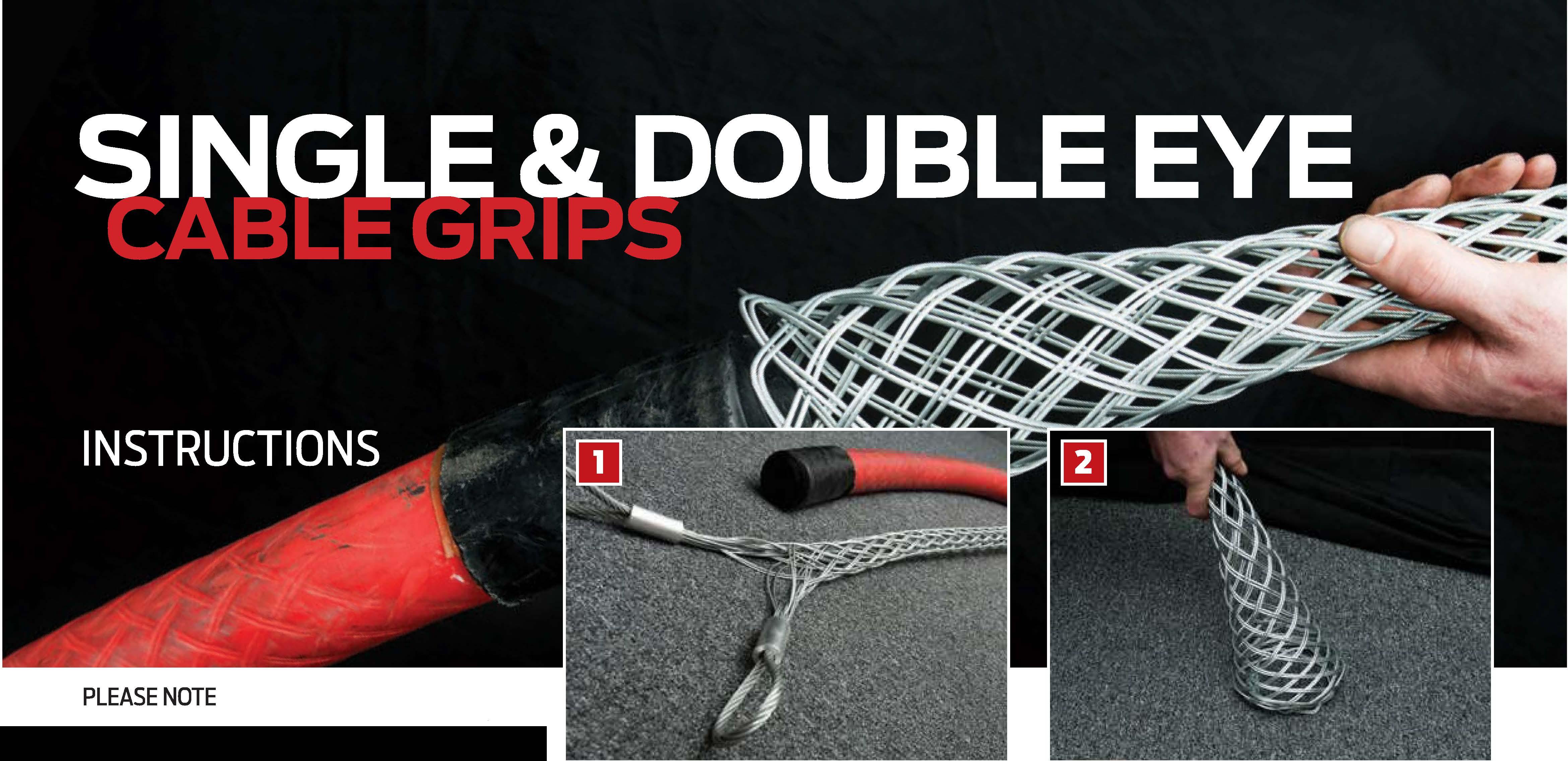
Select
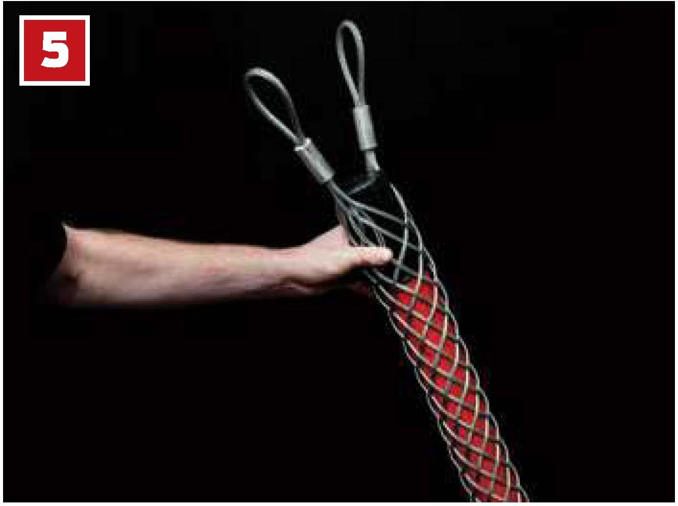
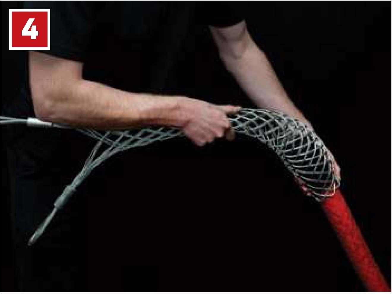
Priortouse,thelatticeattheendofthe gripneedstobewidened.Thiscanbeeasily achievedbypressingtheendofthegrip againstahardsurface,whichcausesthe latticetoexpand.
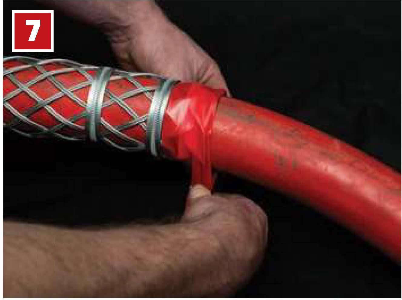
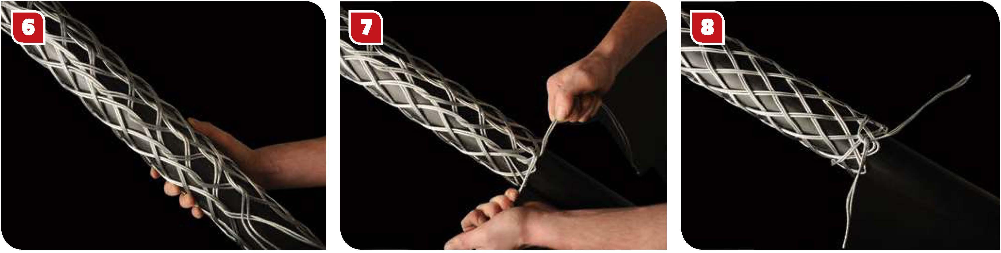
Oncethecablegripisinplaceontheconductor, twoclampsshouldbefittedtotheendofthe grip (asshown). Werecommendbetweenl ¼" (30mm)and2¼" (55mm)awayfromtheend ofthecablegrip.
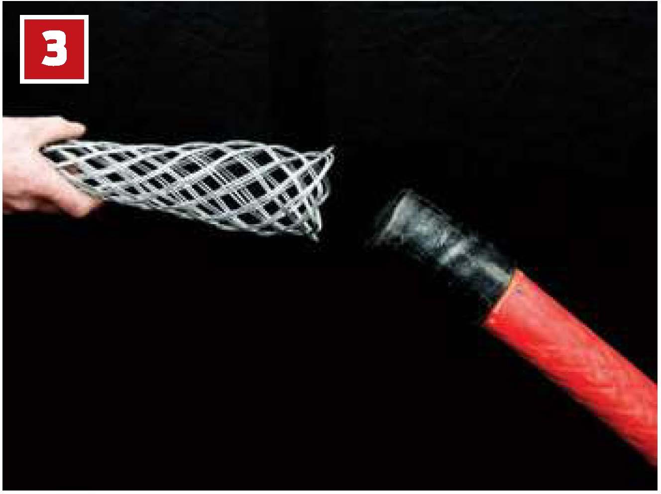
Thegripshouldthenbeplacedovertheendof theconductor... thecorrectgripforthediameterofthe conductor. ...andpushedovertheconductor. Tapeshouldthenwewoundaroundtheendof thecablegripfurthestawayfromtheeyeends Thegripthenneedstobepushedalongsothat allthelatticeisincontactwiththeconductor.
PLEASE NOTE: The imagesshown here use double weave cable grips. When lacing single weave cable grips please use single wire lace; use double-laced fordouble weave cable grips; anduse triple-laced for triple weavecablegrips.
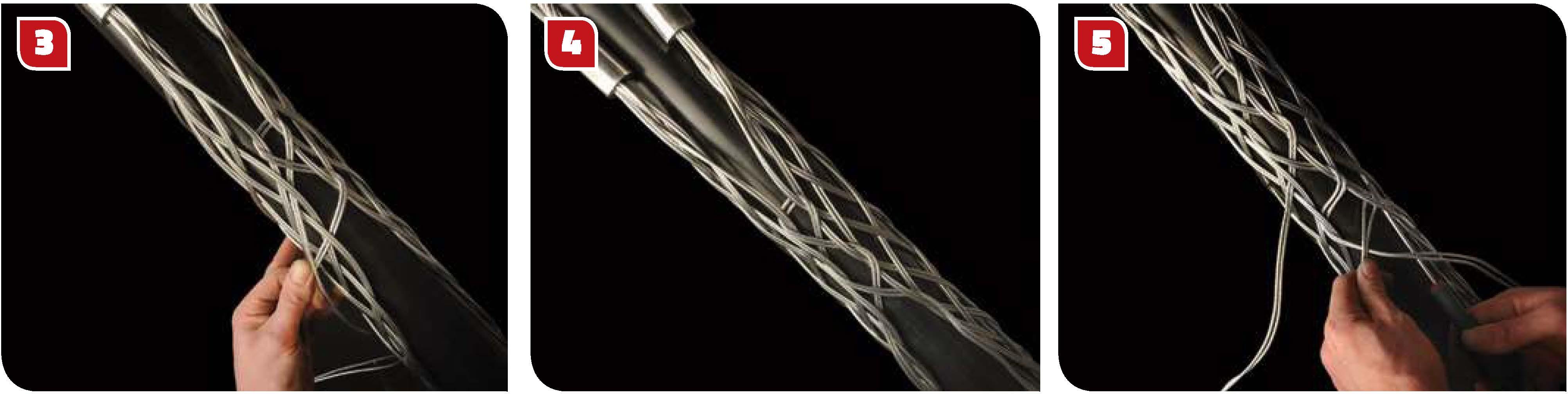
Don't pull the lace too tight at this stage. Leave a space between adjoining loops roughly equal to the width of one diamond of the mesh.
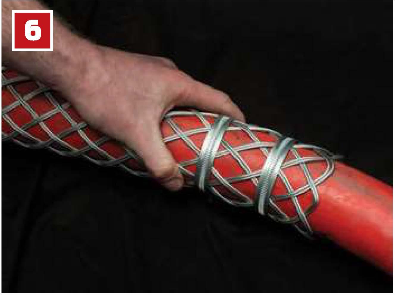
Continue down the length of the cable grip. Tryto maintain equal tension and equal spacing throughoutas this leads to a more stableand equal grip.
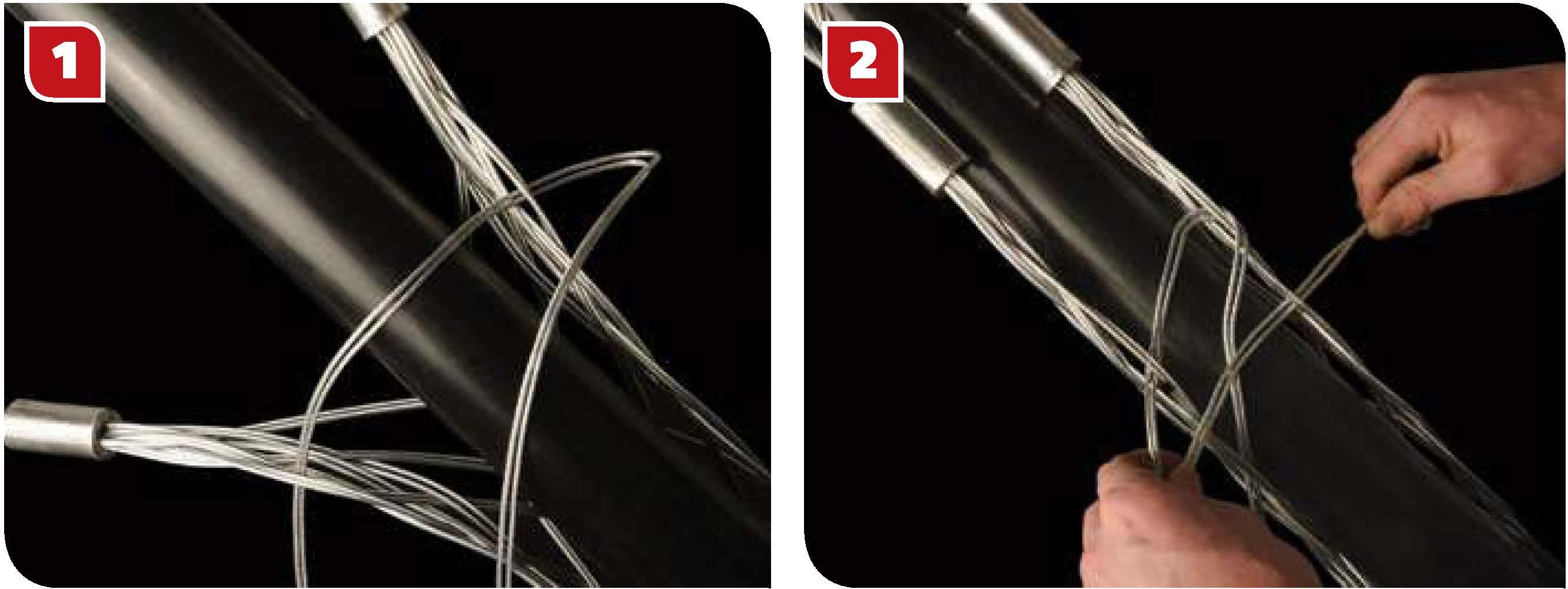
As you continue down the length, pull the open sides of the grip as wide apartas required.
Tryto achieve an even and neat lace-up as this assists with the strength of the grip when pulling.
Finally, tie the ends of the lace once or twice round the end of the cable grip twisting the ends together securely. Excess lace can be cut off.
Add any additional supportas requiredbanding is recommended. The Slingcocable grip is now ready to use.
Startthelacingfrom the 'eye' end or anchoring end of thecable grip.