General
Thissectioncontainsproceduresforadjustment,repair,andtroubleshootingoftheElectricPowerSteering(EPSIII)SystemandAdvancedPowerSteering (APS)System.Thesystemscontrolthesteermotor usedtoturnthemasterdriveunit.Thelifttruck steeringiscontrolledbyturningthemasterdrive unit.
EPSIII
EPSIIIisonlyapplicabletotheB174,E118,F118, andC174trucks.TherearethreetypesofEPS IIIsystemsavailable:thestandardsystem,called theReturn-to-Center(RTC)SteeringSystem,the optionalTachGeneratorSteering(TGS)System, andtheoptionalWireGuidanceSteeringSystem.
ThissectionpertainstotheRTCandTGSSystems only.
NOTE: ThismanualisNOTapplicabletolifttrucks withtheoptionalWireGuidanceSteeringSystem. Seethesection WireGuidance-Description 2200 SRM421forchecksandadjustmentsandthesection WireGuidance-Repair 2200SRM422forrepairs tothesteeringsystemoftrucksequippedwiththe WireGuidanceSteeringSystem.
APS
APSisonlyapplicabletotheG118andD174trucks. Therearetwosteeringinputdevicesusedwith theAPS:thestandardsystem,calledtheMultiturnSteering(MTS)Systemandtheoptional Return-to-Center(RTC)System.
Description
EPSIII
TheEPSSystemiscomprisedofthefollowingcomponents:
• Steeringhandle(RTCSystem)orsteeringwheel (TGSSystem)
• Commandpotentiometer(RTCSystem)orthetach generator(TGSSystem)
• Feedbackpotentiometer
• Steersystemwireharness
• ElectronicControlModule(ECM)
• Lifttruckbattery
• Steermotor
• Steeringsprocketandchain
WARNING
TheMasterDriveUnit(MDU)willautomaticallycenterwhenthekeyisON.Keephands, arms,andotherappendagesandtoolsclear.
TheRTCSystemhasasteeringhandlethatreturns tothecenterpositionwhenreleased.Thehandle moves100degreeseachsideofcenterforthefull rangeofsteeringcontrol.TheTGSSystemhasa steeringwheelcoupledtoabelt-driventachgenerator.ThesteeringwheeldoesNOTautomaticallyreturntothecenterposition.
Thesteeringhandleandcommandpotentiometerfor theRTCSystemarelocatedintheoperator’scompartment.Similarly,thesteeringwheelandtach
generatorfortheTGSsystemarelocatedintheoperator’scompartment.TheECMandsteermotorare inthemotorcompartmentbesidethemasterdrive unit.Thefeedbackpotentiometerisconnectedtothe steermotorbelowthesteersprocket.Thesteering chainconnectsthesteersprocketatthegearmotor tothesprocketofthemasterdriveunit.TheECMis alsolocatedinthesteermotorcompartment.
Thecommandpotentiometerattachedtothesteering handleprovidesasignaltotheECMcorresponding totheoperatorinput.Similarly,thetachgenerator coupledtothesteeringwheelontheoptionalTGS systemprovidesasignaltotheECMcorresponding totheoperatorinput.TheECMprocessesthesignal todeterminethesteerangleselectedbytheoperator. Thefeedbackpotentiometerisconnectedtothesteer motor.Thefeedbackpotentiometerprovidesasignal totheECMthatcorrespondstothepositionofthe masterdriveunit.
Thesignalfromthecommandpotentiometer(ortach generator)andthesignalfromthefeedbackpotentiometeraresentsimultaneouslytotheECM.Ifthe masterdriveunitisnotattheoperator-selectedangle,theECMprovideselectricaloutputtothesteer motor.
Thesteermotoriscoupledtothemasterdriveunit withasprocketandchain.Theelectricaloutput tothesteermotorcausesthemotortorotatethe
sprocketandchainandturnthemasterdriveunit. Asthemasterdriveunitapproachestheselected angle,thesignalfromthefeedbackpotentiometer changestoinstructtheECMtoslowandthenstop therotationofthesteermotor.
APSSYSTEM
TheAPSSystemiscomprisedofthefollowingcomponents:
• APScontroller
• Steeringhandle(RTC)orsteeringwheel(MTS) mechanisms
• Steeringencoderforbothsystems
• Steeringproximityswitch(RTConly)
• MDUcenteringproximityswitch(MTSandRTC)
• Steermotorwithbuilt-inpositionencoder
• Steeringsprocketandchainorgear
TheMTSSystemhasasteeringwheelthatdoesNOT automaticallyreturntothecenterposition.Ithasno stops.
TheRTCSystemhasasteeringhandlethatreturns tothecenterpositionwhenreleased.Thehandle moves100degreeseachsideofcenterforthefull rangeofsteeringcontrol.
ThesteeringwheelandencoderfortheMTSSystem arelocatedintheoperator’scompartment.The steeringhandle,steeringproximityswitch,and steeringencoderfortheRTCSystemarelocatedin
GENERAL
WARNING
theoperator ’scompartment.TheAPScontroller, steermotor,andtheMDUcenteringproximity switchareinthemotorcompartmentbesidethe masterdriveunit.
Thesteeringencoderisattachedtothesteering wheel,whichprovidesasignaltotheMasterControl Unit(MCU)correspondingtotheoperatorinput. Similarly,thesteeringhandleontheoptionalRTC systemprovidesasignaltotheMCUcorresponding totheoperatorinput.TheMCUprocessesthesignal tothesteerangleselectedbytheoperator,and steeringcommandsaresenttotheAPScontroller viatheCANbuscommunicationwires.
IftheMDUisnotattheoperator-selectedangle,the APSprovideselectricaloutputtothesteermotor.
Thesteermotoriscoupledtothemasterdriveunit withasprocketandchainoragear.Thesteering chainconnectsthesteersprocketatthegearmotor tothesprocketofthemasterdriveunit.Theelectricaloutputtothesteermotorcausesthemotorto rotatethesprocketandchainorpiniongearandturn themasterdriveunit.Onlifttrucksthathavegear steering,thepiniongearonthesteeringactuatordirectlydrivestheringgearonthemasterdriveunit. Asthemasterdriveunitapproachestheselectedangle,thesignalfromthesteeringencoderchangesto instructtheAPScontrollertoslowandthenstopthe rotationofthesteermotor.
ChecksandAdjustments
notmovethelifttruckandcauseapersonalinjury.
Donotoperatealifttruckthatneedsadjustmentsorrepairs.Reporttheneedforadjustmentsorrepairsimmediately.Ifadjustment orrepairisnecessary,putaDONOTOPERATEtagintheoperator ’sarea.Removethekey fromthekeyswitch.
WARNING
Someofthechecksandadjustmentsaredone withthebatteryconnected.Neverhaveany metalonyourfingers,arms,orneck.During somechecksoradjustments,theoperatormust movethelifttruck.Thepersondoingtheadjustmentsmustmaketheadjustmentswiththe systemenergized.Makesuretheoperatordoes
Donotmakeadjustmentstoaproperlyoperating steersystem.
CHECKS,EPSIII
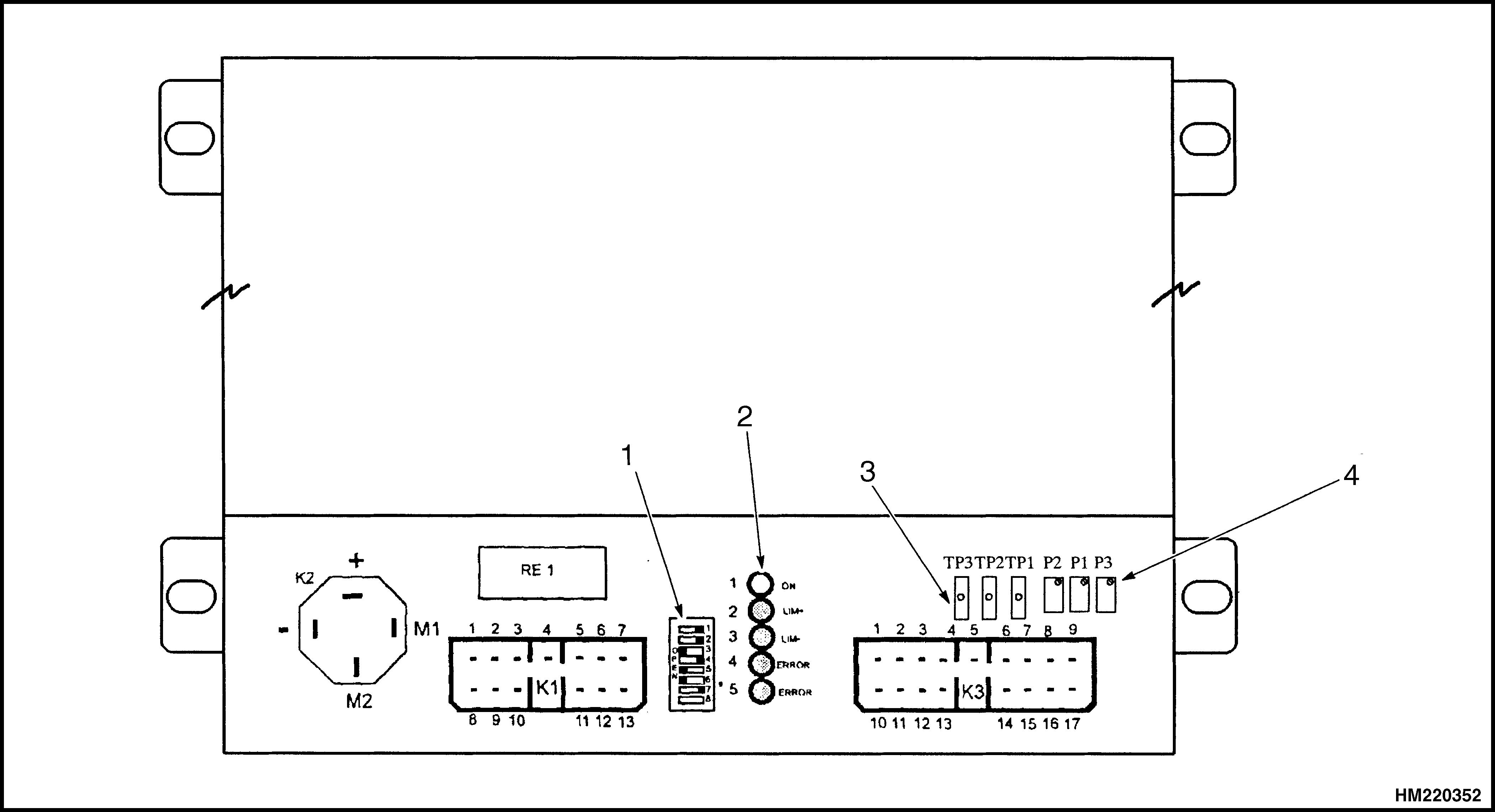
Threetestpointsareprovidedforadjustmentofthe ECM.TP1isthefeedbackpotentiometerinputadjustedbyP2.TP2isthecommandpotentiometerinputadjustedbyP1.TP3istheanalogandlogiccommon.Light-EmittingDiodes(LEDs)1through5,locatedontheECMcircuitboard,areusedtoindicate steersystemfaults.
Dipswitches,EPSIII
NOTE: Thedipswitchesarefactory-setandshould notneedtobeadjusted.
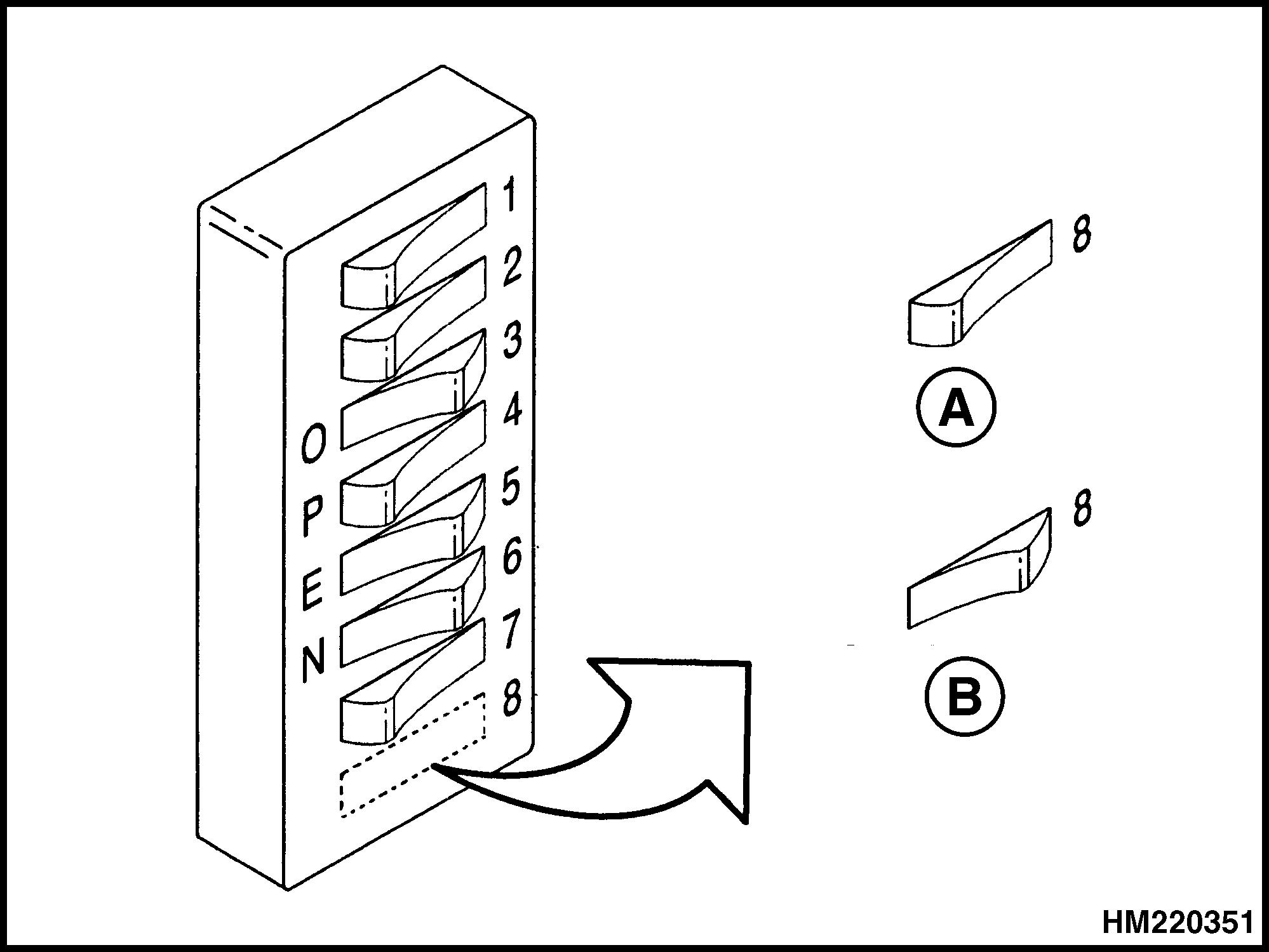
IftheECMisreplaced,orthesettingsofthedipswitchesareinadvertentlychanged,refertoFigure1 tosetthepositionofthedipswitchestothefactory settings.
OntrucksequippedwiththeoptionalTGSSystem, anadjustmentcanbemadetothesettingsofdipswitches5,6,and7toalterthesensitivityofthe tachgeneratorinputscaling,ifdesired.RefertoTach GeneratorSteeringSystem,EPSIII,SensitivityAdjustment,EPSIIIintheAdjustmentssectionfollowing.
Table1.LEDIndicators(Continued)
LED4off,LED5on Errorincontrolleror motorcircuit
LED4on,LED5on Errorincontroller
LED4off,LED5off, andLED1on(withno soundfrommotor)
Supplycontactor faultorvoltageon emergencybrake coil(thecontroller mustremainofffora minimumof2seconds beforeanewstartup toavoidanerror condition)
CheckSteeringSystemforCorrect Operation,EPSIII
TheECMcheckincludeschecksforthecommandpotentiometerandthefeedbackpotentiometer.
1. Openthemotorcompartmentdoor.Movethe keyswitchtothe ON positionandpushthefoot switch.Makesurethebatteryhasacorrected specificgravityofatleast1.250.
A. SETSWITCH8FORRTCSTEER
B. SETSWITCH8FORTACHSTEER
Figure1.Dipswitches-FactorySetting
LEDIndicators,EPSIII
TheECMcontinuouslymonitorsthesteeringsystem. ProblemsdetectedbytheECMareindicatedby5 LEDs.RefertoFigure2andTable1.Thevehicles equippedwithelectricsteeringsystemsaredesigned tostopautomaticallywhenafaultoccurs.Thebrake relay,locatedintheECM,appliesthebraketostop thevehicleifafaultconditionisdetected.
Table1.LEDIndicators
LED1on(green)(with motorclickingsound)
Controlleractive
LED2on(red) Leftlimitreached
LED3on(red) Rightlimitreached
LED4on,LED5off Errorinsensorcircuit
2. Checkthesystemforcorrectoperation,movethe steeringhandleorsteeringwheelfromafullleft turnpositiontoafullrightturnposition.The masterdriveunitshouldmove85to95degrees ineachdirectionfromstraighttravel.
3. Ifthemasterdriveunitmoveslessthan90degrees(±5degrees)ineitherdirection,thesteeringisincorrectlyadjustedormayhaveamechanicalproblem.RefertoAdjustments.
4. Checkthatthemasterdriveunitmovesthrough thefullrangeofrotationin5secondsorless.The lifttruckmustbeonsmoothconcretewithafully chargedbatteryandnoload.
5. Ifthemasterdriveunitrequiresgreaterthan 5secondstomovethroughthefullrangeofrotation,checkforamechanicalproblemordefective ECM.
CheckSlowTravelSpeed,EPSIII
NOTE: Theslowtravelspeedischeckedduringthe adjustmentprocedure.RefertoAdjustments.
1.DIPSWITCHES
2.LEDS
CheckHighLiftTractionShutoff,EPSIII
1. Instructtheoperatortoraisetheplatformabove 3810mm(150in.).
2. Thetractionsystemshould NOT operatewith theoperatorplatformabove3810mm(150in.) unlessthetruckisequippedwiththehighlift travel-enableoption.Notethatthestandard travelcut-outfortheE/F118is5384.8mm (212in.).Iftheunitissoequipped,checkthat thetractionsystemoperatesnormallyEXCEPT whenthesteeringissetfor10degreesormore fromcenterandtheoperatorplatformisabove 3810mm(150in.).Ifthesteeringissetformore than10degreesandtheoperatorplatformis above3810mm(150in.),thetractionsystem shouldNOToperate.
CHECKS,APS
Therearenoadjustmentsforthe1243Controller ModuleforAPSSystem.
Dipswitches,APS
TheirarenodipswitchesontheAPSSystem.
3.TESTPOINTS
4.POTENTIOMETERS
LEDIndicators,APS
TheirarenoLEDindicatorsontheAPSSystem.
ADJUSTMENTS
General
NOTE: ThismanualisNOTapplicabletolifttrucks withtheoptionalWireGuidanceSteeringSystem. See WireGuidance-DescriptionEPSIII 2200 SRM421or WireGuidance-DescriptionAPS 2200SRM957forchecksandadjustmentstothe WireGuidanceSteeringSystem.
NOTE: Donotmakeadjustmentstoaproperlyoperatingsteeringsystem.Thefollowingadjustments mustbedoneintheorderspecified.Donotmovethe steeringwheelorhandleafterithasbeenaccurately centeredunlessinstructedtomoveitinthefollowing procedures.
NOTE: Thesteermotorhasnointernalserviceable parts.Donotdisassemblethesteermotor.
NOTE: Thesteermotorgearboxdoesnothaveany serviceableparts,nordoesthegearboxoilneedtobe checked,refilled,orreplaced.
Makesurethebatteryhasacorrectedspecificgravity ofatleast1.250.Movethelifttrucktoanopenarea whereitcanbedriveninastraightlineforadistance ofatleast9m(30ft).
SteerMotorWithSteeringChain Replacement,EPSIII
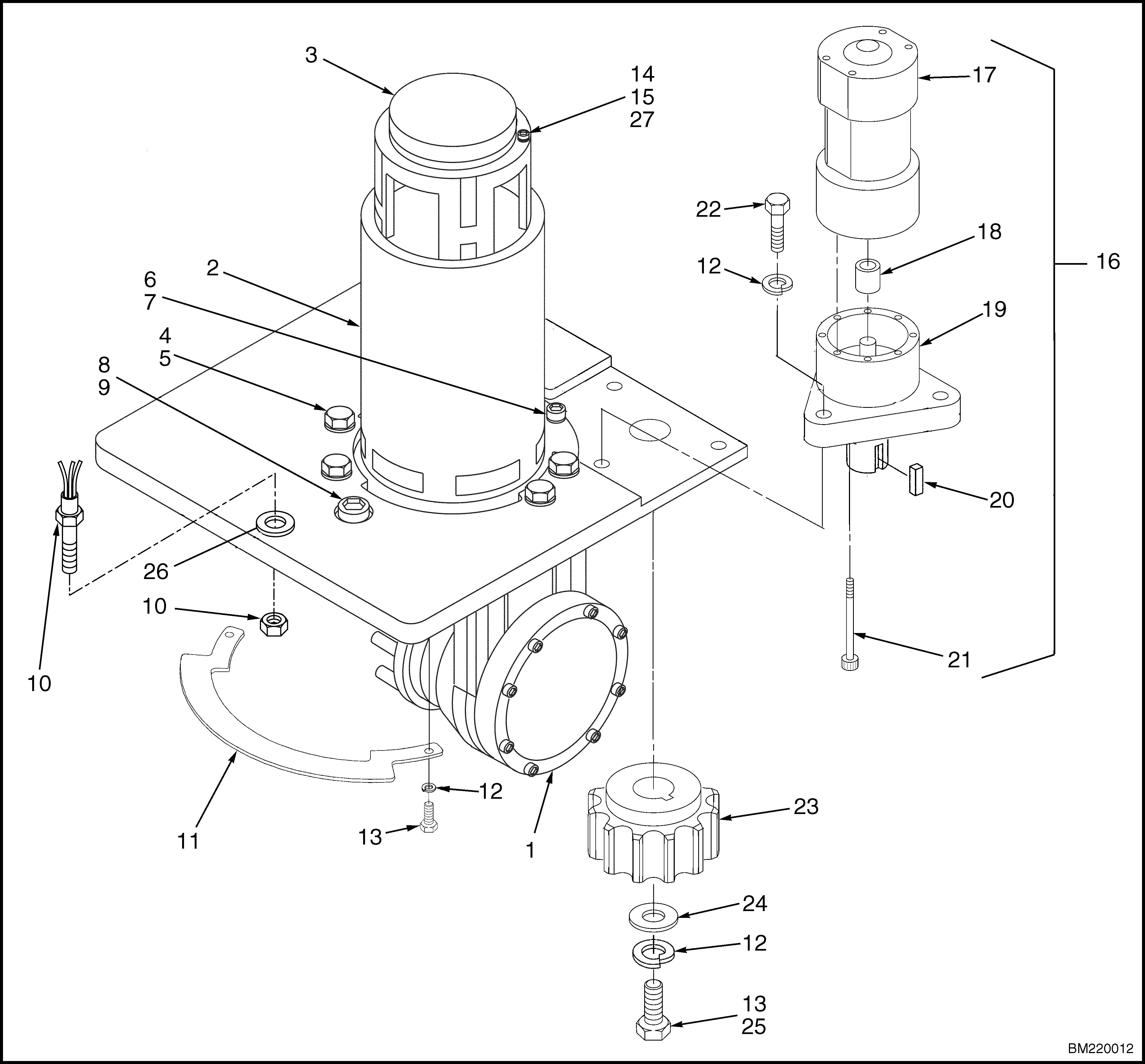
RefertoFigure5andFigure6forthefollowinginstructions.
1. Turnkeyswitch OFF,disconnectbattery,and openthemotorcompartmentdoor.
2. Holdthesteermotorassemblyandremovethe capscrews,nuts,andwashersthatfastenthemotorassemblytotheframe.
3. Carefullytipthetopoftheassemblyawayfrom thepaneltoremovethemotorfromthetruck. Removethesteeringchainfromthesprocket.
4. Removethesteeringchainfromthemasterdrive unitsprocketasrequiredbypullingthechain anchorpinsoutoftheholesinthesprocket. Cleanandlubricatethechainusingmultipurposegrease.
5. Makesurethemasterdriveunitisalignedfor straighttravel.Installthesteeringchainonthe masterdriveunitsprocket.Installthepinofthe chainanchorinthefirstholebeforetheaxlecenterline.
6. Installthenewmotorandsprocketassembly. Tightenthecapscrewsandnutsto31N•m (23lbfft).
SteerMotorWithSteeringGear
Replacement,APS
RefertoFigure7forthefollowinginstructions.
1. Turnkeyswitch OFF,disconnectbattery,and openthemotorcompartmentdoor.
2. Removethethreeboltsholdingthesteermotor assemblytotheframeandliftoutthesteermotor andpiniongear.
3. Installsteermotorontotheframebyaligning theteethofthepiniongearwiththeteethofthe steeringgearandinstallingthethreebolts.
NOTE: Therearenoadjustmentsbetweenthesteeringgearmotorandthesteeringgear.
4. Torquethethreeboltsholdingthesteermotorassemblytotheframeto23N•m(17lbfft).Lubricatethepiniongearandringgearsusingmultipurposegrease.
Return-to-CenterSteeringSystem
CommandPotentiometerAdjustment,EPSIII
WARNING
TheMDUwillautomaticallycenterwhenkeyis ON.Keephands,arms,andotherappendages andtoolsclear.
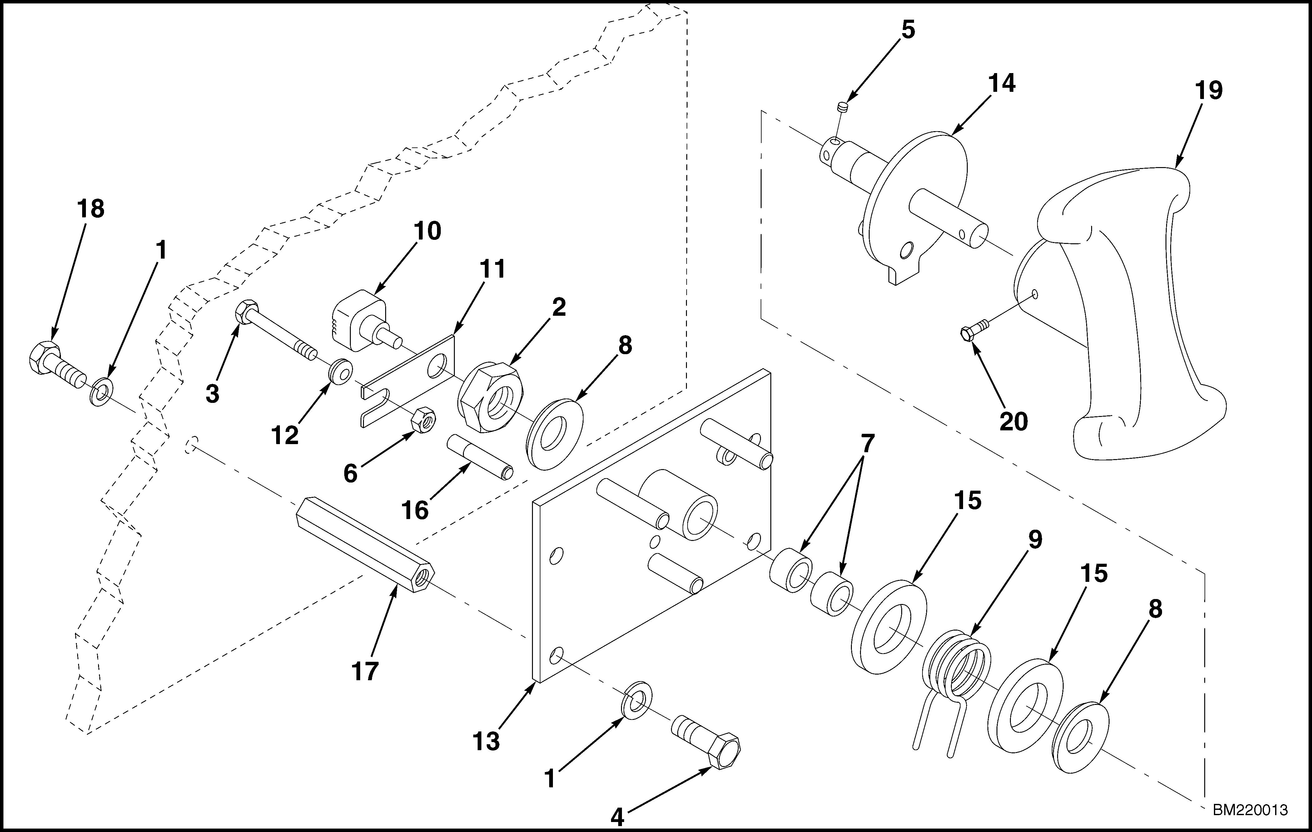
TheReturn-to-Center(RTC)commandpotentiometerislocatedatthesteeringmechanismintheinstrumentpanel.RefertoFigure3andFigure4.Removethescrewsatthetopoftheinstrumentpanel. Tiltthepaneltotheopen(down)positionforaccess tothepotentiometer.
1.RTCSTEERINGHANDLE
2.INSTRUMENTPANEL
3.COMMANDPOTENTIOMETER
4.RETAININGNUT
5.COWLCAPSCREWS
Figure3.Return-to-Center(RTC)Steering, EPSIII

1. Setthekeyswitchinthe OFF position.
2. Unplugtheconnectorfromthecommandpotentiometer.RefertoFigure3.
3. Useanohmmetertomeasuretheresistancebetweenwires19(black)and20(green).Measure theresistancebetweenwires20(green)and21 (white).
4. AdjustthecommandpotentiometeruntiltheresistancevaluesmeasuredinStep3areequal (+50ohms).Adjustthepotentiometerbylooseningtheretainingnutandmovingthepotentiometerbodytoattainthedesiredresistancereadings.Tightentheretainingnutwithoutmoving thepotentiometerbody.
5. AttachtheplugremovedinStep2tothecommandpotentiometer.
6. Setthekeyswitchtothe ON position.
7. MeasurethevoltageacrossTP3andTP2on theECMcircuitboardbyinsertingthenegative probeintoTP3andthepositiveprobeinTP2. RefertoFigure2.AdjustpotentiometerP1on theECMcircuitboardtoavalueof0VDC(+ 0.05VDC).
FeedbackPotentiometerAdjustment(Earlier ModelsOnly)
CAUTION
MakesuretheRTCcommandpotentiometer isproperlyadjustedbeforeadjustingthefeedbackpotentiometer.
1. Centerthedrivetireandsteerhandlefor straighttravel.Afterthedrivetireandhandle arecentered,donotadjustthesteerhandle againuntilspecificallyinstructedtodosointhis procedure.
2. RefertoFigure5andFigure6toidentifythe feedbackpotentiometer.Unplugtheconnector fromthefeedbackpotentiometer.
3. Measuretheresistancebetweenwires16and17. Measuretheresistancebetweenwires17and18.
4. AdjustthefeedbackpotentiometeruntiltheresistancevaluesmeasuredinStep3areequal (+50ohms).Adjustthepotentiometerbylooseningtheretainingnutandmovingthepotentiometerbodytoattainthedesiredresistancereadings.Tightentheretainingnutwithoutmoving thepotentiometerbody.
5. AttachtheplugremovedinStep2tothefeedback potentiometer.
6. Setthekeyswitchtothe ON position.
NOTE: Iftherearenosteeringchangeswithina 10-secondperiod,theECMremovespowertothe steermotor.Torestorepowertothesteermotor, steponthefootswitch.
7. MeasurethevoltageacrossTP3andTP1on theECMcircuitboardbyinsertingthenegative probeintoTP3andthepositiveprobeintoTP1. RefertoFigure2.EnsurethattheECMhas notremovedpowertothesteermotor.Adjust potentiometerP2ontheECMcircuitboardtoa valueof0VDC(+0.05VDC). 1.MOTOR 2.MOTORMOUNTINGBRACKET
3.CHAIN
4.SPROCKET
5.POTENTIOMETERMOUNTINGBRACKET
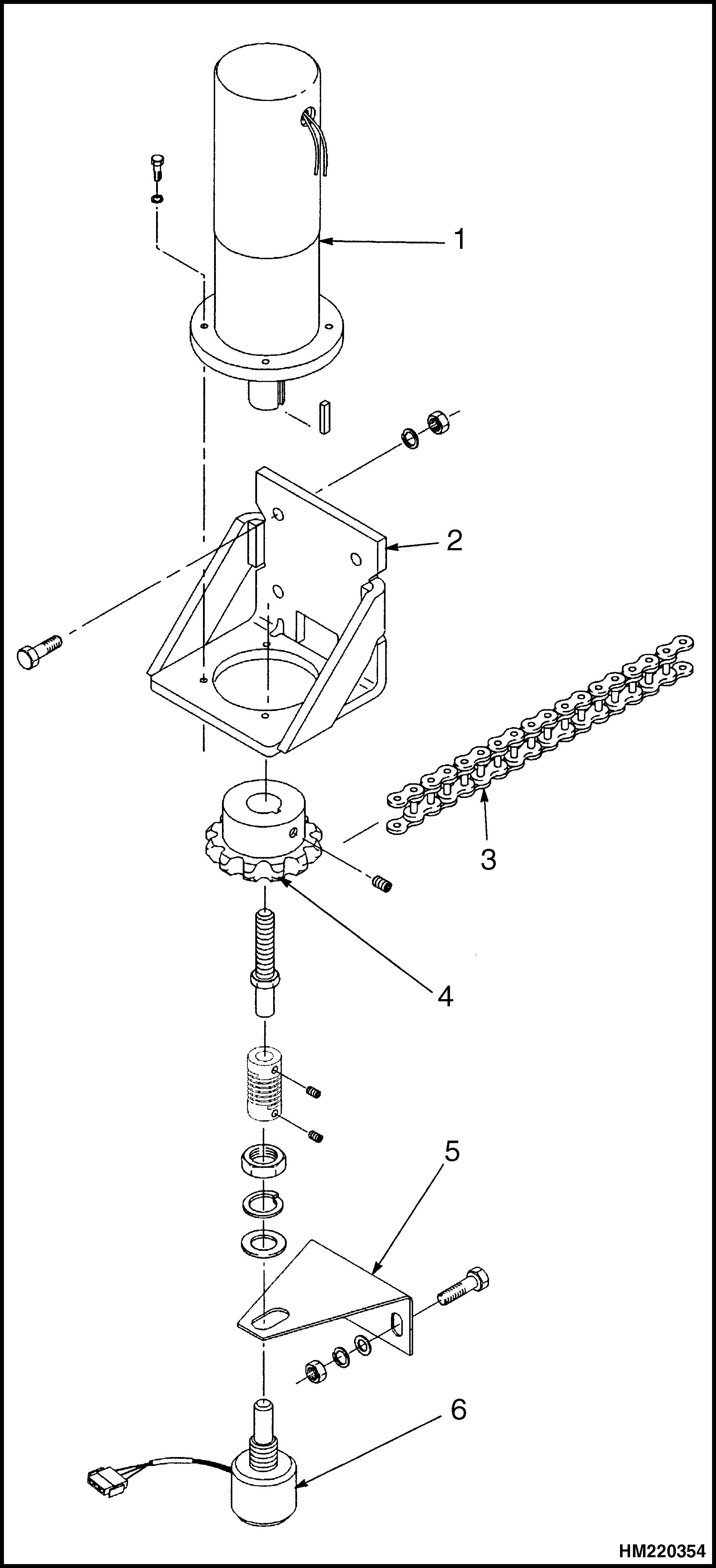
6.FEEDBACKPOTENTIOMETER
Figure5.MotorMountingAssembly(EPSIII)
Thank you very much foryourreading.Please Click Here Then Get MoreInformation.
NOTE: If there is no response to click on the link above, please download the PDF document first and then clickonit.

Duringthefollowingcheck,theoperatormust movethelifttruck.Usecautiontoavoidapersonalinjury.
8. Operatethelifttruckinastraightlineforatleast 9m(30ft)withouttouchingthesteerhandle.AdjustpotentiometerP2againasnecessarytoensurethelifttrucktravelsinastraightlinewithin 152mm(6in.)in9m(30ft).
9. Toverifythatthelifttruckistravelingina straightline,installapointeratthecenterof thefront(masterdriveunitend)ofthelifttruck. Makeamarkonthefloorunderthepointofthe pointer.
10. Operatethelifttruckstraightforward5m(16ft). Makeamarkonthefloorunderthepointofthe pointer.
11. Operatethelifttruckstraightforward5m(16ft) more.Makeanothermarkonthefloorunderthe pointofthepointer.
12. Drawastraightlinebetweenthefirstandlast marks.Thecentermarkmustbewithin76mm (3in.)oftheline.Ifthecentermarkiswithin thisspecification,P2iscorrectlyadjusted.Ifthe markis NOT withinthespecification,adjustP2 untilthetrialissuccessful.
TachGeneratorSteeringSystem,EPSIII
TachGeneratorAdjustment,EPSIII
Thetachgeneratorislocatedatthesteeringmechanismintheinstrumentpanel.Removethescrewsat thetopoftheinstrumentpanel.Tiltthepaneltothe open(down)positionforaccesstothetachgenerator.
Thetachgeneratordoesnotrequireadjustment. Checkthedrivebeltforproperalignmentandverify thatthebeltisnotexcessivelyworn.Replaceas required.
SensitivityAdjustment,EPSIII
WARNING
ChangingthesensitivitysettingoftheTGS Systemalterstheamountofoperatoreffort requiredtosteerthetruck.Notifyallaffected operatorsthatthetruckmaysteerdifferently beforeoperation.Usecautiontoavoidapersonalinjury.
ThesensitivityoftheTGSSystemisadjustedby changingthepositionofdipswitches5,6,and7.Do notchangeanyotherdipswitches.RefertoTable2.
Table2.SensitivityAdjustment
Switches5,6,and7 closed
Switches6and7closed, switch5open
Switches5and7closed, switch6open
Switch7closed, switches5and6open
Switches5 and6closed, switch7open
Switch6closed, switches5and7open
Switch5closed, switches6and7open
Switches 5,6,and7 open
MaximumSensitivity
(FactorySetting)
MinimumSensitivity
FeedbackPotentiometerAdjustment,EPSIII
1. Centerthedrivetireforstraighttravel.
2. RefertoFigure5toidentifythefeedbackpotentiometer.Unplugtheconnectorfromthefeedbackpotentiometer.
3. Measuretheresistancebetweenwires16and17. Measuretheresistancebetweenwires17and18.

4. AdjustthefeedbackpotentiometeruntiltheresistancevaluesmeasuredinStep3areequal (+50ohms).Adjustthepotentiometerbylooseningtheretainingnutandmovingthepotentiometerbodytoattainthedesiredresistancereadings.Tightentheretainingnutwithoutmoving thepotentiometerbody.
5. AttachtheplugremovedinStep2tothefeedback potentiometer.
6. Setthekeyswitchtothe ON position.
7. MeasurethevoltageacrossTP3andTP1on theECMcircuitboardbyinsertingthenegative probeintoTP3andthepositiveprobeinTP1. RefertoFigure2.AdjustpotentiometerP2on theECMcircuitboardtoavalueof0VDC(+0.05 VDC).
WARNING
Duringthefollowingcheck,theoperatormust movethelifttruck.Usecautiontoavoidinjury.
8. Operatethelifttruckinastraightlineforatleast 9m(30ft),makingcorrectionswiththesteering wheelasnecessarytokeepthetrucktravelingin astraightline.Attheendofthe9m(30ft),donot touchthesteeringwheel.Adjustpotentiometer P2againasdescribedinStep7.
9. Repeatthisprocedureaminimumofthreetimes toensureaccuratepotentiometeradjustment.
SlowTravelAdjustment,EPSIII
Thelifttruckisdesignedtobespeed-limitedabove specificmastheights.Proceedasfollows:
1. Makesurethebatteryhasacorrectedspecific gravityofatleast1.250.Makesurethatthelift truckhasbeenoperatedatfullspeedforapproximately10minutesbeforecheckingthespeed.
2. Movethelifttrucktoanareathatissmoothand levelforaminimumof30m(100ft).Referto Figure8.Putalineacrossthefloorat10m(33ft) andanotherlineacrossthefloorat20m(66ft)to dividetheareainthreeequalsections.Thefirst 10m(33ft)sectionisusedforacceleration,the middlesectionforthespeedmeasurement,and thelastsectionfordeceleration.
3. Raisetheoperatorplatformslightlyover610mm (24in.).
WARNING
Duringthefollowingcheck,theoperatormust movethelifttruck.Besureallpersonnelare clearofthetestingarea.Usecautiontoavoid injury.
4. Positionanassistanttothesideatthe10m (33ft)lineandanotherassistanttothesideat the20m(66ft)line.Operatethelifttruckat fullspeedthroughthetestareatodeterminethe elapsedtimebetweenthe10m(33ft)lineand the20m(66ft)line.Thelifttruck must travel atfullspeedthroughtheentirelengthofthe middle10m(33ft)sectiontoobtainaccurate data.
5. Ifthemeasuredelapsedtimeislessthan10seconds,adjustpotentiometerP3ontheECMcircuit boardcounterclockwisetoslowthetruckspeedto 3.5+0.3km/h(2.2+0.2mph).
6. Ifthemeasuredelapsedtimeismorethan10seconds,adjustpotentiometerP3ontheECMcircuit boardclockwisetoincreasethetruckspeedto3.5 +0.3km/h(2.2+0.2mph).
Return-to-CenterandMultiturnSystem, APS
EncoderReplacement,APS
1. Disconnectthebatteryconnector.
2. Removethescrewthatfastensthesteeringhandletotheshaftofthesteeringmechanism.Removethesteeringhandle(RTConly).
3. Removethescrewsatthetopoftheinstrument panelcovertogainaccesstotheinstrument panel.
4. Removethecapscrewsthatfastenthesteering mechanismbrackettothebackoftheinstrument panel.
5. Removethesetscrewthatfastenstheshaftofthe encodertothesteeringshaft.Removethecapscrewandnutthatfastenthebracketfortheencoder.Removethebracketandencoder.Remove theencoderfromthebracket.Labeltheencoder connectorforcorrectconnectionsduringinstallation.
6. Installthenewencoder,asrequired.Connectthe connectoroftheencoder.
7. Installthesteeringmechanismbrackettothe backoftheinstrumentpanel.
8. Connectthebatteryconnector.
9. Connectallwiresdisconnectedduringremoval.
10. Tightenthetwosetscrewsthatfastentheencodertothesteeringshaft.Oneofthesetscrews shouldbealignedwiththeflatareaontheencodershaft.
11. Closetheinstrumentpanelandtightenthe screws.Installthesteeringhandleontheshaft ofthesteeringmechanismandtightenthescrew.
SteeringChainAdjustment,EPSIII
1. Disconnectthebatteryconnector.Openthemotorcompartmentdoors.
2. Positionastraightedge(e.g.,athinpieceofrigid material)againstthesteeringchainbetweenthe sprockets.Makesurethechainistightonthe oppositesideofthesprockets.
3. Pushonthechainatapointapproximately halfwaybetweenthesprocketswithaforceof 9to12kg(20to26lb).Measuretheclearance betweenthestraightedgeandthechain.The clearanceshouldnotexceed3.3mm(0.13in.). RefertoFigure9.
4. Tightentheadjustmentnutatthemasterdrive unitsprockettoobtainamaximumclearanceof 3.3mm(0.13in.)betweenthechainandstraight edge.Do NOT tightenthechaintoaclearanceof lessthan1.3mm(0.05in.).
5. Closeandfastenthemotorcompartmentdoors.
Repairs
RTCSTEERINGSYSTEM,EPSIII
CommandPotentiometerReplacement, EPSIII
WARNING
TheMDUwillautomaticallycenterwhenkeyis ON.Keephands,arms,andotherappendages andtoolsclear.
1. Disconnectthebatteryconnector.
2. Removethescrewthatfastensthesteeringhandletotheshaftofthesteeringmechanism.Removethesteeringhandle.
3. Removethescrewsatthetopoftheinstrument panel.Tilttheinstrumentpaneltotheopenpositionforaccess.

4. Removethecapscrewsthatfastenthesteering mechanismbrackettothebackoftheinstrument panel.
5. Removethesetscrewthatfastenstheshaft ofthecommandpotentiometertothesteering shaft.Removethecapscrewandnutthatfasten thebracketforthecommandpotentiometer. Removethebracketandpotentiometer.Remove thepotentiometerfromthebracket.Labelthe potentiometerwiresforcorrectconnections duringinstallation.
6. Installthenewcommandpotentiometerasrequired.Connectthewiresofthecommandpotentiometer.
7. Installthesteeringmechanismbrackettothe backoftheinstrumentpanel.
8. Connectallwiresdisconnectedduringremoval.
