New Holland L213 Tier 3 Skid Steer Loader Service Repair Manual PIN NEM459110 and above

Page 1

Copyright © 2014 CNH Industrial America LLC. All Rights Reserved. SERVICE MANUAL L213 Tier 3 200 Series Skid Steer Loader PIN NEM459110 and above L216 Tier 4B (final) 200 Series Skid Steer Loader PIN NEM477964 and above Part number 47711677 1st editon English May 2014
SER VICE MANUAL L213 TIER 3 [NEM4591 - ] L216 TIER 4 [NEM477964 - ] 4771 1677 06/05/2014

Link Product / Engine

Product Market Product Engine L213 TIER 3 [NEM4591 - ] Europe N844L L216 TIER 4 [NEM477964 - ] Europe N844L T - F - 45SL 4771 1677 06/05/2014
Contents INTRODUCTION Engine . . . . . . . . . . . . . . . . . . . . . . . . . . . . . . . . . . . . . . . . . . . . . . . . . . . . . . . . . . . . . . . . . . . . . . . . . . . . . . . . . . . . . . . [10.001] Engine and crankcase . . . . . . . . . . . . . . . . . . . . . . . . . . . . . . . . . . . . . . . . . . . . . . . . . . . . . . . . . . . . . 10.1 [10.220] Throttle linkage . . . . . . . . . . . . . . . . . . . . . . . . . . . . . . . . . . . . . . . . . . . . . . . . . . . . . . . . . . . . . . . . . . . . . 10.2 [10.400] Engine cooling system . . . . . . . . . . . . . . . . . . . . . . . . . . . . . . . . . . . . . . . . . . . . . . . . . . . . . . . . . . . . . 10.3 [10.414] Fan and drive . . . . . . . . . . . . . . . . . . . . . . . . . . . . . . . . . . . . . . . . . . . . . . . . . . . . . . . . . . . . . . . . . . . . . . 10.4 [10.501] Exhaust Gas Recirculation (EGR) - Diesel Particulate Filter (DPF) exhaust treatment Front axle system . . . . . . . . . . . . . . . . . . . . . . . . . . . . . . . . . . . . . . . . . . . . . . . . . . . . . . . . . . . . . . . . . . . . . . . [25.450] Chain drive system . . . . . . . . . . . . . . . . . . . . . . . . . . . . . . . . . . . . . . . . . . . . . . . . . . . . . . . . . . . . . . . . . 25.1 Rear axle system . . . . . . . . . . . . . . . . . . . . . . . . . . . . . . . . . . . . . . . . . . . . . . . . . . . . . . . . . . . . . . . . . . . . . . . . Chain drive system Hydrostatic drive . . . . . . . . . . . . . . . . . . . . . . . . . . . . . . . . . . . . . . . . . . . . . . . . . . . . . . . . . . . . . . . . . . . . . . . . . [29.202] Hydrostatic transmission . . . . . . . . . . . . . . . . . . . . . . . . . . . . . . . . . . . . . . . . . . . . . . . . . . . . . . . . . . . 29.1 [29.200] Mechanical control . . . . . . . . . . . . . . . . . . . . . . . . . . . . . . . . . . . . . . . . . . . . . . . . . . . . . . . . . . . . . . . . . 29.2 [29.218] Pump and motor components . . . . . . . . . . . . . . . . . . . . . . . . . . . . . . . . . . . . . . . . . . . . . . . . . . . . . . 29.3 Brakes and controls . . . . . . . . . . . . . . . . . . . . . . . . . . . . . . . . . . . . . . . . . . . . . . . . . . . . . . . . . . . . . . . . . . . . 10] Parking brake parking lock Hydraulic systems . . . . . . . . . . . . . . . . . . . . . . . . . . . . . . . . . . . . . . . . . . . . . . . . . . . . . . . . . . . . . . . . . . . . . . . [35.000] Hydraulic systems . . . . . . . . . . . . . . . . . . . . . . . . . . . . . . . . . . . . . . . . . . . . . . . . . . . . . . . . . . . . . . . . . . 35.1 [35.104] Fixed displacement pump . . . . . . . . . . . . . . . . . . . . . . . . . . . . . . . . . . . . . . . . . . . . . . . . . . . . . . . . . . 35.2 [35.128] Auxiliary hydraulic function control . . . . . . . . . . . . . . . . . . . . . . . . . . . . . . . . . . . . . . . . . . . . . . . . . 35.3 [35.300] Reservoir , cooler , and filters . . . . . . . . . . . . . . . . . . . . . . . . . . . . . . . . . . . . . . . . . . . . . . . . . . . . . . . . 35.4 [35.350] Safety and main relief valves . . . . . . . . . . . . . . . . . . . . . . . . . . . . . . . . . . . . . . . . . . . . . . . . . . . . . . 35.5 [35.359] Main control valve . . . . . . . . . . . . . . . . . . . . . . . . . . . . . . . . . . . . . . . . . . . . . . . . . . . . . . . . . . . . . . . . . . 35.6 [35.701] Front loader arm hydraulic system . . . . . . . . . . . . . . . . . . . . . . . . . . . . . . . . . . . . . . . . . . . . . . . . . 35.7 4771 1677 06/05/2014

Front loader bucket hydraulic system

Front loader hydraulic system control T

quick coupler hydraulic system

ool
Frames and ballasting . . . . . . . . . . . . . . . . . . . . . . . . . . . . . . . . . . . . . . . . . . . . . . . . . . . . . . . . . . . . . . . . . [39.140] Ballasts and supports . . . . . . . . . . . . . . . . . . . . . . . . . . . . . . . . . . . . . . . . . . . . . . . . . . . . . . . . . . . . . . 39.1 Wheels . . . . . . . . . . . . . . . . . . . . . . . . . . . . . . . . . . . . . . . . . . . . . . . . . . . . . . . . . . . . . . . . . . . . . . . . . . . . . . . . . . . . . . Front wheels [44.520] Rear wheels . . . . . . . . . . . . . . . . . . . . . . . . . . . . . . . . . . . . . . . . . . . . . . . . . . . . . . . . . . . . . . . . . . . . . . . . 44.2 Cab climate control . . . . . . . . . . . . . . . . . . . . . . . . . . . . . . . . . . . . . . . . . . . . . . . . . . . . . . . . . . . . . . . . . . . . . Heating Air conditioning Electrical systems . . . . . . . . . . . . . . . . . . . . . . . . . . . . . . . . . . . . . . . . . . . . . . . . . . . . . . . . . . . . . . . . . . . . . . . [55.000] Electrical system . . . . . . . . . . . . . . . . . . . . . . . . . . . . . . . . . . . . . . . . . . . . . . . . . . . . . . . . . . . . . . . . . . . 55.1 [55.010] Fuel injection system . . . . . . . . . . . . . . . . . . . . . . . . . . . . . . . . . . . . . . . . . . . . . . . . . . . . . . . . . . . . . . . 55.2 [55.01 Fuel tank system . . . . . . . . . . . . . . . . . . . . . . . . . . . . . . . . . . . . . . . . . . . . . . . . . . . . . . . . . . . . . . . . . . . 55.3 [55.012] Engine cooling system . . . . . . . . . . . . . . . . . . . . . . . . . . . . . . . . . . . . . . . . . . . . . . . . . . . . . . . . . . . . . 55.4 [55.014] Engine intake and exhaust system . . . . . . . . . . . . . . . . . . . . . . . . . . . . . . . . . . . . . . . . . . . . . . . . . 55.5 [55.015] Engine control system . . . . . . . . . . . . . . . . . . . . . . . . . . . . . . . . . . . . . . . . . . . . . . . . . . . . . . . . . . . . . . 55.6 [55.019] Hydrostatic drive control system . . . . . . . . . . . . . . . . . . . . . . . . . . . . . . . . . . . . . . . . . . . . . . . . . . . 55.7 [55.031] Parking brake electrical system . . . . . . . . . . . . . . . . . . . . . . . . . . . . . . . . . . . . . . . . . . . . . . . . . . . . 55.8 [55.036] Hydraulic system control . . . . . . . . . . . . . . . . . . . . . . . . . . . . . . . . . . . . . . . . . . . . . . . . . . . . . . . . . . . 55.9 V and (HV AC) control system Harnesses and connectors 1 Engine starting system Battery External lighting W arning and instruments Loader arm and bucket control system 4771 1677 06/05/2014
Cab controls Cab engine controls Electronic modules F AUL T CODES Front loader and bucket . . . . . . . . . . . . . . . . . . . . . . . . . . . . . . . . . . . . . . . . . . . . . . . . . . . . . . . . . . . . . . . [82.100] Arm . . . . . . . . . . . . . . . . . . . . . . . . . . . . . . . . . . . . . . . . . . . . . . . . . . . . . . . . . . . . . . . . . . . . . . . . . . . . . . . . . 82.1 [82.300] Bucket . . . . . . . . . . . . . . . . . . . . . . . . . . . . . . . . . . . . . . . . . . . . . . . . . . . . . . . . . . . . . . . . . . . . . . . . . . . . . . 82.2 Platform, cab, bodywork, and decals . . . . . . . . . . . . . . . . . . . . . . . . . . . . . . . . . . . . . . . . . . . . . Cab doors and hatches 4771 1677 06/05/2014
INTRODUCTION 4771 1677 06/05/2014 1
Contents INTRODUCTION Foreword - Important notice regarding equipment servicing (*) . . . . . . . . . . . . . . . . . . . . . . . . . . . . . . . . 3 Safety rules (*) . . . . . . . . . . . . . . . . . . . . . . . . . . . . . . . . . . . . . . . . . . . . . . . . . . . . . . . . . . . . . . . . . . . . . . . . . . . . . . . . . . 4 Safety rules - Personal safety (*) . . . . . . . . . . . . . . . . . . . . . . . . . . . . . . . . . . . . . . . . . . . . . . . . . . . . . . . . . . . . . . . 5 Safety rules - Ecology and the environment (*) . . . . . . . . . . . . . . . . . . . . . . . . . . . . . . . . . . . . . . . . . . . . . . . . . 6 T orque - Minimum tightening torques for normal assembly (*) . . . . . . . . . . . . . . . . . . . . . . . . . . . . . . . . . 7 T orque - Standard torque data for hydraulics (*) . . . . . . . . . . . . . . . . . . . . . . . . . . . . . . . . . . . . . . . . . . . . . . Basic instructions - Shop and assembly (*) . . . . . . . . . . . . . . . . . . . . . . . . . . . . . . . . . . . . . . . . . . . . . . . . . . . Hydraulic contamination – Contamination (*) . . . . . . . . . . . . . . . . . . . . . . . . . . . . . . . . . . . . . . . . . . . . . . . . . General specification - Left - hand instrument cluster (*) . . . . . . . . . . . . . . . . . . . . . . . . . . . . . . . . . . . . . . General specification - Electronic Instrument Cluster (EIC) (*) General specification - Advanced Instrument Cluster (AIC) (*) General specification - Biodiesel fuels (*) Capacities (*) Capacities (*) Product identification (*) Product identification (*) Product identification (*) (*) See content for specific models 4771 1677 06/05/2014 2

Foreword - Important notice regarding equipment servicing

L213

L216

All repair and maintenance work listed this manual must carried out only qualified dealership strictly complying with the instructions and whenever the special

Anyone who performs repair and maintenance operations without complying with the procedures provided herein shall responsible for any subsequent

The manufacturer and all the organizations its distribution including - without limitationlocal reject any responsibility for damages caused parts and / components not approved the facturer , including those used for the servicing repair the product manufactured marketed the manufacturer any warranty given attributed the product manufactured marketed the manufacturer case damages caused parts and / components not approved the manufacturer

The information this manual - - date the date the the policy the manufacturer for continuous Some information could not updated due modifications a technical commercial changes the laws and regulations dif ferent

case refer your NEW HOLLAND CONSTRUCTION Sales and Service

INTRODUCTION
4771 1677 06/05/2014 3

Safety rules

Personal safety

This the safety alert used alert you potential personal injury Obey all safety messages that follow this symbol avoid possible death injury .

Throughout this manual you will find the signal words DANGER, W ARNING, and CAUTION followed special These precautions are intended for the personal safety you and those working with

Read and understand all the safety messages this manual before you operate service the machine.

DANGER indicates a hazardous situation not will result death serious injury

W ARNING indicates a hazardous situation not could result death serious injury

CAUTION indicates a hazardous situation that, not avoided, could result minor moderate injury .

F AILURE T O FOLLOW DANGER, W ARNING, AND CAUTION MESSAGES COULD RESUL T DEA SERIOUS INJUR Y .

Machine safety

NOTICE: Notice indicates a situation not could result machine property

Throughout this manual you will find the signal word Notice followed special instructions prevent machine property The word Notice used address practices not related personal safety

Information

NOTE: Note indicates additional information that clarifies other information this

Throughout this manual you will find the word Note followed additional information about a other information the The word Note not intended address personal safety property

INTRODUCTION
L213 L216
4771 1677 06/05/2014 4

L213

L216

Safety rules - Personal safety

Carefully study these precautions, and those included the external attachment operators manual, and insist that they followed those working with and for you.

Thoroughly read and understand this manual and the attachment Operator ’ s Manual before operating this any other

Be sure all people and pets are clear the machine before Sound the three times before starting

Only the operator should the machine when Never allow anyone climb the machine while the machine equipped with Instructors this must only used for training Passengers must not allowed use the Instructors

Keep all shields

Never work around the machine any the attachments while wearing loose clothing that might catch moving

Observe the following precautions whenever lubricating the machine making

• Disengage all clutching levers

• Lower the the ground raise the attachment completely and engage the cylinder safety Completing these actions will prevent the attachment from lowering unexpectedly

• Engage the parking

• Shut f the engine and remove the key

• W ait for all machine movement stop before leaving the operators

Always keep the machine gear while travelling

The machine should always equipped with suf ficient front rear axle weight for safe operation.

Under some field more weight may required the front rear axle for adequate stability This especially important when operating hilly conditions / when using heavy attachments.

Always lower the shut f the set the parking engage the transmission remove the key and wait for all machine movement stop before leaving the operators

the attachment machine should become obstructed plugged; set the parking shut f the engine and remove the key , engage the transmission wait for all machine attachment motion come a before leaving the operators platform removing the obstruction plug. 1 Never disconnect make any adjustments the hydraulic system unless the machine and / the attachment lowered the ground the safety lock(s) the engaged position.

Use the flashing lights highly recommended when operating a public

When transporting a road highway , use accessory lights and devices for adequate warning the tors other this check local government V arious safety lights and devices are available from your NEW HOLLAND CONSTRUCTION dealer

Practice safety 365 days a year

Keep all your equipment safe operating

16. Keep all guards and safety devices place.

Always set the parking shut f the engine and remove the key , engage the transmission wait for all machine attachment motion come a stop, before leaving the operators platform service the machine and

Remember: A careful operator the best insurance against

Extreme care should taken keeping hands and clothing away from moving

INTRODUCTION
4771 1677 06/05/2014 5
MANUAL Engine L213 TIER 3 [NEM4591 - ] L216 TIER 4 [NEM477964 - ] 4771 1677 06/05/2014
SER VICE

Engine - Remove W ARNING

A void injury! Always the following before servicing the Disengage all drives.

Engage parking brake.

Lower all attachments the raise and engage all safety

Shut off engine.

Remove key from key

Switch off battery key , installed.

W ait for all machine movement stop.

Failure comply could result death serious injury

W ARNING

Fire hazard!

When handling diesel observe the following precautions: not smoke.

Never fill the tank when the engine running.

W ipe spilled fuel immediately .

Failure comply could result death serious injury .

W ARNING

Escaping fluid!

W0047A

W0099A

Hydraulic fluid diesel fuel leaking under pressure can penetrate the skin and cause infection other injury T o prevent personal injury: Relieve all pressure before disconnecting fluid lines performing work the hydraulic system. Before applying pressure, make sure all connections are tight and all components are good condition. Never use your hand check for suspected leaks under Use a piece cardboard wood for this injured leaking see your doctor immediately .

Failure comply could result death serious injury

W ARNING

Heavy objects!

W0178A

Lift and handle all heavy components using lifting equipment with adequate capacity . Always support units parts with suitable slings Make sure the work area clear all

Failure comply could result death serious injury .

Prior operation:

Disconnect the negative battery cable from the battery .

Prior operation: Remove the engine

Remove the rear access door See Engine inspection door - Remove

Drain the engine

Remove the radiator . See Radiator - Remove

Remove the oil cooler See Oil cooler / Heat exchanger - Remove (35.300)

W0398A

Engine - Engine and crankcase
4771 1677 06/05/2014 10.1 [10.001] / 4
Engine - Engine and crankcase
931002027 1
Remove the four mounting bolts (4) and slide the fan f the
931002028 2
Remove the five mounting bolts (5) retaining the fler inlet pipe mounting flange the turbocharger and remove muf fler
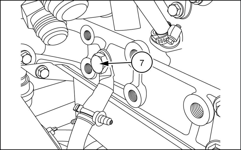
931002029 3 Disconnect air restriction sensor (7) 931002030 4 4771 1677 06/05/2014 10.1 [10.001] / 5
Remove the two retaining bolts (6) from the muf fler

Loosen the hose clamps the intake tube both remove the intake tube (8) , cover turbocharger inlet avoid entry debris.

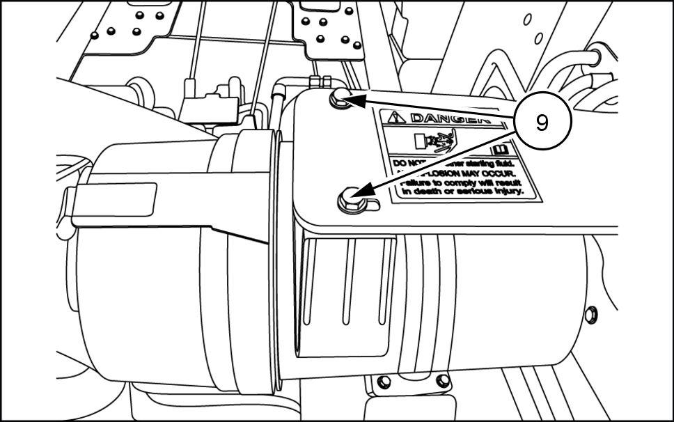
10. Remove air cleaner housing (9) .

1 Loosen hose clamp and remove upper radiator hose (10) from
Engine
Engine -
and crankcase
931002031 5
931002032 6
931002033 7
931002034 8 4771 1677 06/05/2014 10.1 [10.001] / 6
Disconnect the glow plug connection Remove wire clamp (12)
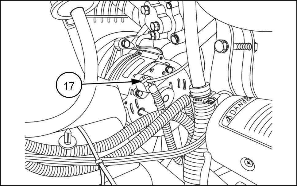
Engine - Engine and crankcase 13. Disconnect the starter connections (13) . 931002035 9 14. Disconnect the alternator connection (14) . 931002036 Disconnect temperature sender wire (15) 931002037 1 1 Disconnect oil pressure sender wire (16) and wire clamp (17) 931002038 4771 1677 06/05/2014 10.1 [10.001] / 7

17. Disconnect throttle cable removing the nut (A) and bolt (B) from the throttle body Remove cable support clamp (C) loosening the two hex head bolts (D)

931002039

18. Disconnect wire harness (18) and clamps (19) from the top the flywheel

931002040

W ARNING

Fire hazard!

When handling diesel observe the ing precautions: not smoke.

Never fill the tank when the engine running.

W ipe spilled fuel immediately

Failure comply could result death serious injury .

W0099A

W ARNING

Escaping fluid!

Hydraulic fluid diesel fuel leaking under pressure can penetrate the skin and cause infection other injury . T o prevent personal injury: Relieve all pressure before necting fluid lines performing work the hydraulic system. Before applying pressure, make sure all connections are tight and all components are good condition. Never use your hand check for suspected leaks under Use a piece cardboard wood for this purpose. injured leaking fluid, see your doctor immediately . Failure comply could result death serious injury .

W0178A

Place a suitable container under lines prevent spillage and remove the fuel supply line (20) .

931002042

Engine - Engine and crankcase
4771 1677 06/05/2014 10.1 [10.001] / 8

20. Remove the fuel return line (21) . 931002041

21. Disconnect the spade connector (E) from the back side the fuel shut f 931002043

Place a suitable container under the remote engine oil filter Label and disconnect oil filter lines (22)

NOTE: Cap the ends avoid entry 931002044

Disconnect the ground from the engine (23) the tery quick 931002045

Engine - Engine and crankcase
4771 1677 06/05/2014 10.1 [10.001] / 9
Engine - Engine and crankcase
24. Remove the twelve mounting bolts (24) securing the hydraulic pump the engine plate
931002046
931002049 4771 1677 06/05/2014 10.1 [10.001] /
25. Remove engine oil pan drain hose clamp (F) .
931002050
Remove the front and rear engine mounts (25) , (26) (not
931002047
Remove the four mounting bolts (27) from the fixed remove

Engine - Engine and crankcase

Place a suitable support beam across the skid steer T a suitable strap around the pump and cure the support beam, shown. 931002051

DANGER

Heavy parts!

Support designated component(s) with adequate lifting

Failure comply will result death serious injury . D0018A

Attach proper lifting straps the eye hooks (28) vided the engine. 931002052

Use a suitable hoist carefully lift the engine slightly rearward separate from the hydraulic Once lift the engine and remove from the rear chassis. 931002053

4771 1677 06/05/2014 10.1 [10.001] / 1 1

Engine - Engine and crankcase

Engine - Install DANGER

Heavy objects!

Lift and handle all heavy components using lifting equipment with adequate capacity . Always support units parts with suitable slings hooks. Make sure the work area clear all bystanders. Failure comply will result death serious injury

Attach proper lifting straps the eye hooks (1) vided the front right and rear left the engine.

Using a suitable hoist carefully lower engine into engine compartment the skid steer .

Slowly orient the hydraulic pump coupler the adapter the engine ensuring the attachment engine plate flywheel

Apply L OCTITE ® 243 the threads the bolts (2) . tach engine hydraulic pump mounting plate using the twelve mounting bolts (2) T ighten the mounting bolts (2) a torque - N·m ( - )

D0076A
931002052 1
931002053 2
3 4771 1677 06/05/2014 10.1 [10.001] /
931002046

Engine - Engine and crankcase

Remove support brace and straps from hydraulic 931002051 4 Apply L OCTITE ® 243 the threads the mounting bolts (3) , (4) (not Install front engine ing bolts (3) and rear mounting bolts (4) (not T ighten the front engine mounting bolts (3) a torque 183 - 224 N·m ( 135 - 165 ) T ighten the rear gine mounting bolt (4) (not shown) a torque 121164 ( - 121 ) . 931002047 5 Install Fixed hood and secure with hardware (5) 931002049 6 Install engine oil pan drain hose into clamp (6) 931002050 7 4771 1677 06/05/2014 10.1 [10.001] /

10.

Connect ground from the quick battery disconnect the engine (7)

remote engine oil filter lines (8) .

- Engine
Engine
and crankcase
931002045 8
931002044 9
Connect
931002041 1 1 4771 1677 06/05/2014 10.1 [10.001] /
1 Connect the spade connector the back the fuel shut f solenoid (9)
931002043
Connect the fuel return line (10)

13. Connect the fuel supply line .

14. Connect the wire harness (12) and clamps (13) the top the flywheel

Connect throttle cable installing the nut (A) and bolt (B) the throttle body Install cable support clamp (C) and tighten the two hex head bolts (D)

Connect oil pressure sender wire (14) and support (15)

Engine - Engine and crankcase
931002042
931002040
931002039
931002038 4771 1677 06/05/2014 10.1 [10.001] /

Thank you very much for your reading. Please Click Here. Then Get COMPLETE MANUAL.NOWAITING

NOTE:

If there is no response to click on the link above, please download the PDF document first and then clickonit.

Engine - Engine and crankcase 17. Connect temperature sensor wire (16) . 931002037 18. Connect alternator connection (17) . 931002036 Connect starter connections (18) 931002035 Connect glow plug connection (19) and wire clamp (20) 931002034 4771 1677 06/05/2014 10.1 [10.001] /
hose 931002033 Install air cleaner housing secure with mounting bolts (22) 931002032 Install air cleaner turbo hose (23) and tighten hose T ighten the clamp a torque 3 - 4 N·m ( - ) 931002031 Connect air restriction sensor (24) 931002030 4771 1677 06/05/2014 10.1 [10.001] /
Engine - Engine and crankcase 21. Install upper radiator hose (21) engine and tighten

Engine - Engine and crankcase

25. Install muf fler inlet pipe mounting flange bocharger and secure with the five mounting bolts (25) T ighten mounting bolts (25) a torqueN·m ( - )

931002028

26. Install the two retaining bolts (26) the muf fler

931002029

Place fan hub and secure with the four ing bolts (A) T ighten the four retaining bolts (A) a torque - ( - )

931002027

Install oil cooler See Oil cooler / Heat exchangerInstall (35.300)

Install radiator See Radiator - Install

Add engine

Fill hydraulic oil reservoir See Oil reservoir - Filling (35.300)

Fill See Radiator - Filling

Install Install rear access door See

4771 1677 06/05/2014 10.1 [10.001] /

Throttle linkage - Adjust

L213 TIER 3 [NEM4591 - ]

W ARNING

A void injury!

Always engage the parking brake and switch off the engine before working the machine. Failure comply could result death serious injury .

Before adjust the please inspect all linkage components for wear and Replace components essary

Start the Press and hold the auxiliary ride button (1) for two Release the then press the auxiliary override button (1) toggle next display Continue press and release the auxiliary override button (1) until RPM

Adjust the clevis (1) the end the foot that within the first five degrees handle the pedal starts move. the pedal does not move with the throttle turn the clevis shorten the

Loosen the jam nut (1) , and turn the stop bolt (2) several turns

NOTE: Make sure the plunger through the L - bracket when the jam nut The plunger must move freely through the L - not pinch the L - bracket between the plunger and the washer

Engine - Throttle linkage
W1046A
931007504 1
931 1 1552 2
931 1 1549 3
4771 1677 06/05/2014 10.2 [10.220] / 3

Place the engine throttle low idle position and record the Stop the For specifications gine RPM, please see Engine - General specification

T urn the plunger thumb screw (1)

Start the engine and check the Repeat steps 4 and 5 until achieved the desired RPM.

Start the engine and move the hand throttle (1) the full idle position and record the Stop the For specifications engine please see Engine - General specification

Adjust the plunger thumb screw necessary

Start the engine and check the Repeat steps 7 and 8 until achieved the desired

T urn the stop bolt (1) out until contacts the T ighten the jam nut (2)

Engine - Throttle linkage
931 1 1551 4
931 1 1550 5
931 1 1549 6 4771 1677 06/05/2014 10.2 [10.220] / 4

Turn static files into dynamic content formats.

Create a flipbook
Issuu converts static files into: digital portfolios, online yearbooks, online catalogs, digital photo albums and more. Sign up and create your flipbook.