
SERVICE MANUAL T4.85 / T4.95 / T4.105 Tractor Part number 47531609 English April 2013 Copyright © 2013 CNH Europe Holding S.A. All Rights Reserved.
SER VICE MANUAL
T4.105, less cab, with mechanical power shuttle transmission [ZxJY5xxxx]
, T4.105, less cab, with mechanical power shuttle transmission [ZxJY5xxxx] , T4.105, with cab, with hi-lo transmission [ZxJY5xxxx] , T4.105, with cab, with mechanical power shuttle transmission [ZxJY5xxxx] , T4.105, with cab, with mechanical power shuttle transmission [ZxJY5xxxx]

, T4.85, less cab, with mechanical power shuttle transmission [ZxJY5xxxx]
, T4.85, less cab, with mechanical power shuttle transmission [ZxJY5xxxx]
47531609 06/05/2013

, T4.85, with cab, with hi-lo transmission [ZxJY5xxxx] , T4.85, with cab, with mechanical power shuttle transmission [ZxJY5xxxx] , T4.85, with cab, with mechanical power shuttle transmission [ZxJY5xxxx] , T4.95, less cab, with mechanical power shuttle transmission [ZxJY5xxxx] , T4.95, less cab, with mechanical power shuttle transmission [ZxJY5xxxx] , T4.95, with cab, with hi-lo transmission [ZxJY5xxxx] , T4.95, with cab, with mechanical power shuttle transmission [ZxJY5xxxx] , T4.95, with cab, with mechanical power shuttle transmission [ZxJY5xxxx]
47531609 06/05/2013
Link Product / Engine
Product
T4.105, with cab, with mechanical power shuttle transmission [ZxJY5xxxx]
Market Product Engine
North America
F5DFL413L*A001
F5DFL413L*A001
T4.105, less cab, with mechanical power shuttle transmission [ZxJY5xxxx]
T4.105, less cab, with mechanical power shuttle transmission [ZxJY5xxxx]
T4.105, with cab, with mechanical power shuttle transmission [ZxJY5xxxx]
T4.105, with cab, with mechanical power shuttle transmission [ZxJY5xxxx]
Europe
F5DFL413L*A001
International Region
F5DFL413L*A001
Europe
International Region
Europe
T4.105, with cab, withtransmission [ZxJY5xxxx]
International Region
F5DFL413L*A001
F5DFL413L*A001 with cab, withtransmission [ZxJY5xxxx]
F5DFL413L*A001
F5DFL413J*A001
T4.85, less cab, with mechanical power shuttle transmission [ZxJY5xxxx]
North America
F5DFL413J*A001
T4.85, with cab, with mechanical power shuttle transmission [ZxJY5xxxx]
North America
T4.85, less cab, with mechanical power shuttle transmission [ZxJY5xxxx]
International Region
F5DFL413J*A001
47531609 06/05/2013
Product
T4.85, less cab, with mechanical power shuttle transmission [ZxJY5xxxx]
T4.85, with cab, with mechanical power shuttle transmission [ZxJY5xxxx]
T4.85, with cab, with mechanical power shuttle transmission [ZxJY5xxxx]
Market Product Engine
F5DFL413J*A001
Europe
F5DFL413J*A001
Europe
International Region
Europe
T4.85, with cab, withtransmission [ZxJY5xxxx]
T4.95, less cab, with mechanical power shuttle transmission [ZxJY5xxxx]
International Region
North America
F5DFL413J*A001
F5DFL413J*A001 with cab, withtransmission [ZxJY5xxxx]
F5DFL413J*A001
F5DFL413K*A001
F5DFL413K*A001
T4.95, with cab, with mechanical power shuttle transmission [ZxJY5xxxx]
North America
T4.95, less cab, with mechanical power shuttle transmission [ZxJY5xxxx]
T4.95, less cab, with mechanical power shuttle transmission [ZxJY5xxxx]
T4.95, with cab, with mechanical power shuttle transmission [ZxJY5xxxx]
International Region
F5DFL413K*A001
Europe
International Region
F5DFL413K*A001
47531609 06/05/2013
F5DFL413K*A001
Product
T4.95, with cab, with mechanical power shuttle transmission [ZxJY5xxxx]
Market Product Engine
F5DFL413K*A001
Europe
T4.95, with cab, withtransmission [ZxJY5xxxx]
Europe
T4.95, with cab, withtransmission [ZxJY5xxxx] International Region
T4.105, less cab, with mechanical power shuttle transmission [ZxJY5xxxx]
North America
F5DFL413K*A001
F5DFL413K*A001
F5DFL413L*A001
47531609 06/05/2013
Contents INTRODUCTION Engine . . . . . . . . . . . . . . . . . . . . . . . . . . . . . . . . . . . . . . . . . . . . . . . . . . . . . . . . . . . . . . . . . . . . . . . . . . . . . . . . . . . . . . . Engine and crankcase Clutch . . . . . . . . . . . . . . . . . . . . . . . . . . . . . . . . . . . . . . . . . . . . . . . . . . . . . . . . . . . . . . . . . . . . . . . . . . . . . . . . . . . . . . . Clutch
10] Clutch and
[18.1 12] Slip
. . . . . . . . . . . . . . . . . . . . . . . . . . . . . . . . . . . . . . . . . . . . . . . . . . . . . 18.3 T ransmission . . . . . . . . . . . . . . . . . . . . . . . . . . . . . . . . . . . . . . . . . . . . . . . . . . . . . . . . . . . . . . . . . . . . . . . . . . . . . . [21.AAA] T ransmission generic sub-group . . . . . . . . . . . . . . . . . . . . . . . . . . . . . . . . . . . . . . . . . . . . . . . . . . 21.1 Mechanical transmission external controls Mechanical transmission internal components [21.1 12] Power shuttle transmission . . . . . . . . . . . . . . . . . . . . . . . . . . . . . . . . . . . . . . . . . . . . . . . . . . . . . . . . . 21.4 10] Master clutch housing [21.134] Power shuttle transmission external controls . . . . . . . . . . . . . . . . . . . . . . . . . . . . . . . . . . . . . . 21.6 Power shuttle transmission internal components Creeper [21.162] Reverser . . . . . . . . . . . . . . . . . . . . . . . . . . . . . . . . . . . . . . . . . . . . . . . . . . . . . . . . . . . . . . . . . . . . . . . . . . . 21.9 unit 18] T ransmission/Rear drive 1 Four-Wheel Drive (4WD) system . . . . . . . . . . . . . . . . . . . . . . . . . . . . . . . . . . . . . . . . . . . . . . . . . . [23.202] Electro-hydraulic control . . . . . . . . . . . . . . . . . . . . . . . . . . . . . . . . . . . . . . . . . . . . . . . . . . . . . . . . . . . 23.1 [23.314] Drive shaft . . . . . . . . . . . . . . . . . . . . . . . . . . . . . . . . . . . . . . . . . . . . . . . . . . . . . . . . . . . . . . . . . . . . . . . . . . 23.2 Front axle system . . . . . . . . . . . . . . . . . . . . . . . . . . . . . . . . . . . . . . . . . . . . . . . . . . . . . . . . . . . . . . . . . . . . . . . Powered front axle Front bevel gear set and dif ferential Final drive steering and shafts 47531609 06/05/2013
mechanical release control
components
clutch flywheel damper
Rear bevel gear set and dif ferential
axle
Planetary
Power T ake-Of f (PT . . . . . . . . . . . . . . . . . . . . . . . . . . . . . . . . . . . . . . . . . . . . . . . . . . . . . . . . . . . . . . . . . Rear mechanical
[31.104] Rear electro-hydraulic control . . . . . . . . . . . . . . . . . . . . . . . . . . . . . . . . . . . . . . . . . . . . . . . . . . . . . . 31.2 14] T rear Power T f (PT 16] rear
(PT Brakes and
Hydraulic
10] Parking brake
[33.220] T railer
. . . . . . . . . . . . . . . . . . . . . . . . . . . . . . . . . . . . . . . . . . . . . . . . . . . . . . 33.3 Front axle brake Hydraulic systems Fixed displacement pump [35.322] Regulated/Low pressure system . . . . . . . . . . . . . . . . . . . . . . . . . . . . . . . . . . . . . . . . . . . . . . . . . . . 35.2 [35.204] Remote control valves . . . . . . . . . . . . . . . . . . . . . . . . . . . . . . . . . . . . . . . . . . . . . . . . . . . . . . . . . . . . . 35.3 Main lift system 14] hitch control valve [35.1 16] Three-point hitch cylinder . . . . . . . . . . . . . . . . . . . . . . . . . . . . . . . . . . . . . . . . . . . . . . . . . . . . . . . . . . 35.6 Front loader arm hydraulic system Front loader bucket hydraulic system Hitches, drawbars, and implement couplings . . . . . . . . . . . . . . . . . . . . . . . . . . . . . . . . . . [37.108] Rear hitch external controls . . . . . . . . . . . . . . . . . . . . . . . . . . . . . . . . . . . . . . . . . . . . 37.1 10] Rear hitch Rear hitch linkage [37.162] Front hitch . . . . . . . . . . . . . . . . . . . . . . . . . . . . . . . . . . . . . . . . . . . . . . . . . . . . . . . . . . . . . . . . . . . . . . . . . . 37.4 Steering . . . . . . . . . . . . . . . . . . . . . . . . . . . . . . . . . . . . . . . . . . . . . . . . . . . . . . . . . . . . . . . . . . . . . . . . . . . . . . . . . . . . . 47531609 06/05/2013
Rear
system
and final drives
control
Power T f
controls
service brakes
parking lock
brake hydraulic control
Hydraulic control components [41.206] Pump . . . . . . . . . . . . . . . . . . . . . . . . . . . . . . . . . . . . . . . . . . . . . . . . . . . . . . . . . . . . . . . . . . . . . . . . . . . . . . . 41.2 [41.216] Cylinders . . . . . . . . . . . . . . . . . . . . . . . . . . . . . . . . . . . . . . . . . . . . . . . . . . . . . . . . . . . . . . . . . . . . . . . . . . . 41.3 Wheels . . . . . . . . . . . . . . . . . . . . . . . . . . . . . . . . . . . . . . . . . . . . . . . . . . . . . . . . . . . . . . . . . . . . . . . . . . . . . . . . . . . . . . [44.51 Front wheels . . . . . . . . . . . . . . . . . . . . . . . . . . . . . . . . . . . . . . . . . . . . . . . . . . . . . . . . . . . . . . . . . . . . . . . . 44.1 Cab climate control . . . . . . . . . . . . . . . . . . . . . . . . . . . . . . . . . . . . . . . . . . . . . . . . . . . . . . . . . . . . . . . . . . . . . Heating V entilation [50.200] Air conditioning . . . . . . . . . . . . . . . . . . . . . . . . . . . . . . . . . . . . . . . . . . . . . . . . . . . . . . . . . . . . . . . . . . . . . 50.3 Electrical systems . . . . . . . . . . . . . . . . . . . . . . . . . . . . . . . . . . . . . . . . . . . . . . . . . . . . . . . . . . . . . . . . . . . . . . . [55.000] Electrical system . . . . . . . . . . . . . . . . . . . . . . . . . . . . . . . . . . . . . . . . . . . . . . . . . . . . . . . . . . . . . . . . . . . 55.1 Harnesses and connectors [55.201] Engine starting system . . . . . . . . . . . . . . . . . . . . . . . . . . . . . . . . . . . . . . . . . . . . . . . . . . . . . . . . . . . . . 55.3 [55.301] Alternator . . . . . . . . . . . . . . . . . . . . . . . . . . . . . . . . . . . . . . . . . . . . . . . . . . . . . . . . . . . . . . . . . . . . . . . . . . . 55.4 Battery [55.640] Electronic modules . . . . . . . . . . . . . . . . . . . . . . . . . . . . . . . . . . . . . . . . . . . . . . . . . . . . . . . . . . . . . . . . . 55.6 [55.DTC] F AUL T CODES . . . . . . . . . . . . . . . . . . . . . . . . . . . . . . . . . . . . . . . . . . . . . . . . . . . . . . . . . . . . . . . . . . . . 55.7 Front loader and bucket . . . . . . . . . . . . . . . . . . . . . . . . . . . . . . . . . . . . . . . . . . . . . . . . . . . . . . . . . . . . . . . Front loader and bucket generic Platform, cab, bodywork, and decals . . . . . . . . . . . . . . . . . . . . . . . . . . . . . . . . . . . . . . . . . . . . . Cab Cab doors and hatches [90.1 10] Operator platform less cab . . . . . . . . . . . . . . . . . . . . . . . . . . . . . . . . . . . . . . . . . . . . . . . . . . . . . . . . . 90.3 Engine hood and panels 16] Fenders and guards 47531609 06/05/2013
INTRODUCTION 47531609 06/05/2013 1
Contents INTRODUCTION Advice . . . . . . . . . . . . . . . . . . . . . . . . . . . . . . . . . . . . . . . . . . . . . . . . . . . . . . . . . . . . . . . . . . . . . . . . . . . . . . . . . . . . . . . . . . . 3 Note the Owner W ARNINGS FOR AIR CONDITIONING SYSTEM REP AIR OPERA TIONS 4 Safety rules SAFETY REGULA TIONS . . . . . . . . . . . . . . . . . . . . . . . . . . . . . . . . . . . . . . . . . . . . . . . . . . . . . . . . . 5 Personal safety CAB AIR CONDITIONING SYSTEM . . . . . . . . . . . . . . . . . . . . . . . . . . . . . . . . . . . . . . . . . . 8 Basic instructions . . . . . . . . . . . . . . . . . . . . . . . . . . . . . . . . . . . . . . . . . . . . . . . . . . . . . . . . . . . . . . . . . . . . . . . . . . . . . . . 9 Special tools NOTES FOR EQUIPMENT . . . . . . . . . . . . . . . . . . . . . . . . . . . . . . . . . . . . . . . . . . . . . . . . . . . . . 1 1 Consumables . . . . . . . . . . . . . . . . . . . . . . . . . . . . . . . . . . . . . . . . . . . . . . . . . . . . . . . . . . . . . . . . . . . . . . . . . . . . . . . . . Part identification . . . . . . . . . . . . . . . . . . . . . . . . . . . . . . . . . . . . . . . . . . . . . . . . . . . . . . . . . . . . . . . . . . . . . . . . . . . . . 47531609 06/05/2013 2
Safety rules SAFETY REGULA TIONS
T O PREVENT ACCIDENTS
Most accidents injuries that occur workshops are the result non - - observance simple and fundamental safety
For this MOST CASES THESE ACCIDENTS CAN A VOIDED: foreseeing possible causes and sequently acting with the necessary caution and Accidents may occur with all types vehicle, regardless how well was designed and built. A careful and judicious service technician the best guarantee against Precise observance the most basic safety rule normally suf ficient avoid many serious
DANGER: Never carry out any lubrication maintenance operations when the engine
GENERAL
• Carefully follow specified repair and maintenance
• not wear jewellery , unbuttoned loose articles clothing such as: torn open jackets shirts with open zips that may remain entangled moving advised wear approved safety non - - slip footwear , safety
• not carry out repair operations with someone sitting the driver ’ s seat, unless the person a trained technician who assisting with the operation
• Operate the vehicle and use the implements exclusively from the driver ’ s seat.
• not carry out operations the vehicle with the engine unless specifically
• Stop the engine and ensure that all pressure relieved from hydraulic circuits before removing
• All repair and maintenance operations must carried out using extreme care and
• Service steps and platforms used a workshop the field should built compliance with the safety rules
• Disconnect the batteries and label all controls indicate that the vehicle being serviced. Block the machine and all equipment which should
• not check fill fuel tanks, accumulator batteries, nor use starting liquid when smoking near naked flames, these fluids are
• Brakes are inoperative manually released for repair maintenance such cases, the machine should kept constantly under control using blocks similar
• The fuel nozzle should always contact with the filling Maintain this position until filling operations are completed order avoid possible sparks caused the accumulation static electricity .
• Only use specified towing points for towing the tractor , connect parts carefully sure that all pins and / locks are secured position before applying traction.
Never remain near the towing cables chains that are operating under load
• T ransport vehicles that cannot driven using a trailer a low - - loading platform trolley ,
• When loading unloading the vehicle from the trailer (or other means select a flat area capable sustaining the trailer truck firmly secure the tractor the truck trailer and lock the wheels the position.
• Electric battery - - chargers and similar equipment must only powered auxiliary power supplies with ficient ground insulation avoid electrical shock
• Always use suitable hoisting lifting devices when raising moving heavy
• T ake extra care bystanders are
• Never pour gasoline diesel oil into wide and low
• Never use diesel oil other inflammable liquids cleaning Use non - flammable non - toxic prietary
• W ear safety goggles with side guards when cleaning parts with compressed air
• Limit the air pressure a maximum bar ( psi ) , according local
47531609 06/05/2013
INTRODUCTION
5
• not run the engine confined spaces without suitable
• not use naked cause sparks the area when fuel filling handling highly inflammable
• Never use naked flames for lighting when working the machine checking for
• All movements must carried out carefully when working under , near the vehicle and wear protective ment: goggles and special footwear
• When carrying out checks with the engine request the assistance operator the driver ’ s The operator must maintain visual contact with the service technician all times.
• operating outside the position the vehicle a flat surface and lock working a lock the vehicle position and move a flat area soon safely possible.
• Damaged bent chains cables are not use them for lifting
Always use suitable protective gloves when handling chains
• Chains should always safely Ensure that fastening device strong enough hold the load persons should stop near the fastening trailing chains
• Maintenance and repair operations must carried out a CLEAN and Y eliminate any water oil spillage immediately
• not create piles oil grease - - soaked rags they represent a serious fire hazard; store them a closed metal container
Before starting the vehicle make sure that the driver ’ s seat locked position and always check that the area free persons
• Empty pockets all objects that may fall unobserved into the vehicle parts when
• the presence protruding metal use protective goggles goggles with side special footwear and
• Handle all parts carefully , not put your hands fingers between moving parts, wear suitable safety clothing -safety gloves and
WELDING OPERA TIONS
• When use protective safety devices: tinted safety special gloves and footwear All persons present the area where welding taking place must wear tinted NEVER LOOK A T THE WELDING ARC YOUR EYES ARE NOT SUIT ABL Y
• Where remove the part tool that requires arc welding from the tractor
• Disconnect both battery Isolate the cable ends avoid contact with each other and the tractor
• Position the welder ground clamp near possible the area where welding taking
• Remove the electronic control units located the tractor welding carried out near these control units.
• Never allow welding cables lay near across any electrical wiring electronic component while welding progress.
• Metal cables tend fray with repeated Always use suitable protective devices when handling
ART
• Never start the engine confined spaces that are not equipped with adequate ventilation for exhaust gas
• Never place the body , hands fingers near fans rotating
ENGINE
• Always loosen the radiator cap slowly before removing allow any remaining pressure the system Coolant should topped only when the engine stopped idle
• Never fill with fuel when the engine especially order prevent the outbreak fire a result fuel spillage
• Never check adjust fan belt tension when the engine running. Never adjust the fuel injection pump when the vehicle
47531609 06/05/2013
INTRODUCTION
6
SER VICE MANUAL
Engine
T4.105, less cab, with mechanical power shuttle transmission [ZxJY5xxxx]
, T4.105, less cab, with mechanical power shuttle transmission [ZxJY5xxxx] , T4.105, with cab, with hi-lo transmission [ZxJY5xxxx] , T4.105, with cab, with mechanical power shuttle transmission [ZxJY5xxxx] , T4.105, with cab, with mechanical power shuttle transmission [ZxJY5xxxx]
, T4.85, less cab, with mechanical power shuttle transmission [ZxJY5xxxx]
, T4.85, less cab, with mechanical power shuttle transmission [ZxJY5xxxx]
47531609 06/05/2013
, T4.85, with cab, with hi-lo transmission [ZxJY5xxxx] , T4.85, with cab, with mechanical power shuttle transmission [ZxJY5xxxx] , T4.85, with cab, with mechanical power shuttle transmission [ZxJY5xxxx] , T4.95, less cab, with mechanical power shuttle transmission [ZxJY5xxxx] , T4.95, less cab, with mechanical power shuttle transmission [ZxJY5xxxx] , T4.95, with cab, with hi-lo transmission [ZxJY5xxxx] , T4.95, with cab, with mechanical power shuttle transmission [ZxJY5xxxx] , T4.95, with cab, with mechanical power shuttle transmission [ZxJY5xxxx]
47531609 06/05/2013
Engine -
less with mechanical power shuttle transmission [ZxJY5xxxx] , less with mechanical power shuttle transmission [ZxJY5xxxx] , with with - transmission [ZxJY5xxxx] , with with mechanical power shuttle transmission [ZxJY5xxxx] , with with mechanical power shuttle transmission [ZxJY5xxxx] , less with mechanical power shuttle transmission [ZxJY5xxxx] , less with mechanical power shuttle transmission [ZxJY5xxxx] , with with - transmission [ZxJY5xxxx] , with with mechanical power shuttle transmission [ZxJY5xxxx] , with cab, with mechanical power shuttle transmission [ZxJY5xxxx] , less cab, with mechanical power shuttle transmission [ZxJY5xxxx] , less with mechanical power shuttle transmission [ZxJY5xxxx] , with with - transmission [ZxJY5xxxx] , with with mechanical power shuttle transmission [ZxJY5xxxx] , with with mechanical power shuttle transmission [ZxJY5xxxx]
Contents
[10.001] Engine and crankcase . . . . . . . . . . . . . . . . . . . . . . . . . . . . . . . . . . . . . . . . . . . . . . . . . . . . . . . . . . . . . . . 10.1
47531609 06/05/2013
EngineEngine and crankcase - 001
T4.105, less cab, with mechanical power shuttle transmission [ZxJY5xxxx]
, T4.105, less cab, with mechanical power shuttle transmission [ZxJY5xxxx] , T4.105, with cab, with hi-lo transmission [ZxJY5xxxx] , T4.105, with cab, with mechanical power shuttle transmission [ZxJY5xxxx] , T4.105, with cab, with mechanical power shuttle transmission [ZxJY5xxxx]
, T4.85, less cab, with mechanical power shuttle transmission [ZxJY5xxxx]
, T4.85, less cab, with mechanical power shuttle transmission [ZxJY5xxxx]
, T4.85, with cab, with hi-lo transmission [ZxJY5xxxx] , T4.85, with cab, with mechanical power shuttle transmission [ZxJY5xxxx] , T4.85, with cab, with mechanical power shuttle transmission [ZxJY5xxxx] , T4.95, less cab, with mechanical power shuttle transmission [ZxJY5xxxx] , T4.95, less cab, with mechanical power shuttle transmission [ZxJY5xxxx] , T4.95, with cab, with hi-lo transmission [ZxJY5xxxx] , T4.95, with cab, with mechanical power shuttle transmission [ZxJY5xxxx] , T4.95, with cab, with mechanical power shuttle transmission [ZxJY5xxxx]
47531609 06/05/2013 10.1 [10.001] / 1
Contents EngineEngine and crankcase - 001 TECHNICAL T A Engine General specification 3 SER VICE Engine Remove 5 Install 47531609 06/05/2013 10.1 [10.001] / 2
Engine - Engine and crankcase
Engine - General specification
GENERAL SPECIFICA TIONS 4 Cylinders technical type: T4.85 T4.95 F5DFL413K*A003 F5DFL413J*A006 F5DFL413L*A002 Engine speed - maximum (no load) - maximum (under load) - minimum 2400 - 2500 RPM 2300 RPM 700 - 800 RPM Cycle 4 - stroke Fuel injection Direct Number cylinders line 4 Bore - All Models Piston diameter Piston stroke ( ) 1 ( 4.3307 ) T otal displacement: - All models 3400 cm³ Compression ratio - All models ± : 1 Maximum Power : T4.85 T4.95 Maximum power speed ( ) ( ) ( 107 ) 2300 RPM Maximum torque T4.85 T4.95 T4.105 Maximum torque speed 351 N·m ( ) 407 N·m ( 300.19 ) 444 ( 327.48 ) 1500 RPM T orque rise T4.85 T4.95 − % % % Power PT O T4.95 T4.105 ( ) 68.6 ( 93.3 ) 73.9 ( 100.4 ) Number main bearings 5 Sump structural, cast iron L forced, with lobe pump Pump drive from crankshaft Oil filtration mesh screen oil intake and filter cartridge delivery line Engine oil pressure switch operating pressures: - contacts closing* with decreasing pressure. - contacts with increasing * with the contacts closed the engine oil pressure warning light 0.2 bar ( 2.90 psi ) bar ( psi ) Cooling coolant circulation Radiator Fill Capacity Fan with viscous fixed the relative pulley with five rows vertical pipes l ( gal ) ø 520 ( 20.4724 ) plastic with blades Coolant pump Centrifugal vane - type Coolant thermometer colored scale divided into three sections T emperature ranges corresponding each section: initial blue section red end section temperature okay temperature excess 47531609 06/05/2013 10.1 [10.001] / 3
GENERAL SPECIFICA TIONS
4 Cylinders
T emperature adjustment - start opening via thermostat valve ( )
T iming
overhead valves operated tappets, rods and rocker arms via the camshaft located the engine block; the camshaft driven the crankshaft using straight - tooth gears Intake:
Clearance between valves and rocker arms with engine The valve clearance hydraulically manual adjustment not necessary
Boost T urbocharged with intercooler
Air cleaning dual cartridge dry air cleaner , with clogged filter indicator with centrifugal pre - filter and automatic dust ejector
Fuel filtration mesh prefilter the supply suction line filter with water - fuel separator , low pressure filter and sensor
Priming pumpInjection pump
T ype
Nozzle type Injection pressure
Filling:
sump - Fuel tank
Manual mounted suction filter
BOSCH
High pressure Common Rail control unit HPCRCP4.1 Electro - Injectors 300 - 1400 bar ( - psi )
l ( - gal )
l ( 30.38 gal ) Anti - pollution system
T ype :
gas recirculation system EGR Particulate filter DPF* Recommended frequency for renewing filter every 3000 Hours
NOTE: * - For filter maintenance please refer to:( Diesel Particulate Filters (DPF) - Dynamic description manual regeneration the diesel particulate filter (DPF) (55.408) )
Engine - Engine and crankcase
°
start:
end:
°
start: before P end: after P .M.I.
° Exhaust:
before P .M.I.
after P .M.S.
°
Engine
-
1
Exhaust
47531609 06/05/2013 10.1 [10.001] / 4
Engine - Engine and crankcase
Engine - Remove
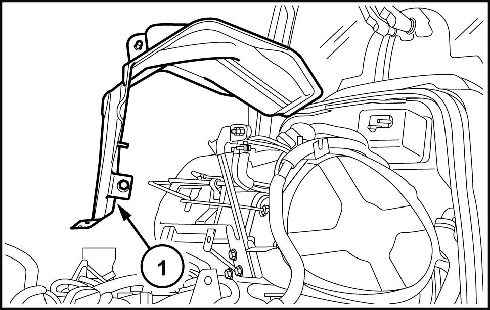
Remove the hood (1) indicated Hood - Remove (90.100)
Remove the split pins, retaining pin and front ballast assembly (1) from the
WLAPL4S10C103A 1
Unscrew the fixing screws (1) and remove the front wheel mudguards (2) (if applicable) this both WLAPL4S10C104A 2
Remove the fixing bolts (1) and detach the engine left - hand side panel (2) Carry out the same tion for the side panel Remove the glove


Recover the refrigerant from the system via the connections (1) and (2) using the specific tool 380000315 . Detach the pipe (1) , clear the section brackets and move onto the condenser ( (1) , 5 detach the pipe (2) , clear the section and take the
WLAPL4S10C105A 3
4 47531609 06/05/2013 10.1 [10.001] / 5
WLAPL4S10C106AA
Subsequently onto the front detach the lower pipe (3) the condenser (1) free from any straps disconnect the sensor (2) and take the


Drain the fuel from the tank removing the bottom drain

Unscrew the fixing bolts (1) and remove the righthand steps (2) .
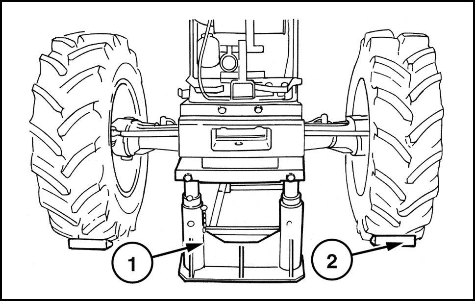
Raise the rear the tractor with a hydraulic put a mechanical stand under the reduction unit with a pneumatic gun remove the left - hand rear wheel retaining and subsequently take f the

Engine - Engine and crankcase
WLAPL4S10C107A 5
6
WLAPL4S10C108A
WLAPL4S10C109A 7
WLAPL4S10C1 10A 8 47531609 06/05/2013 10.1 [10.001] / 6
10. Detach the tank retaining straps (1) , mark and tach the fuel pipes (2) and extract the fuel tank (3) Remove also the bottom tank guard (4)


1 Unscrew the front central and rear retaining bolts the front axle shaft then remove the guard (1)
Remove the circlip (2) and move the front sleeve (1) the direction indicated the arrow until leased from the groove the front
Remove the circlip (2) retaining the coupling sleeve the propeller shaft (1) the move the sleeve the

Engine - Engine and crankcase
WLAPL4S10C1 1 9
WLAPL4S10C1 12AA
WLAPL4S10C1 13AA 1 1
WLAPL4S10C1 14AA 47531609 06/05/2013 10.1 [10.001] / 7
14. T ake out the screws fixing the central support (1) the propeller shaft and remove the shaft together with the remove also the shaft end float adjuster shim the

Loosen the union the cab heater radiator coolant return drain and collect the engine
T ake out the plug (1) and drain the oil from the box - - transmission casing.

Loosen the hose (2) clamp DPF and detach the return pipe (1)


Engine - Engine and crankcase
WLAPL4S10C1 15AA
WLAPL4S10C1 16A
WLAPL4S10C1 17A
47531609 06/05/2013 10.1 [10.001] / 8
MOIL12TR00559AA
18. Loosen the fixing clamps (1) and extract the pipe from the turbine the radiator intercooler (2) Carry out the same operation for the pipe from the radiator intercooler the engine (3)

Loosen the clamp (2) fastening the air intake pipe the then free the air cleaner (4) together with the support bracket (3) from the screws fixing Disconnect the oil vapor pipe (1) the left - hand side the engine the level the fuel pump; remove

Free the air cleaner bracket - casing support (1) from the fixing screws and remove it.
A TTENTION: The filter outlet union DPF (1) (2) its terminal has a decoupler , that responds temperature variations changing length.
A small misalignment the axis the decoupler with respect the axis the turbine outlet (3) would produce adjustment that would longer line with the direction the tractor , but abnormal transversal adjustment that would impair its durability
Engine and crankcase
Engine -
WLAPL4S10C1 19A
WLAPL4S10C120A
WLAPL4S10C121A
47531609 06/05/2013 10.1 [10.001] / 9
21. Disconnect all the filter sensors, loosen the clamp (4) , remove the entire filter together with the pressure sensing lambda probe and heat guards undoing the four screws (5) fixing the bottom
WLAPL4S10C122A
A TTENTION: Only you have work the parts underneath the DPF advisable remove the
The top part (1) and the right - hand part (2) should moved a when removing the fixing screws (3) the right the engine (these screws work a vertical slot that allows the support (2) take various positions Before disassembly , take some references the position the unit the engine, that during reassembly possible restore the exact position which was first

T o remove the rear unscrew the two upper screws fastening the support (4) support (1) , move the left (5) unscrew the two upper screws for the centering bushings and that secure the left bracket the support (1) regards removing the support (1) and (2) there are special instructions follow .
WLAPL4S10C123A
Detach the steering system pipes (1) and (2) the pipe delivering oil the spool valve (3) Remove the fixings the bracket (4) from the engine


WLAPL4S10C124A
WLAPL4S10C125A
- Engine and crankcase
Engine
47531609 06/05/2013 10.1 [10.001] /
Detach the power steering spool valve outlet pipe the gearbox spool valve (2) , the same filter detach the gearbox spool valve supply pipe (1) .
Subsequently remove the filter together with the port (3) WLAPL4S10C126A
Disconnect the intake pipes from the pump (1) the pump the oil filter intake pipe from the mission (2) , the junction under the the height the cab support.
Disconnect the delivery line the lift (3) again the height the pipe (2)
Detach the delivery pipes (5) the lift and the power steering anti - cavitation tank (6) the


Detach the unit together with the filter (4) , tank (6) , support and the parts piping disconnected ously

Detach the high pressure - power steering pump WLAPL4S10C127A
Detach the pipes the cooler (1) , dif ferential lock (3) and, applicable, front braking assembly (4) .
29. Free the pipes previously detached from the brackets and clamps secured the the same thing also for the pipes directed the steering system cylinder (2) WLAPL4S10C128A the right - hand detach the cab heating (1) , the pipe inserted the engine (3) ing from the expansion loosen the clamps the detach the lower (4) and upper rubber sleeves joining radiatorWLAPL4S10C134A
Engine - Engine and crankcase
47531609 06/05/2013 10.1 [10.001] / 1 1
31. the right - hand side, remove the guard (1) the starter motor (2) , disconnect the starting the battery cut - f the cable joining the nator , also disconnect the alternator and the battery positive free all the wirings detached from the various clamps.


Detach the clamp bolt (3) then remove the ground cables the engine and battery remove the other clamp bolts the motor and remove
the cable (1) the FTP cable - engine interface detach all the connections (2) , leave only those the maxi fuse box and the glow plug control then, after cutting the clamps, collect the cable the front near the control unit (5)
the main engine cable (3) disconnect the connecstarting from the one the control unit (4) , from the maxi fuse box and from the various switches and sensors located the engine after freeing from the clamps, move onto the back the height the right - hand
the left - hand side disconnect the connector the power cable the cab (1) , free from the clamps and move onto the maxi fuse
Detach the bracket (2) supporting the cab cab power and cup filter (3) , disconnect the pipe that joins the latter the mechanical priming pump the sediment filter
WLAPL4S10C139A
Hook the rear part the engine onto a hoist using chains ropes for the hoisting (apply two eye one the right and one the the upper part the flange containing the Position a fixed stand (2) under the clutch housing (1) near the engine attachment flanging and apply the
WLAPL4S10C129A
- Engine and crankcase
Engine
WLAPL4S10C135A
WLAPL4S10C137A
47531609 06/05/2013 10.1 [10.001] /
Engine - Engine and crankcase
38. Position the movable tractor stand 380000569 (2) (1) with the bracket and adapter plate under the engine and place a wooden block between the points contact between the stand and W edge the axle prevent


WLAPL4S10C140A
Remove the fixing screws (1) between the engine and the WLAPL4S10C130A
Separate the engine (1) from the transmission with the tool 380000569 (2) .
WLAPL4S10C131AA
Insert the fixed stand (1) under the ballast support and secure the front wheels with wooden blocks (2)
WLAPL4S10C132AA
47531609 06/05/2013 10.1 [10.001] /
Engine - Engine and crankcase

42. Position a fixed stand (3) under the support the groove (1) the front axle drive placing a wooden plug between parts (3) and (1)
Set a stand under the back the engine able release the hoist with the coupling device full safety

Add a rope chain also the front the engine and take the slack with the lifting keeping the engine
Remove the bolts (1) fastening the front axle support (2) the engine. Remove the adjuster spacers for the support - monobloc (4) / sump (3)
Check that there are brackets between the engine and the cooling assembly , detach the engine (2) from the front (3) trying avoid incorrect movements with the hoist order not damage the radiator fins (1) with the engine Rest the engine (2) a

 WLAPL4S10C133A
WLAPL4S10C136A
WLAPL4S10C141A
WLAPL4S10C133A
WLAPL4S10C136A
WLAPL4S10C141A
47531609 06/05/2013 10.1 [10.001] /
WLAPL4S10C138A
Thank you very much for your reading. Please Click Here. Then Get COMPLETE MANUAL.NOWAITING

NOTE:
If there is no response to click on the link above, please download the PDF document first and then clickonit.
46. Remove the viscous coupling (1) , where applicable, together with the fan (2)

Loosen the compressor fixing screws (4) , remove the belt (5) , then remove the compressor
Completely unscrew the belt tensioner (2) , remove the flexible belt (3) , then remove the alternator (1)

Engine - Engine and crankcase
WLAPL4S10C144A
47531609 06/05/2013 10.1 [10.001] /
WLAPL4S10C145A
Engine - Install
- Refit the flexible belt the alternator and take the slack according the procedure AlternatorT ension adjust belt
- Reposition the compressor and the relevant belt following this procedure:
- Reposition the compressor the support and with the relevant pipe support secure with the screws
- T o fit the belt polyv use the tool 38020001 1 .
(1) Compressor clutch actuator drive
(2) polyv belt pulley outer

(3) T ool used drive the tool; this recess houses the bracket (1)
(4) . T ail. Used drive the polyv belt the pulley
(5) Thanks this where the outer edge (2) the tool remains hitched the compressor
Engine - Engine and crankcase
1 47531609 06/05/2013 10.1 [10.001] /
WLAPL4S10C101C
Engine - Engine and crankcase
- T ake out the bolts (1) and the related compressor clutch dust cover
1
Make sure that the polyv (2) belt perfectly housed the fan pulley

- Move the belt (2) near the compressor pulley keeping the tool 38020001 1 under the hook onto the clutch the compressor the innermost part slightly force the
- With your left hand the fan and right hand the move both clockwise take the belt onto the belt the compressor
- Put the dust cup back onto the compressor clutch and tighten the three screws taking care spread a film thread lock the ends they not come
- Where reposition the viscous joint and the cooling
- Apply the required torque settings ( see engine tion)
- Insert the three hooks the chain the eyelets the engine using the lift the assembly f the platform support.
10. - Position the engine the front axle, trying avoid incorrect operations with the hoist not let the engine fan damage the fins the radiator , then join the two assemblies together with the four ing bolts and the necessary adjuster spacers for the monobloc / sump support.
- Reposition the movable tool for dismantling tractors 380000569 under the engine and place a wooden block between the point contact between the tool and

WLAPL4S10C142A 2
WLAPL4S10C143A 3
47531609 06/05/2013 10.1 [10.001] /
12. - With the aid the hoist, place the engine the tool 380000569 and remove the lifting eye bolts viously fitted the rear the
- Remove the fixed stand previously positioned under the support the groove the drive the front axle and the wooden
- Remove the fixed U - - bolt fitted beforehand under the ballast support and the two wooden wedges ing the front
- Remove the old sealing paste from the two surfaces between the engine and clutch
- Apply L OCTITE ® 518 sealing compound the gine and clutch casing mating surfaces.
- Put a wooden block under the right - hand rear make sure that the handbrake fully applied and that all fixed and mobile stands are safely
18. - The installation phase described here requires the presence two three workers use the movable tool for dismantling tractors 380000569 move the engine / front axle assembly close the gearbox.
19. - the phase installing the engine / front axle sembly the necessary push the front taking great care the end phase coupling over both the pipes and the cables / cal connections prevent crushing between the two bodies. During this phase, moreover necessary turn the crankshaft with the aid the radiator ing fan help the coupling between the sleeve and the drive
- Secure both assemblies tightening all the bolts locking the engine the gearbox.
- Disconnect the hoist remove the U - - bolt viously fitted under the clutch casing and recover the movable tool for dismantling tractors 380000569 .
22. - Refit the bracket supporting the cab connectors, cab power and cup filter , connect the pipe that joins the latter the mechanical priming pump the iment filter .
- the left - hand connect the cab power cable connector , take onto the maxi fuse box and lock with
- Return the main engine cable back into connect the connectors the sensors and switches located the the control unit and the maxi fuse fasten the wiring with
- Lay out the FTP interface - engine cable the reconnect the various connections and secure the wiring with
- Fit the starter motor back then connect the two ground wires the engine and battery system.
- Engine and crankcase
Engine
47531609 06/05/2013 10.1 [10.001] /
27. - the right - hand side reconnect the battery tive cable and the wirings the starter motor , battery cut - f switch and alternator Fit the guard back onto the starter motor
- Refit the two delivery and return lines the cab heater and the pipe inserted the lower sleeve coming from the expansion Refit the upper and lower sleeves the radiator engine connection. cure the straps and clamps tightening the
- Reconnect the power steering spool valve oil ter together with the Reconnect the power steering oil drain pipe and the supply pipe the spool valve the
- Refit the two oil delivery and return pipes the cooler and secure them with the relevant
31. - Reassemble the power steering pump. Fit back the transmission oil filter assembly and fix the reconnect the delivery piping the lift and the power steering anti - cavitation assembly the the oil filter inlet from the and the two suction lines from the filter the pump.
32. - Connect the pipes the power steering cylinder and the supply the spool
- was necessary remove the DPF support ceed follows:
1 – Mount the upper support (1) the right one (2) with the three Allen
2 – Mount the left support (5) securing the engine with the three lower
3 – Mount the assembly the supports (1) and (2) the engine with the four screws position (3) , specting the reference marks made when disman-
4 – Secure the support (5) the support (1) with the two upper screws with the two adjustment
5 – Mount the support (4) the engine with the two lower fasten the three left screws the port (5) and with the two upper screws the support (1)

- Fit the DPF filter assembly back returning the entire unit into position and fastening the four fixing screws the assembly the cradle.
Observation:
after refitting the DPF filter you find a slight alignment with the axis the possible make a the two screws fixing the filter the cradle there are two threaded bushings (2) held position a grub screw (1)
Loosen the grub screw with Allen screw the bushing out the amount necessary correct the retighten the grub screw and fix the
35. - Refit the upper bracket supporting the casing and secure with the relevant
Engine - Engine and crankcase
WLAPL4S10C124A 4
WLAPL4S10C146A 5
47531609 06/05/2013 10.1 [10.001] /