

CULTUREservicetechnicians,instrictaccordancewiththeinstructionsgivenandusinganyspecifictoolsnecessary. Anyoneperformingtheoperationsdescribedhereinwithoutstrictlyfollowingtheinstructionsispersonallyresponsible
SafetyrulesSAFETYREGULATIONS
TOPREVENTACCIDENTS
Accidentsmayoccurwithalltypesofvehicle,regardlessofhowwellitwasdesignedandbuilt.
GENERAL
•
• Itisadvisedtowearapprovedsafetyclothing,e.g:non--slipfootwear,gloves,safetygoggles,helmets,etc.
• Donotcarryoutrepairoperationswithsomeonesittinginthedriver’sseat,unlessthepersonisatrainedtechnician
• Operatethevehicleandusetheimplementsexclusivelyfromthedriver’sseat.
•
•
•
• Servicestepsandplatformsusedinaworkshoporinthefieldshouldbebuiltincompliancewiththesafetyrulesin
• Disconnectthebatteriesandlabelallcontrolstoindicatethatthevehicleisbeingserviced.Blockthemachineand
• Donotcheckorfillfueltanks,accumulatorbatteries,norusestartingliquidwhensmokingornearnakedflames,
•
• arecompletedinordertoavoidpossiblesparkscausedbytheaccumulationofstaticelectricity.
• aresecuredinpositionbeforeapplyingtraction.
• Transportvehiclesthatcannotbedrivenusingatraileroralow--loadingplatformtrolley,ifavailable.
• position.
• efficientgroundinsulationtoavoidelectricalshockhazards.
•
•
•
• Neverusegasoline,dieseloilorotherinflammableliquidsascleaningagents.Usenon-flammablenon-toxicpro-
•
• Limittheairpressuretoamaximumof ( 8456801422/03/2013
• • •
• Allmovementsmustbecarriedoutcarefullywhenworkingunder,onornearthevehicleandwearprotectiveequip-
• Whencarryingoutcheckswiththeenginerunning,requesttheassistanceofanoperatorinthedriver’sseat.The operatormustmaintainvisualcontactwiththeservicetechnicianatalltimes.
• lockthevehicleinpositionandmovetoaflatareaassoonasissafelypossible.
•
•
WELDINGOPERATIONS
•
•
Beforestartingthevehicleorimplements,makesurethatthedriver’sseatislockedinpositionandalwayscheck
•
• Removetheelectroniccontrolunitslocatedonthetractorifweldingistobecarriedoutnearthesecontrolunits.
• inprogress.
•
STARTUP
ENGINE
• offuelspillage
• Nevercheckoradjustfanbelttensionwhentheengineisrunning.


GENERALSPECIFICATIONS
4Cylinders
Timing overheadvalvesoperatedbytappets,rodsandrockerarms viathecamshaftlocatedintheengineblock;thecamshaftis
Engine-Remove (1) asindicatedin Hood-Remove (90.100)

WLAPL4S10C101A 1 assembly (1) fromthesupport.
WLAPL4S10C103A 2
andremovethefront wheelmudguards (2) (ifapplicable)Dothisonboth
WLAPL4S10C104A 3
anddetachtheengine


.Carryoutthesameoperationfortheright−handsidepaneltoo.Removethe WLAPL4S10C105A 4
8456801422/03/2013 10.1[10.001]/5


WLAPL4S10C114AA
(1) thepropellershaftandremovetheshafttogetherwith shimontheback.

WLAPL4S10C115AA returnpipe,drainandcollecttheenginecoolant.
WLAPL4S10C116A


(1) box--transmissioncasing. WLAPL4S10C117A

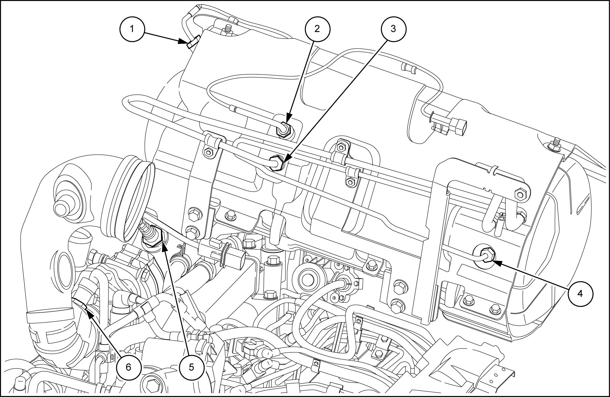
18.Loosenthedevicejoiningtheoutletonthefilter DPF , freetheoutlettubefromanybracketsfasteningitto
WLAPL4S10C118A
(1) andextractthepipe fromtheturbinetotheradiator intercooler(2) outthesameoperationforthepipefromtheradiator intercooler totheengine (3) .
WLAPL4S10C119A
(2) fasteningtheairintakepipe totheturbine,thenfreetheaircleaner (4) together withthesupportbracket (3) Disconnecttheoilvaporpipe (1) oftheengineatthelevelofthefuelpump;removeit


WLAPL4S10C120A
(1) from
WLAPL4S10C121A
ATTENTION: Thefilteroutletunion DPF(1) atitsterminal (2)
(4)
Asmallmisalignmentoftheaxisofthedecouplerwithrespecttotheaxisoftheturbineoutlet (3) wouldproduce
22.Disconnectallthefiltersensors,loosentheclamp

lambda probeand heatguardsbyundoingthefourscrews (5) fixingit
WLAPL4S10C122A
ATTENTION: neaththe DPF
Thetoppart (1) (2)
screws (3) totherightoftheengine(thesescrewsworkon averticalslotthatallowsthesupport (2) totakeonvarious positionsinheight).Beforedisassembly,takesomereferencesonthepositionoftheunitontheengine,sothat duringreassemblyitispossibletorestoreittotheexact


WLAPL4S10C123A
screwsfasteningthesupport (4) support (1) (5) unscrewthetwoupper screwsforthecenteringbushingsandthatsecure theleftbrackettothesupport (1) Asregardsremovingthesupport (1) and (2) there arenospecialinstructionstofollow.
WLAPL4S10C124A (1) and (2) andthe pipedeliveringoiltothespoolvalve (3) Removethefastenersofthebracket (4) gine
WLAPL4S10C125A
thegearboxspoolvalve (2)
thegearboxspoolvalvesupplypipe (1) .

port (3)
WLAPL4S10C126A
mission (2)
(1) onthe
attheheightofthecabsupport.
Disconnectthedeliverylinetothelift (3) againatthe heightofthepipe (2)
Detachthedeliverypipes (5) totheliftandtothe powersteeringanti-cavitationtank (6) (4) (6) ,
WLAPL4S10C127A (1) (3) and,ifapplicable,frontbrakingassembly (4) .
dothesamethingalsoforthepipesdirectedtothe steeringsystemcylinder (2)
WLAPL4S10C128A
(1)
(3)
(4) andupper rubbersleevesjoiningradiator-engine.


WLAPL4S10C134A

(1) onthe startermotor (2) batterycut-offswitch,thecablejoiningittothealterthevariousclamps.

(3) thenremovetheground
WLAPL4S10C135A
(1) ofthe FTP detachalltheconnections (2) then,aftercuttingtheclamps,collectthecableonthe frontnearthecontrolunit (5)


(3) disconnecttheconnec(4) themaxifuseboxandfromthevariousswitchesand fromtheclamps,moveitontothebackattheheight
WLAPL4S10C137A 36.Ontheleft-handsidedisconnecttheconnectorofthe powercableofthecab (1) ,freeitfromtheclamps
(2) (3) thatjoinsthelattertothemechanicalprimingpump
WLAPL4S10C139A
afixedstand (2) undertheclutchhousing (1) near
WLAPL4S10C129A
39.Positionthemovabletoolfordismantlingtractors 380000569(2) withthebracketandadapterplate undertheengineandplaceawoodenblock (1) betweenthepointsofcontactbetweenthetooland


Wedgetheaxletopreventswinging.
WLAPL4S10C140A (1) betweentheengine
WLAPL4S10C130A (1) fromthetransmissionwith thetool 380000569(2) .
WLAPL4S10C131AA (1) undertheballastsupport andsecurethefrontwheelswithwoodenblocks (2)

WLAPL4S10C132AA
8456801422/03/2013
10.1[10.001]/13


followingthisprocedure:

(1)
andtherelatedcompressor
2 polyv(2) beltisperfectlyhoused

(2)
keepingthetool 380200011 ontotheclutchofthecompressorattheinnermost
andtightenthethreescrewstakingcaretospreada filmofthreadlockontheendssotheydonotcome
8.-Applytherequiredtorquesettings(seeenginesection) theplatformsupport. incorrectoperationswiththehoistsoasnottolet ingboltsandthenecessaryadjusterspacersforthe monobloc/sumpsupport.

380000569
undertheengineandplaceawooden blockinbetweenthepointofcontactbetweenthe
8456801422/03/2013 10.1[10.001]/17
Thank you very much for your reading. Please Click Here. Then Get COMPLETE MANUAL.NOWAITING

NOTE:
If there is no response to click on the link above, please download the PDF document first and then clickonit.
16.-Apply L OCTITE
13.-Removethefixedstandpreviouslypositionedunder thesupportofthegrooveofthedriveofthefrontaxle
gineandclutchcasingmatingsurfaces.
presenceoftwoorthreeworkerstousethemovable toolfordismantlingtractors 380000569 tomovethe engine/frontaxleassemblyclosetothegearbox.
calconnectionstopreventcrushingbetweenthetwo bodies.Duringthisphase,itismoreovernecessary ingfantohelpthecouplingbetweenthesleeveand 20.-Securebothassembliesbytighteningallthebolts lockingtheenginetothegearbox.
viouslyfittedundertheclutchcasingandrecoverthe movabletoolfordismantlingtractors 380000569 . imentfilter.
23.-Ontheleft-handside,connectthecabpowercable connector,takeitontothemaxifuseboxandlockit
24.-Returnthemainenginecablebackintoposition, connecttheconnectorstothesensorsandswitches 25.-Layoutthe
26.-Fitthestartermotorbackon,thenconnectthetwo groundwiresontheengineandbatterysystem.
cut-offswitchandalternator.Fittheguardbackonto 28.-Refitthetwodeliveryandreturnlinestothecab heaterandthepipeinsertedonthelowersleeve steeringoildrainpipeandthesupplypipetothe onthetransmissionoilfilterassemblyandfixthe
twosuctionlinesfromthefiltertothepump.
ceedasfollows:
DPF
(1) ontherightone (2)
(5) securingittotheengine (1) and (2) totheenginewiththefourscrewsinposition (3) spectingthereferencemarksmadewhendisman-
(5) tothesupport (1) withthe
(4) totheenginewiththetwo


port (5) andwiththetwoupperscrewstothesupport (1)
DPF
Observation:
Ifafterrefittingthe DPF
entireunitintopositionandfasteningthefourfixing screwsoftheassemblytothecradle.
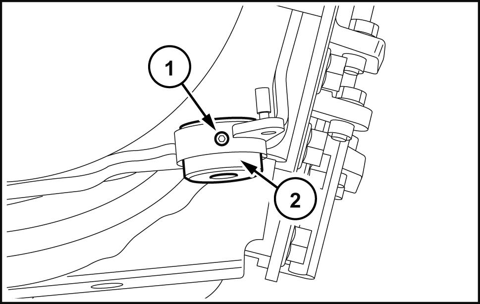
tertothecradletherearetwothreadedbushings (2) heldinpositionbyagrubscrew (1)
thebushinginoroutbytheamountnecessaryto
ontheinletpipeontheradiator.Refitthesleeves intercooler and
38.-Fittheexhaustpipebackonandtightentherelevant retainingclamps. adjusttheshaftendfloat.
tankinpositionandsecureittighteningtherelevant returnthewheelintopositionandmountthefixing
45.-Reconnecttheair-conditioningpipesandthesen-
47.-Rechargetheair-conditioningsystemwithrefrigerantusingthespecificcontrolunit 380000315 .
49.-Refitthefrontwheelmudguards,ifapplicable,and pin. Hood-Install (90.100) 8456801422/03/2013 10.1[10.001]/20
andthatofthealternatorpivot (1)
(2) thenloosen
sioner (4)
WLAPL4S55C301A 1
(1) , (2) and (3) , 1
Thedrivebeltistensionedasfollows:
(5) , 1
Componentsoffigure 2 :
.Alternatorpulley.


308.6mm ( 12.1496in 1.5mm ( 0.0591in fixingholes (10) andtheonewiththeadjustablefixingholes (11)
46mm ( 1.8110in 1mm ( 0.0394in
134mm ( 5.2756in 1mm ( 0.0394in
)Distancebetweenthecentreoftheturbineorthecentreoftheunionof thedecoupler/turbineandtheadjustablefilterfixingbushings (12)
)Distancebetweenthecentreoftheturbineorthecentreoftheunion/ turbineandthebandsupportingsurface (4) withsetfixingholesonthefiltersupport.
5.InitialpartoftheDPFfilter,connectedwiththesleeve. (15) totheturbine. (14)
(6) \endpart (7) (6) \initialpart (5) (3)
keeponetohandandtoreassembleitbeforestartingtodisassemblethefiltersothatthedecouplerundergoes
21.Exhaustgastemperaturesensortotheintakeofthemiddlepartofthefilter.
DieselParticulateFilters(DPF)-Dynamicdescriptionmanual regenerationofthedieselparticulatefilter(DPF)
Adieselparticulatefilter (DPF) isadevicedesignedtoremovepollutingdieselengineparticulatefromexhaustgas;
Theregenerationprocessissignaledtotheoperatoronthecentralmonitorofthedashboardandwithanacoustic signal.Theindicationisnecessaryforthepurposesofsafetytowarntheoperatoraboutthehighexhausttemperature
Theautomaticregenerationshallnotaffectengineperformance.Duringtheprocedure,theoperatorcancontinue
Undercertainoperatingconditionsautomaticregenerationmightnotbecompleted(enginecontinuouslystoppingand dashboardandthesamesymbolappearsevery5minutesonthecentralmonitorwiththeword “ON” combinedwithasinglebeep.Onconcludingtheoperationthesymbolappearswiththeword “OFF” . regeneration.
NOTICE: Ifthefilterisnotregeneratedwhenrequired,whethermanuallyorbyforcing,thefunctionalityofthefilteris
DPFtoberegenerated
Whenthefollowingwarningsappearonthedashboarditisnecessarytoproceedasfollows:
Startofautomaticregenerationor,withthecontrol,start offorcedregeneration


Imagelegend:
WLAPL4S55C111A 1
DPFtoberegenerated Lowseverity
Automaticregenerationinhibited,onlystartofforcedregenerationwithcontrol
DCAPLT5NE058S3A 2

