Catalogue


DATE OF PRINTING: 01.08.2021
The latest Terms and Conditions of Sale and Supply can always be found on our website at: jung.de/terms
JUNG ONLINE CATALOGUE
These and many other devices are available in the JUNG online catalogue. Operating instructions, tender texts, data sheets, product documentation and much more can be found with just one click: jung.de/online-catalogue
Our terms of sale, delivery and payment apply exclusively. The images shown are not binding, in particular with regard to the colour, size and features of the products presented.
SYMBOLS IN THIS CATALOGUE
IP Protection level IP 44 ensured Laser labelling possible with Graphic Tool Print labelling possible with Graphic Tool
JUNG quality is highly regarded all over the world. To meet the needs of its international costumers, the family-run company has established a global network: JUNG has subsidiaries in 20 countries and boasts a total of more than 70 representative agents
on five continents. This way, the company tailors its expertise to the various country-specific requirements and standards. For the users locally, this means a high level of security when dealing with top-grade electrical JUNG products.
 Administration, training centre and production in Schalksmühle
JUNG products are manufactured at the two company sites in Schalksmühle and Lünen. For this JUNG received the certificate “Made in Germany” from TÜV Nord . With deep roots in the region and a constant employer for many decades, today customers throughout the world rely on the continuing high quality. At the same time, JUNG is aware of its high responsibility for sustainable and


energyefficient production. JUNG has proven its specialist know-how in metalworking for decades. The company provides switch designs in genuine metal. Matt finished or lacquered aluminium, stainless steel blasted with glass beads, brushed brass, chromeplated metal or with almost 24 carat gold plating – JUNG produces precision switches down to the last detail every day.

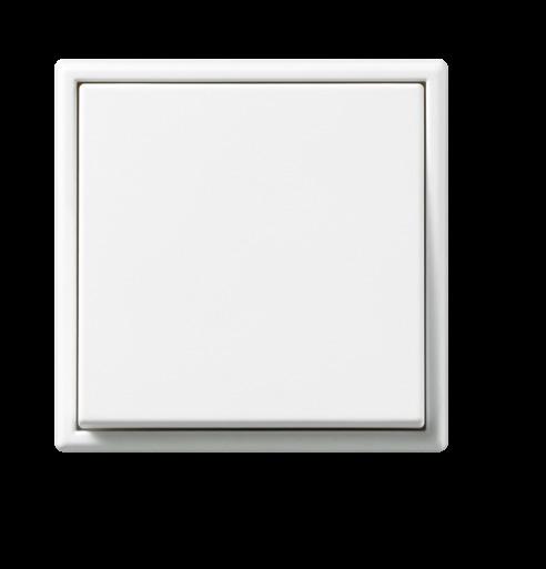


Intensive. Extensive. Elementary. With the matt graphite black and snow white finishes, JUNG creates elegant surfaces that aesthetically enhance the LS, A 550 and A FLOW ranges.
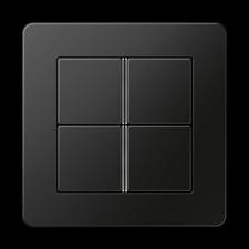
 F 40 SENSOR, 4-GANG
A FLOW in matt graphite black
LS 990 in matt snow white
ROTARY DIMMER
F 50 SENSOR, 4-GANG
A 550 in matt graphite black
LS 990 in matt snow white
SCHUKO® SOCKET

SCHUKO® SOCKET SCHUKO® SOCKET
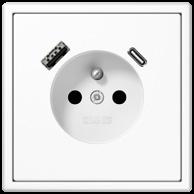
FRENCH / BELGIAN SYSTEM SOCKET HIGHEST SAFETY STANDARDS
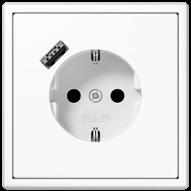
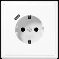
The JUNG SCHUKO® sockets with USB ports, for example, quickly recharge the smartphone, leaving the socket free. The versions with JUNG Quick Charge® have either a USB-A or USB-C
port and are impressive with a charging capacity of up to 18 watts. The sockets with two USB ports (type A and type C) provide particular flexibility.
JUNG SCHUKO ® sockets with USB port are tested and certified by VDE. with USB-C in LS 990 in white with USB-A in LS 990 in white
The digital sample case for travelling: Augmented reality enables digital support for consultancy on location. The AR-Studio app presents the JUNG portfolio with over 2,000 products in the live environment with the customer at home.
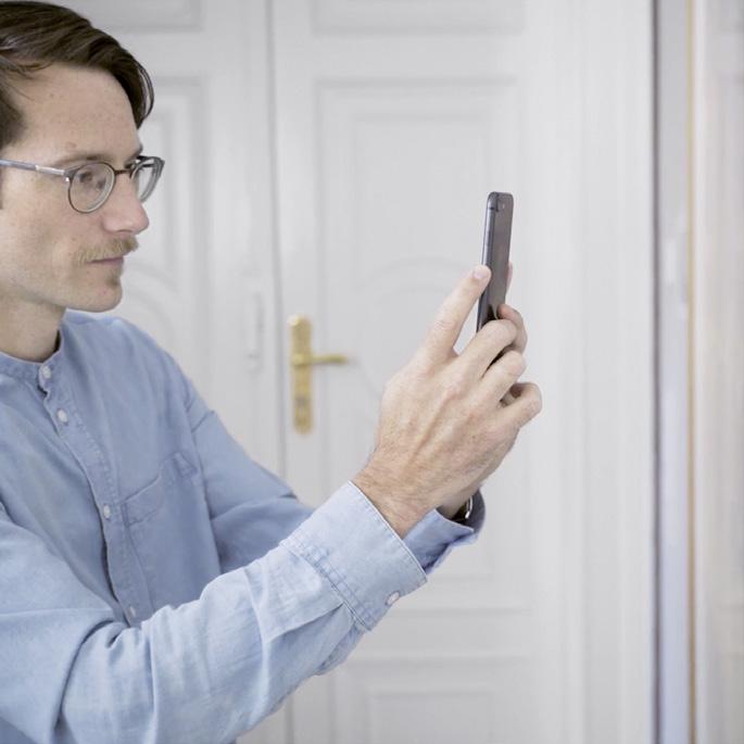
A totally new way to experience JUNG switches and solutions digitally: the JUNG AR-Studio app. Surfaces, materials and colours can be experienced in photographic quality. The app shows all the JUNG ranges, different colours and materials, frame dimensions and much more. All of this free of charge, mobile and independent of network coverage.
Now download the app!
The app for augmented planning offers specialist planners information for carrying out the electrical installation. Precise and reliable. Does the desired switch from the JUNG LS PLUS range fit in? Would a multiple frame work at the door as well? JUNG AR-Studio shows you important information such as frame dimensions at a glance.

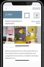
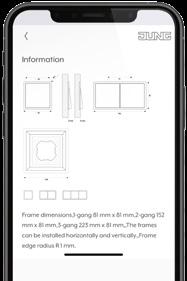
Alongside the true-to-life live views, JUNG AR-Studio provides A range of background information on the JUNG portfolio. The special features of the LS 990, the distinctive design of A CREATION, the large variety of colours in the Les Couleurs® Le Corbusier – the app comprehensively presents the multifaceted world of the JUNG ranges.

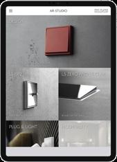
JUNG AR-Studio presents numerous products and shows the large range of functionality of KNX control elements, rotary dimmers and many more: How do other JUNG products look in the customer’s home? Can a KNX push-button be used as well? Does a compact room controller also fit and which operating possibilities does it provide? JUNG AR-Studio knows the JUNG portfolio.

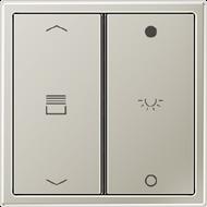
The laser engraving process enables contours of symbols, texts and ornaments due to the precise removal of the surface.
The abrasion-resistant colour printing provides numerous possibilities for individual design.
Integrated inscription fields can be designated via labelling process. This optimises the assignment of functions.
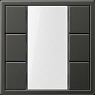


JUNG products gain individuality with the Graphic Tool at www.jung.de/gt. Depending on product, material and personal requirements, laser engraving, colour printing or
labelling are used. With texts, symbols or motifs, both an individual design and an optimisation of the function allocation can be achieved.

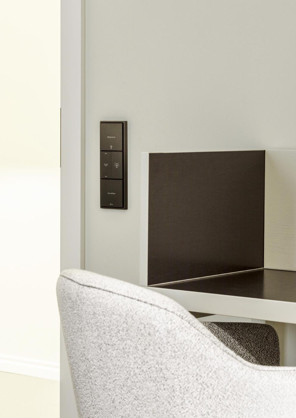 GOURMET HOTEL REFUGIUM STROMBURG, STROMBERG, © PHOTO: HENDRIK SCHIPPER
1-gang switch insert 10 AX / 250 V ~ screwless terminals for wires up to 2.5 mm2 without claws: ref.-no. with additional "E", e.g.: 506 EU
Switch can be illuminated in OFF-position with lamp ref.-no. 90/95 (230 V), 96-.. (low voltage), or LED lamp ref.-no. 90-LED.. (230 V) or 961248 LED.. (low voltage).
1-gang switch insert 20 AX / 250 V ~ screw terminals for wires up to 4 mm2
1-pole, 1-way
U
1-pole, 2-way
1-gang switch insert 16 AX / 400 V ~ screw terminals for wires up to 4 mm2 without claws: ref.-no. with additional "E", e.g.: 503 EU
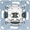


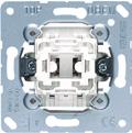
Switch can be illuminated in OFF-position with lamp ref.-no. 98 or 98-220 (230 V).

1-gang switch insert 10 AX / 250 V ~ with indicator light screwless terminals for wires up to 2.5 mm2 Neutral conductor required with glow lamp ref.-no. 90 without claws: ref.-no. with additional "E", e.g.: 506 KOEU
U
U Switch can be illuminated in OFF-position with lamp ref.-no. 98-220 (230 V). intermediate
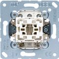

Glow lamp can be replaced with LED lamp ref.-no. 90-LED.. (230 V) or 961248 LED.. (low voltage).
1-gang switch insert 20 AX / 250 V ~ with indicator light screw terminals for wires up to 4 mm2 Neutral conductor required with glow lamp ref.-no. 98-220
1-gang switch insert 16 AX / 400 V ~ with indicator light screw terminals for wires up to 4 mm2 with glow lamp ref.-no. 98
Ref.-no.
1-gang push switch insert 10 A / 250 V ~
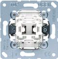
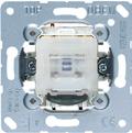
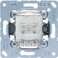
screwless terminals for wires up to 2.5 mm2
Rockers of push switches jump back to original position.
Can be converted into pull cord switch by means of pull cord insert ref.-no. 34 or 34 KO5. without claws: ref.-no. with additional "E", e.g.: 506 ETU
2-pole, 1-way
1-pole, 2-way
illumination not possible in 2-way and intermediate circuits intermediate
502 TU
506 TU
507 TU
Switch can be illuminated in OFF-position with lamp ref.-no. 90/95 (230 V), 96-.. (low voltage), or LED lamp ref.-no. 90-LED.. (230 V) or 961248 LED.. (low voltage).
1-gang push switch insert 10 A / 250 V ~ with indicator light
screwless terminals for wires up to 2.5 mm2
Neutral conductor required with glow lamp ref.-no. 90
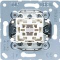
Rockers of push switches jump back to original position.
Can be converted into pull cord switch by means of pull cord insert ref.-no. 34 or 34 KO5. without claws: ref.-no. with additional "E", e.g.: 506 KOETU
2-pole, 1-way
Glow lamp can be replaced with LED lamp ref.-no. 90-LED.. (230 V) or 961248 LED.. (low voltage).
1-gang push-button insert 10 A / 250 V ~
screwless terminals for wires up to 2.5 mm2
Can be converted into pull cord push-button by means of pull cord insert ref.-no. 34 or 34 KO5. without claws: ref.-no. with additional "E", e.g.: 531 EU
1-pole, 1-way (NO contact)
2-way with terminal for N conductor
(NO contact) with separate contacts for indicator light

Illumination possible with lamp ref.-no. 90/95 (230 V), 96-.. (low voltage), or LED lamp ref.-no. 90-LED.. (230 V) or 961248 LED.. (low voltage).
1-gang push-button insert 10 A / 250 V ~
screwless terminals for wires up to 2.5 mm2
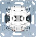
Can be converted into pull cord push-button by means of pull cord insert ref.-no. 34 or 34 KO5. without claws: ref.-no. with additional "E", e.g.: 532 EU
2-pole, 1-way (NO contact)
1-gang push-button insert 10 A / 250 V ~ screw terminals for wires up to 2.5 mm2
Can be converted into pull cord push-button by means of pull cord insert ref.-no. 34 or 34 KO5. without claws: ref.-no. with additional "E", e.g.: 533-2 EU
2-pole, 2-way
1-gang multi switch insert 10 A / 250 V ~ screw terminals for wires up to 2.5 mm2 without claws: ref.-no. with additional "E", e.g.: 531-41 EU


1-pole, 2-way NO contacts, rocker in neutral position
531-41 U
When the upper or lower half of the rocker is actuated, two contacts are closed simultaneously. Especially designed as controller for wirings with relays, e.g. in combination with relay station ref.-no. RS 8 REGHE No electrical/mechanical interlocking. Only recommended for CD and LS ranges (except metal versions).
2-gang switch insert 10 AX / 250 V ~ screwless terminals for wires up to 2.5 mm2 without claws: ref.-no. with additional "E", e.g.: 505 EU
2 x 1-pole, 1-way 505 U
2 x 1-pole, 1-way with 2 glow lamps ref.-no. 94 505 U 5 Switch is illuminated in OFF-position. The lamps can be exchanged without disconnecting mains.
2-gang switch insert 20 AX / 250 V ~ screw terminals for wires up to 4 mm2
2 x 1-pole, 1-way 505-20U
2-gang switch insert 10 AX / 250 V ~ screw terminals for wires up to 2.5 mm2 without claws: ref.-no. with additional "E", e.g.: 509 EU

2 x 1-pole, 2-way
2-gang switch insert 20 AX / 250 V ~ screw terminals for wires up to 4 mm2
2 x 1-pole, 2-way
2-gang switch insert 10 AX / 250 V ~ with indicator light
screwless terminals for wires up to 2.5 mm2 Neutral conductor required
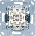

2 x 1-pole, 1-way with 2 glow lamps ref.-no. 94
mechanical interlocking
The lamps can be exchanged without disconnecting mains. Coloured lamps can also be used, e.g.: green ref.-no.: 94 GN or 94-LED GN red ref.-no.: 94 RT or 94-LED RT
2-gang push switch insert 10 A / 250 V ~ screwless terminals for wires up to 2.5 mm2 Rockers of push switches jump back to original position. without claws: ref.-no. with additional "E", e.g.: 505 ETU
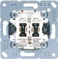
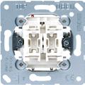

2 x 1-pole, 1-way 505 TU
2 x 1-pole, 2-way
Ref.-no.
2-gang push-button insert 10 A / 250 V ~
screwless terminals for wires up to 2.5 mm2 without claws: ref.-no. with additional "E", e.g.: 535 EU
2 x 1-pole, 1-way (NO contact) 535 U
2 x 1-pole, 1-way (NO contact) with 2 glow lamps ref.-no. 94 535 U 5 Switch is illuminated in OFF-position.

The lamps can be exchanged without disconnecting mains.
2-gang push-button insert 10 A / 250 V ~ screw terminals for wires up to 2.5 mm2 without claws: ref.-no. with additional "E", e.g.: 539 EU
2 x 1-pole, 2-way 539 U
2-gang multi switch insert 10 A / 250 V ~ screw terminals for wires up to 2.5 mm2
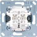


2 x 1-pole, 2-way push-button with 4 NO contacts, rocker in neutral position 532-4 U

Especially designed as controller for wirings with relays, e.g. in combination with relay station ref.-no. RS 8 REGHE. No electrical/mechanical interlocking. Only recommended for CD and LS ranges (except metal versions).
2-gang blind switch insert 10 AX / 250 V ~
screwless terminals for wires up to 2.5 mm2
mechanical interlocking to avoid switching of both rockers at the same time
1-pole (1 motor)
509 VU
2-gang blind push-button insert 10 A / 250 V ~
screwless terminals for wires up to 2.5 mm2
mechanical interlocking to avoid switching of both rockers at the same time
1-pole (1 motor)
539 VU
3-gang switch insert 10 AX / 250 V ~

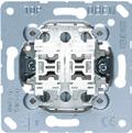

screw terminals
screw fixing only, without claws
Only for A and LS ranges.
When mounting/removing the 3-gang rocker, the middle part has to be clipped on last or removed first.
1-pole, 1-way 5301 EU
1-pole, 2-way 5306 EU
Installation into flush box min. 63 mm (depth)
Rotary switch insert
screw terminals for wires up to 4 mm2
screw fixing only, without claws not suitable for installation in surface caps
Scale disc anthracite
3-level switch with OFF-position 16 AX 250 V ~
2-pole 20 AX 250 V ~
1101-4
1101-20
Installation note: No plaster compensation possible. Insert must be mounted flush with the wall. Supporting frame must be on top of wallpaper.
Rotary switch insert screw terminals for wires up to 6 mm2 screw fixing only, without claws
Scale disc anthracite
including wall box Ø 60 mm, depth 63 mm
Scale disc (Spare part)
ref.-no. 1101-4

1101-20
Timer switch insert 16 AX / 250 V ~ screw terminals for wires up to 4 mm2 screw fixing only, without claws accuracy ± 10 %
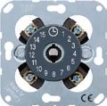
11015
11120-20
Scale disc anthracite
(2 motors) *
* Can also be used as pole changer (see wiring diagram in data sheet).
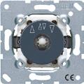
Rotary blind switch insert 10 A / 250 V ~ screw terminals for wires up to 2.5 mm2 Can be converted into rotary push-button by means of locking piece (included). A pre-travel prevents a quick change of direction.
Scale disc (Spare part) for ref.-no. 1234.10, 1234.20


Locking piece (Spare part) for ref.-no.: 1234.10, 1234.20, 834.10 W, 834.20 W
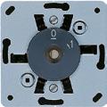
Key switch insert with protection against dismounting screw terminals for wires up to 2.5 mm2 screw fixing only, without claws for locking cylinder with total length of approx. 40 mm, e.g. ref.-no.: 28, 28 G1

10 AX 250 V ~
10 A 250 V ~
Centre plate for key switch can only be dismounted when the lock is in unlocked position.
Blind switch, 1-pole (1 motor)
*
* A pre-travel prevents a quick change of direction.
Blind switch,

1-pole (1 motor) *
* A pre-travel prevents a quick change of direction.
Centre plate for key switch can only be dismounted when the lock is in unlocked position.
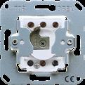
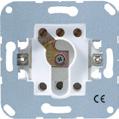

switches (Spare part) 1 piece 28 G1 SL
key
Button lever for the simple and gentle deinstallation of rockers and covers W-KEIL
Pull cord insert for rockers with big lens (.. KO)
red 34
with 50 mm pull cord
The pull cord insert has to be plugged into a 1-gang cover with lens to extend switches or push-buttons with a cord.
Suitable push switches: 506 TU, 507 TU, 502 TU, 506 KOTU, 502 KOTU
Suitable push-buttons: 531 U – 534 U, 631 A – 634 A, 331 A-24
Pull cord insert for rockers with lens (.. KO5)
red 34 KO5
The pull cord insert has to be plugged into a 1-gang cover with lens to extend switches or push-buttons with a cord.
Suitable push switches: 506 TU, 507 TU, 502 TU, 506 KOTU, 502 KOTU
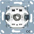
Suitable push-buttons: 531 U – 534 U
Pull cord for pull cord inserts ref.-no: 34 and 34 KO5 length: approx. 2000 mm with spring hook red ZS-34 KO5S


SCHUKO® plug, 16 A / 250 V ~


2-pole with earth contact
Top cable entry ivory

Plug for British Standard sockets
2-pole with earth contact
16 S
screw terminals for wires up to 4 mm2 acc. to BS 1363-1 ivory SA 13
Pilot light insert
screwless terminals for wires up to 2.5 mm2 without claws: ref.-no. with additional "E", e.g.: 938-10 EU max. 5 W, 230 V thread E10 938-10 U thread E14
LED lamp approx. 36 mm long for pilot lights ref.-no.: 938-14 U, 837-14 W, 637-14 W, 637-14 A, 637-14 A WW E14, 230 V ~, 0.4 W
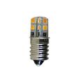

white
green
red
938-14 U
Ref.-no.
Plug-in glow lamp for switches ref.-no.: 506 U, 507 U, 502 U, 806 W, 807 W, 802 W, 806 NAW, 606 W, 607 W, 602 W, 606 NAW for switches with indicator light ref.-no.: 506 KOU, 502 KOU, 806 KOW, 802 KOW, 606 KOW, 602 KOW for push switches ref.-no.: 506 TU, 507 TU, 502 TU for push switches with indicator light ref.-no.: 506 KOTU, 502 KOTU for push-buttons ref.-no.: 531 U, 533 U, 534 U, 831 W, 833 W, 834 W, 631 W, 633 W, 634 W
average life approx. 40 000 h
Plug-in glow lamp for 1-gang switch insert ref.-no.: 503 U, 603 W, 803 W for 1-gang switch insert with indicator light ref.-no.: 501-20 KOU, 502-20 KOU, 506-20 KOU, 503 KOU, 803 KOW
average life approx. 40 000 h
Plug-in glow lamp for 2-gang switch insert ref.-no.: 505 U 5 for 2-gang switch insert with indicator light ref.-no.: 505 KOU 5 for 2-gang push-button insert ref.-no.: 535 U 5
average life approx. 40 000 h
lamp for 2-gang switch insert ref.-no.: 505 U 5 for 2-gang switch insert with indicator light ref.-no.: 505 KOU 5 for 2-gang push-button insert ref.-no.: 535 U 5 average life approx. 100 000 h


Plug-in glow lamp for 2-gang switch ref-no.: 605 W, 805 W, 805 NAW, 835 W, 835 NAW, 605 A, 605 A WW


average life approx. 40 000 h 230 V ~, 0.8 mA white
Plug-in incandescent lamp for switches ref.-no.: 506 U, 507 U, 502 U, 806 W, 807 W, 802 W, 806 NAW, 606 W, 607 W, 602 W, 606 NAW for switches with indicator light ref.-no.: 506 KOU, 502 KOU, 806 KOW, 802 KOW, 606 KOW, 602 KOW for push switches ref.-no.: 506 TU, 507 TU, 502 TU for push switches with indicator light ref.-no.: 506 KOTU, 502 KOTU for push-buttons ref.-no.: 531 U, 533 U, 534 U, 831 W, 833 W, 834 W, 631 W, 633 W, 634 W
life approx. 50 000 h
average life approx. 20 000 h
Ref.-no.
LED lamp for switches ref.-no.: 506 U, 507 U, 502 U, 806 W, 807 W, 802 W, 806 NAW, 606 W, 607 W, 602 W, 606 NAW for switches with indicator light ref.-no.: 506 KOU, 502 KOU, 806 KOW, 802 KOW, 606 KOW, 602 KOW for push switches ref.-no.: 506 TU, 507 TU, 502 TU for push switches with indicator light ref.-no.: 506 KOTU, 502 KOTU for push-buttons ref.-no.: 531 U, 533 U, 534 U, 831 W, 833 W, 834 W, 631 W, 633 W, 634 W for AC and DC, independent of polarity

average life approx. 100 000 h
glow lamp for SCHUKO® socket with pilot light ref.-no. ..520 KO.., 820 KO..
for SCHUKO® socket with pilot light ref.-no. ..520 KO.., 820 KO..
(Spare part) for SCHUKO® socket with pilot light ref.-no. ..1520 ..KO..

Wall box
Depth: 46 mm
Ref.-no.
1056-04
Depth: 63 mm 1556-04
fire resistant up to 650 °C protection level IP 2X device screw distance 60 mm

halogen-free for screw and claw fixing break-out openings for for wires and tubes Ø 20 mm / 25 mm with 2 installation screws 15 mm

Depth: 49 mm
9063-02
Depth: 62 mm 9064-02
halogen-free, colour: white
Depth: 47 mm 9063-78
Depth: 61 mm 9064-78
Wall box for hollow walls, 1-gang cutting hole Ø 68 mm fire resistant up to 850 °C standardised combination distance 71 mm for panel thickness 7 – 40 mm device screw distance 60 mm knockout plugs for for wires and tubes Ø 20/25 mm with 2 installation screws
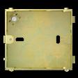

Wall box
depth: 40 mm
depth: 50 mm
BS 6042 M-40
BS 6042 M-50
1-gang, rectangular device screw distance 60.3 mm with earth terminal device screws (M 3 x 30 mm) included Wall boxes can be connected for multiple combinations; center-to-center distance 71 mm. Wall boxes that are installed too deeply or out of square can be readjusted with the plaster compensation frame PCF 6042 to create ideal installation conditions for any flush-mounted inserts.
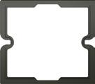
Fire resistant up to 650 °C
The PCF 6042 is a stackable compensation frame made of elastic plastic that allows wall boxes that are installed too deeply or out of square to be readjusted, creating the ideal installation conditions for any flush-mounted inserts.
Flexibly stackable in 1 mm stages
Installation video available: www.jung.de/pcf
Screw set for wall box ref.-no. BS 6042 M-40, BS 6042 M-50
M 3 x 30 mm
M 3 x 50 mm
M 3 x 70 mm
SCREW-30
SCREW-50
SCREW-70
Ref.-no.
50 x 50 system (screw fixing)
For design ranges:
AS / A: with intermediate frame no.: A 590 Z..
CD: with intermediate frame no.: ..590 Z.. or hinged lid no.: CD 590 KL.. or CD 590 BFKL..
SL: with hinged lid no.: SL 590 KL..
LS: with intermediate frame no.: LS 961 Z.. or hinged lid no.: LS 990 KL.., LS 990 BFKL .. or .. 2990 KL..
Centre plate (screw fixing) with inscription field 6 x 37 mm with supporting frame, screw fixing only for universal modular jack socket ref.-no.: UMA-CAT6A for 1 socket
Thermoplastic (breakproof) high-gloss
white 169-1 NWE WW
for 2 sockets
Thermoplastic (breakproof) high-gloss
white 169-2 NWE WW
for modular jack sockets
RADIALL:

modular jack unshielded 6P6C, RJ 12, Cat. 4 (ref.-no. R280MOD804)
modular jack unshielded 8P8C, RJ 45, Cat. 4 (ref.-no. R280MOD805)
modular jack unshielded 8P8C, RJ 45, Cat. 5e (ref.-no. R280MOD807)
Panduit:
keystone jack KJ 88..
keystone jack KJ 588..
Assmann:
module DN-93612 Cat. 6A, shielded, Keystone module DN-93614
SCHRACK
HSPMRJ6G1A, HSEMRJ6GBA, HSEMRJ6GBS, HSEMRJ6GWA, HSEMRJ6GWS, HSEMRJ6UWS
Centre plate (screw fixing) with inscription field 6 x 37 mm with supporting frame, screw fixing only for modular jack sockets
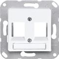
TE Connectivity (Tyco Electronics / AMP NETCONNECT) for cable Ø max. 10 mm:
EMT-jack, Cat. 5e, 180° ref.-no. 0-0188650-5
EMT-jack, Cat. 5e, 90° ref.-no. 0-0188650-6 for cable Ø max. 6.5 mm:
EMT-jack, Cat. 5e, 180° ref.-no. 0-0338038-1
EMT-jack, Cat. 5e, 90° ref.-no. 0-0338038-2
Toolless Jack, Cat. 3 unshielded: ref.-no. 0-1116603-x
Toolless Jack, Cat. 5e unshielded: ref.-no. 0-1116604-x, Toolless Jack, Cat. 5e shielded: ref.-no. 0-1339015-1
Toolless Jack, Cat. 6 unshielded: ref.-no. 0-1116605-x, Toolless Jack, Cat. 6 shielded: ref.-no. 0-1339016-1
MTRJ-LWL jack: ref.-no. 1278414-1 for 1 socket
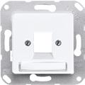
Thermoplastic (breakproof) high-gloss

Centre plate (screw fixing) with inscription field 6 x 37 mm with supporting frame, screw fixing only for modular jack: ref.-no.: 8 FWE for modular jack AMP: 2168-11-1, semi-shielded, cat. 3 for 1 socket
Thermoplastic (breakproof) high-gloss
Centre plate (screw fixing) with inscription field 6 x 37 mm with supporting frame, screw fixing only for modular jack: ref.-no.: 8 FWE for modular jack AMP: 2168-11-1, semi-shielded, cat. 3 for 2 sockets
Thermoplastic (breakproof) high-gloss
Centre plate (screw fixing) with inscription field 6 x 37 mm with supporting frame, screw fixing only for modular jack Radiall: R 280MOD813 for modular jack INFRA +: 7700 U, 7700 D, 7700 E for 2 sockets
Thermoplastic (breakproof) high-gloss
Centre plate for 1-gang modular jack sockets
IAE/UAE sockets ref.-no.: UAE 8 UPO for sockets Cat. 6 ref.-no.: UAE 8 UPOK6 (1 x 8-pol.)
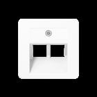


for WLAN access point ref.-no.: WLAN-AC-UAE, WLAN-AC-POE-UAE

Thermoplastic (breakproof) high-gloss
Suitable inserts:
Rutenbeck: UAE 8(4) UPO, UAE 8(8) UPO, UAE-Cat.5e-8 UPO OK, UAE-real.Cat.6-8 UPO OK
Telegärtner: AMJ 45, UMJ 45 and ISDN 1 x RJ 45 (TYP 8)
Centre plate for 2-gang modular jack sockets


IAE/UAE sockets ref.-no.: UAE 2 x 8 UPO, UAE 8-8 UPO for sockets Cat. 6 ref.-no.: UAE 8-8 UPOK6 (2 x 8-pol.)
for media converter 2-gang ref.-no.: MK-POF-2UAE
Thermoplastic (breakproof) high-gloss
Suitable inserts:
METZ CONNECT (BTR): 1307441001-i or 1307441200-i; E-Dat design 8/8(8), Class E
Rutenbeck: UAE 8/8 (8/8) UPO, UAE 2x8 (8) UPO, UAE-Cat.5e-8/8 UPO OK, UAE-real.Cat.6-8/8 UPO OK
Telegärtner: AMJ 45, UMJ 45 and ISDN 2 x RJ 45 (TYP 8/8)
Centre plate for stereo loudspeaker socket ref.-no.: SLA 2 WW, SLA 2 AN for 2-gang supporting frame ref.-no.: UMA-MA2 in connection with universal modular jack socket type A ref.-no.: UMA-CAT6A for USB data interface ref.-no.: 2131 USBS for USB charger ref.-no.: USB 15 CA WW, USB 15 CA SW
Thermoplastic (breakproof) high-gloss
for Rutenbeck: UM-MA 2 Up with UM-real Cat.6a A for Dätwyler: flush-mounted modular jack socket (for 2 x MS-K 1/8 Cat.6a), ref.-no.: 440 012
Centre plate with supporting frame, screw fixing only for loudspeaker socket ref.-no.: PB 4 for chassis connector ref.-no.: CXLR-S, CXLR-D for XLR chassis Neutrik D / DL / DLX Series internal dimensions (W x H): 27.5 x 32.5 mm

Thermoplastic (breakproof) high-gloss
Centre plate for TV-FM sockets ref.-no.: EDU 04 F, GEDU 10, GEDU 15 Duroplastic (scratch-proof) glossy


Socket, 2-pole without earth 16 A / 250 V ~ screw fixing only, without claws Duroplastic (scratch-proof) glossy
SCHUKO® socket 16 A / 250 V ~ screw terminals for wires up to 2.5 mm2 Supporting frame, claws and claw screws are integrated into the earth protection. Thermoplastic (breakproof) high-gloss
ivory
white
brown
green
grey
light grey
orange
black
Thermoplastic (breakproof) lacquered
bronze-beige
platinum-grey
CD 5121 BF
CD 5121 BF WW
CD 5121 BF BR
CD 5121 BF GN
CD 5121 BF GR
CD 5121 BF LG
CD 5121 BF O

CD 5121 BF SW
CD 5121 BF BB
CD 5121 BF PG
Ref.-no.
SCHUKO® socket 16 A / 250 V ~

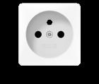
screwless terminals for wires up to 2.5 mm2
Supporting frame, claws and claw screws are integrated into the earth protection.
Thermoplastic (breakproof) high-gloss
ivory CD 5120 BF
white
brown
grey
light grey
black
Thermoplastic (breakproof) lacquered
bronze-beige
platinum-grey
SCHUKO® socket 16 A / 250 V ~ with enhanced contact protection (shutter)
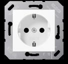

screwless terminals for wires up to 2.5 mm2
Supporting frame, claws and claw screws are integrated into the earth protection.
Thermoplastic (breakproof) high-gloss
CD 5120 BF WW
CD 5120 BF BR
CD 5120 BF GR
CD 5120 BF LG
CD 5120 BF SW
CD 5120 BF BB
CD 5120 BF PG
ivory CD 5120 BFKI
white CD 5120 BFKI WW
Socket insert, French/Belgian system
2-pole + male earth pin, 16 A / 250 V ~
Supporting frame, claws and claw screws are integrated into the earth protection. with claws
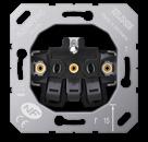

Socket insert, French/Belgian system
2-pole + male earth pin, 16 A / 250 V ~
Supporting frame is integrated into the earth protection. without claws
Centre plate for socket insert French/Belgian system, ref.-no.: 1520 ..F EINS, 1521 ..F EINS with enhanced contact protection (shutter)
Thermoplastic (breakproof) high-gloss
Socket US NEMA system

15 A, 125 V ~, 5-15R, 2-pole + earth with supporting frame, screw fixing only screw terminals for wires up to 4 mm2 acc. to US-NEMA
Thermoplastic (breakproof) high-gloss
Socket US NEMA system
20 A, 125 V ~, 5-20R, 2-pole + earth with supporting frame, screw fixing only screw terminals for wires up to 4 mm2 acc. to US-NEMA
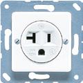
Thermoplastic (breakproof) high-gloss
Potential equalisation socket with supporting frame, screw fixing only with 2 one-pole built-in male sockets according to DIN 42801 for wires up to 6 mm2
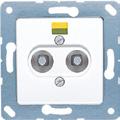
Thermoplastic (breakproof) high-gloss
Right angle plug for potential equalisation socket screw terminal for wires with 4 or 6 mm2

Intermediate frame for AS and A ranges to install devices with 50 x 50 mm cover (DIN 49075)
Thermoplastic (breakproof) high-gloss
lacquered
Intermediate frame CD range to install devices with 50 x 50 mm cover (DIN 49075)
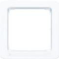


(breakproof) high-gloss
Hinged lid CD range for sockets and devices with 50 x 50 mm cover Thermoplastic (breakproof) high-gloss
versions (anodized aluminium)

Convex hinged lid CD range with inscription field 23 x 59 mm for sockets and devices with 50 x 50 mm cover
Thermoplastic (breakproof) high-gloss
white
Convex hinged lid CD range with inscription field 23 x 59 mm with safety lock for sockets and devices with 50 x 50 mm cover
Thermoplastic (breakproof) high-gloss
white
Key
When ordering, please indicate lock number!

Transparent cover with paper inlay for inscription field 23 x 59 mm (Spare part)

Hinged lid CD range, with spring for sockets and devices with 50 x 50 mm cover
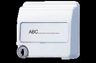
Thermoplastic (breakproof) high-gloss
Hinged lid CD range, with spring with inscription field 9 x 58 mm for sockets and devices with 50 x 50 mm cover Thermoplastic (breakproof) high-gloss
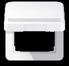

Transparent cover with paper inlay for inscription field 9 x 58 mm
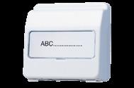
Hinged lid CD range, with spring with safety lock (24 different locks) with inscription field 9 x 39 mm for sockets and devices with 50 x 50 mm cover
Thermoplastic (breakproof) high-gloss
Ref.-no.
ivory L CD 590 BFKLSL
white L CD 590 BFKLSL WW
brown CD 590 BFKLSL BR
grey L CD 590 BFKLSL GR
green CD 590 BFKLSL GN
light grey L CD 590 BFKLSL LG
orange CD 590 BFKLSL O red CD 590 BFKLSL RT
Key
(Spare part) for all hinged lids with safety lock
1 piece 802 SL – 825 SL

When ordering, please indicate lock number!
Transparent cover with paper inlay for inscription field 9 x 39 mm
(Spare part)
paper inlay white

Hinged lid SL range for sockets and devices with 50 x 50 mm cover

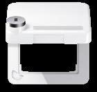
white
gold-bronze
LS 90 NA
SL 590 KL WW
SL 590 KL GB
black SL 590 KL SW
Intermediate frame LS range to install devices with 50 x 50 mm cover (DIN 49075)
Thermoplastic (breakproof) high-gloss
ivory LS 961 Z
white LS 961 Z WW
light grey LS 961 Z LG
black LS 961 Z SW
matt lacquered
matt snow white LS 961 Z WWM
matt graphite black LS 961 Z SWM
Hinged lid LS range, with spring for sockets and devices with 50 x 50 mm cover
Duroplastic (scratch-proof) glossy
ivory
white
P LS 990 KL
P LS 990 KL WW
black LS 990 KL SW
Thermoplastic (breakproof) high-gloss
ivory
white
light grey
L LS 990 BFKL

L LS 990 BFKL WW
black L LS 990 BFKL SW
green
matt lacquered
matt snow white LS 990 BFKL WWM
graphite
metal versions
aluminium
stainless steel
L ES 2990 KL
anthracite (aluminium lacquered) AL 2990 KL AN
dark (aluminium lacquered) AL 2990 KL D
chrome GCR 2990 KL
gold-coloured GO 2990 KL
gold-plated
classic brass
P ME 2990 KL C
antique brass ME 2990 KL AT
Hinged lid LS range, with spring with inscription field 9 x 58 mm for sockets and devices with 50 x 50 mm cover

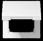
Thermoplastic (breakproof) high-gloss
ivory
white
light grey
black
L LS 990 BFNAKL
L LS 990 BFNAKL WW
L LS 990 BFNAKL LG
L LS 990 BFNAKL SW
green LS 990 BFNAKL GN
orange LS 990 BFNAKL O
red LS 990 BFNAKL RT
Transparent cover with paper inlay for inscription field 9 x 58 mm (Spare part)
paper inlay white CD 90 NA
Hinged lid LS range, with spring with inscription field 12 x 55 mm for sockets and devices with 50 x 50 mm cover
aluminium P
stainless steel
L ES 2990 NAKL
anthracite (aluminium lacquered) AL 2990 NAKL AN
Transparent cover for inscription field 12 x 55 mm (Spare part)
M 20 NA
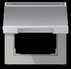
Perfectly connected with the connection systems from JUNG: from mounting adapters for modular jack connectors to data and multimedia connection systems to USB chargers, all requirements are covered here – in both the private and commercial sectors.
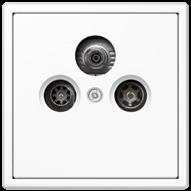
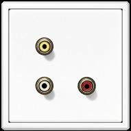
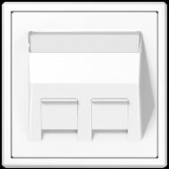
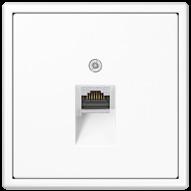
JUNG has developed a terminal especially for smart televisions. The Smart TV Socket combines the fast network connection for streaming over the Internet and classic cable or satellite TV in one unit. Available in the JUNG switch design, it integrates harmoniously into the rest of the electrical installation.
 SMART TV SOCKET
Ref.-no.
UAE

UAE 8-8
Modular jack socket, cat. 3 with screw connection terminals, suitable for ISDN for 6 (RJ 12) and 8 (RJ 45) pole plugs. acc. to DIN EN 60603-7, IEC 603-7
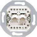
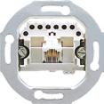
8 screw contacts
8-pole, for 1 terminal
2 x 8-pole, for 2 terminals (parallel)
2 x 8 screw contacts
2 x 8-pole, for 2 terminals (separate)
Category 3 suitable up to 16 MHz
Modular jack socket, cat. 6 / cat. 6A iso, unshielded with LSA connection terminals
2 x 8-pole, for 2 terminals (separate)
RJ 45, category 6A, class EA (10 Gbit/s / 500 MHz), Corresponds to Cat. 6A acc. to ISO/IEC 11801 Amendment 2 and Cat. 6A acc. to TIA/EIA-568-B.2-10 2008 suitable for PoE+ acc. to IEEE 802.3at

UAE 8 UPO
UAE 2X8 UPO
UAE 8-8 UPO
UAE 8-8 UPO K6 US
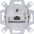
Modular jack socket, cat. 6 / cat. 6A iso screw fixing only, without claws for network applications
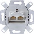
LSA connection terminal, shielded variable running of cable without sharp bending from all directions possible suitable for standard wall boxes
8-pole, for 1 terminal
2 x 8-pole, for 2 terminals (separate)
RJ 45, category 6A, class EA (10 Gbit/s / 500 MHz), Corresponds to Cat. 6A acc. to ISO/IEC 11801 Amendment 2 and Cat. 6A acc. to TIA/EIA-568-B.2-10 2008 suitable for PoE+ acc. to IEEE 802.3at ≥ 1000 insertion/removal cycles, suitable for RJ 11/12
Ref.-no.
UAE 8 UPOK6
UAE 8-8 UPOK6
Centre plates for modular jack sockets: for 1 terminal
AS / A ranges: ref.-no. A 569-1 PLUA ..
CD range: ref.-no. CD 569-1 UA .., CD 569-1 NAUA ..
SL range: ref.-no. SL 569-1 UA ..

LS range: ref.-no. LS 969-1 UA .., LS 969-1 NAUA .., .. 2969-1 UA .., .. 2969-1 NAUA ..
for 2 terminals
AS / A ranges: ref.-no. A 569-2 BFPLUA ..
CD range: ref.-no. CD 569-2 UA .., CD 569-2 NAUA .., CD 590 KL LAN ..
SL range: ref.-no. SL 569-2 UA ..
LS range: ref.-no. LS 969-2 UA .., LS 969-2 NAUA .., .. 2969-2 UA .., .. 2969-2 NAUA .., LS 990 BF KL LAN .., .. 2990 KL LAN ..
Ref.-no.
Universal modular jack socket cat. 6A iso, type A RJ 45, shielded with dust protection cover for covers ref.-no.: 169-1 NWE.., 169-2 NWE.., ..569-1 NWE.., ..569-2 NWE.., ..969-1 NWE.., ..969-2 NWE.. suitable for 10 Gbit Ethernet
UMA-CAT6A
RJ 45, category 6A, class EA (10 Gbit/s / 500 MHz), Corresponds to Cat. 6A acc. to ISO/IEC 11801 Amendment 2 and Cat. 6A acc. to TIA/EIA-568-B.2-10 2008 suitable for PoE+ acc. to IEEE 802.3at ≥ 1000 insertion/removal cycles, suitable for RJ 11/12
• Unmistakable terminals with colour code and numeration (A and B code of the same value)
• For data cables with a diameter of 6 – 10 mm
• For wires of AWG 22 to AWG 24 (rigid/flexible, 7-core cable) Can be combined with 2-gang supporting frame ref.-no.: UMA-MA2 and centre plates .. 569 T .., .. 969 T .. of all design ranges.
2-gang supporting frame for 2 universal modular jack sockets, type A, ref.-no. UMA-CAT6A screw fixing only, without claws Can be combined with centre plates ref.-no. .. 569 T .., .. 969 T .. of all design ranges. suitable for:
Rutenbeck: 13900304
SCHRACK: HSEMRJ6GBA, HSEMRJ6GBS Installation only in cable duct boxes and floor boxes.


Universal modular jack socket cat. 6A iso, type B RJ 45, shielded with dust protection cover for mounting plate ref.-no.: 54-2 BTR suitable for 10 Gbit Ethernet
UMA-MA2
UMB-CAT6A
RJ 45, category 6A, class EA (10 Gbit/s / 500 MHz), Corresponds to Cat. 6A acc. to ISO/IEC 11801 Amendment 2 and Cat. 6A acc. to TIA/EIA-568-B.2-10 2008 suitable for PoE+ acc. to IEEE 802.3at ≥ 1000 insertion/removal cycles, suitable for RJ 11/12

• Unmistakable terminals with colour code and numeration (A and B code of the same value)

• For data cables with a diameter of 6 – 10 mm
• For wires of AWG 22 to AWG 24 (rigid/flexible, 7-core cable)
WLAN access point
• Power supply via 230 V line
• Can be operated as a Wireless Access Point, Client, Repeater or Bridge
• Backside screw terminals (5-pole) for LAN cable
• Frontside LAN connection via RJ45 socket
• Integrated WLAN antenna
• WLAN switchable, timer and timer function
• Wireless range adjustable
• Settings via integrated web server
• Installation in flush box according to EN 60670-1 (recommendation: deep box)
• Not suitable for installation in surface caps
Technical data
Rated voltage: AC 100 ... 240 V ~, 50/60 Hz
Connection mode: screw terminals
Power consumption: max. 3 W
Radio data rate: 150 Mbit/s
Radio standards: IEEE 802.11b/g/n
Frequency range: 2.4 GHz
Security: WEP, WPA, WPA2
Transmitting power: 100 mW (adjustable 2 ... 100 %)
WLAN access point PoE
• Power supply via PoE (class 3)
• Can be operated as a Wireless Access Point, Client, Repeater or Bridge
• Backside screw terminals (9-pole) for LAN cable
• Frontside LAN connection via RJ45 socket
• Additionally, PoE (class 2) is provided at frontside connection
• Integrated WLAN antenna
• WLAN switchable, timer and timer function
• Wireless range adjustable
• Settings via integrated web server
• Installation in flush box according to EN 60670-1 (recommendation: deep box)
• Not suitable for installation in surface caps
Technical data
Rated voltage: PoE 48 V, Class 0, IEEE 802.3at


Connection mode: screw terminals
Power consumption: max. 3 W
Radio data rate: 150 Mbit/s
Radio standards: IEEE 802.11b/g/n

Frequency range: 2.4 GHz
Security: WEP, WPA, WPA2
Transmitting power: 100 mW (adjustable 2 ... 100 %)
Covers for WLAN access points:
AS / A ranges: ref.-no.: A 569-1 ..PLUA ..
CD range: ref.-no.: CD 569-1 UA .., CD 569-1 NAUA ..
SL range: ref.-no.: SL 569-1 UA ..
LS range: ref.-no.: ..969-1 UA .., ..969-1 NAUA ..
50 x 50: ref.-no.: 169-1 UAE WW
Accessories for WLAN access points:
Magnet for reset: ref.-no. PL MAGNET 01
Ref.-no.
Ref.-no.
Media converter 2-gang
2 x RJ45, 1 x POF (Polymer Optical Fiber)
• Installation in flush box according to EN 60670-1 (recommendation: deep box)
• Not suitable for installation in surface caps
Covers:
AS / A ranges: ref.-no.: A 569-2 BFPLUA ..
CD range: ref.-no.: CD 569-2 ..UA ..
SL range: ref.-no.: SL 569-2 UA ..
LS range: ref.-no.: ..969-2 UA .., ..969-2 NAUA ..
50 x 50: ref.-no.: 169-2 UAE WW
Technical data
Rated voltage: AC 100 ... 240 V ~ ± 10 %
Power consumption: typical 0.9 W
Interfaces: 2 x RJ45, 1 x POF (2.2 mm Duplex)

Transfer rate: applications up to 100 Mbit/s

Max. line length: 70 m with POF 2.2 mm
Wavelength: typical 660 nm
Transmission characteristics:
DIN EN 50173-1:2003-06 Category 5
ISO/IEC 11801:2002
DIN EN 50173:2011-09 Category 5
IEC 60603-7-2:2007 unshielded 100 MHz
TIA/IAE-568-B.2-2001 Category 5e
Manufacturers of POF cables are e.g. Rutenbeck and Leoni. Manufacturers of empty conduits with integrated POF cable are e.g. Fränkische Rohrwerke.
Media converter 1-gang
Rail mounting device, 1rail unit
1 x RJ45, 1 x POF (Polymer Optical Fiber)
Technical data
Rated voltage:
AC/DC 8 ... 24 V
Power supply: via external power supply, ref.-no. NT 1220 REG VDC input voltage 100 ... 240 V ~ output voltage DC 12 V / 2 A (not included)

Power consumption: typical 0.9 W
Interfaces: 1 x RJ45, 1 x POF (2.2 mm Duplex)
Transfer rate: applications up to 100 Mbit/s

Max. line length: 70 m with POF 2.2 mm
Wavelength: typical 660 nm
Mounting width: 18 mm (1 rail unit)
Transmission characteristics:
DIN EN 50173-1:2003-06 Category 5
ISO/IEC 11801:2002
DIN EN 50173:2011-09 Category 5
IEC 60603-7-2:2007 unshielded 100 MHz
TIA/IAE-568-B.2-2001 Category 5e
Manufacturers of POF cables are e.g. Rutenbeck and Leoni. Manufacturers of empty conduits with integrated POF cable are e.g. Fränkische Rohrwerke.
MK-POF-UAE-REGRef.-no.
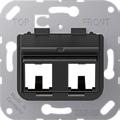
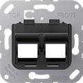
Mounting adapter 30°
suitable for:
JUNG: UMA-CAT6A
3M: VOL-0001, VOL-0002, VOLOCK6ASND8
Assmann: DN 93612, DN 93615
METZ CONNECT (BTR): 130A10-I, 130B23-E, 130B21-E
CobiNet: 6920 0052
Dätwyler: 418 061
eku: t66851000, t66850990
LEONI: 9ZQ01000, 9ZK00026
Nexans:
N420.666 + adapter red N429.625 or adapter blue N429.626
N420.735 + metal adapter N429.620
N420.550 + adapter red N429.625
N420.555 + adapter red N429.625
N420.67A + adapter red N429.625
N420.66A + adapter red N429.625
N420.661 + adapter red N429.625
N420.660 + adapter red N429.625
RADIALL: R280MOD807, R2080MOD810A, R280MOD830, R280MOD803A, R280MOD800, R280MOD834
Reichle & De-Massari: R509509 (incl. adapter keystone)
SETEC: 501415, 501414
SIEMON: MX6-K.., MX5-K.., Z6A-SK(XX), Z5A-SK(XX), Z6A-K01, Z6A-01, MX5-F01, MX6-01, MX6-F01, Z5-S01, MX5-01, Z6-K01, Z6-01, Z6A-S01
Telegärtner: J00029K0036, J00029A2000
SCHRACK: HSPMRJ6G1A, HSEMRJ6GBA, HSEMRJ6GBS, HSEMRJ6GWA, HSEMRJ6GWS, HSEMRJ6UWS
suitable for:
TE Connectivity: 1375187-1, 0-1375189-1, 1375190-1, 0-1375188-1 (replacement for 569013-1), 1375055-1, 1339015-1, 1711592-1

Brand-Rex: AC6JAKU002, AC6JAKU0K2, AC6JAKU000
suitable for:
Commscope (Systimax) MEGALINE: MGS200, MGS500BH-262, MPS100E-003
Reichle & De-Massari:
R808370 (incl. adapter no. 1)
R304373 + adapter R310694
R302372 + adapter R310694
R305111 + adapter R310694
R305112 + adapter R310694
R305113 + adapter R310694
R305114 + adapter R310694
suitable for:
Panduit: CJS688TGY, CJ688TGAW, CMDJAQLCBL, CMDSLCZAW, CJ6X88TGAW, CJ5E88TGAW, CJS5E88TGY

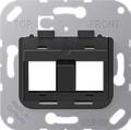
Mounting adapter 30°
suitable for:
LexCom: 306520007 + mounting frame creme 306580030
suitable for:
Brand-Rex: C6CJAKU0K2
Panduit: NK688MBL
TE Connectivity: 1711342-1, 1116604-x, 1116603-x

Centre plate with inscription field 9 x 51 mm for mounting adapter 30° ref.-no.: 3069..
for AS and A ranges
Thermoplastic (breakproof) high-gloss
ivory
white
black
Thermoplastic (breakproof) lacquered
aluminium
matt lacquered
matt anthracite
for LS range
Thermoplastic (breakproof) high-gloss
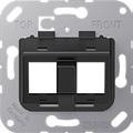
ivory
white
light grey
black
metal colours (thermoplastic lacquered)
aluminium (lacquered)

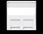
stainless steel (lacquered)
anthracite (lacquered)
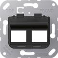
classic brass (lacquered)
antique brass (lacquered)
A 569-30 BF PL
A 569-30 BF PL WW
A 569-30 BF PL SW
A 569-30 BF PL AL
A 569-30 BF PL ANM
LS 569-30 BF PL
LS 569-30 BF PL WW
LS 569-30 BF PL LG
LS 569-30 BF PL SW
AL 569-30 BF PL-L
ES 569-30 BF PL-L
AL 569-30 BF PL AN L
ME 569-30 BF PL C-L
ME 569-30 BF PL AT L
TV-FM socket outlet insert Screwless terminals for cable TV and SAT distribution
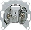
Frequency range 5 ... 2400 MHz without gaps on both outputs. Housing: torsion-resistant, passivated diecast zinc
Terminated outlet
EDU 04 F
Terminated outlets are used for individual and community installation (BK, CATV, MATV) connected to decoupling stub lines.
Technical data
IN – TV (IEC male)
Frequency range: 5 ... 2150 (2400) MHz
Attenuation: 4.0 dB
IN – RF (IEC female)
Frequency range: 5 ... 2150 (2400) MHz
Attenuation: 4.0 dB
Isolation
TV – RF: VHF, UHF / SAT: 20/20 dB DC through TV – IN (IEC male): 13/18 V, 22 kHz max. +24 V/0.5 A
Covers:
AS / A ranges: ref.-no.: A 561 PLTV ..
CD range: ref.-no.: CD 561 SAT ..
SL range: ref.-no.: SL 561 TV ..

LS range: ref.-no.: ..990 TV ..
50 x 50: ref.-no.: 161 TV
Ref.-no.
TV-FM socket outlet insert

Screwless terminals for cable TV and SAT distribution
Frequency range 5 ... 2400 MHz without gaps on both outputs.
Housing: torsion-resistant, passivated diecast zinc
Loop through outlet
GEDU 10
Loop through outlets can also be used in tree networks. The last loop through socket installed in a trunk or stub line must be terminated by terminating resistor R 75.
Technical data
IN – OUT (throughpass)
Frequency range: 5 ... 2150 (2400) MHz
Attenuation: 2.5 dB
IN – TV (IEC male)
Frequency range: 5 ... 2150 (2400) MHz
Attenuation: 10.0 dB
IN – RF (IEC female)
Frequency range: 5 ... 2150 (2400) MHz
Attenuation: 10.0 dB
Isolation
OUT – TV / RF: VHF, UHF / SAT: 35/20 dB
TV – RF: VHF, UHF / SAT: 38/30 dB
DC through: no
Covers:
AS / A ranges: ref.-no.: A 561 PLTV ..
CD range: ref.-no.: CD 561 SAT ..
SL range: ref.-no.: SL 561 TV ..

LS range: ref.-no.: ..990 TV ..
50 x 50: ref.-no.: 161 TV
Ref.-no.
TV-FM socket outlet insert Screwless terminals for cable TV and SAT distribution
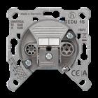
Frequency range 5 ... 2400 MHz without gaps on both outputs. Housing: torsion-resistant, passivated diecast zinc
Loop through outlet
GEDU 15
Loop through outlets can also be used in tree networks. The last loop through socket installed in a trunk or stub line must be terminated by terminating resistor R 75. Note on the use of loop through outlets GEDU 10 and GEDU 15: In a main line with e.g. 7 subscribers the first 4 TV sockets will be GEDU 15 and the remaining ones will be GEDU 10. In this way all sockets will have approximately the same signal strength.
Technical data
IN – OUT (throughpass)
Frequency range: 5 ... 2150 (2400) MHz
Attenuation: 1.0 dB
IN – TV (IEC male)
Frequency range: 5 ... 2150 (2400) MHz
Attenuation: 15.0 dB
IN – RF (IEC female)
Frequency range: 5 ... 2150 (2400) MHz
Attenuation: 15.0 dB
Isolation
OUT – TV / RF: VHF, UHF / SAT: 38/30 dB
TV – RF: VHF, UHF / SAT: 24/24 dB
DC through: no
Covers:
AS / A ranges: ref.-no.: A 561 PLTV ..
CD range: ref.-no.: CD 561 SAT ..
SL range: ref.-no.: SL 561 TV ..

LS range: ref.-no.: ..990 TV ..
50 x 50: ref.-no.: 161 TV
Ref.-no.
SAT-TV-FM socket outlet insert
Screwless terminals
3-gang all-round antenna socket with interconnected frequency bands, thus flexible and future proof. Suitable for SAT IF and CATV domestic distribution installations.
Seamless CATV and SAT ranges and low distribution attenuation thanks to combined filter-tap structure. Housing: torsion-resistant, passivated diecast zinc
Terminated outlet EDA 302 F

Terminated outlets are used for individual and community installation (BK, CATV, MATV) connected to decoupling stub lines.
Technical data
IN – TV (IEC male)
Frequency range: 5 ... 862 MHz
Attenuation: 2.5 dB
IN – RF (IEC female)
Frequency range: 5 ... 118 MHz
Attenuation: 6.5 dB
IN – SAT (F female)
Frequency range: 950 ... 2150 (2400) MHz
Attenuation: 2.2 dB
Isolation
TV – SAT: VHF, UHF / SAT: 20/20 dB
RF – SAT: VHF / SAT: 35/30 dB
TV – RF: VHF, UHF: 20 dB
DC through SAT-IN (F female): 13/18 V, 22 kHz max. +24 V/0.5 A
Covers:
AS / A ranges: ref.-no.: A 561 PLSAT ..
CD range: ref.-no.: CD 561 SAT ..
SL range: ref.-no.: SL 561 SAT ..
LS range: ref.-no.: ..990 SAT ..

Ref.-no.
SAT-TV-FM socket outlet insert Screwless terminals
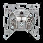
3-gang all-round antenna socket with interconnected frequency bands, thus flexible and future proof. Suitable for SAT IF and CATV domestic distribution installations. Seamless CATV and SAT ranges and low distribution attenuation thanks to combined filter-tap structure. Housing: torsion-resistant, passivated diecast zinc
Loop through outlet GDA 313 F
Loop through outlets can also be used in tree networks. The last loop through socket installed in a trunk or stub line must be terminated by terminating resistor R 75.
Technical data IN – OUT (throughpass)
Frequency range: 5 ... 2150 (2400) MHz
Attenuation: 1.0 ... 2.0 (2.8) dB
IN – TV (IEC male)
Frequency range: 5 ... 862 MHz
Attenuation: 13.0 dB
IN – RF (IEC female)
Frequency range: 5 ... 118 MHz
Attenuation: 17.0 dB
IN – SAT (F female)
Frequency range: 950 ... 2150 (2400) MHz
Attenuation: 12.0 (13.5) dB
Isolation
OUT – TV / RF: VHF, UHF: 28 dB
OUT – SAT: SAT: 18 dB
TV – SAT: VHF, UHF / SAT: 20/20 dB
RF – SAT: VHF / SAT: 35/30 dB
TV – RF: VHF, UHF: 20 dB
DC through SAT-IN (F female): 13/18 V, 22 kHz max. +24 V/0.5 A
Covers:
AS / A ranges: ref.-no.: A 561 PLSAT ..
CD range: ref.-no.: CD 561 SAT ..
SL range: ref.-no.: SL 561 SAT ..

LS range: ref.-no.: ..990 SAT ..
Terminating resistor 75 Ω to terminate the last loop through socket installed in a line for TV-FM socket outlet inserts ref.-no.: GEDU 10, GEDU 15, GDA 313 F R 75
Ref.-no.
Smart TV socket with supporting frame, screw fixing only Cover with snap-on fixing and shutter with spring including universal modular jack socket ref.-no.: UMA-CAT6A and IEC plug module for antenna cables
Technical data
Specification IEC plug module
External connection: coaxial plug IEC 60169-2
Internal connection: F socket IEC 60169-24
Impedance: 75 Ohm
Frequency range: 5 ... 2,400 MHz
Attenuation: 0.0 dB
Installation depth not considering cables
Universal modular jack socket: 40 mm
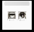
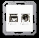
IEC plug module: 30 mm
Use right angle plug.
Consider bending radius. Ensure sufficient installation space.

for AS and A ranges
Thermoplastic (breakproof) high-gloss
white
for LS range with inscription field 9 x 58 mm
Thermoplastic (breakproof) high-gloss white MMD
Ref.-no.
Chassis connector
XLR compatible, with universal housing for male and female version

Chassis (male)
Chassis (female)
Covers:
AS / A ranges: ref.-no.: A 568-1 BF ..

CD range: ref.-no.: 568-1
50 x 50: ref.-no.: 168-1 WW
Gold-plated loudspeaker terminal for professional connection of high quality loudspeaker systems
CXLR-S
CXLR-D
Cable sockets (6 mm and 8 mm fork) or crimped cables (6 mm2) are connected with a patented clamping nut system. The pole terminal body is manufactured in one piece to obtain the least resistance. red identification
LPK 63 RT black identification
Technical data
LPK 63 SW
Internal connection: soldering or crimped connection (crimped ferrule, screw contact) Transition resistance: ≤ 0.1 mΩ clamp connection ≤ 0.15 mΩ banana plug 4 mm
Material: 24 carat gold-plated copper
High quality RCA (phono) socket pair
red/white identification
made of 24 carat gold plated copper, double prismatic contact With special pressure spring mechanic, dielectric made of Teflon Inside connection: soldering


CIB 63
Mounting plate for installation of loudspeaker terminals (ref.-no. LPK 63 RT, LPK 63 SW) or RCA (phono) sockets (ref.-no. CIB 63) in cover for 2 loudspeaker sockets (ref.-no. .. 562 .., .. 962 ..)
63 WBT
Stereo loudspeaker socket
25 V ~, 60 V DC for wires up to 10 mm2 with 4 front side plug terminals in red/black also suitable for SELV
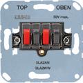
white
SLA 2 WW anthracite
Covers:
AS / A ranges: ref.-no. A 569 PLT ..
CD range: ref.-no. CD 569 T .. (not metal versions)
LS range: ref.-no. .. 969 T .., .. 2969 T ..
SLA 2 AN
Cinch Audio (RCA) / Stereo Jack (TRS 3.5 mm) with supporting frame, screw fixing only
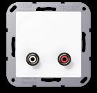
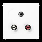
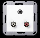
for AS and A ranges
Thermoplastic (breakproof) high-gloss
ivory
black
Thermoplastic (breakproof) lacquered
aluminium
matt
matt
for CD range
Thermoplastic (breakproof) high-gloss white
for LS range
Thermoplastic (breakproof) high-gloss
Cinch Audio (RCA) with supporting frame, screw fixing only
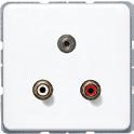
for AS and A ranges
Thermoplastic (breakproof) high-gloss
Thermoplastic

Cinch Audio (RCA) with supporting frame, screw fixing only
for CD range
Thermoplastic (breakproof) high-gloss
for LS range
Thermoplastic (breakproof) high-gloss
Cinch Audio (RCA) / Composite Video with supporting frame, screw fixing only
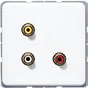
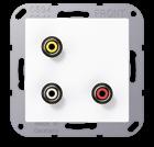
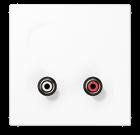
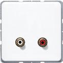
for AS and A ranges
Thermoplastic (breakproof) high-gloss
(breakproof) lacquered
for CD range
Thermoplastic (breakproof) high-gloss

Cinch Audio (RCA) / Composite Video with supporting frame, screw fixing only
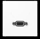

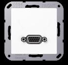

for LS range
Thermoplastic (breakproof) high-gloss
with supporting frame, screw fixing only
for AS and A ranges
Thermoplastic (breakproof) high-gloss
for CD range
Thermoplastic (breakproof) high-gloss
for LS range
Thermoplastic (breakproof) high-gloss

HDMI with supporting frame, screw fixing only Consider bending radius and various plug types. Ensure sufficient installation space.
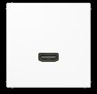
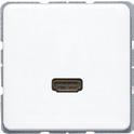
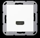
for AS and A ranges
Thermoplastic (breakproof) high-gloss
(breakproof) lacquered
for CD range
Thermoplastic (breakproof) high-gloss
for LS range
Thermoplastic (breakproof) high-gloss
USB 2.0 with supporting frame, screw fixing only Consider bending radius and various plug types. Ensure sufficient installation space.
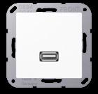
for AS and A ranges
Thermoplastic (breakproof) high-gloss
(breakproof) lacquered

USB 2.0
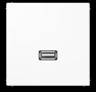
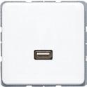
with supporting frame, screw fixing only Consider bending radius and various plug types. Ensure sufficient installation space.
for CD range
Thermoplastic (breakproof) high-gloss
for LS range
Thermoplastic (breakproof) high-gloss
Cinch Audio (RCA) / Stereo Jack (TRS 3.5 mm) / VGA with supporting frame, screw fixing only

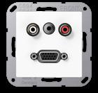
for AS and A ranges
Thermoplastic (breakproof) high-gloss
for CD range
Thermoplastic (breakproof) high-gloss

Cinch Audio (RCA) / Stereo Jack (TRS 3.5 mm) / VGA with supporting frame, screw fixing only
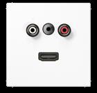

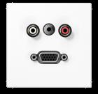
for LS range
Thermoplastic (breakproof) high-gloss
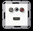
Cinch Audio (RCA) / Stereo Jack (TRS 3.5 mm) / HDMI with supporting frame, screw fixing only Consider bending radius and various plug types. Ensure sufficient installation space.
for AS and A ranges
Thermoplastic (breakproof) high-gloss
(breakproof) lacquered
for CD range
Thermoplastic (breakproof) high-gloss
for LS range
Thermoplastic (breakproof) high-gloss

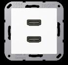
2 x HDMI
with supporting frame, screw fixing only
Consider bending radius and various plug types. Ensure sufficient installation space.
for AS and A ranges
Thermoplastic (breakproof) high-gloss
Thermoplastic (breakproof) lacquered
for CD range
Thermoplastic (breakproof) high-gloss
for LS range
Thermoplastic (breakproof) high-gloss
2 x USB 2.0

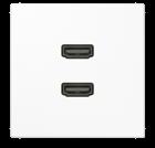
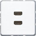
with supporting frame, screw fixing only
Consider bending radius and various plug types. Ensure sufficient installation space.

for AS and A ranges
Thermoplastic (breakproof) high-gloss
Thermoplastic (breakproof) lacquered
2 x USB 2.0 with supporting frame, screw fixing only Consider bending radius and various plug types. Ensure sufficient installation space.

for CD range
Thermoplastic (breakproof) high-gloss
for LS range
Thermoplastic (breakproof) high-gloss
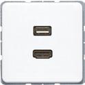
HDMI / USB 2.0 with supporting frame, screw fixing only Consider bending radius and various plug types. Ensure sufficient installation space.
for AS and A ranges
Thermoplastic (breakproof) high-gloss
(breakproof) lacquered
for CD range
Thermoplastic (breakproof) high-gloss

Ref.-no.
Multimedia terminals

with supporting frame, screw fixing only
Consider bending radius and various plug types. Ensure sufficient installation space.

Thermoplastic (breakproof) high-gloss
LS
LS
graphite black MA
HDMI / VGA
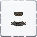
with supporting frame, screw fixing only
for AS and A ranges
1163
1163
ivory MA A 1173 white MA A 1173 WW black MA A 1173 SW
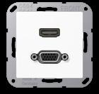
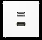
aluminium MA A 1173 AL matt lacquered matt snow white MA A 1173 WWM matt graphite black MA A 1173 SWM matt anthracite MA A 1173 ANM
for CD range
white MA CD 1173 WW
for LS range
1173 white
MA LS
1173 stainless steel
DVI

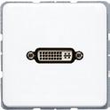
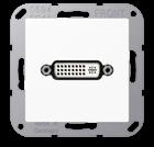

with supporting frame, screw fixing only Consider bending radius and various plug types. Ensure sufficient installation space.
for AS and A ranges
Thermoplastic (breakproof) high-gloss
(breakproof) lacquered
for CD range
Thermoplastic (breakproof) high-gloss
for LS range
Thermoplastic (breakproof) high-gloss
Ref.-no.
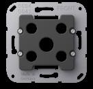
Adapter 1 (Spare part)
for multimedia terminals ref.-no. MA .. 1011 ..
MA 1000 AD 1
Adapter 2 (Spare part)
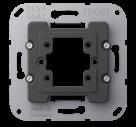
for multimedia terminals ref.-no. MA .. 1072 .., MA .. 1082 .., MA .. 1092 ..

MA 1000 AD 2
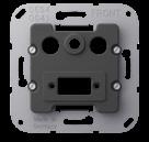
Adapter 3 (Spare part)
for multimedia terminals ref.-no. MA .. 1102 .., MA .. 1112 .., MA .. 1122 .., MA .. 1133 .., MA .. 1143 .., MA .. 1153 .., MA .. 1163 .., MA .. 1173 .., MA .. 1183 .., MA .. 1193 ..
MA 1000 AD 3
Adapter 4 (Spare part)
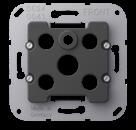
for multimedia terminals ref.-no. MA .. 1021 .., MA .. 1031 .., MA .. 1051 ..
MA 1000 AD 4
SCHUKO® SOCKET
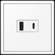
FRENCH / BELGIAN SYSTEM SOCKET
USB CHARGER
with
HIGHEST SAFETY STANDARDS
JUNG SCHUKO ® sockets with USB port are tested and certified by VDE. with USB-A+C in LS 990 in white
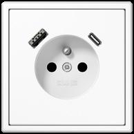
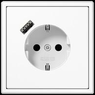
JUNG SCHUKO ® sockets with USB ports quickly recharge smartphones or tablets, leaving the socket free. The versions with JUNG Quick Charge® have a USB-A or USB-C port and impress with a charging capacity of up to 18 watts. The sockets with two USB ports (type A and type C) provide
particular flexibility. Another option for quickly charging mobile devices are the USB chargers with USB type A and C ports and an electrical output of 15 watts. Due to their particularly flat and harmonious design they fit very well in multiple frames next to conventional sockets.
USB-A+C in LS 990 in white with USB-A in LS 990 in whiteHigh charging capacity: JUNG Quick Charge® is the fast charging function in a single USB-A or USB-C port. Depending on the connected mobile device, JUNG Quick Charge® increases the voltage level to up to 9 volts.
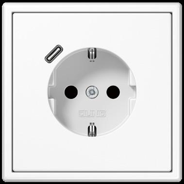 SCHUKO ® SOCKET WITH USB-C
Ref.-no.
SCHUKO® socket with USB charger with enhanced contact protection (shutter) with 1 USB port type A with quick charge function

Screwless terminals for wires up to 2.5 mm2
Installation in flush box according to EN 60670-1
installation depth: 48 mm
Thermoplastic (breakproof) high-gloss ivory
Thermoplastic (breakproof) lacquered
Technical data
Rated voltage: AC 220 ... 250 V ~
Mains frequency: 50/60 Hz
Rated current, socket: 16 A
Output voltage USB: DC 9 V / DC 5 V
Output current USB: 2 A / 3 A
Stand-by power: ≤ 60 mW
Ambient temperature: +5 ... +35 °C
Storage/transport temperature: −20 ... +70 °C

Installation depth: 48 mm
Protection level: IP 20
Connection mode: screwless connection single wire: 1.5 ... 2.5 mm2 stranded without ferrule: 1.5 ... 2.5 mm2
Ref.-no.
SCHUKO® socket with USB charger with enhanced contact protection (shutter) with 1 USB port type C with quick charge function
Screwless terminals for wires up to 2.5 mm2
Installation in flush box according to EN 60670-1
installation depth: 48 mm
Thermoplastic (breakproof) high-gloss
ivory A 1520-18 C
white
A 1520-18 C WW
black A 1520-18 C SW
Thermoplastic (breakproof) lacquered
aluminium
champagne
mocha
matt lacquered
matt snow white
matt graphite black
matt anthracite
Technical data
Rated voltage: AC 220 ... 250 V ~
Mains frequency: 50/60 Hz
Rated current, socket: 16 A
Output voltage USB: DC 9 V / DC 5 V
Output current USB: 2 A / 3 A
Stand-by power: ≤ 25 mW
Ambient temperature: +5 ... +35 °C
Storage/transport temperature: −20 ... +70 °C

Installation depth: 48 mm
Protection level: IP 20 Connection mode: screwless connection single wire: 1.5 ... 2.5 mm2 stranded without ferrule: 1.5 ... 2.5 mm2
A 1520-18 C AL
A 1520-18 C CH
A 1520-18 C MO
A 1520-18 C WWM
A 1520-18 C SWM
A 1520-18 C ANM
Ref.-no.
SCHUKO® socket with USB charger with enhanced contact protection (shutter) with 1 USB port type A and 1 USB port type C
Screwless terminals for wires up to 2.5 mm2
Installation in flush box according to EN 60670-1
installation depth: 48 mm
Thermoplastic (breakproof) high-gloss
ivory
white
A 1520-15 CA
A 1520-15 CA WW
black A 1520-15 CA SW
Thermoplastic (breakproof) lacquered
aluminium
champagne
mocha
matt lacquered
matt snow white
matt graphite black
matt anthracite
Technical data
Rated voltage: AC 220 ... 250 V ~
Mains frequency: 50/60 Hz
Rated current, socket: 16 A
Output voltage USB: DC 5 V
Output current USB (total): 3 A
Stand-by power: ≤ 25 mW
Ambient temperature: +5 ... +35 °C
Storage/transport temperature: −20 ... +70 °C

Installation depth: 48 mm
Protection level: IP 20
Connection mode: screwless connection single wire: 1.5 ... 2.5 mm2 stranded without ferrule: 1.5 ... 2.5 mm2
A 1520-15 CA AL
A 1520-15 CA CH
A 1520-15 CA MO
A 1520-15 CA WWM
A 1520-15 CA SWM
A 1520-15 CA ANM
Ref.-no.
Socket, French/Belgian system with USB charger
2-pole + male earth pin, 16 A / 250 V ~ with enhanced contact protection (shutter) with 1 USB port type A with quick charge function
Screwless terminals for wires up to 2.5 mm2
Installation in flush box according to EN 60670-1
installation depth: 48 mm
Thermoplastic (breakproof) high-gloss
white A 1520 F-18 A WW
ivory A 1520 F-18 A
black A 1520 F-18 A SW
Thermoplastic (breakproof) lacquered
aluminium A 1520 F-18 A AL
champagne A 1520 F-18 A CH
mocha A 1520 F-18 A MO
matt lacquered
matt graphite black A 1520F-18 A SWM
matt snow white A 1520F-18 A WWM
matt anthracite A 1520F-18 A ANM
Technical data
Rated voltage: AC 220 ... 250 V ~
Mains frequency: 50/60 Hz
Rated current, socket: 16 A

Output voltage USB: DC 9 V / DC 5 V
Output current USB: 2 A / 3 A
Stand-by power: ≤ 60 mW
Ambient temperature: +5 ... +35 °C
Storage/transport temperature: −20 ... +70 °C

Installation depth: 48 mm
Protection level: IP 20
Connection mode: screwless connection single wire: 1.5 ... 2.5 mm2 stranded without ferrule: 1.5 ... 2.5 mm2
Ref.-no.
Socket, French/Belgian system with USB charger
2-pole + male earth pin, 16 A / 250 V ~ with enhanced contact protection (shutter) with 1 USB port type C with quick charge function
Screwless terminals for wires up to 2.5 mm2
Installation in flush box according to EN 60670-1
installation depth: 48 mm
Thermoplastic (breakproof) high-gloss
Duroplastic lacquered
graphite black
Technical data
Rated voltage: AC 220 ... 250 V ~
Mains frequency: 50/60 Hz
Rated current, socket: 16 A

Output voltage USB: DC 9 V / DC 5 V
Output current USB: 2 A / 3 A
Stand-by power: ≤ 25 mW
Ambient temperature: +5 ... +35 °C
Storage/transport temperature: −20 ... +70 °C

Installation depth: 48 mm
Protection level: IP 20
Connection mode: screwless connection single wire: 1.5 ... 2.5 mm2 stranded without ferrule: 1.5 ... 2.5 mm2
Ref.-no.
Socket, French/Belgian system with USB charger
2-pole + male earth pin, 16 A / 250 V ~ with enhanced contact protection (shutter) with 1 USB port type A and 1 USB port type C
Screwless terminals for wires up to 2.5 mm2
Installation in flush box according to EN 60670-1
installation depth: 48 mm
Thermoplastic (breakproof) high-gloss
ivory A 1520 F-15 CA
white A 1520 F-15 CA WW
black A 1520 F-15 CA SW
Thermoplastic (breakproof) lacquered
aluminium A 1520 F-15 CA AL
champagne A 1520 F-15 CA CH
mocha A 1520 F-15 CA MO
matt lacquered
matt snow white A 1520F-15 CA WWM
matt graphite black A 1520F-15 CA SWM
matt anthracite A 1520F-15 CA ANM
Technical data
Rated voltage: AC 220 ... 250 V ~
Mains frequency: 50/60 Hz
Rated current, socket: 16 A
Output voltage USB: DC 5 V
Output current USB (total): 3 A
Stand-by power: ≤ 25 mW
Ambient temperature: +5 ... +35 °C
Storage/transport temperature: −20 ... +70 °C

Installation depth: 48 mm
Protection level: IP 20
Connection mode: screwless connection single wire: 1.5 ... 2.5 mm2 stranded without ferrule: 1.5 ... 2.5 mm2
Ref.-no.
SCHUKO® socket with USB charger with enhanced contact protection (shutter) with 1 USB port type A with quick charge function
Screwless terminals for wires up to 2.5 mm2
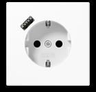
Installation in flush box according to EN 60670-1
installation depth: 48 mm
Thermoplastic (breakproof) high-gloss
ivory LS 1520-18 A
white LS 1520-18 A WW
light grey LS 1520-18 A LG
black LS 1520-18 A SW
matt lacquered
matt snow white LS 1520-18 A WWM
matt graphite black LS 1520-18 A SWM metal colours (thermoplastic lacquered)
aluminium (lacquered)
stainless steel (lacquered)
AL 1520-18 A-L
ES 1520-18 A-L
anthracite (lacquered) AL 1520-18 A AN-L dark (lacquered) AL 1520-18 A D-L
classic brass (lacquered)
antique brass (lacquered)
Technical data
Rated voltage: AC 220 ... 250 V ~
Mains frequency: 50/60 Hz
Rated current, socket: 16 A
Output voltage USB: DC 9 V / DC 5 V
Output current USB: 2 A / 3 A
Stand-by power: ≤ 60 mW
Ambient temperature: +5 ... +35 °C
Storage/transport temperature: −20 ... +70 °C

Installation depth: 48 mm
Protection level: IP 20
Connection mode: screwless connection single wire: 1.5 ... 2.5 mm2
stranded without ferrule: 1.5 ... 2.5 mm2
ME 1520-18 A C-L
ME 1520-18 A AT-L
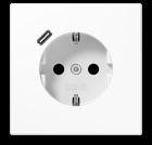
Ref.-no.
SCHUKO® socket with USB charger with enhanced contact protection (shutter) with 1 USB port type C with quick charge function
Screwless terminals for wires up to 2.5 mm2
Installation in flush box according to EN 60670-1
installation depth: 48 mm
Thermoplastic (breakproof) high-gloss
ivory LS 1520-18 C
white LS 1520-18 C WW
light grey LS 1520-18 C LG
black LS 1520-18 C SW
matt lacquered
matt snow white LS 1520-18 C WWM
matt graphite black LS 1520-18 C SWM
metal colours (thermoplastic lacquered)
aluminium (lacquered)
stainless steel (lacquered)
anthracite (lacquered)
dark (lacquered)
classic brass (lacquered)
antique brass (lacquered)
Technical data
Rated voltage: AC 220 ... 250 V ~
Mains frequency: 50/60 Hz
Rated current, socket: 16 A
Output voltage USB: DC 9 V / DC 5 V
Output current USB: 2 A / 3 A
Stand-by power: ≤ 25 mW
Ambient temperature: +5 ... +35 °C
Storage/transport temperature: −20 ... +70 °C

Installation depth: 48 mm
Protection level: IP 20
Connection mode: screwless connection single wire: 1.5 ... 2.5 mm2 stranded without ferrule: 1.5 ... 2.5 mm2
AL 1520-18 C-L
ES 1520-18 C-L
AL 1520-18 C AN-L
AL 1520-18 C D-L
ME 1520-18 C C-L
ME 1520-18 C AT-L
Ref.-no.
SCHUKO® socket with USB charger with enhanced contact protection (shutter) with 1 USB port type A and 1 USB port type C
Screwless terminals for wires up to 2.5 mm2
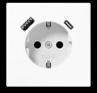
Installation in flush box according to EN 60670-1
installation depth: 48 mm
Thermoplastic (breakproof) high-gloss
ivory LS 1520-15 CA
white LS 1520-15 CA WW
light grey LS 1520-15 CA LG
black LS 1520-15 CA SW
matt lacquered
matt snow white
LS 1520-15 CA WWM
matt graphite black LS 1520-15 CA SWM
metal colours (thermoplastic lacquered)
aluminium (lacquered)
stainless steel (lacquered)
anthracite (lacquered)
dark (lacquered)
classic brass (lacquered)
antique brass (lacquered)
Technical data
Rated voltage: AC 220 ... 250 V ~
Mains frequency: 50/60 Hz
Rated current, socket: 16 A
Output voltage USB: DC 5 V
Output current USB (total): 3 A
Stand-by power: ≤ 25 mW
Ambient temperature: +5 ... +35 °C
Storage/transport temperature: −20 ... +70 °C
Installation depth: 48 mm
Protection level: IP 20
Connection mode: screwless connection single wire: 1.5 ... 2.5 mm2
stranded without ferrule: 1.5 ... 2.5 mm2
AL 1520-15 CA-L
ES 1520-15 CA-L

AL 1520-15 CA AN-L
AL 1520-15 CA D-L
ME 1520-15 CA C-L
ME 1520-15 CA AT-L
Socket, French/Belgian system with USB charger
2-pole + male earth pin, 16 A / 250 V ~ with enhanced contact protection (shutter) with 1 USB port type A with quick charge function

Screwless terminals for wires up to 2.5 mm2
Installation in flush box according to EN 60670-1
installation depth: 48 mm
Thermoplastic (breakproof) high-gloss

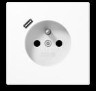
Socket, French/Belgian system with USB charger with enhanced contact protection (shutter) with 1 USB port type C with quick charge function
Screwless terminals for wires up to 2.5 mm2
Installation in flush box according to EN 60670-1
2-pole + male earth pin, 16 A / 250 V ~ installation depth: 48 mm
Thermoplastic (breakproof) high-gloss
lacquered
graphite black
metal colours (thermoplastic lacquered)
(lacquered)
steel (lacquered)
brass (lacquered)
brass (lacquered)
Technical data
Rated voltage: AC 220 ... 250 V ~
Mains frequency: 50/60 Hz
Rated current, socket: 16 A
Output voltage USB: DC 9 V / DC 5 V
Output current USB: 2 A / 3 A
Stand-by power: ≤ 25 mW
Ambient temperature: +5 ... +35 °C
Storage/transport temperature: −20 ... +70 °C

Installation depth: 48 mm
Protection level: IP 20
Connection mode: screwless connection single wire: 1.5 ... 2.5 mm2 stranded without ferrule: 1.5 ... 2.5 mm2
Socket, French/Belgian system with USB charger
2-pole + male earth pin, 16 A / 250 V ~ with enhanced contact protection (shutter) with 1 USB port type A and 1 USB port type C
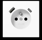
Screwless terminals for wires up to 2.5 mm2
Installation in flush box according to EN 60670-1
installation depth: 48 mm
Thermoplastic (breakproof) high-gloss
Technical data

Rated
Rated current, socket: 16 A
Output current USB (total): 3 A
Ref.-no.
USB charger with 1 USB port type A and 1 USB port type C screw fixing only, without claws
white USB 15 CA WW black USB 15 CA SW
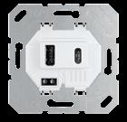
Intended use
• Battery charging station for mobile devices with USB connection
• Installation in flush box according to EN 60670-1
Product characteristics
• Simultaneous charging of 2 devices possible
• Installation into multiple frame with other devices possible
• Charging current: max. 3000 mA
Technical data
Input voltage: AC 100 ... 240 V ~ ± 10 %
Mains frequency: 50/60 Hz
Ambient temperature: 0 ... +35 °C
Storage/transport temperature: −20 ... +70 °C

Stand-by power consumption at UIN = 230 V ~: ≤ 0.1 W
Connection mode: screw terminals
Output voltage: DC 5 V (± 5 %)
Output current
AC 120 ... 240 V ~ max. 3000 mA
AC 90 ... 108 V ~ max. 2500 mA
Ref.-no.
Centre plate


for USB charger ref.-no.: USB 15 CA WW, USB 15 CA SW
for AS range
Thermoplastic (breakproof) high-gloss
ivory
white
for A range
Thermoplastic (breakproof) high-gloss
white
black
Thermoplastic (breakproof) lacquered
aluminium
champagne
L A 1569 USB
L A 1569 USB WW
L A 1569 USB WW
L A 1569 USB SW
P L A 1569 USB AL
P A 1569 USB CH

mocha A 1569 USB MO
matt lacquered
matt snow white A 1569 USB WWM
matt graphite black A 1569 USB SWM
matt anthracite A 1569 USB ANM
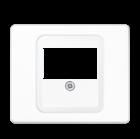
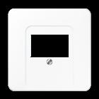
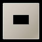
Centre plate
for USB charger ref.-no.: USB 15 CA WW, USB 15 CA SW
for CD range
Thermoplastic (breakproof) high-gloss

metal versions (anodized aluminium)
for SL range
for LS range
Thermoplastic (breakproof) high-gloss ivory
light grey
matt lacquered matt snow white
1969 USB WWM matt graphite black
metal versions aluminium
stainless steel
1969 USB SWM
ES 1969 USB
1969 USB AN dark (aluminium lacquered)
anthracite (aluminium lacquered)
classic brass
antique brass
1969 USB D
ME 1969 USB C
1969 USB AT

Ref.-no.
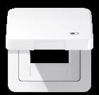
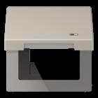
Hinged lid
with symbol "charger"

for USB charger ref.-no.: USB 15 CA WW, USB 15 CA SW including centre plate
for CD range
Thermoplastic (breakproof) high-gloss
ivory CD 590 KL USB

white
brown
grey
light grey
black
metal versions (anodized aluminium)
gold-bronze
platinum
for LS range with spring
Thermoplastic (breakproof) high-gloss
CD 590 KL USB WW
CD 590 KL USB BR
CD 590 KL USB GR
CD 590 KL USB LG
CD 590 KL USB SW
CD 590 KL USB GB
CD 590 KL USB PT
ivory LS 990 BFKL USB
white
light grey
LS 990 BFKL USB WW
LS 990 BFKL USB LG
black LS 990 BFKL USB SW
metal versions
aluminium
stainless steel
anthracite (aluminium lacquered)
dark (aluminium lacquered)
classic brass
antique brass
AL 2990 KL USB
ES 2990 KL USB
AL 2990 KL USB AN
AL 2990 KL USB D
ME 2990 KL USB C
ME 2990 KL USB AT
Highest sound quality: digital radio in the switch design with real glass front and sensor buttons – also with Bluetooth streaming on request.
 SMART RADIO DAB+
The Smart Radio DAB+ is impressive with its digital sound experience and best reception quality. Up to eight DAB+ favourites and eight USW favourites can be saved and retrieved via shortcut. The version with Bluetooth function also allows up to eight Bluetooth audio sources

to be stored and played back – this means radio and streaming functions in a single compact device. Display and button brightness can be adjusted in both versions and are completely darkened in night mode.
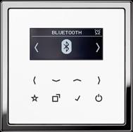

 Smart Radio DAB+ in LS 990 black with stainless steel frame, mono version.
Smart Radio DAB+ Bluetooth with two loudspeakers in separate mounting. LS 990 design in white with chrome frame.
Smart Radio DAB+
for installation in single or multiple frames and surface caps
Intended use
• DAB reception in the frequency range 174 MHz to 240 MHz (VHF band III and channel 13)
• FM reception in the frequency range 87.5 MHz to 108 MHz (VHF band II)
• Installation in flush box according to EN 60670-1 (recommendation: deep box)
Product characteristics
• Digital radio with display and sensor buttons
• Real glass front panel
• Stereo reception
• Connection terminals for two loudspeakers
• Stereo/mono switch-over
• Simple operation
• Integrated antenna for DAB+ and FM
• High reception quality
• Automatic station scan
• Storage of 8 favourites DAB+ and 8 favourites FM (will be retained after power failure)
• Switch-on with last station
• Switch-on with last volume
• Switch-on with last operation mode (DAB+ or FM)
• Display of station information, time and current settings
• Current time via RDS and DAB+
• Brightness level of display can be adjusted
• Night mode
• Alarm function
• Sleep mode
• Switching on/off via extension unit
• Line-out output (AUX) to connect external amplifiers
• Optional external cable antenna ref.-no.: RAD-ANT
Satellite function
The radio is equipped with a satellite input to connect an external switch.
Technical data
Rated voltage: AC 230 V ~
Mains frequency: 50/60 Hz
Connection: screw terminals
Terminals for: 1 x 2.5 mm2 or 1 x 1.5 mm2
Power consumption stand-by: < 1 W
Power consumption during operation: < 4 W
Temperature range: 0 ... +50 °C
Atmospheric humidity: 15 ... 90 % (no condensation)

DAB frequency range: 174 ... 240 MHz
FM frequency range: 87.5 ... 108 MHz
Separate loudspeaker connection cable: Twin loudspeaker cable H03VH-H, 2 x 0.75 mm
Alternative: J-Y(St)Y 2 x 2 x 0.6 mm
Length of connected cable: max. 5 m
Ref.-no.
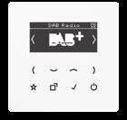
Smart Radio DAB+


for AS and A ranges
white DAB A WW
black DAB A SW
for CD range
white DAB CD WW
black DAB CD SW
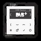
for LS range
white DAB LS WW
black DAB LS SW
External cable antenna

RAD-ANT for connection to the Smart Radio DAB+ ref.-no. DAB .. and DAB .. BT ..
Ref.-no.
Power supply for the Smart Radio DAB+ ref.-no. DAB .. and DAB .. BT .. (Spare part)
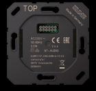
NT-AUDIO
Display for the Smart Radio DAB+ ref.-no. DAB .. (Spare part)
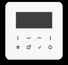

for AS and A ranges
white DAB A-DISP WW
black DAB A-DISP SW
for CD range
white DAB CD-DISP WW
black DAB CD-DISP SW
for LS range
white DAB LS-DISP WW
black DAB LS-DISP SW
Ref.-no.
Smart Radio DAB+, mono set including power supply with one loudspeaker
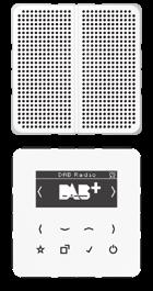
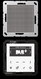
for AS and A ranges with white display
loudspeaker white DAB A1 WW
for CD range with white display
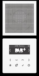
loudspeaker white DAB CD1 WW
for LS range with white display

loudspeaker white DAB LS1 WW with black display
loudspeaker black DAB LS1 SW
loudspeaker aluminium DAB AL1
loudspeaker stainless steel DAB ES1
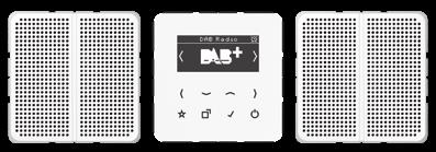

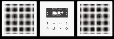

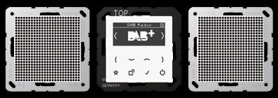


Smart Radio DAB+, stereo set including power supply with two loudspeakers
for AS and A ranges with white display loudspeaker white
for CD range with white display loudspeaker white
for LS range with white display
loudspeaker white
loudspeaker black
loudspeaker aluminium
loudspeaker stainless steel
DAB
WW with black display
DAB
Smart Radio DAB+ Bluetooth
for installation in single or multiple frames and surface caps
Intended use
• DAB reception in the frequency range 174 MHz to 240 MHz (VHF band III and channel 13)
• FM reception in the frequency range 87.5 MHz to 108 MHz (VHF band II)
• Playback and control of music on mobile devices via Bluetooth

• Installation in flush box according to EN 60670-1 (recommendation: deep box)
Product characteristics
• Digital radio with display and sensor buttons
• Real glass front panel
• Stereo reception
• Connection terminals for two loudspeakers
• Stereo/mono switch-over
• Simple operation
• Integrated antenna for DAB+ and FM
• High reception quality
• Automatic station scan
• Storage of 8 favourites DAB+ and 8 favourites FM (will be retained after power failure)
• Storage of 8 Bluetooth audio sources
• Bluetooth device name can be changed
• Switch-on with last station
• Switch-on with last volume
• Switch-on with last operation mode (DAB+, FM or Bluetooth)
• Display of station information, time and current settings
• Current time via RDS and DAB+
• Brightness level of display can be adjusted
• Night mode
• Alarm function
• Sleep mode
• Switching on/off via extension unit
• Line-out output (AUX) to connect external amplifiers
• Optional external cable antenna ref.-no.: RAD-ANT
Satellite function
The radio is equipped with a satellite input to connect an external switch.
Technical data
Rated voltage: AC 230 V ~
Mains frequency: 50/60 Hz
Connection: screw terminals
Terminals for: 1 x 2.5 mm2 or 1 x 1.5 mm2
Power consumption stand-by: < 1 W
Power consumption during operation: < 4 W
Temperature range: 0 ... +50 °C
Atmospheric humidity: 15 ... 90 % (no condensation)
DAB frequency range: 174 ... 240 MHz
FM frequency range: 87.5 ... 108 MHz
Bluetooth: A2DP, AVRCP
Radio frequency: 2.402 ... 2.480 GHz
Transmitting power: < 4 dBm
Separate loudspeaker connection cable: Twin loudspeaker cable H03VH-H, 2 x 0.75 mm
Alternative: J-Y(St)Y 2 x 2 x 0.6 mm
Length of connected cable: max. 5 m

Ref.-no. Smart Radio DAB+ Bluetooth for AS and A ranges white
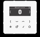

for CD range
for LS range
External cable antenna
for connection to the Smart Radio DAB+ ref.-no. DAB .. and DAB .. BT ..

Power supply for the Smart Radio DAB+ ref.-no. DAB .. and DAB .. BT .. (Spare part)
Ref.-no.
NT-AUDIO
Display
for the Smart Radio DAB+ Bluetooth ref.-no. DAB .. BT .. (Spare part)
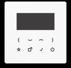
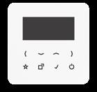

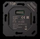

for AS and A ranges
white
for CD range
white
for LS range
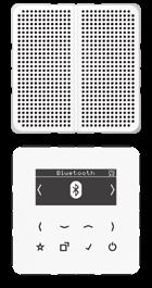
Ref.-no.
Smart Radio DAB+ Bluetooth, mono set including power supply with one loudspeaker
for AS and A ranges with white display
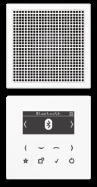
loudspeaker white
DAB A1 BT WW
for CD range with white display
loudspeaker white
DAB CD1 BT WW
for LS range with white display
loudspeaker white
DAB LS1 BT WW with black display
loudspeaker black
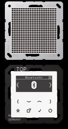
loudspeaker aluminium
loudspeaker stainless steel
DAB LS1 BT SW
DAB AL1 BT
DAB ES1 BT

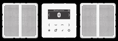
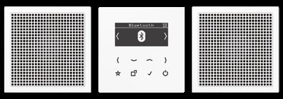

Smart Radio DAB+ Bluetooth, stereo set including power supply with two loudspeakers
for AS and A ranges with white display


loudspeaker white
for CD range with white display
loudspeaker white
for LS range with white display
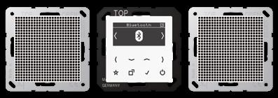
loudspeaker white
with black display
loudspeaker black
loudspeaker aluminium
loudspeaker stainless steel
Loudspeaker module

for connection to the Smart Radio DAB+ ref.-no. DAB .. and DAB .. BT .. high-quality tone and great loudspeaker dynamics optimised acoustics through the use of a bass-reflex enclosure
Technical data
Rated nominal power: approx. 2.5 W
Impedance: 4 Ω
Frequency range: 120 ... 15 000 Hz (−10 dB)

Relative humidity: max. 95 %

Storage/transport temperature: −25 ... +60 °C
Connection: screw terminals
Terminals for: 1.5 mm2
for AS and A ranges
Thermoplastic (breakproof) high-gloss
(breakproof) lacquered
for CD range Thermoplastic (breakproof) high-gloss
for LS range
Thermoplastic (breakproof) high-gloss
lacquered)
Whether classic stand-alone solution or networked by radio: JUNG smoke alarm devices have been reliably raising the alarm for smoke and heat development for many years. The integrated lithium battery has a service life of more than 10 years. All JUNG smoke alarm devices can be installed quickly and without dirt thanks to the certified magnet / adhesive system.


 Alarm relay with floating input
Smoke alarm device RWM 200 in black
Radio smoke alarm device FRWM 200 in white
Radio smoke alarm device FRWM 200 in black
Smoke alarm device / Observers
Ref.-no.
Smoke alarm device
black RWM 200 SW
Intended use
• Detection of smoke and heat in private households and inhabited properties
• Smoke alarm device for indoor use
• Installation in inhabitable recreation vehicles (e.g. caravans) possible
Product characteristics
• Replaceable insect screen

• Lithium battery with protective passivation
• 12 years battery life
• Bi-sensor processor technology (smoke + heat)
• Real alarm with maximum precision
• Qualified for kitchens
• 88 dB alarm signal at 3 m distance
• Dimensions (Ø x H): 10 x 3.8 cm
• Detection range: up to 60 m2 (depending on installation location)
• Optimum storing temperature: +10 ... +35 °C, <70 % relative humidity

• Large user-friendly test/stop button (78 cm2)
• Magnetic mount for adhesive fixing or screw fixing
• Complies with the increased requirements vfdb Directive 14-01
• CE according to EN 14604:2005/AC:2008
• TüV Nord Cert (Kriwan no. 1772-CPR-150500)
Insect screen
Set of 48 insect screens and 96 seals (Spare part)
for smoke alarm devices ref.-no.: .. RWM 200 ..

Magnet holder set (Spare part)
for smoke alarm devices ref.-no.: .. RWM ..
RWM 200-G
RWM-MTS
Radio smoke alarm device
Intended use
• Detection of smoke and heat in private households and inhabited properties
• Smoke alarm device for indoor use


• Installation in inhabitable recreation vehicles (e.g. caravans) possible
Product characteristics
• Radio connectivity
• Frequency: 868.3 MHz
• Data encryption: AES-256
• Max. number of devices per group: 15
• Community group (stair case): assigment of up to 14 groups (apartments)
• Radio range: 400 m, ±10 % (free field)
• Repeater function
• Replaceable insect screen
• Lithium battery with protective passivation
• 10 years battery life
• Bi-sensor processor technology (smoke + heat)
• Real alarm with maximum precision
• Qualified for kitchens
• 88 dB alarm signal at 3 m distance
• Dimensions (Ø x H): 10 x 3.8 cm
• Detection range: up to 60 m2 (depending on installation location)
• Optimum storing temperature: +10 ... +35 °C, <70 % relative humidity

• Large user-friendly test/stop button (78 cm2)
• Magnetic mount for adhesive fixing or screw fixing
• Complies with the increased requirements vfdb Directive 14-01
• CE according to EN 14604:2005/AC:2008
Alarm relay with floating input for interconnected radio smoke alarm devices ref.-no.: FRWM ..
Intended use
• Wireless integration into group of radio smoke alarm devices
• Relay output to trigger acoustical or optical signals, ventilation systems, blind systems etc. in case of an alarm in the radio group
• Floating input for manual triggering of an alarm in the radio group via switch
Product characteristics
• Battery-powered device
• Battery life up to 10 years (lithium battery)
• Frequency: 868.3 MHz
• Data encryption: AES-256
• Buzzer alarm
• Status LED
• Radio range: approx. 400 m (free field)
• Floating alarm input, max. 30 V, switching threshold approx. 6 V
• Alarm output: relay (2-way), 3 ... 30 V, 1 ... 100 mA
• Dimensions approx. 54 x 54 x 22 mm
The observers are impressive in their performance and functionality. In outdoor applications, they provide the optimum solution for almost all applications.
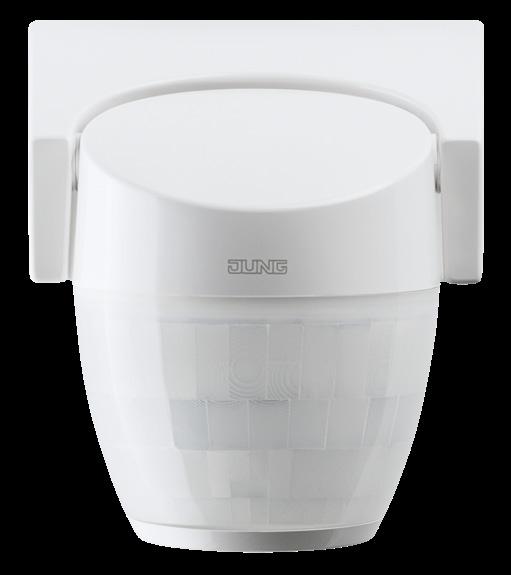
Not suitable for alarm systems!
Mounting height: 2.40 m
Observer 220° with digital signal evaluation
Intended use
Ref.-no.
• Automatic switching of lighting depending on the thermal movement and ambient brightness
• Surface-mounting in indoor and outdoor areas
Product characteristics
• Digital signal evaluation
• Protected against spray water
• Run-on time adjustable
• Sensitivity selectable
• Brightness value can be set
• Test operation for checking the detection area
• Switch light ON or OFF for 4 hours
• Short-time operation to control signal encoders
• Sensor head adjustable in 2 axes
• Self-adhesive cover plate elements for limiting the detection area
• High protection against ambient light
• 580 switching segments in 4 layers
• Separate protection against crawling under
• Parallel connection of multiple motion detectors possible
• Manual switch-on possible with installation button, NC contact
Important: Energy saving lamps cause high inrush currents which may cause the switch contact to get stuck. Then a reduction of capacity is required! Please check suitability of lamps before installation. Delay time limitation: Once the detector has switched on, the brightness is no longer evaluated. To prevent the light from remaining permanently on (e.g. beyond dawn) caused by permanent movements, the device is provided with an intelligent limiting function.
The delay time (time the light remains on after detection of the last movement) is selected depending on the real switch-on time:
Switch-on time (approx.) / Delay time (approx.) up to 60 min / depending on setting up to 70 min / 4 min up to 75 min / 2 min up to 80 min / 1 min up to 85 min / 30 sec up to 90 min / 15 sec 90 min / switching-off
The detector switches off after 90 minutes, at the latest, even if there are still movements in the detection field. Restarting will only be effected if the ambient brightness drops below the preset brightness level and if a movement is detected in the detection field.
Technical data
Nominal range: approx. 16 m
Mounting height: approx. 2.4 m
Detection range: approx. 220°, with separate undercrawling protection
Rated voltage: AC 230 V ~, 50/60 Hz
Switch contact: relay, mains potential
Switch-on current: max. 20 A
Circuit breaker: 16 A
Power consumption: approx. 1.1 W
Temperature range: −20 ... +55 °C
Shut-off delay: 2 s ... 30 min, continuously adjustable short-time pulse 0.5 s
Brightness sensor: Daytime and night-time operation approx. 1 ... 1,000 lx, continuously adjustable

Sensitivity: approx. 20 ... 100 %, continuously adjustable
Protection level: IP 55
Terminals: L, N, μ (relay) wiring up to 2.5 mm2
Switching capacity
Incandescent lamps: 2300 W
HV halogen lamps: 2300 W
LV halogen lamps with electronic transformers: 1200 W inductive transformers: 1200 W
Operate inductive transformers with at least 85 % nominal load.
Fluorescent lamps non-compensated: 1200 W parallel compensated: 920 W lead-lag circuit: 2300 W
The emergency signal can e.g. be installed outside next to the WC door or landing door. A triggered emergency call is signalled visually by a red LED and acoustically by a buzzer, 90 dB(A). Both signals can, if required, be changed from continuous light/continuous tone to flashing light/pulsing tone.
The reset button is installed next to the door in the same room as the pull cord push-button. The assisting personnel can reset the triggered call.
Power supply for the emergency call system with DC 24 V.
The emergency signal can e.g. be installed outside next to the WC door or landing door. A triggered emergency call is signalled visually by a red LED and acoustically by a buzzer, 90 dB(A). Both signals can, if required, be changed from continuous light/continuous tone to flashing light/pulsing tone.



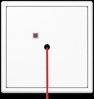
The JUNG emergency system is a well-conceived, complete set for emergency calls in WCs or en-suite bathrooms in old people’s homes and nursing homes or WC facilities in public buildings. It ensures that a person in need of help can sound the alarm in an emergency and meets all the safety-related requirements in accordance with DIN VDE 0834. The emergency system is available for the AS / A, CD and LS design ranges to complete a unique design in a building.
 CALL BUTTON
Hospital installations
Ref.-no. Emergency system set consists of pull cord push-button, emergency signal, reset button and power supply screw fixing only, without claws with 1-gang frames for AS range
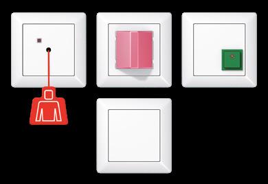
ivory
white
AS 0834 WW for CD range
white
CD 0834 WW for LS range
ivory
white
light grey
black
Single components (spare parts):


Pull cord push-button screw fixing only, without claws without frame
for AS and A ranges
Thermoplastic (breakproof) high-gloss
ivory
AS 0834 ZT
AS 0834 ZT WW for CD range
white
Thermoplastic (breakproof) high-gloss
white
CD 0834 ZT WW for LS range
Thermoplastic (breakproof) high-gloss
ivory
white
light grey
black
pull cord ref.-no.: ZS-34 KO5S included
LS 0834 ZT
LS 0834 ZT WW
LS 0834 ZT LG
LS 0834 ZT SW
Pull cord length: approx. 2000 mm with spring hook red ZS-34 KO5S

Emergency signal

screw fixing only, without claws without frame for AS and A ranges
Thermoplastic (breakproof) high-gloss
ivory
white NRS AS 0834 RM WW for CD range
Thermoplastic (breakproof) high-gloss
white NRS CD 0834 RM WW for LS range
Thermoplastic (breakproof) high-gloss
ivory
white
light grey
Reset button screw fixing only, without claws without frame for AS and A ranges

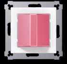
Thermoplastic (breakproof) high-gloss
ivory
for CD range
Thermoplastic (breakproof) high-gloss
for LS range
Thermoplastic (breakproof) high-gloss
Power supply screw fixing only, without claws without frame supplies the emergency call system with DC 24 V for AS and A ranges
Thermoplastic (breakproof) high-gloss ivory
for CD range
Thermoplastic (breakproof) high-gloss white
for LS range
Thermoplastic (breakproof) high-gloss
Optional:
Service unit screw fixing only, without claws without frame for AS and A ranges
Thermoplastic (breakproof) high-gloss
for CD range
Thermoplastic (breakproof) high-gloss
DZE
DZE WW for LS range
Thermoplastic (breakproof) high-gloss
Service terminal
Thermoplastic (breakproof) high-gloss
• Central remote signalling from up to 20 alarms
• Optical and acoustical signalling
• Two-line display for indication of the alarms
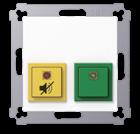
• Programmable alarm messages with up to 16 characters for allocating the alarms
• 20 electrically isolated inputs with one ground
• Evaluation of standby- and operating current
• Suppression of the acoustical alarms for 20 seconds
• Green presence push-button
• Yellow alarm suppression push-button

• Programmable with the PC
• USB-cable and Software (multi-language) included
• Power supply 24 V DC
• Inputs 24 V DC
• For screw-fixing in a wall box without claws
• Dimensions: 145 x 100 x 24 mm (H x W x D)
Technical data
Supply voltage: DC 24 V ± 12.5 %
Current consumption: max. 30 mA
Ambient temperature: +5 ... +40 °C
Connection mode: screwless connection single wire: Ø 0.3 ... 1.4 mm
Cable type: J-Y(St)Y
Distance emergency signal – service terminal: max. 500 m

Inputs Voltage range: DC 24 V ± 12.5 %
Current consumption: typical 2 mA
Surface-mounted housing for service terminal ref.-no.: NRS DZT 20 WW

Thermoplastic (breakproof) high-gloss white NRS DZT AP WW
Dimensions: 100 x 145 x 25 mm (W x H x D)

Call button
screw fixing only, without claws without frame
An additional control for triggering an emergency call for AS and A ranges
Thermoplastic (breakproof) high-gloss
for CD range
Thermoplastic (breakproof) high-gloss
for LS range
Thermoplastic (breakproof) high-gloss
“Oversize rockers” made of stainless steel, for convenient operation of automatic doors: ideal for use in corridors in hospitals and care homes where beds and wheelchairs have to be pushed.

Installation note: No plaster compensation possible. Insert must be mounted flush with the wall. Supporting frame must be on top of wallpaper.
Ref.-no.
Oversize rocker (70 x 212.4 mm) for switch insert ref.-no.: 501 U, 502 U, 503 U, 506 U, 507 U, 501-20 U, 506-20 U, 507-20 U for push switch insert ref.-no.: 502 TU, 506 TU, 507 TU for push-button insert ref.-no.: 531 U, 532 U, 533 U, 533-2 U
stainless steel
IP L ES 2993 white (stainless steel lacquered)
IP P ES 2993 WW


Protection level IP 44 only possible with 3-gang frame!
Inscription on request
Oversize rocker (70 x 212.4 mm) with lens for switch insert with indicator light ref.-no.: 502 KOU, 503 KOU, 506 KOU, 501-20 KOU, 502-20 KOU, 506-20 KOU for push switch insert with indicator light ref.-no.: 502 KOTU, 506 KOTU for push-button insert ref.-no.: 531 U, 533 U, 533-2 U, 534 U
stainless steel
IP L ES 2993 KO5 white (stainless steel lacquered)
IP ES 2993 KO5 WW
Protection level IP 44 only possible with 3-gang frame!
Inscription on request
Holder plate for frame fixing and oversize rocker bearing (Spare part)
black ES 2993 HP
Installation note: No plaster compensation possible. Insert must be mounted flush with the wall. Supporting frame must be on top of wallpaper.
Surface cap with integrated frame and non-flammable ground plate

3-gang, 223 x 81 x 47 mm metal colours (duroplastic lacquered) stainless steel (lacquered)
Duroplastic (scratch-proof) glossy
white
Ref.-no.
ES 2583 A-L
LS 583 A WW
Frame for horizontal and vertical installation
stainless steel
3-gang 81 x 223 mm
IP ES 2983 white (stainless steel lacquered)

3-gang 81 x 223 mm
IP ES 2983 WW

3-gang
Ref.-no.

583 A

for cable and mini trunking white 11 WW stone grey 11 SG for trunking 15 x 15 mm white 12 WW stone grey 12 SG for pipes with


outside Ø 16 mm
IP 551 WU
Accessories
Corridor unit
The integration of card readers in the JUNG system can also be realised in the project.
A good hotel is perfectly coordinated in its processes and provides its guests with a high degree of service and comfort. The well thought-out and proven hospitality solutions from JUNG help both guests and hotel personnel. The intuitive operating philosophy for
controlling room functions and automated processes is an essential factor here. Only then does the guest feel comfortable. In addition, the necessary routines can be created in the daily work of the hotel personnel.
High comfort for the guest, more economic efficiency for the owner and efficient work processes for the personnel. This is what the professional hotel installations from JUNG stand for.
 TEMPERATURE CONTROLLER WITH FAN COIL
Ref.-no.
1-gang push-button insert 10 A / 250 V ~
Screwless terminals for wires up to 2.5 mm2 Without claws: ref.-no. with additional "E", e.g.: 531 EU
1-pole, 1-way (NO contact) 531 U
1-pole, 2-way with terminal for N conductor 533 U
1-pole, 1-way (NO contact) with separate contacts for indicator light 534 U
Illumination possible with lamp ref.-no. 90/95 (230 V), 96-.. (low voltage), or LED lamp ref.-no. 90-LED.. (230 V) or 961248 LED.. (low voltage).
1-gang push-button insert 10 A / 250 V ~

Screwless terminals for wires up to 2.5 mm2 Without claws: ref.-no. with additional "E", e.g.: 532 EU
2-pole, 1-way (NO contact) 532 U
Key card holder for push-button insert ref.-no.: 531 U, 532 U, 533 U, 534 U
The key card holder is used to keep the hotel card and to ensure a high level of safety and energy savings, since all possibly powered electrical loads are switched off automatically when removing the hotel card.

The key card holder will be completed with a push-button of the JUNG portfolio.
The push-button ref.-no. 533 U with NO/NC contact and additional N-terminal is recommended.
The separate N-terminal enables the illumination of the device with incandescent or LED lamp at the same potential. If the pilot lamp should not be at the same potential, please install the push-button ref.-no. 534 U with separate signalling contact.
Installation note: No plaster compensation possible. Insert must be mounted flush with the wall. Supporting frame must be on top of wallpaper.
for AS and A ranges
Thermoplastic (breakproof) high-gloss
ivory
white
black
Thermoplastic (breakproof) lacquered
aluminium
champagne
mocha
matt lacquered
matt snow white
matt graphite black
matt anthracite
A 590 CARD

A 590 CARD WW
A 590 CARD SW

A 590 CARD AL
A 590 CARD CH
A 590 CARD MO
A 590 CARD WWM
A 590 CARD SWM
A 590 CARD ANM
Ref.-no.
Key card holder

for push-button insert ref.-no.: 531 U, 532 U, 533 U, 534 U
for CD range
Thermoplastic (breakproof) high-gloss
white CD 590 CARD WW
metal colours (thermoplastic lacquered)
gold-bronze CD 590 CARD GB-L
platinum CD 590 CARD PT-L
for SL range
white SL 590 CARD WW
gold-bronze SL 590 CARD GB
black SL 590 CARD SW
for LS range
Thermoplastic (breakproof) high-gloss
ivory LS 590 CARD
white LS 590 CARD WW
light grey LS 590 CARD LG
black LS 590 CARD SW
matt lacquered
matt snow white LS 590 CARD WWM
matt graphite black LS 590 CARD SWM
metal colours (thermoplastic lacquered)
aluminium (lacquered)
stainless steel (lacquered)
anthracite (lacquered)
dark (lacquered)
classic brass (lacquered)
antique brass (lacquered)
AL 2990 CARD
ES 2990 CARD
AL 2990 CARD AN
AL 2990 CARD D
ME 2990 CARD C
ME 2990 CARD AT

Ref.-no.
Energy saving unit for key card holder RFID ref.-no.: .. CARD RFID ..
The intended use and the product features refer to the complete device, consisting of energy saving unit and key card holder RFID.
Intended use
• Switching of lighting and other loads
• Triggering of external control systems
• Installation in flush box according to EN 60670-1
Product characteristics
ESU 230-2
• Operation with RFID cards according to RFID standard ISO/IEC 14443 and ISO/IEC 15693
• 2 NO contacts, one of them with configurable run-on time

• Status indication with RGB lens
• Lens is dimming down 30 s after inserting the card
• Run-on time is signalled by RGB lens after removing the card

Technical data
Rated voltage: AC 110 ... 230 V ~
Mains frequency: 50/60 Hz
Switching current AC1 (cos ϕ > 0.8): 16 A
Current carrying capacity of device (A1 + A2): max. 16 A
Switch type: 2 NO contacts
Contact type: µ
Ambient temperature: −5 ... +45 °C
Storage/transport temperature: −25 ... +75 °C
Stand-by power: max. 0.94 W
Connection mode: screw terminals single wire: 1 x 2.5 mm2 or 2 x 1.5 mm2
Connected load, 230 V
Output 1 (A1)
Ohmic: 3000 W
Motors: 1160 VA
HV halogen lamps: 1000 W
Electronic transformers with LV halogen lamps: 1000 W
Output 2 (A2)
Shut-off delay: 0 ... 240 s (60 s)
Ohmic: 3000 W
Capacitive: 16 A / 140 µF
Motors: 1380 VA
HV halogen lamps: 2500 W
Electronic transformers with LV halogen lamps: 1500 W
Inductive transformers with LV halogen lamps: 1200 VA
HV LED lamps: typical 400 W
Reduction of load for every 5 °C exceededing 35 °C: −10 % for installation into wooden or hollow walls: −15 % for installation into multiple combinations: −20 %
Key card holder RFID
for energy saving unit ref.-no.: ESU 230-2

The key card holder RFID is used to keep the hotel card and to ensure a high level of safety and energy savings, since all possibly powered electrical loads are switched off with an adjustable delay after removing the hotel card. The key card holder RFID will be completed with the energy saving unit. The lens colour and brightness and the shut-off delay of the second relay can be adjusted at www.jung.de/hotelcard prior to placing an order.
The intended use and the product features refer to the complete device, consisting of energy saving unit and key card holder RFID.
Product characteristics
• Operation with RFID cards according to RFID standard ISO/IEC 14443 and ISO/IEC 15693
• 2 NO contacts, one of them with configurable run-on time

• Status indication with RGB lens
• Lens is dimming down 30 s after inserting the card
• Run-on time is signalled by RGB lens after removing the card
for A range
Thermoplastic (breakproof) high-gloss
white L
black
Thermoplastic (breakproof) lacquered
aluminium
mocha
matt
matt
for LS range
Thermoplastic (breakproof) high-gloss

ivory
white
light grey
L LS CARD RFID
L LS CARD RFID WW
L LS CARD RFID LG
black LS CARD RFID SW
matt lacquered
matt snow white LS CARD RFID WWM
matt graphite black LS CARD RFID SWM
metal colours (thermoplastic lacquered)
aluminium (lacquered)
stainless steel (lacquered)
anthracite (lacquered)
L AL CARD RFID
L ES CARD RFID
AL CARD RFID AN
dark (lacquered) AL CARD RFID D
classic brass (lacquered)
antique brass (lacquered)
Configuration card RFID
The lens colour and brightness and the run-on time of the second relay can be adjusted with the configuration card RFID. For further information see www.jung.de/hotelcard
ME CARD RFID C
ME CARD RFID AT
CONFIG RFID
Ref.-no.
Hotel switch insert, room unit for hotel rocker room unit ref.-no.: .. RU KO5 D .. with red LED lamp

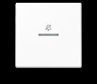
Screwless terminals for wires up to 2.5 mm2 screw fixing only, without claws
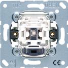
The room unit is used for switching the LEDs of the corridor unit.
* Neutral conductor required

Hotel rocker, room unit for hotel switch insert, room unit, ref.-no.: 506 KO5 EU D 24, 506 KO5 EU D 230 with lens and symbol "Do not disturb"
for A range
Duroplastic (scratch-proof) glossy
Ref.-no.
Hotel push-button insert, corridor unit for hotel rocker corridor unit ref.-no.: .. CU KO5 D .. with red LED lamp
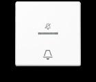
Screwless terminals for wires up to 2.5 mm2 screw fixing only, without claws
The corridor unit indicates the switch position of the room unit.
The push-button is used to activate the bell (e.g. triple-tone door signal, ref.-no. ..567-G3 ..)

DC 24 V
1-pole, 1-way (NO contact) with separate contacts for indicator light 534 KO5 EU D 24
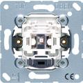

AC 230 V ~
1-pole, 1-way (NO contact) with separate contacts for indicator light * 534 KO5 EU D 230
* Neutral conductor required
Hotel rocker, corridor unit for hotel push-button insert, corridor unit, ref.-no.: 534 KO5 EU D 24, 534 KO5 EU D 230 with lens and symbol "Do not disturb" with symbol "bell"
for A range
Duroplastic
glossy
Duroplastic
Ref.-no.
Hotel switch insert, room unit for hotel rocker room unit ref.-no.: .. RU KO5 M .. with red and green LED lamp
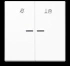

Mechanical interlocking to avoid switching of both rockers at the same time
Screwless terminals for wires up to 2.5 mm2 screw fixing only, without claws
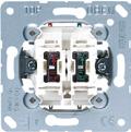
The room unit is used for switching the LEDs of the corridor unit.
DC 24 V
2 x 1-pole, 1-way
2 x 1-pole, 1-way *
* Neutral conductor required

Hotel rocker, room unit for hotel switch insert, room unit, ref.-no.: 505 KO5 VEU M 24, 505 KO5 VEU M 230 with lens and symbols "Do not disturb" and "Make up room"
for A range
Duroplastic (scratch-proof) glossy
for LS range
Duroplastic (scratch-proof) glossy
Ref.-no.
Hotel push-button insert, corridor unit for hotel rocker corridor unit ref.-no.: .. CU KO5 M .. with red and green LED lamp
Screwless terminals for wires up to 2.5 mm2 screw fixing only, without claws
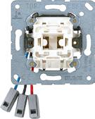
The corridor unit indicates the switch position of the room unit. The push-button is used to activate the bell (e.g. triple-tone door signal, ref.-no. ..567-G3 ..)


* Neutral conductor required

Hotel rocker, corridor unit for hotel push-button insert, corridor unit, ref.-no.: 531 KO5 EU M 24, 531 KO5 EU M 230 with lens and symbols "Do not disturb" and "Make up room" with symbol "bell"
for A range
Duroplastic
Ref.-no. for A range

Hotel centre plate with LED unit 24 V, corridor unit with supporting frame, screw fixing only with red and green LED lamp with lens and symbols "Do not disturb" and "Make up room" The corridor unit indicates the switch position of the room unit.


Thermoplastic (breakproof) high-gloss
(breakproof) lacquered
for LS range
Thermoplastic (breakproof) high-gloss
lacquered)
lacquered)
Hotel centre plate with LED unit 230 V, corridor unit with supporting frame, screw fixing only with red and green LED lamp with lens and symbols "Do not disturb" and "Make up room" The corridor unit indicates the switch position of the room unit.
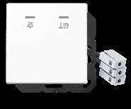

for A range
Thermoplastic (breakproof) high-gloss
Thermoplastic

lacquered
for LS range
Thermoplastic (breakproof) high-gloss
Ref.-no.
Hotel push-button insert, corridor unit for hotel rocker (glass) corridor unit ref.-no.: .. CU KO6 M .. with red and green LED lamp
Screwless terminals for wires up to 2.5 mm2 screw fixing only, without claws

The corridor unit indicates the switch position of the room unit. The push-button is used to activate the bell (e.g. triple-tone door signal, ref.-no. ..567-G3 ..) DC 24 V

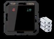
1-pole, 1-way (NO contact)

Hotel rocker (glass), corridor unit for hotel push-button insert, corridor unit, ref.-no.: 531 KO6 EU M 24 with symbol "Do not disturb" (red backlight) and symbol "Make up room" (green backlight) Symbols will be hidden when switched off (fade effect) with printed symbol "bell"
for AS and A ranges
for LS range
Hotel centre plate (glass) with LED unit 24 V, corridor unit with supporting frame, screw fixing only with red and green LED lamp with symbol "Do not disturb" (red backlight) and symbol "Make up room" (green backlight) Symbols will be hidden when switched off (fade effect) The corridor unit indicates the switch position of the room unit.
for AS and A ranges
for LS range
LED pilot light for glass cover ref.-no.: .. CU KO6 TX ..

Intended use
• LED pilot light for use in dry indoor areas
• Installation in flush box according to EN 60670-1
Product characteristics
• Customised labelling, symbols or text in combination with glass cover
• Backlight in white, red, green or orange
Ref.-no.
LED KO6 TX 24
• Color change via separate switch, e.g. ref.-no.: 505 U or 505 KO5 VEU M 24 (not included)
Technical data
Rated voltage: DC 24 V SELV
Rated capacity: < 1.5 W
Ambient temperature: −5 ... +45 °C
Glass cover for LED pilot light ref.-no.: LED KO6 TX 24
The cover is lacquered on the back and can be lasered individually using the Graphic Tool. Order only via Graphic Tool: www.jung.de/gt
for AS and A ranges white
for LS range
Glass cover 2-gang for 2 LED pilot lights ref.-no.: LED KO6 TX 24
The cover is lacquered on the back and can be lasered individually using the Graphic Tool. Order only via Graphic Tool: www.jung.de/gt

Ref.-no.
Triple-tone door signal with supporting frame, screw fixing only 2 separate terminals for 2 or 3 tone signal power supply: 8 ... 12 V AC or 8 ... 24 V DC, via external power supply (SELV) e.g. ref.-no. NT 2405 VDC or NT 2415 REG VDC current consumption: approx. 150 mA
for AS and A ranges
Thermoplastic (breakproof) high-gloss
Thermoplastic (breakproof) lacquered
for CD range
Thermoplastic (breakproof) high-gloss
567-G3 WW
for LS range
Thermoplastic (breakproof) high-gloss
ivory
2567-G3 white
matt lacquered
snow white
2567-G3 WW

2567-G3 WWM
2567-G3 SWM metal versions
matt graphite black
aluminium
2567-G3
stainless steel ES 2567-G3
anthracite (aluminium lacquered) AL 2567-G3 AN
Flush-mounted power supply

Technical data
Input voltage: AC 230 V ~, 50/60 Hz

Input current: 150 mA
Output voltage: DC 24 V
Output current: 500 mA
Dimensions (Ø x H): 54 x 32 mm
Connection: screw terminals
NT 2405 VDC
Power supply for rail mounting
Rail mounting device, 4 rail units
Technical data

Input voltage: AC 100 ... 240 V ~, 50/60 Hz
Input current: 730 mA
Output voltage: DC 24 V SELV
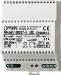
Output current: 1.5 A
Mounting width: 72 mm (4 rail units)
Connection: screw terminals
Hinged lid with symbol "charger" for USB charger ref.-no.: USB 15 CA WW, USB 15 CA SW including centre plate
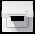
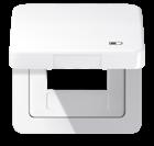
for CD range
Thermoplastic (breakproof) high-gloss
ivory
white
brown
grey
light grey
black
metal versions (anodized aluminium)
gold-bronze
platinum
for LS range with spring
Thermoplastic (breakproof) high-gloss
ivory
white
light grey
Ref.-no.
NT 2415 REG VDC
CD 590 KL USB
CD 590 KL USB WW
CD 590 KL USB BR
CD 590 KL USB GR
CD 590 KL USB LG
CD 590 KL USB SW
CD 590 KL USB GB
CD 590 KL USB PT
LS 990 BFKL USB
LS 990 BFKL USB WW
LS 990 BFKL USB LG
LS 990 BFKL USB SW metal versions
black
aluminium
stainless steel
anthracite (aluminium lacquered)
dark (aluminium lacquered)
classic brass
antique brass
AL 2990 KL USB
ES 2990 KL USB
AL 2990 KL USB AN
AL 2990 KL USB D
ME 2990 KL USB C
ME 2990 KL USB AT
Ref.-no. for CD range

Hinged lid with symbol "plug" for sockets with 50 x 50 mm cover

Thermoplastic (breakproof) high-gloss
ivory
CD 590 KL SOC
white CD 590 KL SOC WW
brown
grey
light grey
CD 590 KL SOC BR
CD 590 KL SOC GR
CD 590 KL SOC LG
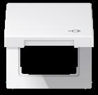
black CD 590 KL SOC SW
metal versions (anodized aluminium)
gold-bronze
platinum
for LS range with spring
Thermoplastic (breakproof) high-gloss
ivory
white
light grey
black
metal versions
aluminium
stainless steel
anthracite (aluminium lacquered)
dark (aluminium lacquered)
classic brass
antique brass
CD 590 KL SOC GB
CD 590 KL SOC PT
LS 990 BFKL SOC
LS 990 BFKL SOC WW
LS 990 BFKL SOC LG
LS 990 BFKL SOC SW
AL 2990 KL SOC
ES 2990 KL SOC
AL 2990 KL SOC AN
AL 2990 KL SOC D
ME 2990 KL SOC C
ME 2990 KL SOC AT
Hinged lid
with symbol "LAN"

for 2-gang modular jack sockets
IAE/UAE sockets ref.-no.: UAE 2 x 8 UPO, UAE 8-8 UPO for sockets Cat. 6 ref.-no.: UAE 8-8 UPOK6 (2 x 8-pol.)

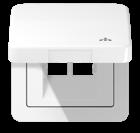
including centre plate
for CD range
Thermoplastic (breakproof) high-gloss
ivory
white
brown
grey
light grey
black
metal versions (anodized aluminium)
gold-bronze
platinum
for LS range
with spring
Thermoplastic (breakproof) high-gloss
ivory
white
light grey
black
metal versions
aluminium
stainless steel
anthracite (aluminium lacquered)
dark (aluminium lacquered)
classic brass
antique brass
Ref.-no.
CD 590 KL LAN
CD 590 KL LAN WW
CD 590 KL LAN BR
CD 590 KL LAN GR
CD 590 KL LAN LG
CD 590 KL LAN SW
CD 590 KL LAN GB
CD 590 KL LAN PT
LS 990 BFKL LAN
LS 990 BFKL LAN WW
LS 990 BFKL LAN LG
LS 990 BFKL LAN SW
AL 2990 KL LAN
ES 2990 KL LAN
AL 2990 KL LAN AN
AL 2990 KL LAN D
ME 2990 KL LAN C
ME 2990 KL LAN AT
Ref.-no.
Electric shaver socket outlet with enhanced contact protection (shutter) Screw terminals for wires up to 4 mm2

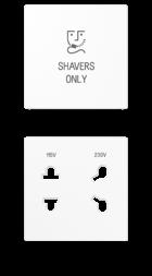
Isolating transformer
Overtemperature protection

Suitable for US NEMA 1 plug (2 pins) and Europlug. Suitable wall boxes: ref.-no. 9062-02, 1656-21
Technical data
Input voltage: AC 230 V ~
Output voltage: AC 115 V ~ and AC 230 V ~
Power: 20 VA
Centre plate for electric shaver socket outlet ref.-no.: SO 7522 EINS The device can be installed into multiple frames of the AS / A ranges.
for AS and A ranges
Duroplastic (scratch-proof) glossy
Duroplastic lacquered
Thermoplastic (breakproof) high-gloss
SO
for LS range
Duroplastic (scratch-proof) glossy
(aluminium lacquered)
(aluminium lacquered)
Wall box for hollow walls, 2-gang for electric shaver socket outlet ref.-no.: SO 7522 EINS
depth: 47 mm 9062-02
cutting hole Ø: 2 x 68 mm
centre distance: 71 mm for panel thickness: 7 – 40 mm

device screws: 4
cable entries 3 x 1.5 mm2: 6
Wall box, 2-gang for electric shaver socket outlet ref.-no.: SO 7522 EINS
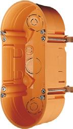
depth: 68 mm 1656-21
length: 149 mm
width: 80 mm
installation opening Ø: 2 x 60 mm
device screws: 4
Temperature controller fan coil, 2-pipe
Intended use
• Switching and operating electrical fan coil units with electrothermically actuated heating/cooling valves
• Measurement and feedback control of the room temperature
• Installation in flush box according to EN 60670-1 (recommendation: deep box)
Product characteristics
• Connection of one fan coil unit with up to 3 fan speeds
• Heating or cooling mode
• Real glass front panel
• 8 capacitive sensor buttons
• Internal temperature sensor
• Room temperature controller function
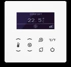
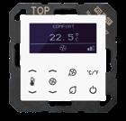
• Preselection of the current energy level through the option of 5 temperature profiles for use in hotels or similar sites
• Display for indication of actual temperature (°C or °F), fan speed, operating mode/profile

• Menu levels blockable
• 1 status LED (red/green/blue)
• Display brightness and contrast adjustable
• Duration of the display illumination up to 120 seconds
• Satellite input for connection of key card holder
Technical data
Rated voltage: AC 110 ... 230 V ~ Mains frequency: 50/60 Hz
Switching output
Contact type: µ
Output current: max. 3 A
Switching capacity
Motors (230 V): 690 VA
Motors (110 V): 300 VA
Outputs for valve drives
Contact type: semiconductor (triac), ε
Switching current: max. 250 mA
Storing temperature: −5 ... +45 °C
Transport temperature: −25 ... +70 °C
Ambient temperature: −5 ... +45 °C
Relative humidity: 5 ... 95 % (no condensation)
Connection mode: screw terminals
single wire: 1.5 mm2
stranded with ferrule: 1.5 mm2
for AS and A ranges
white TRD A 523028 WW
black TRD A 523028 SW
for LS range
white TRD LS 923028 WW
black TRD LS 923028 SW
Ref.-no.
Power supply for temperature controller fan coil (2-pipe) ref.-no.: TRD ..23028 .. (Spare part)
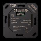
Technical data
Rated voltage: AC 110 ... 230 V ~
Mains frequency: 50/60 Hz
Switching output
Contact type: µ
Output current: max. 3 A
Switching capacity
Motors (230 V): 690 VA
Motors (110 V): 300 VA
Outputs for valve drives
Contact type: semiconductor (triac), ε
Switching current: max. 250 mA
Storing temperature: −5 ... +45 °C
Transport temperature: −25 ... +70 °C
Ambient temperature: −5 ... +45 °C
Relative humidity: 5 ... 95 % (no condensation)

Connection mode: screw terminals
single wire: 1.5 mm2
stranded with ferrule: 1.5 mm2
TRD-NT 2302
Temperature controller fan coil, 4-pipe
Intended use
• Switching and operating electrical fan coil units with electrothermically actuated heating/cooling valves
• Measurement and feedback control of the room temperature
• Installation in flush box according to EN 60670-1 (recommendation: deep box)
Product characteristics
• Connection of one fan coil unit with up to 3 fan speeds
• Heating and/or cooling mode
• Real glass front panel
• 8 capacitive sensor buttons
• Internal temperature sensor
• Room temperature controller function

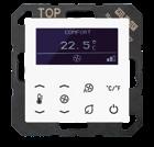
• Preselection of the current energy level through the option of 5 temperature profiles for use in hotels or similar sites
• Display for indication of actual temperature (°C or °F), fan speed, operating mode/profile

• Menu levels blockable
• 1 status LED (red/green/blue)
• Display brightness and contrast adjustable
• Duration of the display illumination up to 120 seconds
• Satellite input for connection of key card holder
Technical data
Rated voltage: AC 110 ... 230 V ~
Mains frequency: 50/60 Hz
Switching output
Contact type: µ
Output current: max. 3 A
Switching capacity
Motors (230 V): 690 VA
Motors (110 V): 300 VA
Outputs for valve drives
Contact type: semiconductor (triac), ε
Switching current: max. 250 mA
Storing temperature: −5 ... +45 °C
Transport temperature: −25 ... +70 °C
Ambient temperature: −5 ... +45 °C
Relative humidity: 5 ... 95 % (no condensation)
Connection mode: screw terminals single wire: 1.5 mm2 stranded with ferrule: 1.5 mm2
for AS and A ranges
white TRD A 523048 WW
black TRD A 523048 SW
for LS range
white TRD LS 923048 WW
black TRD LS 923048 SW
Ref.-no.
Power supply for temperature controller fan coil (4-pipe) ref.-no.: TRD ..23048 .. (Spare part)
Technical data
Rated voltage: AC 110 ... 230 V ~
Mains frequency: 50/60 Hz
Switching output
Contact type: µ

Output current: max. 3 A
Switching capacity
Motors (230 V): 690 VA
Motors (110 V): 300 VA
Outputs for valve drives
Contact type: semiconductor (triac), ε
Switching current: max. 250 mA
Storing temperature: −5 ... +45 °C
Transport temperature: −25 ... +70 °C
Ambient temperature: −5 ... +45 °C
Relative humidity: 5 ... 95 % (no condensation)

Connection mode: screw terminals
single wire: 1.5 mm2
stranded with ferrule: 1.5 mm2
Display for temperature controller fan coil ref.-no.: TRD ..230.. (Spare part)
TRD-NT 2304
These devices are part of the KNX system. Further components of the KNX system can be found from page 658 onward.
KNX temperature controller fan coil
Intended use
• Sensor module for operating electrical fan coil units in KNX installations
• Measurement and feedback control of the room temperature
• Installation in flush box according to EN 60670-1
Product characteristics
• Real glass front panel
• 8 capacitive sensor buttons
• Internal temperature sensor
• External temperature sensor can be evaluated
• Control of fan coil units
• Heating and/or cooling mode
• Suitable for 2-pipe or 4-pipe systems
• Up to 3 fan speeds can be controlled
• Room temperature controller function
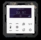
Ref.-no.
• Preselection of the current energy level either through the option of 4 operating modes in accordance with KNX standard or of 5 temperature profiles for use in hotels or similar sites

• Display for indication of actual temperature (°C or °F), fan speed, operating mode/profile
• 1 operating level and 2 menu levels
• Menu levels blockable
• 1 status LED (red/green/blue)
• Display brightness and contrast adjustable
• Duration of the display illumination up to 120 seconds
• Operation as extension unit for temperature controller possible
• Integrated bus coupling unit
Technical data
KNX medium: TP 256
Rated voltage KNX: DC 21 ... 32 V SELV
Current consumption KNX: 8 ... 17.5 mA
Protection class: III
Ambient temperature: −5 ... +45 °C
Storage/transport temperature: −20 ... +70 °C
for AS and A ranges
white TRD A 5248 WW
black TRD A 5248 SW for LS range
white TRD LS 9248 WW black TRD LS 9248 SW

Full version
Ref.-no.
JVP-HOTEL
Note: The software can only be downloaded from the JUNG website https://www.jung.de/en/1508/service/get-your-software-licence/. When downloading, you can choose between the English and the German version. Each installation will run in demo mode for 20 days or 400 starts. For an unrestricted use the software must be activated via a MyJUNG account.
Intended use
• Visualisation and operation of KNX systems via devices with HTML5 browser or app (iOS, Android), e.g. Smart Control (ref.-no.: SC 5 SW, SC 0081 U), smartphone, tablet, laptop, PC, etc.

• Support of KNX IP Secure and KNX Data Secure (as of version 4.5)
• Connection to KNX bus via interfaces (ref.-no. IPR 300 SREG, IPS 300 SREG, 20320 1S IPS R, 2131 USBS REG, 2131 USBS), not included
Product characteristics
• Access from max. 20 different clients possible (with Windows 10)
• Integration of Amazon Alexa voice control via MyJUNG account
• Integration of Google Home voice control via MyJUNG account
• Secure remote access via MyJUNG account
• Update and upgrade compatible
Process connections
• KNX editor/ KNX editor 2.0
• instalight editor
• Device editor
• vitaLED editor
• XPL editor
• SENEC energy storage
• Process model
• Visualisation editor
• Work sheet generator
• Calendar
• JUNG Visu Pro Starter
The JUNG Visu Pro Hotel Software has interfaces to the property management systems Protel and Micros Fidelio (Oracle Hospitality). There is also an interface to Visionline available, the modern hotel locking system from Assa Abloy. In this way, hotel and control software are linked intelligently. The JUNG software enables you to connect up to 150 rooms with functions and processes such as check-in/check-out etc. with only one licence. Licences can be operated in parallel for larger systems. Linking these processes supports an efficient workflow. For example, it is possible via an app for Housekeeping to see which room has already been cleaned. Completed room cleaning can be documented by Housekeeping in real time and shared with colleagues.
Technical requirements
Hardware
• As for Visu Pro Server (ref.-no.: JVP-SERVER-H2) or better
Please note: The performance of the hardware is one of the limiting factors for the project size.
Operating systems
• Windows 10
KNX editor
The Falcon driver of the KNX Association is used for the KNX bus. The KNX connection requires a suitable version of the Falcon driver and the respective interfaces.
Data import from ETS
• ETS5: use of project export of ETS
• ETS4: use of project export of ETS
• ETS3: use of OPC export of ETS
• ETS2 version 1.1, 1.2 and 1.3: files generated by "print export" can be read
• Previous ETS versions: not possible
Special function HOTEL
Extension of the KNX editor to max. 150 KNX tunnel connections
Communication via KNX IP Secure Tunnelling
Integration of third-party systems:
• Door locking systems of Assa Abloy
– Guest card identification
– Staff card identification
– Access counter / documentation
– Evaluation of the door locking system
• Hotel booking software Protel PMS
– Guest identification per room
– Receive requests from the hotel room (e.g. Do not disturb, Make up room etc.)
– Change the room temperature of the PMS system
• Oracle Hospitality OPERA or Oracle Hospitality Suite 8 PMS
– Guest ientification per room
– Receive requests from the hotel room (e.g. Do not disturb, Make up room etc.)
– Change the room temperature of the PMS system

SCHUKO® socket 16 A / 250 V ~
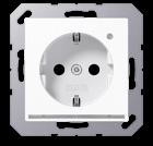
with LED floor pilot light
with integrated brightness sensor
with enhanced contact protection (shutter)
Screwless terminals for wires up to 2.5 mm2
Installation into flush box min. 63 mm (depth)
with white LEDs (colour temperature 4000 K)
Power consumption stand-by / ON: 0.3 / 0.5 W
Supporting frame, claws and claw screws are integrated into the earth protection.
Thermoplastic (breakproof) high-gloss
ivory
white
black
Thermoplastic (breakproof) lacquered
aluminium
mocha
matt lacquered
matt
LED floor pilot light
with integrated brightness sensor
Screwless terminals for wires up to 2.5 mm2
Installation into flush box min. 63 mm (depth) with white LEDs (colour temperature 4000 K)
Power consumption stand-by / ON: 0.3 / 0.5 W

Supporting frame, claws and claw screws are integrated into the earth protection.
Thermoplastic (breakproof) high-gloss
ivory
Thermoplastic (breakproof)
LED floor pilot light
Screwless terminals for wires up to 2.5 mm2
Installation into flush box min. 63 mm (depth) with white LEDs (colour temperature 4000 K)
Power consumption (ON): 0.5 W
The floor pilot light can be switched via an external switch.
Supporting frame, claws and claw screws are integrated into the earth protection.
Thermoplastic (breakproof) high-gloss
Thermoplastic (breakproof) lacquered
lacquered
SCHUKO® socket 16 A / 250 V ~ with LED floor pilot light with integrated brightness sensor with enhanced contact protection (shutter)
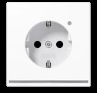
Screwless terminals for wires up to 2.5 mm2 Installation into flush box min. 63 mm (depth) with white LEDs (colour temperature 4000 K)
Power consumption stand-by / ON: 0.3 / 0.5 W

Supporting frame, claws and claw screws are integrated into the earth protection.
Thermoplastic (breakproof) high-gloss ivory
matt lacquered matt snow white
matt graphite black
metal colours (thermoplastic lacquered)
aluminium (lacquered)
stainless steel (lacquered)
anthracite (lacquered)
dark (lacquered)
classic brass (lacquered)
antique brass (lacquered)
LED floor pilot light
with integrated brightness sensor
Screwless terminals for wires up to 2.5 mm2
Installation into flush box min. 63 mm (depth)
with white LEDs (colour temperature 4000 K)
Power consumption stand-by / ON: 0.3 / 0.5 W
Supporting frame, claws and claw screws are integrated into the earth protection.
Thermoplastic (breakproof) high-gloss
ivory
white
light grey
black
matt lacquered
matt snow white
matt graphite black
metal colours (thermoplastic lacquered)
aluminium (lacquered)
stainless steel (lacquered)
anthracite (lacquered)
dark (lacquered)
classic brass (lacquered)
antique brass (lacquered)
LED floor pilot light
Screwless terminals for wires up to 2.5 mm2
Installation into flush box min. 63 mm (depth)
with white LEDs (colour temperature 4000 K)
Power consumption (ON): 0.5 W
The floor pilot light can be switched via an external switch.
Supporting frame, claws and claw screws are integrated into the earth protection.
Thermoplastic (breakproof) high-gloss
ivory
white

light grey
black
matt lacquered
matt snow white
matt graphite black
metal colours (thermoplastic lacquered)
aluminium (lacquered)
stainless steel (lacquered)
anthracite (lacquered)
dark (lacquered)
classic brass (lacquered)
antique brass (lacquered)
Ref.-no.
LS 1539-O LNW
LS 1539-O WW LNW
LS 1539-O LG LNW
LS 1539-O SW LNW
LS 1539-O WWM LNW
LS 1539-O SWM LNW
AL 1539-O LNW
ES 1539-O LNW
AL 1539-O AN LNW
AL 1539-O D LNW
ME 1539-O C LNW
ME 1539-O AT LNW
LS 1539-OO LNW
LS 1539-OO WW LNW
LS 1539-OO LG LNW
LS 1539-OO SW LNW
LS 1539-OO WWM LNW
LS 1539-OO SWM LNW
AL 1539-OO LNW

ES 1539-OO LNW
AL 1539-OO AN LNW
AL 1539-OO D LNW
ME 1539-OO C LNW
ME 1539-OO AT LNW
Ref.-no.
Power supply insert
screw fixing only, without claws
The LED power supply insert is exclusively used for LED pilot light and LED info signs (ref.-no. ..539..). The device is not dimmable.
AC 230/240 V ~, 50 Hz
Technical data
Rated voltage: AC 230/240 V ~, 50 Hz
Ambient temperature: 0 ... +40 °C
Terminals: L, N, L'
Protection class (with mounted cover): II
Power consumption (with mounted cover): typ. 2 x 5.4 VA / 2 x 1.0 W
Connection: screw terminals
Terminals for: 2 x 2.5 mm2 or 1 x 4 mm2
Power supply insert
screw fixing only, without claws
SV 539 LED
The LED power supply insert is exclusively used for LED pilot light and LED info signs (ref.-no. ..539..). The device is not dimmable.
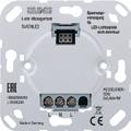
AC 9 ... 36 V ~, 50 Hz; DC 12 ... 48 V
Technical data
Rated voltage
AC-mode operation: AC 9 ... 36 V ~, 50 Hz
DC operation: DC 12 ... 48 V
Ambient temperature: 0 ... +40 °C
Terminals: F1, ⊥, F2
Protection class (with mounted cover): II
Power consumption (with mounted cover)
AC-mode operation: 2 x 1.5 VA
DC operation: 2 x 1.0 W
Connection: screw terminals
Terminals for: 2 x 2.5 mm2 or 1 x 4 mm2
LED info sign with neutral inscription field.
Dimensions: Info sign 71 x 71 mm (complete device 71 x 142 mm).
SV 539-948 LED
Operation only with power supply ref.-no. SV 539 LED or SV 539-948 LED. For complete installation a frame of the respective design range (LS/AL/ES) is required. with white LEDs
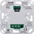
white (aluminium lacquered)
light grey (aluminium lacquered)
black (aluminium lacquered)
metal versions
aluminium
stainless steel (aluminium lacquered)
anthracite (aluminium lacquered)
LED info sign with neutral inscription field.
Dimensions: Info sign 71 x 71 mm (complete device 71 x 142 mm).
Operation only with power supply ref.-no. SV 539 LED or SV 539-948 LED.
LS 539 N71WWLED W
LS 539 N71LGLED W
LS 539 N71SWLED W
AL 2539 N71LED W
ES 2539 N71LED W
AL 2539 N71AN LED W
For complete installation a frame of the respective design range (LS/AL/ES) is required. with blue LEDs


white (aluminium lacquered)
light grey (aluminium lacquered)
black (aluminium lacquered)
metal versions
aluminium
stainless steel (aluminium lacquered)
anthracite (aluminium lacquered)
LS 539 N71WWLED B
LS 539 N71LGLED B
LS 539 N71SWLED B
AL 2539 N71LED B
ES 2539 N71LED B
AL 2539 N71AN LED B
Ref.-no.
LED info sign
with neutral inscription field.
Dimensions: Info sign 71 x 71 mm (complete device 71 x 142 mm).


Operation only with power supply ref.-no. SV 539 LED or SV 539-948 LED. For complete installation a frame of the respective design range (LS/AL/ES) is required. with RGB LEDs
white (aluminium lacquered)
light grey (aluminium lacquered)
black (aluminium lacquered)
metal versions
aluminium
stainless steel (aluminium lacquered)
anthracite (aluminium lacquered)
LS 539 N71WW RGB
LS 539 N71LG RGB
LS 539 N71SW RGB
AL 2539 N71 RGB
ES 2539 N71 RGB
AL 2539 N71AN RGB
The following colours can be selected with the 3-pole DIP switch on the reverse side of the device: red, blue, green, purple, yellow, light blue, white
For individual inscriptions on LED info signs please visit our website www.jung.de/en > Service > LED Info signs
Inscription
LED red/green pilot light
Operation only with power supply ref.-no. SV 539 LED or SV 539-948 LED.
Device with two light pads.
Connection of L and N for green LEDs, L’ and N for red LEDs.
Inscription is possible with printings on transparent foil.
white (aluminium lacquered)
light grey (aluminium lacquered)
black (aluminium lacquered)
metal versions
aluminium
LS 539-2 WW LED RG
LS 539-2 LG LED RG
LS 539-2 SW LED RG
AL 2539-2 LED RG
stainless steel (aluminium lacquered) ES
anthracite (aluminium lacquered) AL
classic brass
LED pilot light


with white and blue LEDs
Operation only with power supply ref.-no. SV 539 LED or SV 539-948 LED.
Connection of L and N for white LEDs, L’ and N for blue LEDs.
Inscription is possible with printings on transparent foil.
white (aluminium lacquered)
light grey (aluminium lacquered)
black (aluminium lacquered)
metal versions
aluminium
stainless steel (aluminium lacquered)
anthracite (aluminium lacquered)
classic brass (lacquered)
antique brass (lacquered)
LS 539 WW LEDWB
LS 539 LG LEDWB
LS 539 SW LEDWB
AL 2539 LEDWB
ES 2539 LEDWB
AL 2539 AN LEDWB
ME 2539 LEDWB C
ME 2539 LEDWB AT
Ref.-no.
LED pilot light with RGB LEDs
Operation only with power supply ref.-no. SV 539 LED or SV 539-948 LED. Connect L, L’ and N or F1, F2 and ⊥ of the power supply. Inscription is possible with printings on transparent foil.
white (aluminium lacquered)
light grey (aluminium lacquered)
black (aluminium lacquered)
metal versions
aluminium
stainless steel (aluminium lacquered)
anthracite (aluminium lacquered)
dark (aluminium lacquered)
classic brass (lacquered)
antique brass (lacquered)
LS 539 WW RGB
LS 539 LG RGB
LS 539 SW RGB
AL 2539 RGB
ES 2539 RGB
AL 2539 AN RGB
AL 2539 RGB D
ME 2539 RGB C
ME 2539 RGB AT
The following colours can be selected with the 3-pole DIP switch on the reverse side of the device: red, blue, green, purple, yellow, light blue, white
LED reading light with white LEDs
Operation only with power supply ref.-no. SV 539 LED or SV 539-948 LED. Connect L, L’ and N or F1, F2 and ⊥ of the power supply.
white (aluminium lacquered)

light grey (aluminium lacquered)
black (aluminium lacquered)
metal versions
aluminium
stainless steel (aluminium lacquered)
anthracite (aluminium lacquered)
LS 539 WW LED LW-12
LS 539 LG LED LW-12
LS 539 SW LED LW-12
AL 2539 LED LW-12
ES 2539 LED LW-12
AL 2539 AN LED LW-12

LED pilot light for glass cover ref.-no.: .. CU KO6 TX ..

Intended use
• LED pilot light for use in dry indoor areas
• Installation in flush box according to EN 60670-1
Product characteristics
• Customised labelling, symbols or text in combination with glass cover
• Backlight in white, red, green or orange
Ref.-no.
LED KO6 TX 24
• Color change via separate switch, e.g. ref.-no.: 505 U or 505 KO5 VEU M 24 (not included)

Technical data
Rated voltage: DC 24 V SELV
Rated capacity: < 1.5 W
Ambient temperature: −5 ... +45 °C
Glass cover for LED pilot light ref.-no.: LED KO6 TX 24
The cover is lacquered on the back and can be lasered individually using the Graphic Tool. Order only via Graphic Tool: www.jung.de/gt
for AS and A ranges
white
for LS range
Glass cover 2-gang for 2 LED pilot lights ref.-no.: LED KO6 TX 24
The cover is lacquered on the back and can be lasered individually using the Graphic Tool. Order only via Graphic Tool: www.jung.de/gt white
Plug & Light redefines interior lighting and makes light control incredibly easy. For perfectly dimmable LED light in the matching JUNG switch design. With Plug & Light, switch and light design comes from a single source and can therefore be specifically tailored to the interior.
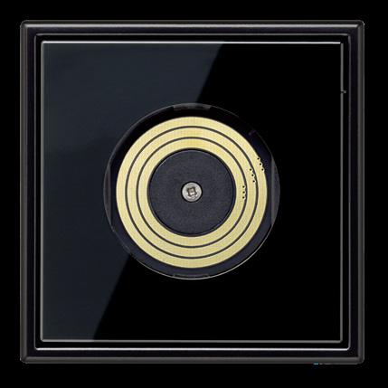 THE LIGHT SOCKET
PLUG & LIGHT LED SPOTLIGHT
Matching with the switch designs, JUNG also offers two LED light attachments in addition to the light socket. The Plug & Light spotlight has a threestage adjustable glare protection and can produce the appropriate lighting effects on ceilings and walls.
PLUG & LIGHT LED WALL LUMINAIRE









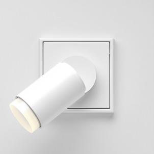

The design of the Plug & Light wall luminaire is reminiscent of a classic switch. With glare-free optics, it sets accent lighting or is used as work light. The light attachments guarantee optimum light distribution over the entire dimming range and can be rotated 360° without any stops.
Dimming like with a classic incandescent lamp.






 WARM DIM
Intended use
• Ballast for switching and dimming light attachments from the Plug & Light system
• Connection to switch, switch inserts with relay contact, electronic switch inserts (trailing edge phase control principle, ref.-no. 1704 ESE), 2-wire LED dimmer (trailing edge phase control principle) and 3-wire LED dimmer (trailing edge phase control principle)
• Compatible dimmers: 1224 LED UDE, 1710 DE, 1711 DE, 1730 DD, 1731 DD, 1724 DM, UD 1755 REG, ULZ 1755 REG, FM UD 420250 REG, FM UD 5500 REG, FM UD 20250 UP, 3901 REGHE, 3902 REGHE, 39004 1S R
• Installation in flush box according to EN 60670-1
Product characteristics
• Automatic detection of the connected light attachments
• Safe extra low voltage SELV DC
Technical data
Rated voltage: AC 230 V ~
Mains frequency: 50/60 Hz
Stand-by power (without light attachment and dimmer): 380 mW
Output voltage: 12 V ± 600 mV
Input current: typical 75 mA
Connected load: max. 8 W
Power factor: typical 0.6
Efficiency: approx. 79 %
Connection: screw terminals
Terminals for: 2.5 mm2
Protection class: II
Ambient temperature: +5 ... +35 °C

Storage/transport temperature: −25 ... +70 °C
The Plug & Light system is designed as a modular system. It consists of a flush-mounted insert with the electronics, a frame, the light socket and a light attachment. JUNG provides compatible frames and covers for Plug & Light. The switch ranges A 550, A CREATION, A FLOW, LS 990, LS DESIGN, LS PLUS and LS ZERO perfectly match the modern LED system.
The light attachment is held in place on the light socket by a strong magnet. Three gold-plated sliding contacts provide the necessary electrical connection. In addition to the power supply, the sliding contacts together with the attachment and light socket regulate the dimming process.

Centre plate for power supply Plug & Light, ref.-no.: PL 08 U
Product characteristics
• Magnetic fixing of light attachments
• Mechanical securing of light attachments for ceiling mounting and as dismounting protection

• Electrical coupling via gold-plated sliding contacts for A range


Thermoplastic (breakproof) high-gloss
white PL A DMS WW
black PL A DMS SW
Thermoplastic (breakproof) lacquered
aluminium PL A DMS AL
for LS range
Thermoplastic (breakproof) high-gloss
white PL LS DMS WW
black PL LS DMS SW
metal colours (thermoplastic lacquered)
aluminium (lacquered)
PL AL DMS-L
stainless steel (lacquered) PL ES DMS-L
Release magnet for dismounting Plug & Light luminaires can also be used to reset WLAN access points ref.-no. WLAN-AC-.. PL MAGNET 01
LED spotlight Plug & Light for power supply Plug & Light, ref.-no.: PL 08 U


white PL S1 D05 WW
– black PL S1 D05 WW SW
PL S1 D05 SW SW
Product characteristics
Rated voltage: DC 12 V SELV
Power consumption: 5.6 W
Connection mode: electrical coupling via gold-plated sliding contacts
Protection class: III
Luminous flux: 390 lm
Colour temperature: 2,700 K

Colour rendering index: typical 85
Beam angle: 35 °
Diameter: 42 mm
Length without anti-glare ring: 80 mm
Length with anti-glare ring: 85 ... 95 mm
Housing material: aluminium lacquered / plastic
Energy efficiency class: A++ to A This luminaire contains built-in LED lamps, which cannot be replaced.
LED spotlight (warm dim) Plug & Light for power supply Plug & Light, ref.-no.: PL 08 U
white PL S1 WD05 WW
white – black PL S1 WD05 WW SW
black PL S1 WD05 SW SW
aluminium – black PL S1 WD05 AL SW
Product characteristics
• Changing the colour temperature between 2700 K and 4000 K with simultaneous brightness increase from minimum to maximum, with suitable LED dimmer • Symmetrical optics, beam angle of 35° • Flicker-free light over the entire dimming range • Light attachment can be changed during ongoing operation • Adjustable anti-glare ring via 3 latch positions (5, 10 and 15 mm) • Swivelling by 90° • Stepless rotation through 360°
Technical data
Rated voltage: DC 12 V SELV
Power consumption: 5.6 W
Connection mode: electrical coupling via gold-plated sliding contacts
Protection class: III
Luminous flux: 350 lm
Colour temperature: 2,700 ... 4,000 K
Colour rendering index: typical 85
Beam angle: 35 °
Diameter: 42 mm
Length without anti-glare ring: 80 mm
Length with anti-glare ring: 85 ... 95 mm
Housing material: aluminium lacquered / plastic
Energy efficiency class: A++ to A
This luminaire contains built-in LED lamps, which cannot be replaced.
Ref.-no.
LED wall luminaire Plug & Light for power supply Plug & Light, ref.-no.: PL 08 U
Thermoplastic (breakproof) high-gloss
white PL F1 D05 WW


black PL F1 D05 SW
metal colours (thermoplastic lacquered)
aluminium (lacquered)
stainless steel (lacquered)
Product characteristics
• Accent lighting or work light
PL F1 D05 AL-L
PL F1 D05 ES-L
• Dimming with suitable LED dimmer at constant colour temperature of 2700 K
• Non-glare asymmetrical optics • Flicker-free light over the entire dimming range • Light attachment can be changed during ongoing operation • Stepless rotation through 360°
Technical data
Rated voltage: DC 12 V SELV
Power consumption: 4.1 W
Connection mode: electrical coupling via gold-plated sliding contacts
Protection class: III
Dimensions (W x H x D): 70 x 70 x 17 mm
Luminous flux: 290 lm
Colour temperature: 2,700 K

Colour rendering index: typical 90
Beam angle: asymmetrical light distribution
Energy efficiency class: A++ to A This luminaire contains built-in LED lamps, which cannot be replaced.
LED wall luminaire (warm dim) Plug & Light for power supply Plug & Light, ref.-no.: PL 08 U
Thermoplastic (breakproof) high-gloss
white
black
metal colours (thermoplastic lacquered)
aluminium (lacquered)
stainless steel (lacquered)
Product characteristics
PL F1 WD05 WW
PL F1 WD05 SW
PL F1 WD05 AL-L
PL F1 WD05 ES-L
• Changing the colour temperature between 2700 K and 4000 K with simultaneous brightness increase from minimum to maximum, with suitable LED dimmer • Non-glare asymmetrical optics • Flicker-free light over the entire dimming range • Light attachment can be changed during ongoing operation • Stepless rotation through 360°
• Accent lighting or work light
Technical data
Rated voltage: DC 12 V SELV
Power consumption: 4.1 W
Connection mode: electrical coupling via gold-plated sliding contacts
Protection class: III
Dimensions (W x H x D): 70 x 70 x 17 mm
Luminous flux: 290 lm
Colour temperature: 2,700 ... 4,000 K
Colour rendering index: typical 90
Beam angle: asymmetrical light distribution
Energy efficiency class: A++ to A
This luminaire contains built-in LED lamps, which cannot be replaced.
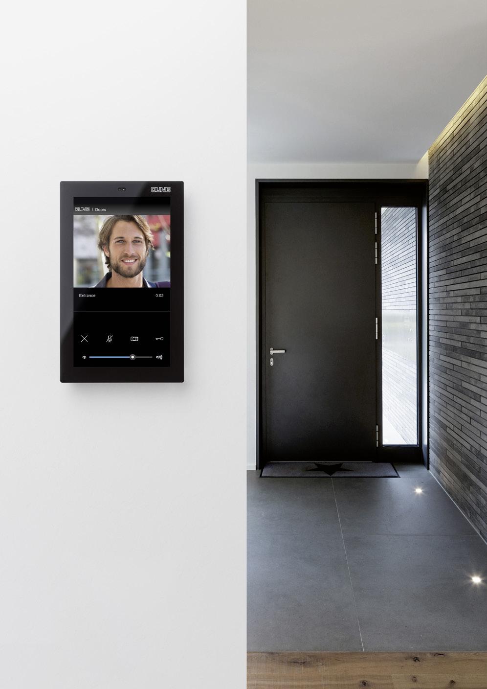
The elegant video and audio indoor stations in the JUNG design are impressive with their variety of design and function. Technically, they are perfectly compatible with Siedle door stations.
Door communication with high standards: the JUNG video and audio indoor stations in switch design are impressive in their functionality and look. Not only do they have a particularly large selection of designs, they are also perfectly compatible with Siedle door


stations thanks to the use of Siedle system technology. The advantages: easy operation and a new variety of possibilities. The JUNG indoor stations fit in harmoniously with the rest of the electrical installation in the overall design.
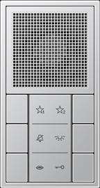 AUDIO INDOOR STATION STANDARD INDOOR STATION
VIDEO INDOOR STATION
LS 990 with chrome frame
LS 990 in aluminium
A CREATION with glass frame
Standard audio indoor station
Product characteristics
• Calling, speech, door release, light, storey call, switching/control functions and internal communication
• 2-wire installation (J-Y(St)Y 2 x 2 x 0.8), protected against polarity reversal
• Speech button with green status LED
• Light and mute buttons are freely configurable. Button functions can be triggered without supplementary installation, e.g. for internal telephony, to initiate switching/control functions in conjunction with Siedle bus switching module BSM/BSE 650-.., selective dialling of door loudspeakers (outdoor stations)
• Using the BPS, a switching function can be configured to the door release button (in conjunction with the Siedle bus switching module BSM/BSE 650-..).
• Integrated audio privacy function
• Parallel switching (simultaneous calling) of max. 4 audio modules or audio indoor stations (from the 3rd device, Siedle BPS is required for programming)
• Speech connection possible at any time, also without a preceding door call
• Connection for Siedle In-Home bus
• Connection for storey call button
• Call generator with 11 ring tone melodies, including chime
• Ring tone volume adjustable in 5 steps up to 83 dB(A)
• Voice volume adjustable in 5 steps
• Programming manual, Plug+Play and using Siedle bus programming software (BPS), in accordance with the Siedle system manual
• Indoor station with handsfree communication
• Status indication during active speech connection
• Call silencing with status indication

• Call differentiation for storey call, 2 door calls and internal call
• Door release / light function at any time via the bus line
• 3 LEDs as indicators (e.g. door open) without additional wiring
• Ready status indicated by an LED
• Optical call indication by flashing LED at the speech button
Ref.-no.
Standard audio indoor station
stand alone device for surface mounting, no frame required
Thermoplastic (breakproof) high-gloss
ivory SI 4 A W
white SI 4 A WW
Thermoplastic (breakproof) lacquered
aluminium SI 4 A AL
• Dimensions (W x H x D): 58 x 129 x 21.5 mm

Conversion kit for standard audio indoor station for installation with 2- to 5-gang frames of the AS and A ranges

SI 46074 AD KIT
Standard audio indoor station Design for AS and A ranges
surface-mounted
The device can be installed into 2- to 5-gang frames.
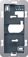
Thermoplastic (breakproof) high-gloss
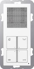
ivory SI 4 AD W
white SI 4 AD WW
Thermoplastic (breakproof) lacquered
aluminium
SI 4 AD AL
Audio indoor station including cover kit and labelling foil without frame
The modules of the indoor station can be installed into multiple frames (horizontally or vertically). Installation in separate frames or surface caps is possible.
Product characteristics
• Calling, speech, door release, light, storey call, switching/control functions and internal communication
• 2-wire installation (J-Y(St)Y 2 x 2 x 0.8), protected against polarity reversal
• Speech button with green status LED
• Light, mute and two function buttons are freely configurable. Button functions can be triggered without supplementary installation, e.g. for internal telephony, to initiate switching/control functions in conjunction with Siedle bus switching module BSM/BSE 650-.., selective dialling of door loudspeakers (outdoor stations)
• Using the BPS, a switching function can be configured to the door release button (in conjunction with the Siedle bus switching module BSM/BSE 650-..).
• Integrated audio privacy function
• Parallel switching (simultaneous calling) of max. 4 audio modules or audio indoor stations (from the 3rd device, Siedle BPS is required for programming)
• Speech connection possible at any time, also without a preceding door call
• High-quality sound and great loudspeaker dynamics
• Elektret condenser microphone
• Connection for Siedle In-Home bus
• Connection for storey call button
• Call generator with 11 ring tone melodies, including chime
• Ring tone volume adjustable in 5 steps up to 92 dB(A)
• Voice volume adjustable in 5 steps
• Programming manual, Plug+Play and using Siedle bus programming software (BPS), in accordance with the Siedle system manual
• Indoor station with handsfree communication
• Status indication during active speech connection
• Call silencing with status indication
• Call differentiation for storey call, 2 door calls and internal call
• Door release / light function at any time via the bus line
• Door call pickup
• Group formation for door calls. Each indoor station can belong to up to 4 groups in the same line
• Intercom functions:
– Call forwarding

– Internal group call
– Automatic call pickup with internal call
– Doormatic
• 5 LEDs as indicators (e.g. door open) without additional wiring
• Ready status indicated by an LED
• Optical call indication by flashing LED at the speech button
• Inscription field
• Labelling foils with symbols for audio and video included
• Audio connection cable (red, 220 mm) included
for CD range
Thermoplastic (breakproof) high-gloss
for LS range
Thermoplastic (breakproof) high-gloss
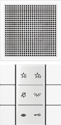
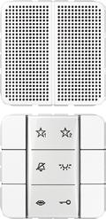
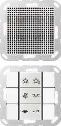

Video indoor stations including cover kit and labelling foil without frame
The modules of the indoor station can be installed into multiple frames (horizontally or vertically). Installation in separate frames or surface caps is possible.
A supplementary supply is required for the operation of the video indoor station. Recommendation: NG 706-30/33-0 from Siedle (see Siedle planning manual).
Product characteristics
• TFT colour monitor
• Screen diagonal 55 mm (2.2'') for A range and 70 mm (2.7'') for CD and LS ranges
• 320 x 240 pixels
• Brightness and colour setting
• Video connection cable (black, 220 mm) included
• Calling, speech, vision, door release, light, storey call, switching/control functions and internal communication
• 2-wire installation, protected against polarity reversal; 2-pole supplementary supply required (J-Y(St)Y 2 x 2 x 0.8)
• Automatic video connection at door call
• Speech button with green status LED
• Light, mute, monitor and function button are freely configurable. Button functions can be triggered without supplementary installation, e.g. for internal telephony, to initiate switching/control functions in conjunction with Siedle bus switching module BSM/BSE 650-.., selective dialling of door loudspeakers (outdoor stations)/cameras
• Using the BPS, a switching function can be configured to the door release button (in conjunction with the Siedle bus switching module BSM/BSE 650-..).
• Integrated audio and video privacy function
• Parallel switching (simultaneous calling) of max. 16 video indoor stations (from the 3rd device, Siedle BPS is required for programming)
• Speech/video connection at any time, also without a preceding door call
• High-quality sound and great loudspeaker dynamics
• Elektret condenser microphone
• Connection for Siedle In-Home bus
• Connection for storey call button
• Call generator with 11 ring tone melodies, including chime
• Ring tone volume adjustable in 5 steps up to 92 dB(A)
• Voice volume adjustable in 5 steps
• Programming manual, Plug+Play and using Siedle bus programming software (BPS), in accordance with the Siedle system manual
• Indoor station with handsfree communication
• Status indication during active speech connection
• Call silencing with status indication
• Call differentiation for storey call, 2 door calls and internal call
• Door release / light function at any time via the bus line
• Door call pickup
• Group formation for door calls. Each indoor station can belong to up to 4 groups in the same line
• Intercom functions:
– Call forwarding

– Internal group call
– Collective announcement
– Automatic call pickup with internal call
– Doormatic
• Connection for supplementary supply (required for operation of a video module, illumination of the inscription field in the universal push-button module, and when connecting a second push-button module)
Video indoor station 2.2’’ for AS and A ranges
Thermoplastic (breakproof) high-gloss
Thermoplastic (breakproof) lacquered


Video indoor station 2.7’’ for CD range
Thermoplastic (breakproof) high-gloss
Video indoor station 2.7’’ for LS range
Thermoplastic (breakproof) high-gloss


Ref.-no.
Single components:
Audio module

Product characteristics
• Can also be used as a secondary signal unit (bell)
• Calling and storey call
• 2-wire installation (J-Y(St)Y 2 x 2 x 0.8), protected against polarity reversal
• Parallel switching (simultaneous calling) of max. 4 audio modules or audio indoor stations (from the 3rd device, Siedle BPS is required for programming)
• High-quality sound and great loudspeaker dynamics
• Elektret condenser microphone
• Connection for Siedle In-Home bus
• Connections for storey call button and to additional modules
• Call generator with 11 ring tone melodies, including chime
• Ring tone volume adjustable in 5 steps up to 92 dB(A)
• Voice volume adjustable in 5 steps
• Programming manual, Plug+Play and using Siedle bus programming software (BPS), in accordance with the Siedle system manual
• Automatic call pickup with internal call

for AS and A ranges
Thermoplastic (breakproof) high-gloss
(breakproof) lacquered
for CD range
Thermoplastic (breakproof) high-gloss
for LS range
Thermoplastic (breakproof) high-gloss
lacquered)
Standard push-button module for audio module and as extension module for a Universal push-button module To be completed with cover kit 3-gang (ref.no.: .. 503 TSA ..)

Product characteristics
• 5 LEDs as indicators (e.g. door open) without additional wiring

• Ready status indicated by an LED
• Optical call indication by flashing LED at the speech button

• Inscription field
• Labelling foils with symbols for audio and video included
• Audio connection cable (red, 220 mm) included
for AS and A ranges
Cover kit 3-gang see page 662
for CD range
Cover kit 3-gang see page 665
for LS range
Cover kit 3-gang see page 668
Ref.-no.
Universal push-button module
Is required for operation of a video module and when connecting a second push-button module (only in combination with supplementary supply, see Siedle planning manual).
To be completed with cover kit 3-gang (ref.no.: .. 503 TSA ..)
Product characteristics
• 5 LEDs as indicators (e.g. door open) without additional wiring
• Ready status indicated by an LED
• Optical call indication by flashing LED at the speech button

• Inscription field can be illuminated
• Labelling foils with symbols for audio and video included
• Audio connection cable (red, 220 mm) included
• Connection for supplementary supply (required for operation of a video module, illumination of the inscription field in the universal push-button module, and when connecting a second push-button module)
• Connection for an additional push-button module (standard or universal, max. 2 push-button modules per indoor station)
for AS and A ranges
Cover kit 3-gang see page 662
for CD range
Cover kit 3-gang see page 665
for LS range
Cover kit 3-gang see page 668
Video module 2.2’’
Product characteristics
• TFT colour monitor
• Screen diagonal 55 mm (2.2’’)
• 320 x 240 pixels
• Brightness and colour setting
• Video connection cable (black, 220 mm) included
• Operation only in combination with universal push-button module and audio module
for AS and A ranges
Video module 2.7’’
Product characteristics
• TFT colour monitor


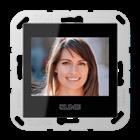
• Screen diagonal 70 mm (2.7’’)
• 320 x 240 pixels

• Brightness and colour setting
• Video connection cable (black, 220 mm) included
• Operation only in combination with universal push-button module and audio module
for CD range
for LS range
Connection cable (Spare part)
for connecting the modules in a multiple frame
Technical data
Cable length: 220 mm
Connection cable
Using the optionally available connection cables, the modules can be positioned up to 500 mm apart from each other.
length: 700 mm

Labelling foil (Spare part)
labelling foils with symbols, one for audio and one for video
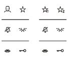


for AS and A ranges
for CD range
for LS range
Symbol cover audio for AS and A ranges with printed symbols to clip on audio indoor station (ref.-no.: SI AI A 6 ..) or push-button modules (ref.-no.: SI TM A 5073, SI TM A 5093)
dimensions: 25 x 55 mm
Thermoplastic (breakproof) high-gloss
Thermoplastic (breakproof) lacquered

Symbol cover video for AS and A ranges with printed symbols to clip on video indoor station (ref.-no.: SI VI A 622 ..) or push-button modules (ref.-no.: SI TM A 5073, SI TM A 5093)
dimensions: 25 x 55 mm
Thermoplastic (breakproof) high-gloss
Thermoplastic (breakproof) lacquered
Symbol cover audio for CD range with printed symbols to clip on audio indoor station (ref.-no.: SI AI CD 6 ..) or push-button modules (ref.-no.: SI TM CD 5073, SI TM CD 5093)
dimensions: 33 x 68 mm
Thermoplastic (breakproof) high-gloss
ivory
Symbol cover video for CD range with printed symbols to clip on video indoor station (ref.-no.: SI VI CD 627 ..) or push-button modules (ref.-no.: SI TM CD 5073, SI TM CD 5093)
dimensions: 33 x 68 mm

Thermoplastic (breakproof) high-gloss
ivory
white
Symbol cover audio for LS range with printed symbols to clip on audio indoor station (ref.-no.: SI AI LS 6 .., SI AI AL 6 .., SI AI ES 6) or push-button modules (ref.-no.: SI TM LS 5073, SI TM LS 5093)
dimensions: 33 x 70.5 mm
Thermoplastic (breakproof) high-gloss ivory
metal colours (thermoplastic lacquered)
aluminium (lacquered)
stainless steel (lacquered)
Symbol cover video for LS range with printed symbols to clip on video indoor station (ref.-no.: SI VI LS 627 .., SI VI AL 627, SI VI ES 627) or push-button modules (ref.-no.: SI TM LS 5073, SI TM LS 5093)

dimensions: 33 x 70.5 mm

Thermoplastic (breakproof) high-gloss
ivory
metal colours (thermoplastic lacquered)
aluminium (lacquered)
stainless steel (lacquered)
other colours on request
Connection block (Spare part)
2-gang
Terminating resistor video (Spare part)
A terminating resistor is connected between the TaM and TbM terminals of the audio module. This terminating resistor is required if the modular indoor station is the last device in a video line. If you loop the bus through the modular indoor station, this terminating resistor must be removed.
Smart Control 8 see page 699
Smart Control 5 for installation in walls, capacitive touch screen fanless, without rotating parts
Intended use
Ref.-no.
• Visualisation and operation of system statuses and information on building automation
• For vertical installation
• Installation in flush box according to EN 60670-1
• Ensure correct orientation when installing the flush box. Mounting screws must be in vertical alignment. Product characteristics
• KNX visualisation in combination with Visu Pro Server (ref.-no.: JVP-SERVER-H2)
• KNX visualisation in combination with Smart Visu Server (ref.-no.: SV-SERVER-INT)
• eNet visualisation in combination with eNet server for rail mounting (ref.-no.: ENET-SERVER) with software version 2.2 or higher
• Door call function only in combination with Siedle Smart Gateway SG 650-.. or SG 150-..
• High performance HD screen
• Proximity sensor
• Graphical user interface
• Brightness level of display adapts automatically to ambient brightness

• Smart Gateway with integrated image storage
Technical data
Rated voltage: DC 24 V SELV


Rated capacity: 12 W
Screen diagonal: 127 mm / 5’’
Resolution: 720 x 1280
Frame dimensions (W x H): 81 x 132 mm
Power supply: PoE acc. to IEEE 802.3af or DC 24 V via external power supply (not included)
Processor: Cortex-A53
Loudspeaker: integrated
Microphone: integrated
LAN connections: 1 x 10/100 Mbit/s
Ambient temperature: 0 ... +30 °C
Power supply for rail mounting for Smart Control ref.-no.: SC 5 SW
Rail mounting device, 4 rail units
Technical data
Input voltage:
AC 100 ... 240 V ~, 50/60 Hz
Input current: 730 mA
Output voltage: DC 24 V SELV
Output current: 1.5 A
Mounting width: 72 mm (4 rail units)
Connection: screw terminals
Flush-mounted power supply for Smart Control ref.-no.: SC 5 SW
Technical data
Input voltage:
AC 230 V ~, 50/60 Hz
Input current: 150 mA
Output voltage: DC 24 V
Output current: 500 mA
Dimensions (Ø x H): 54 x 32 mm
Connection: screw terminals
NT 2415 REG VDC
NT 2405 VDC
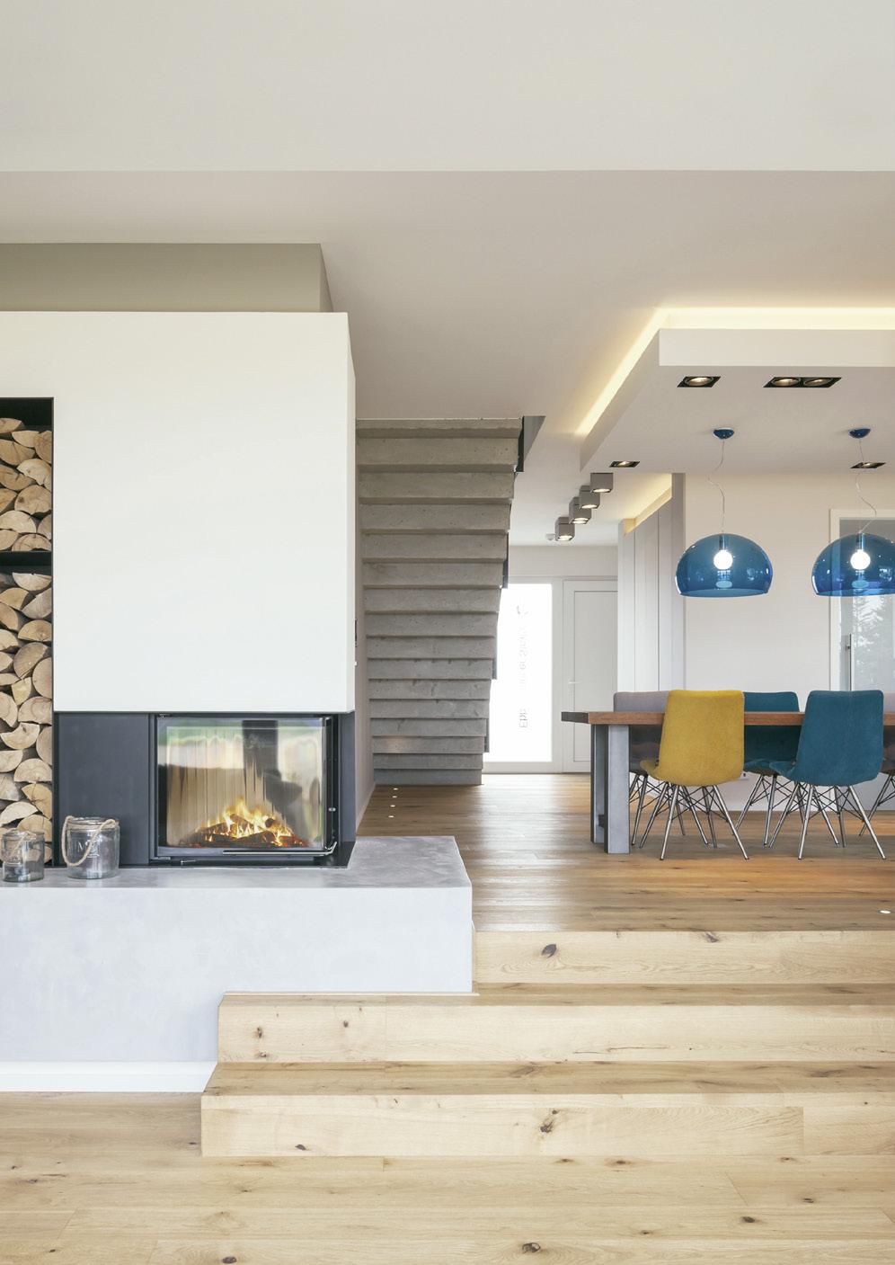

This is the browser-based set-up interface for installers. It links the eNet transmitters to the actuators and makes or defines settings and performs diagnostics.
eNet
The app is available in Android and iOS versions and enables operation of the eNet SMART HOME facility through a smartphone. Simple operation takes place through the home network or through remote access over the internet.
The home under control at all times: users can always access their eNet installation via the eNet SMART HOME app even when on the move. Up to eight end devices can be used with one registration. The information security of the remote access eNet SMART HOME remote (backend API) is verified by VDE.
The remote service is available to the user free of charge for 12 months.
The eNet SMART HOME is protected by targeted security measures. These include data security, the server location in Germany and protection against manipulation as well as pre-encrypted radio transmission. Secure communication
The information security of the remote access eNet SMART HOME remote (backend API) is verified by VDE.

eNet SMART HOME is modern radio technology in a future-proof, networked system. It is operated via wall-mounted transmitters, touch displays, tablet and smartphone or via voice command –fully encrypted and secure, even for remote access.
The browser-based eNet SMART HOME connect set-up interface is already integrated in the eNet Server. This makes it convenient to assign devices, functions and installations on the display. The documentation and processing of created projects are easily done. As soon as the computer and the eNet Server are connected with each other, the application can be started.
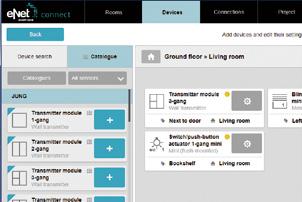
The rooms for a project are created first. These can be freely named. Careful structure planning is important, as this is reflected 1:1 in the visualisation.
The device search is used to add devices from the eNet system to the project. In this way, all devices in learning mode or that have been connected to the electrical supply in the last few minutes are found and displayed. Afterwards, the devices can be allocated to rooms and the device channels named individually as appropriate for their use.
Now, actuator and sensor channels are assigned to each other and functionally connected with each other. The devices networked in this way communicate with each other directly when operated, which results in a very robust, fail-safe function.
In the final step, the project design data are written to the devices. The app visualisation is generated automatically. In addition, the electrical installer can export the project, use it as a backup or as a template for future projects.
Everything under mobile control
Control eNet SMART HOME from anywhere: simply via mobile app – whether in your own WLAN or via remote access. Including all settings affecting the Smart Home. Base: the eNet Server.
Display all rooms with their functions
Simply record and control all functions
Combine functions into comfort scenes
Integrate smart heating control
Create time-controlled function sequences
Fingertip operation of all individual functions
Ref.-no.
eNet radio hand-held transmitter
1-gang Toggle
New system feature: Fully-encrypted radio transmission (AES-CCM) from eNet Server software version 2.0
anthracite
Intended use
• Radio hand transmitter for radio transmission of switching, dimming, and blind movement commands
Product characteristics
• One button for switching and dimming a channel
• Status indication with LED
Can be set with eNet server
• Scenes: All On, All Off, individual scenes
Supplementary functions with eNet server
• Fully-encrypted radio transmission (AES-CCM) from eNet Server software version 2.0
Technical data
Rated voltage: DC 3 V
FM HS 1 T
• Operation with radio actuators from the eNet system
• Battery-powered device
• Signalling of transmission errors can be switched off
• Operating locks
• Update of the device software
• Reading of error memory
Battery type: 1 x lithium CR 2450N (included)
Ambient temperature: −5 ... +45 °C
Dimensions (L x W x H): 55 x 40.5 x 15 mm
Radio frequency: 868.0 ... 868.6 MHz
Transmitting power: max. 20 mW
Transmission range in free field: typical 100 m
Receiver category: 2
eNet radio hand-held transmitter
2-gang
New system feature: Fully-encrypted radio transmission (AES-CCM) from eNet Server software version 2.0
anthracite
Intended use
• Hand transmitter for radio transmission of switching, dimming, blind movement and scene commands
Product characteristics
• Two adjacent buttons each belong to one channel
• Status indication with LED
• Switch-on brightness of dimmer actuators can be saved

Can be set with eNet server
• Scene All On
Supplementary functions with eNet server
• Fully-encrypted radio transmission (AES-CCM) from eNet Server software version 2.0
Technical data
Rated voltage: DC 3 V
• Operation with radio actuators from the eNet system
• Battery-powered device
• Scenes, radio hand transmitter, 2x: All Off, three individual scenes
• Signalling of transmission errors can be switched off
• Operating locks
• Update of the device software
• Reading of error memory
Battery type: 1 x lithium CR 2450N (included)
Ambient temperature: −5 ... +45 °C
Dimensions (L x W x H): 55 x 40.5 x 15 mm
Radio frequency: 868.0 ... 868.6 MHz
Transmitting power: max. 20 mW
Transmission range in free field: typical 100 m
Receiver category: 2
Ref.-no.
eNet radio hand-held transmitter
4-gang
New system feature: Fully-encrypted radio transmission (AES-CCM) from eNet Server software version 2.0
anthracite
Intended use
• Hand transmitter for radio transmission of switching, dimming, blind movement and scene commands
Product characteristics
• Two adjacent buttons each belong to one channel
• Status indication with LED
• Switch-on brightness of dimmer actuators can be saved

Can be set with eNet server
• Scene All On
Supplementary functions with eNet server
• Fully-encrypted radio transmission (AES-CCM) from eNet Server software version 2.0
Technical data
Rated voltage: DC 3 V
FM HS 4
• Operation with radio actuators from the eNet system
• Battery-powered device
• Scenes, radio hand transmitter, 4x: All Off, seven individual scenes
• Signalling of transmission errors can be switched off
• Operating locks
• Update of the device software
• Reading of error memory
Battery type: 1 x lithium CR 2450N (included)
Ambient temperature: −5 ... +45 °C
Dimensions (L x W x H): 93 x 53 x 15.5 mm
Radio frequency: 868.0 ... 868.6 MHz
Transmitting power: max. 20 mW
Transmission range in free field: typical 100 m
Receiver category: 2
Ref.-no.
eNet universal radio transmitter mini 2-gang
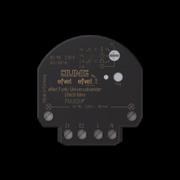
New system feature: Fully-encrypted radio transmission (AES-CCM) from eNet Server software version 2.0

Intended use
• Transmitter for radio communication of switching, dimming, blind movement and scene commands
• Activation by push-button, switch, shutter push-button, shutter switch or other devices with push-button contact or switching contact
• Installation in flush box according to EN 60670-1 in combination with a suitable cover
• Mounting in surface-mounted housing or mounting adapter (ref.-no. FM-EBG) for false ceilings
• Operation with radio actuators from the eNet system
Product characteristics
• Detection of voltage levels and changes on the input • Settable transmission behaviour • Connection for signal lamp – e.g. for connection of push-buttons with separate signal contact (ref.-no. 534 U) • Display of transmission status with status LED or signal lamp
Operating modes, settable with operating mode switch:
• 1-gang switching/dimming/blind • 1-gang automatic function • 2-gang switching/dimming/push-button operation • 2-gang automatic function Can be set with eNet server: • Fully-encrypted radio transmission (AES-CCM) from eNet Server software version 2.0 • Scenes: All On, All Off, individual scenes • 2-gang blind
• Operating locks • Setup connections enabled/disabled • Status for restraint • Repeater function • Update of the device software
Single- and dual-area operation
The operation of functions or electrical loads depends on the application and the connected components. The operation of the usual switching function follows if switches are connected. Two operating modes are used when push-buttons are connected: • Single-area operation – lighting: Switching lighting on or off or dimming it brighter/darker takes place alternately when the appropriate button is pressed repeatedly. • Dual-area operation – lighting: Two buttons form a function pair. Pressing the left button switches or dims lighting on or brighter, pressing the right one switches it off or makes it darker. • Single-area operation – blind: Upward or downward movement takes place alternately when the appropriate button is pressed repeatedly. • Dual-area operation – blind: Two buttons form a function pair. Pressing the left button moves a blind upwards, pressing the right one moves it downwards.
Technical data
Rated voltage: AC 110 ... 230 V ~, 50/60 Hz
Stand-by power: 0.5 W
Ambient temperature: −25 ... +70 °C
Inputs
Cable length: max. 100 m
Input current at rated voltage: approx. 2 mA
Signal duration: min. 200 ms
Signal lamp output
Rated voltage (switching voltage): AC 110 ... 230 V ~
Output current: 40 mA
Connection mode: screw terminals
single wire: 1 x 0.75 ... 4 mm2
stranded with ferrule: 1 x 0.75 ... 2.5 mm2
Dimensions (Ø x H): 53 x 23 mm
Radio frequency: 868.0 ... 868.6 MHz
Transmitting power: max. 20 mW
Transmission range in free field: typical 100 m
Receiver category: 2
Ref.-no.
eNet radio transmitter modules F 50
including mounting plate, adhesive film and fastening screw
New system feature: Fully-encrypted radio transmission (AES-CCM) from eNet Server software version 2.0
Intended use
• Radio sensor for transmission of switching, dimming, blind movement and scene commands
• Operation with radio actuators from the eNet system
• Mounting on flush box according to EN 60670-1, screw fixing on walls or adhesive fixing on smooth, even surfaces (glass)
Product characteristics
• Two adjacent buttons each belong to one channel
• Display of the actuator status for status poll by a green LED per channel
• Display of the transmission status by a red LED
• Switch-on brightness of dimmer actuators can be saved

• Battery-powered device (battery compartment accessible from front)
• Signalling of transmission errors can be switched off
Can be set with eNet server:
• Scene All On
• Operating locks
Supplementary functions with eNet server:
• Fully-encrypted radio transmission (AES-CCM) from eNet Server software version 2.0
• Update of the device software
Technical data
Rated voltage: DC 3 V
Battery type: 1 x lithium CR 2450N (included)
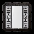
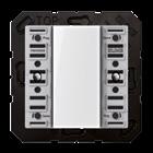
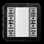
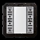
Ambient temperature: −5 ... +45 °C
Radio frequency: 868.0 ... 868.6 MHz
Transmitting power: max. 20 mW
Transmission range in free field: typical 100 m
Receiver category: 2
eNet radio transmitter modules F 50 for AS and A ranges
eNet radio transmitter module 1-gang including transparent cover ref.-no.: A 50 NA for cover kit 1-gang, ref.-no.: A 501 TSA ..
eNet radio transmitter module 2-gang including transparent cover ref.-no.: A 50 NA for cover kit 2-gang, ref.-no.: A 502 TSA ..
eNet radio transmitter module 3-gang including transparent cover ref.-no.: A 50 NA for cover kit 3-gang, ref.-no.: A 503 TSA ..
FM A 5003 M
eNet radio transmitter module 4-gang including transparent cover ref.-no.: A 50 NA for cover kit 4-gang, ref.-no.: A 504 TSA ..
Cover kits see page 662
Ref.-no.
eNet radio transmitter modules F 50 for CD range


eNet radio transmitter module 1-gang including transparent cover ref.-no.: CD 50 NA for cover kit 1-gang, ref.-no.: CD 501 TSA ..
FM CD 5001 M
eNet radio transmitter module 2-gang including transparent cover ref.-no.: CD 50 NA for cover kit 2-gang, ref.-no.: CD 502 TSA ..
FM CD 5002 M
eNet radio transmitter module 3-gang including transparent cover ref.-no.: CD 50 NA for cover kit 3-gang, ref.-no.: CD 503 TSA ..
FM CD 5003 M
eNet radio transmitter module 4-gang including transparent cover ref.-no.: CD 50 NA for cover kit 4-gang, ref.-no.: CD 504 TSA ..
Cover kits see page 665
FM CD 5004 M
eNet radio transmitter modules F 50 for LS range

eNet radio transmitter module 1-gang including transparent cover ref.-no.: LS 50 NA for cover kit 1-gang, ref.-no.: ..501 TSA .. in the LS range Cannot be combined with frames in FLAT DESIGN.
Ref.-no.
eNet radio transmitter module 2-gang including transparent cover ref.-no.: LS 50 NA for cover kit 2-gang, ref.-no.: ..502 TSA .. in the LS range Cannot be combined with frames in FLAT DESIGN.
eNet radio transmitter module 3-gang including transparent cover ref.-no.: LS 50 NA for cover kit 3-gang, ref.-no.: ..503 TSA .. in the LS range Cannot be combined with frames in FLAT DESIGN.
eNet radio transmitter module 4-gang including transparent cover ref.-no.: LS 50 NA for cover kit 4-gang, ref.-no.: ..504 TSA .. in the LS range Cannot be combined with frames in FLAT DESIGN.
Cover kits see page 668
Ref.-no.
eNet radio transmitter modules F 40
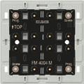


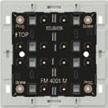
New system feature: Fully-encrypted radio transmission (AES-CCM) from eNet Server software version 2.0 Adapter frames are included in delivery: ref.-no. LS 4 AR for LS range (pre-mounted) and ref.-no. CD 4 AR for CD range. AS / A ranges without adapter frame. including mounting plate, adhesive film and fastening screw Cannot be combined with frames in FLAT DESIGN.
Intended use
• Radio sensor for transmission of switching, dimming, blind movement and scene commands
• Operation with radio actuators from the eNet system
• Mounting on flush box according to EN 60670-1, screw fixing on walls or adhesive fixing on smooth, even surfaces (glass)
Product characteristics
• Each button is "divided" into an upper and lower half belonging to a channel
• Display of the actuator status for status poll by a green LED per channel
• Display of the transmission status by a red LED
• Switch-on brightness of dimmer actuators can be saved
• Battery-powered device
• Signalling of transmission errors can be switched off Can be set with eNet server:

• Scene All On
• Operating locks
Supplementary functions with eNet server:
• Fully-encrypted radio transmission (AES-CCM) from eNet Server software version 2.0
• Update of the device software
Technical data
Rated voltage: DC 3 V
Battery type: 1 x lithium CR 2450N (included)
Ambient temperature: −5 ... +45 °C
Radio frequency: 868.0 ... 868.6 MHz
Transmitting power: max. 20 mW
Transmission range in free field: typical 100 m
Receiver category: 2
eNet radio transmitter module 1-gang for cover kit 1-gang, ref.-no.: .. 401 TSA .. for cover 1-gang with symbols, ref.-no.: .. 401 TSAP ..
eNet radio transmitter module 2-gang for cover kit 2-gang, ref.-no.: .. 402 TSA .. for cover 2-gang with symbols, ref.-no.: .. 402 TSAP ..
eNet radio transmitter module 3-gang for cover kit 3-gang, ref.-no.: .. 403 TSA .. for cover 2-gang with symbols, ref.-no.: .. 402 TSAP .. for cover 4-gang with symbols, ref.-no.: .. 404 TSAP ..
eNet radio transmitter module 4-gang for cover kit 4-gang, ref.-no.: .. 404 TSA .. for cover 4-gang with symbols, ref.-no.: .. 404 TSAP ..
Cover kits see page 671 – 673
FM 4001 M
FM 4002 M
FM 4003 M
FM 4004 M
eNet Standard radio centre plate for LB Management inserts "blinds" ref.-no.: 1730 JE and 1731 JE for LB Management inserts "light" ref.-no.: 1701 SE, 1704 ESE, 1702 SE, 1710 DE, 1711 DE, 1713 DSTE, 1723 NE
Intended use
• Manual, radio-controlled and time-controlled operation of e.g. blinds, shutters, awnings, lighting or fans
• Transmitter for radio communication of switching, dimming and blind commands
• Operation with switch, dimmer or blinds insert or satellite insert 3-wire of the LB Management
Product characteristics
• Status feedback to radio transmitter
• Status indication with LED
• Night mode
• Evaluation of satellite inputs
Functions in combination with blinds insert
• Positioning of the blind/shutter via scene request
• Position for sun protection and twilight
• Running time and ventilation position of the blind/shutter can be saved
Functions in combination with light insert
• Scene operation possible
• Switch-on brightness can be saved permanently when combined with flush-mounted inserts for dimming
Functions in combination with relay switch insert 2-channel
• Output a2 switches depending on output a1 e.g. to switch on ventilation, depending on the lighting, and switch it off with a delay.
• Switch-on delay of output a2 adjustable
• Run-on time of output a2 adjustable
Can be set with eNet server from version 2.2 (depending on insert):
• Repeater function
• Slat change-over time/fabric-stretching time
• Change-over time for direction change
• Running direction invertible
• Operating locks
• Deactivating extension evaluation
• Position for sun protection, twilight, lock-out protection and wind alarm

• Maximum brightness
• Minimum brightness
• Dimming speed
• Switch-on delay / switch-off delay
• Dim up/dim down ramp
• Switch-off warning
• Continuous on, Continuous off
• Hotel function
• Run-on time
• Light control
In order to use the eNet Standard radio centre plate, the eNet Server has to have at least version 2.3.
Supplementary functions with eNet server:
• Fully-encrypted radio transmission (AES-CCM)
• Update of the device software
• Reading of error memory

eNet Standard radio centre plate
for AS range
Duroplastic (scratch-proof) glossy
for A range Duroplastic (scratch-proof) glossy


(breakproof) high-gloss
for CD range
Duroplastic (scratch-proof) glossy
(duroplastic lacquered)
for LS range
Duroplastic (scratch-proof) glossy
eNet Standard radio centre plate "arrows"

for AS range
Duroplastic (scratch-proof) glossy


for A range
Duroplastic (scratch-proof) glossy
Thermoplastic (breakproof) high-gloss
for CD range
Duroplastic (scratch-proof) glossy
(duroplastic lacquered)
for LS range
Duroplastic (scratch-proof) glossy
eNet radio centre plate for LB Management inserts "blinds" ref.-no.: 1730 JE and 1731 JE for LB Management inserts "light" ref.-no.: 1701 SE, 1704 ESE, 1702 SE, 1710 DE, 1711 DE, 1713 DSTE, 1723 NE
Intended use
• Manual, radio-controlled and time-controlled operation of e.g. blinds, shutters, awnings, lighting or fans
• Transmitter for radio communication of switching, dimming and blind commands
• Operation with switch, dimmer or blinds insert or satellite insert 3-wire of the LB Management
Product characteristics
• 2 switching times can be saved, which are repeated in a 24-hour cycle
• Disabling function
• Status feedback to radio transmitter
• Status indication with LED
• Night mode
• Evaluation of satellite inputs
Functions in combination with blinds insert
• Positioning of the blind/shutter via scene request
• Position for sun protection and twilight
• Running time and ventilation position of the blind/shutter can be saved
Functions in combination with light insert
• Scene operation possible
• Switch-on brightness can be saved permanently when combined with flush-mounted inserts for dimming
Functions in combination with relay switch insert 2-channel
• Output a2 switches depending on output a1 e.g. to switch on ventilation, depending on the lighting, and switch it off with a delay.
• Switch-on delay of output a2 adjustable
• Run-on time of output a2 adjustable
Can be set with eNet server from version 2.2 (depending on insert):
• Repeater function
• Slat change-over time/fabric-stretching time
• Change-over time for direction change
• Running direction invertible
• Operating locks
• Deactivating extension evaluation
• Position for sun protection, twilight, lock-out protection and wind alarm

• Maximum brightness
• Minimum brightness
• Dimming speed
• Switch-on delay / switch-off delay
• Dim up/dim down ramp
• Switch-off warning
• Continuous on, Continuous off
• Hotel function
• Run-on time
• Light control
Supplementary functions with eNet server:
• Fully-encrypted radio transmission (AES-CCM)
• Update of the device software
• Reading of error memory
eNet radio centre plate


for AS range

Duroplastic (scratch-proof) glossy
for A range
Duroplastic (scratch-proof) glossy
Duroplastic
Thermoplastic (breakproof) high-gloss


for CD range
Duroplastic (scratch-proof) glossy
metal colours (duroplastic lacquered) gold-bronze
for LS range
Duroplastic (scratch-proof) glossy


eNet radio centre plate "arrows"
for AS range
Duroplastic (scratch-proof) glossy
for A range
Duroplastic (scratch-proof) glossy
Thermoplastic (breakproof) high-gloss
for CD range
Duroplastic (scratch-proof) glossy
colours (duroplastic lacquered)
LS range
Duroplastic (scratch-proof) glossy
lacquered)
(aluminium lacquered)
Ref.-no.
eNet radio brightness detector, solar-powered New system feature: Fully-encrypted radio transmission (AES-CCM) from eNet Server software version 2.0
Intended use
• Sensor for brightness-dependent control of eNet actuators
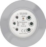
• Mounting on window panes in indoor areas
Product characteristics
• Triggers scenes when the set sun protection and twilight value is exceeded or undershot
• Temperature-dependent sun protection possible

• Scene buttons for sun protection and twilight
• Brightness measurement via brightness sensor
• Sends brightness values to the eNet server if brightness changes more than 50 %
• Test operation for adjusting protection and temperature threshold
• Solar-powered device
• Integrated battery as energy storage
Can be set with eNet server:
• Operating locks
Supplementary functions with eNet server:
• Fully-encrypted radio transmission (AES-CCM) from eNet Server software version 2.0
• Update of the device software
• Reading of error memory
Sun protection
The sun protection function allows automatic lowering of a blind/shutter in strong sunlight. If a set sun protection value is exceeded for more than 2 minutes, the sun protection sensor transmits the "Sun protection" scene and the blinds move to their previously saved sun protection position. If the brightness falls below the set sun protection value for longer than 15 minutes, then the blind/shutter will move upwards again.
Sun protection, temperature-dependent
Temperature-dependent sun protection can primarily be used in the colder months of the year. The shading of the interior is triggered when the set temperature value is exceeded, in addition to the sun protection value. After triggering the sun protection, the temperature evaluation is deactivated.
Twilight
When darkness begins, the twilight function allows automatic lowering of a blind/shutter or lighting switching. If the set twilight value is undershot for more than 4 minutes, the "Twilight" scene is opened. If the set twilight threshold is exceeded for approx. 15 minutes, the blind/shutter moves upwards or the lighting switches. To allow the blind/shutter to move upwards automatically, also at dawn, position the sun sensor so that it is not in the shadow of the blind/shutter.
Technical data
Ambient temperature: −5 ... +45 °C
Brightness setting: 4,000 ... 80,000 lx
Twilight setting: 5 ... 250 lx
Temperature setting: +15 ... +40 °C (and OFF)
Dimensions (Ø x H): 75 x 27 mm
Radio frequency: 868.0 ... 868.6 MHz
Transmitting power: max. 20 mW
Transmission range in free field: typical 100 m
Receiver category: 2
eNet motion detector

Battery-powered device for controlling eNet radio actuators
Intended use
• Automatic switching of lighting depending on the thermal movement and ambient brightness
• Operation only with radio actuators for switching or dimming of the eNet system

• Ceiling installation, surface mounting in dry indoor areas
Product characteristics
• LED for signalling
• Battery-powered device
• Brightness threshold adjustable
• Run-on time adjustable
• Sensitivity selectable
Can be set with eNet server:
• Disabling of manual commissioning
• Longer run-on time adjustable
• Brightness threshold adjustable
• Energy saving level
• Settable transmission behaviour
Supplementary functions with eNet server:
• Fully-encrypted radio transmission (AES-CCM)
• Operation with eNet server version 2.2 or higher
• Update of the device software
• Reading of error memory
Technical data
Rated voltage: DC 6 V
Battery type: 4 x 1.5 V micro LR03 (AAA) alkaline (not included with supply)
Ambient temperature: −5 ... +45 °C
Brightness setting: approx. 5 ... 2,000 lx (and daytime operation)
Sensitivity: 25 ... 100 %
Shut-off delay: approx. 10 s ... 30 min (with eNet server 60 min)
Mounting height: 2.50 m
Detection angle: 360°
Detection range
Radial movement: Ø approx. 5 m
Tangential movement: Ø approx. 8 m
Dimensions (Ø x H): 103 x 42 mm
Transmission range in free field: typical 100 m
Radio frequency: 868.0 ... 868.6 MHz
Transmitting power: max. 20 mW
Receiver category: 2
eNet radio energy detector 1-gang mini
New system feature: Fully-encrypted radio transmission (AES-CCM) from eNet Server software version 2.0
Intended use
• Energy sensor for radio transmission of energy values

• Sensor for load-dependent control of eNet actuators with eNet server
• Operation with eNet server
• Installation in flush box according to EN 60670-1 in combination with a suitable cover
• Mounting in surface-mounted housing or mounting adapter (ref.-no. FM-EBG) for false ceilings
Product characteristics
• Calculation of the active power and the active energy
• Event or time-controlled transmission of measured value telegrams to the eNet server
• Fully-encrypted radio transmission (AES-CCM) from eNet Server software version 2.0
• Update of the device software
Technical data
Rated voltage: AC 230 V ~, 50/60 Hz
Rated load current: 16 A
Peak current (1 s): 80 A
Peak current (1 min): 24 A
Power consumption: max. 0.5 W

Transmission interval: 1 ... 60 min
Ambient temperature: −25 ... +70 °C
Connection mode: screw terminals single wire: 1 x 0.75 ... 4 mm2
stranded with ferrule: 1 x 0.75 ... 2.5 mm2
Dimensions (Ø x H): 53 x 23 mm
Radio frequency: 868.0 ... 868.6 MHz
Transmitting power: max. 20 mW
Transmission range in free field: typical 100 m
Receiver category: 2
Measuring ranges
Current: 0 mA ... 16 A
Accuracy (current): ± 0.5 % of the current value and ± 8 mA
Voltage: 207 ... 250 V
Accuracy (voltage): ± 0.5 % of the current value
Transmitted power and energy values
Active power: −4,000 ... 4,000 W
Apparent power: 0 ... 4000 VA
Reactive power: −4,000 ... 4,000 var
Accuracy (power): ± 0.5 % of the current value and ± 2 W/VA/var
Active energy: −99,999 ... 99,999 kWh
eNet radio energy detector 4-gang, for rail mounting New system feature: Fully-encrypted radio transmission (AES-CCM) from eNet Server software version 2.0
Intended use
• Energy sensor to determine energy values

• Sensor for load-dependent control of eNet actuators with eNet server
• Transfer of the measured values to the eNet server
• Operation with power supply (ref.-no. NT 1220 REG VDC) and receiver module (ref.-no. FM FK 32 REG) or eNet server
• Installation in distribution boxes on DIN rail according to EN 60715
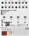
Product characteristics
• Separate calculation of the active power and the active power for each measuring channel
• Event or time-controlled transmission of measured value telegrams to the eNet server
• Fully-encrypted radio transmission (AES-CCM) from eNet Server software version 2.0
• Update of the device software
Technical data
Rated voltage: AC 230 V ~, 50/60 Hz
Rated load current: 16 A
Peak current (1 s): 80 A
Peak current (1 min): 24 A
Power consumption per channel: 225 mW
Ambient temperature: −5 ... +45 °C
Transmission interval: 1 ... 60 min
Connection of load terminals: screw terminals
single wire: 1 x 1.5 ... 4 mm2
stranded without ferrule: 1 x 0.75 ... 4 mm2
stranded with ferrule: 1 x 0.5 ... 2.5 mm2
Mounting width: 72 mm (4 rail units)
Bus line
Rated voltage: DC 12 V SELV
Current consumption: 10 mA
Connection bus: terminal
Cable length: max. 3 m
Measuring ranges per channel
Current: 0 mA ... 16 A
Accuracy (current): ± 0.5 % of the current value and ± 8 mA
Voltage: 207 ... 250 V
Accuracy (voltage): ± 0.5 % of the current value
Transmitted power and energy values
Active power: −4,000 ... 4,000 W
Apparent power: 0 ... 4000 VA
Reactive power: −4,000 ... 4,000 var
Accuracy (power): ± 0.5 % of the current value and ± 2 W/VA/var
Active energy: −99,999 ... 99,999 kWh
eNet radio switch/push-button actuator 1-gang mini
Ref.-no.
New system feature: Fully-encrypted radio transmission (AES-CCM) from eNet Server software version 2.0
Intended use
• Switching of lighting
• Operation with suitable eNet radio transmitters
• Installation in flush box according to EN 60670-1 in combination with a suitable cover
• Mounting in surface-mounted housing or mounting adapter (ref.-no. FM-EBG) for false ceilings
Product characteristics
• Operating mode switch for: switch/push-button actuator or parameterisation via eNet server
• Status feedback to radio transmitter
• Scene operation possible
• Switchable output with Prog button
• Status indication with LED
Switching operation:
• Switch-on telegram: Device switches on
• Switch-off telegram: Device switches off

Push-button operation:
• Relay contact remains closed as long as ON or OFF telegrams are being received
• The maximum switch-on time is 60 seconds
Can be set with eNet server:
• Flash function
• Run-on time
• Switch-on delay / switch-off delay
• Operation as NO or NC contacts
• Switch-off warning
• Minimum switching repeat time
• Operating locks
• Continuous on, Continuous off
Supplementary functions with eNet server:
• Fully-encrypted radio transmission (AES-CCM) from eNet Server software version 2.0
• Update of the device software
• Repeater function
• Reading of error memory
Technical data
Rated voltage: AC 230 V ~, 50/60 Hz
Ambient temperature: −25 ... +70 °C
Switching current at 35 °C
Ohmic: 16 A (AC1)
For switching current > 10 A connecting cable 2.5 mm2
Fluorescent lamps: 4 AX
Contact type: µ
Stand-by power: 0.5 W
Connected load at 35 °C
Incandescent lamps: 2300 W
HV halogen lamps: 2000 W
Electronic transformers: 1500 W
Inductive transformers: 1000 VA
HV LED lamps: typical 500 W
Compact fluorescent lamps: typical 500 W
Fluorescent lamps
non-compensated: 920 VA
Capacitive load: 690 VA (560 µF)
Connection mode: screw terminals
single wire: 1 x 0.75 ... 4 mm2

stranded with ferrule: 1 x 0.75 ... 2.5 mm2
Dimensions (Ø x H): 53 x 28 mm
Radio frequency: 868.0 ... 868.6 MHz
Transmitting power: max. 20 mW
Transmission range in free field: typical 100 m
Receiver category: 2
eNet radio switch/push-button actuator with floating contact, 1-gang mini New system feature: Fully-encrypted radio transmission (AES-CCM) from eNet Server software version 2.0
Intended use
• Switching of lighting
• Operation with suitable eNet radio transmitters
• Installation in flush box according to EN 60670-1 in combination with a suitable cover
• Mounting in surface-mounted housing or mounting adapter (ref.-no. FM-EBG) for false ceilings
Product characteristics
• Operating mode switch for: switch/push-button actuator or parameterisation via eNet server
• Status feedback to radio transmitter
• Scene operation possible
• Switchable output with Prog button
• Status indication with LED
Switching operation:
• Switch-on telegram: Device switches on
• Switch-off telegram: Device switches off

Push-button operation:
• Relay contact remains closed as long as ON or OFF telegrams are being received
• The maximum switch-on time is 60 seconds
Can be set with eNet server:
• Flash function
• Run-on time
• Switch-on delay / switch-off delay
• Operation as NO or NC contacts
• Switch-off warning
• Minimum switching repeat time
• Operating locks
• Continuous on, Continuous off
Supplementary functions with eNet server:
• Fully-encrypted radio transmission (AES-CCM) from eNet Server software version 2.0
• Update of the device software
• Repeater function
• Reading of error memory
Technical data
Rated voltage: AC 230 V ~, 50/60 Hz
Ambient temperature: −25 ... +70 °C
Switching current at 35 °C
Ohmic: 16 A (AC1)
For switching current > 10 A connecting cable 2.5 mm2
Fluorescent lamps: 4 AX
Contact type: µ
Stand-by power: 0.5 W
Connected load at 35 °C
Incandescent lamps: 2300 W
HV halogen lamps: 2000 W
Electronic transformers: 1500 W
Inductive transformers: 1000 VA
HV LED lamps: typical 500 W
Compact fluorescent lamps: typical 500 W
Fluorescent lamps
non-compensated: 920 VA
Capacitive load: 690 VA (560 µF)
Connection mode: screw terminals
single wire: 1 x 0.75 ... 4 mm2
stranded with ferrule: 1 x 0.75 ... 2.5 mm2
Dimensions (Ø x H): 53 x 28 mm
Radio frequency: 868.0 ... 868.6 MHz
Transmitting power: max. 20 mW
Transmission range in free field: typical 100 m
Receiver category: 2
eNet radio switch/push-button actuator 2-gang mini
Ref.-no.
New system feature: Fully-encrypted radio transmission (AES-CCM) from eNet Server software version 2.0
Intended use
• Switching of lighting and single-phase motors
• Operation with suitable eNet radio transmitters
• Installation in flush box according to EN 60670-1 in combination with a suitable cover
• Mounting in surface-mounted housing or mounting adapter (ref.-no. FM-EBG) for false ceilings
Product characteristics
• Operating mode switch for: switch/push-button actuator together for both outputs or parameterisation via eNet server
• Independent switching of two electrical loads
• Status feedback to radio transmitter
• Scene operation possible
• Status indication with LED
Switching operation:
• Switch-on telegram: Device switches on
• Switch-off telegram: Device switches off

Technical data
Push-button operation:
• Relay contact remains closed as long as ON or OFF telegrams are being received
• The maximum switch-on time is 60 seconds
Can be set with eNet server for each output:
• Flash function
• Run-on time
• Switch-on delay / switch-off delay
• Operation as NO or NC contacts
• Switch-off warning
• Minimum switching repeat time
• Operating locks
• Continuous on, Continuous off
Supplementary functions with eNet server:
• Fully-encrypted radio transmission (AES-CCM) from eNet Server software version 2.0
• Update of the device software
• Repeater function
• Reading of error memory
Rated voltage: AC 230 V ~, 50/60 Hz
Ambient temperature: −25 ... +70 °C
Switching current at 35 °C
Ohmic: 16 A (AC1)
For switching current > 10 A connecting cable 2.5 mm2
Current carrying capacity of device: Σ 16 A
Fluorescent lamps: 4 AX
Contact type: µ
Stand-by power: max. 0.5 W
Connected load per output at 35 °C
Incandescent lamps: 2300 W
HV halogen lamps: 2000 W
Electronic transformers: 1500 W
Inductive transformers: 1000 VA
HV LED lamps: typical 500 W
Compact fluorescent lamps: typical 500 W
Fluorescent lamps
non-compensated: 920 VA
Motors: 450 VA
Capacitive load: 690 VA (560 µF)
Connection mode: screw terminals
single wire: 1 x 0.75 ... 4 mm2
stranded with ferrule: 1 x 0.75 ... 2.5 mm2
Dimensions (Ø x H): 53 x 28 mm
Radio frequency: 868.0 ... 868.6 MHz
Transmitting power: max. 20 mW
Transmission range in free field: typical 100 m
Receiver category: 2
eNet radio blinds actuator 1-gang mini
New system feature: Fully-encrypted radio transmission (AES-CCM) from eNet Server software version 2.0
Intended use
• Controlling electrically driven blinds, shutters and awnings
• Operation with suitable eNet radio transmitters
• Installation in flush box according to EN 60670-1 in combination with a suitable cover
• Mounting in surface-mounted housing or mounting adapter (ref.-no. FM-EBG) for false ceilings
Product characteristics
• Operating mode switch for switch-over to blind actuator, shutter actuator or parameterisation via eNet server
• Positioning of the blind and slats via scene recall
• Position for sun protection and twilight can be saved
• Status feedback to radio transmitter
• Switchable output with Prog button
• Blind/shutter running time can be saved
• Slat change-over time can be saved
• Fabric-stretching for awnings
• Status indication with LED
Can be set with eNet server:
• Change-over time for direction change
• Running direction invertible
• Operating locks
• Position for sun protection, twilight, lock-out protection and wind alarm

Supplementary functions with eNet server:
• Fully-encrypted radio transmission (AES-CCM) from eNet Server software version 2.0
• Update of the device software
• Repeater function
• Reading of error memory
Technical data
Rated voltage: AC 230 V ~, 50/60 Hz
Ambient temperature: −25 ... +70 °C
Minimum actuation time in operating mode
Blind: 0.1 s
Shutter: 0.3 s
Contact type: µ
Stand-by power: max. 0.5 W
Running time: 1 ... 600 s
Running time default setting: 120 s
Slat adjusting time: 0 ... 10 s
Connected load
Motors: 1000 W
Connection mode: screw terminals single wire: 1 x 0.75 ... 4 mm2 stranded with ferrule: 1 x 0.75 ... 2.5 mm2
Dimensions (Ø x H): 53 x 28 mm
Radio frequency: 868.0 ... 868.6 MHz
Transmitting power: max. 20 mW
Transmission range in free field: typical 100 m
Receiver category: 2
eNet radio dimming actuator 1-gang mini
Ref.-no.
New system feature: Fully-encrypted radio transmission (AES-CCM) from eNet Server software version 2.0

Intended use
• Switching and dimming of incandescent lamps, HV halogen lamps, electronic transformers for halogen or LED lamps, dimmable inductive transformers for halogen or LED lamps, HV LED or compact fluorescent lamps • Operation with suitable eNet radio transmitters • Installation in flush box according to EN 60670-1 in combination with a suitable cover • Mounting in surfacemounted housing or mounting adapter (ref.-no. FM-EBG) for false ceilings
Product characteristics
• Switch-on via bulb-preserving soft start
• Switch-on brightness can be saved permanently
• Minimum brightness can be saved permanently • Scene operation possible • Status indication with LED • Status feedback to radio transmitter • Switchable with Prog button • Electronic short-circuit protection with permanent switch-off after 7 seconds at the latest • Electronic overtemperature protection • Automatic or manual setting of the dimming principle suitable for the load
• Power extension possible by means of power boosters (ref.-no. ULZ 1755 REG) • Optional accessory: compensation module LED, ref.-no.: KM LED 230 U
Can be set with eNet server:
• Maximum brightness • Dimming speed • Switch-on delay / switch-off delay • Dim up/dim down ramp • Switch-off warning • Operating locks • Continuous on, Continuous off • Hotel function
• Run-on time Supplementary functions with eNet server: • Fully-encrypted radio transmission (AES-CCM) from eNet Server software version 2.0 • Update of the device software • Repeater function
• Reading of error memory
Technical data
Rated voltage:
AC 230 V ~, 50/60 Hz
Power loss: max. 1.5 W
Stand-by power: max. 0.5 W
Ambient temperature: −25 ... +70 °C
Connected load at 45 °C
Power specifications including transformer power dissipation. Operate inductive transformers with at least 85 % nominal load. For ohmic-inductive mixed load, maximum 50 % proportion of ohmic load. Otherwise incorrect calibration of the dimmer may result.
Incandescent lamps: 20 ... 250 W
HV halogen lamps: 20 ... 250 W
Electronic transformers: 20 ... 250 W
Electronic transformers with LV LED: typical 20 ... 100 W
Inductive transformers: 20 ... 250 VA
Inductive transformers with LV LED: typical 20 ... 100 VA
Dimmable HV LED lamps: typical 3 ... 70 W
Dimmable compact fluorescent lamps: typical 3 ... 70 W
Ohmic-inductive: 20 ... 250 VA
Ohmic-capacitive: 20 ... 250 W
Capacitive-inductive: not permitted
Ohmic and HV LED: typical 3 ... 70 W
Ohmic and CFL: typical 3 ... 70 W
Reduction of load for every 5 °C exceededing 45 °C: –5 % for installation into wooden or hollow walls: −15 % for installation into multiple combinations: −20 %
Amplifiers: see instructions for amplifier Connection mode: screw terminals single wire: 1 x 0.75 ... 4 mm2 stranded with ferrule: 1 x 0.75 ... 2.5 mm2
Contact type: ε
Total length power cable: max. 100 m
Dimensions (Ø x H): 53 x 28 mm
Radio frequency: 868.0 ... 868.6 MHz
Transmitting power: max. 20 mW
Transmission range in free field: typical 100 m
Receiver category: 2
eNet radio push-button controller 1 – 10 V 1-gang mini
New system feature: Fully-encrypted radio transmission (AES-CCM) from eNet Server software version 2.0
Intended use
• Switching and brightness setting of luminaires with 1 – 10 V interface

• Operation with suitable eNet radio transmitters
• Installation in flush box according to EN 60670-1 in combination with a suitable cover
• Mounting in surface-mounted housing or mounting adapter (ref.-no. FM-EBG) for false ceilings
Product characteristics
• Switch-on brightness can be saved permanently
• Minimum brightness can be saved permanently
• Scene operation possible
• Status indication of the 1 – 10 V subscribers via LED
• Status feedback to radio transmitter
• 1 – 10 V subscribers switchable with Prog button
• 1 – 10 V interface is protected against reverse polarity
Can be set with eNet server:
• Maximum brightness
• Dimming speed
• Switch-on delay / switch-off delay
• Dim up/dim down ramp
• Switch-off warning
• Operating locks
• Continuous on, Continuous off
• Hotel function
• Run-on time
Supplementary functions with eNet server:
• Fully-encrypted radio transmission (AES-CCM) from eNet Server software version 2.0
• Update of the device software
• Repeater function
• Reading of error memory
Technical data
Rated voltage: AC 230 V ~, 50/60 Hz
Stand-by power: max. 0.5 W
Ambient temperature: −25 ... +70 °C
Contact type: µ
Control voltage: 0.5 ... 11 V
Control current: max. 50 mA
Switching current
Ohmic: 6 A
Fluorescent lamps: 3 AX
Connected load
Ohmic load: 1380 W
Capacitive load: 690 VA (560 µF)
Connection mode: screw terminals
single wire: 1 x 0.75 ... 4 mm2
stranded with ferrule: 1 x 0.75 ... 2.5 mm2
Dimensions (Ø x H): 53 x 28 mm
Total length power cable: max. 100 m
Total length of control cable: max. 100 m
Radio frequency: 868.0 ... 868.6 MHz
Transmitting power: max. 20 mW
Transmission range in free field: typical 100 m
Receiver category: 2
eNet radio DALI gateway 1-gang mini
Ref.-no.
New system feature: Fully-encrypted radio transmission (AES-CCM) from eNet Server software version 2.0
Intended use
• Switching and brightness setting for luminaires with DALI interface

• Operation with suitable eNet radio transmitters
• Installation in flush box according to EN 60670-1 in combination with a suitable cover
• Mounting in surface-mounted housing or mounting adapter (ref.-no. FM-EBG) for false ceilings
Product characteristics
• Joint operation of all the connected DALI ballasts, broadcast
• Electronic short-circuit protection of the DALI supply with permanent switch-off after 8 seconds
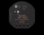
• Electronic over-temperature protection of the DALI supply with self-retain
• DALI supply for a maximum of 12 subscribers
• Parallel switching of up to 6 DALI control units with the option of supplying up to 72 DALI subscribers
• Switch-on brightness can be saved permanently
• Minimum brightness can be saved permanently
• Scene operation possible
Technical data
• Status indication with LED
• Status feedback to radio transmitter
• DALI ballast is switchable with Prog button
Can be set with eNet server:
• Maximum brightness
• Dimming speed
• Switch-on delay / switch-off delay
• Dim up/dim down ramp
• Switch-off warning
• Operating locks
• Continuous on, Continuous off
• Hotel function
• Run-on time
Supplementary functions with eNet server:
• Fully-encrypted radio transmission (AES-CCM) from eNet Server software version 2.0
• Update of the device software
• Repeater function
• Reading of error memory
Rated voltage: AC 230 V ~, 50/60 Hz
Power consumption: max. 2 W
Ambient temperature: −25 ... +70 °C
DALI system voltage: DC 16 V
Output current: max. 24 mA
Number of DALI devices: max. 12
Reduction of load
Number of DALI devices over 45 °C: max. 8
Number of control units in parallel: max. 6
Connection mode: screw terminals single wire: 1 x 0.75 ... 4 mm2 stranded with ferrule: 1 x 0.75 ... 2.5 mm2
Dimensions (Ø x H): 53 x 28 mm
Radio frequency: 868.0 ... 868.6 MHz
Transmitting power: max. 20 mW
Transmission range in free field: typical 100 m
Receiver category: 2
The mounting adapter is equipped with a strain relief and a cover for the contact terminals. It enables the installation of mini actuators into false ceilings or on DIN rails.
Dimensions: 97 x 53 x 36 mm
eNet master receiver module for rail mounting
Rail mounting device, 2 rail units
New system feature: Fully-encrypted radio transmission (AES-CCM) from eNet Server software version 2.0

Intended use
• Radio receiver for flush-mounted series modules
• Operation with power supply, ref.-no.: NT 1220 REG VDC


• Mounting on DIN rail according to EN 60715 in distribution boxes
Product characteristics
• Integrated antenna
• External antenna (ref.-no.: FM ANT) can additionally be connected in case of disadvantageous installation conditions, e.g. metallic distribution boxes
Technical data
Rated voltage: DC 12 V SELV
Current consumption: typical 15 mA
Ambient temperature: −5 ... +45 °C
Protection class: III
Mounting width: 36 mm (2 rail units)
Number of RMD modules: max. 32
Connection bus: terminal
Cable length: max. 3 m

Cable type: J-Y(St)Y 2 x 2 x 0.8 mm
Radio frequency: 868.0 ... 868.6 MHz
Radio range: typical 100 m
Transmitting power: max. 20 mW
Receiver category: 2
eNet antenna
Intended use
FM
The antenna with magnetic pedestal supplements the integrated antenna of the master receiver for rail mounting and eNet server in case of unfavourable installation conditions, e.g. a metallic distribution box.
Technical data
Antenna length: 17 cm
Cable length: 1.4 m
Connection: SMB connector
Radio frequency: 868.0 ... 868.6 MHz
Power supply for rail mounting for eNet master receiver ref.-no.: FM FK 32 REG
Rail mounting device, 2 rail units
Technical data
Input voltage: AC 100 ... 240 V ~, 50/60 Hz
Input current: 505 mA
Output voltage: DC 12 V
Output current: 2 A
Mounting width: 36 mm (2 rail units)
Connection: screw terminals
NT 1220 REG VDC
Ref.-no.
eNet radio switch/push-button actuator 1-gang, for rail mounting
Rail mounting device, 2 rail units
New system feature: Fully-encrypted radio transmission (AES-CCM) from eNet Server software version 2.0
Intended use
• Switching of lighting
• Operation with suitable eNet radio transmitters
• Operation with power supply (ref.-no. NT 1220 REG VDC) and receiver module (ref.-no. FM FK 32 REG) or eNet server
• Installation in distribution boxes on DIN rail according to EN 60715
Product characteristics
• Operating mode switch for: switch/push-button actuator or parameterisation via eNet server
• Status feedback to radio transmitter
• Scene operation possible
• Switchable output with Prog button
• Status indication with LED
Switching operation:
• Switch-on telegram: Device switches on
• Switch-off telegram: Device switches off

Technical data
Push-button operation:
• Relay contact remains closed as long as ON or OFF telegrams are being received
• The maximum switch-on time is 60 seconds
Can be set with eNet server:
• Flash function
• Run-on time
• Switch-on delay / switch-off delay
• Operation as NO or NC contacts
• Switch-off warning
• Minimum switching repeat time
• Operating locks
• Continuous on, Continuous off
Supplementary functions with eNet server:
• Fully-encrypted radio transmission (AES-CCM) from eNet Server software version 2.0
• Update of the device software
• Reading of error memory
Rated voltage: AC 230 V ~, 50/60 Hz
Ambient temperature: −5 ... +45 °C
Switching current at AC 230 V ~
Ohmic: 16 A
For switching current > 10 A connecting cable 2.5 mm2
Fluorescent lamps: 4 AX
Contact type: µ
Stand-by power: max. 0.2 W
Connected load
Incandescent lamps: 2300 W
HV halogen lamps: 2000 W
Electronic transformers: 1500 W

HV LED lamps: typical 500 W
Compact fluorescent lamps: typical 500 W
Inductive transformers: 1000 VA
Fluorescent lamps
non-compensated: 920 VA
Capacitive load: 690 VA (560 µF)
Connection, outputs
Connection mode: screw terminals
single wire: 1 x 1.5 ... 4 mm2
stranded without ferrule: 1 x 0.75 ... 4 mm2
stranded with ferrule: 1 x 0.5 ... 2.5 mm2
Mounting width: 36 mm (2 rail units)
Bus line
Rated voltage: DC 12 V SELV
Current consumption: max. 20 mA
Connection bus: terminal
Cable length: max. 3 m
Ref.-no.
eNet radio switch/push-button actuator 8-gang / blinds actuator 4-gang, for rail mounting Rail mounting device, 4 rail units New system feature: Fully-encrypted radio transmission (AES-CCM) from eNet Server software version 2.0
Intended use
• Switching of lighting
• Switching of single-phase fan motors
• Controlling electrically driven blinds, shutters and awnings
• Operation with suitable eNet radio transmitters
• Operation with power supply (ref.-no. NT 1220 REG VDC) and receiver module (ref.-no. FM FK 32 REG) or eNet server
• Installation in distribution boxes on DIN rail according to EN 60715
Product characteristics
• Operating mode switch for switch-over of switch actuator, push-button actuator, blind actuator, shutter actuator or configuration via eNet server
• Status feedback to radio transmitter
• Scene operation possible
• Outputs switchable with Prog button
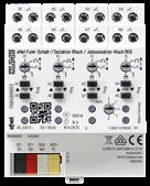
• Status indication of the outputs via LED
Switching operation:
• Switch-on telegram: Device switches on
• Switch-off telegram: Device switches off
Push-button operation:
• Relay contact remains closed as long as ON or OFF telegrams are being received
• The maximum switch-on time is 60 seconds
Operating mode "Venetian blind/Rolling shutter":
• Positioning of the blind and slats via scene recall
• Position for sun protection and twilight can be saved
• Blind/shutter running time can be saved
• Slat change-over time can be saved
• Fabric-stretching for awnings
Can be set with eNet server in switching/push-button operation:
• Operating mode for each output can be set separately
• Flash function
• Run-on time
• Switch-on delay / switch-off delay
• Operation as NO or NC contacts
• Switch-off warning
• Minimum switching repeat time
• Operating locks
• Continuous on, Continuous off
Can be set in the operating mode "Venetian blind/Rolling shutter" with eNet server:
• Change-over time for direction change
• Running direction invertible
• Operating locks
• Position for sun protection, twilight, lock-out protection and wind alarm

Supplementary functions with eNet server:
• Fully-encrypted radio transmission (AES-CCM) from eNet Server software version 2.0
• Update of the device software
• Reading of error memory
Technical data
Rated voltage: AC 230 V ~, 50/60 Hz
Ambient temperature: −5 ... +45 °C
Switching voltage: AC 250 V ~
Minimum actuation time in operating mode

Blind: 0.1 s
Shutter: 0.3 s
Running time: 1 ... 600 s
Running time default setting: 120 s
Slat adjusting time: 0 ... 10 s
Switching current per output for AC 230 V ~
Ohmic: 16 A (AC1)
For switching current
> 10 A connecting cable 2.5 mm2
Fluorescent lamps: 4 AX
Switching current neighbouring load outputs: Σ 20 A
Current carrying capacity of device: max. 80 A
Contact type: µ
Stand-by power: max. 0.5 W
Connected load per output
Motors: 1000 W
Incandescent lamps: 2300 W
HV halogen lamps: 2000 W
Electronic transformers: 1500 W
Inductive transformers: 1000 VA
HV LED lamps: typical 500 W
Compact fluorescent lamps: typical 500 W
Fluorescent lamps
non-compensated: 920 VA
Capacitive load: 690 VA (560 µF)
Connection, outputs Connection mode: screw terminals
Mounting width: 72 mm (4 rail units)
Bus line
Rated voltage: DC 12 V SELV
Current consumption: 60 mA
Connection bus: terminal Cable length: max. 3 m
eNet radio blinds actuator 1-gang, for rail mounting Rail mounting device, 2 rail units New system feature: Fully-encrypted radio transmission (AES-CCM) from eNet Server software version 2.0
Intended use
• Controlling electrically driven blinds, shutters and awnings
• Operation with suitable eNet radio transmitters
• Operation with power supply (ref.-no. NT 1220 REG VDC) and receiver module (ref.-no. FM FK 32 REG) or eNet server
• Installation in distribution boxes on DIN rail according to EN 60715

Product characteristics
• Operating mode switch for switch-over to blind actuator, shutter actuator or parameterisation via eNet server
• Positioning of the blind and slats via scene recall
• Position for sun protection and twilight can be saved
• Status feedback to radio transmitter
• Switchable output with Prog button
• Blind/shutter running time can be saved
• Slat change-over time can be saved
• Fabric-stretching for awnings
• Status indication with LED
Can be set with eNet server:
• Change-over time for direction change
• Running direction invertible
• Operating locks
• Position for sun protection, twilight, lock-out protection and wind alarm

Supplementary functions with eNet server:
• Fully-encrypted radio transmission (AES-CCM) from eNet Server software version 2.0
• Update of the device software
• Reading of error memory
Technical data
Rated voltage: AC 230 V ~, 50/60 Hz
Ambient temperature: −5 ... +45 °C
Minimum actuation time in operating mode
Blind: 0.1 s Shutter: 0.3 s
Contact type: µ
Stand-by power: max. 0.2 W
Running time: 1 ... 600 s
Running time default setting: 120 s
Slat adjusting time: 0 ... 10 s
Connected load Motors: 1000 W
Connection of load terminals: screw terminals single wire: 1 x 1.5 ... 4 mm2 stranded without ferrule: 1 x 0.75 ... 4 mm2 stranded with ferrule: 1 x 0.5 ... 2.5 mm2
Mounting width: 36 mm (2 rail units)
Bus line
Rated voltage: DC 12 V SELV
Current consumption: max. 20 mA
Connection bus: terminal
Cable length: max. 3 m

Ref.-no.
eNet radio dimming actuator 1-gang, for rail mounting
Rail mounting device, 2 rail units
New system feature: Fully-encrypted radio transmission (AES-CCM) from eNet Server software version 2.0
Intended use
• Switching and dimming of incandescent lamps, HV halogen lamps, electronic transformers for halogen or LED lamps, dimmable inductive transformers for halogen or LED lamps, HV LED or compact fluorescent lamps
• Operation with power supply (ref.-no. NT 1220 REG VDC) and receiver module (ref.-no. FM FK 32 REG) or eNet server
• Operation with suitable eNet radio transmitters
• Installation in distribution boxes on DIN rail according to EN 60715
Product characteristics
• Switch-on via bulb-preserving soft start
• Switch-on brightness can be saved permanently
• Minimum brightness can be saved permanently
• Scene operation possible
• Status indication with LED
• Status feedback to radio transmitter
• Switchable with Prog button
• Electronic short-circuit protection with permanent switch-off after 7 seconds at the latest
• Electronic over-temperature protection

• Automatic or manual setting of the dimming principle suitable for the load
• Power extension possible by means of power boosters (ref.-no. ULZ 1755 REG)
• Optional accessory: compensation module LED, ref.-no.: KM LED 230 U

Can be set with eNet server:
• Maximum brightness
• Dimming speed
• Switch-on delay / switch-off delay
• Dim up/dim down ramp
• Switch-off warning
• Operating locks
• Continuous on, Continuous off
• Hotel function
• Run-on time
Supplementary functions with eNet server:
• Fully-encrypted radio transmission (AES-CCM) from eNet Server software version 2.0
• Update of the device software
• Reading of error memory
Technical data
Rated voltage: AC 230 V ~, 50/60 Hz
Power loss: max. 4 W
Stand-by power: max. 0.3 W
Ambient temperature: −5 ... +45 °C
Connected load at 35 °C
Power specifications including transformer power dissipation.
Operate inductive transformers with at least 85 % nominal load. For ohmic-inductive mixed load, maximum 50 % proportion of ohmic load. Otherwise incorrect calibration of the dimmer may result.
Incandescent lamps: 20 ... 500 W
HV halogen lamps: 20 ... 500 W
Electronic transformers: 20 ... 500 W
Electronic transformers with LV LED: typical 20 ... 100 W
Inductive transformers: 20 ... 500 VA
Inductive transformers with LV LED: typical 20 ... 100 VA
Dimmable HV LED lamps: typical 3 ... 100 W
Dimmable compact fluorescent lamps: typical 3 ... 100 W
With setting "LED trailing edge phase control" the max. connection power for HV LED lamps and electronic transformers with LV LED doubles.
Ohmic-inductive: 20 ... 500 VA
Ohmic-capacitive: 20 ... 500 VA
Capacitive-inductive: not permitted
Ohmic and HV LED: typical 3 ... 100 W
Ohmic and CFL: typical 3 ... 100 W
Reduction of load for every 5 °C
exceededing 35 °C: −5 %

Amplifiers: see instructions for amplifier
Connection, outputs
Connection mode: screw terminals single wire: 1 x 1.5 ... 4 mm2 stranded without ferrule: 1 x 0.75 ... 4 mm2 stranded with ferrule: 1 x 0.5 ... 2.5 mm2
Contact type: ε
Length of output cable, per channel: max. 100 m
Mounting width: 36 mm (2 rail units)
Bus line
Rated voltage: DC 12 V SELV
Current consumption: 10 mA
Connection bus: terminal Cable length: max. 3 m
Ref.-no.
eNet radio dimming actuator 4-gang, for rail mounting
Rail mounting device, 8 rail units
New system feature: Fully-encrypted radio transmission (AES-CCM) from eNet Server software version 2.0
FM
Intended use
• Switching and dimming of incandescent lamps, HV halogen lamps, electronic transformers for halogen or LED lamps, dimmable inductive transformers for halogen or LED lamps, HV LED or compact fluorescent lamps
• Operation with power supply (ref.-no. NT 1220 REG VDC) and receiver module (ref.-no. FM FK 32 REG) or eNet server
• Operation with suitable eNet radio transmitters
• Installation in distribution boxes on DIN rail according to EN 60715
Product characteristics
• Switch-on via bulb-preserving soft start
• Switch-on brightness for each output can be saved permanently
• Minimum brightness for each output can be saved permanently
• Scene operation possible
• Status indication of the outputs via LED
• Status feedback to radio transmitter
• Outputs switchable with Prog button
• Increase in output power possible through parallel switching of multiple outputs
• Electronic short-circuit protection with permanent switch-off after 7 seconds at the latest
• Electronic over-temperature protection

• Automatic or manual setting of the dimming principle suitable for the load
• Power extension possible by means of power boosters (ref.-no. ULZ 1755 REG)
• Optional accessory: compensation module LED, ref.-no.: KM LED 230 U
Can be set with eNet server:
• Maximum brightness
• Dimming speed
• Switch-on delay / switch-off delay
• Dim up/dim down ramp
• Switch-off warning
• Operating locks
• Continuous on, Continuous off
• Hotel function
• Run-on time
Supplementary functions with eNet server:
• Fully-encrypted radio transmission (AES-CCM) from eNet Server software version 2.0
• Update of the device software
• Reading of error memory
Technical data
Rated voltage: AC 230 V ~, 50/60 Hz
Power loss: max. 8 W
Stand-by power: max. 1.2 W
Ambient temperature: −5 ... +45 °C
Connected load per output at 45 °C
Power specifications including transformer power dissipation.
Operate inductive transformers with at least 85 % nominal load. For ohmic-inductive mixed load, maximum 50 % proportion of ohmic load. Otherwise incorrect calibration of the dimmer may result.
Max. load for outputs connected in parallel is limited to 95 %.
The minimum load of parallel switching of load outputs is 250 VA.
Incandescent lamps: 20 ... 250 W
HV halogen lamps: 20 ... 250 W
Electronic transformers: 20 ... 250 W
Electronic transformers with LV LED: typical 20 ... 100 W
Inductive transformers: 20 ... 250 VA
Inductive transformers with LV LED: typical 20 ... 100 VA
Dimmable HV LED lamps: typical 3 ... 50 W
Dimmable compact fluorescent lamps: typical 3 ... 50 W
With setting "LED trailing edge phase control" the max. connection power for HV LED lamps and electronic transformers with LV LED doubles.
Ohmic-inductive: 20 ... 250 VA
Ohmic-capacitive: 20 ... 250 VA

Capacitive-inductive: not permitted
Amplifiers: see instructions for amplifier
Connection, outputs
Connection mode: screw terminals
single wire: 1 x 1.5 ... 4 mm2
stranded without ferrule: 1 x 0.75 ... 4 mm2
stranded with ferrule: 1 x 0.5 ... 2.5 mm2
Contact type: ε
Length of output cable, per channel: max. 100 m
Mounting width: 144 mm (8 rail units)
Bus line
Rated voltage: DC 12 V SELV
Current consumption: 10 mA
Connection bus: terminal
Cable length: max. 3 m
Ref.-no.
eNet server for rail mounting Rail mounting device, 6 rail units including plug-in power supply (ref.-no. ST NT 12 VDC) for provisional operation at construction site New system feature: Fully-encrypted radio transmission (AES-CCM) from eNet Server software version 2.0
Intended use
• Commissioning, diagnosis and maintenance of an eNet installation via PC, tablet and laptop

• Operation of an eNet installation via smartphone
• Radio receiver for eNet RMD modules
• Operation only with approved power supply
• Mounting on DIN rail according to EN 60715 in distribution boxes with power supply RMD (ref.-no. NT 1220 REG VDC)
• Mobile use of the eNet server with plug-in power supply (ref.-no. ST NT 12 VDC)
Product characteristics
• Internal eNet radio and WLAN antenna
• External eNet radio and WLAN antennas for extending the radio ranges can additionally be connected
• LEDs for signalling
• Buttons for construction site mode and restart of the eNet server
• Electrical separation between the connections of the external antennas and the Ethernet connection
• Fully-encrypted radio transmission (AES-CCM) from eNet Server software version 2.0
Technical data
Rated voltage: DC 12 V SELV
Current consumption: 400 mA
Power consumption
Operation: max. 6 W
Stand-by: max. 2 W
Ambient temperature: −5 ... +45 °C
Storage/transport temperature: −20 ... +70 °C
Relative humidity: 20 ... 70 % (no condensation)
Protection class: III
Mounting width: 108 mm (6 rail units)
Connection, power supply: terminal
LAN: RJ45 socket 8-pin
WLAN antenna, external: SMB connector
Bus line
Cable length: max. 3 m
Number of RMD modules: max. 32
IP communication
LAN: 10/100 Mbit/s Ethernet
WLAN: 2.4 GHz, IEEE 802.11g
IP connections: max. 8
eNet communication
Radio frequency: 868.0 ... 868.6 MHz
Transmission range in free field: typical 100 m
Transmitting power: max. 20 mW
Receiver category: 2
Plug-in power supply 12 V (Spare part)

Technical data
Rated voltage: AC 230/240 V ~, 50/60 Hz
Output voltage: DC 12 V
Output current: max. 1 A
Primary current: max. 130 mA
Connected load: 12 W
Efficiency: approx. 80 %
Ambient temperature: +5 ... +25 °C
ST NT 12 VDC
Power supply for rail mounting for eNet server ref.-no.: ENET-SERVER Rail mounting device, 2 rail units
Technical data
Input voltage: AC 100 ... 240 V ~, 50/60 Hz
Input current: 505 mA
Output voltage: DC 12 V
Output current: 2 A
Mounting width: 36 mm (2 rail units)
Connection: screw terminals
eNet antenna
Intended use
The antenna with magnetic pedestal supplements the integrated antenna of the master receiver for rail mounting and eNet server in case of unfavourable installation conditions, e.g. a metallic distribution box.
Technical data
Antenna length: 17 cm
Cable length: 1.4 m
Connection: SMB connector
Radio frequency: 868.0 ... 868.6 MHz
WLAN antenna antenna with magnetic pedestal
Intended use
The antenna with magnetic pedestal supplements the integrated antenna of the eNet server in case of unfavourable installation conditions, e.g. a metallic distribution box.
Technical data
Antenna length: 17 cm
Cable length: 1.4 m


Connection: SMB connector
Radio frequency: 2.4 GHz
eNet radio signal quality meter

Not suitable for encrypted radio transmission
Only with eNet server software up to version 1.4.
Product characteristics
• Display of the signal quality of a selected eNet device using LEDs
• Display of the signal quality of status messages using LEDs
• Display of radio signals of non-eNet radio transmitters in the 868.0 ... 868.6 MHz frequency band using LEDs
• Switch-on, switch-off of the repeater functions of network-operated actuators, transmitters and energy sensors
• Battery operation with one included lithium button cell (CR 2450N)
• Devices switches off after 5 minutes without actuation

Technical data
Rated voltage: DC 3 V
Battery type: 1 x lithium CR 2450N (included)

Ambient temperature: −5 ... +45 °C
Radio frequency: 868.0 ... 868.6 MHz
Transmission range in free field: max. 100 m
Transmitting power: max. 20 mW
Receiver category: 2
Smart Control 8 see page 699
Smart Control 5 for installation in walls, capacitive touch screen fanless, without rotating parts
Ref.-no.
black SC 5 SW
Intended use
• Visualisation and operation of system statuses and information on building automation
• For vertical installation
• Installation in flush box according to EN 60670-1
• Ensure correct orientation when installing the flush box. Mounting screws must be in vertical alignment. Product characteristics
• KNX visualisation in combination with Visu Pro Server (ref.-no.: JVP-SERVER-H2)
• KNX visualisation in combination with Smart Visu Server (ref.-no.: SV-SERVER-INT)

• Display of diagrams not possible
• eNet visualisation in combination with eNet server for rail mounting (ref.-no.: ENET-SERVER) with software version 2.2 or higher
• Door call function only in combination with Siedle Smart Gateway SG 650-.. or SG 150-..
• High performance HD screen
• Proximity sensor
• Graphical user interface
• Brightness level of display adapts automatically to ambient brightness

• Smart Gateway with integrated image storage
Technical data
Rated voltage: DC 24 V SELV
Rated capacity: 12 W
Screen diagonal: 127 mm / 5’’
Resolution: 720 x 1280
Frame dimensions (W x H): 81 x 132 mm
Power supply: PoE acc. to IEEE 802.3af or DC 24 V via external power supply (not included)
Processor: Cortex-A53
Loudspeaker: integrated
Microphone: integrated
LAN connections: 1 x 10/100 Mbit/s
Ambient temperature: 0 ... +30 °C
eNet server set Smart Control 5 consists of eNet-Server (ref.-no.: ENET-SERVER) and Smart Control 5 (ref.-no.: SC 5 SW) black ENET-S-SC 5 SW
Power supply for rail mounting for Smart Control ref.-no.: SC 5 SW

Rail mounting device, 4 rail units
Technical data
Input voltage: AC 100 ... 240 V ~, 50/60 Hz
Input current: 730 mA
Output voltage: DC 24 V SELV

Output current: 1.5 A
Mounting width: 72 mm (4 rail units)
Connection: screw terminals
Flush-mounted power supply for Smart Control ref.-no.: SC 5 SW
Technical data
Input voltage: AC 230 V ~, 50/60 Hz

Input current: 150 mA
Output voltage: DC 24 V
Output current: 500 mA
Dimensions (Ø x H): 54 x 32 mm
Connection: screw terminals
Ref.-no.
NT 2415 REG VDC
NT 2405 VDC

No smartphone needed: With the freely programmable JUNG wall-mounted transmitters, lamps from the Philips Hue lighting system can be controlled simply with the push of a button. The switches are compatible with the JUNG A and LS range and work without cables or battery. They are available compatible with the JUNG AS 550 and LS 990 switch ranges.
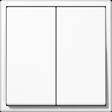
Friends of Hue switch set including mounting plate, adhesive film and fastening screw
• Smart switch for wireless remote control of Philips Hue lamps

• For switching, dimming and controlling individual light scenes
• For residential use only
• Mounting on flush box according to EN 60670-1, screw fixing on walls or adhesive fixing on smooth, even surfaces (glass)

• Battery-free device without external power supply
• Transmitting energy is generated from mechanical energy of actuation (energy harvesting)
• Encrypted transmission with device-specific code
• Wireless standard ZigBee Green Power, compatible with Friends of Hue and Apple HomeKit
• Automatic range extension via Philips Hue lamps
• Simple commissioning and configuration via Philips Hue app and Hue Bridge V2 or higher
Technical data
Radio frequency: 2.402 ... 2.480 GHz
Transmission range in free field: up to 175 m in buildings: approx. 20 m
Transmitting power: 7 dBm / 5 mW
Ambient temperature: −5 ... +45 °C
Storage/transport temperature: −25 ... +65 °C
Atmospheric humidity: 0 ... 95 % (no condensation)
A range
Friends of Hue switch set
4-channel max. 4 light scenes
including A 550 frame ref.: A 5581 BF WW
Thermoplastic (breakproof) high-gloss
white
LS range
Friends of Hue switch set
4-channel max. 4 light scenes
including LS 990 frame ref.: LS 981 WW
Thermoplastic (breakproof) high-gloss
white L FOHS LS 995 WW
Adhesive film for radio transmitter (Spare part)
• Adhesive fixing in indoor areas on window panes, walls or furniture

Wall-mounted transmitters with Bluetooth Low Energy operate lights and actuators from numerous manufacturers within compatible smart home systems. They are available in the JUNG A and LS ranges and work with battery-free EnOcean technology.
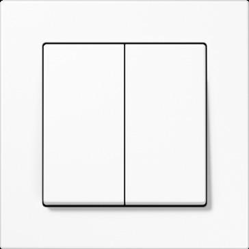
Ref.-no.
Bluetooth Low Energy radio transmitter including mounting plate, adhesive film and fastening screw
• Smart switch for wireless device control using wireless standard Bluetooth Low Energy (BLE) • For switching, dimming and controlling individual light scenes • Mounting on flush box according to EN 60670-1, screw fixing on walls or adhesive fixing on smooth, even surfaces (glass) • Battery-free device without external power supply • Transmitting energy is generated from mechanical energy of actuation (energy harvesting) • Encrypted transmission with AES-128 (CBC mode) and sequence counter • Compatible with these wireless Bluetooth systems: Casambi, XICATO Controls, Häfele Connect, WiSilica, Wirepas, Blu2Light (Vossloh Schwabe), Aruba, Fulham, Helvar • Configuration interface: NFC Forum Type 2 Tag (ISO/IEC 14443 Part 2 + 3) • Automatic range extension (depending on the system) via BT Mesh devices connected to the mains
Technical data
Radio frequency: 2.402 ... 2.480 GHz
Transmission range in free field: up to 75 m in buildings: approx. 10 m
A range
Bluetooth Low Energy radio transmitter
2-channel
Thermoplastic (breakproof) high-gloss
white
matt lacquered
Transmitting power: 0.4 dBm / 1.1 mW
Ambient temperature: −5 ... +45 °C
Storage/transport temperature: −25 ... +65 °C
Atmospheric humidity: 0 ... 95 % (no condensation)

L BLE A 590 WW
matt anthracite BLE A 590 ANM
4-channel
Thermoplastic (breakproof) high-gloss
white
matt lacquered
matt anthracite
LS range
Bluetooth Low Energy radio transmitter
2-channel
Thermoplastic (breakproof) high-gloss
white
black
4-channel
Thermoplastic (breakproof) high-gloss
white
black
Adhesive film for radio transmitter (Spare part)


• Adhesive fixing in indoor areas on window panes, walls or furniture
L BLE A 595 WW
BLE A 595 ANM
L BLE LS 990 WW
L BLE LS 990 SW
L BLE LS 995 WW
L BLE LS 995 SW
The flush-mounting radio transmitters without batteries in the JUNG design transmit switching, dimming and blind commands to radio receivers from the EnOcean system. They generate their transmission energy from the mechanical pressure when actuated.
 ENOCEAN FLUSH-MOUNTING RADIO TRANSMITTER
The JUNG EnOcean transmitters are compatible with all EnOcean receivers (EnOcean Ingredient Logo) – independent of the manufacturer. Via gateways the transmitters can also communicate with various bus systems, e.g. KNX.
EnOcean Technology
The idea that led to this innovative technology is based on a very simple observation. Where sensors record a measurement reading, the level of energy changes. Pressing a button a change of temperature or brightness – there is enough energy in processes like these to transmit wireless signals over a distance of up to 300 meters. The radio technology that transmits reading and switching signals without battery, consists essentially of two components: First, the locally available energy is converted into electrical energy (Energy Harvesting). Then an extremely low-power electronics prepares the data and sends short radio signals to a special receiver unit. The wireless protocol is optimised to transmit information at extremely low energy with maximum security.
EnOcean transmits radio signal with a frequency of 868 MHz.
Benefits
• Flexibility: no cabling, simple fitting and removal, e.g. switches on glass, stone, wood and furniture
• Simple planning of complex and flexible systems: optimal sensor positioning even for changing conditions of use
• Cost savings in installation, maintenance, renovation and energy use
• Environmentally friendly: far less cable material (copper, sheaths, etc.)
• Reduced risks through less fire load
• Subsequent fitting of wireless sensors in preservation listed buildings
• Interoperability: straightforward combination of products from a variety of manufacturers and for a wide selection of applications
• Scalability of the building system ensures a sustained building structure
• Time-savings: planning is speeded up, fast fitting, integration, configuration
• Service-free wireless sensors: no batteries needed, no replacement and disposal worries

• Little noise, dust and dirt
EnOcean radio transmitter including mounting plate, adhesive film and fastening screw Intended use
• Radio transmitter for the transmission of switching, dimming or shutter commands to radio receivers of the EnOcean radio system
• Mounting on flush box according to EN 60670-1, screw fixing on walls or adhesive fixing on smooth, even surfaces (glass)
Product characteristics
• Battery-free device without external power supply
• Transmitting energy is generated from mechanical energy of actuation (energy harvesting)
• Configuration interface: NFC Forum Type 2 Tag (ISO/IEC 14443 Part 2 + 3)
• Optional: Encrypted transmission with AES-128 and sequence counter
Technical data
Carrier frequency: 868 MHz (ASK)
Transmission range in free field: up to 300 m in buildings: approx. 30 m
Transmitting power: −1.9 dBm / 0.7 mW
Ambient temperature: −5 ... +45 °C
Storage/transport temperature: −25 ... +65 °C
Atmospheric humidity: 0 ... 95 % (no condensation)
The JUNG EnOcean transmitters are compatible with all EnOcean receivers (EnOcean Ingredient Logo) – independent of the manufacturer. Via gateways the transmitters can also communicate with various bus systems, e.g. KNX.



AS and

The JUNG EnOcean transmitters are compatible with all EnOcean receivers (EnOcean Ingredient Logo) – independent of the manufacturer. Via gateways the transmitters can also communicate with various bus systems, e.g. KNX.


EnOcean radio transmitter with symbols 0 I


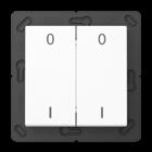
Thermoplastic (breakproof) high-gloss
EnOcean radio transmitter with symbols ▲▼
Thermoplastic (breakproof) high-gloss
EnOcean radio transmitter with symbols 0 I and ▲▼
Thermoplastic (breakproof) high-gloss

The JUNG EnOcean transmitters are compatible with all EnOcean receivers (EnOcean Ingredient Logo) – independent of the manufacturer. Via gateways the transmitters can also communicate with various bus systems, e.g. KNX.

EnOcean radio transmitter Thermoplastic (breakproof) high-gloss

EnOcean radio transmitter with symbols 0 I

(breakproof) high-gloss
EnOcean radio transmitter with symbols ▲▼
(breakproof) high-gloss

The JUNG EnOcean transmitters are compatible with all EnOcean receivers (EnOcean Ingredient Logo) – independent of the manufacturer. Via gateways the transmitters can also communicate with various bus systems, e.g. KNX.
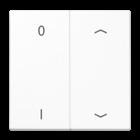

Ref.-no.
EnOcean radio transmitter with symbols 0 I
Thermoplastic (breakproof) high-gloss
EnOcean radio transmitter with symbols ▲▼
Thermoplastic (breakproof) high-gloss
EnOcean radio transmitter with symbols 0 I and ▲▼ Thermoplastic (breakproof) high-gloss
Adhesive film for radio transmitter (Spare part)

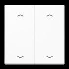
• Adhesive fixing in indoor areas on window panes, walls or furniture
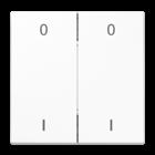
Modular system in which inserts and covers can be combined depending on the required function. Simple connector system for cover and insert and plenty of room for wiring to enable fast working.
Only individual modules from existing light and blind management installations can also be replaced by new ones from LB management and “old and new” used together.
At the site, test operation is possible using the test button without the cover. It is also used to set various operating modes. This optimises commissioning even more.
With this app, the Bluetooth devices of the LB Management are set and operated using a smartphone: Convenient control of the functions, displays of values and states, creation of time controls, and configuration.
Light, shading and temperature control in one system and one design. From switching and dimming to comfortable temperature: always easy to operate due to identical covers.
Manually using control buttons with clear symbols for identification of functions. By Bluetooth from a smartphone. Automatically using a timer switch, presence detector or automatic switch. Always intuitive.
With Bluetooth Low Energy, connecting and data transmission are particularly convenient. Therefore, this technology is used for LB Management – not just for configuration but also for operation. Independent of WLAN and networks.
In existing light or blind management installations, the components can be easily replaced by a specialist tradesman or further modules seamlessly added. Inexpensive, without great effort.
JUNG LB Management is the new system for modern lighting and automatic shading control. Using the combination of various inserts and covers, the modular system provides a needs-based and easy to use solution for almost every desired function. When retrofitting existing installations, individual components (always insert plus cover) can also be replaced by new devices from LB Management and the others can continue to be used.
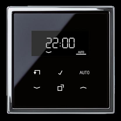
The standard centre plate is a 1-channel attachment for all LB Management inserts. Operation of light and shade is manual. The button can be actuated at the top, bottom and also full surface. The attachment is available with or without symbols.
The universal centre plate with memory and lock function is suitable for almost all LB Management inserts. A coloured LED is assigned to each rocker half and is used for the function or status display. Operation is performed manually or automatically. The cover for the automatic shading control is available with appropriate arrow symbols.


The blinds centre plate with timer function “standard” is a 1-channel timer for all inserts. The high-quality, real glass surface has an illuminated display and six sensor buttons for operation. The current time can be saved as the switching time using fast programming. The lock function deactivates automatic functions, satellites and timer programmes. Thanks to the Astro function, switching times are adapted to the position of the sun.


The blinds centre plate with timer function “universal” is an attachment for all inserts for lighting and automatic shading control. It is operated either manually with the two rockers or with a smartphone using the Clever Config app. Colour LEDs for function display and the appropriate button imprints optimise use.
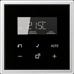
With the room thermostat, JUNG integrates the temperature control in LB Management. The new thermostat is identical to the standard timer with display in both design and operating concept. The temperature can thus be controlled as effortlessly as lighting or blinds.
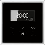
From simple switching to dimming energy saving lamps or Tunable White control, the light inserts provide all possibilities. Possible as a master unit just as much as a satellite unit.
All requirements for modern automatic shading control are covered with the two blind inserts “Standard” and “Universal” in combination with the LB Management covers.

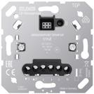
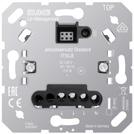
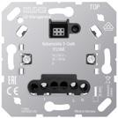
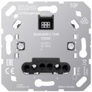
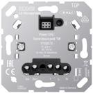
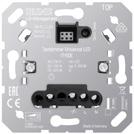

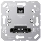
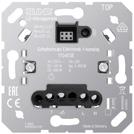
The room thermostat has time programs available and can if required be used for heating or cooling.
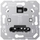 Relay switch insert 1-channel Electronic switch insert 1-channel Pulse insert
Standard touch dimmer insert LED
Universal touch dimmer insert LED
Power DALI push-button controller TW Satellite insert 2-wire Satellite insert 3-wire
Standard blinds insert Universal blinds insert Room thermostat insert
Standard blinds insert without satellite input for covers ref.-no.: .. 1700 .., .. 1701 .., .. 1750 D .., .. 1751 BT ..
Intended use
• Controlling electrically driven blinds, shutters and awnings

• Automatic time control via cover
• Operation with suitable cover of the LB Management
• Installation in flush box according to EN 60670-1
Product characteristics
• Automatic control via timer
• Test operation for functional test
• Pole changing of outputs for simplified commissioning from version V01 upwards
• Saving of a ventilation position possible using the cover
Technical data
Rated voltage: AC 230 V ~
Mains frequency: 50/60 Hz
Ambient temperature: −5 ... +45 °C
Contact type: µ
Stand-by power: max. 0.5 W
Running time: approx. 120 s
Connected load
Motors: 700 W
Connection
Connection mode: screw terminals single wire: 1 x 0.5 ... 4.0 mm2
2 x 0.5 ... 2.5 mm2
stranded without ferrule: 1 x 0.5 ... 4.0 mm2
2 x 0.5 ... 2.5 mm2
stranded with ferrule: 1 x 0.5 ... 4.0 mm2
2 x 0.5 ... 1.5 mm2
Universal blinds insert with satellite input for covers ref.-no.: .. 1700 .., .. 1701 .., .. 1750 D .., .. 1751 BT ..
Intended use
• Controlling electrically driven blinds, shutters and awnings
• Automatic time control via cover or satellite input
• Operation with suitable cover of the LB Management
• Installation in flush box according to EN 60670-1
Product characteristics
• The integration into group controls or master controls is possible by means of extension inputs
• Automatic control via timer
• Test operation for functional test
• Operation as a main device or extension unit
• Wind alarm interlock via the extension input

• Pole changing of outputs for simplified commissioning from version V01 upwards
• Saving of a ventilation position possible using the cover
Technical data
Rated voltage: AC 230 V ~
Mains frequency: 50/60 Hz
Ambient temperature: −5 ... +45 °C
Contact type: µ
Stand-by power: max. 0.2 W
Running time: approx. 120 s
Connected load
Motors: 700 W
Connection
Connection mode: screw terminals single wire: 1 x 0.5 ... 4.0 mm2
2 x 0.5 ... 2.5 mm2
stranded without ferrule: 1 x 0.5 ... 4.0 mm2
2 x 0.5 ... 2.5 mm2
stranded with ferrule: 1 x 0.5 ... 4.0 mm2
2 x 0.5 ... 1.5 mm2
Decoupling relays, weather station and awning control: starting from page 290
Standard touch dimmer insert LED without satellite input for covers ref.-no.: .. 1700 .., .. 1701 .., .. 1750 D .., .. 1751 BT .., .. 17180 .., .. 17280 .., .. 17181 .., .. 17281 .., DWPM 17360 ..
Intended use
• Switching and dimming of lighting
• Operation with suitable cover of the LB Management
• Installation in flush box according to EN 60670-1
Product characteristics
1710 DE
• Device works according to the leading edge phase control or trailing edge phase control principle
• Automatic or manual setting of the dimming principle suitable for the load
• Display of the set operating mode by means of LED
• Device can be operated without neutral conductor
• Switch-on via bulb-preserving soft start
• Switch-on with last brightness or saved switch-on brightness
• Switch-on brightness can be saved permanently
• Minimum brightness can be saved permanently
• Electronic short-circuit protection with permanent switch-off after 7 seconds at the latest
• Electronic over-temperature protection

• Test operation for functional test
• Power extension possible by means of power boosters (ref.-no. ULZ 1755 REG)
• Optional accessory: compensation module LED, ref.-no.: KM LED 230 U

Technical data
Rated voltage: AC 230 V ~
Mains frequency: 50/60 Hz
Power loss: approx. 2 W
Ambient temperature: −5 ... +45 °C
Connected load at 25 °C
Incandescent lamps: 20 ... 210 W
HV halogen lamps: 20 ... 210 W
Electronic transformers: 20 ... 210 W
Electronic transformers with LV LED: typical 20 ... 60 W
Inductive transformers: 20 ... 210 VA
Inductive transformers with LV LED: typical 20 ... 60 VA
Dimmable HV LED lamps: typical 3 ... 60 W
Dimmable compact fluorescent lamps: typical 3 ... 60 W
With setting "LED trailing edge phase control" the max. connection power for HV LED lamps and electronic transformers with LV LED doubles.
Ohmic-capacitive: 20 ... 210 W
Capacitive-inductive: not permitted
Ohmic-inductive: 20 ... 210 VA
Ohmic and HV LED: typical 3 ... 60 W
Ohmic and CFL: typical 3 ... 60 W
Amplifiers: see instructions for amplifier
Connection: screw terminals
single wire:
1 x 0.5 ... 4.0 mm2
2 x 0.5 ... 2.5 mm2
stranded without ferrule: 1 x 0.5 ... 4.0 mm2
2 x 0.5 ... 2.5 mm2
stranded with ferrule: 1 x 0.5 ... 4.0 mm2
2 x 0.5 ... 1.5 mm2
Total length power cable: max. 100 m
Ref.-no.
Universal touch dimmer insert LED with satellite input for covers ref.-no.: .. 1700 .., .. 1701 .., .. 1750 D .., .. 1751 BT .., .. 17180 .., .. 17280 .., .. 17181 .., .. 17281 .., DWPM 17360 ..
Intended use
• Switching and dimming of lighting • Operation with suitable cover of the LB Management • Installation in flush box according to EN 60670-1
Product characteristics
• Device works according to the leading edge phase control or trailing edge phase control principle • Automatic or manual setting of the dimming principle suitable for the load • Display of the set operating mode by means of LED • Device can be operated without neutral conductor • Switch-on via bulb-preserving soft start
• Switch-on with last brightness or saved switch-on brightness

• Minimum brightness can be saved permanently
• Connection of satellite units possible
• Switch-on brightness can be saved permanently
• Electronic short-circuit protection with permanent switch-off after 7 seconds at the latest • Electronic overtemperature protection • Test operation for functional test • Key card function • Power extension possible by means of power boosters (ref.-no. ULZ 1755 REG) • Optional accessory: compensation module LED, ref.-no.: KM LED 230 U
Technical data
Rated voltage: AC 230 V ~
Mains frequency: 50/60 Hz
Stand-by power depending on the cover: approx. 0.1 ... 0.5 W
Power loss: approx. 4 W
Ambient temperature: −5 ... +45 °C
Connected load at 25 °C
Incandescent lamps: 20 ... 420 W
HV halogen lamps: 20 ... 420 W
Electronic transformers: 20 ... 420 W
Electronic transformers with LV LED: typical 20 ... 100 W
Inductive transformers: 20 ... 420 VA
Inductive transformers with LV LED: typical 20 ... 100 VA
Dimmable HV LED lamps: typical 3 ... 100 W
Dimmable compact
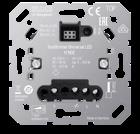
fluorescent lamps: typical 3 ... 100 W
Operating mode LED trailing edge phase control: Rated power for HV LED lamps, typ. 3 ... 400 W, electronic transformers with LV LED typ. 20 ... 200 W.
Ohmic-capacitive: 20 ... 420 W
Capacitive-inductive: not permitted
Ohmic-inductive: 20 ... 420 VA
Ohmic and HV LED: typical 3 ... 100 W
Ohmic and CFL: typical 3 ... 100 W
Amplifiers: see instructions for amplifier
Connection: screw terminals
single wire:
stranded without ferrule:
stranded with ferrule:
Number of satellite units
1 x 0.5 ... 4.0 mm2
2 x 0.5 ... 2.5 mm2
1 x 0.5 ... 4.0 mm2
2 x 0.5 ... 2.5 mm2
1 x 0.5 ... 4.0 mm2
2 x 0.5 ... 1.5 mm2
Satellite insert 2-wire 1720 NE: unlimited
Satellite insert 3-wire 1723 NE: 10
Rotary satellite insert 3-wire 1733 DNE: 10
Push-buttons: unlimited
Total length of extension unit cable: max. 100 m
Total length power cable: max. 100 m
Universal 2-gang touch dimmer insert LED with satellite input for covers ref.-no.: .. 1702 ..
Intended use
• Switching and dimming of lighting
• Operation with suitable cover of the LB Management
• Installation in flush box according to EN 60670-1
Product characteristics
• Two independent outputs for two light groups • Asymmetric load distribution possible • Device works according to the leading edge phase control or trailing edge phase control principle • Automatic or manual setting of the dimming principle suitable for the load • Display of the set operating mode by means of LED • Device can be operated without neutral conductor • Switch-on via bulb-preserving soft start • Switch-on with last brightness or saved switch-on brightness • Switch-on brightness can be saved permanently • Minimum brightness can be saved permanently • Connection of satellite units possible • Electronic short-circuit protection with permanent switch-off after 7 seconds at the latest • Electronic over-temperature protection
• Test operation for functional test • Power extension possible by means of power boosters (ref.-no. ULZ 1755 REG) • Optional accessory: compensation module LED, ref.-no.: KM LED 230 U
Technical data
Rated voltage:
AC 230 V ~
Mains frequency: 50/60 Hz
Stand-by power depending on the cover: approx. 0.1 ... 0.5 W
Power loss: approx. 4 W
Ambient temperature: −5 ... +45 °C
Connected load per output at 25 °C
Incandescent lamps: 20 ... 210 W
HV halogen lamps: 20 ... 210 W
Electronic transformers: 20 ... 210 W
Electronic transformers with LV LED: typical 20 ... 50 W
Inductive transformers: 20 ... 210 VA
Inductive transformers with LV LED: typical 20 ... 50 VA
Dimmable HV LED lamps: typical 3 ... 50 W
Dimmable compact fluorescent lamps: typical 3 ... 50 W
With setting "LED trailing edge phase control" the max. connection power for HV LED lamps and electronic transformers with LV LED doubles.
Ohmic-capacitive: 20 ... 210 W
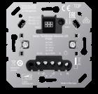

Capacitive-inductive: not permitted
Ohmic-inductive: 20 ... 210 VA
Ohmic and HV LED: typical 3 ... 50 W
Ohmic and CFL: typical 3 ... 50 W
Amplifiers: see instructions for amplifier
Connection: screw terminals
single wire:
stranded without ferrule:
stranded with ferrule:
Number of satellite units
1 x 0.5 ... 4.0 mm2
2 x 0.5 ... 2.5 mm2
1 x 0.5 ... 4.0 mm2
2 x 0.5 ... 2.5 mm2
1 x 0.5 ... 4.0 mm2
2 x 0.5 ... 1.5 mm2
Satellite insert 2-wire 1720 NE: unlimited
Satellite insert 3-wire 1723 NE: 10
Rotary satellite insert 3-wire 1733 DNE: 10
Push-buttons: unlimited
Total length of extension unit cable: max. 100 m
Total length power cable: max. 100 m
Ref.-no.
Power DALI push-button controller TW with satellite input for covers ref.-no.: .. 1700 .., .. 1701 .., .. 1702 .., .. 1750 D .., .. 1751 BT .., .. 17180 .., .. 17280 .., .. 17181 .., .. 17281 .., DWPM 17360 ..
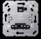
Intended use
• Switching and brightness setting for luminaires with DALI interface
• Setting of colour temperature for luminaires with DALI Device Type 8 for tunable white acc. to IEC 62386-209
• Operation with suitable cover of the LB Management
• If several automatic switches are to be used, a DALI push-button controller can be connected to up to five 3-wire satellite inserts. Parallel connection of several DALI push-button controllers with automatic switches or motion/presence detectors is not possible.
• Installation in flush box according to EN 60670-1
Product characteristics
• DALI supply for a maximum of 18 subscribers
• Parallel switching of up to 4 DALI control units with the option of supplying up to 72 DALI subscribers
• Saving of minimum brightness, coldest and warmest colour temperature
• Switch-on with last brightness / colour temperature or saved switch-on brightness / colour temperature

• With centre plate 2-gang: Adjustment of the colour temperature via right rocker
• Test operation for functional test
Technical data
Rated voltage: AC 230 V ~
Mains frequency: 50/60 Hz
Power consumption: max. 2.8 W
Ambient temperature: −5 ... +45 °C
Rated voltage DALI: DC 16 V
Output current: max. 36 mA
Short-circuit current: max. 60 mA
Colour temperature setting: 2,000 ... 10,000 K
Number of DALI devices: max. 18
Number of control units in parallel: max. 4
Connection: screw terminals
single wire:
1 x 0.5 ... 4.0 mm2
2 x 0.5 ... 2.5 mm2
stranded without ferrule: 1 x 0.5 ... 4.0 mm2
2 x 0.5 ... 2.5 mm2
stranded with ferrule: 1 x 0.5 ... 4.0 mm2
2 x 0.5 ... 1.5 mm2
Relay switch insert 1-channel with satellite input for covers ref.-no.: .. 1700 .., .. 1701 .., .. 1750 D .., .. 1751 BT .., .. 17180 .., .. 17280 .., .. 17181 .., .. 17281 .., DWPM 17360 .. for displays ref.-no.: .. 1790 D ..
Intended use
• Switching of lighting and motors
• Operation with suitable cover of the LB Management
• Controlling of electric underfloor heating systems and electrothermal valve drives in combination with a room thermostat cover
• Installation in flush box according to EN 60670-1
Product characteristics
• Connection of satellite units possible
• Run-on times adjustable
• Test operation for functional test
• Adaptive zero-point switching

Technical data
Rated voltage: AC 230 V ~ Mains frequency: 50/60 Hz
Stand-by power depending on the cover: approx. 0.1 ... 0.5 W
Switching current at 35 °C
Ohmic: 16 A (AC1)
Connected load
Incandescent lamps: 2300 W
HV halogen lamps: 2300 W
Electronic transformers: 1500 W
Inductive transformers: 1000 VA
HV LED lamps: typical 400 W
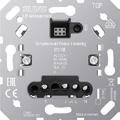
Compact fluorescent lamps: typical 500 W
Fluorescent lamps
non-compensated: 1200 VA
Motor switching current: 6 A
Capacitive load: 920 VA (115 µF)
Connection: screw terminals
single wire: 1 x 0.5 ... 4.0 mm2
2 x 0.5 ... 2.5 mm2
stranded without ferrule: 1 x 0.5 ... 4.0 mm2
2 x 0.5 ... 2.5 mm2
stranded with ferrule: 1 x 0.5 ... 4.0 mm2
2 x 0.5 ... 1.5 mm2
Ambient temperature: −25 ... +45 °C
Storage/transport temperature: −20 ... +70 °C
Number of satellite units
Satellite insert 2-wire 1720 NE: unlimited
Satellite insert 3-wire 1723 NE: 10
Push-buttons: unlimited
Shut-off delay: without, 1 min, 5 min, 30 min, 60 min
1701 SE
Ref.-no.
Relay switch insert 2-channel with satellite input for covers ref.-no.: .. 1700 .., .. 1701 .., .. 1702 .., .. 1750 D .., .. 1751 BT .., .. 17180 .., .. 17280 .., .. 17181 .., .. 17281 .., DWPM 17360 ..
Intended use
• Switching of lighting and motors • Operation with suitable cover of the LB Management • Installation in flush box according to EN 60670-1
Product characteristics
• Connection of satellite units possible
• Test operation for functional test
In combination with centre plate 2-gang:
• Two independent outputs
• Time function for output a2 adjustable
In combination with centre plate (ref.-no. ..1700.., ..1701..), timer, automatic switch:
Technical data
Rated voltage:
• Output a2 switches depending on output a1 e.g. to switch on ventilation, depending on the lighting, and switch it off with a delay.
• Switch-on delay of output a2 adjustable
• Run-on time of output a2 adjustable
In combination with satellite insert 3-wire and centre plate 2-gang:
• Two independent outputs
In combination with satellite insert 2-wire, rotary satellite insert or push-button:
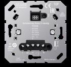
• Output a2 switches depending on output a1 e.g. to switch on ventilation, depending on the lighting, and switch it off with a delay.
AC 230 V ~
Mains frequency: 50/60 Hz
Stand-by power depending on the cover: approx. 0.1 ... 0.5 W
Ambient temperature:

−25 ... +45 °C
Storage/transport temperature: −20 ... +70 °C
Switching current per device:
Switching current per channel for 25 °C
Σ 16 A
Ohmic: 10 A (AC1)
Motors: 3 A (cos ϕ = 0.68)
Connected load per channel for 25 °C
Incandescent lamps: 1500 W
HV halogen lamps: 1500 W
Electronic transformers: 1000 W
Inductive transformers: 625 VA
HV LED lamps: typical 500 W
Compact fluorescent lamps: typical 500 W
Fluorescent lamps non-compensated: 750 VA
Capacitive load: 580 VA (70 µF)
Connection: screw terminals
single wire:
stranded without ferrule:
stranded with ferrule:
Number of satellite units
1 x 0.5 ... 4.0 mm2
2 x 0.5 ... 2.5 mm2
1 x 0.5 ... 4.0 mm2
2 x 0.5 ... 2.5 mm2
1 x 0.5 ... 4.0 mm2
2 x 0.5 ... 1.5 mm2
Satellite insert 2-wire 1720 NE: unlimited
Satellite insert 3-wire 1723 NE: 10
Rotary satellite insert 3-wire 1733 DNE: 10
Push-buttons: unlimited
Shut-off delay: without, 1 min, 5 min, 30 min, 60 min
Switch-on delay: without, 3 min
Electronic switch insert 1-channel with satellite input for covers ref.-no.: .. 1700 .., .. 1701 .., .. 1750 D .., .. 1751 BT .., .. 17180 .., .. 17280 .., .. 17181 .., .. 17281 .., DWPM 17360 .. for displays ref.-no.: .. 1790 D ..
Intended use
• Operation with suitable cover of the LB Management
• Installation in flush box according to EN 60670-1
Operation with neutral conductor:
• Switching of incandescent lamps, HV halogen lamps, electronic or inductive transformers with halogen or LED lamps, switchable or dimmable HV-LED or compact fluorescent lamps
Operation without neutral conductor:
• Switching of incandescent lamps, HV halogen lamps, electronic or inductive transformers with halogen or LED lamps, dimmable HV-LED or compact fluorescent lamps
Product characteristics
• Switch-on via bulb-preserving soft start
• Connection of satellite units possible
• Electronic short-circuit protection with permanent switch-off after 7 seconds at the latest
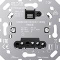
• Electronic over-temperature protection

• Test operation for functional test
Operation with neutral conductor:
• Device is powered via phase conductor and neutral conductor , therefore there is no leading edge phase control or trailing edge phase control
Operation without neutral conductor:
• Device is powered via the phase conductor and the connected load and therefore works in the leading edge phase control or trailing edge phase control principle
• Automatic or manual setting of the operating mode suitable for the load
• Display of the set operating mode by means of LED
Technical data
Rated voltage: AC 230 V ~
Mains frequency: 50/60 Hz
Stand-by power: approx. 0.25 W
Power loss: approx. 4 W
Ambient temperature: −5 ... +45 °C
Connected load at 25 °C
Incandescent lamps: 20 ... 400 W
HV halogen lamps: 20 ... 400 W
Electronic transformers: 20 ... 400 W
Electronic transformers with LV LED: 20 ... 100 W
Inductive transformers: 20 ... 400 VA
Inductive transformers with LV LED: 20 ... 100 VA

HV LED lamps: typical 3 ... 100 W
Compact fluorescent lamps: typical 3 ... 100 W
When operating with neutral conductor or without neutral conductor in operating mode LED trailing edge phase control: Connection power for HV LED lamps typ. 3 ... 200 W, electronic transformers with LV LED typ. 20 ... 200 W.
Ohmic-capacitive: 20 ... 400 W
Capacitive-inductive: not permitted
Ohmic-inductive: 20 ... 400 VA
Ohmic and HV LED: typical 3 ... 100 W
Ohmic and CFL: typical 3 ... 100 W
Operation without neutral conductor in operating mode R,L,C,LED:
Ohmic-inductive mixed load: maximum 50 % proportion of ohmic load.
Otherwise incorrect calibration of the dimmer may result.
Operation without neutral conductor: Minimum load 50 W.
Does not apply to loads with HV LED and compact fluorescent lamps.
When using LED lamps that are not dimmable the neutral conductor must be connected.
Connection: screw terminals
single wire:
stranded without ferrule:
stranded with ferrule:
Number of satellite units
1 x 0.5 ... 4.0 mm2
2 x 0.5 ... 2.5 mm2
1 x 0.5 ... 4.0 mm2
2 x 0.5 ... 2.5 mm2
1 x 0.5 ... 4.0 mm2
2 x 0.5 ... 1.5 mm2
Satellite insert 2-wire 1720 NE: unlimited
Satellite insert 3-wire 1723 NE: 5
Push-buttons: unlimited
Total length of extension unit cable: max. 100 m
Total length power cable: max. 100 m
Satellite insert 2-wire for covers ref.-no.: .. 1700 ..
Intended use
• Extension unit operation of suitable inserts of the LB Management
• Operation with standard centre plate
• Installation in flush box according to EN 60670-1
Technical data
Rated voltage: AC 230 V ~ Mains frequency: 50/60 Hz
Ambient temperature: −20 ... +45 °C
Connection: screw terminals single wire: 1 x 0.5 ... 4.0 mm2
2 x 0.5 ... 2.5 mm2
stranded without ferrule: 1 x 0.5 ... 4.0 mm2
2 x 0.5 ... 2.5 mm2
stranded with ferrule: 1 x 0.5 ... 4.0 mm2
2 x 0.5 ... 1.5 mm2
Total length of extension unit cable: max. 100 m
Satellite insert 3-wire for covers ref.-no.: .. 1700 .., .. 1701 .., .. 1702 .., .. 1750 D .., .. 1751 BT .., .. 17180 .., .. 17280 .., .. 17181 .., .. 17281 .., DWPM 17360 ..
Intended use
• Extension unit operation of suitable inserts of the LB Management
• Satellite for extending the detection field of motion and presence detectors
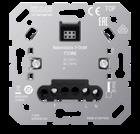
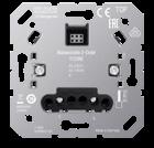

• Central control of multiple main devices
• Operation with suitable cover of the LB Management
• Installation in flush box according to EN 60670-1
• Neutral conductor required
Technical data
Rated voltage: AC 230 V ~ Mains frequency: 50/60 Hz
Ambient temperature: −20 ... +45 °C
Connection: screw terminals single wire: 1 x 0.5 ... 4.0 mm2
2 x 0.5 ... 2.5 mm2
stranded without ferrule: 1 x 0.5 ... 4.0 mm2
2 x 0.5 ... 2.5 mm2
stranded with ferrule: 1 x 0.5 ... 4.0 mm2
2 x 0.5 ... 1.5 mm2
Total length of extension unit cable: max. 100 m
1720 NE
Pulse insert for covers ref.-no.: .. 1700 .., .. 1700 P .., .. 17180 .., .. 17280 .., .. 17181 .., .. 17281 .., DWPM 17360 ..
Intended use
• Manual or automatic control of the power unit ref-no. 1208 REG

• Operation with suitable cover of the LB Management
• Installation in flush box according to EN 60670-1
Product characteristics
1708
• Manual switching in combination with standard centre plate ref.-no.: .. 1700 .., .. 1700 P
• Automatic switching in combination with motion detectors of the LB Management

• Operation in 3- or 4-conductor circuit
• Insert designed with 2-wire technology
Technical data
Rated voltage: AC 230 V ~
Mains frequency: 50 Hz
Power consumption: 0.25 ... 0.45 W
Current consumption: approx. 2.8 mA
Ambient temperature: −5 ... +45 °C
Pulse duration: approx. 60 ms
Pulse interval: approx. 8 s
Connection: screw terminals single wire: 1 x 0.5 ... 4.0 mm2
2 x 0.5 ... 2.5 mm2
stranded without ferrule: 1 x 0.5 ... 4.0 mm2
2 x 0.5 ... 2.5 mm2
stranded with ferrule: 1 x 0.5 ... 4.0 mm2
2 x 0.5 ... 1.5 mm2
Intended use
• Manual or automatic switching of light in stairways
• Installation in distribution boxes on DIN rail according to EN 60715
• Switch-on via pulse insert or push-button
Product characteristics
• Run-on time adjustable
• Electronic overload protection for the control input
Four different operating modes can be set:
• Automatic function without switch-off warning
• Automatic function with switch-off warning
• Light switched ON continuously
• Light switched OFF continuously
Automatic switching of light
The pulse insert is combined with a motion detector cover. As soon as the brightness drops below a value set on the motion detector cover and motions are detected, the pulse insert sends a switch-on signal cyclically to the automatic RMD. The latter switches on the light for the set run-on time. After the run-on time has elapsed, the automatic RMD switches the light off. After switch-off, pulse inserts with motion detector covers will not detect any motions for approx. 3 seconds.
Technical data
Rated voltage: AC 230 V ~
Mains frequency: 50 Hz
Power consumption: approx. 1 W
Ambient temperature: +5 ... +45 °C
Shut-off delay: approx. 10 s ... 15 min
Shut-off delay tolerance: ± 20 %
Permissible current for control input A1: max. 40 mA
Switching voltage: AC 250 V ~
Switching current
Ohmic: 16 A
Switch-on current 20 ms: max. 165 A
Connected load
Incandescent lamps: 2300 W
HV halogen lamps: 2300 W
HV LED lamps: 400 W
Fluorescent lamps
parallel compensated: 920 W
Fluorescent lamps
non-compensated: 1200 VA
Fluorescent lamps lead-lag circuit: 2300 W / 140 µF
Electronic transformers: 1500 W
Inductive transformers: 1000 VA
Electronic ballast: depending on type

Mounting width: 18 mm (1 rail unit)
Total length power cable: max. 100 m
Total length of control cable: max. 100 m
Connection: screw terminals
single wire: 1 x 0.75 ... 4.0 mm2
2 x 0.75 ... 2.5 mm2
stranded without ferrule: 1 x 0.75 ... 4.0 mm2
2 x 0.75 ... 2.5 mm2
stranded with ferrule: 1 x 0.5 ... 2.5 mm2
Ref.-no.
Room thermostat insert with sensor connection for displays ref.-no.: .. 1790 D ..
Intended use
• Switching of electric underfloor heating systems and electrothermal valve drives
• Operation with room temperature controller cover of the LB Management
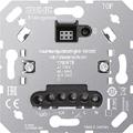
• Installation in flush box according to EN 60670-1
Product characteristics
• Pulse width modulation (PWM) or two-point control (on/off)
• Enables connection of a remote sensor (ref.-no.: FF 7.8)
• Input for switching to cooling mode
• Interrupts the heating process after 60 minutes (overheating protection of a heater)
Technical data
Rated voltage:
AC 230 V ~
Mains frequency: 50/60 Hz
Stand-by power depending on the cover: approx. 0.1 ... 0.5 W
Switching current 230 V AC1: 10 mA ... 16 A
Connected load: max. 3,600 W
Connection
single wire:
1 x 0.5 ... 4.0 mm2
2 x 0.5 ... 2.5 mm2
stranded without ferrule: 1 x 0.5 ... 4.0 mm2
stranded with ferrule:
2 x 0.5 ... 2.5 mm2
1 x 0.5 ... 4.0 mm2
2 x 0.5 ... 1.5 mm2
Ambient temperature: −5 ... +45 °C
Displays standard for room temperature control see page 264

External temperature sensor for room thermostat ref.-no. 1790 RTR, TR D .. 1790 .. spare part for floor thermostat ref.-no. FTR .. 231 .. The sensor cable can be connected using a bifilar cable of 1.5 mm2 in diameter that is suitable for mains voltage. When installed in a cable duct or near high voltage current cables, a shielded cable must be used.
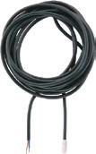
FF 7.8
Also suitable as external temperature sensor for the following KNX devices, ref.-no.: .. 2178 TS .., .. 2178 ORTS .., .. 5192 KRM TS D, .. 5194 KRM TS D, 2177 SV R, 23066 REGHE
Technical data
NTC sensor in plastic cap 7.8 mm Ø
Cable length: 4 m
Ambient temperature: −25 ... +70 °C
Standard centre plate for LB Management inserts "blinds" ref.-no.: 1730 JE and 1731 JE for LB Management inserts "light" ref.-no.: 1701 SE, 1704 ESE, 1702 SE, 1710 DE, 1711 DE, 1713 DSTE, 1720 NE, 1723 NE, 1708 IE Intended use
• Manual operation of Venetian blinds, shutters, awnings or lighting
• Operation with blinds, switch, dimmer, pulse or satellite insert of the LB Management

Product characteristics
• Activation of blinds/shutters, with blinds insert
• Switching and dimming of lighting, with switch / dimmer or pulse insert


• Ventilation position of the blind/shutter can be saved, with blinds insert
• Switch-on brightness of lighting can be saved, with dimmer insert and DALI push-button controller
for AS range
Duroplastic (scratch-proof) glossy
for A range
glossy
high-gloss
Duroplastic


for LS range

Standard centre plate "arrows" for LB Management inserts "blinds" ref.-no.: 1730 JE and 1731 JE for LB Management inserts "light" ref.-no.: 1701 SE, 1704 ESE, 1702 SE, 1710 DE, 1711 DE, 1713 DSTE, 1720 NE, 1723 NE, 1708 IE Intended use
• Manual operation of Venetian blinds, shutters, awnings or lighting
• Operation with blinds, switch, dimmer, pulse or satellite insert of the LB Management

Product characteristics
• Activation of blinds/shutters, with blinds insert
• Switching and dimming of lighting, with switch / dimmer or pulse insert
• Ventilation position of the blind/shutter can be saved, with blinds insert
• Switch-on brightness of lighting can be saved, with dimmer insert and DALI push-button controller
for AS range
Duroplastic (scratch-proof) glossy
for A range
glossy
(breakproof) high-gloss
Standard
plate "arrows" for CD range



Duroplastic
for LS range
Duroplastic
Universal centre plate for LB Management inserts "blinds" ref.-no.: 1730 JE and 1731 JE for LB Management inserts "light" ref.-no.: 1701 SE, 1704 ESE, 1702 SE, 1710 DE, 1711 DE, 1713 DSTE, 1723 NE
Intended use
• Manual and time-controlled operation of Venetian blinds, shutters, awnings or lighting
• Operation with switch, dimmer or blinds insert or satellite insert 3-wire of the LB Management

Product characteristics
• Activation of blinds/shutters, with blinds insert
• Switching and dimming of lighting, with switch or dimmer insert
• Ventilation position of the blind/shutter can be saved, with blinds insert
• Switch-on brightness of lighting can be saved, with dimmer insert and DALI push-button controller


• Disabling function
• 2 switching times can be saved, which are repeated in a 24-hour cycle
for AS range
Duroplastic (scratch-proof) glossy
for A range
Universal centre plate for CD range
Duroplastic (scratch-proof) glossy
ivory CD 1701
white
brown
grey
light grey
CD 1701 WW
CD 1701 BR
CD 1701 GR
CD 1701 LG

black CD 1701 SW
metal colours (duroplastic lacquered)
gold-bronze CD 1701 GB
platinum CD 1701 PT
for LS range
Duroplastic (scratch-proof) glossy
ivory LS 1701
white LS 1701 WW
light grey LS 1701 LG
black LS 1701 SW
matt lacquered
matt snow white LS 1701 WWM
matt graphite black LS 1701 SWM metal versions
aluminium
stainless steel
anthracite (aluminium lacquered) AL 1701 AN
dark (aluminium lacquered)
chrome
gold-coloured
classic brass
antique brass
Universal centre plate "arrows" for LB Management inserts "blinds" ref.-no.: 1730 JE and 1731 JE for LB Management inserts "light" ref.-no.: 1701 SE, 1704 ESE, 1702 SE, 1710 DE, 1711 DE, 1713 DSTE, 1723 NE
Intended use
• Manual and time-controlled operation of Venetian blinds, shutters, awnings or lighting
• Operation with switch, dimmer or blinds insert or satellite insert 3-wire of the LB Management

Product characteristics
• Activation of blinds/shutters, with blinds insert
• Switching and dimming of lighting, with switch or dimmer insert
• Ventilation position of the blind/shutter can be saved, with blinds insert
• Switch-on brightness of lighting can be saved, with dimmer insert and DALI push-button controller

• Disabling function
• 2 switching times can be saved, which are repeated in a 24-hour cycle
for AS range Duroplastic (scratch-proof) glossy
A range
Universal centre plate "arrows" for CD range


Duroplastic (scratch-proof) glossy
Duroplastic
Ref.-no.
Standard centre plate 2-gang for LB Management inserts "light" ref.-no.: 1702 SE, 1712 DE, 1713 DSTE, 1723 NE


Intended use
• Manual operation of lighting
• Operation with 2-channel switch or dimmer insert, DALI push-button controller or satellite insert 3-wire of the LB Management
Product characteristics
• Switching, dimming and colour temperature setting of lighting, with switch or dimmer insert

• Full control of switch and dimmer inserts, with satellite insert 3-wire
• Switch-on brightness of lighting can be saved, with dimmer insert and DALI push-button controller
• Colour temperature can be saved, with DALI push-button controller
for AS range
Duroplastic (scratch-proof) glossy
A range
glossy
Standard centre plate 2-gang for CD range

Duroplastic (scratch-proof) glossy
ivory CD 1702
white
brown
grey
light grey
black
metal colours (duroplastic lacquered)
CD 1702 WW
CD 1702 BR
CD 1702 GR
CD 1702 LG
CD 1702 SW

gold-bronze CD 1702 GB
platinum
for LS range
Duroplastic (scratch-proof) glossy
CD 1702 PT
ivory LS 1702
white

light grey
black
matt lacquered
matt snow white
matt graphite black
aluminium
stainless
anthracite (aluminium lacquered) AL 1702 AN
dark (aluminium lacquered)
classic brass
antique brass
eNet radio centre plates, see chapter eNet, page 172
Standard timer with display for LB Management inserts "blinds" ref.-no.: 1730 JE and 1731 JE for LB Management inserts "light" ref.-no.: 1701 SE, 1704 ESE, 1702 SE, 1710 DE, 1711 DE, 1713 DSTE, 1723 NE
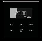
Intended use
• Manual and time-controlled operation of Venetian blinds, shutters, awnings or lighting
• Operation with switch, dimmer or blinds insert or satellite insert 3-wire of the LB Management
Product characteristics
• Real glass front panel
• 6 sensor buttons
• Current time can be saved as switching time, quick programming
• Automatic summer/winter time changeover, can be switched off

• Switching at sunrise and/or before sunset (astro function) adjustable for 18 countries
• Astro time shift for sunrise and sunset
• Disabling function
• Display switches off after 2 minutes, permanent indication of the current time possible
• Activation of blinds/shutters, with blinds insert
• Programming of one up time and one down time each for the parts of the week Mo-Fr and Sa+Su
• Ventilation position of the blind/shutter can be saved, with blinds insert
• Switching and dimming of lighting, with switch or dimmer insert
• Programming of two memory areas with one switch-on and one switch-off time each for the parts of the week Mo-Fr and Sa+Su
• Switch-on brightness of lighting can be saved, with dimmer insert and DALI push-button controller
for AS and A ranges
CD range
LS range
The universal timer Bluetooth is primarily impressive due to its operating concept. Sun protection and light can be operated both mechanically by pressing a button as well on the move.
The configuration and control of the Bluetooth devices from LB Management, such as the timer, is particularly easy using the Clever Config app: Displays of values and states, creation of time controls and adjustment of parameters such as shut-off delay or brightness, and the control of the functions.
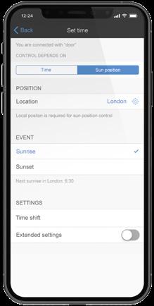

Universal timer Bluetooth for LB Management inserts "blinds" ref.-no.: 1730 JE and 1731 JE for LB Management inserts "light" ref.-no.: 1701 SE, 1704 ESE, 1702 SE, 1710 DE, 1711 DE, 1713 DSTE, 1723 NE
Intended use
• Manual and time-controlled operation of Venetian blinds, shutters, awnings, lighting or fans
• Operation and programming with smartphone in combination with Clever Config App via Bluetooth
• Operation with switch, dimmer or blinds insert or satellite insert 3-wire of the LB Management
Product characteristics
Functions directly via cover
• Operation of blinds/shutters and lighting
• Activating / deactivating the disabling function
• Activating / deactivating automatic operation
• Running time and ventilation position of the blind/shutter can be saved
• Switch-on brightness or switch on to last brightness (with dimming insert) can be saved
• Night mode
Functions via Clever Config App
• Operation of blinds/shutters and lighting with status feedback
• Display of current blind/shutter position, dimming position or switching state
• Programming of up to 40 individual switching times
• Blind and slat positions or switching and dimming values can be saved for each switching time
• Possible to copy switching times to other universal timers Bluetooth
• Switching at sunrise and/or before sunset (astro function)
• Astro time by means of geolocation
• Astro time shift can be set for each switching time
• Automatic summer/winter time changeover, can be switched off
• Random function
• Automatic date and time update when connecting with smartphone
• Code request for protection for time programs and configuration possible
• Save a ventilation position, blind/shutter running time, slat change-over time and change-over time for direction change
• Switch to inverse operation for Venetian blind inserts possible
• Maximum brightness and minimum brightness for dimming insert can be set
• Sun protection and twilight function possible via optional brightness / temperature sensor ref.-no.: 1792 HT BT

Technical data
Ambient temperature: −5 ... +45 °C
Storage/transport temperature: −20 ... +70 °C
Accuracy per month: ± 10 s
The time is updated with every connection to the app.
Power reserve: approx. 4 h
Radio frequency: 2.402 ... 2.480 GHz
Transmitting power: max. 2.5 mW (class 2)
Transmission range: typical 10 m


for AS range
Duroplastic (scratch-proof) glossy ivory
for A range
Duroplastic (scratch-proof) glossy white
black
Duroplastic
aluminium
mocha
Thermoplastic (breakproof) high-gloss
white
black
matt
matt
matt
for CD range
Duroplastic (scratch-proof) glossy ivory
brown
light
metal colours (duroplastic lacquered)
gold-bronze
platinum
for LS range
Duroplastic (scratch-proof) glossy
Universal timer Bluetooth "arrows" for LB Management inserts "blinds" ref.-no.: 1730 JE and 1731 JE for LB Management inserts "light" ref.-no.: 1701 SE, 1704 ESE, 1702 SE, 1710 DE, 1711 DE, 1713 DSTE, 1723 NE
Intended use
• Manual and time-controlled operation of Venetian blinds, shutters, awnings, lighting or fans
• Operation and programming with smartphone in combination with Clever Config App via Bluetooth
• Operation with switch, dimmer or blinds insert or satellite insert 3-wire of the LB Management
Product characteristics
Functions directly via cover
• Operation of blinds/shutters and lighting
• Activating / deactivating the disabling function
• Activating / deactivating automatic operation
• Running time and ventilation position of the blind/shutter can be saved
• Switch-on brightness or switch on to last brightness (with dimming insert) can be saved
• Night mode
Functions via Clever Config App
• Operation of blinds/shutters and lighting with status feedback
• Display of current blind/shutter position, dimming position or switching state
• Programming of up to 40 individual switching times
• Blind and slat positions or switching and dimming values can be saved for each switching time
• Possible to copy switching times to other universal timers Bluetooth
• Switching at sunrise and/or before sunset (astro function)
• Astro time by means of geolocation
• Astro time shift can be set for each switching time
• Automatic summer/winter time changeover, can be switched off
• Random function
• Automatic date and time update when connecting with smartphone
• Code request for protection for time programs and configuration possible
• Save a ventilation position, blind/shutter running time, slat change-over time and change-over time for direction change
• Switch to inverse operation for Venetian blind inserts possible
• Maximum brightness and minimum brightness for dimming insert can be set
• Sun protection and twilight function possible via optional brightness / temperature sensor ref.-no.: 1792 HT BT

Technical data
Ambient temperature: −5 ... +45 °C
Storage/transport temperature: −20 ... +70 °C
Accuracy per month: ± 10 s
The time is updated with every connection to the app.
Power reserve: approx. 4 h
Radio frequency: 2.402 ... 2.480 GHz
Transmitting power: max. 2.5 mW (class 2)
Transmission range: typical 10 m
Universal timer Bluetooth "arrows"


for AS range
Duroplastic
glossy
for A range
Duroplastic (scratch-proof) glossy
Thermoplastic (breakproof) high-gloss
for CD range
Duroplastic (scratch-proof) glossy
for LS range
Duroplastic
(duroplastic lacquered)
Intended use
• Sensor for detection of brightness and temperature
• Operation with universal timer Bluetooth of the LB Management
• Adhesive fixing in indoor areas on window panes, walls or furniture
Product characteristics
• Brightness and temperature measurement takes place once per minute

• Transmits the current brightness and temperature value every 5 minutes
• Transmits the brightness value if the brightness changes by more than 10 % of the last transmitted value

• Transmits the current temperature value if the temperature changes by more than 0.2 K
• Extended functions for Timer Bluetooth: sun protection function, dusk and dawn
• Indicates low battery level
• Battery-powered device
• Commissioning with Clever Config App
Rated voltage: DC 3 V
Battery type: 1 x lithium CR 2450 (included)
Brightness measurement: 5 ... 80,000 lx
Temperature measurement: −5 ... +55 °C
Ambient temperature: −5 ... +55 °C
Storage/transport temperature: −20 ... +70 °C
Dimensions (L x W x H): 56 x 32 x 13 mm
Radio frequency: 2.402 ... 2.480 GHz
Transmitting power: max. 2.5 mW (class 2)
Transmission range: typical 10 m
The 180° detection range of the automatic switches is monitored by two PIR sensors that can be used individually or together. In the function as movement detector, they are ideal to use in corridors and passages. The 2.20 m version can be used very well in offices or recreation rooms. The settings in the universal designs are conveniently made using the CleverConfig app.
 AUTOMATIC SWITCH 1.10 M
AUTOMATIC SWITCH 2.20 M
Standard automatic switch 1.1 m for LB Management inserts "light" ref.-no.: 1701 SE, 1704 ESE, 1702 SE, 1710 DE, 1711 DE, 1713 DSTE, 1723 NE, 1708 IE
Intended use
• Automatic switching of lighting depending on the thermal movement and ambient brightness
• Operation with flush-mounted insert for switching or dimming or satellite insert 3-wire of the LB Management
• Wall installation on flush-mounted insert
Product characteristics
• Extension of the detection area in combination with 3-wire satellite insert
• Operation with 2-wire or 3-wire satellite insert, rotary satellite insert or push-button
• Brightness threshold adjustable
• Sensitivity selectable
• Fixed run-on time
• Switch on with last saved brightness or saved switch-on brightness, with dimming insert

• Switch-on brightness can be saved permanently via satellite unit, with dimmer insert
• Dimming light via satellite unit, with dimmer insert
• Screen for limiting the detection area
Technical data
Ambient temperature: −20 ... +45 °C
Storage/transport temperature: −25 ... +70 °C
Brightness setting: approx. 5 ... 1,000 lx (and daytime operation)
Sensitivity: 25, 50, 75, 100 %
Shut-off delay: approx. 2 min
Mounting height: 1.10 m
Detection angle: 180°
Detection range
Sensitivity 25 %: max. 8 m
Sensitivity 50 %: max. 13 m
Sensitivity 75 %: max. 26 m
Sensitivity 100 %: max. 32 m
Standard automatic switch 1.1 m
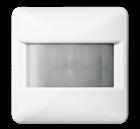
for AS and A ranges
Thermoplastic (breakproof) high-gloss
ivory
white
black
Thermoplastic (breakproof) lacquered
aluminium
champagne
mocha
matt lacquered
matt snow white
matt graphite black
matt anthracite
for CD range
Thermoplastic (breakproof) high-gloss
ivory
white
brown
grey
light grey
black
metal colours (thermoplastic lacquered)
gold-bronze
platinum
for LS range
Thermoplastic (breakproof) high-gloss
ivory
white
light grey
black
matt lacquered
matt snow white
matt graphite black
metal colours (thermoplastic lacquered)
aluminium (lacquered)
stainless steel (lacquered)

anthracite (lacquered)
dark (lacquered)
classic brass (lacquered)
antique brass (lacquered)
Ref.-no.
A 17180
A 17180 WW
A 17180 SW
A 17180 AL
A 17180 CH
A 17180 MO
A 17180 WWM
A 17180 SWM
A 17180 ANM
CD 17180
CD 17180 WW
CD 17180 BR
CD 17180 GR
CD 17180 LG
CD 17180 SW

CD 17180 GB
CD 17180 PT
LS 17180
LS 17180 WW
LS 17180 LG
LS 17180 SW
LS 17180 WWM
LS 17180 SWM
AL 17180
ES 17180
AL 17180 AN
AL 17180 D
ME 17180 C
ME 17180 AT
Standard automatic switch 1.1 m for LB Management inserts "light" ref.-no.: 1701 SE, 1704 ESE, 1702 SE, 1710 DE, 1711 DE, 1713 DSTE, 1723 NE, 1708 IE IP 44 suitable only for indoor installation
Intended use
• Automatic switching of lighting depending on the thermal movement and ambient brightness
• Operation with flush-mounted insert for switching or dimming or satellite insert 3-wire of the LB Management
• Wall installation on flush-mounted insert
Product characteristics
• Extension of the detection area in combination with 3-wire satellite insert
• Operation with 2-wire or 3-wire satellite insert, rotary satellite insert or push-button
• Brightness threshold adjustable
• Sensitivity selectable
• Fixed run-on time
• Switch on with last saved brightness or saved switch-on brightness, with dimming insert

• Switch-on brightness can be saved permanently via satellite unit, with dimmer insert
• Dimming light via satellite unit, with dimmer insert
• Screen for limiting the detection area
Technical data
Ambient temperature: −20 ... +45 °C
Storage/transport temperature: −25 ... +70 °C
Brightness setting: approx. 5 ... 1,000 lx (and daytime operation)
Sensitivity: 25, 50, 75, 100 %
Shut-off delay: approx. 2 min
Mounting height: 1.10 m
Detection angle: 180°
Detection range
Sensitivity 25 %: max. 8 m
Sensitivity 50 %: max. 13 m
Sensitivity 75 %: max. 26 m
Sensitivity 100 %: max. 32 m
for AS and A ranges
Thermoplastic (breakproof) high-gloss


for CD range
Thermoplastic
for LS range
Thermoplastic

Standard automatic switch 2.2 m for LB Management inserts "light" ref.-no.: 1701 SE, 1704 ESE, 1702 SE, 1710 DE, 1711 DE, 1713 DSTE, 1723 NE, 1708 IE Protection level IP 44 is ensured with sealing kit ref.-no. AS A 50 DS and "IP 44 frame" of the respective design range.
IP 44 suitable only for indoor installation
Intended use
• Automatic switching of lighting depending on the thermal movement and ambient brightness
• Operation with flush-mounted insert for switching or dimming or satellite insert 3-wire of the LB Management
• Wall installation on flush-mounted insert
Product characteristics
• Extension of the detection area in combination with 3-wire satellite insert
• Operation with 2-wire or 3-wire satellite insert, rotary satellite insert or push-button
• Brightness threshold adjustable
• Sensitivity selectable
• Fixed run-on time
• Switch on with last saved brightness or saved switch-on brightness, with dimming insert

• Switch-on brightness can be saved permanently via satellite unit, with dimmer insert
• Dimming light via satellite unit, with dimmer insert
Technical data
Ambient temperature: −20 ... +45 °C
Storage/transport temperature: −25 ... +70 °C
Brightness setting: approx. 5 ... 1,000 lx (and daytime operation)
Sensitivity: 25, 50, 75, 100 %
Shut-off delay: approx. 2 min
Mounting height: 1.10 / 2.20 m
Detection angle: 180°
Detection range (2.2 m mounting height)
Sensitivity 25 %: max. 7 m
Sensitivity 50 %: max. 11 m Sensitivity 75 %: max. 13 m
Sensitivity 100 %: max. 15 m
Detection range (1.1 m mounting height) Sensitivity 25 %: max. 7 m Sensitivity 50 %: max. 8 m
Standard automatic switch 2.2 m
for AS and A ranges
Thermoplastic (breakproof) high-gloss
ivory
white
black
Thermoplastic (breakproof) lacquered
aluminium
champagne
mocha
matt lacquered
matt snow white
matt graphite black
matt anthracite
Sealing kit
for automatic switches 2.2 m of the AS / A ranges
IP A 17280
IP A 17280 WW
IP A 17280 SW
IP A 17280 AL
IP A 17280 CH
IP A 17280 MO
IP A 17280 WWM
IP A 17280 SWM
IP A 17280 ANM
To obtain protection level IP 44 IP AS A 50 DS

for CD range
Thermoplastic (breakproof) high-gloss
CD 17280 white
CD 17280 WW
CD 17280 GR
light grey
metal colours (thermoplastic lacquered)
CD 17280 SW
CD 17280 LG black
gold-bronze
for LS range
Thermoplastic (breakproof) high-gloss ivory

white
CD 17280 PT
CD 17280 GB platinum
LS 17280
LS 17280 WW
light grey
matt lacquered
matt snow white
matt graphite black
metal colours (thermoplastic lacquered)
aluminium (lacquered)
LS 17280 SW
LS 17280 LG black
LS 17280 WWM
LS 17280 SWM
AL 17280
stainless steel (lacquered) IP ES 17280

anthracite (lacquered) IP AL 17280 AN
dark (lacquered) IP AL 17280 D
classic brass (lacquered)
antique brass (lacquered)
Sealing kit
for automatic switches 2.2 m of the CD and LS ranges
IP ME 17280 C
IP ME 17280 AT
To obtain protection level IP 44 IP AS CD 50 DS
Universal automatic switch 1.1 m for LB Management inserts "light" ref.-no.: 1701 SE, 1704 ESE, 1702 SE, 1710 DE, 1711 DE, 1713 DSTE, 1723 NE, 1708 IE
Intended use
• Automatic switching of lighting depending on the thermal movement and ambient brightness
• Operation with flush-mounted insert for switching or dimming or satellite insert 3-wire of the LB Management
• Wall installation on flush-mounted insert
Product characteristics
Functions directly via cover
• Extension of the detection area in combination with 3-wire satellite insert
• Continuous on, Continuous off
• Operation with 2-wire or 3-wire satellite insert, rotary satellite insert or push-button
• Dimming insert can be dimmed via satellite insert
• Resetting to factory setting
• Screen for limiting the detection area
Functions via Clever Config App
• Brightness threshold adjustable
• Adjustment of the sensitivity of the PIR sensors

• Run-on time adjustable
• Continuous on, Continuous off
• On or Off for 0.5 – 5 hours
• Switch-off warning
• Dynamic run-on time
• Presence simulation
• Alarm function
• Timer function
• Operating lock
• Reduced basic sensitivity
• Automatic summer/winter time changeover
• Test operation
• Programming of up to 16 individual switching times
In combination with a switch insert
• Short-time operation
In combination with a dimmer insert
• Switch-on with last brightness or saved switch-on brightness
• Adjusting the minimum brightness
• Adjusting the maximum brightness
• Hotel function
• Night light function
Technical data
Ambient temperature: −20 ... +45 °C
Storage/transport temperature: −25 ... +70 °C
Brightness setting: approx. 5 ... 500 lx (and daytime operation)
Sensitivity: 0, 25, 50, 75, 100 %
Shut-off delay: approx. 10 s ... 60 min
Mounting height: 1.10 m
Detection angle: 180°
Detection range
Sensitivity 25 %: max. 8 m
Sensitivity 50 %: max. 13 m
Sensitivity 75 %: max. 26 m
Sensitivity 100 %: max. 32 m
Radio frequency: 2.402 ... 2.480 GHz
Transmitting power: max. 2.5 mW (class 2)
Transmission range: typical 10 m
Universal automatic switch 1.1 m
for AS and A ranges
Thermoplastic (breakproof) high-gloss
ivory
white
black
Thermoplastic (breakproof) lacquered
aluminium
champagne
mocha
matt lacquered
matt snow white
matt graphite black
matt anthracite
for CD range
Thermoplastic (breakproof) high-gloss
ivory
white
brown
grey
light grey
black
metal colours (thermoplastic lacquered)
gold-bronze
platinum
for LS range
Thermoplastic (breakproof) high-gloss
ivory
white
light grey
black
matt lacquered
matt snow white
matt graphite black
metal colours (thermoplastic lacquered)
aluminium (lacquered)
stainless steel (lacquered)


anthracite (lacquered)
dark (lacquered)
classic brass (lacquered)
antique brass (lacquered)
A 17181
A 17181 WW
A 17181 SW
A 17181 AL
A 17181 CH
A 17181 MO
A 17181 WWM
A 17181 SWM
A 17181 ANM
CD 17181
CD 17181 WW
CD 17181 BR
CD 17181 GR
CD 17181 LG
CD 17181 SW

CD 17181 GB
CD 17181 PT
LS 17181
LS 17181 WW
LS 17181 LG
LS 17181 SW
LS 17181 WWM
LS 17181 SWM
AL 17181
ES 17181
AL 17181 AN
AL 17181 D
ME 17181 C
ME 17181 AT
Universal automatic switch 1.1 m for LB Management inserts "light" ref.-no.: 1701 SE, 1704 ESE, 1702 SE, 1710 DE, 1711 DE, 1713 DSTE, 1723 NE, 1708 IE IP 44 suitable only for indoor installation
Intended use
• Automatic switching of lighting depending on the thermal movement and ambient brightness
• Operation with flush-mounted insert for switching or dimming or satellite insert 3-wire of the LB Management
• Wall installation on flush-mounted insert
Product characteristics
Functions directly via cover
• Extension of the detection area in combination with 3-wire satellite insert
• Continuous on, Continuous off
• Operation with 2-wire or 3-wire satellite insert, rotary satellite insert or push-button
• Dimming insert can be dimmed via satellite insert
• Resetting to factory setting
• Screen for limiting the detection area
Functions via Clever Config App
• Brightness threshold adjustable
• Adjustment of the sensitivity of the PIR sensors

• Run-on time adjustable
• Continuous on, Continuous off
• On or Off for 0.5 – 5 hours
• Switch-off warning
• Dynamic run-on time
• Presence simulation
• Alarm function
• Timer function
• Operating lock
• Reduced basic sensitivity
• Automatic summer/winter time changeover
• Test operation
• Programming of up to 16 individual switching times
In combination with a switch insert
• Short-time operation
In combination with a dimmer insert
• Switch-on with last brightness or saved switch-on brightness
• Adjusting the minimum brightness
• Adjusting the maximum brightness
• Hotel function
• Night light function
Technical data
Ambient temperature: −20 ... +45 °C
Storage/transport temperature: −25 ... +70 °C
Brightness setting: approx. 5 ... 500 lx (and daytime operation)
Sensitivity: 0, 25, 50, 75, 100 %
Shut-off delay: approx. 10 s ... 60 min
Mounting height: 1.10 m
Detection angle: 180°
Detection range
Sensitivity 25 %: max. 8 m
Sensitivity 50 %: max. 13 m
Sensitivity 75 %: max. 26 m
Sensitivity 100 %: max. 32 m
Radio frequency: 2.402 ... 2.480 GHz
Transmitting power: max. 2.5 mW (class 2)
Transmission range: typical 10 m
Universal automatic switch 1.1 m

for AS and A ranges
Thermoplastic
for CD range
Thermoplastic

for LS range
Thermoplastic (breakproof) high-gloss


Universal automatic switch 2.2 m for LB Management inserts "light" ref.-no.: 1701 SE, 1704 ESE, 1702 SE, 1710 DE, 1711 DE, 1713 DSTE, 1723 NE, 1708 IE Protection level IP 44 is ensured with sealing kit ref.-no. AS A 50 DS and "IP 44 frame" of the respective design range.
IP 44 suitable for indoor and outdoor installation
Intended use
• Automatic switching of lighting depending on the thermal movement and ambient brightness
• Operation with flush-mounted insert for switching or dimming or satellite insert 3-wire of the LB Management
• Wall installation on flush-mounted insert
Product characteristics
Functions directly via cover
• Extension of the detection area in combination with 3-wire satellite insert
• Continuous on, Continuous off
• Operation with 2-wire or 3-wire satellite insert, rotary satellite insert or push-button
• Dimming insert can be dimmed via satellite insert
• Resetting to factory setting
Functions via Clever Config App
• Brightness threshold adjustable
• Adjustment of the sensitivity of the PIR sensors

• Run-on time adjustable
• Continuous on, Continuous off
• On or Off for 0.5 – 5 hours
• Switch-off warning
• Dynamic run-on time
• Presence simulation
• Alarm function
• Timer function
• Operating lock
• Reduced basic sensitivity
• Automatic summer/winter time changeover
• Test operation
• Programming of up to 16 individual switching times
In combination with a switch insert
• Short-time operation
In combination with a dimmer insert
• Switch-on with last brightness or saved switch-on brightness
• Adjusting the minimum brightness
• Adjusting the maximum brightness
• Hotel function
• Night light function
Technical data
Ambient temperature: −20 ... +45 °C
Storage/transport temperature: −25 ... +70 °C
Brightness setting: approx. 5 ... 500 lx (and daytime operation)
Sensitivity: 0, 25, 50, 75, 100 %
Shut-off delay: approx. 10 s ... 60 min
Mounting height: 1.10 / 2.20 m
Detection angle: 180°
Detection range (2.2 m mounting height)
Sensitivity 25 %: max. 7 m
Sensitivity 50 %: max. 11 m
Sensitivity 75 %: max. 13 m
Sensitivity 100 %: max. 15 m
Radio frequency: 2.402 ... 2.480 GHz
Detection range (1.1 m mounting height)
Sensitivity 25 %: max. 7 m
Sensitivity 50 %: max. 8 m
Sensitivity 75 %: max. 9 m
Sensitivity 100 %: max. 10 m
Transmitting power: max. 2.5 mW (class 2)
Transmission range: typical 10 m
Universal automatic switch 2.2 m
for AS and A ranges
Thermoplastic (breakproof) high-gloss
17281
A 17281 WW black
Thermoplastic (breakproof) lacquered aluminium
A 17281 SW
A 17281 AL
A 17281 CH mocha
A 17281 MO
A 17281 WWM matt graphite black
A 17281 SWM matt anthracite
Sealing kit
for automatic switches 2.2 m of the AS / A ranges
To obtain protection level IP 44
for CD range
Thermoplastic (breakproof) high-gloss
A 17281 ANM
AS A 50 DS
CD 17281
CD 17281 WW
CD 17281 GR light grey
CD 17281 LG
CD 17281 SW metal colours (thermoplastic lacquered) gold-bronze
for LS range
Thermoplastic (breakproof) high-gloss ivory


CD 17281 GB
CD 17281 PT
LS 17281 white
LS 17281 WW
light grey
matt lacquered matt snow white
matt graphite black
metal colours (thermoplastic lacquered)
aluminium (lacquered)
stainless steel (lacquered)
LS 17281 SW
LS 17281 LG black
LS 17281 WWM
LS 17281 SWM
AL 17281
ES 17281
AL 17281 AN dark (lacquered)
anthracite (lacquered)
classic brass (lacquered)
antique brass (lacquered)
Sealing kit
for automatic switches 2.2 m of the CD and LS ranges
To obtain protection level IP 44

AL 17281 D
ME 17281 C
ME 17281 AT
AS CD 50 DS
Ref.-no.
Motion and presence detector for LB Management inserts "light" ref.-no.: 1701 SE, 1704 ESE, 1702 SE, 1710 DE, 1711 DE, 1713 DSTE, 1723 NE, 1708 IE
white
DWPM 17360 WW aluminium (lacquered)
Intended use
• Automatic switching of lighting depending on the thermal movement and ambient brightness
• Operation with flush-mounted insert for switching or dimming or satellite insert 3-wire of the LB Management
• Ceiling mounting on flush-mounted insert
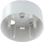

Product characteristics
Functions directly via cover
• Extension of the detection area in combination with 3-wire satellite insert
• Operation with 2-wire or 3-wire satellite insert, rotary satellite insert or push-button
• Dimming light via satellite unit, with dimmer insert
• Resetting to factory setting
• Screen for limiting the detection area
Functions via Clever Config App
• Setting the device as presence detector or motion detector
Technical data
Ambient temperature: −5 ... +45 °C
Storage/transport temperature: −25 ... +70 °C
Dimensions (Ø x H): 103 x 66 mm
Mounting height: 3.00 m
DWPM 17360 AL
• Setting the switch-on threshold
• Separate adjustment of the sensitivity of the three PIR sensors

• Run-on time adjustable
• On or Off
• On or Off for 0.5 – 5 hours
• Switch-off warning
• Dynamic run-on time
• Presence simulation
• Alarm function
• Timer function
• Walking test
• Programming of up to 16 individual switching times
In combination with a switch insert
• Pulse operation
In combination with a dimmer insert
• Constant light control
• Switch-on with last brightness or saved switch-on brightness
• Hotel function
• Night light function
Detection range: Ø approx. 20 m (Mounting height 3 m)
Detection angle: 360°
Sensitivity: 0, 25, 50, 75, 100 %
Brightness threshold
Motion detector operation: approx. 5 ... 500 lx (and daytime operation)
Presence detector operation: approx. 5 ... 1,000 lx (and daytime operation)
Short-time operation
Pulse duration: approx. 0.5 s
Pulse interval: approx. 3 s
Bluetooth
Radio frequency: 2.402 ... 2.480 GHz
Transmitting power: max. 2.5 mW (class 2)
Transmission range: typical 10 m
Surface-mounted housing to fix power units for ceiling installation (surface-mounted) of motion and presence detectors ref.-no. DWPM 17360 WW and DWPM 17360 AL
white PM-KAPPE aluminium (lacquered) PM-KAPPE AL
Technical data
Dimensions (Ø x H): 103 x 45 mm
Motion and presence detector with integrated relay switch including IR remote control ref.-no.: DWPM FB IR K
white
aluminium (lacquered)
Intended use
Ref.-no.
DWPM K 360 WW
DWPM K 360 AL
• Automatic switching of lighting depending on the thermal movement and ambient brightness
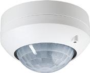

• Ceiling installation, surface mounting in dry indoor areas
Product characteristics
• 2-point light control
• Functions adjustable with IR remote control
• Restriction of the detection field by switching off individual sensors or push-on cover
• Operation with IR remote control, 2-wire extension or installation button
• Teach function for adjustment of the brightness threshold in combination with IR remote control
• Switch-off warning
• Short-time operation, e.g. to activate acoustic signal transmitters
• Display LEDs
• Presence simulation
• Function as twilight switch
• Dynamic run-on time
• Extension of the detection area through parallel switching of multiple devices
Technical data
Rated voltage: AC 110 ... 230 V ~
Mains frequency: 50/60 Hz
Ambient temperature: −5 ... +45 °C
Stand-by power: max. 0.3 W
Circuit breaker: max. 16 A
Contact type: µ
Detection angle: 360°
Dimensions (Ø x H): 103 x 66 mm
Mounting height: 3.00 m
Detection range: Ø approx. 20 m
Sensitivity: 25 ... 100 %
Brightness setting: approx. 5 ... 2,000 lx (and daytime operation)
Shut-off delay: approx. 10 s ... 30 min
Short-time operation
Pulse duration: approx. 0.5 s
Pulse interval: approx. 3 s
Switching current at 35 °C
Ohmic: 16 A (AC1)
Fluorescent lamps: 4 AX
Connected load at AC 230 V ~ and 35 °C
Incandescent lamps: 2300 W
HV halogen lamps: 2000 W
Electronic transformers: 1500 W
Inductive transformers: 1000 VA
HV LED lamps: typical 400 W
Compact fluorescent lamps: typical 400 W
Fluorescent lamps
non-compensated: 920 VA
Capacitive load: 690 VA (560 µF)
Connected load at AC 110 V ~ and 35 °C
Incandescent lamps: 1150 W
HV halogen lamps: 1000 W
Electronic transformers: 750 W
Inductive transformers: 500 VA
HV LED lamps: typical 200 W
Compact fluorescent lamps: typical 200 W
Fluorescent lamps
non-compensated: 460 VA
Capacitive load: 345 VA (560 µF)
Connection single wire: 1 x 1 ... 2.5 mm2
stranded with tin-plated
conductor ends: 1 x 0.75 ... 1.5 mm2
Number of satellite units
unlit installation buttons: unlimited
Satellite insert 2-wire: unlimited
Total length of extension unit cable: max. 100 m
Total length power cable: max. 100 m
IR remote control
Battery type: 1 x lithium CR 2025 (included)
IR remote control for motion and presence detector ref.-no.: DWPM K 360 .. (Spare part)


Battery operation with one included lithium button cell (CR 2025)
IR remote control (electrician) for motion and presence detector ref.-no.: DWPM K 360 ..

Battery operation with one included lithium button cell (CR 2025)
Protection cage for motion and presence detector ref.-no. DWPM 17360 .. (Remove push-on cover when installed in surface-mounted housing. Detection range may be reduced.) for motion and presence detector ref.-no.: DWPM K 360 ..
white SK 180-90 WW
varnished steel with plastic coating dimensions (Ø x H): approx. 180 x 90 mm
Ref.-no.
Room thermostat insert with sensor connection for displays ref.-no.: .. 1790 D ..
Intended use
• Switching of electric underfloor heating systems and electrothermal valve drives
• Operation with room temperature controller cover of the LB Management

• Installation in flush box according to EN 60670-1
Product characteristics
• Pulse width modulation (PWM) or two-point control (on/off)
• Enables connection of a remote sensor (ref.-no.: FF 7.8)
• Input for switching to cooling mode
• Interrupts the heating process after 60 minutes (overheating protection of a heater)
Technical data
Rated voltage: AC 230 V ~
Mains frequency: 50/60 Hz
Stand-by power depending on the cover: approx. 0.1 ... 0.5 W
Switching current 230 V AC1: 10 mA ... 16 A
Connected load: max. 3,600 W
Connection
single wire:
1 x 0.5 ... 4.0 mm2
2 x 0.5 ... 2.5 mm2
stranded without ferrule: 1 x 0.5 ... 4.0 mm2
stranded with ferrule:
2 x 0.5 ... 2.5 mm2
1 x 0.5 ... 4.0 mm2
2 x 0.5 ... 1.5 mm2
Ambient temperature: −5 ... +45 °C
Displays standard for room temperature control see page 264

External temperature sensor for room thermostat ref.-no. 1790 RTR, TR D .. 1790 .. spare part for floor thermostat ref.-no. FTR .. 231 ..
The sensor cable can be connected using a bifilar cable of 1.5 mm2 in diameter that is suitable for mains voltage. When installed in a cable duct or near high voltage current cables, a shielded cable must be used.

FF 7.8
Also suitable as external temperature sensor for the following KNX devices, ref.-no.: .. 2178 TS .., .. 2178 ORTS .., .. 5192 KRM TS D, .. 5194 KRM TS D, 2177 SV R, 23066 REGHE
Technical data
NTC sensor in plastic cap 7.8 mm Ø
Cable length: 4 m
Ambient temperature: −25 ... +70 °C
Display standard for room temperature control for room thermostat insert ref.-no.: 1790 RTR for switch inserts ref.-no.: 1701 SE, 1704 ESE
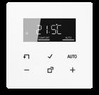

Intended use
• Manual and time-controlled regulation of the room temperature
• Operation with room thermostat insert or switch insert of the LB Management
Product characteristics
• Real glass front panel
• 6 sensor buttons
• Timer with three memory areas
Comfort and ECO time for Mo-Fr and Sa-Su in each memory area
• Setting a comfort, ECO, cooling and frost protection temperature
• Current time can be saved as switching time, quick programming
• Automatic summer/winter time changeover, can be switched off
• Illuminated segment display for easy reading
• Operating lock
• Optimised heating up (temperature is reached at the set time), can be switched off
• Adaptation to valves normally open or normally closed)
• Cooling mode possible
• Supports internal and external temperature sensor
• Temperature drop detection (call-up of frost protection temperature when window is opened)

• Offset adjustment (correction value for measured temperature)
• Controller output working method: pulse width modulation (PWM) or two-point
• Valve protection function (once a week opening and closing of valve, on Saturdays at 11 a.m.)
• Interrupts the heating process after 60 minutes for 5 minutes
• Heating / cooling, switch-over via insert input
• Display switches off after 2 minutes, permanent indication of set/actual temperature or current time possible
Technical data
Ambient temperature: −5 ... +45 °C
Storage/transport temperature: −20 ... +70 °C
Accuracy per month: ± 10 s
Power reserve: > 4 h
for AS and A ranges
white
for CD range white
for LS range white
Ref.-no.
Room thermostat with display standard consists of room thermostat insert (ref.-no.: 1790 RTR) and display (ref.-no.: .. 1790 D ..)

Technical data
Rated voltage: AC 230 V ~
Mains frequency: 50/60 Hz
Stand-by power depending on the cover: approx. 0.1 ... 0.5 W
Switching current 230 V AC1: 10 mA ... 16 A
Connected load: max. 3,600 W
Connection
single wire:
1 x 0.5 ... 4.0 mm2
2 x 0.5 ... 2.5 mm2
stranded without ferrule: 1 x 0.5 ... 4.0 mm2
stranded with ferrule:
2 x 0.5 ... 2.5 mm2
1 x 0.5 ... 4.0 mm2
2 x 0.5 ... 1.5 mm2
Ambient temperature: −5 ... +45 °C
Accuracy per month: ± 10 s
Power reserve: > 4 h
The dimmers in different designs, for flush-mounting, for installation in false ceilings or in the distribution system, can be selected according to the spatial conditions.

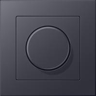
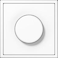

With LB Management, various options are available for future-proof lighting control, including connection to DALI lighting systems.






 LED UNIVERSAL ROTARY DIMMER
Standard rotary dimmer LED incremental control without end position without satellite input
Intended use
• Switching and dimming of lighting
• Operation with suitable cover
• Installation in flush box according to EN 60670-1
Product characteristics
• Device works according to the leading edge phase control or trailing edge phase control principle
• Automatic setting of the dimming principle suitable for the load
• Device can be operated without neutral conductor
• Switch-on via bulb-preserving soft start
• Switch-on with last brightness or saved switch-on brightness
• Switch-on brightness can be saved permanently
• Minimum brightness can be saved permanently
• Electronic short-circuit protection with permanent switch-off after 7 seconds at the latest
• Electronic over-temperature protection

• Power extension possible by means of power boosters (ref.-no. ULZ 1755 REG)
• Optional accessory: compensation module LED, ref.-no.: KM LED 230 U
Technical data
Rated voltage: AC 230 V ~ Mains frequency: 50/60 Hz
Stand-by power: approx. 0.35 W
Power loss: approx. 2 W
Ambient temperature: −5 ... +45 °C
Connected load at 25 °C
Incandescent lamps: 20 ... 210 W
HV halogen lamps: 20 ... 210 W
Electronic transformers: 20 ... 210 W
Electronic transformers with LV LED: typical 20 ... 60 W
Inductive transformers: 20 ... 210 VA
Inductive transformers with LV LED: typical 20 ... 60 VA
Dimmable HV LED lamps: typical 3 ... 60 W
Dimmable compact fluorescent lamps: typical 3 ... 60 W
Ohmic-capacitive: 20 ... 210 W
Capacitive-inductive: not permitted
Ohmic-inductive: 20 ... 210 VA
Ohmic and HV LED: typical 3 ... 60 W
Ohmic and CFL: typical 3 ... 60 W
Operation without neutral conductor: Minimum load 50 W.
Does not apply to loads with HV LED and compact fluorescent lamps.
Amplifiers: see instructions for amplifier
Connection: screw terminals
single wire: 1 x 0.5 ... 4.0 mm2
2 x 0.5 ... 2.5 mm2
stranded without ferrule: 1 x 0.5 ... 4.0 mm2
2 x 0.5 ... 2.5 mm2
stranded with ferrule: 1 x 0.5 ... 4.0 mm2
2 x 0.5 ... 1.5 mm2
Total length power cable: max. 100 m
Ref.-no.
Rotary dimmer universal LED incremental control without end position with satellite input
Intended use
• Switching and dimming of lighting
• Operation with suitable cover
• Installation in flush box according to EN 60670-1
Product characteristics
• Device works according to the leading edge phase control or trailing edge phase control principle
• Automatic or manual setting of the dimming principle suitable for the load
• Display of the set operating mode by means of LED
• Device can be operated without neutral conductor
• Switch-on via bulb-preserving soft start
• Switch-on with last brightness or saved switch-on brightness
• Switch-on brightness can be saved permanently
• Minimum brightness can be saved permanently
• Connection of satellite units possible
• Electronic short-circuit protection with permanent switch-off after 7 seconds at the latest
• Electronic over-temperature protection

• Key card function
• Power extension possible by means of power boosters (ref.-no. ULZ 1755 REG)
• Optional accessory: compensation module LED, ref.-no.: KM LED 230 U
Technical data
Rated voltage: AC 230 V ~
Mains frequency: 50/60 Hz
Stand-by power: approx. 0.35 W
Power loss: approx. 4 W
Ambient temperature: −5 ... +45 °C
Connected load at 25 °C
Incandescent lamps: 20 ... 420 W
HV halogen lamps: 20 ... 420 W
Electronic transformers: 20 ... 420 W
Electronic transformers with LV LED: typical 20 ... 100 W
Inductive transformers: 20 ... 420 VA
Inductive transformers with LV LED: typical 20 ... 100 VA
Dimmable HV LED lamps: typical 3 ... 100 W
Dimmable compact fluorescent lamps: typical 3 ... 100 W
Operating mode LED trailing edge phase control: Rated power for HV LED lamps, typ. 3 ... 400 W, electronic transformers with LV LED typ. 20 ... 200 W.
Ohmic-capacitive: 20 ... 420 W
Capacitive-inductive: not permitted
Ohmic-inductive: 20 ... 420 VA
Ohmic and HV LED: typical 3 ... 100 W
Ohmic and CFL: typical 3 ... 100 W
Amplifiers: see instructions for amplifier
Connection: screw terminals
single wire: 1 x 0.5 ... 4.0 mm2
2 x 0.5 ... 2.5 mm2
stranded without ferrule: 1 x 0.5 ... 4.0 mm2
2 x 0.5 ... 2.5 mm2
stranded with ferrule: 1 x 0.5 ... 4.0 mm2
2 x 0.5 ... 1.5 mm2
Number of satellite units
Rotary satellite insert 3-wire 1733 DNE: 10
Satellite insert 3-wire 1723 NE: 10
Satellite insert 2-wire 1720 NE: unlimited
Push-buttons: unlimited
Total length of extension unit cable: max. 100 m
Total length power cable: max. 100 m
Rotary satellite insert 3-wire
Intended use
• Extension operation for dimmers ref.-no.: 1731 DD, 1711 DE, 1724 DM, UD 1755 REG
• Operation with suitable cover
• Installation in flush box according to EN 60670-1
Technical data
Rated voltage: AC 230 V ~
Mains frequency: 50/60 Hz
Stand-by power: approx. 0.3 W
Ambient temperature: −5 ... +45 °C
Connection: screw terminals single wire: 1 x 0.5 ... 4.0 mm2
2 x 0.5 ... 2.5 mm2 stranded without ferrule: 1 x 0.5 ... 4.0 mm2
2 x 0.5 ... 2.5 mm2 stranded with ferrule: 1 x 0.5 ... 4.0 mm2
2 x 0.5 ... 1.5 mm2
Total length of extension unit cable: max. 100 m
Rotary dimmer insert 100 – 1000 W with 2-way push switch
• Switching and dimming incandescent lamps and HV halogen lamps
• Installation in flush box according to EN 60670-1
• Suitable for mixed operation up to the specified output
Product characteristics
• Dimming method: trailing edge phase control
• Electronic short-circuit protection with permanent switch-off after 7 seconds at the latest

• Electronic over-temperature protection

• Satellite switching possible in combination with 2-way switch
• Optional accessory: compensation module LED, ref.-no.: KM LED 230 U
Technical data
Rated voltage: AC 230/240 V ~, 50 Hz
Ambient temperature: −5 ... +25 °C Connected load at 25 °C
Incandescent lamps: 100 ... 1000 W HV halogen lamps: 100 ... 1000 W
Reduction of load for every 5 °C exceededing 35 °C: −10 % for installation into wooden or hollow walls: −15 % for installation into multiple combinations: −20 %
Connection: screw terminals single wire: max. 4 mm2
Speed regulator
incremental control without end position with satellite input
Intended use
• Speed controller for regulating the speed of single-phase motors e.g. induction motors or shaded pole motors
• Installation in flush box according to EN 60670-1
• Operation with suitable cover
Product characteristics
• Device works according to the leading edge phase control principle
• Device can be operated without neutral conductor
• Switch-on via soft start to maximum speed
• Basic speed can be saved permanently
• Connection of satellite units possible
• Electronic short-circuit protection with permanent switch-off after 100 ms
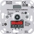
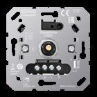
• Electronic over-temperature protection
Technical data
Rated voltage: AC 230 V ~
Mains frequency: 50/60 Hz
Stand-by power: max. 0.5 W
Power loss: max. 4 W
Ambient temperature: −5 ... +45 °C
Switching current: 60 mA ... 1.8 A
Connection: screw terminals single wire: 1 x 0.5 ... 4.0 mm2
2 x 0.5 ... 2.5 mm2
stranded without ferrule: 1 x 0.5 ... 4.0 mm2
2 x 0.5 ... 2.5 mm2
stranded with ferrule: 1 x 0.5 ... 4.0 mm2
2 x 0.5 ... 1.5 mm2
Number of satellite units
Rotary satellite insert 3-wire 1733 DNE: 10
Push-buttons: unlimited
Total length of extension unit cable: max. 100 m
Total length power cable: max. 100 m
Electronic potentiometer, 1 – 10 V for dimming of fluorescent lamps controlled by electronic ballasts or electronic transformers with control voltage 1 – 10 V
with switch function
switching capacity of mains switch:
AC 230 V ~ 50/60 Hz, max. 6 A for resistive loads
Intended use
• Switching and brightness setting for lamps with operating devices with 1 – 10 V interface

• Installation in flush box according to EN 60670-1
Product characteristics
• Potentiometer with switching function for direct switching of ohmic or inductive loads
• Potentiometer with push-button function only in connection with pulse relays
• Minimum brightness can be set
• For potentiometers with a push-button function, switching via extensions is possible
• Protection of the 1 – 10 V interface in case of incorrect connection by means of integrated fine-wire fuse
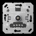
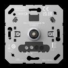
Intended use
• Switching and brightness setting for luminaires with DALI/DALI2 interface
• Setting of colour temperature for luminaires with DALI Device Type 8 for tunable white acc. to IEC 62386-209
• Installation in flush box according to EN 60670-1
Product characteristics
• Certified acc. to IEC 62386-101 and 103 (Single Master)
• Operation as Single Master (no switching in parallel)
• Saving of colour temperature limiting values
• Possibility of storing a basic brightness and a fixed power-on brightness.
1740 DSTE
• Powered using the DALI voltage provided by an external DALI power supply acc. to IEC 62386-101
Technical data
(external DALI power supply acc. to IEC 62386-101 required)
Rated voltage DALI: DC 16 V (typ.)
Power consumption: max. 2 W
Ambient temperature: −5 ... +45 °C
Colour temperature setting: 2,000 ... 10,000 K
Intended use
• Switching and brightness setting for luminaires with DALI/DALI2 interface
• Setting of colour temperature for luminaires with DALI Device Type 8 for tunable white acc. to IEC 62386-209
• Installation in flush box according to EN 60670-1
Product characteristics
• Certified acc. to IEC 62386-101 and 103 (Single Master)

• Operation as Single Master (no switching in parallel)
• Saving of colour temperature limiting values
• Possibility of storing a basic brightness and a fixed power-on brightness.
Technical data
Rated voltage: AC 230 V ~, 50/60 Hz
Power consumption: max. 2 W
Ambient temperature: −5 ... +45 °C
Rated voltage DALI: DC 16 V (typ.)
Output current: max. 56 mA
Short-circuit current: max. 61 mA
Colour temperature setting: 2,000 ... 10,000 K
Output current: max. 56 mA
Number of DALI devices: max. 28
1741 DSTE
Intended use
• Power supply for 12 V halogen lamps
D SNT 105
• Switching and brightness adjustment is performed with DALI control units or push-buttons
• Installation in false ceilings or surface mounting
Product characteristics
• No-load protection
• Electronic short-circuit protection
• Electronic overload protection
• Electronic over-temperature protection

• Suitable for operation in systems with emergency power supply
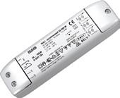
Technical data
Rated capacity: 35 ... 105 W
Rated voltage: AC 230/240 V ~, 50/60 Hz
Output voltage: 11.5 V eff. ~ 40 kHz
Short-circuit protection: electronic protection without fuse
Output cable length: max. 2 m
Dimensions: 170 x 44 x 34 mm
Ambient temperature: max. 50 °C
Terminals: screw terminals
primary 1 x 0.5 ... 1.5 mm2
secondary 1 x 0.75 ... 2.5 mm2
Approvals: VDE
Dimmer mini universal LED with satellite input
Intended use
• Switching and dimming of lighting • Operation takes place with a 2- or 3-wire satellite insert, rotary satellite insert or push-button with make contact (NO) • Installation in flush box according to EN 60670-1 in combination with a suitable cover • Mounting in surface-mounted housing or mounting adapter (ref.-no. FM-EBG) for false ceilings
Product characteristics
• Device works according to the leading edge phase control or trailing edge phase control principle
• Test operation for functional test
• Automatic or manual setting of the dimming principle suitable for the load
• Display of the set operating mode by means of LED
• Device can be operated without neutral conductor
• Switch-on via bulb-preserving soft start
• Switch-on with last brightness or saved switch-on brightness
• Switch-on brightness can be saved permanently
• Minimum brightness can be saved permanently
• Electronic short-circuit protection with permanent switch-off after 7 seconds at the latest
• Electronic over-temperature protection

• Power extension possible by means of power boosters (ref.-no. ULZ 1755 REG)
• Optional accessory: compensation module LED, ref.-no.: KM LED 230 U
Technical data
Rated voltage: AC 230 V ~
Mains frequency: 50/60 Hz
Stand-by power: approx. 0.3 W
Power loss: approx. 2 W
Ambient temperature: −5 ... +45 °C
Connected load at 25 °C
Incandescent lamps: 20 ... 210 W
HV halogen lamps: 20 ... 210 W
Electronic transformers: 20 ... 210 W
Electronic transformers with LV LED: typical 20 ... 50 W
Inductive transformers: 20 ... 210 VA
Inductive transformers with LV LED: typical 20 ... 50 VA
Dimmable HV LED lamps: typical 3 ... 50 W
Dimmable compact fluorescent lamps: typical 3 ... 50 W With setting "LED trailing edge phase control" the max. connection power for HV LED lamps and electronic transformers with LV LED doubles.
Ohmic-capacitive: 20 ... 210 W
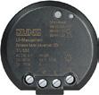
Capacitive-inductive: not permitted
Ohmic-inductive: 20 ... 210 VA
Ohmic and HV LED: typical 3 ... 50 W
Ohmic and CFL: typical 3 ... 50 W
Amplifiers: see instructions for amplifier
Connection: screw terminals
single wire:
stranded without ferrule:
stranded with ferrule:
Number of satellite units
1 x 0.75 ... 2.5 mm2
2 x 0.75 ... 1.5 mm2
1 x 1.0 ... 4.0 mm2
2 x 1.0 ... 2.5 mm2
1 x 1.0 ... 2.5 mm2
2 x 1.0 ... 1.0 mm2
Satellite insert 2-wire 1720 NE: unlimited
Satellite insert 3-wire 1723 NE: 10
Rotary satellite insert 3-wire 1733 DNE: 10
unlit installation buttons: unlimited
Total length of extension unit cable: max. 100 m
Total length power cable: max. 100 m
Dimensions (Ø x H): 48 x 19.5 mm
Ref.-no.
Universal dimmer LED, built-in with satellite input
Intended use
• Switching and dimming of lighting • Operation takes place with a 2- or 3-wire satellite insert, rotary satellite insert or push-button with make contact (NO) • Mounting in false ceilings
Product characteristics
• Device works according to the leading edge phase control or trailing edge phase control principle
• Test operation for functional test
• Automatic or manual setting of the dimming principle suitable for the load
• Display of the set operating mode by means of LED
• Device can be operated without neutral conductor
• Switch-on via bulb-preserving soft start
• Switch-on with last brightness or saved switch-on brightness
• Switch-on brightness can be saved permanently
• Minimum brightness can be saved permanently
• Electronic short-circuit protection with permanent switch-off after 7 seconds at the latest
• Electronic over-temperature protection

• Power extension possible by means of power boosters (ref.-no. ULZ 1755 REG)
• Optional accessory: compensation module LED, ref.-no.: KM LED 230 U
Technical data
Rated voltage: AC 230 V ~
Mains frequency: 50/60 Hz
Stand-by power: approx. 0.3 W
Power loss: approx. 2 W
Ambient temperature: −5 ... +45 °C
Connected load at 25 °C
Incandescent lamps: 20 ... 210 W
HV halogen lamps: 20 ... 210 W
Electronic transformers: 20 ... 210 W
Electronic transformers with LV LED: typical 20 ... 50 W
Inductive transformers: 20 ... 210 VA
Inductive transformers with LV LED: typical 20 ... 50 VA
Dimmable HV LED lamps: typical 3 ... 50 W
Dimmable compact fluorescent lamps: typical 3 ... 50 W With setting "LED trailing edge phase control" the max. connection power for HV LED lamps and electronic transformers with LV LED doubles.
Ohmic-capacitive: 20 ... 210 W
Capacitive-inductive: not permitted
Ohmic-inductive: 20 ... 210 VA
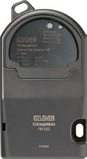
Ohmic and HV LED: typical 3 ... 50 W
Ohmic and CFL: typical 3 ... 50 W
Amplifiers: see instructions for amplifier
Connection
Connection mode: screw terminals
single wire:
stranded without ferrule:
stranded with ferrule:
Number of satellite units
1 x 0.75 ... 2.5 mm2
2 x 0.75 ... 1.5 mm2
1 x 1.0 ... 4.0 mm2
2 x 1.0 ... 2.5 mm2
1 x 1.0 ... 2.5 mm2
2 x 1.0 ... 1.0 mm2
Satellite insert 2-wire 1720 NE: unlimited
Satellite insert 3-wire 1723 NE: 10
Rotary satellite insert 3-wire 1733 DNE: 10
unlit installation buttons: unlimited
Total length of extension unit cable: max. 100 m
Total length power cable: max. 100 m
Dimensions: 53 x 97 x 36 mm (W x H x D)
Universal dimmer LED
Rail mounting device, 2 rail units
1-channel
Intended use
• Switching and dimming of lighting
• Mounting on DIN rail according to EN 60715 in distribution boxes
Ref.-no.
UD 1755 REG
• Operation takes place using the buttons, 2- or 3-wire satellite insert, rotary satellite insert or push-button with make contact (NO)
Product characteristics
• Device works according to the leading edge phase control or trailing edge phase control principle
• Automatic or manual setting of the dimming principle suitable for the load
• Display of the set operating mode by means of LED
• Switch-on via bulb-preserving soft start
• Switch-on with last brightness or saved switch-on brightness
• Switch-on brightness can be saved permanently
• Minimum brightness can be saved permanently
• Electronic short-circuit protection with permanent switch-off after 7 seconds at the latest
• Electronic over-temperature protection

• Power extension possible by means of power boosters (ref.-no. ULZ 1755 REG)
• Optional accessory: compensation module LED, ref.-no.: KM LED 230 U
Technical data
Rated voltage: AC 230 V ~
Mains frequency: 50/60 Hz
Stand-by power: approx. 0.3 W
Power loss: approx. 3.8 W
Ambient temperature: −5 ... +45 °C
Connected load at 25 °C
Incandescent lamps: 20 ... 420 W
HV halogen lamps: 20 ... 420 W
Electronic transformers: 20 ... 420 W
Electronic transformers with LV LED: 20 ... 100 W
Inductive transformers: 20 ... 420 VA
Inductive transformers with LV LED: 20 ... 100 VA
Dimmable HV LED lamps: typical 3 ... 100 W
Dimmable compact fluorescent lamps: typical 3 ... 100 W

Operating mode LED trailing edge phase control: Rated power for HV LED lamps, typ. 3 ... 400 W, electronic transformers with LV LED typ. 20 ... 200 W.
Ohmic-capacitive: 20 ... 420 W
Capacitive-inductive: not permitted
Ohmic-inductive: 20 ... 420 VA
Ohmic and HV LED: typical 3 ... 100 W
Ohmic and CFL: typical 3 ... 100 W
Amplifiers: see instructions for amplifier
Connection: screw terminals single wire: 1 x 0.75 ... 4.0 mm2
2 x 0.75 ... 2.5 mm2 stranded without ferrule: 1 x 0.75 ... 4.0 mm2
2 x 0.75 ... 2.5 mm2 stranded with ferrule: 1 x 0.5 ... 2.5 mm2
Number of satellite units
Satellite insert 2-wire 1720 NE: unlimited
Satellite insert 3-wire 1723 NE: 10
Rotary satellite insert 3-wire 1733 DNE: 10
unlit installation buttons: unlimited
Total length of extension unit cable: max. 100 m
Total length power cable: max. 100 m
Mounting width: 36 mm (2 rail units)
Ref.-no.
Amplifier LED
Rail mounting device, 2 rail units
Intended use
• Power extension of the listed dimmers (ref.-no.: UD 1755 REG, 1730 DD, 1731 DD, 1710 DE, 1711 DE, 1712 DE, FM UD 20250 UP, FM UD 5500 REG, FM UD 420250 REG, 3901 REGHE, 3902 REGHE, 39004 1S R)
• Mounting on DIN rail according to EN 60715 in distribution boxes

Product characteristics
• Connection of several amplifiers to a single dimmer
• The total power of the connected loads is divided between the dimmer and amplifiers
• Power is supplied to the connected loads via a common power cable
• Operation using upstream dimmer
• Electronic over-temperature protection

• Optional accessory: compensation module LED, ref.-no.: KM LED 230 U
Technical data
Rated voltage: AC 230 V ~
Mains frequency: 50/60 Hz
Stand-by power: approx. 0.5 W
Power loss: approx. 4.3 W
Ambient temperature: −5 ... +45 °C
Connection: screw terminals
single wire: 1 x 0.75 ... 4.0 mm2
2 x 0.75 ... 2.5 mm2
stranded without ferrule: 1 x 0.75 ... 4.0 mm2
2 x 0.75 ... 2.5 mm2
stranded with ferrule: 1 x 0.5 ... 2.5 mm2
Total length power cable: max. 100 m
Mounting width: 36 mm (2 rail units)
Permissible load depends on dimmer, operation mode and type of load, see operating instructions
Compensation module LED
Intended use
KM LED 230 U
• Use in combination with JUNG Tronic dimmers or universal dimmers in trailing edge phase control mode which are operated with dimmable HV LED lamps (ref.-no.: 1224 LED UDE, 1252 UDE, 1710 DE, 1711 DE, 1712 DE, 1724 DM, 1724 DEB, 1730 DD, 1731 DD, 211 GDE, 225 TDE, 254 UDIE1, 3901 REGHE, 3902 REGHE, 39004 1S REGHE, 824 TDW, FM UD 20250 UP, FM UD 420250 REG, FM UD 5500 REG, UD 1255 REG, UD 1755 REG, ULZ 1755 REG, UDS 4 REGHE)
• Use in combination with illuminated switches which are operated with dimmable HV LED lamps
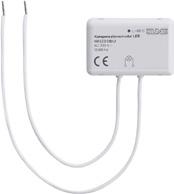
• Use indoors
• Installation in lamp, flush box according to EN 60670-1 or distribution box
The module is used to:
• improve the dimming behaviour of dimmers which are not optimised for HV-LED lamps
• to avoid that HV LED lamps which are connected to a dimmer glow when switched off
• to avoid that HV LED lamps which are connected to a switch with illumination (up to 3 mA) glow when they are switched off
Technical data
Rated voltage: AC 230 V ~
Mains frequency: 50/60 Hz
Power loss: max. 2 W
Housing temperature: max. 65 °C
Cable length: approx. 150 mm
Dimensions (W x H x D): 43 x 11.5 x 28.5 mm
Ref.-no.
TRONIC transformer
Technical data
Rated capacity: 10 ... 40 W
Rated voltage: AC 230 V ~, 50/60 Hz
Output voltage: 11.7 V eff. ~ 50 kHz
Short-circuit protection: electronic protection without fuse
Output cable length: max. 2 m
Dimensions (W x H x D): 73 x 35.5 x 18 mm
Ambient temperature: max. 50 °C
Housing temperature: max. 85 °C
Length of connected cables: approx. 210 mm
Approvals: VDE
TRONIC transformer
Technical data
SNT 40
SNT 70 Q
Rated capacity: 20 ... 60 W T = 50 °C / 20 ... 70 W T = 40 °C
Rated voltage: AC 230 V ~, 50/60 Hz
Output voltage: 11.7 V eff. ~ 40 kHz
Short-circuit protection: electronic protection without fuse
Output cable length: max. 2 m
Dimensions (W x H x D): 49 x 48 x 28 mm
Ambient temperature: max. 50 °C (60 W)
Housing temperature: max. 75 °C
Length of connected cables: approx. 210 mm
Approvals: VDE
TRONIC transformer
Technical data
Rated capacity: 20 ... 105 W
Rated voltage: AC 230 V ~, 50/60 Hz
Output voltage: 11.8 V eff. ~ 40 kHz
Short-circuit protection: electronic protection without fuse
Output cable length: max. 2 m
Dimensions (W x H x D): 175 x 42 x 18 mm
Ambient temperature: max. 50 °C
Housing temperature: max. 80 °C
Terminals
primary screw terminals (2 pairs) secondary screw terminals (3 pairs)
Approvals: VDE
TRONIC transformer
Technical data
Rated capacity: 35 ... 105 W
Rated voltage: AC 230 V ~, 50 Hz

Output voltage: 11.7 V eff. ~ 40 kHz
Short-circuit protection: electronic protection without fuse
Output cable length: max. 2 m
Dimensions (W x H x D): 172.5 x 42 x 18 mm
Ambient temperature: max. 50 °C

Housing temperature: max. 75 °C
Terminals
primary screw terminals (2 pairs) secondary cable length approx. 210 mm
Approvals: VDE
SNT 105 F
SNT 105-35
TRONIC transformer
Technical data
Rated capacity: 20 ... 150 W
Rated voltage: AC 230 V ~, 50/60 Hz
Output voltage: 11.7 V eff. ~ 40 kHz
Short-circuit protection: electronic protection without fuse
Output cable length: max. 1 m
Dimensions (W x H x D): 176 x 42 x 38 mm
Ambient temperature: max. 50 °C
Housing temperature: max. 75 °C
Terminals
primary screw terminals (2 pairs) secondary screw terminals (3 pairs)
Approvals: VDE
TRONIC transformer
Technical data
Rated capacity: 50 ... 210 W
Rated voltage: AC 230 V ~, 50 Hz
Output voltage: 11.5 V eff. ~ 40 kHz
Short-circuit protection: electronic protection without fuse
Output cable length: max. 2 m
Dimensions (W x H x D): 212 x 48.5 x 46 mm
Ambient temperature: max. 45 °C
Housing temperature: max. 65 °C
Terminals
primary screw terminals (2 pairs) secondary screw terminals (2 pairs)
Approvals: VDE
Push-button controller, built-in for dimming of fluorescent lamps controlled by electronic ballasts or electronic transformers with control voltage 1 – 10 V
operation by push-buttons (NO contact), e.g. ref.-no. 531 U
Intended use
• Switching and brightness setting of luminaires with 1 – 10 V interface


• Installation in false ceilings or surface mounting
Product characteristics
Ref.-no.
SNT 150
SNT 200
• The light bulb is switched on and off via the load cable and dimmed via the 1 – 10 V interface
• Operation via installation button, NO contact
• Can be switched to memory function with brightness memory
• The 1 – 10 V interface is short-circuit proof for the control current
Technical data
Rated voltage: AC 230 V ~, 50 Hz
Switch contact: relay, mains potential
Switching capacity
Ohmic load: 2300 W
Electronic ballast, transformer: depending on type
Control current of electronic ballast: max. 200 mA
Short-circuit protection: line circuit breaker, max. 10 A
Electrical isolation: 2 kV basic insulation
Ambient temperature: max. 50 °C
No-load protection: yes
Connection mode: screw terminals single wire: max. 4 mm2 stranded without ferrule: max. 2.5 mm2 stranded with ferrule: max. 1.5 mm2
Dimensions (W x H x D): 175 x 42 x 18 mm
The relay station has eight floating contacts for switching, sensing and moving blinds / shutters. The functions are possible in mixed operation. The lighting and automatic shading control can be centrally controlled with the central function. Connection in parallel of two relay stations or of a relay station with a dimming station is possible.

The dimming station has four channels for dimming and switching of lighting. It provides all features of a JUNG dimmer. The fade-out function can be used when switching off. Connection in parallel of two dimming stations or of a dimming station with a relay station is possible.
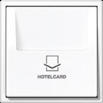

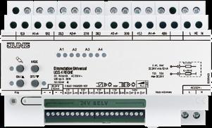
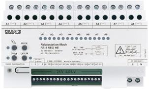
The JUNG bus is the installation solution using 24 volt technology, suitable for everything from a private apartment to a hotel. A crucial aspect is simple installation and use. The system requires only a few devices and little wiring.

Ref.-no. Relay station
Relay station universal, 8-gang Rail mounting device, 8 rail units with manual electronic operation and LED status indication 8 NO contacts
Intended use
• Switching of lighting
• Switching of single-phase fan motors
• Switching of electrically-driven blinds, shutters, awnings and similar hangings
• Mounting on DIN rail in distribution boxes
RS 8 REGHE
• Operation by means of sensor modules, push-button modules, or unlit installation buttons


Product characteristics
• Local control. The relay station can be controlled using the keypad when the control units are not connected.
• Activation of status LEDs on the control units. The relay station has the activation outputs A1’...A8’ for this purpose.
• Switching operation
• Push-button operation
• Blind operation with slat adjustment
• Mixed operation of switching, push-button and blind control is possible.
• Central switching function All On, All Off
Technical data
Rated voltage: AC 230/240 V ~, 50/60 Hz
Power loss: 12.5 W
Stand-by power: 0.5 W
Length of control cable: max. 100 m
Number of control units
Sensor module (ref.-no. SM 1608): max. 4 (also when relay/dimming stations are connected in parallel)
Push-button module 24 V AC/DC (NO contact): depending on push-button module, consider current consumption
Push-button module (ref.-no. 4008 TSM): max. 4 (also when relay/dimming stations are connected in parallel)
Control units
Voltage: DC 24 V SELV
Current carrying capacity: Σ 80 mA
Switching inputs E1 ... E8
Resistance Ri: 200 kΩ
Control voltage: DC 24 V SELV
Activation outputs A1' ... A8'
Resistance Ra: 330 Ω
Control voltage: DC 24 V SELV
Current carrying capacity: 10 mA
Connection, mains and load outputs
Connection mode: screw terminals
single wire: 1 x 1.5 ... 4 mm2
stranded without ferrule: 1 x 0.75 ... 4 mm2
stranded with ferrule: 1 x 0.5 ... 2.5 mm2
Connection of switching inputs, activation outputs and control units
Connection mode: screw terminals
single wire: 1.5 mm2
stranded without ferrule: 1 mm2
stranded with ferrule: 0.75 mm2
Load outputs A1 ... A8
Contact type: floating NO contact (µ contact)
Breaking capacity per load output: AC 250 V ~ / 16 AX
Switching current, load outputs: Σ 80 A
Switching current neighbouring load outputs: Σ 20 A
Loads per output
Ohmic load: 3000 W
Capacitive load: 16 A / max. 140 µF
Blind / Fan motors: 1380 VA
Switch-on current: max. 800 A (200 µs) max. 165 A (20 ms)
Lamp loads
Incandescent lamps: 3000 W
HV halogen lamps: 2500 W
LV halogen lamps with electronic transformers: 1500 W
inductive transformers: 1200 VA
Fluorescent lamps
non-compensated: 1000 W
parallel compensated: 1160 W / 140 µF
lead-lag circuit: 2300 W / 140 µF
Electronic ballast: depending on type
Minimum load: AC 12 V, 100 mA
Ambient temperature: −5 ... +45 °C
Storing temperature: −25 ... +70 °C

Mounting width: 144 mm (8 rail units)
Change-over time for direction change: 1 s
Switch-on time, blinds operation: 2 min
LED universal dimming station 4-gang Rail mounting device, 8 rail units
Intended use
UDS
• Switching and dimming of incandescent lamps, HV halogen lamps, dimmable HV LED lamps, dimmable compact fluorescent lamps, dimmable inductive transformers with LV halogen or LV LED lamps, dimmable electronic transformers with LV halogen or LV LED lamps
• Suitable for mixed load up to the specified output
• Operation by means of push-button sensors, sensor modules, push-button modules or unlit installation buttons
• Operation by means of push-button sensors, sensor modules, push-button modules or unlit installation buttons
• Installation in distribution boxes on DIN rail according to EN 60715
• It is not possible to operate the device with universal amplifiers in conjunction with electronic transformers! Please use TRONIC amplifiers for power extension when operating electronic transformers.
Product characteristics
• The dimming station can be controlled using the keypad.
• Activation of status LEDs on the control units. The dimming station has the activation outputs A1’...A4’ for this purpose.
• Electronic short-circuit protection with permanent switch-off after 7 seconds at the latest
• Electronic over-temperature protection

• Integrated memory function for each channel (storing of brightness value)
• Switch-on brightness can be saved permanently
• Switch-on via bulb-preserving soft start
• Switching off with dim-down function
• Increase in output power possible through parallel switching of multiple outputs

• Power extension possible by means of power boosters (ref.-no. ULZ 1755 REG)
• Special connection for hotel card switch
• Central switching function All On, All Off
• Parallel connection of two dimming stations or one dimming and one relay station possible
• Automatic setting of the dimming principle suitable for the load
• Optional accessory: compensation module LED, ref.-no.: KM LED 230 U
In combination with a hotel card switch (ref.-no.: .. CARD ..): When plugging in the hotel card the light will be switched on with the stored brightness level. After removing the hotel card the light remains on and can be controlled for 1 more minute. After the elapsed time the light dims down (within an adjustable time of 30 seconds to 3 minutes) to minimum brightness and then switches off. The dimming station can be controlled again after plugging in the hotel card.
Technical data
Rated voltage: AC 230/240 V ~, 50/60 Hz
Power loss: max. 20 W
Stand-by power: max. 2 W
Terminals -, +
Control voltage: DC 24 V SELV
Current carrying capacity: Σ 80 mA
Length of control cable: max. 100 m
Number of control units
Sensor module (ref.-no. SM 1608): max. 4 (also when relay/dimming stations are connected in parallel)
Push-button module (ref.-no. 4008 TSM): max. 4 (also when relay/dimming stations are connected in parallel)
Push-button module 24 V AC/DC (NO contact): depending on push-button module, consider current consumption
Switching inputs E1ON/OFF ... E4ON/OFF
Control voltage: DC 24 V SELV
Resistance Ri: 200 kΩ
Activation outputs A1' ... A4'
Control voltage: DC 24 V SELV
Current carrying capacity: 10 mA
Resistance Ra: 330 Ω
Mains / load outputs / key card switch
Connection mode: screw terminals single wire: 1 x 1.5 ... 4 mm2
stranded without ferrule: 1 x 0.75 ... 4 mm2
stranded with ferrule: 1 x 0.5 ... 2.5 mm2
Connection of switching inputs, activation outputs and control units
Connection mode: screw terminals single wire: 1.5 mm2
stranded without ferrule: 1 mm2
stranded with ferrule: 0.75 mm2
Load outputs A1 ... A4
Contact type: ε
Length of output cable, per channel: max. 100 m
Connected load per channel
Incandescent lamps: 20 ... 150 W
HV halogen lamps: 20 ... 150 W
Electronic transformers: 20 ... 150 W
Inductive transformers: 20 ... 150 VA
Dimmable HV LED lamps: typical 3 ... 30 W
Dimmable compact fluorescent lamps: typical 3 ... 30 W
Ohmic-capacitive: 20 ... 150 W
Ohmic-inductive: 20 ... 150 VA
Capacitive-inductive: not permitted
Reduction of load for every 5 °C
exceededing 45 °C: –15 %

Max. load for outputs connected in parallel is limited to 80 %.
Mounting width: 144 mm (8 rail units)
Sensor module (JUNG bus) for the connection of relay station (ref.-no. RS 8 REGHE) and dimming station (ref.-no. UDS 4 REGHE) Only in combination with frames of the LS range and FLAT DESIGN

SM 1608
Features
• Up to 16 load outputs of the relay or dimming station can be controlled
• Switching, push-button, dimming, blind
• Light scenes: up to 4 light scenes per control point can be freely configured
• Central function: all assigned load outputs are switched on/off centrally
• Free assignment of the sensor surfaces to the load outputs, central functions and light scenes
• Settings can be changed
• LEDs can be used as feedback and as orientation light
• Feedback of switching states on all connected sensor modules
• LED brightness adjustable in 3 stages (100 %, 50 %, OFF)
• Up to 4 sensor modules can be connected to a single relay/dimming station, even with stations connected in parallel
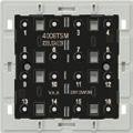
• Cloning: transfer of a set assignment to another sensor module
• If mains power fails, assignments are retained
• Simple installation via 2-wire cable
• Labelling possible with JUNG Graphic Tool
Technical data
Power supply: DC 24 V SELV (via relay or dimming station)
Current consumption: max. 20 mA (all LEDs on)
Connection: bus connection block
Inscription field (W x H): 68.5 x 68.5 mm
Ambient temperature: +5 ... +45 °C
Storing temperature: −25 ... +75 °C
Push-button module (JUNG bus)
for the connection of relay station (ref.-no. RS 8 REGHE) and dimming station (ref.-no. UDS 4 REGHE)
Adapter frames are included in delivery: ref.-no. LS 4 AR for LS range (pre-mounted) and ref.-no. CD 4 AR for CD range. AS / A ranges without adapter frame.
Product characteristics
• 8 channels of the relay station can be controlled: switching, push-button control, blind control
• 16 channels of 2 parallel-wired relay stations can be controlled in combination with push-button extension module ref.-no.: 4094 TSEM
• All station channels are switchable in delivery state
• Central function: all selected station channels are controlled centrally
• Light scenes: up to four light scenes can be set freely
• Push-buttons can be assigned according to cover kit
• Programming without additional tools
• Free assignment of the groups to the channels
• Red LED as status indicator (can be switched off)

• Blue operation LED (can be switched off)
• Status feedback of the switching states to connected push-button modules and sensor modules
• Up to 4 push-button modules with max. 4 extension modules can be connected to single or parallel connected relay/dimming stations
• Cloning of modules: transfer the assignment of one module to further modules
• Cloning of push-button modules with extension module is possible
• Simple installation via 2-wire cable
Technical data
Power supply: DC 24 V SELV (via relay or dimming station)
Current consumption: max. 20 mA (all LEDs on)
Connection mode: connection terminal
Ambient temperature: +5 ... +25 °C
Storing temperature: −25 ... +75 °C
Push-button extension module for the extension of up to 8 additional push-buttons for the push-button module ref.-no. 4008 TSM preferred installation: vertical Adapter frames are included in delivery: ref.-no. LS 4 AR for LS range (pre-mounted) and ref.-no. CD 4 AR for CD range. AS / A ranges without adapter frame.

8 red LED: status indication

4-gang
Cover kits for AS and A ranges see page 671
Cover kits for CD range see page 672
Cover kits for LS range see page 673
Ref.-no.
F 50 Push-button modules for connection to relay station ref.-no. RS 8 REGHE, dimming station ref.-no. UDS 4 REGHE or other control systems with control voltage of max. 24 V AC/DC (SELV), 20 mA. The module is connected by means of a connection block at the back.
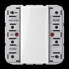

• To be completed with cover kit
• One red status LED per button

In combination with the PHC system of the company PEHA the proper functioning of the status LED cannot be guaranteed. Please contact our technical service line.

Push-button module 24 V AC/DC, 20 mA for AS and A ranges
including transparent cover ref.-no.: A 50 NA
Cover kits for AS and A ranges see page 662
Push-button module 24 V AC/DC, 20 mA for CD range
including transparent cover ref.-no.: CD 50 NA
Cover kits for CD range see page 665
Push-button module 24 V AC/DC, 20 mA for LS range
including transparent cover ref.-no.: LS 50 NA
Cover kits for LS range see page 668
Ref.-no.
F 40 Push-button modules for connection to relay station ref.-no. RS 8 REGHE, dimming station ref.-no. UDS 4 REGHE or other control systems with control voltage of max. 24 V AC/DC (SELV), 20 mA. The module is connected by means of a connection block at the back. To each push-button two red LEDs are assigned for status indication.
In combination with the PHC system of the company PEHA the proper functioning of the status LED cannot be guaranteed. Please contact our technical service line.

Push-button module 24 V AC/DC, 20 mA
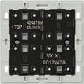
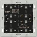

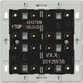
Adapter frames are included in delivery:
ref.-no. LS 4 AR for LS range (pre-mounted) and ref.-no. CD 4 AR for CD range. AS / A ranges without adapter frame.
Cover kits for AS and A ranges see page 671
Cover kits for CD range see page 672
Cover kits for LS range see page 673
Decoupling relay
For blinds control if more than one motor should be connected to a mechanical switch/push-button or a motor control insert. The relay is designed for two drives.
Technical data
Rated voltage: AC 230 V ~, 50 Hz
Control: AC 230 V ~, 50 Hz
Switching capacity: 4 A, AC 230 V ~ cos ϕ ≥ 0.8 ind.
Duty cycle: 100 %
Decoupling relay for rail mounting

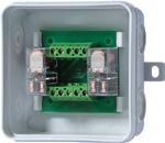
Rail mounting device, 2.5 rail units
For blinds control if more than one motor should be connected to a mechanical switch/push-button or a motor control insert. The relay is designed for two drives.
Technical data
Rated voltage: AC 230 V ~, 50 Hz
Control: AC 230 V ~, 50 Hz
Switching capacity: 4 A, AC 230 V ~ cos ϕ ≥ 0.8 ind.
Duty cycle: 100 %
Decoupling relay, flush-mounted
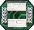
For blinds control if more than one motor should be connected to a mechanical switch/push-button or a motor control insert. The relay is designed for two drives. Decoupling relay for flush-mounting in wall box (deep wall box recommended).
Technical data

Rated voltage: AC 230 V ~, 50 Hz
Control: AC 230 V ~, 50 Hz
Switching capacity: 4 A, AC 230 V ~ cos ϕ ≥ 0.8 ind.
Duty cycle: 100 %
Ref.-no.
TR-S
TR-S REG
TR-SUP
Ref.-no.
Weather station
Rail mounting device, 6 rail units
In connection with the digital combi sensor WS10 KS and the power supply unit WSSV10, the weather station WSK100 REG measures brightness, wind intensity and rain. Based on brightness and wind intensity, the station controls a connected shutter control system independently for the east, south and west sides of a house. When the combi sensor detects rain, the windows or skylights can be closed automatically.
Features
• Independent outputs for the shutters of the east, south and west facade of a house
• Separately adjustable shading function for the east, south and west facade
• Presettable common limit value for the wind alarm for the three house facades
• Precipitation detect function with switched ouput, e.g. for the control of skylights
• Standard shutter moving time of 2.5 minutes in sun protection mode can be shortened independently for each facade
• Monitoring of combination sensor connection cable with alarm function and message display
The weather station has to be supplied with the external power supply WSSV 10.


Technical data
Power supply
Supply voltage: AC 24 V ~ ± 15 %
Current consumption: max. 300 mA
Ambient temperature: −5 ... +45 °C
Storage/transport temperature: −25 ... +70 °C
Humidity
Ambient/storage/transport: max. 93 % r. h., no condensation
Mounting width: 108 mm (6 rail units)
Terminals
Inputs, power supply: screw terminals
single wire: 1 x 0.5 ... 4 mm2
stranded without ferrule: 1 x 0.34 ... 4 mm2
stranded with ferrule: 1 x 0.14 ... 2.5 mm2
Combi sensor WS 10 KS: 4-pole WAGO terminal Type 252-104
Outputs: relay (NO contacts) 8 x 250 V / 8 A
Precipitation: yes / no
Potentiometer "sensor": approx. 0 ... 76 klx
Hysteresis: ± 5 %
Potentiometer "wind": 1 ... 20 m/s, OFF
Position 1: approx. 5 m/s
Position 2: approx. 10 m/s
Position 3: approx. 15 m/s
Hysteresis: ± 5 %

Ref.-no.
Power supply AC 24 V ~ for weather station ref.-no.: WSK 100 REG and for Combi sensor ref.-no.: WS 10 KS Rail mounting device, 4 rail units
Intended use
• Supplying devices with 24 V AC
• Mounting on DIN rail according to EN 60715 in distribution boxes

Product characteristics
• Two internally connected 24 V outputs
• Overload and short-circuit protection via thermo switch
Technical data
Rated voltage: AC 230 V ~, 50/60 Hz
Output current: max. 1 A
Output voltage: AC 24 V ~
Storage/transport temperature: −25 ... +70 °C
Ambient temperature: −5 ... +40 °C
Relative humidity: max. 93 % r. h., no condensation
Mounting width: 72 mm (4 rail units)
Connection: screw terminals single wire: 1 x 0.5 ... 4 mm2 stranded with ferrule: 1 x 0.14 ... 2.5 mm2 stranded without ferrule: 1 x 0.34 ... 4 mm2
WSSV 10
Combi sensor
Ref.-no.
WS 10 KS
The combi sensor serves for the measurement of the wind speed, brightness dawn and rain. The brightness can be measured for three directions, south, east and west, separately. It will be connected directly to the weather station which evaluates the measured data. The combi sensor needs 24 V AC for operation. The necessary power can be supplied by the power supply unit ref.-no.: WSSV 10.
Technical data
Power supply
Sensor unit (incl. heating): AC 24 V ~ ± 15 %, 50/60 Hz
Max. power consumption: 600 mA
Connection
Connection cable: LiYCY, 6 x 0.25 mm2, shielded
Length: 10 m, max. 50 m
Ambient conditions
Ambient temperature: –40 ... +60 °C (ice free)

Storage/transport temperature: −40 ... +60 °C
Humidity: outside the building
Housing
Protection level: IP 55 in position for use acc. to EN 60529
Protection class: III
Dimensions (Ø x H): 130 x ca. 200 mm (without mounting bracket)
Mounting: mounting bracket for wall or mast
Weight: approx. 330 g (without mounting bracket)
Sensor signals:
Wind sensor
Measuring range: approx. 1 ... 40 m/s
Accuracy: ≤ 0.5 m/s, −20 ... +60 °C
Precipitation sensor
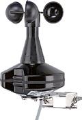
Measuring range: precipitation yes / no
Sensitivity: fine drizzle
Switch-on delay: approx. 3 rain particles
Switch-off delay: approx. 2 min
Brightness sensor
Measuring range: approx. 1 ... 110 klx
Spectral range: approx. 700 ... 1050 nm
Direction: east, south, west
Dawn sensor
Measuring range: approx. 0 ... 674 lx
Rain sensor
Intended use
• Sensor for detection and evaluation of precipitation
• In connection with blind/shutter controllers, enables, e.g. the retraction of awnings when it begins to rain.
• Surface-mounted devices for outdoor installation
Product characteristics
• Serpentine-shaped sensor surface detects wetting due to precipitation.
• Change-over relay remains switched on until the sensor is dry again. For at least 10 minutes.
• Integrated heater speeds up the drying of the sensor surface and melts snow and ice.
Technical data
Rated voltage: AC 230 V ~, 50/60 Hz
Current consumption: 15 mA (with preheating)
Power consumption: max. 4.5 W (incl. auxiliary heating)
Switch-off delay: approx. 10 min
Relay output dry: contact open rain: contact closed
Relay switching capacity: max. 1500 W (resistive load)
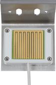
Relay contact rating: (µ) 6 A / AC 250 V ~
Ambient temperature: −30 ... +50 °C
Protection class: II
Protection level: IP 65
Connection cable: flexible PVC cord, 2.9 m, JZ-600, 3 x 0.75 mm2 2.9 m, JZ-600, 2 x 0.75 mm2
Dimensions: 130 x 90 x 90 mm (incl. fitting bracket)
Weight: approx. 600 g (incl. fitting bracket)
Mounting position: fixed by 110° fitting bracket
Wind sensor with converter
Intended use
• The converter and wind sensor are used to protect a blind/shutter against destruction due to excessively strong winds. The blind/shutter is moved to a safe end position and locked there until the wind drops below the set wind speed value.
• The converter is operated together with a Universal blinds insert (ref.-no. 1731 JE) or binary inputs of the KNX system.
• Surface-mounted devices for outdoor installation
Product characteristics
• Detection and evaluation of wind speeds
• 8 wind speeds can be set
• The wind alarm is triggered 15 seconds after the set wind speed threshold value is exceeded
• Test operation for functional test
• Colour of wind sensor: black (similar RAL 9005)


Technical data
Rated voltage: AC 230 V ~, 50 Hz
Protection level: IP 55
Protection class: II
Switching current: max. 2 A
Contact type: floating NO contact (µ contact)
Connection: screw terminals single wire: max. 4 mm2 stranded without ferrule: max. 2.5 mm2 stranded with ferrule: max. 1.5 mm2
Switch-on delay: approx. 15 s
Switch-off delay: approx. 15 min
Ref.-no.
Wind sensor (Spare part) for connection to converter ref.-no.: AT 04..
black similar RAL 9005
132 WS
Use shielded cable (J-Y(St)Y 2x2x0.6mm2 is recommended) to connect the wind sensor.
Converter (Spare part) for connection of wind sensor ref.-no.: 132 WS
Intended use
132 U
• The converter and wind sensor are used to protect a blind/shutter against destruction due to excessively strong winds. The blind/shutter is moved to a safe end position and locked there until the wind drops below the set wind speed value.
• The converter is operated together with a Universal blinds insert (ref.-no. 1731 JE) or binary inputs of the KNX system.

• Surface-mounted devices for outdoor installation
Product characteristics
• Detection and evaluation of wind speeds
• 8 wind speeds can be set
• The wind alarm is triggered 15 seconds after the set wind speed threshold value is exceeded
• Test operation for functional test
• Colour of wind sensor: black (similar RAL 9005)
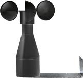

Technical data
Rated voltage: AC 230 V ~, 50 Hz
Protection level: IP 55
Protection class: II
Switching current: max. 2 A
Contact type: floating NO contact (µ contact)
Connection: screw terminals
single wire: max. 4 mm2
stranded without ferrule: max. 2.5 mm2
stranded with ferrule: max. 1.5 mm2
Switch-on delay: approx. 15 s
Switch-off delay: approx. 15 min
Awning control, AeroTec 04
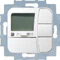
Thermoplastic (breakproof) high-gloss white
The AeroTec timer may be used to operate sun protection systems only
Ref.-no.
AT 04 WW
The AeroTec timer is pre-programmed ex works with current date and time (CET) settings and operates sun protection systems on the basis of sunlight intensity and wind speed. The AeroTec timer can be operated manually at any time. The device runs on battery power, meaning it can even be programmed if the operating device has been removed, as the display does not disappear.
• Controller for awnings
• 15 languages (Display)
• Ex works pre-programmed
• Sensors can be connected
• Manual control always possible
• Additional switching time
• Adjustable inside position
• Cloth stretching function
Technical data
Rated voltage: AC 230/240 V ~, 50/60 Hz
Switching current: 5 A / 250 V AC cos ϕ = 1
Switching capacity: max. 1 motor 1000 W
Battery type: 1 button cell CR 2032 (included)

When cell is replaced, values previously set will be preserved.
Output: 2 relays, floating contacts (NO contacts)
Input: Brightness sensor (ref.-no.: LA 90)
Sunlight / wind sensor (ref.-no.: AR 04)
Wind sensor (ref.-no.: VT 04)
Rain sensor (ref.-no.: RW 95)

Connection: screw terminals
Terminals for: 2.5 mm2
Always use shielded control wire ... 0.8 mm Ø or J-ST-Y ... 0.6 mm Ø
Intermediate frame to install "AeroTec 04" in AS and A ranges
white
Frames
AS 500 (ref.-no.: AS 581.. – AS 585..)
A 550 (ref.-no.: A 5581.. – A 5585..)
A FLOW (ref.-no.: AF 581.. – AF 585..)
A CREATION (ref.-no.: AC 581.. – AC 585..)
surface cap (ref.-no.: AS 581 A.. – AS 583 A..)
Intermediate frame to install "AeroTec 04" in CD range
A AT 581 Z WW
white CD AT 581 Z WW
Frames
CD 500 (ref.-no.: CD 581.. – CD 585..)
CD PLUS (ref.-no.: CDP 581.. – CDP 585..)
surface cap (ref.-no.: CD 581 A.. – CD 583 A..)
Ref.-no.
The wind sensor should be fitted to the roof or house wall. It must be installed at a position suitable for wind intensity measurements. Do not install at the side sheltered from the wind.
Sunlight / wind sensor for connection to awning control "AeroTec 04", ref.-no.: AT 04 WW

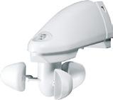
Ensure that no shadows (e.g. from a mast, tower, etc.) and no light reflections fall on the brightness sensor.
Technical data
Protection level: IP 43
Rain sensor
Intended use
• Sensor for detection and evaluation of precipitation

• In connection with blind/shutter controllers, enables, e.g. the retraction of awnings when it begins to rain.
• Surface-mounted devices for outdoor installation
Product characteristics
• Serpentine-shaped sensor surface detects wetting due to precipitation.
• Change-over relay remains switched on until the sensor is dry again. For at least 10 minutes.
• Integrated heater speeds up the drying of the sensor surface and melts snow and ice.
Technical data
Rated voltage: AC 230 V ~, 50/60 Hz
Current consumption: 15 mA (with preheating)
Power consumption: max. 4.5 W (incl. auxiliary heating)
Switch-off delay: approx. 10 min
Relay output dry: contact open rain: contact closed
Relay switching capacity: max. 1500 W (resistive load)

Relay contact rating: (µ) 6 A / AC 250 V ~
Ambient temperature: −30 ... +50 °C
Protection class: II
Protection level: IP 65
Connection cable: flexible PVC cord, 2.9 m, JZ-600, 3 x 0.75 mm2 2.9 m, JZ-600, 2 x 0.75 mm2
Dimensions: 130 x 90 x 90 mm (incl. fitting bracket)
Weight: approx. 600 g (incl. fitting bracket)
Mounting position: fixed by 110° fitting bracket
Brightness sensor for connection to awning control "AeroTec 04", ref.-no.: AT 04 WW
LA 90
Electronic valve drive
AC 230 V ~
Electric floor heating system
AC 230 V ~
Electronic valve drive
AC 230 V ~
Electric floor heating system


AC 230 V ~
Ventilator
The room thermostat with display and clock for time-controlled individual room temperature: Individual switching times as well as different temperature levels can be set. The self-explanatory user guidance and the display with plain text are particularly user-friendly. Summer and winter time are
Room thermostat with display


Room thermostat
Room thermostat


Floor thermostat
Humidistat
automatically changed over; the preset time programs can be individually adjusted. A remote sensor can be optionally connected. The version without clock basically has the same functions, but without time programming, holiday programs etc.
The temperature management includes controllers with normally closed and changeover contacts and floor thermostats.The room thermostat with display standard controls both water-based and electric underfloor heating systems and radiators. In combination with a modern heat pump system, it also enables room cooling. It consists of the flush-mounted room thermostat insert with sensor connection and the Standard display cover for room temperature control.
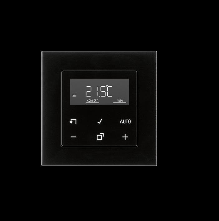

Ref.-no.
Room thermostat insert with sensor connection for displays ref.-no.: .. 1790 D ..
Intended use
• Switching of electric underfloor heating systems and electrothermal valve drives
• Operation with room temperature controller cover of the LB Management

• Installation in flush box according to EN 60670-1
Product characteristics
• Pulse width modulation (PWM) or two-point control (on/off)
• Enables connection of a remote sensor (ref.-no.: FF 7.8)
• Input for switching to cooling mode
1790 RTR
• Interrupts the heating process after 60 minutes (overheating protection of a heater)
Technical data
Rated voltage: AC 230 V ~ Mains frequency: 50/60 Hz
Stand-by power depending on the cover: approx. 0.1 ... 0.5 W
Switching current 230 V AC1: 10 mA ... 16 A
Connected load: max. 3,600 W
Connection
single wire: 1 x 0.5 ... 4.0 mm2
2 x 0.5 ... 2.5 mm2
stranded without ferrule: 1 x 0.5 ... 4.0 mm2
2 x 0.5 ... 2.5 mm2
stranded with ferrule: 1 x 0.5 ... 4.0 mm2
2 x 0.5 ... 1.5 mm2
Ambient temperature: −5 ... +45 °C
External temperature sensor for room thermostat ref.-no. 1790 RTR, TR D .. 1790 .. spare part for floor thermostat ref.-no. FTR .. 231 ..
The sensor cable can be connected using a bifilar cable of 1.5 mm2 in diameter that is suitable for mains voltage. When installed in a cable duct or near high voltage current cables, a shielded cable must be used.

FF 7.8
Also suitable as external temperature sensor for the following KNX devices, ref.-no.: .. 2178 TS .., .. 2178 ORTS .., .. 5192 KRM TS D, .. 5194 KRM TS D, 2177 SV R, 23066 REGHE
Technical data
NTC sensor in plastic cap 7.8 mm Ø
Cable length: 4 m
Ambient temperature: −25 ... +70 °C
Ref.-no.
Display standard for room temperature control for room thermostat insert ref.-no.: 1790 RTR for switch inserts ref.-no.: 1701 SE, 1704 ESE

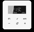
Intended use
• Manual and time-controlled regulation of the room temperature
• Operation with room thermostat insert or switch insert of the LB Management
Product characteristics
• Real glass front panel
• 6 sensor buttons
• Timer with three memory areas
Comfort and ECO time for Mo-Fr and Sa-Su in each memory area
• Setting a comfort, ECO, cooling and frost protection temperature
• Current time can be saved as switching time, quick programming
• Automatic summer/winter time changeover, can be switched off
• Illuminated segment display for easy reading
• Operating lock
• Optimised heating up (temperature is reached at the set time), can be switched off
• Adaptation to valves normally open or normally closed)
• Cooling mode possible
• Supports internal and external temperature sensor
• Temperature drop detection (call-up of frost protection temperature when window is opened)

• Offset adjustment (correction value for measured temperature)
• Controller output working method: pulse width modulation (PWM) or two-point
• Valve protection function (once a week opening and closing of valve, on Saturdays at 11 a.m.)
• Interrupts the heating process after 60 minutes for 5 minutes
• Heating / cooling, switch-over via insert input
• Display switches off after 2 minutes, permanent indication of set/actual temperature or current time possible
Technical data
Ambient temperature: −5 ... +45 °C
Storage/transport temperature: −20 ... +70 °C
Accuracy per month: ± 10 s
Power reserve: > 4 h

Ref.-no.
Room thermostat with display standard consists of room thermostat insert (ref.-no.: 1790 RTR) and display (ref.-no.: .. 1790 D ..)
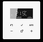
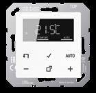
Technical data
Rated voltage: AC 230 V ~
Mains frequency: 50/60 Hz
Stand-by power depending on the cover: approx. 0.1 ... 0.5 W
Switching current 230 V AC1: 10 mA ... 16 A
Connected load: max. 3,600 W
Connection
single wire: 1 x 0.5 ... 4.0 mm2
2 x 0.5 ... 2.5 mm2 stranded without ferrule: 1 x 0.5 ... 4.0 mm2
2 x 0.5 ... 2.5 mm2 stranded with ferrule: 1 x 0.5 ... 4.0 mm2
2 x 0.5 ... 1.5 mm2
Ambient temperature: −5 ... +45 °C
Accuracy per month: ± 10 s
Power reserve: > 4 h
for AS and A ranges
for CD range
for LS range
Room thermostat (1-way contact)
Screwless terminals for wires up to 2.5 mm2
screw fixing only, without claws
1-pole NC contact 10 (4) A, AC 230 V ~, 50/60 Hz
(The value in brackets indicates inductive loads with cos ϕ = 0.6)
Thermal feedback (neutral conductor required)
Hysteresis: 0.5 K, nominal range: +5 °C ... +30 °C
Separate terminal for temperature reduction of 5 K (e.g. during night time)

ON/OFF switch with status LED
When set temperature is reached the contact opens up.
for AS and A ranges
Thermoplastic (breakproof) high-gloss
Thermoplastic (breakproof) lacquered
for CD range
Thermoplastic (breakproof) high-gloss
for SL range
Room thermostat (1-way contact)
for
Room thermostat (1-way contact)
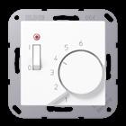
Screwless terminals for wires up to 2.5 mm2
screw fixing only, without claws
1-pole NC contact 10 (4) A, AC 24 V ~
(The value in brackets indicates inductive loads with cos ϕ = 0.6)
Thermal feedback (neutral conductor required)
Hysteresis: 0.5 K, nominal range: +5 °C ... +30 °C
Separate terminal for temperature reduction of 5 K (e.g. during night time)

ON/OFF switch with status LED
When set temperature is reached the contact opens up.
for AS and A ranges
Thermoplastic (breakproof) high-gloss
(breakproof) lacquered
Room thermostat (1-way contact)


for CD range
Thermoplastic (breakproof) high-gloss
ivory
white
brown
grey
light
black
metal
gold-bronze
platinum
for SL range
white
gold-bronze
black
for LS range
Thermoplastic (breakproof) high-gloss

Room thermostat (2-way contact)
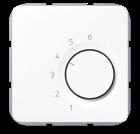
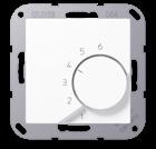
Screwless terminals for wires up to 2.5 mm2
screw fixing only, without claws
1-pole, 2-way, heating 10 (4) A, AC 230 V ~, 50/60 Hz
1-pole, 2-way, cooling 5 (2) A, AC 230 V ~, 50/60 Hz
For switching between heating/cooling the EBERLE terminal strip EV..H/K is necessary.
(The value in brackets indicates inductive loads with cos ϕ = 0.6)
Thermal feedback (neutral conductor required)
Hysteresis: 0.5 K, nominal range: +5 °C ... +30 °C
No OFF-position
Without switch and control LED
When set temperature is reached the NO/NC contact switches over.
for AS and A ranges
Thermoplastic (breakproof) high-gloss
(breakproof) lacquered
for CD range
versions (anodized aluminium)
Room thermostat (2-way contact) for SL range
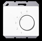
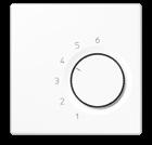
white TR SL 236 WW
gold-bronze
black

TR SL 236 GB
TR SL 236 SW
for LS range
Thermoplastic (breakproof) high-gloss
ivory TR LS 236
white TR LS 236 WW
light grey TR LS 236 LG
black TR LS 236 SW
matt lacquered
matt snow white TR LS 236 WWM
matt graphite black TR LS 236 SWM
metal versions
aluminium TR AL 236
stainless steel
anthracite (aluminium lacquered)
dark (aluminium lacquered)
TR ES 236
TR AL 236 AN
TR AL 236 D
chrome TR GCR 236
gold-coloured TR GO 236
gold-plated TR LS 236 GGO
classic brass TR ME 236 C
antique brass TR ME 236 AT

Ref.-no.
Room thermostat (2-way contact)
Screwless terminals for wires up to 2.5 mm2
screw fixing only, without claws
1-pole, 2-way, heating 10 (4) A, AC 24 V ~
1-pole, 2-way, cooling 5 (2) A, AC 24 V ~
(The value in brackets indicates inductive loads with cos ϕ = 0.6)
Thermal feedback (neutral conductor required)
Hysteresis: 0.5 K, nominal range: +5 °C ... +30 °C
No OFF-position
Without switch and control LED
When set temperature is reached the NO/NC contact switches over.
for AS and A ranges
Thermoplastic (breakproof) high-gloss
Thermoplastic (breakproof) lacquered
for CD range
Thermoplastic (breakproof) high-gloss
versions (anodized aluminium)
Room thermostat (2-way contact) for SL range


white
gold-bronze
black
for LS range
Thermoplastic (breakproof) high-gloss
ivory
white
light grey
black
metal versions
aluminium
stainless
anthracite
chrome
gold-coloured
gold-plated
classic
antique
Ref.-no.
Floor thermostat
Screwless terminals for wires up to 2.5 mm2 screw fixing only, without claws
1-pole NO contact 10 A, AC 230 V ~, 50/60 Hz for control of electrical floor heating and floor temperature systems with NTC remote sensor (length: 4 m, Ø 7.8 mm)
Neutral conductor required
Hysteresis: 1 K
Nominal range: +10 °C ... +50 °C
Separate terminal for temperature reduction of 5 K (e.g. during night time)

On/off switch
LED red: heating
LED green: temperature reduction active
Non-floating relay contact
Heating interruption acc. to EN 50559: Within one hour of permanent heating the controller automatically interrupts the heating process for 5 minutes.
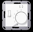
for AS and A ranges
Thermoplastic (breakproof) high-gloss
(breakproof) lacquered
for CD range
Thermoplastic (breakproof) high-gloss
versions (anodized aluminium)
Floor thermostat
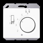
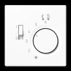
for SL range
white FTR SL 231 WW
gold-bronze FTR SL 231 GB
black FTR SL 231 SW
for LS range
Thermoplastic (breakproof) high-gloss
ivory FTR LS 231

white FTR LS 231 WW
light grey FTR LS 231 LG
black FTR LS 231 SW
metal versions
aluminium FTR AL 231
stainless steel FTR ES 231
anthracite (aluminium lacquered) FTR AL 231 AN
dark (aluminium lacquered) FTR AL 231 D
chrome FTR GCR 231
gold-coloured FTR GO 231
gold-plated FTR LS 231 GGO
classic brass FTR ME 231 C
antique brass FTR ME 231 AT

Ref.-no.
External temperature sensor for room thermostat ref.-no. 1790 RTR, TR D .. 1790 .. spare part for floor thermostat ref.-no. FTR .. 231 ..
FF 7.8
Also suitable as external temperature sensor for the following KNX devices, ref.-no.: .. 2178 TS .., .. 2178 ORTS .., .. 5192 KRM TS D, .. 5194 KRM TS D, 2177 SV R, 23066 REGHE

Technical data
NTC sensor in plastic cap 7.8 mm Ø
Cable length: 4 m

Ambient temperature: −25 ... +70 °C
Thermal valve drive AC 230 V ~
Intended use
Operation of straightway and 3-way valves. For controller with switched output, 2-point regulation or pulse width modulation (PWM), in combination with single room control systems. Suitable for retrofitting of existing heating systems with corresponding adapter.
Product characteristics
• Forceless installation onto the valve
• Visible and haptic position indication
• Noiseless
• Maintenance-free
Technical data
Rated voltage: AC 230 V ~, 50/60 Hz
Function: valve in closed position when power is off (NC)
Power consumption during operation: 2.5 W
Switch-on current: 250 mA
Valve lift: max. 4.5 mm
Run time for 4.5 mm valve lift: approx. 3.5 min
Spring power: max. 125 N
Ambient temperature: 0 ... +50 °C
Thread: M 30 x 1.5
Mounting position: all positions possible
Colour: white (similar RAL 9016)
Ref.-no.
Adapter set for valve drive ref.-no.: TVA 230 NC WW

Closing dimensions with white cap: 4.5 ... 9.5 mm with black cap: 8.5 ... 13.5 mm without cap: 13.5 ... 18.5 mm

M 30 x 1.5
M 30 x 1.0
M 28 x 1.5
Adapter For mounting on Danfoss valve RA-N (RA 2000)
ASET 3015
ASET 3010
ASET 2815
A 110

Ref.-no.
Temperature controller fan coil, 2-pipe
Intended use
• Switching and operating electrical fan coil units with electrothermically actuated heating/cooling valves
• Measurement and feedback control of the room temperature
• Installation in flush box according to EN 60670-1 (recommendation: deep box)
Product characteristics
• Connection of one fan coil unit with up to 3 fan speeds
• Heating or cooling mode
• Real glass front panel
• 8 capacitive sensor buttons
• Internal temperature sensor
• Room temperature controller function
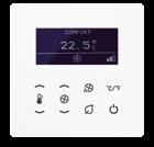
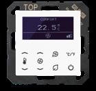
• Preselection of the current energy level through the option of 5 temperature profiles for use in hotels or similar sites
• Display for indication of actual temperature (°C or °F), fan speed, operating mode/profile

• Menu levels blockable
• 1 status LED (red/green/blue)
• Display brightness and contrast adjustable
• Duration of the display illumination up to 120 seconds
• Satellite input for connection of key card holder
Technical data
Rated voltage: AC 110 ... 230 V ~ Mains frequency: 50/60 Hz
Switching output
Contact type: µ
Output current: max. 3 A
Switching capacity
Motors (230 V): 690 VA
Motors (110 V): 300 VA
Outputs for valve drives
Contact type: semiconductor (triac), ε
Switching current: max. 250 mA
Storing temperature: −5 ... +45 °C
Transport temperature: −25 ... +70 °C
Ambient temperature: −5 ... +45 °C
Relative humidity: 5 ... 95 % (no condensation)
Connection mode: screw terminals
single wire: 1.5 mm2
stranded with ferrule: 1.5 mm2
for AS and A ranges
white TRD A 523028 WW
black TRD A 523028 SW
for LS range
white TRD LS 923028 WW
black TRD LS 923028 SW

Ref.-no.
Power supply for temperature controller fan coil (2-pipe) ref.-no.: TRD ..23028 .. (Spare part)
Technical data
Rated voltage: AC 110 ... 230 V ~
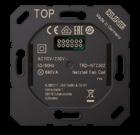
Mains frequency: 50/60 Hz
Switching output
Contact type: µ
Output current: max. 3 A
Switching capacity
Motors (230 V): 690 VA
Motors (110 V): 300 VA
Outputs for valve drives
Contact type: semiconductor (triac), ε
Switching current: max. 250 mA
Storing temperature: −5 ... +45 °C
Transport temperature: −25 ... +70 °C
Ambient temperature: −5 ... +45 °C
Relative humidity: 5 ... 95 % (no condensation)
Connection mode: screw terminals
single wire: 1.5 mm2
stranded with ferrule: 1.5 mm2
TRD-NT 2302
Ref.-no.
Temperature controller fan coil, 4-pipe
Intended use
• Switching and operating electrical fan coil units with electrothermically actuated heating/cooling valves
• Measurement and feedback control of the room temperature
• Installation in flush box according to EN 60670-1 (recommendation: deep box)
Product characteristics
• Connection of one fan coil unit with up to 3 fan speeds
• Heating and/or cooling mode
• Real glass front panel
• 8 capacitive sensor buttons
• Internal temperature sensor
• Room temperature controller function

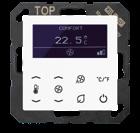
• Preselection of the current energy level through the option of 5 temperature profiles for use in hotels or similar sites
• Display for indication of actual temperature (°C or °F), fan speed, operating mode/profile

• Menu levels blockable
• 1 status LED (red/green/blue)
• Display brightness and contrast adjustable
• Duration of the display illumination up to 120 seconds
• Satellite input for connection of key card holder
Technical data
Rated voltage: AC 110 ... 230 V ~
Mains frequency: 50/60 Hz
Switching output
Contact type: µ
Output current: max. 3 A
Switching capacity
Motors (230 V): 690 VA
Motors (110 V): 300 VA
Outputs for valve drives
Contact type: semiconductor (triac), ε
Switching current: max. 250 mA
Storing temperature: −5 ... +45 °C
Transport temperature: −25 ... +70 °C
Ambient temperature: −5 ... +45 °C
Relative humidity: 5 ... 95 % (no condensation)
Connection mode: screw terminals single wire: 1.5 mm2 stranded with ferrule: 1.5 mm2
for AS and A ranges
white TRD A 523048 WW
black TRD A 523048 SW
for LS range
white TRD LS 923048 WW
black TRD LS 923048 SW

Ref.-no.
Power supply for temperature controller fan coil (4-pipe) ref.-no.: TRD ..23048 .. (Spare part)
Technical data
Rated voltage: AC 110 ... 230 V ~
Mains frequency: 50/60 Hz
Switching output

Contact type: µ

Output current: max. 3 A
Switching capacity
Motors (230 V): 690 VA
Motors (110 V): 300 VA
Outputs for valve drives
Contact type: semiconductor (triac), ε
Switching current: max. 250 mA
Storing temperature: −5 ... +45 °C
Transport temperature: −25 ... +70 °C
Ambient temperature: −5 ... +45 °C
Relative humidity: 5 ... 95 % (no condensation)
Connection mode: screw terminals
single wire: 1.5 mm2
stranded with ferrule: 1.5 mm2
Display for temperature controller fan coil ref.-no.: TRD ..230.. (Spare part)
TRD-NT 2304
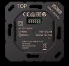
Humidistat
Intended use
The hygrostat regulates the humidity of the air in order to create a healthy room climate. This helps to prevent damage from mould and mildew.
• Measurement of air humidity in rooms
• Control of 230 V heating and ventilation appliances
• Installation in flush box according to EN 60670-1
Product characteristics
• Measurement of room temperature and air humidity to determine the optimal content of moisture in the air
• Control of heating and ventilation appliances for the removal of moisture in rooms
• Manual control range approx. 20 ... 95 % or fixed value of 60 % relative humidity

• Control knob for manual adjustment of the setpoint
• Modes of operation: automatic, manual, party, standby
• Status LED
• Time-controlled continuous operation
Function
The humidistat uses an integrated sensor to measure the moisture and temperature in the room. If the humidity exceeds a value set previously on the knob on the humidistat, a connected device is activated to dehumidify the room.
Technical data
Rated voltage: AC 230 V ~
Mains frequency: 50/60 Hz
Ambient temperature: 0 ... +45 °C
Storing temperature: −20 ... +70 °C
Storage humidity: 20 ... 60 % relative humidity (r. h.)
Contact: floating NO contact
Contact type: µ
Switching voltage AC: max. 230 V
Switching current AC1 (cos ϕ > 0.8): 15 mA ... 8 A
Switching current AC3 (cos ϕ < 0.8): 15 mA ... 4 A
Motors: 15 mA ... 4 A
Switching voltage DC: max. 24 V
Switching current DC: 15 mA ... 8 A
Control range: 20 ... 95 % relative humidity (r. h.)
Measuring tolerance: ± 5 % r. h.
Switching difference: ± 2 %
Length of output cable (≥ 1.5 mm2): max. 100 m
Connection mode: screw terminals
Terminals for: 2.5 mm2
Mounting height: approx. 1.5 m
Humidistat
for AS and A ranges
Thermoplastic (breakproof) high-gloss ivory
black
Thermoplastic (breakproof) lacquered
aluminium
mocha
for CD range
Thermoplastic (breakproof) high-gloss ivory
for LS range
Thermoplastic (breakproof) high-gloss

JUNG provides British Standard components for typical BS wall boxes. The elaborated modular system enables the simple installation of cover, socket and design frame in a 1-gang or 2-gang version. High quality materials in the LS ranges or the full plate version achieve an elegant view.
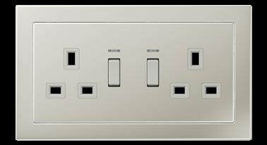
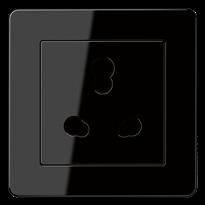
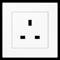 BRITISH STANDARD SOCKET 13 A
BRITISH STANDARD 2-GANG SOCKET 13 A, SWITCHABLE WITH INDICATOR LAMP
BRITISH STANDARD SOCKET 5 A
in A 550 in white
in LS DESIGN in stainless steel
in A FLOW in black
The covers without visible screws compose a plane appearance. The British Standard sockets are available in all LS metal finishes and of course in duroplastic material in ivory, white and black.
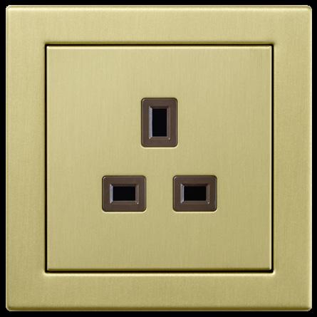
Sockets are the basis of every electrical installation. For a smooth and fast installation, JUNG supplies British sockets from the factory with the appropriate support ring.


For the installation of a 2-gang wall box in the British system, JUNG offers various 2-gang sockets with a large support ring. In combination with the design frames from the JUNG A 550, A FLOW and LS Design, the electrical installation is given a high-quality appearance.



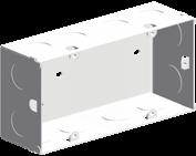


Ideal for renovations: JUNG technology with adapter frame. With this method, installers can install versatile building technology, without extensive restoration work or a reconfiguration of the electrical installation under the plaster.


Switched socket insert British Standard 1363 for rectangular British Standard wall boxes Screw terminals for wires up to 4 mm2

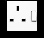
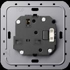
1-gang
2-pole, 13 A 250 V ~

without indicator light
with indicator light
Centre plates for A 550 / A FLOW
ivory A 3171 PL white A 3171 WW PL black A 3171 SW PL Duroplastic
lacquered
Duroplastic
ivory A 3171 KO PL white A 3171 KO WW PL black A 3171 KO SW PL Duroplastic lacquered aluminium A 3171 KO AL PL champagne A 3171 KO CH PL mocha A 3171 KO MO PL Thermoplastic
(breakproof) high-gloss
Centre plates for LS DESIGN (special BS frame) Ref.-no.
Centre plate for socket insert ref.-no. BS 2171 EINS only in combination with frames ref.-no. BS 2181 ..

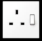

Duroplastic (scratch-proof) glossy
Centre plate for socket insert ref.-no. BS 2171 KO EINS only in combination with frames ref.-no. BS 2181 ..
Duroplastic (scratch-proof) glossy
Ref.-no.
Socket insert British Standard 1363 for rectangular British Standard wall boxes Screw terminals for wires up to 4 mm2
1-gang
2-pole, 13 A 250 V ~

without switch
2521 EINS
Centre plates for A 550 / A FLOW
ivory A 3521 PL white A 3521 WW PL black A 3521 SW PL
Duroplastic lacquered
Centre plates for LS DESIGN (special BS frame)
Centre plate for socket insert ref.-no. BS 2521 EINS only in combination with frames ref.-no. BS 2181 ..

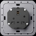
(scratch-proof)
ivory BS 2521 PL white BS 2521 WW PL light grey BS 2521 LG PL black BS 2521 SW PL matt lacquered matt snow white BS 2521 WWM PL matt graphite black BS 2521 SWM PL metal
versions
Switched socket insert British Standard 1363 for rectangular British Standard wall boxes
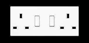

Screw terminals for wires up to 4 mm2
2-gang
2-pole, 13 A 250 V ~
without indicator light
with indicator light
The inserts enable the flush installation into rectangular British Standard wall boxes. Combinations with other devices into multiple frames are NOT possible.
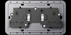
Centre plates for A 550 / A FLOW
Centre plate for socket insert ref.-no. BS 2172 EINS only in combination with 2-gang frames ref.-no. A 5582-0 .., AF 582-0 ..
Thermoplastic (breakproof) high-gloss

Thermoplastic (breakproof) lacquered

Centre plates for A 550 / A FLOW
Centre plate for socket insert ref.-no. BS 2172 KO EINS only in combination with 2-gang frames ref.-no. A 5582-0 .., AF 582-0 ..
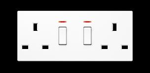
Thermoplastic (breakproof) high-gloss

(breakproof) lacquered

Centre plates for LS DESIGN (special BS frame)
Centre plate for socket insert ref.-no. BS 2172 EINS only in combination with 2-gang frames ref.-no. BS 2182 ..
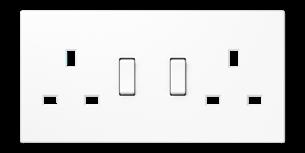

Duroplastic (scratch-proof) glossy

Centre plates for LS DESIGN (special BS frame)
Centre plate for socket insert ref.-no. BS 2172 KO EINS only in combination with 2-gang frames ref.-no. BS 2182 ..
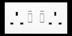

(scratch-proof) glossy

Socket insert British Standard 1363 for rectangular British Standard wall boxes 2-gang
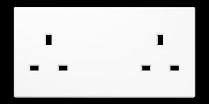
Screw terminals for wires up to 4 mm2 2-pole, 13 A 250 V ~
without switch
Ref.-no.
BS 2522 EINS

The inserts enable the flush installation into rectangular British Standard wall boxes. Combinations with other devices into multiple frames are NOT possible.
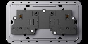
Centre plates for LS DESIGN (special BS frame)
Centre plate for socket insert ref.-no. BS 2522 EINS only in combination with 2-gang frames ref.-no. BS 2182 ..
Duroplastic (scratch-proof) glossy
ivory
white
black
matt lacquered
matt snow white
matt graphite black
metal versions
aluminium
stainless
anthracite (aluminium lacquered) BS 2522 AN


dark (aluminium lacquered) BS 2522 ALD
chrome
gold-coloured
classic
antique
Switched socket insert British Standard 546 for rectangular British Standard wall boxes Screw terminals for wires up to 4 mm2 2-pole, 15 A 250 V ~ only in combination with full plates ref.-no. BS 2171-15 V .. PL or 2971-15 V .. PL
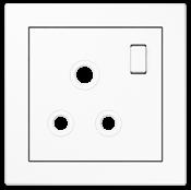
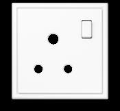
The inserts enable the flush installation into rectangular British Standard wall boxes. Combinations with other devices into multiple frames are NOT possible.
Full plate for socket insert ref.-no. BS 2171-15 EINS with integrated frame in the shape of LS 990 Duroplastic (scratch-proof) glossy

Full plate for socket insert ref.-no. BS 2171-15 EINS including British Standard 1-gang frame ref.-no. BS 2181 .. Thermoplastic (breakproof) lacquered

Socket insert British Standard 546 for rectangular British Standard wall boxes Screw terminals for wires up to 4 mm2 2-pole, 5 A 250 V ~
The inserts enable the flush installation into rectangular British Standard wall boxes. Combinations with other devices into multiple frames are NOT possible.
Centre plates for A 550 / A FLOW
Centre plate for socket insert ref.-no. BS 2171-5 EINS only in combination with frames ref.-no. A 5581 .., AF 581 ..
Duroplastic (scratch-proof) glossy
Duroplastic
Thermoplastic (breakproof) high-gloss
Centre plates for LS DESIGN (special BS frame)
Centre plate for socket insert ref.-no. BS 2171-5 EINS only in combination with frames ref.-no. BS 2181 ..
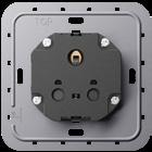
Duroplastic (scratch-proof) glossy

Ref.-no.
Switched cable unit with fuse for rectangular British Standard wall boxes
1-gang with indicator light Screw terminals for wires up to 4 mm2 2-pole, 13 A 250 V ~
BS 2190 CU KO EINS
The inserts enable the flush installation into rectangular British Standard wall boxes. Combinations with other devices into multiple frames are NOT possible.
Centre plates for A 550 / A FLOW
Centre plate for switched cable unit ref.-no. BS 2190 CU KO EINS only in combination with frames ref.-no. A 5581 .., AF 581 ..
ivory
white
Centre plates for LS DESIGN (special BS frame)
Centre plate for switched cable unit ref.-no. BS 2190 CU KO EINS only in combination with frames ref.-no. BS 2181 ..
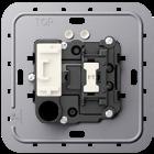
ivory (aluminium lacquered)
BS 2190 CU KO PL
white (aluminium lacquered) BS 2190 CU KO WW PL
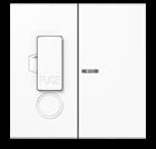
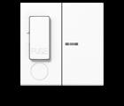
black (aluminium lacquered) BS 2190 CU KO SW PL

metal versions
aluminium
stainless steel
anthracite (aluminium lacquered)
dark (aluminium lacquered)
chrome
gold-coloured
classic brass
antique brass
BS 2190 CU KO AL PL
BS 2190 CU KO ES PL
BS 2190 CU KO AN PL
BS 2190 CU KO ALD PL
BS 2190 CU KO GCR PL
BS 2190 CU KO GO PL
BS 2190 CU KO MEC PL
BS 2190 CU KO MEAT PL
Switched socket insert, type G + I
13 A 250 V ~ for rectangular British Standard wall boxes for plugs BS 1363 (type G) and GB 2099-1 (type I) with enhanced contact protection (shutter) Screw terminals for wires up to 4 mm2
The inserts enable the flush installation into rectangular British Standard wall boxes. Combinations with other devices into multiple frames are NOT possible.
Centre plate for socket insert ref.-no. GI 2171 SW EINS only in combination with frames ref.-no. BS 2181 ..
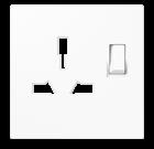
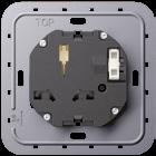

Duroplastic (scratch-proof) glossy
white
black
matt lacquered
Ref.-no.
ivory LS
matt snow white LS
matt graphite black LS
other colours on request
Ref.-no.

Frames A 550
Only in combination with new British Standard inserts (supporting frame with special holes) and British Standard centre plates of the A range (ref.-no.: A 3171 .. PL, A 3521 .. PL, A 3190 CU KO .. PL, A 2172 .. PL).

Frame, 1-gang for inserts ref.-no. BS 2171..EINS, BS 2521 EINS, BS 2190 CU KO EINS
Frame, 2-gang without crossbar for socket inserts ref.-no. BS 2172 EINS, BS 2172 KO EINS

Frames A FLOW
Installation for British Standard wall boxes
Ref.-no.


85 x 85 mm AF 581 BF ANM
white 2-gang 85 x 156 mm L AF 582-0 BF WW black 2-gang 85 x 156 mm L AF 582-0 BF SW aluminium 2-gang 85 x 156 mm P L AF 582-0 BF AL matt snow white 2-gang 85 x 156 mm AF 582-0 BF WWM matt graphite black 2-gang 85 x 156 mm AF 582-0 BF SWM matt anthracite 2-gang 85 x 156 mm AF 582-0 BF ANM
Frames LS DESIGN (special BS frames)
Frames suitable for British products (use compatible supporting frame)

Frame, 1-gang for British products (with supporting frame 80 x 80)

(breakproof) high-gloss
Frame, 2-gang for socket inserts ref.-no. BS 2172 EINS, BS 2172 KO EINS, BS 2522 EINS
Thermoplastic (breakproof) high-gloss
1-gang switch British Standard 2-pole, 45 A 250 V ~ screw terminals for wires up to 6 mm2 for rectangular British Standard wall boxes no frame required
The inserts enable the flush installation into rectangular British Standard wall boxes. Combinations with other devices into multiple frames are NOT possible.
Adapter frame
The frame enables the installtion of various JUNG inserts into BS wall boxes.

The proven standard when it comes to form and function: In addition to the harmonious lines of the AS range, the diffraction of the rocker surface creates a slight optical accent. The bright colours of white and ivory underline the stringent design.
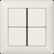
The wide product palette of the AS range completely meets the requirements of private and commercial construction; thanks to an antibacterial material finish, it also meets the special hygiene requirements, e.g. in clinics. The comprehensive range of applications includes all the technical possibilities of a modern, future-proof electrical installation.
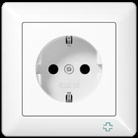

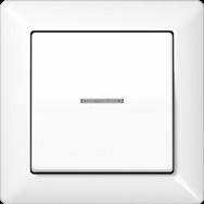 “Antibacterial” rotary dimmer in ivory
SCHUKO® socket “antibacterial” in white
Push-button with lens in white
Push-button sensor, 4-gang, in ivory
In addition to the AS 500 in Duroplastic, the unbreakable AS 500 in thermoplastic is available as an alternative. In the same design and with the same selection of colours, but made of unbreakable material, it provides, among other things, a splash-proof IP 44 version.
Duroplastic (scratch-proof), glossy
ivory similar to RAL 1013
white similar to RAL 9016
Thermoplastic (breakproof) high-gloss
ivory similar to RAL 1013
white similar to RAL 9016


Duroplastic, antibacterial
ivory similar to RAL 1013
white similar to RAL 9010
Selected items are also available in other colours
blue similar to RAL 5013
green similar to RAL 6029
orange similar to RAL 2004
red similar to RAL 3003
black ähnlich RAL 9005
Ref.-no.
1-gang rocker for switch insert ref.-no.: 501 U, 502 U, 503 U, 506 U, 507 U, 501-20 U, 506-20 U, 507-20 U for push switch insert ref.-no.: 502 TU, 506 TU, 507 TU for push-button insert ref.-no.: 531 U, 532 U, 533 U, 533-2 U
Duroplastic (scratch-proof) glossy
Thermoplastic (breakproof) high-gloss
Duroplastic (scratch-proof) glossy – antibacterial
1-gang rocker with screw fixing for switch insert ref.-no.: 501 U, 502 U, 503 U, 506 U, 507 U, 501-20 U, 506-20 U, 507-20 U for push switch insert ref.-no.: 502 TU, 506 TU, 507 TU for push-button insert ref.-no.: 531 U, 532 U, 533 U, 533-2 U
Thermoplastic (breakproof) high-gloss ivory
AS 591 BFS white
AS 591 BFS WW
For illuminated inserts use rocker with lens ref.-no.: ..KO..

1-gang rocker with lens for switch insert with indicator light ref.-no.: 502 KOU, 503 KOU, 506 KOU, 501-20 KOU, 502-20 KOU, 506-20 KOU for push switch insert with indicator light ref.-no.: 502 KOTU, 506 KOTU for push-button insert ref.-no.: 531 U, 533 U, 533-2 U, 534 U Duroplastic (scratch-proof) glossy
Thermoplastic (breakproof) high-gloss
Duroplastic (scratch-proof) glossy – antibacterial
1-gang rocker with lens and screw fixing for switch insert with indicator light ref.-no.: 502 KOU, 503 KOU, 506 KOU, 501-20 KOU, 502-20 KOU, 506-20 KOU for push switch insert with indicator light ref.-no.: 502 KOTU, 506 KOTU for push-button insert ref.-no.: 531 U, 533 U, 533-2 U, 534 U
Thermoplastic (breakproof) high-gloss
ivory
white
591 KO5BFS
591 KO5BFS WW
1-gang rocker with symbol "light" for switch insert ref.-no.: 501 U, 502 U, 503 U, 506 U, 507 U, 501-20 U, 506-20 U, 507-20 U for push switch insert ref.-no.: 502 TU, 506 TU, 507 TU for push-button insert ref.-no.: 531 U, 532 U, 533 U, 533-2 U
Duroplastic (scratch-proof) glossy
ivory
white
Duroplastic (scratch-proof) glossy – antibacterial
ivory
white


AS 591 L
AS 591 L WW

Ref.-no.
1-gang rocker with symbol "light", with lens for switch insert with indicator light ref.-no.: 502 KOU, 503 KOU, 506 KOU, 501-20 KOU, 502-20 KOU, 506-20 KOU for push switch insert with indicator light ref.-no.: 502 KOTU, 506 KOTU for push-button insert ref.-no.: 531 U, 533 U, 533-2 U, 534 U
Duroplastic (scratch-proof) glossy
ivory
white
Duroplastic (scratch-proof) glossy – antibacterial
ivory
white
1-gang rocker with symbol "bell" for push-button insert ref.-no.: 531 U, 532 U, 533 U, 533-2 U
Duroplastic (scratch-proof) glossy
ivory
IP AS 591 KO5L
IP AS 591 KO5L WW
IP ABAS 591 KO5L
IP ABAS 591 KO5L WW
IP AS 591 K
white IP AS 591 K WW
Duroplastic (scratch-proof) glossy – antibacterial
ivory IP ABAS 591 K
white IP ABAS 591 K WW
1-gang rocker with symbol "bell", with lens for push-button insert ref.-no.: 531 U, 533 U, 533-2 U, 534 U
Duroplastic (scratch-proof) glossy
ivory
white
Duroplastic (scratch-proof) glossy – antibacterial
ivory
white
1-gang rocker with symbol "door" for push-button insert ref.-no.: 531 U, 532 U, 533 U, 533-2 U
Duroplastic (scratch-proof) glossy
ivory
white
Duroplastic (scratch-proof) glossy – antibacterial
ivory
white
1-gang rocker with symbol "door", with lens for push-button insert ref.-no.: 531 U, 533 U, 533-2 U, 534 U
Duroplastic (scratch-proof) glossy
ivory
white
Duroplastic (scratch-proof) glossy – antibacterial
IP AS 591 KO5K
IP AS 591 KO5K WW
IP ABAS 591 KO5K
IP ABAS 591 KO5K WW
IP AS 591 T
IP AS 591 T WW

IP ABAS 591 T
IP ABAS 591 T WW
IP AS 591 KO5T
IP AS 591 KO5T WW
ivory IP ABAS 591 KO5T
white IP ABAS 591 KO5T WW
Barrier-free living
1-gang rocker with tactile symbol "light", with lens for switch insert with indicator light ref.-no.: 502 KOU, 503 KOU, 506 KOU, 501-20 KOU, 502-20 KOU, 506-20 KOU for push switch insert with indicator light ref.-no.: 502 KOTU, 506 KOTU for push-button insert ref.-no.: 531 U, 533 U, 533-2 U, 534 U
Duroplastic (scratch-proof) glossy
Duroplastic (scratch-proof) glossy – antibacterial
1-gang rocker with tactile symbol "bell", with lens for push-button insert ref.-no.: 531 U, 533 U, 533-2 U, 534 U

Duroplastic (scratch-proof) glossy
Duroplastic (scratch-proof) glossy – antibacterial
1-gang rocker with tactile symbol "door", with lens for push-button insert ref.-no.: 531 U, 533 U, 533-2 U, 534 U

Duroplastic (scratch-proof) glossy
Duroplastic (scratch-proof) glossy – antibacterial
For improved visibility use frame in contrasting black colour.

Ref.-no.
591 T1KO5 WW
ABAS 591 T1KO5 WW
1-gang rocker, transparent for switch insert ref.-no.: 501 U, 502 U, 503 U, 506 U, 507 U, 501-20 U, 506-20 U, 507-20 U for push switch insert ref.-no.: 502 TU, 506 TU, 507 TU for push-button insert ref.-no.: 531 U, 532 U, 533 U, 533-2 U for individual text or decorative inlets (e.g. wall paper)
Thermoplastic (breakproof) high-gloss
inscription field 50 x 50 mm
Plastic cover with paper inlay for inscription field 50 x 50 mm (Spare part)
Thermoplastic (breakproof) high-gloss paper inlay white

Holder plate for frame fixing and 1-gang rocker bearing (Spare part)

A 590 NA GL
A 590 NA GL PL
black AS 90 HP
1-gang rocker with glass plate with rocker and lens for all 1-gang switch/push-button inserts (except push switch insert) (to be used only with frame AS 581.. – AS 585..)
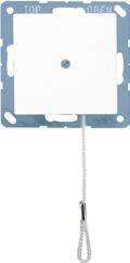
Thermoplastic (breakproof) high-gloss red similar RAL 3000
blue similar RAL 5015
yellow similar RAL 1004
for the inscription with transparent foil
Glass plate
Frame, 1-gang 80.5 x 80.5 mm

Thermoplastic (breakproof) high-gloss red similar RAL 3000


blue similar RAL 5015


similar
Pull cord switch 10 AX / 250 V ~ for wall and ceiling installation Screw terminals for wires up to 2.5 mm2 with 50 mm pull cord
Thermoplastic (breakproof) high-gloss
Other pull cord devices can be realised with pull cord insert 34 KO5 and 1-gang rocker with transparent lens AS 590 KO5 .. or AS 591 KO5 ..
2-gang rocker for switch insert ref.-no.: 505 U, 509 U for push switch insert ref.-no.: 505 TU, 509 TU for push-button insert ref.-no.: 535 U, 539 U
Duroplastic (scratch-proof) glossy
Thermoplastic (breakproof) high-gloss
Duroplastic (scratch-proof) glossy – antibacterial
2-gang rocker with lens for switch insert ref.-no.: 505 U 5 for switch insert with indicator light ref.-no.: 505 KOU 5 for push-button insert ref.-no.: 535 U 5
Duroplastic (scratch-proof) glossy
Thermoplastic (breakproof) high-gloss
Duroplastic (scratch-proof) glossy – antibacterial
2-gang rocker with arrow symbols for blind switch insert ref.-no.: 509 VU for blind push-button insert ref.-no.: 539 VU
Duroplastic (scratch-proof) glossy
Thermoplastic (breakproof) high-gloss
Ref.-no.
591-5 KO5
591-5 KO5 WW
591-5 KO5BF
591-5 KO5BF
591-5
591-5
591-5 PBF
591-5 PBF WW Duroplastic (scratch-proof) glossy – antibacterial

591-5
Holder plate for frame fixing and 2-gang rocker bearing (Spare part) black
90-5 HP
Centre plate for key switch inserts ref.-no.: 104.28, 134.18, 134.28, 133.18, 138.18, 106.28 for key switch inserts IP 44 ref.-no.: CD 104.18 WU, CD 134.18 WU, CD 133.18 WU, CD 106.18 WU
Thermoplastic (breakproof) high-gloss
L A 528 PL
L A 528 PL WW
One escutcheon plate with symbols and one without symbols included in delivery. Height of escutcheon plate: 11 mm

Centre plate for key switch inserts ref.-no.: 104.15, 134.15, 133.15, 106.15


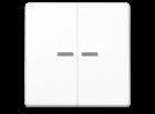
Thermoplastic (breakproof) high-gloss
525 PL
A 525 PL WW
Centre plate with knob for rotary switch insert ref.-no.: 1101-4, 1101-20 for timer switch insert ref.-no.: 11015, 11120-20 for rotary blind switch insert ref.-no.: 1234.10, 1234.20

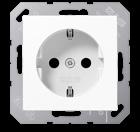
Duroplastic (scratch-proof) glossy
also for volume control WHD type: LST..JU UP and LR..JU UP and for program selection WHD type: PRO 3 JU..

SCHUKO® socket 16 A / 250 V ~
Screwless terminals for wires up to 2.5 mm2
Without claws: ref.-no. with additional "N", e.g.: ..1520 N..
With screw terminals: ref.-no. ..1521..
Supporting frame, claws and claw screws are integrated into the earth protection.
Duroplastic (scratch-proof) glossy
Thermoplastic (breakproof) high-gloss
Duroplastic (scratch-proof) glossy – antibacterial
Thermoplastic (breakproof) high-gloss – antibacterial
SCHUKO® socket 16 A / 250 V ~
with enhanced contact protection (shutter)
Screwless terminals for wires up to 2.5 mm2
With screw terminals: ref.-no. ..1521..
Supporting frame, claws and claw screws are integrated into the earth protection.
Duroplastic (scratch-proof) glossy
ivory P A 1520 KI
white P A 1520 KI WW
Thermoplastic (breakproof) high-gloss
ivory L A 1520 BFKI
white
red
Duroplastic (scratch-proof) glossy – antibacterial
ivory
white
Thermoplastic (breakproof) high-gloss – antibacterial
green
SCHUKO® socket 16 A / 250 V ~
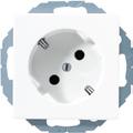
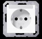

Screw terminals for wires up to 2.5 mm2
Supporting frame, claws and claw screws are integrated into the earth protection.
Duroplastic (scratch-proof) glossy
Thermoplastic (breakproof) high-gloss
SCHUKO® socket 16 A / 250 V ~ with inscription field 6 x 46 mm
Screwless terminals for wires up to 2.5 mm2
Without claws: ref.-no. with additional "N", e.g.: ..1520 N.. With screw terminals: ref.-no. ..1521..
Supporting frame, claws and claw screws are integrated into the earth protection.
Thermoplastic (breakproof) high-gloss

SCHUKO® socket 16 A / 250 V ~ with enhanced contact protection (shutter) with inscription field 6 x 46 mm
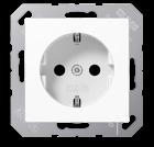
Screwless terminals for wires up to 2.5 mm2
Without claws: ref.-no. with additional "N", e.g.: ..1520 N.. With screw terminals: ref.-no. ..1521..
Supporting frame, claws and claw screws are integrated into the earth protection. Thermoplastic (breakproof) high-gloss white
Transparent cover with paper inlay for inscription field 6 x 46 mm (Spare part)
SCHUKO® socket 45°, 16 A / 250 V ~ with enhanced contact protection (shutter) Screwless terminals for wires up to 2.5 mm2 especially suitable for vertical combination of several outlets Without claws: ref.-no. with additional "N", e.g.: ..520-45 N..
Duroplastic (scratch-proof) glossy
SCHUKO® socket 16 A / 250 V ~
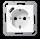
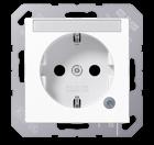
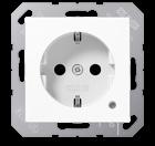
with pilot light (green LED) ref.-no.: 193-LED GN with enhanced contact protection (shutter)
Screwless terminals for wires up to 2.5 mm2
Without claws: ref.-no. with additional "N", e.g.: ..1520 N..
Supporting frame, claws and claw screws are integrated into the earth protection.
Thermoplastic (breakproof) high-gloss
Duroplastic (scratch-proof) glossy – antibacterial
Thermoplastic (breakproof) high-gloss – antibacterial
Spare pilot light exchangeable from the front without disconnecting the mains
SCHUKO® socket 16 A / 250 V ~ with pilot light (green LED) ref.-no.: 193-LED GN with enhanced contact protection (shutter) with inscription field 6 x 46 mm
Screwless terminals for wires up to 2.5 mm2
Without claws: ref.-no. with additional "N", e.g.: ..1520 N..
Supporting frame, claws and claw screws are integrated into the earth protection.
Thermoplastic (breakproof) high-gloss
Thermoplastic (breakproof) high-gloss – antibacterial

Spare pilot light exchangeable from the front without disconnecting the mains
Transparent cover with paper inlay for inscription field 6 x 46 mm (Spare part)
paper inlay white
SCHUKO® socket with USB charger with enhanced contact protection (shutter) with 1 USB port type A with quick charge function
Screwless terminals for wires up to 2.5 mm2
Installation in flush box according to EN 60670-1
Installation depth: 48 mm
Thermoplastic (breakproof) high-gloss
SCHUKO® socket with USB charger with enhanced contact protection (shutter) with 1 USB port type C with quick charge function
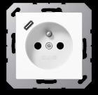
Screwless terminals for wires up to 2.5 mm2
Installation in flush box according to EN 60670-1
Installation depth: 48 mm
Thermoplastic (breakproof) high-gloss
SCHUKO® socket with USB charger with enhanced contact protection (shutter) with 1 USB port type A and 1 USB port type C


Screwless terminals for wires up to 2.5 mm2
Installation in flush box according to EN 60670-1
Installation depth: 48 mm
Thermoplastic (breakproof) high-gloss
Socket, French/Belgian system with USB charger
2-pole + male earth pin, 16 A / 250 V ~ with enhanced contact protection (shutter) with 1 USB port type A with quick charge function
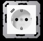
Screwless terminals for wires up to 2.5 mm2
Installation in flush box according to EN 60670-1
Installation depth: 48 mm
Thermoplastic (breakproof) high-gloss
Socket, French/Belgian system with USB charger
2-pole + male earth pin, 16 A / 250 V ~ with enhanced contact protection (shutter) with 1 USB port type C with quick charge function
Screwless terminals for wires up to 2.5 mm2
Installation in flush box according to EN 60670-1
Installation depth: 48 mm
Thermoplastic (breakproof) high-gloss
Socket, French/Belgian system with USB charger
2-pole + male earth pin, 16 A / 250 V ~ with enhanced contact protection (shutter) with 1 USB port type A and 1 USB port type C
Screwless terminals for wires up to 2.5 mm2

Installation in flush box according to EN 60670-1
Installation depth: 48 mm
Thermoplastic (breakproof) high-gloss

Ref.-no.
SCHUKO® socket 16 A / 250 V ~ with surge voltage protection
Screw terminals for wires up to 2.5 mm2
Without claws: ref.-no. with additional "N", e.g.: ..521 N..
Duroplastic (scratch-proof) glossy
ivory A 521 UF
white
A 521 UF WW
SCHUKO® socket with RCD (residual current device) 16 A / 250 V ~ according to DIN EN 61008-1 (VDE 0664-10) and DIN EN 61008-2-1 (VDE 0664-11)


Rated residual current: 30 mA with enhanced contact protection (shutter)
Screwless terminals for wires up to 2.5 mm2 not suitable for installation in surface caps
The SCHUKO socket with RCD is suitable to replace sockets in older installations. Sockets that are connected to the RCD-protected output terminals (L’ N’) are likewise RCD-protected. The electrical installation up to the SCHUKO® socket with RCD is not protected. The socket can also be switched on and off manually, using the built-in switch.
Thermoplastic (breakproof) high-gloss
ivory
white
Technical data
Rated voltage:
AC 230 V ~, 50/60 Hz
Rated current: 16 A
Rated residual current: 30 mA
Ambient temperature: −25 ... +40 °C
A 5520.30
A 5520.30 WW
RCD (residual current device) 16 A / 250 V ~ according to DIN EN 61008-1 (VDE 0664-10) and DIN EN 61008-2-1 (VDE 0664-11)
Rated residual current: 30 mA
Screwless terminals for wires up to 2.5 mm2 not suitable for installation in surface caps suitable for cables with 2 or 3 conductors
Installation into flush box with a depth of 60 mm is recommended. Protection device with voltage-independent function. The sockets connected to the output terminals are protected acc. to DIN VDE 0100-410. The electrical installation up to the RCD is not protected!
Thermoplastic (breakproof) high-gloss
ivory A 5530 FIB
white
Technical data
Rated voltage:
AC 230 V ~, 50/60 Hz
Rated current: 16 A

Rated residual current: 30 mA
Ambient temperature: −25 ... +40 °C
SCHUKO® socket 16 A / 250 V ~ with LED floor pilot light with integrated brightness sensor with enhanced contact protection (shutter)
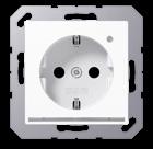
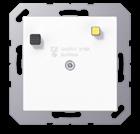
Screwless terminals for wires up to 2.5 mm2
Installation into flush box min. 63 mm (depth) with white LEDs (colour temperature 4000 K)
Power consumption stand-by / ON: 0.3 / 0.5 W
Supporting frame, claws and claw screws are integrated into the earth protection. Thermoplastic (breakproof) high-gloss
ivory
white
A 5530 FIB WW
A 1520-O LNW
A 1520-O WW LNW
LED floor pilot light with integrated brightness sensor
Screwless terminals for wires up to 2.5 mm2
Installation into flush box min. 63 mm (depth) with white LEDs (colour temperature 4000 K)
Power consumption stand-by / ON: 0.3 / 0.5 W

Supporting frame, claws and claw screws are integrated into the earth protection.
Thermoplastic (breakproof) high-gloss
LED floor pilot light

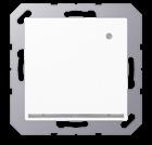
Screwless terminals for wires up to 2.5 mm2
Installation into flush box min. 63 mm (depth) with white LEDs (colour temperature 4000 K)
Power consumption (ON): 0.5 W
The floor pilot light can be switched via an external switch.
Supporting frame, claws and claw screws are integrated into the earth protection.
Thermoplastic (breakproof) high-gloss
SCHUKO® socket 16 A / 250 V ~ with hinged lid (with spring)
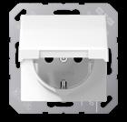
Screwless terminals for wires up to 2.5 mm2 Without claws: ref.-no. with additional "N", e.g.: ..1520 N.. With screw terminals: ref.-no. ..1521..
Supporting frame, claws and claw screws are integrated into the earth protection.
Duroplastic (scratch-proof) glossy
Thermoplastic (breakproof) high-gloss
Duroplastic (scratch-proof) glossy – antibacterial
(breakproof) high-gloss – antibacterial
SCHUKO® socket 16 A / 250 V ~ with hinged lid (with spring) with enhanced contact protection (shutter)
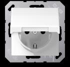

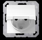
Screwless terminals for wires up to 2.5 mm2
Without claws: ref.-no. with additional "N", e.g.: ..1520 N..
With screw terminals: ref.-no. ..1521..
Supporting frame, claws and claw screws are integrated into the earth protection.
Duroplastic (scratch-proof) glossy
Thermoplastic (breakproof) high-gloss
Duroplastic (scratch-proof) glossy – antibacterial
Thermoplastic (breakproof) high-gloss – antibacterial

SCHUKO® socket 16 A / 250 V ~ with hinged lid (with spring)
Screw terminals for wires up to 2.5 mm2
Supporting frame, claws and claw screws are integrated into the earth protection.
Duroplastic (scratch-proof) glossy
Thermoplastic (breakproof) high-gloss
SCHUKO® socket 16 A / 250 V ~ with hinged lid (with spring) with enhanced contact protection (shutter) Screw terminals for wires up to 2.5 mm2
Supporting frame, claws and claw screws are integrated into the earth protection.
Duroplastic (scratch-proof) glossy
Thermoplastic (breakproof) high-gloss
SCHUKO® socket 16 A / 250 V ~ with hinged lid (with spring) with pilot light (green LED) ref.-no.: 193-LED GN with enhanced contact protection (shutter)
Screwless terminals for wires up to 2.5 mm2 Without claws: ref.-no. with additional "N", e.g.: ..1520 N..
Supporting frame, claws and claw screws are integrated into the earth protection.
Thermoplastic (breakproof) high-gloss
Duroplastic (scratch-proof) glossy – antibacterial
Thermoplastic (breakproof) high-gloss – antibacterial

Spare pilot light exchangeable from the front without disconnecting the mains
SCHUKO® socket 16 A / 250 V ~ with hinged lid (with spring) with safety lock (24 different locks) with enhanced contact protection (shutter)

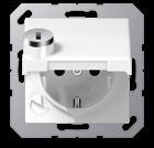
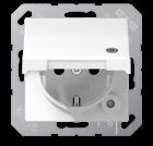
Screwless terminals for wires up to 2.5 mm2 Without claws: ref.-no. with additional "N", e.g.: ..1520 N.. With screw terminals: ref.-no. ..1521..
Supporting frame, claws and claw screws are integrated into the earth protection.
Thermoplastic (breakproof) high-gloss
Key (Spare part) for all hinged lids with safety lock
When ordering, please indicate lock number! 1
Socket, 2-pole without earth 16 A / 250 V ~ Screw terminals for wires up to 2.5 mm2
Duroplastic (scratch-proof) glossy
Socket, 2-pole without earth 16 A / 250 V ~ with enhanced contact protection (shutter)
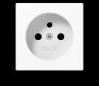

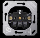
Screw terminals for wires up to 2.5 mm2
Duroplastic (scratch-proof) glossy
ivory
white
Socket for Switzerland
1-gang socket type 13
10 A 250 V ~, L + N + PE
Ref.-no.
P A 511 NKI
P A 511 NKI WW
Screwless terminals for wires up to 2.5 mm2 acc. to SEV 1011-1998/IEC 884-1

Installation in flush box according to EN 60670-1 not suitable for installation in surface caps with supporting frame, screw fixing only
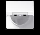
Thermoplastic (breakproof) high-gloss
ivory
L A 1520-13 BF SEV
white L A 1520-13 BF SEV WW
Socket insert, French/Belgian system
2-pole + male earth pin, 16 A / 250 V ~
Supporting frame, claws and claw screws are integrated into the earth protection. with claws
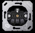
Socket insert, French/Belgian system
2-pole + male earth pin, 16 A / 250 V ~
Supporting frame is integrated into the earth protection. without claws
Centre plate for socket insert French/Belgian system, ref.-no.: 1520 ..F EINS, 1521 ..F EINS
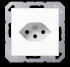
Duroplastic (scratch-proof) glossy
Centre plate for socket insert French/Belgian system, ref.-no.: 1520 ..F EINS, 1521 ..F EINS with enhanced contact protection (shutter)
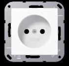
Duroplastic (scratch-proof) glossy ivory
Centre plate with hinged lid (with spring) for socket insert French/Belgian system, ref.-no.: 1520 ..F EINS, 1521 ..F EINS with enhanced contact protection (shutter)
Duroplastic (scratch-proof) glossy ivory
Ref.-no.
Socket US NEMA system
15 A, 125 V ~, 5-15R, 2-pole + earth
Screw terminals for wires up to 4 mm2 acc. to US-NEMA
Thermoplastic (breakproof) high-gloss
ivory A 521-15
white A 521-15 WW
Socket US NEMA system
20 A, 125 V ~, 5-20R, 2-pole + earth
Screw terminals for wires up to 4 mm2 acc. to US-NEMA
Thermoplastic (breakproof) high-gloss
ivory A 521-20
white A 521-20 WW
Socket insert British Standard 1363
13 A 250 V ~
2-pole + earth, with enhanced contact protection (shutter)
Screw terminals for wires up to 4 mm2 without switch
Centre plate for socket insert ref.-no. 3521 EINS
Duroplastic (scratch-proof) glossy
ivory
white
Switched socket insert British Standard 1363
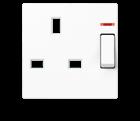

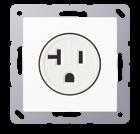

13 A 250 V ~
2-pole + earth, with enhanced contact protection (shutter) Screw terminals for wires up to 4 mm2 without indicator light

3521 EINS
A 3521 PL
A 3521 WW PL
3171 EINS with indicator light
3171 KO EINS
Centre plate for socket insert ref.-no. 3171 EINS
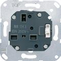

Duroplastic (scratch-proof) glossy
ivory
white
Centre plate for socket insert ref.-no. 3171 KO EINS
Duroplastic (scratch-proof) glossy
ivory
white
A 3171 PL
A 3171 WW PL
A 3171 KO PL
A 3171 KO WW PL
Socket insert British Standard 546
5 A 250 V ~
2-pole + earth, with enhanced contact protection (shutter)
Screw terminals for wires up to 4 mm2 without switch
Centre plate for socket insert ref.-no. 3171-5 EINS
Duroplastic (scratch-proof) glossy
3171-5 EINS
ivory A 3171-5 PL
white
Socket insert for China
consisting of:
2-pole without earth for flat and rounded pins and
2-pole with earth only for flat pins with enhanced contact protection (shutter)
Screw terminals for wires up to 4 mm2
screw fixing only, without claws
Supporting frame is integrated into the earth protection. without switch 3521-5 CN EINS

Centre plate for Chinese socket combination, ref.-no. 3521-5 CN EINS

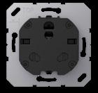
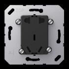

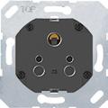
Duroplastic (scratch-proof) glossy ivory
Thermoplastic (breakproof) high-gloss
white
Socket insert for India
16 A 250 V ~
2-pole + earth, with enhanced contact protection (shutter)
Screw terminals for wires up to 4 mm2 without switch 521 IN-EINS
Centre plate for socket insert for India, ref.-no. 521 IN-EINS
Duroplastic (scratch-proof) glossy
Ref.-no.
Switched cable unit with fuse 2-pole, 13 A 250 V ~ with indicator light
Screw terminals for wires up to 4 mm2
3190 CU KO EINS
Centre plate for switched cable unit ref.-no. 3190 CU KO EINS

ivory A 3190 CU KO PL
white A 3190 CU KO WW PL
SCHUKO® socket 16 A / 250 V ~ with 1-gang / 2-way switch 10 AX / 250 V ~ to be installed into one flush box with 60 mm Ø Screw terminals for wires up to 2.5 mm2

Without claws: ref.-no. with additional "E", e.g.: AS 5576 EU

dimensions: 80.5 x 105 mm
Duroplastic (scratch-proof) glossy
ivory AS 5576 U
white AS 5576 U WW
(2-way switch circuit possible with ref.-no. 506 U or 506 TU.)
SCHUKO® socket 16 A / 250 V ~ with 2-gang switch 10 AX / 250 V ~ to be installed into one flush box with 60 mm Ø
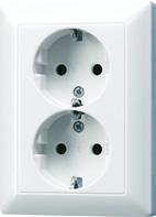
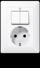
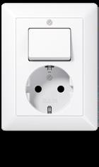
Screw terminals for wires up to 2.5 mm2 screw fixing only, without claws
dimensions: 80.5 x 105 mm
Duroplastic (scratch-proof) glossy
ivory AS 5575 EU
white AS 5575 EU WW
2-gang SCHUKO® socket 16 A / 250 V ~ to be installed into one flush box with 60 mm Ø
Screwless terminals for wires up to 2.5 mm2
Without claws: ref.-no. with additional "N", e.g.: ..1520 N..
dimensions: 80.5 x 105 mm
Duroplastic (scratch-proof) glossy
ivory
AS 5020 U
white AS 5020 U WW
Ref.-no.
2-gang SCHUKO® socket 16 A / 250 V ~ with enhanced contact protection (shutter) to be installed into one flush box with 60 mm Ø
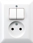
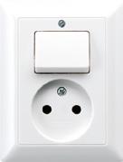
Screwless terminals for wires up to 2.5 mm2
Without claws: ref.-no. with additional "N", e.g.: ..1520 N..
dimensions: 80.5 x 105 mm
Duroplastic (scratch-proof) glossy
ivory AS 5020 KIU
white AS 5020 KIU WW
2-gang SCHUKO® socket 16 A / 250 V ~ to be installed into one flush box with 60 mm Ø
Screw terminals for wires up to 2.5 mm2
dimensions: 80.5 x 105 mm
Duroplastic (scratch-proof) glossy
ivory AS 5022 U
white
AS 5022 U WW with enhanced contact protection (shutter)
Duroplastic (scratch-proof) glossy
ivory AS 5022 KIU
white AS 5022 KIU WW
Socket, 2-pole without earth 16 A / 250 V ~ with 1-gang/2-way switch 10 AX / 250 V ~ to be installed into one flush box with 60 mm Ø


Screw terminals for wires up to 2.5 mm2
dimensions: 80.5 x 105 mm
Duroplastic (scratch-proof) glossy
ivory AS 5546 EU
white AS 5546 EU WW
(2-way switch circuit possible with ref.-no. 506 U or 506 TU.)
Socket, 2-pole without earth 16 A / 250 V ~ with 2-gang switch 10 AX / 250 V ~ to be installed into one flush box with 60 mm Ø
Screw terminals for wires up to 2.5 mm2 dimensions: 80.5 x 105 mm

Duroplastic (scratch-proof) glossy
ivory AS 5545 EU
white AS 5545 EU WW
2-gang socket, 2-pole without earth 16 A / 250 V ~ to be installed into one flush box with 60 mm Ø
Screwless terminals for wires up to 2.5 mm2
Duroplastic (scratch-proof) glossy
ivory AS 5010 U
white AS 5010 U WW with enhanced contact protection (shutter)
Duroplastic (scratch-proof) glossy
ivory AS 5010 KIU
white AS 5010 KIU WW
Ref.-no.


SCHUKO® socket for cable ducts 16 A / 250 V ~ wired Screwless terminals for wires up to 2.5 mm2 Cover with integrated frame for installation into cable duct boxes Supporting frame is integrated into the earth protection.

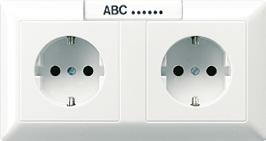
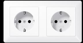
dimensions: 80.5 x 151.5 mm
2-gang
Duroplastic (scratch-proof) glossy
ivory AS 1522
white AS 1522 WW
Thermoplastic (breakproof) high-gloss
ivory AS 1522 BF
white AS 1522 BF WW
with 1 inscription field 12 x 55.5 mm
2-gang
Duroplastic (scratch-proof) glossy
ivory AS 1522 NA
white AS 1522 NA WW
SCHUKO® socket for cable ducts 16 A / 250 V ~ Screwless terminals for wires up to 2.5 mm2 Cover with integrated frame for installation into cable duct boxes
dimensions: 80.5 x 151.5 mm
3-gang
Duroplastic (scratch-proof) glossy
ivory AS 523
white AS 523 WW
Thermoplastic (breakproof) high-gloss

ivory AS 523 BF
white AS 523 BF WW
Centre plate with knob for rotary dimmer inserts ref.-no.: 1730 DD, 1731 DD, 211 GDE for satellite dimmer insert ref.-no.: 1733 DNE for electronic potentiometer 1–10 V ref.-no.: 240-10 for DALI rotary controllers ref.-no.: 1740 DSTE, 1741 DSTE

Duroplastic (scratch-proof) glossy ivory
Sealing gasket for covers for rotary dimmer inserts
To obtain protection level IP 44 the sealing gasket ref.-no.: 140 D has to be placed into the centre plate for rotary dimmer and IP 44 frame has to be used.


Ref.-no.
Duroplastic (scratch-proof) glossy ivory
white
Rotary dimmer LED with rotary on/off with cover and integrated frame without satellite input single device, not suitable for combinations
Technical data
Rated voltage: AC 230 V ~
Mains frequency: 50 Hz
Stand-by power: approx. 0.2 W
Power loss: approx. 3.7 W
Ambient temperature: −5 ... +45 °C
Connected load at 25 °C
Incandescent lamps: 20 ... 200 W
HV halogen lamps: 20 ... 200 W
Dimmable HV LED lamps: typical 3 ... 40 W

Ohmic and HV LED: typical 3 ... 40 W
Reduction of load
Surface mounting: −5 % for every 5 °C exceededing 35 °C: −10 % for installation into wooden or hollow walls: −15 %
Fine-wire fuse: T 800 mA H 250
Connection mode: screw terminals single wire: 1 x 0.5 ... 2.5 mm2
stranded without ferrule: 1 x 0.5 ... 2.5 mm2
stranded with ferrule: 1 x 0.5 ... 2.5 mm2
2-way switch circuit: not possible
Ref.-no.
Standard centre plate for LB Management inserts "blinds" ref.-no.: 1730 JE and 1731 JE for LB Management inserts "light"


ref.-no.: 1701 SE, 1704 ESE, 1702 SE, 1710 DE, 1711 DE, 1713 DSTE, 1720 NE, 1723 NE, 1708 IE
Duroplastic (scratch-proof) glossy
ivory AS 1700
white AS 1700 WW
Standard centre plate "arrows" for LB Management inserts "blinds" ref.-no.: 1730 JE and 1731 JE for LB Management inserts "light"
ref.-no.: 1701 SE, 1704 ESE, 1702 SE, 1710 DE, 1711 DE, 1713 DSTE, 1720 NE, 1723 NE, 1708 IE
Duroplastic (scratch-proof) glossy
ivory AS 1700 P
white AS 1700 P WW
Universal centre plate for LB Management inserts "blinds" ref.-no.: 1730 JE and 1731 JE for LB Management inserts "light"
ref.-no.: 1701 SE, 1704 ESE, 1702 SE, 1710 DE, 1711 DE, 1713 DSTE, 1723 NE
Duroplastic (scratch-proof) glossy
ivory AS 1701
white AS 1701 WW
Universal centre plate "arrows" for LB Management inserts "blinds" ref.-no.: 1730 JE and 1731 JE for LB Management inserts "light"
ref.-no.: 1701 SE, 1704 ESE, 1702 SE, 1710 DE, 1711 DE, 1713 DSTE, 1723 NE
Duroplastic (scratch-proof) glossy
ivory AS 1701 P
white AS 1701 P WW
Standard centre plate 2-gang for LB Management inserts "light" ref.-no.: 1702 SE, 1712 DE, 1713 DSTE, 1723 NE

Duroplastic (scratch-proof) glossy
ivory AS 1702
white AS 1702 WW
Standard timer with display for LB Management inserts "blinds" ref.-no.: 1730 JE and 1731 JE for LB Management inserts "light"

ref.-no.: 1701 SE, 1704 ESE, 1702 SE, 1710 DE, 1711 DE, 1713 DSTE, 1723 NE
white
black
A 1750 D WW
A 1750 D SW
Ref.-no.
Universal timer Bluetooth for LB Management inserts "blinds" ref.-no.: 1730 JE and 1731 JE for LB Management inserts "light"


ref.-no.: 1701 SE, 1704 ESE, 1702 SE, 1710 DE, 1711 DE, 1713 DSTE, 1723 NE
Duroplastic (scratch-proof) glossy
ivory AS 1751 BT
white AS 1751 BT WW
Universal timer Bluetooth "arrows" for LB Management inserts "blinds" ref.-no.: 1730 JE and 1731 JE for LB Management inserts "light"
ref.-no.: 1701 SE, 1704 ESE, 1702 SE, 1710 DE, 1711 DE, 1713 DSTE, 1723 NE
Duroplastic (scratch-proof) glossy
ivory AS 1751 PBT
white AS 1751 PBT WW
eNet Standard radio centre plate for LB Management inserts "blinds" ref.-no.: 1730 JE and 1731 JE for LB Management inserts "light"
ref.-no.: 1701 SE, 1704 ESE, 1702 SE, 1710 DE, 1711 DE, 1713 DSTE, 1723 NE
Duroplastic (scratch-proof) glossy
ivory
white
eNet Standard radio centre plate "arrows" for LB Management inserts "blinds" ref.-no.: 1730 JE and 1731 JE for LB Management inserts "light"
ref.-no.: 1701 SE, 1704 ESE, 1702 SE, 1710 DE, 1711 DE, 1713 DSTE, 1723 NE
Duroplastic (scratch-proof) glossy
ivory
white
eNet radio centre plate for LB Management inserts "blinds" ref.-no.: 1730 JE and 1731 JE for LB Management inserts "light"
ref.-no.: 1701 SE, 1704 ESE, 1702 SE, 1710 DE, 1711 DE, 1713 DSTE, 1723 NE
Duroplastic (scratch-proof) glossy
ivory
white
eNet radio centre plate "arrows" for LB Management inserts "blinds" ref.-no.: 1730 JE and 1731 JE for LB Management inserts "light"
ref.-no.: 1701 SE, 1704 ESE, 1702 SE, 1710 DE, 1711 DE, 1713 DSTE, 1723 NE
Duroplastic (scratch-proof) glossy
ivory
FM AS 1700
FM AS 1700 WW
FM AS 1700 P
FM AS 1700 P WW
FM AS 1701
FM AS 1701 WW
FM AS 1701 P
white FM AS 1701 P WW

Standard automatic switch 1.1 m for LB Management inserts "light"
ref.-no.: 1701 SE, 1704 ESE, 1702 SE, 1710 DE, 1711 DE, 1713 DSTE, 1723 NE, 1708 IE
Thermoplastic (breakproof) high-gloss ivory


17180 white
17180 WW
Standard automatic switch 1.1 m for LB Management inserts "light"
ref.-no.: 1701 SE, 1704 ESE, 1702 SE, 1710 DE, 1711 DE, 1713 DSTE, 1723 NE, 1708 IE
IP 44 suitable only for indoor installation
Thermoplastic (breakproof) high-gloss
Standard automatic switch 2.2 m for LB Management inserts "light"
ref.-no.: 1701 SE, 1704 ESE, 1702 SE, 1710 DE, 1711 DE, 1713 DSTE, 1723 NE, 1708 IE
IP 44 suitable only for indoor installation
Thermoplastic (breakproof) high-gloss
Universal automatic switch 1.1 m for LB Management inserts "light"
ref.-no.: 1701 SE, 1704 ESE, 1702 SE, 1710 DE, 1711 DE, 1713 DSTE, 1723 NE, 1708 IE
Thermoplastic (breakproof) high-gloss
ivory A 17181
white A 17181 WW
Universal automatic switch 1.1 m for LB Management inserts "light"
ref.-no.: 1701 SE, 1704 ESE, 1702 SE, 1710 DE, 1711 DE, 1713 DSTE, 1723 NE, 1708 IE
IP 44 suitable only for indoor installation
Thermoplastic (breakproof) high-gloss
ivory IP A 17181 WU
white IP A 17181 WU WW
Universal automatic switch 2.2 m for LB Management inserts "light"
ref.-no.: 1701 SE, 1704 ESE, 1702 SE, 1710 DE, 1711 DE, 1713 DSTE, 1723 NE, 1708 IE
IP 44 suitable for indoor and outdoor installation

Thermoplastic (breakproof) high-gloss
ivory IP A 17281
white IP A 17281 WW
Sealing kit for automatic switches 2.2 m of the AS / A ranges
To obtain protection level IP 44


Electronic timer, 230 V~, 1500 VA
The device is operated simply by pressing the button. After a previously set time delay the timer switches off automatically. The activated time delay can be stopped by pressing the button again.
1-pole switch contact, with status LED, satellite operation possible incl. 1-gang frame with inscription field and labels for various time periods time delay 1 – 60 min.
Duroplastic (scratch-proof) glossy
time delay 1 – 8 hours
Duroplastic (scratch-proof) glossy
Timer switch 16 AX / 250 V ~ Screw terminals for wires up to 4 mm2
surface cap with inscription field
and scale disc
Thermoplastic (breakproof) high-gloss
The AeroTec timer may be used to operate sun protection systems only

Intermediate frame to install "AeroTec 04" in AS and A ranges
Room thermostat (1-way contact)

1-pole NC contact 10 (4) A, AC 230 V ~, 50/60 Hz
Thermoplastic (breakproof) high-gloss

Room thermostat (1-way contact)

1-pole NC contact 10 (4) A, AC 24 V ~
(breakproof) high-gloss
Room thermostat (2-way contact)
1-pole, 2-way, heating 10 (4) A, AC 230 V ~, 50/60 Hz
1-pole, 2-way, cooling 5 (2) A, AC 230 V ~, 50/60 Hz
For switching between heating/cooling the EBERLE terminal strip EV..H/K is necessary.
(breakproof) high-gloss
Room thermostat (2-way contact)

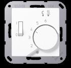
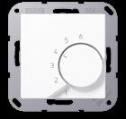

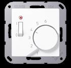
1-pole, 2-way, heating 10 (4) A, AC 24 V ~ 1-pole, 2-way, cooling 5 (2) A, AC 24 V ~

(breakproof) high-gloss
Floor thermostat 1-pole NO contact 10 A, AC 230 V ~, 50/60 Hz
Thermoplastic (breakproof) high-gloss
Special knob, manipulation-proof
The set temperature can no longer be changed after the knob has been "locked". Dismounting only possible with tool.
Humidistat
Thermoplastic (breakproof) high-gloss
Ref.-no.
Room thermostat with display standard consists of room thermostat insert (ref.-no.: 1790 RTR) and display (ref.-no.: .. 1790 D ..) white


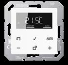
External temperature sensor for room thermostat ref.-no. 1790 RTR, TR D .. 1790 .. spare part for floor thermostat ref.-no. FTR .. 231 ..
FF 7.8
Also suitable as external temperature sensor for the following KNX devices, ref.-no.: .. 2178 TS .., .. 2178 ORTS .., .. 5192 KRM TS D, .. 5194 KRM TS D, 2177 SV R, 23066 REGHE


Technical data
NTC sensor in plastic cap 7.8 mm Ø
Cable length: 4 m

Ambient temperature: −25 ... +70 °C
Temperature controller fan coil, 2-pipe
Temperature controller fan coil, 4-pipe
Cover kits F50 see as of page 662
Cover kits F40 see as of page 671
Centre plate with supporting frame, screw fixing only for 2 loudspeaker sockets up to 18.5 mm Ø or with flange mounting 22.5 mm hole spacing. In connection with mounting plate ref.-no. 63 WBT (not included) for loudspeaker terminal ref.-no. LPK 63 RT/SW and RCA socket ref.-no. CIB 63. Second hole can be broken out.
Duroplastic (scratch-proof) glossy
Centre plate with supporting frame, screw fixing only for loudspeaker socket ref.-no.: PB 4 for chassis connector ref.-no.: CXLR-S, CXLR-D for XLR chassis Neutrik D / DL / DLX Series internal dimensions (W x H): 27.5 x 32.5 mm
Thermoplastic (breakproof) high-gloss
Centre plate for XLR socket with supporting frame, screw fixing only e.g. Binder, Cannon, Neutrik (P Series) internal dimensions (W x H): 27.5 x 37 mm
Thermoplastic (breakproof) high-gloss
Centre plate for TV-FM sockets ref.-no.: EDU 04 F, GEDU 10, GEDU 15

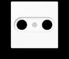
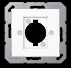
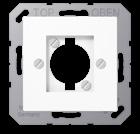
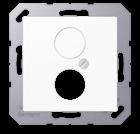

Duroplastic (scratch-proof) glossy
Thermoplastic (breakproof) high-gloss
Duroplastic (scratch-proof) glossy – antibacterial
Centre plate for SAT-TV-FM socket outlet inserts ref.-no.: EDA 302 F, GDA 313 F for standard SAT-TV-FM sockets
Duroplastic (scratch-proof) glossy
Thermoplastic (breakproof) high-gloss
Ref.-no.
Smart TV socket with supporting frame, screw fixing only
Cover with snap-on fixing and shutter with spring including universal modular jack socket ref.-no.: UMA-CAT6A and IEC plug module for antenna cables
Thermoplastic (breakproof) high-gloss
white MMD A 4521 WW
Technical data
Specification IEC plug module
External connection: coaxial plug IEC 60169-2
Internal connection: F socket IEC 60169-24
Impedance: 75 Ohm
Frequency range: 5 ... 2,400 MHz
Attenuation: 0.0 dB
Installation depth not considering cables
Universal modular jack socket: 40 mm
IEC plug module: 30 mm
Use right angle plug.
Consider bending radius. Ensure sufficient installation space.

Electronic door signal AC 8 – 12 V ~ / DC 12 – 17 V with supporting frame, screw fixing only
Thermoplastic (breakproof) high-gloss
ivory
white
Technical data
A 567 S
A 567 S WW
Loudness: approx. 82 dB(A) (sound 1, approx. 800 Hz), distance 1 m and AC 12 V ~ (Piezo, with sound generator) approx. 96 dB(A) (sound 2, approx. 3000 Hz), distance 1 m and AC 12 V ~ (Piezo, with sound generator)
Terminals: ~ 1 sound 1 (approx. 800 Hz) ~ 2 sound 2 (approx. 3,000 Hz)
Current consumption: approx. 24 mA at AC 12 V ~ approx. 12 mA at DC 12 V
Triple-tone door signal with supporting frame, screw fixing only

Thermoplastic (breakproof) high-gloss
ivory
white
2 separate terminals for 2 or 3 tone signal power supply: 8 ... 12 V AC or 8 ... 24 V DC, via external power supply (SELV)
e.g. ref.-no. NT 2405 VDC or NT 2415 REG VDC
current consumption: approx. 150 mA
Cable outlet with supporting frame, screw fixing only opening for cables with max. 8 mm Ø
Duroplastic (scratch-proof) glossy
A 567-G3
A 567-G3 WW
ivory P AS 590 A
white P AS 590 A WW

Ref.-no.
Centre plate for 1-gang modular jack sockets
IAE/UAE sockets ref.-no.: UAE 8 UPO for sockets Cat. 6 ref.-no.: UAE 8 UPOK6 (1 x 8-pol.) for WLAN access point ref.-no.: WLAN-AC-UAE, WLAN-AC-POE-UAE


Duroplastic (scratch-proof) glossy
ivory
white
Thermoplastic (breakproof) high-gloss
ivory
white
Suitable inserts:
569-1 PLUA
569-1 PLUA WW
A 569-1 BFPLUA
A 569-1 BFPLUA WW
Rutenbeck: UAE 8(4) UPO, UAE 8(8) UPO, UAE-Cat.5e-8 UPO OK, UAE-real.Cat.6-8 UPO OK
Telegärtner: AMJ 45, UMJ 45 and ISDN 1 x RJ 45 (TYP 8)
Centre plate for 2-gang modular jack sockets
IAE/UAE sockets ref.-no.: UAE 2 x 8 UPO, UAE 8-8 UPO for sockets Cat. 6 ref.-no.: UAE 8-8 UPOK6 (2 x 8-pol.)

for media converter 2-gang ref.-no.: MK-POF-2UAE

Thermoplastic (breakproof) high-gloss
ivory
L A 569-2 BFPLUA
white L A 569-2 BFPLUA WW
Suitable inserts: METZ CONNECT (BTR): 1307441001-i or 1307441200-i; E-Dat design 8/8(8), Class E
Rutenbeck: UAE 8/8 (8/8) UPO, UAE 2x8 (8) UPO, UAE-Cat.5e-8/8 UPO OK, UAE-real.Cat.6-8/8 UPO OK
Telegärtner: AMJ 45, UMJ 45 and ISDN 2 x RJ 45 (TYP 8/8)
Centre plate (screw fixing) for stereo loudspeaker socket ref.-no.: SLA 2 WW, SLA 2 AN for 2-gang supporting frame ref.-no.: UMA-MA2 in connection with universal modular jack socket type A ref.-no.: UMA-CAT6A
Duroplastic (scratch-proof) glossy
ivory P A 569 PLT
white P A 569 PLT WW
Thermoplastic (breakproof) high-gloss
ivory
L A 569 BFPLT
white L A 569 BFPLT WW
Duroplastic (scratch-proof) glossy – antibacterial
ivory ABA 569 PLT
white ABA 569 PLT WW
for Rutenbeck: UM-MA 2 Up with UM-real Cat.6a A for Dätwyler: flush-mounted modular jack socket (for 2 x MS-K 1/8 Cat.6a), ref.-no.: 440 012
Centre plate (snap-on fixing) for USB charger ref.-no.: USB 15 CA WW, USB 15 CA SW
Thermoplastic (breakproof) high-gloss
ivory
white
USB charger see page 72
L A 1569 USB
L A 1569 USB WW