KNX Catalogue


EN
Table of contents


86 F 10
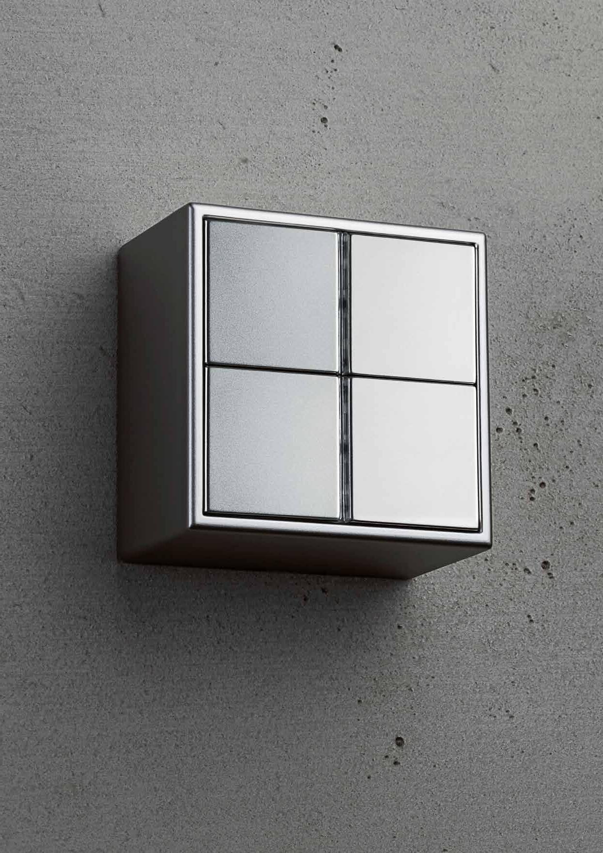
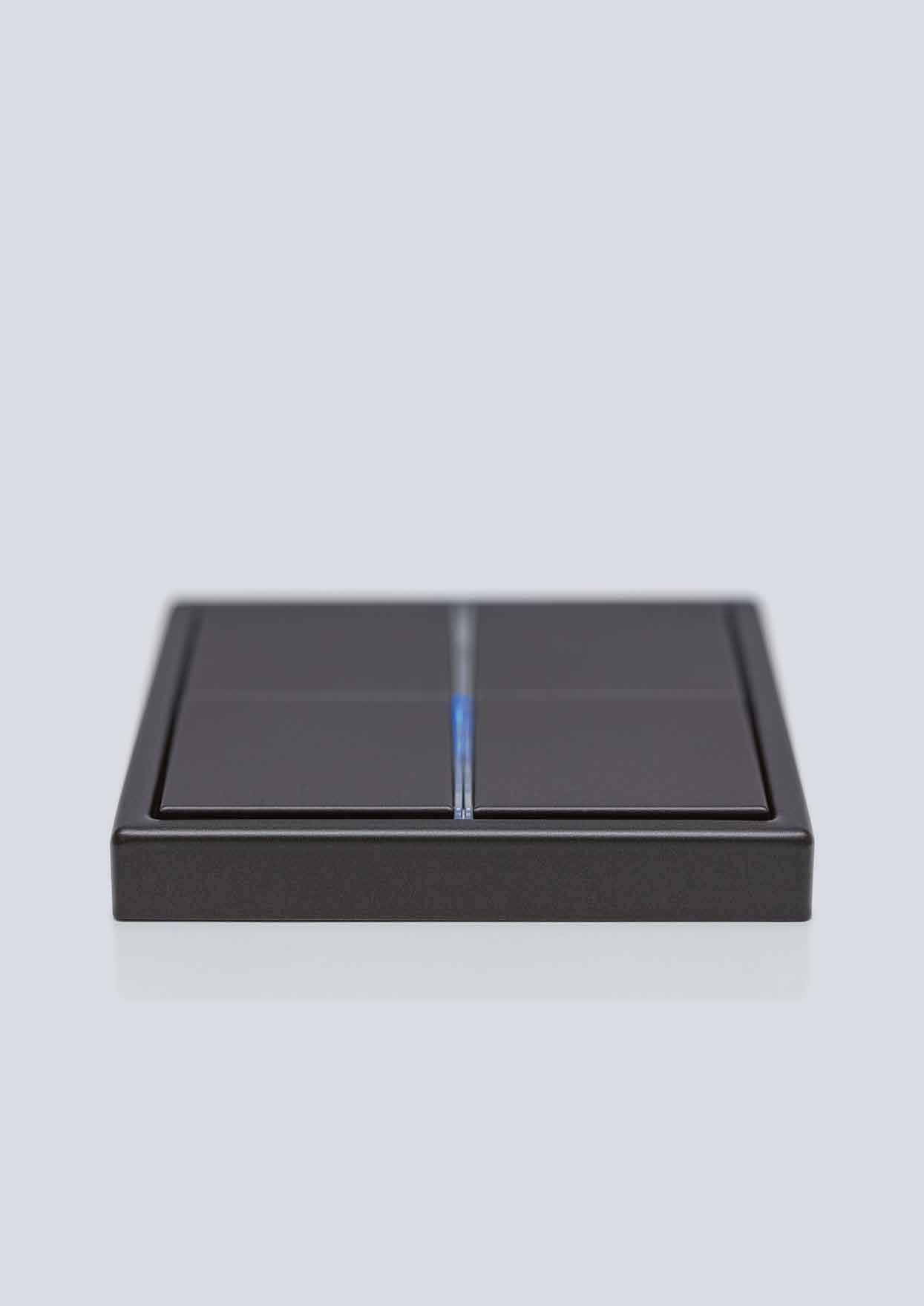
Simple design, sophisticated technology.
154 IPS REMOTE Simply efficient: Remote maintenance of the KNX system.
262 SMART VISU SERVER
SYSTEM DEVICES System design 152 COMMUNICATION/GATEWAYS SONOS gateway 168 DALI gateway 170 ACTUATORS/COMBINATION DEVICES Actuators for rail mounting 172 Multistation 210 Flush mounting actuators 222 BINARY INPUTS Binary inputs 231 ENERGY SENSOR Energy sensor 234 WEATHER STATIONS Weather stations 236 VISUALISATION/OPERATION Signal Panel 246 Smart Panel 248 Smart Controls 252 Smart Control 5 256 Smart Visu Server 262 JUNG Visu Pro 270 JUNG Visu Pro Server 278 COMPANY Progress as tradition 02 INTRODUCTION When is a building smart? 04 KNX as worldwide standard 06 Functions and applications 08 References 10 TOPOLOGY The JUNG KNX system 16 PUSH-BUTTON SENSORS/ROOM CONTROLLERS KNX Secure 18 Operating KNX in the JUNG design 22 Graphic tool 24 F 50 family 26 F 40 family 54 KNX RF 78 Room controller 78 F 10 family 86 ROTARY SENSORS/PUSH-BUTTONS BCU Push-button BCU 110 Rotary sensors 114 ROOM AUTOMATION Presence Detector Mini 120 Presence detector/Ceiling observer 126 Automatic switch 130 Room temperature controller 138
More convenience and control, even when travelling.
18
CONTENTS 1
KNX SECURE Effective protection for smart buildings.
Progress as tradition
JUNG stands for pure design and future-oriented solutions worldwide. Innovation, passion and precision have been guiding our product developments for more than 100 years. Light, shading, air conditioning, energy, security, door communication and multimedia – our systems provide the appropriate solution for every requirement.

With 1300 employees, 19 subsidiaries and independent sales and partner organisations in around 70 countries, we are represented on five continents. Whether private, commercial or hotel construction: architects and planners worldwide place their trust in the innovative solutions from JUNG. Our building technology can be found in the Reichstag in Berlin as well as in the Hermitage in St. Petersburg and the Shangri-La Hotel in Singapore.
We consciously combine this internationality with close ties to the headquarters of our family business in Schalksmühle. There and in Lünen we develop and manufacture components for classic electrical installations as well as intelligent systems for building technology. Mass production, small series or genuine manufacture: our modern production methods meet the highest requirements.
Company founder Albrecht Jung Medium-sized third generation family company
Ernst Paris WE ARE JUNG: 1912 “Made in Germany” for more than 100 years 19 subsidiaries and over 70 agencies worldwide Around 1300 employees
JUNG – PROGRESS AS TRADITION 3 2 JUNG – PROGRESS AS TRADITION
What makes a building smart?
When all the functions of modern building system technology are networked in a meaningful way and communicate with each other. This means extra comfort, cost-effectiveness, safety and energy efficiency. Our solutions are based on the KNX standard popular worldwide and are therefore absolutely future-proof. From easy to use control elements to a complex system, the JUNG KNX components provide comprehensive, future-proof solutions for control,
visualisation and organisation of the building system technology. Our systems completely cover areas such as lighting, shade, heating/air conditioning, surveillance/security, multimedia and smart metering
From the basic configuration to the high end comfort solution, everything is possible. The professional JUNG KNX technology can be adapted to new requirements at any time.
Function Visualisation System reliability
Evaluation
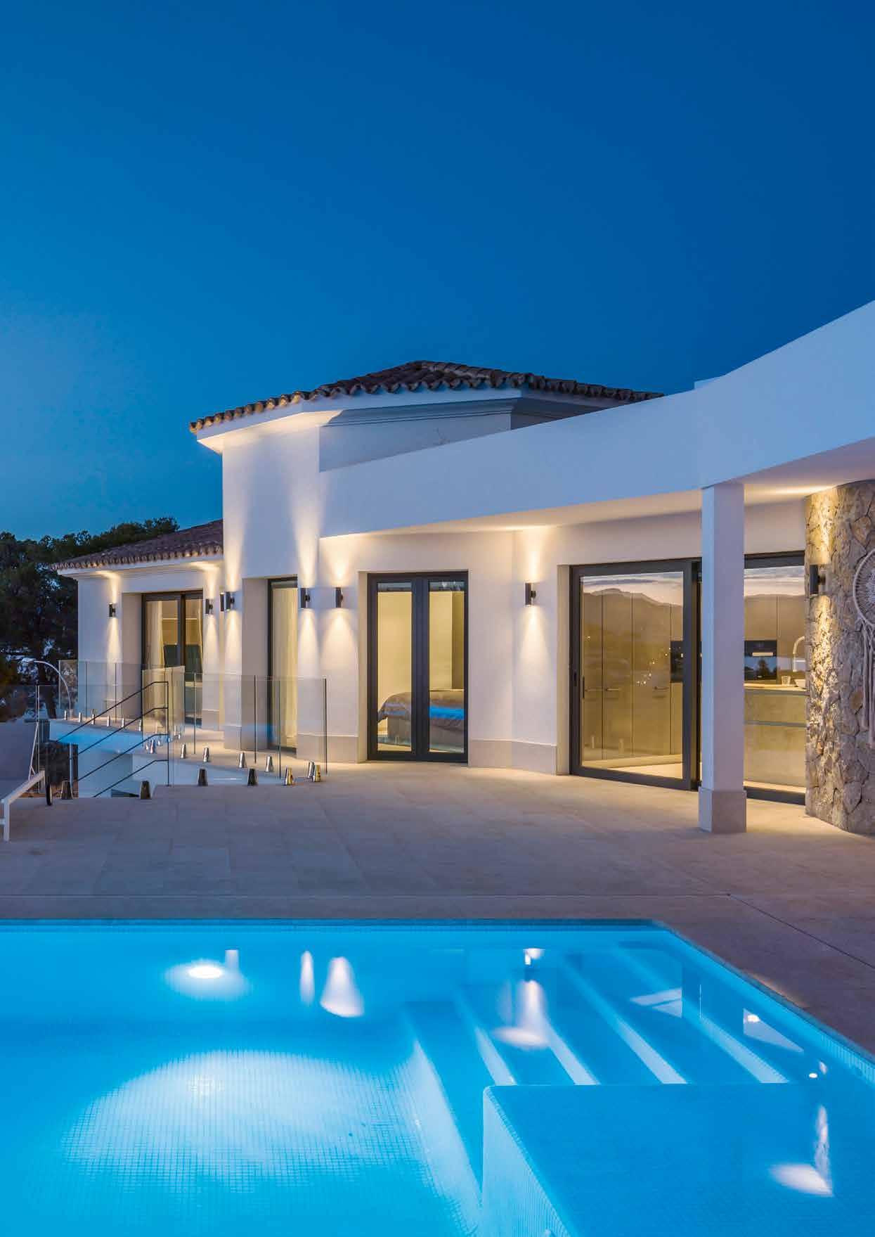
© GERMÁN CABO
INTRODUCTION 5 4 INTRODUCTION
KNX – the worldwide standard with system
KNX has been a worldwide standard for over 30 years and represents a strong international community. The European standard EN 50090 has become established as a global standard in accordance with ISO/IEC 14543-3. The “KNX” label makes clear the system compatibility of the products of all manufacturers.

FUTURE-PROOF
KNX as building system technology is consistently further developed. As international standard, KNX is future-oriented and guarantees constant upgradeability when new components appear, also manufacturer-independent.
INVESTMENT SECURITY
High quality, certified KNX products and the global standardisation guarantee a sustainable investment in a long-lasting system. The KNX system has existed for more than 30 years and first generation devices are still compatible with the latest KNX products.
INTEROPERABILITY
Products with the KNX logo speak and understand the KNX language. They are programmed and put into operation using the manufacturer-independent Engineering Tool (ETS™). Strict KNX interworking rules ensure that the certified products of different manufacturers can communicate with each other in the various applications. KNX has standardised complete sets of data types for a large number of functions for this.
DECENTRALISED SYSTEM DESIGN
KNX functions as a modular system. Network and building technology can thus be expanded and rebuilt in any way at any time. Customised and economic solutions can always be found for small or large projects, modernisation or new construction.
DATE: OCTOBER 2020 30 years of experience KNX – FACTS AND FIGURES 1990 93,000 partners in 190 countries 515 training centres 500 manufacturers INTRODUCTION 7 6 INTRODUCTION
Life in the smart home: functions and applications
KNX is the future-proof solution for the professional smart home: the lighting scene in the living room matches the well-being temperature perfectly. It stays pleasantly cool in the bedroom because the shutters automatically descend when the sun shines in. Your favourite music can be heard in every room thanks to multi-rooming. With intelligent technology from JUNG.
LIGHTING
Individual control of the indoor and outdoor lighting. Automatically, as needed and thus energy saving.

MONITORING/ALARM SIGNALLING
Sensors for monitoring windows and doors, central on/off controls and notification and alarm systems give a secure feeling.
MULTIMEDIA
Multi-rooming in the entire house, TV and entertainment systems and multimedia components are integrated in KNX.
BLINDS AND SHUTTERS
The automatic control of blinds and shutters including louvre adjustment is regulated by sunlight. The control is performed centrally or decentralised.
HEATING, VENTILATION, AIR CONDITIONING
Demand-based control of heating, ventilation and air conditioning ensure not only the individual feel-good temperature but also a healthy room climate.
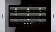
VISUALISATION AND REMOTE CONTROL
Show and operate all states in your own home using touch displays. Also when on the move from smart phones and tablets.
INTRODUCTION 9 8 INTRODUCTION
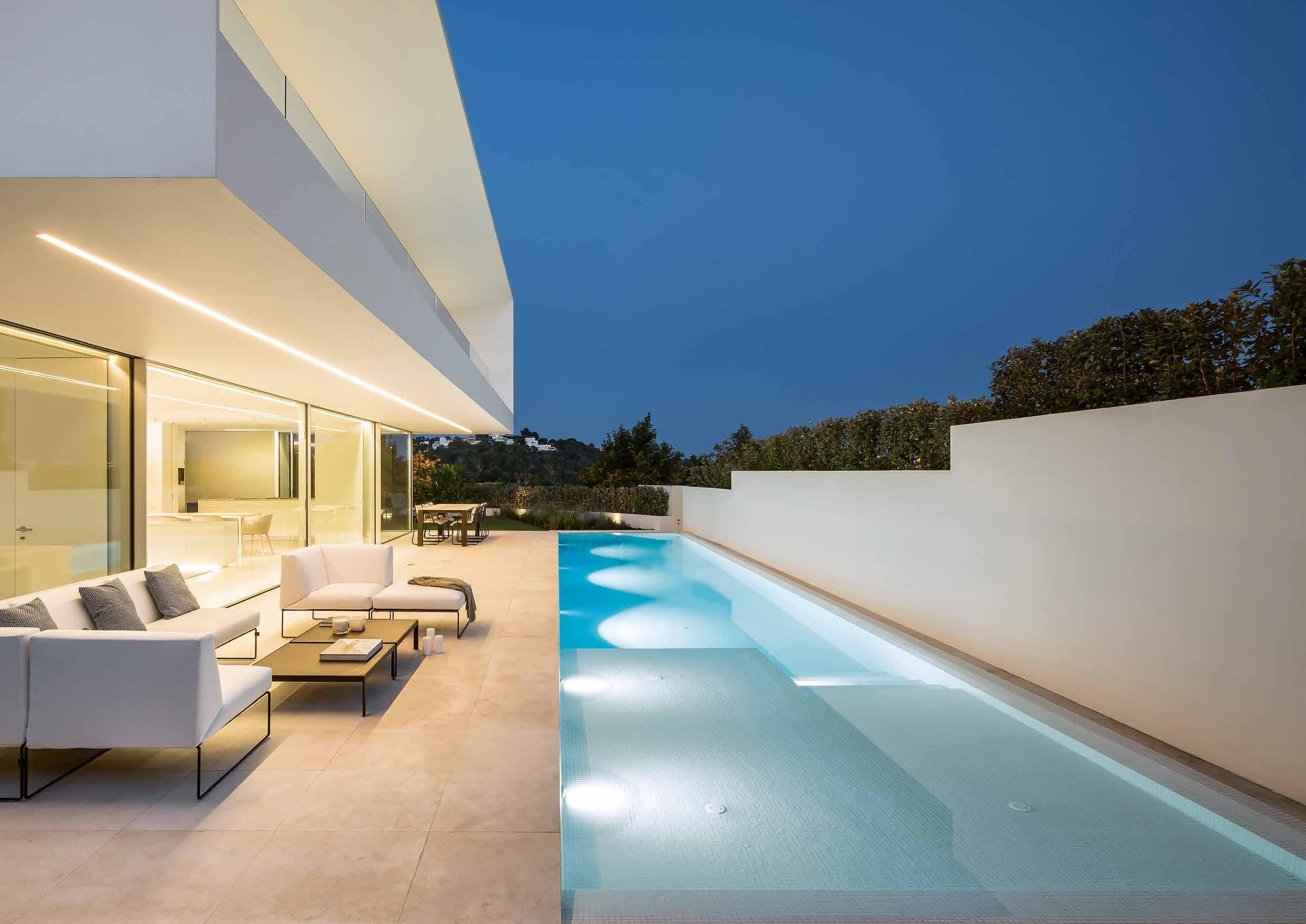
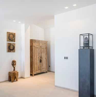
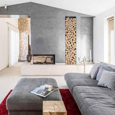
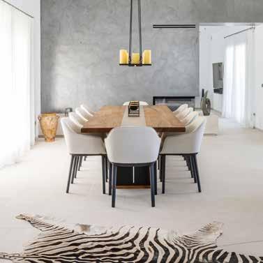
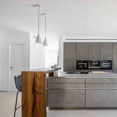
Cultivated objectivity
Smart building technology in prestigious architecture – combined with one high aspiration: only the best, always. Owners in the whole world have confidence in intelligent KNX technology for their homes. Implemented in the varied JUNG design, the smart technology integrates seamlessly into virtually every interior.

INTRODUCTION 11 10 INTRODUCTION
Finca, Mallorca Architect/Planner: APM Mallorca, Santa Ponsa Equipped with JUNG KNX technology in the LS 990 range
Smart and economical
Investment security is the main argument for the decision for building automation in office and administrative building construction. It should also be cost-effective, energy-efficient and functional. Additionally important: Flexibility in adaptation to changing renting situations. The good thing here is that owners and planners worldwide can rely here on the smart KNX solutions of JUNG.


© KURT KUBALL ARCHITEKTURFOTOGRAFIE INTRODUCTION 13 12 INTRODUCTION
Vienna Biocenter, Vienna Architect: ATP architekten ingenieure Equipped with JUNG KNX technology in the LS 990 range.
Intelligent comfort
Hotel operators worldwide have confidence in the advantages of intelligent KNX technology from JUNG. Whether well-known hotel chains such as the Hilton Group with its Hilton Hotel Astana in Kazakhstan or first-class family and designer hotels: with KNX, maximum comfort for the guest is combined with reliability and cost effectiveness for the operating company in a uniquely smart way.


 Hilton Hotel Astana, Kazakhstan
Architect/Planner: INK Architects, Almaty, Nurly Tau BC Equipped with JUNG KNX technology in the LS 990 range
Hilton Hotel Astana, Kazakhstan
Architect/Planner: INK Architects, Almaty, Nurly Tau BC Equipped with JUNG KNX technology in the LS 990 range
© 2019 HILTON INTRODUCTION 15 14 INTRODUCTION
Systematically networked: the JUNG KNX system
26
MANUAL SENSORS
The execution of the commands and implementation of the physical states for the manual sensors are performed manually by pressing buttons or rotary movements for rotary dimmers. The information is forwarded via the KNX bus to the implementing devices.
120
AUTOMATIC SENSORS
Presence detectors, weather stations and room temperature controllers, among other things, convert physically measured factors into electrical values, process these and send a telegram on the KNX bus for implementation of the relevant commands.
152
SYSTEM DEVICES
The different KNX system devices are needed for the establishment of the bus structure (line and area couplers), as interfaces for the programming and operation of the KNX installation.
168
ACTUATORS
Actuators receive information from the sensors, execute commands and feed back current states to the display elements of the sensors. Appropriate actuators in different designs are available in the JUNG KNX system for every application.
170
GATEWAYS
The KNX gateways form an interface between KNX and an external network, such as IP. Thereby, they translate the incoming and outgoing messages and transfer the data of the two different networks.
248
CENTRAL CONTROL
The various KNX central control units form the node for networking and common control of all KNX functions, both room-related as well as for the entire building.
KNX line Weather station Signal panel Rotar y sensor F 50 F 40 F 10 Room thermostat External system Room controller CO sensor CO 2 Presence detector Automatic switch with alarm indicator Wind sensor Control with touch display Power supply Media coupler Line coupler IP inter face Sonos Gateway Blinds actuator Dimming actuator Switch actuator Heating actuator DALI Gateway Smar t Visu Ser ver Visu Pro Ser ver / Visu Pro Sof tware itamotuA c srosnes Central c ontrol M a n u a l s e n s o r s A c t u a tors Systemdevi c e s Gateways
JUNG KNX SYSTEM 17 16 JUNG KNX SYSTEM
JUNG KNX Secure: security in the field bus and IP network
The discussion about data protection also does not stop at a smart building. Because everything you can operate digitally yourself, can theoretically also be controlled by unauthorised third parties. This is where JUNG KNX Secure comes in and provides effective protection thanks to encryption with the AES128 algorithm.
KNX Secure provides double protection: KNX


IP Secure encrypts the transmission at network layer. It authenticates selected telegrams regardless of the medium and encrypts the transmitted data with the AES128 algorithm. Thus the communication between sensor and actuator in the IP network cannot be interpreted or manipulated. This also ensures
secure communication with visualisations.
KNX Data Secure also encrypts and authenticates the data on the bus line (TP)1 or via wireless communication (RF) 2. This reliably prevents attack scenarios such as telegram recording, telegram repetitions (replay attack) or modification (man-in-the-middle attack).
2 4 6 3 5
7 8 1 2 4 6 3 5 1
DUE TO INTELLIGENT JUNG TOPOLOGY 1 KNX system device 2 KNX RF 2 media coupler 3 KNX power supply insert 4 KNX RF2 node 5 KNX TP1 actuator 6 KNX TP1 sensor 7 JUNG Visu Pro 8 LAN router KNX bus line Data Secure IP Secure3 KNX Secure 1 TP: Twisted pair RF: Radio frequency 3 IP Secure: https encrypted TOPOLOGY 19 18 TOPOLOGY
Room2
Room1
PROTECTED
JUNG KNX Secure: Secure & fast in operation
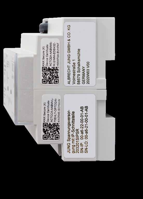
Professional installers need the certificates of the individual KNX Secure components to make a KNX installation secure. They are printed on the devices as a QR code and must be integrated into the ETS. The easiest way to do this is via app.
1. INSTALL JUNG KNX SECURE SCANNER APP
The smartphone app is installed before the installation. KNX Secure Scanner is available in the app stores of Apple and Google at no charge. Using the KNX Secure Scanner app, installers can easily scan the QR codes on JUNG KNX devices.
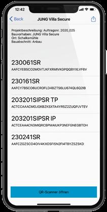

2. REGISTER CERTIFICATES VIA SMARTPHONE APP
The scanning with the JUNG KNX Secure Scanner app is quick and easy. The keys are shown there as a list view. With the app, the installer then creates a protected JSON file or lists the Secure keys in a password-protected PDF. Then the KNX components are installed.
3. IMPORTING CERTIFICATES WITH THE KNX SECURE KEY LOADER
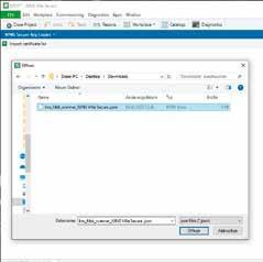
In order to securely integrate the scanned device certificates into the ETS, the installer transfers the JSON files created with the JUNG KNX Secure Scanner to their computer. Several files can come together there, which the installer archives and imports into the ETS project using the ETS app JUNG KNX Secure Key Loader.
JUNG KNX Secure
On the following pages you will find numerous products that support KNX Secure. They are appropriately identified with this symbol.

20 KNX SECURE KNX SECURE 21
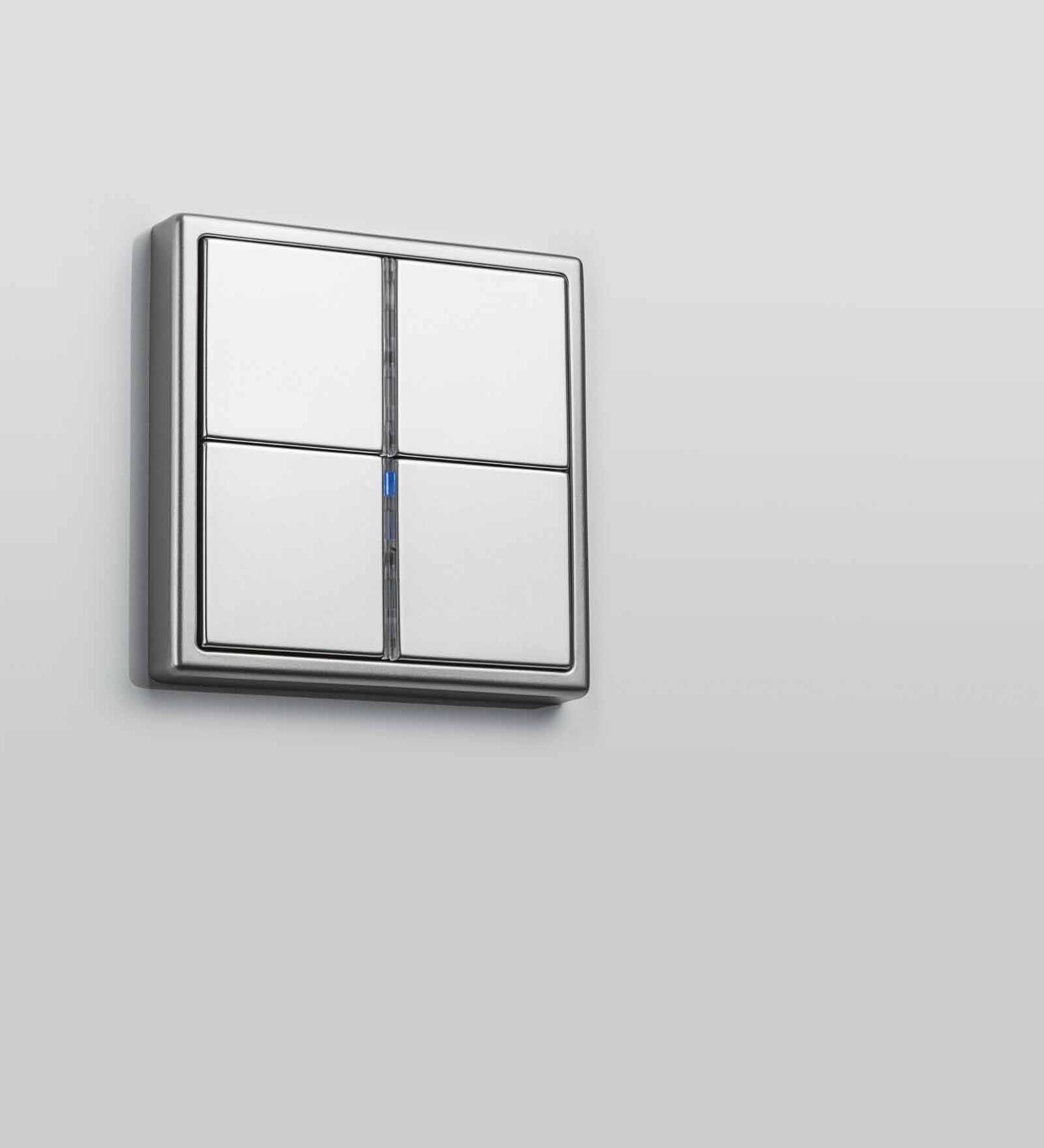
Operating KNX in the JUNG design


When the design makes the operation self-explanatory: the JUNG F 50 push-button sensors impress with high-quality materials. The clear shape stylishly complements the operating concept.
 Compact Room Controller F 50
LS 990 in black/stainless steel
PUSH-BUTTON SENSOR F 50 PUSH-BUTTON SENSOR F 40
KNX PUSH-BUTTON SENSOR F 10 ROTARY SENSOR
in AS 500 in white
in A FLOW in matt anthracite
in CD 500 in light grey
in LS 990 in aluminium
Compact Room Controller F 50
LS 990 in black/stainless steel
PUSH-BUTTON SENSOR F 50 PUSH-BUTTON SENSOR F 40
KNX PUSH-BUTTON SENSOR F 10 ROTARY SENSOR
in AS 500 in white
in A FLOW in matt anthracite
in CD 500 in light grey
in LS 990 in aluminium
PUSH-BUTTON SENSORS/ROOM CONTROLLERS 23 22 PUSH-BUTTON SENSORS/ROOM CONTROLLERS
Clear labelling
JUNG components are labelled according to individual requirements using the Graphic Tool. Using laser engraving or colour printing process depending on material and colour. Whether produced for the entire building or for one piece. Inscription fields can also be printed independently above the labelling.
LASER ENGRAVING
Precise erosion of the surface for a particularly valued appearance: the finest contours of symbols and texts must also be realised using laser engraving. A striking form of product refinement, particularly for the metal variants.
Labelling in the catalogue part:
COLOUR PRINTING

Easily integrate the design of the electrical installation in your own corporate design – using abrasion-resistant colour printing. Symbols, individual texts and patterns also give the elements an unmistakeable look.
Labelling in the catalogue part:
LABELLING
Many Jung products have an integrated labelling field. These can be printed with text or symbols using the labelling. The functions of KNX sensors and more are clearly identified.

Graphic-Tool online: jung.de/gt
F 40
LS
L P PUSH-BUTTON SENSORS/ROOM CONTROLLERS 25 24 PUSH-BUTTON SENSORS/ROOM CONTROLLERS
push-button sensor
990 in stainless steel
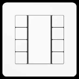
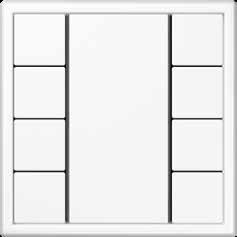
The F 50 family
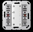
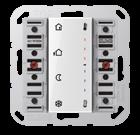
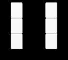
The KNX F 50 push-button sensors provide plenty of space on the concise information area for individual marking with the Graphic Tool. Operation is then via the buttons arranged at the side.
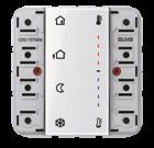
PUSH-BUTTON SENSORS
For the control of functions and scenes. The scope of delivery includes the transparent design of the cover with a large labelling area as standard; this can optionally be replaced with a coloured version.
PUSH-BUTTON SENSORS RF
KNX RF is the manufacturer-independent KNX wireless standard. These push-button sensors have the same operating concept and design as the well-known push-button sensors with twisted pair connection.
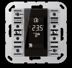
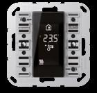
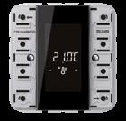
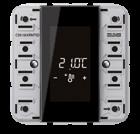
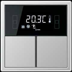
COMPACT ROOM CONTROLLER
Impressive thanks to an intuitive operating concept and two integrated temperature controllers. The backlit LC display clearly legibly shows the most important values and functions.
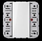
ROOM TEMPERATURE CONTROLLER
Device for individual room temperature control. The default can be changed to the push-button sensor functions of switching, dimming, blinds, transducers, or scenes.
PUSH-BUTTON SENSORS/ROOM CONTROLLERS 27 26 PUSH-BUTTON SENSORS/ROOM CONTROLLERS
Push-button sensor F 50 LS 990 in aluminium/chrome
Individual button assignment
TWO-BUTTON OPERATION TWO-BUTTON OPERATION
Two functions (operation left/right)
Two functions (operation up/down)
ONE-BUTTON OPERATION 90° MOUNTING
Four functions (toggle)
Possible in one or two-button operation

Two operating modes can be set in principle on the F 50 push-button sensor Standard and Universal: one-button operation and two-button operation. In the case of the two-button version, the operation can be optionally programmed for up/ down or left/right. Horizontal mounting with appropriate button assignment can also be implemented.

Push-button sensor F 50 LS 990 in aluminium
1 3 2 4 1 2 3 4 PUSH-BUTTON SENSORS/ROOM CONTROLLERS 29 28 PUSH-BUTTON SENSORS/ROOM CONTROLLERS
Illuminating: the RGB LEDs
F 50 push-button sensors Universal have an operation LED and a status LED per button. These can be freely set in red, green and blue. The LEDs and the illuminated labelling area can each be adjusted for brightness so that, for example, one LED can be used as a pilot light.
Versatile functionality
THE DESIGN COVER
The design cover is available as a transparent version and as coloured variant – that is unique in the market.
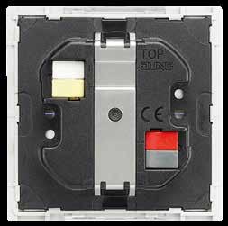
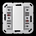
OPTIMISED: THE INSTALLATION
Flat design and low installation depth make the push-button sensors easy to mount. The easily accessible terminals for the KNX bus and the push-button extension module are clearly labelled:

1 Extension module
2 KNX bus
PRACTICAL: THE CONSTRUCTION SITE COVERAGE
Thanks to the construction site coverage, button and function assignment can already be realised in construction site operation. The decision for button and cover design thus has time until the project acceptance.
INTEGRATED: THE TEMPERATURE SENSOR*
The temperature at various places in the room can be measured with the temperature sensor. The values are transmitted to the room temperature controller or room controller for effective control.
ENLIGHTENING: THE LIGHT SCENE MEMORY*
Up to 8 light scenes can be stored in the integrated light scene memory; in turn, eight groups can be assigned to each scene. These scenes can be called up using buttons or other KNX commands. *
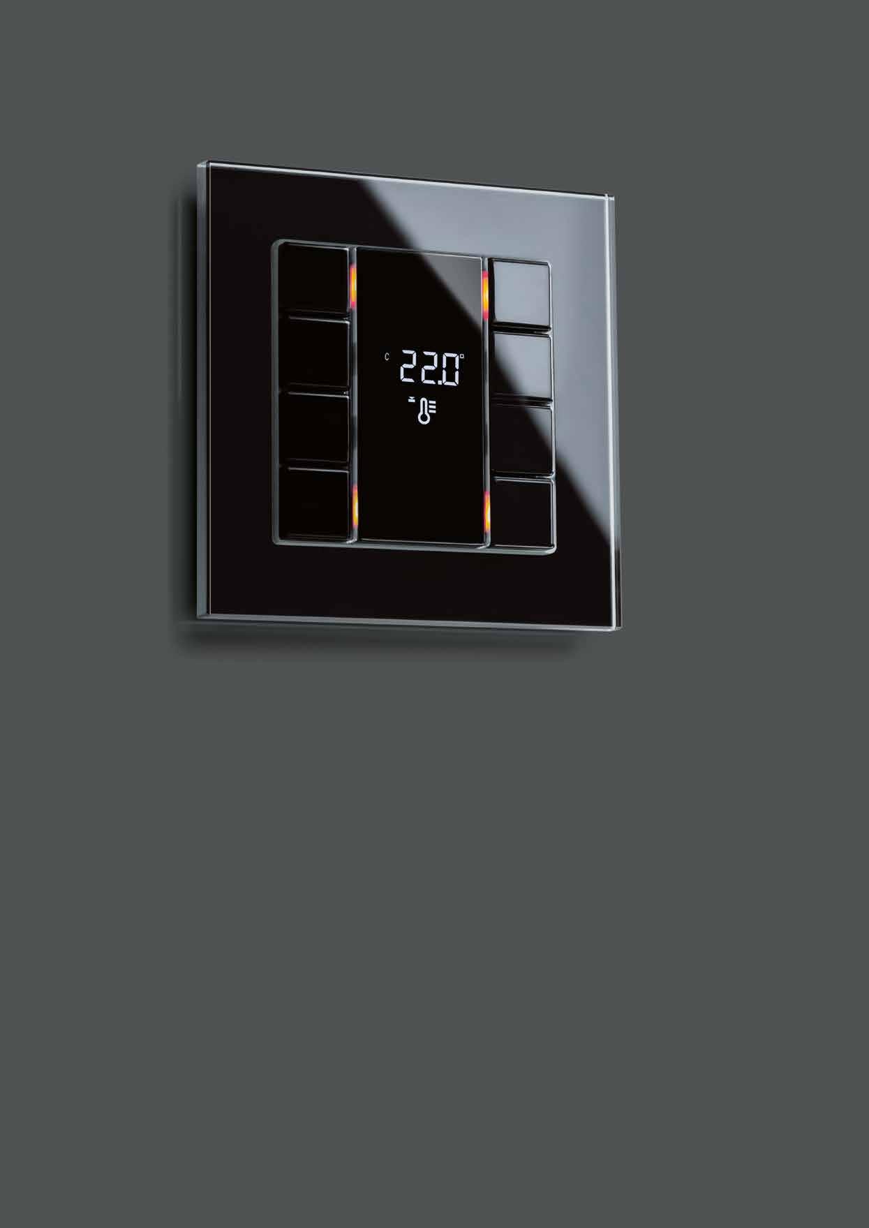
Compact Room Controller F 50 A CREATION in black with glass frame
Universal version
only for
1 2 LIGHT BLINDS OFF/ON PUSH-BUTTON SENSORS/ROOM CONTROLLERS 31 30 PUSH-BUTTON SENSORS/ROOM CONTROLLERS
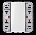
Efficient and flexible: Push-button extension module F 50
The push-button extension module complements an F 50 installation with additional, cost-effective satellites.
- 40%
COST SAVING
In comparison with exclusive use of push-button sensors in the KNX installation shown, the saving is 40%.
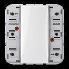
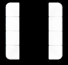
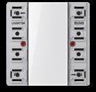
PUSH-BUTTON EXTENSION MODULE
The functions can be extended by connecting the 1 to 4-gang push-button extension module, while at the same minimising the load on the bus. Particularly the option for installation of the extension module at a distance of up to 30 m provides more flexibility.
Compact room controller ROOM 1 ROOM 2 ROOM 3 Compact room controller Extension module Extension module max. 30m max. 30m KNX line Basic module Extension module KNX line
PUSH-BUTTON SENSORS/ROOM CONTROLLERS 33 32 PUSH-BUTTON SENSORS/ROOM CONTROLLERS
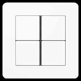
Variety of designs


High quality materials and distinctive forms determine the JUNG design. The AS, A, CD and LS ranges give the KNX sensors their attractive appearance. They can be selected to match the ambiance for each room.


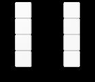
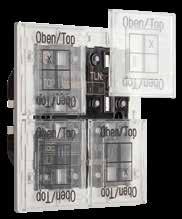
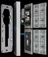
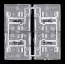
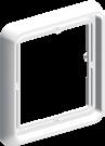
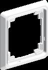
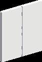
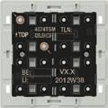
Modular system
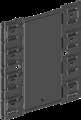

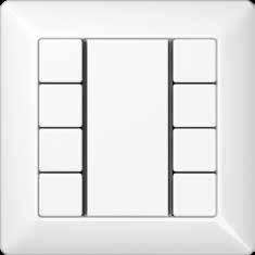
The 1, 2, 3 and 4-gang F 50 modules are available in the JUNG design alongside the corresponding 1 to 4-gang cover kits. The transparent or coloured labelling field is optionally added to this. The design frames of the various ranges round off the concept.


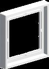
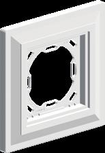
USING THE LS RANGE AS AN EXAMPLE 1 Supporting ring 2 Plastering adapter 3 Frame 4 Push-button module 5 Cover kit 6 Labelling field 1 3 2 4 5 1-gang 2-gang 3-gang transparent coloured 4-gang 6 LS 990 LS DESIGN LS PLUS LS ZERO in white in white in white in white LS 990 A FLOW CD 500 AS 500 PUSH-BUTTON SENSORS/ROOM CONTROLLERS 35 34 PUSH-BUTTON SENSORS/ROOM CONTROLLERS
KNX AS range and A range
F 50
Ref.-no.
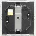
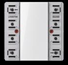
KNX standard push-button module including transparent cover ref.-no.: A 50 NA
Intended use
• Operation of loads, e.g. light on/off, dimming, blinds up/down, calling up and saving light scenes, etc.
• Installation in flush box according to DIN 49073
Product characteristics
• KNX medium: TP 256

• Push-button functions switching, dimming, blind control, value transmitter, scene recall, etc.
• To be completed with cover kit
• Inscription field
• One red status LED for a pair of buttons
• One operation LED as orientation light and programming status – red, green or blue, adjustable
• Energy saving mode
• Integrated bus coupling unit
• Transparent cover kit (included) for temporary site use without design covers
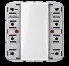
KNX standard push-button module, 1-gang for cover kit 1-gang, ref.-no.: A 501 TSA ..
ETS product family: Push-button
Product type: 1-gang push-button
KNX standard push-button module, 2-gang for cover kit 2-gang, ref.-no.: A 502 TSA ..
ETS product family: Push-button
Product type: 2-gang push-button
A 5071 TSM
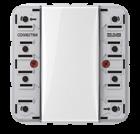
KNX standard push-button module, 3-gang for cover kit 3-gang, ref.-no.: A 503 TSA ..
ETS product family: Push-button
Product type: 3-gang push-button
A 5072 TSM
KNX standard push-button module, 4-gang for cover kit 4-gang, ref.-no.: A 504 TSA ..
ETS product family: Push-button
Product type: 4-gang push-button
A 5073 TSM
A 5074 TSM
36
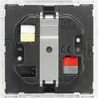
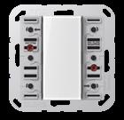
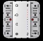
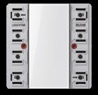
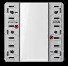
KNX universal push-button module including transparent cover ref.-no.: A 50 NA
Intended use
• Operation of loads, e.g. light on/off, dimming, blinds up/down, brightness values, temperatures, calling up and saving light scenes, etc.
• Installation in flush box according to DIN 49073
Product characteristics
• KNX medium: TP 256
• Push-button functions switching, dimming, blind control, value transmitter, scene recall, etc.
• One or two functions per button
• To be completed with cover kit
• Inscription field can be illuminated
• One status LED per button, red, green or blue, adjustable
• One operation LED as orientation light and programming status – red, green or blue, adjustable
• Brightness of status LED, operation LED and inscription field adjustable, can be changed during operation, e.g. during night times
• Measurement of room temperature
• Extension unit for room temperature controller
• Disabling function: Disabling or change function mode of single or all button functions
• Alarm function, optional acknowledge by pressing any button
• Energy saving mode
• Integrated bus coupling unit
• Connection for a push-button extension module, 1-4 gang
• Transparent cover kit (included) for temporary site use without design covers
KNX universal push-button module, 1-gang for cover kit 1-gang, ref.-no.: A 501 TSA .. can be extended by means of a push-button extension module, ref.-no.: A 509.. TSEM
ETS product family: Push-button
Product type: 1-gang push-button
A 5091 TSM
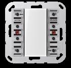
KNX universal push-button module, 2-gang for cover kit 2-gang, ref.-no.: A 502 TSA .. can be extended by means of a push-button extension module, ref.-no.: A 509.. TSEM
ETS product family: Push-button
Product type: 2-gang push-button
A 5092 TSM
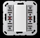
KNX universal push-button module, 3-gang for cover kit 3-gang, ref.-no.: A 503 TSA .. can be extended by means of a push-button extension module, ref.-no.: A 509.. TSEM
ETS product family: Push-button
Product type: 3-gang push-button
A 5093 TSM
KNX universal push-button module, 4-gang for cover kit 4-gang, ref.-no.: A 504 TSA .. can be extended by means of a push-button extension module, ref.-no.: A 509.. TSEM
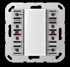
ETS product family: Push-button
Product type: 4-gang push-button
A 5094 TSM
Ref.-no. 37 KNX
F 50
AS range and A range
KNX AS range and A range
F 50
Ref.-no.
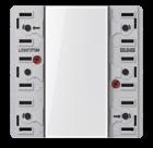
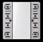
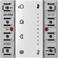
KNX room temperature controller module 2-gang including transparent cover and inlay with symbols for cover kit 2-gang, ref.-no.: A 502 TSA ..
Intended use
• Single-room temperature control in KNX installations
A 5178 TSM
• Operation of loads, e.g. light on/off, dimming, blinds up/down, calling up and saving light scenes, etc.
• Installation in flush box according to DIN 49073
Product characteristics
All buttons can be assigned with push-button sensor functions or functions for controller operation.
• KNX medium: TP 256
• Measurement of room temperature
• Room temperature control with setpoint value specification
• Extension unit for room temperature controller
• Push-button functions switching, dimming, blind control, value transmitter, scene recall, etc.
• One or two functions per button
• Completion with cover kit 2-gang
• Inscription field can be illuminated
• Two red status LEDs per button – red, green or blue adjustable
• One operation LED as an orientation light and to indicate the programming status – red, green or blue adjustable
• Brightness of status LEDs, operation LED and labelling field adjustable; switchable while in operation, e.g. during the night
• Disabling function: Disabling or change function mode of single or all button functions
• Alarm function, optional acknowledge by pressing any button
• Energy saving mode (for operation without controller function)
• Integrated bus coupling unit
• Connection for a push-button extension module, for extension with up to eight additional buttons
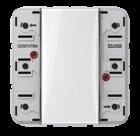
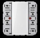
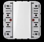
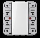
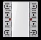
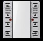
Push-button extension module including transparent cover ref.-no.: A 50 NA for the extension of the Universal push-button module (ref.-no.: A 509.. TSM) and room temperature controller module (ref.-no.: A 5178 TSM) with up to 4 additional push-buttons
Product characteristics
• One or two functions per button
• To be completed with cover kit
• Inscription field can be illuminated
• One status LED per button, red, green or blue, adjustable
• One operation LED as orientation light and programming status – red, green or blue, adjustable
• Brightness of status LED, operation LED and inscription field adjustable, can be changed during operation, e.g. during night times
• Measurement of room temperature
• Extension unit for room temperature controller
• Disabling function: Disabling or change function mode of single or all button functions
• Alarm function, optional acknowledge by pressing any button
• Energy saving mode
• Transparent cover kit (included) for temporary site use without design covers
Technical data
Cable length: max. 30 m
Cable type: J-Y(St)Y 2 x 2 x 0.8 mm
38
A 5091 TSEM 2-gang A 5092 TSEM 3-gang A 5093 TSEM 4-gang A 5094 TSEM
1-gang
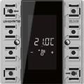
KNX room controller display compact module 2-gang for cover kit 2-gang, ref.-no.: A 502 TSA .. can be extended by means of a room controller extension module, ref.-no.: A 5178 TSEM can be extended by means of a push-button extension module, ref.-no.: A 509.. TSEM
A 5192 KRM TS D
Technical data
Recommended mounting height: 1.5 m
KNX room controller display compact module 4-gang for cover kit 4-gang, ref.-no.: A 504 TSA .. can be extended by means of a room controller extension module, ref.-no.: A 5178 TSEM can be extended by means of a push-button extension module, ref.-no.: A 509.. TSEM
Intended use
• Measurement and feedback control of the room temperature
• Operation of loads, e.g. light on/off, dimming, blinds up/down, brightness values, temperatures, calling up and saving light scenes, etc.
• Installation in flush box according to DIN 49073
Product characteristics
All buttons can be assigned with push-button sensor functions or functions for controller operation.
• KNX medium: TP 256
• Backlit LC display
• One or two functions per button
• To be completed with cover kit
• Eight status LEDs – red, green or blue
• Brightness of status LEDs and LCD adjustable
• Integrated bus coupling unit
• Connection of extension modules
• Integrated room temperature sensor
• External sensor (ref.-no.: FF 7.8) can be connected
• Room temperature control with setpoint value specification
• Two internal independent controllers for two independent areas – in connection with extension modules
• Display of room or set temperature (°C or °F)
• Display of outdoor temperature – with external sensor, e.g. weather station
• Display of time, in conjunction with KNX time encoder (in menu level)
• Push-button function or rocker function
• Disabling function: Disabling or change function mode of single or all button functions
• Alarm function, optional acknowledge by pressing any button
Technical data
Recommended mounting height: 1.5 m
Room controller extension module 2-gang for cover kit 2-gang, ref.-no.: A 502 TSA .. for the extension of a room controller module (ref.-no.: A 5192 KRM TS D, A 5194 KRM TS D) with a second room temperature control unit
Intended use
• Operation of loads, e.g. light on/off, dimming, blinds up/down, brightness values, temperatures, calling up and saving light scenes, etc.
• Measurement of room temperature
• Extension for room controller modules (.. 5192 KRM TS D, .. 5194 KRM TS D)
• Installation in flush box according to DIN 49073
Technical data
Cable length: max. 30 m
Cable type: J-Y(St)Y 2 x 2 x 0.8 mm
39 KNX AS
and
F 50
Ref.-no.
range
A range
A 5194 KRM TS D
A 5178 TSEM
KNX AS range and A range

F 50
Delivery of cover kits: 1 complete set per ref.-no.!
Cover kit 1-gang
to clip on F 50 push-button modules 1-gang of the AS/A range
ref.-no.: A 5071 TSM, A 5091 TSM, A 5091 TSEM, A 5071 RF TSM, A 5212 TSM, FM A 5001 M
Thermoplastic (breakproof) high-gloss
Cover kit 2-gang
to clip on F 50 push-button modules 2-gang of the AS/A range
ref.-no.: A 5072 TSM, A 5092 TSM, A 5092 TSEM, A 5178 TSM, A 5192 KRM TS D, A 5178 TSEM, A 5072 RF TSM, A 5224 TSM, FM A 5002 M
Thermoplastic (breakproof) high-gloss
Thermoplastic (breakproof) lacquered
Cover kit 3-gang
to clip on F 50 push-button modules 3-gang of the AS/A range
ref.-no.: A 5073 TSM, A 5093 TSM, A 5093 TSEM, A 5073 RF TSM, A 5236 TSM, FM A 5003 M, SI TM A 5073, SI TM A 5093
Thermoplastic (breakproof) high-gloss
Thermoplastic (breakproof) lacquered
40
Ref.-no.
ivory L A 501 TSA white L A 501 TSA WW black L A 501 TSA SW
aluminium P L A 501 TSA AL champagne P A 501 TSA CH mocha A 501 TSA MO matt lacquered matt snow white N A 501 TSA WWM matt graphite black N A 501 TSA SWM matt anthracite A 501 TSA ANM
Thermoplastic (breakproof) lacquered
ivory L A 502 TSA white L A 502 TSA WW black L A 502 TSA SW
aluminium P L A 502 TSA AL champagne P A 502 TSA CH mocha A 502 TSA MO matt lacquered matt snow white N A 502 TSA WWM matt graphite black N A 502 TSA SWM matt anthracite A 502 TSA ANM
ivory L A 503 TSA white L A 503 TSA WW black L A 503 TSA SW
aluminium P L A 503 TSA AL champagne P A 503 TSA CH mocha A 503 TSA MO matt lacquered matt snow white N A 503 TSA WWM matt graphite black N A 503 TSA SWM matt anthracite A 503 TSA ANM
Delivery of cover kits: 1 complete set per ref.-no.!
Cover kit 4-gang
to clip on F 50 push-button modules 4-gang of the AS/A range ref.-no.: A 5074 TSM, A 5094 TSM, A 5094 TSEM, A 5194 KRM TS D, A 5074 RF TSM, A 5248 TSM, FM A 5004 M
Thermoplastic (breakproof) high-gloss
ivory
white

black
Thermoplastic (breakproof) lacquered
aluminium
champagne
mocha
matt lacquered
matt snow white
matt graphite black
matt anthracite
Transparent cover with paper inlay (Spare part)
range and A range
Ref.-no.
L A 504 TSA
L A 504 TSA WW
L A 504 TSA SW
P L A 504 TSA AL
P A 504 TSA CH
A 504 TSA MO
N A 504 TSA WWM
N A 504 TSA SWM
A 504 TSA ANM
to clip on F 50 push-button modules of the AS/A range ref.-no.: A 507.. TSM, A 509.. TSM, A 509.. TSEM, A 5178 TSM, A 51.. KRM TS D, A 5178 TSEM, A 507.. RF TSM, A 52.. TSM, FM A 50.. M
Also included in delivery of modules.
inscription field 25 x 52.5 mm paper inlay pearly
A 50 NA
Neutral cover to clip on F 50 push-button modules of the AS/A range ref.-no.: A 507.. TSM, A 509.. TSM, A 509.. TSEM, A 5178 TSM, A 51.. KRM TS D, A 5178 TSEM, A 507.. RF TSM, A 52.. TSM, FM A 50.. M
dimensions: 25 x 55 mm

Thermoplastic (breakproof) high-gloss
Thermoplastic (breakproof) lacquered
Professional inscription see www.jung.de/gt
41 KNX
F 50
AS
ivory L A 50 NA W white L A 50 NA WW black L A 50 NA SW
aluminium P L A 50 NA AL champagne P A 50 NA CH mocha A 50 NA MO matt lacquered matt snow white N A 50 NA WWM matt graphite black N A 50 NA SWM matt anthracite A 50 NA ANM
KNX CD range F 50
Ref.-no.
KNX standard push-button module including transparent cover ref.-no.: CD 50 NA
Intended use
• Operation of loads, e.g. light on/off, dimming, blinds up/down, calling up and saving light scenes, etc.
• Installation in flush box according to DIN 49073
Product characteristics
• KNX medium: TP 256
• Push-button functions switching, dimming, blind control, value transmitter, scene recall, etc.
• To be completed with cover kit
• Inscription field
• One red status LED for a pair of buttons
• One operation LED as orientation light and programming status – red, green or blue, adjustable
• Energy saving mode
• Integrated bus coupling unit
• Transparent cover kit (included) for temporary site use without design covers
KNX standard push-button module, 1-gang for cover kit 1-gang, ref.-no.: CD 501 TSA ..
ETS product family: Push-button
Product type: 1-gang push-button
KNX standard push-button module, 2-gang for cover kit 2-gang, ref.-no.: CD 502 TSA ..
ETS product family: Push-button
Product type: 2-gang push-button
CD 5071 TSM
KNX standard push-button module, 3-gang for cover kit 3-gang, ref.-no.: CD 503 TSA ..
ETS product family: Push-button
Product type: 3-gang push-button
CD 5072 TSM
KNX standard push-button module, 4-gang for cover kit 4-gang, ref.-no.: CD 504 TSA ..
ETS product family: Push-button
Product type: 4-gang push-button
CD 5073 TSM
CD 5074 TSM
42
KNX universal push-button module including transparent cover ref.-no.: CD 50 NA
Intended use
• Operation of loads, e.g. light on/off, dimming, blinds up/down, brightness values, temperatures, calling up and saving light scenes, etc.
• Installation in flush box according to DIN 49073
Product characteristics
• KNX medium: TP 256
• Push-button functions switching, dimming, blind control, value transmitter, scene recall, etc.
• One or two functions per button
• To be completed with cover kit
• Inscription field can be illuminated
• One status LED per button, red, green or blue, adjustable
• One operation LED as orientation light and programming status – red, green or blue, adjustable
• Brightness of status LED, operation LED and inscription field adjustable, can be changed during operation, e.g. during night times
• Measurement of room temperature
• Extension unit for room temperature controller
• Disabling function: Disabling or change function mode of single or all button functions
• Alarm function, optional acknowledge by pressing any button
• Energy saving mode
• Integrated bus coupling unit
• Connection for a push-button extension module, 1-4 gang
• Transparent cover kit (included) for temporary site use without design covers
KNX universal push-button module, 1-gang for cover kit 1-gang, ref.-no.: CD 501 TSA .. can be extended by means of a push-button extension module, ref.-no.: CD 509.. TSEM
ETS product family: Push-button
Product type: 1-gang push-button
CD 5091 TSM
KNX universal push-button module, 2-gang for cover kit 2-gang, ref.-no.: CD 502 TSA .. can be extended by means of a push-button extension module, ref.-no.: CD 509.. TSEM
ETS product family: Push-button
Product type: 2-gang push-button
CD 5092 TSM
KNX universal push-button module, 3-gang for cover kit 3-gang, ref.-no.: CD 503 TSA .. can be extended by means of a push-button extension module, ref.-no.: CD 509.. TSEM
ETS product family: Push-button
Product type: 3-gang push-button
CD 5093 TSM
KNX universal push-button module, 4-gang for cover kit 4-gang, ref.-no.: CD 504 TSA .. can be extended by means of a push-button extension module, ref.-no.: CD 509.. TSEM
ETS product family: Push-button
Product type: 4-gang push-button
CD 5094 TSM
Ref.-no. 43 KNX CD range F 50
KNX CD range F 50
Ref.-no.
KNX room temperature controller module 2-gang including transparent cover and inlay with symbols for cover kit 2-gang, ref.-no.: CD 502 TSA ..
Intended use
• Single-room temperature control in KNX installations
• Operation of loads, e.g. light on/off, dimming, blinds up/down, calling up and saving light scenes, etc.
• Installation in flush box according to DIN 49073
Product characteristics
All buttons can be assigned with push-button sensor functions or functions for controller operation.
• KNX medium: TP 256
• Measurement of room temperature
• Room temperature control with setpoint value specification
• Extension unit for room temperature controller
• Push-button functions switching, dimming, blind control, value transmitter, scene recall, etc.
• One or two functions per button
• Completion with cover kit 2-gang
• Inscription field can be illuminated
• Two red status LEDs per button – red, green or blue adjustable
• One operation LED as an orientation light and to indicate the programming status
– red, green or blue adjustable
• Brightness of status LEDs, operation LED and labelling field adjustable; switchable while in operation, e.g. during the night
• Disabling function: Disabling or change function mode of single or all button functions
• Alarm function, optional acknowledge by pressing any button
• Energy saving mode (for operation without controller function)
• Integrated bus coupling unit
• Connection for a push-button extension module, for extension with up to eight additional buttons
Push-button extension module including transparent cover ref.-no.: CD 50 NA for the extension of the Universal push-button module (ref.-no.: CD 509.. TSM) and room temperature controller module (ref.-no.: CD 5178 TSM) with up to 4 additional push-buttons
1-gang
CD 5091 TSEM
CD 5092 TSEM 3-gang CD 5093 TSEM 4-gang CD 5094 TSEM
2-gang
Product characteristics
• One or two functions per button
• To be completed with cover kit
• Inscription field can be illuminated
• One status LED per button, red, green or blue, adjustable
• One operation LED as orientation light and programming status – red, green or blue, adjustable
• Brightness of status LED, operation LED and inscription field adjustable, can be changed during operation, e.g. during night times
• Measurement of room temperature
• Extension unit for room temperature controller
• Disabling function: Disabling or change function mode of single or all button functions
• Alarm function, optional acknowledge by pressing any button
• Energy saving mode
• Transparent cover kit (included) for temporary site use without design covers
Technical data
Cable length: max. 30 m
Cable type: J-Y(St)Y 2 x 2 x 0.8 mm
44
CD 5178 TSM
Ref.-no.
KNX room controller display compact module 2-gang for cover kit 2-gang, ref.-no.: CD 502 TSA .. can be extended by means of a room controller extension module, ref.-no.: CD 5178 TSEM can be extended by means of a push-button extension module, ref.-no.: CD 509.. TSEM
CD 5192 KRM TS D
Technical data
Recommended mounting height: 1.5 m
KNX room controller display compact module 4-gang for cover kit 4-gang, ref.-no.: CD 504 TSA .. can be extended by means of a room controller extension module, ref.-no.: CD 5178 TSEM can be extended by means of a push-button extension module, ref.-no.: CD 509.. TSEM
Intended use
• Measurement and feedback control of the room temperature
• Operation of loads, e.g. light on/off, dimming, blinds up/down, brightness values, temperatures, calling up and saving light scenes, etc.
• Installation in flush box according to DIN 49073
Product characteristics
All buttons can be assigned with push-button sensor functions or functions for controller operation.
• KNX medium: TP 256
• Backlit LC display
• One or two functions per button
• To be completed with cover kit
• Eight status LEDs – red, green or blue
• Brightness of status LEDs and LCD adjustable
• Integrated bus coupling unit
• Connection of extension modules
• Integrated room temperature sensor
• External sensor (ref.-no.: FF 7.8) can be connected
• Room temperature control with setpoint value specification
• Two internal independent controllers for two independent areas – in connection with extension modules
• Display of room or set temperature (°C or °F)
• Display of outdoor temperature – with external sensor, e.g. weather station
• Display of time, in conjunction with KNX time encoder (in menu level)
• Push-button function or rocker function
• Disabling function: Disabling or change function mode of single or all button functions
• Alarm function, optional acknowledge by pressing any button
• Function symbols can be shown
Technical data
Recommended mounting height: 1.5 m
Room controller extension module 2-gang for cover kit 2-gang, ref.-no.: CD 502 TSA .. for the extension of a room controller module (ref.-no.: CD 5192 KRM TS D, CD 5194 KRM TS D) with a second room temperature control unit
Intended use
• Operation of loads, e.g. light on/off, dimming, blinds up/down, brightness values, temperatures, calling up and saving light scenes, etc.
• Measurement of room temperature
• Extension for room controller modules (.. 5192 KRM TS D, .. 5194 KRM TS D)
• Installation in flush box according to DIN 49073
Technical data
Cable length: max. 30 m
Cable type: J-Y(St)Y 2 x 2 x 0.8 mm
45 KNX CD range F 50
CD 5194 KRM TS D
CD 5178 TSEM
KNX CD range F 50
Delivery of cover kits: 1 complete set per ref.-no.!
Cover kit 1-gang
Ref.-no.
to clip on F 50 push-button modules 1-gang of the CD range ref.-no.: CD 5071 TSM, CD 5091 TSM, CD 5091 TSEM, CD 5071 RF TSM, CD 5212 TSM, FM CD 5001 M
Thermoplastic (breakproof) high-gloss
ivory
white
grey
light grey
black
Cover kit 2-gang
L CD 501 TSA
L CD 501 TSA WW
L CD 501 TSA GR
L CD 501 TSA LG
L CD 501 TSA SW
to clip on F 50 push-button modules 2-gang of the CD range ref.-no.: CD 5072 TSM, CD 5092 TSM, CD 5092 TSEM, CD 5178 TSM, CD 5192 KRM TS D, CD 5178 TSEM, CD 5072 RF TSM, CD 5224 TSM, FM CD 5002 M
Thermoplastic (breakproof) high-gloss
ivory
white
grey
light grey
black
Cover kit 3-gang
to clip on F 50 push-button modules 3-gang of the CD range ref.-no.: CD 5073 TSM, CD 5093 TSM, CD 5093 TSEM, CD 5073 RF TSM, CD 5236 TSM, FM CD 5003 M, SI TM CD 5073, SI TM CD 5093
Thermoplastic (breakproof) high-gloss
ivory
white
grey
light grey
black
Cover kit 4-gang to clip on F 50 push-button modules 4-gang of the CD range ref.-no.: CD 5074 TSM, CD 5094 TSM, CD 5094 TSEM, CD 5194 KRM TS D, CD 5074 RF TSM, CD 5248 TSM, FM CD 5004 M

Thermoplastic (breakproof) high-gloss
ivory
white
grey
light grey
black
L CD 502 TSA
L CD 502 TSA WW
L CD 502 TSA GR
L CD 502 TSA LG
L CD 502 TSA SW
L CD 503 TSA
L CD 503 TSA WW
L CD 503 TSA GR
L CD 503 TSA LG
L CD 503 TSA SW
L CD 504 TSA
L CD 504 TSA WW
L CD 504 TSA GR
L CD 504 TSA LG
L CD 504 TSA SW
Neutral cover to clip on F 50 push-button modules of the CD range ref.-no.: CD 507.. TSM, CD 509.. TSM, CD 509.. TSEM, CD 5178 TSM, CD 51.. KRM TS D, CD 5178 TSEM, CD 507.. RF TSM, CD 52.. TSM, FM CD 50.. M dimensions: 33 x 68 mm

Thermoplastic (breakproof) high-gloss
ivory
white


grey
light grey
black
L CD 50 NA W
L CD 50 NA WW
L CD 50 NA GR
L CD 50 NA LG
L CD 50 NA SW
Transparent cover with paper inlay (Spare part) to clip on F 50 push-button modules of the CD range, paper inlay pearly CD 50 NA
Professional inscription see www.jung.de/gt
46
Ref.-no.
KNX standard push-button module including transparent cover ref.-no.: LS 50 NA
Intended use
• Operation of loads, e.g. light on/off, dimming, blinds up/down, calling up and saving light scenes, etc.
• Installation in flush box according to DIN 49073
Product characteristics
• KNX medium: TP 256
• Push-button functions switching, dimming, blind control, value transmitter, scene recall, etc.
• To be completed with cover kit
• Inscription field
• One red status LED for a pair of buttons
• One operation LED as orientation light and programming status – red, green or blue, adjustable
• Energy saving mode
• Integrated bus coupling unit
• Transparent cover kit (included) for temporary site use without design covers
KNX standard push-button module, 1-gang for cover kit 1-gang, ref.-no.: ..501 TSA .. in the LS range
ETS product family: Push-button
Product type: 1-gang push-button
KNX standard push-button module, 2-gang for cover kit 2-gang, ref.-no.: LS 502 TSA ..
ETS product family: Push-button
Product type: 2-gang push-button
LS 5071 TSM
KNX standard push-button module, 3-gang for cover kit 3-gang, ref.-no.: ..503 TSA .. in the LS range
ETS product family: Push-button
Product type: 3-gang push-button
LS 5073 TSM
KNX standard push-button module, 4-gang for cover kit 4-gang, ref.-no.: ..504 TSA .. in the LS range

ETS product family: Push-button
Product type: 4-gang push-button
LS 5074 TSM
47 KNX LS range F 50
LS 5072 TSM
Ref.-no.
KNX universal push-button module including transparent cover ref.-no.: LS 50 NA
Intended use
• Operation of loads, e.g. light on/off, dimming, blinds up/down, brightness values, temperatures, calling up and saving light scenes, etc.
• Installation in flush box according to DIN 49073
Product characteristics
• KNX medium: TP 256
• Push-button functions switching, dimming, blind control, value transmitter, scene recall, etc.
• One or two functions per button
• To be completed with cover kit
• Inscription field can be illuminated
• One status LED per button, red, green or blue, adjustable
• One operation LED as orientation light and programming status – red, green or blue, adjustable
• Brightness of status LED, operation LED and inscription field adjustable, can be changed during operation, e.g. during night times
• Measurement of room temperature
• Extension unit for room temperature controller
• Disabling function: Disabling or change function mode of single or all button functions
• Alarm function, optional acknowledge by pressing any button
• Energy saving mode
• Integrated bus coupling unit
• Connection for a push-button extension module, 1-4 gang
• Transparent cover kit (included) for temporary site use without design covers
KNX universal push-button module, 1-gang for cover kit 1-gang, ref.-no.: ..501 TSA .. in the LS range can be extended by means of a push-button extension module, ref.-no.: LS 509.. TSEM
ETS product family: Push-button
Product type: 1-gang push-button
LS 5091 TSM
KNX universal push-button module, 2-gang for cover kit 2-gang, ref.-no.: LS 502 TSA .. can be extended by means of a push-button extension module, ref.-no.: LS 509.. TSEM
ETS product family: Push-button
Product type: 2-gang push-button
LS 5092 TSM
KNX universal push-button module, 3-gang for cover kit 3-gang, ref.-no.: ..503 TSA .. in the LS range can be extended by means of a push-button extension module, ref.-no.: LS 509.. TSEM
ETS product family: Push-button
Product type: 3-gang push-button
LS 5093 TSM
KNX universal push-button module, 4-gang for cover kit 4-gang, ref.-no.: ..504 TSA .. in the LS range can be extended by means of a push-button extension module, ref.-no.: LS 509.. TSEM
ETS product family: Push-button
Product type: 4-gang push-button
LS 5094 TSM
48
KNX LS range F 50
KNX room temperature controller module 2-gang including transparent cover and inlay with symbols for cover kit 2-gang, ref.-no.: LS 502 TSA ..
Intended use
• Single-room temperature control in KNX installations
• Operation of loads, e.g. light on/off, dimming, blinds up/down, calling up and saving light scenes, etc.
• Installation in flush box according to DIN 49073
Product characteristics
All buttons can be assigned with push-button sensor functions or functions for controller operation.
• KNX medium: TP 256
• Measurement of room temperature
• Room temperature control with setpoint value specification
• Extension unit for room temperature controller
• Push-button functions switching, dimming, blind control, value transmitter, scene recall, etc.
• One or two functions per button
• Completion with cover kit 2-gang
• Inscription field can be illuminated
• Two red status LEDs per button – red, green or blue adjustable
• One operation LED as an orientation light and to indicate the programming status – red, green or blue adjustable
• Brightness of status LEDs, operation LED and labelling field adjustable; switchable while in operation, e.g. during the night
• Disabling function: Disabling or change function mode of single or all button functions
• Alarm function, optional acknowledge by pressing any button
• Energy saving mode (for operation without controller function)
• Integrated bus coupling unit
• Connection for a push-button extension module, for extension with up to eight additional buttons
Push-button extension module including transparent cover ref.-no.: LS 50 NA for the extension of the Universal push-button module (ref.-no.: LS 509.. TSM) and room temperature controller module (ref.-no.: LS 5178 TSM) with up to 4 additional push-buttons
Product characteristics
• One or two functions per button
• To be completed with cover kit
• Inscription field can be illuminated
• One status LED per button, red, green or blue, adjustable
• One operation LED as orientation light and programming status – red, green or blue, adjustable
• Brightness of status LED, operation LED and inscription field adjustable, can be changed during operation, e.g. during night times
• Measurement of room temperature
• Extension unit for room temperature controller
• Disabling function: Disabling or change function mode of single or all button functions
• Alarm function, optional acknowledge by pressing any button
• Energy saving mode
• Transparent cover kit (included) for temporary site use without design covers
Technical data
Cable length: max. 30 m
Cable type: J-Y(St)Y 2 x 2 x 0.8 mm
49 KNX LS range F 50
Ref.-no.
LS 5178 TSM
1-gang LS 5091 TSEM 2-gang LS 5092 TSEM 3-gang LS 5093 TSEM 4-gang LS 5094 TSEM
KNX LS range F 50

Ref.-no.
KNX room controller display compact module 2-gang for cover kit 2-gang, ref.-no.: LS 502 TSA .. can be extended by means of a room controller extension module, ref.-no: LS 5178 TSEM can be extended by means of a push-button extension module, ref.-no.: LS 509.. TSEM
LS 5192 KRM TS D
Technical data
Recommended mounting height: 1.5 m
KNX room controller display compact module 4-gang for cover kit 4-gang, ref.-no.: ..504 TSA .. in the LS range can be extended by means of a room controller extension module, ref.-no: LS 5178 TSEM can be extended by means of a push-button extension module, ref.-no.: LS 509.. TSEM
Intended use
• Measurement and feedback control of the room temperature
• Operation of loads, e.g. light on/off, dimming, blinds up/down, brightness values, temperatures, calling up and saving light scenes, etc.
• Installation in flush box according to DIN 49073
Product characteristics
All buttons can be assigned with push-button sensor functions or functions for controller operation.
• KNX medium: TP 256
• Backlit LC display
• One or two functions per button
• To be completed with cover kit
• Eight status LEDs – red, green or blue
• Brightness of status LEDs and LCD adjustable
• Integrated bus coupling unit
• Connection of extension modules
• Integrated room temperature sensor
• External sensor (ref.-no.: FF 7.8) can be connected
• Room temperature control with setpoint value specification

• Two internal independent controllers for two independent areas – in connection with extension modules
• Display of room or set temperature (°C or °F)
• Display of outdoor temperature – with external sensor, e.g. weather station
• Display of time, in conjunction with KNX time encoder (in menu level)
• Push-button function or rocker function
• Disabling function: Disabling or change function mode of single or all button functions
• Alarm function, optional acknowledge by pressing any button
• Function symbols can be shown
Technical data
Recommended mounting height: 1.5 m
Room controller extension module 2-gang for cover kit 2-gang, ref.-no.: LS 502 TSA .. for the extension of a room controller module (ref.-no.: LS 5192 KRM TS D, LS 5194 KRM TS D) with a second room temperature control unit
Intended use
• Operation of loads, e.g. light on/off, dimming, blinds up/down, brightness values, temperatures, calling up and saving light scenes, etc.
• Measurement of room temperature
• Extension for room controller modules (.. 5192 KRM TS D, .. 5194 KRM TS D)
• Installation in flush box according to DIN 49073
Technical data
Cable length: max. 30 m
Cable type: J-Y(St)Y 2 x 2 x 0.8 mm
50
LS 5194 KRM TS D
LS 5178 TSEM
Delivery of cover kits: 1 complete set per ref.-no.!
Cover kit 1-gang
Ref.-no.
to clip on F 50 push-button modules 1-gang of the LS range ref.-no.: LS 5071 TSM, LS 5091 TSM, LS 5091 TSEM, LS 5071 RF TSM, LS 5212 TSM, FM LS 5001 M
Thermoplastic (breakproof) high-gloss
ivory
white
light grey
black
matt lacquered
matt snow white
matt graphite black
metal versions
aluminium
stainless steel
anthracite (aluminium lacquered)
dark (aluminium lacquered)
chrome
gold-coloured
gold-plated
classic brass
antique brass
Cover kit 2-gang
L LS 501 TSA
L LS 501 TSA WW
L LS 501 TSA LG
L LS 501 TSA SW
N LS 501 TSA WWM
N LS 501 TSA SWM
P L AL 2501 TSA
L ES 2501 TSA
AL 2501 TSA AN
AL 2501 TSA D
GCR 2501 TSA
GO 2501 TSA
LS 501 TSA GGO
P ME 2501 TSA C
ME 2501 TSA AT
to clip on F 50 push-button modules 2-gang of the LS range ref.-no.: LS 5072 TSM, LS 5092 TSM, LS 5092 TSEM, LS 5178 TSM, LS 5192 KRM TS D, LS 5178 TSEM, LS 5072 RF TSM, LS 5224 TSM, FM LS 5002 M
Thermoplastic (breakproof) high-gloss
ivory
white

L LS 502 TSA
L LS 502 TSA WW
light grey L LS 502 TSA LG black L LS 502 TSA SW
matt lacquered
matt
aluminium P L AL 2502 TSA
stainless steel
anthracite (aluminium lacquered)
dark (aluminium lacquered)
chrome
gold-coloured
gold-plated
classic brass
antique brass
L ES 2502 TSA
AL 2502 TSA AN
AL 2502 TSA D
GCR 2502 TSA
GO 2502 TSA
LS 502 TSA GGO
P ME 2502 TSA C
ME 2502 TSA AT
51 KNX LS range F 50
snow white N LS 502 TSA WWM
matt graphite black N LS 502 TSA SWM metal versions
KNX LS range F 50
Delivery of cover kits: 1 complete set per ref.-no.!
Cover kit 3-gang
to clip on F 50 push-button modules 3-gang of the LS range ref.-no.: LS 5073 TSM, LS 5093 TSM, LS 5093 TSEM, LS 5073 RF TSM, LS 5236 TSM, FM LS 5003 M, SI TM LS 5073, SI TM LS 5093
Thermoplastic (breakproof) high-gloss
ivory
aluminium
anthracite (aluminium lacquered)
lacquered)
chrome
gold-coloured
gold-plated
classic brass
Cover kit 4-gang
to clip on F 50 push-button modules 4-gang of the LS range
ref.-no.: LS 5074 TSM, LS 5094 TSM, LS 5094 TSEM, LS 5194 KRM TS D, LS 5074 RF TSM, LS 5248 TSM, FM LS 5004 M
Thermoplastic (breakproof) high-gloss
ivory
Ref.-no.
aluminium
stainless steel
anthracite (aluminium lacquered)
chrome GCR 2504 TSA
gold-coloured
gold-plated
classic brass
2504 TSA
504 TSA GGO
52
L LS 503 TSA
L LS 503 TSA WW
L LS 503 TSA LG black L LS 503 TSA SW
N LS 503 TSA WWM
N LS 503 TSA SWM metal versions
white
light grey
matt lacquered matt snow white
matt graphite black
P L AL
TSA
2503
L ES
stainless steel
2503 TSA
AL
AL
D
2503 TSA AN dark (aluminium
2503 TSA
GCR
2503 TSA
GO
2503 TSA
LS
503 TSA GGO
P ME
TSA C
ME
TSA AT
2503
antique brass
2503
L LS
L LS
WW
L LS 504 TSA LG black L LS 504 TSA SW
N LS 504 TSA WWM
black N LS 504 TSA SWM metal versions
504 TSA white
504 TSA
light grey
matt lacquered matt snow white
matt graphite
P L AL
2504 TSA
L ES
2504 TSA
AL
AL
2504 TSA AN dark (aluminium lacquered)
2504 TSA D
GO
LS
P ME
ME
2504 TSA C antique brass
2504 TSA AT
Transparent cover with paper inlay (Spare part)
to clip on F 50 push-button modules of the LS range
ref.-no.: LS 507.. TSM, LS 509.. TSM, LS 509.. TSEM, LS 5178 TSM, LS 5178 TSEM, LS 507.. RF TSM, LS 52.. TSM, FM LS 50.. M
Also included in delivery of modules.
inscription field 33 x 67.5 mm
paper inlay pearly
Neutral cover
to clip on F 50 push-button modules of the LS range
ref.-no.: LS 507.. TSM, LS 509.. TSM, LS 509.. TSEM, LS 5178 TSM, LS 5178 TSEM, LS 507.. RF TSM, LS 52.. TSM, FM LS 50.. M
dimensions: 33 x 70.5 mm

Thermoplastic (breakproof) high-gloss
metal versions (lacquered) aluminium
anthracite
Professional inscription see www.jung.de/gt
53 KNX LS range F 50
Ref.-no.
LS 50 NA
L LS 50 NA W
L LS 50 NA WW
L LS 50 NA LG
L LS 50 NA SW
snow
N LS 50 NA WWM
N LS 50 NA SWM
ivory
white
light grey
black
matt lacquered matt
white
matt graphite black
P AL 50 NA-L
P ES 50 NA-L
stainless steel
AL 50 NA AN-L
AL 50 NA D-L
dark
ME 50 NA C-L
classic brass P
50 NA AT-L
antique brass ME
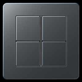
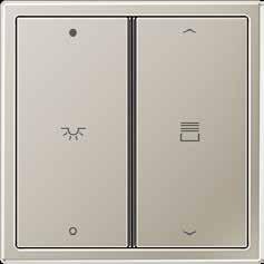
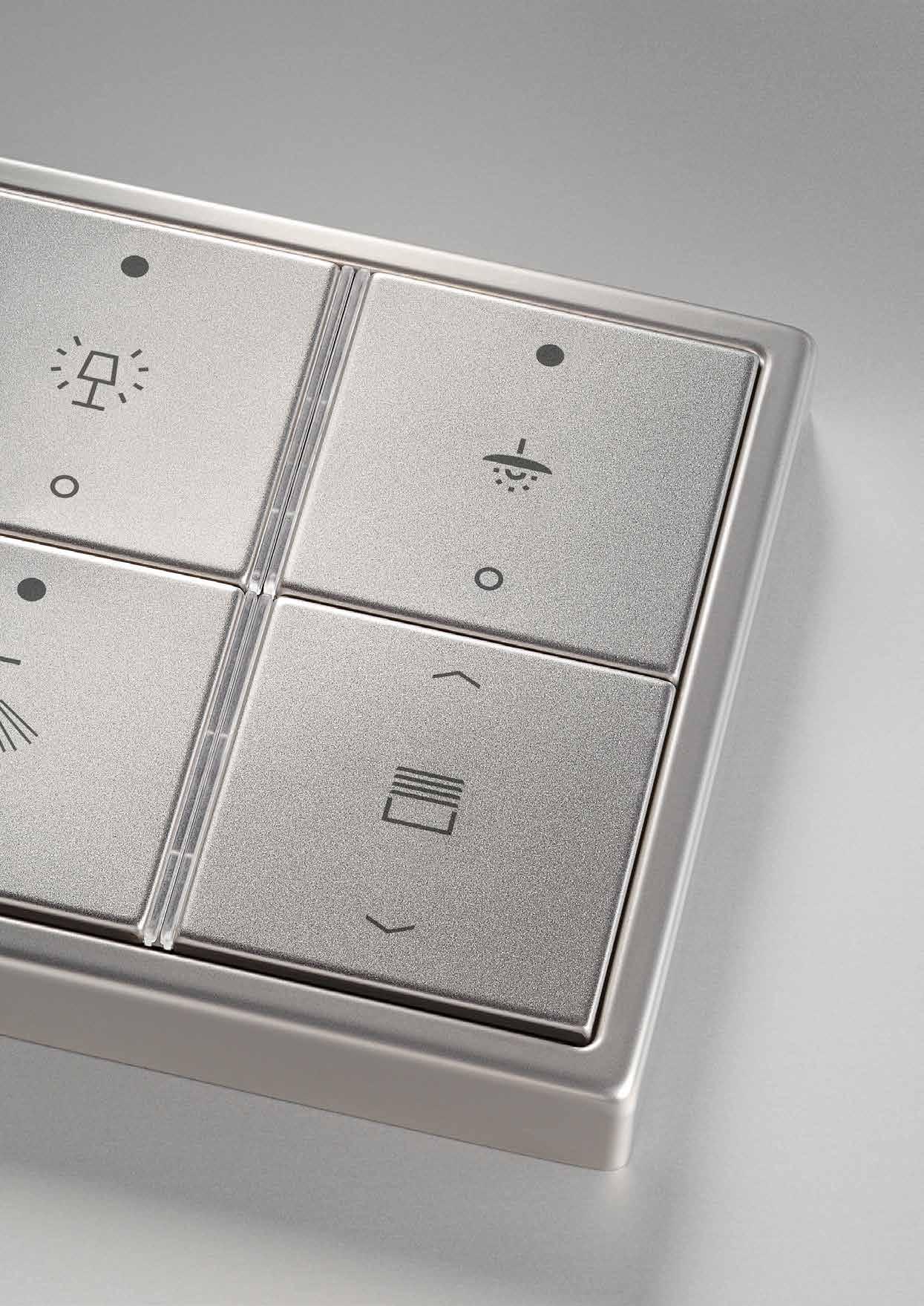
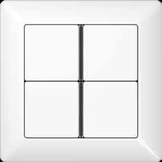
The F 40 family
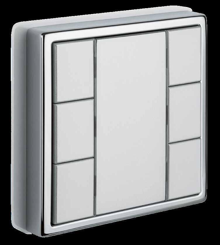
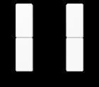
Easy operating concept meets straight line design: The KNX sensors of the F 40 family focus on large, square centre plates for convenient use.


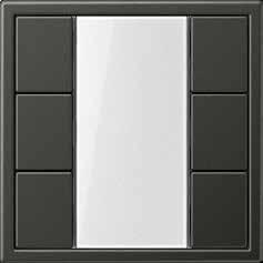
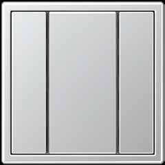
PUSH-BUTTON SENSORS
Thanks to the large buttons, a simple and convenient operating concept for control of functions and scenes is produced for 1 to 4-gang F 40 push-button sensors.
PUSH-BUTTON SENSORS RF
KNX RF is the manufacturer-independent KNX wireless standard. The RF push-button sensors have the same operating concept and design as the well-known push-button sensors with twisted pair connection.
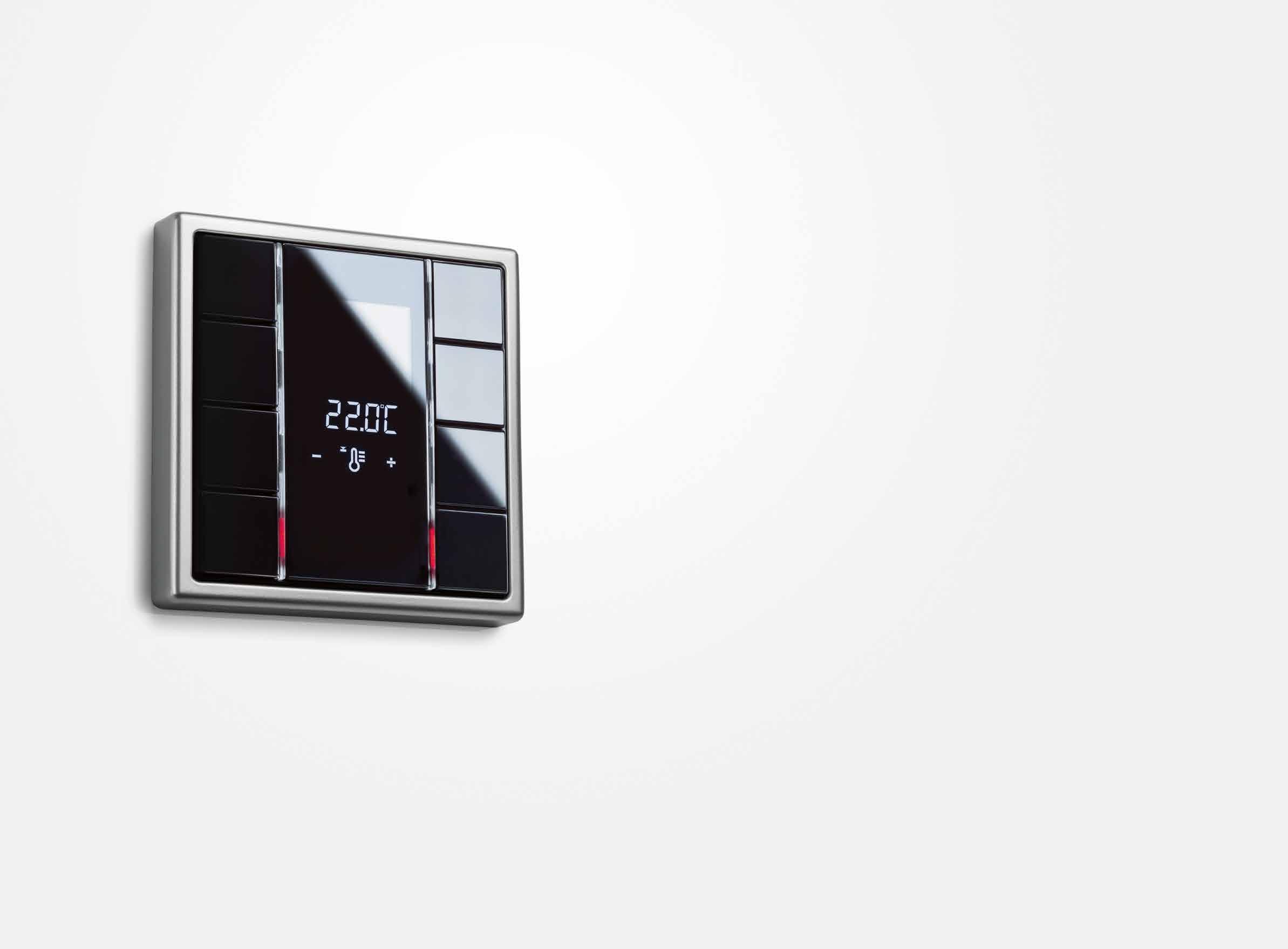
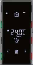
COMPACT ROOM CONTROLLER
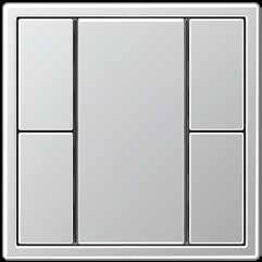
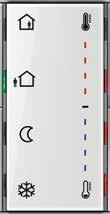
The room functions and scenes are controlled with the room controllers of the F 40 family using the large operating buttons. Status and function selection are shown on the graphical display. Centrally arranged, coloured LEDs for operation and status display round off the easy handling. With three control panels for switching, sensing, dimming or blind control The preset functions are executed using the markings on the left and right on the display; the buttons can be freely parametrised.
Push-button sensor F 40 LS 990 in stainless steel PUSH-BUTTON SENSORS/ROOM CONTROLLERS 55 54 PUSH-BUTTON SENSORS/ROOM CONTROLLERS
Individual button assignment
ONE-BUTTON OPERATION
ONE-BUTTON OPERATION
with one function per button.
with two functions per button.
TWO-BUTTON OPERATION
with two functions per button.
TWO-BUTTON OPERATION with four functions per button.
One-button or two-button operation can be set as operating modes for the F 40 push-button sensors. One operating button can be configured in each case as rocker or button function. For the rocker function, an operating button is divided into two operating pressure points with the same basic function. For the button function, on the other hand, an operating button features two control points with individually programmable functions.
Push-button sensor F 40
LS CUBE in aluminium
OFF/ON OFF/ON PUSH-BUTTON SENSORS/ROOM CONTROLLERS 57 56 PUSH-BUTTON SENSORS/ROOM CONTROLLERS
Versatile functionality
With regard to design and operating concept, the F 40 push-button sensors come close to a conventional switch. This also makes the handling easy for users not used to KNX. The large areas can be labelled easily and clearly recognisable that further optimises the operation using the Graphic Tool.
EXTENSION MODULE CONNECTION*
The flat push-button extension module can be directly connected to the main module for flexible extension of the functions. It is mounted in a 2-gang frame using a special supporting ring. Advantage also for the retrofitting. No separate flush-mounted box is needed.
THE CONSTRUCTION SITE COVERAGE
Thanks to the construction site coverage, button and function assignment can already be realised in construction site operation. The decision for button and cover design thus has time until the project acceptance.
PUSH-BUTTON QUICK MOUNTING
The operating buttons are provided as complete Cover kit on a mounting aid for quick mounting. Each button can also be individually replaced, e.g. for a laser-cut or printed version.
INTEGRATED: THE TEMPERATURE SENSOR*
The temperature at a different place in the room can be measured with the temperature sensor. The values are transmitted to the room temperature controller or room controller for effective control.
ENLIGHTENING: THE LIGHT SCENE MEMORY*
Up to 8 light scenes can be stored in the integrated light scene memory; in turn, eight groups can be assigned to each scene. They can be recalled using the buttons or other KNX commands.
Push-button sensor F 40 LS 990 in Dark
PUSH-BUTTON SENSORS/ROOM CONTROLLERS 59 58 PUSH-BUTTON SENSORS/ROOM CONTROLLERS * only for Universal version
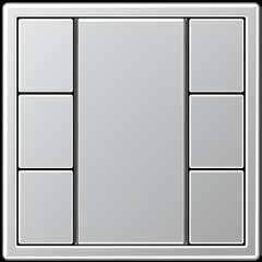
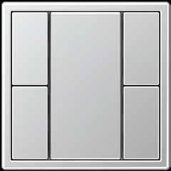
Variety of designs
The AS, A, CD and LS ranges give the KNX sensors of the F 40 family their attractive appearance. Genuine materials, distinctive forms and a wide variety of colours determine the JUNG design. They can be matched to any ambiance.


Push-button sensor F 40 LS ZERO in aluminium in white in white in white in white LS 990 A FLOW CD 500 AS 500 PUSH-BUTTON SENSORS/ROOM CONTROLLERS 61 60 PUSH-BUTTON SENSORS/ROOM CONTROLLERS
F 40 – numerous combination possibilities


Flexibility for the planning: There are identical modules as the basis for all design variants for the KNX F 40 push-button sensors. Thus, the switch program can still be selected after the installation. The corresponding cover kits and frames are available in the JUNG design ranges.


1
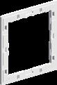
Supporting ring
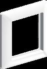
2 Frame
3 1-gang adapter frame
5
kit 1-gang 4 5 A CD LS 2-gang 3-gang A CD LS A CD LS 4-gang A CD LS 1 2 CD 500 CD PLUS CD adapter frame 3 CD RANGE 2 A FLOW A CREATION THE A 550 AS 500 AS AND A RANGES 2 LS DESIGN LS RANGE LS PLUS LS ZERO LS 990 LS adapter frame 3 PUSH-BUTTON SENSORS/ROOM CONTROLLERS 63 62 PUSH-BUTTON SENSORS/ROOM CONTROLLERS
4 Push-button module
Cover
Ref.-no.
KNX standard push-button module
Adapter frames are included in delivery: ref.-no. LS 4 AR for LS range (pre-mounted) and ref.-no. CD 4 AR for CD range. AS / A ranges without adapter frame. Only with the ETS 3.0d version or later versions the full functionality will be available.
Intended use
• Operation of loads, e.g. light on/off, dimming, blinds up/down, calling up and saving light scenes, etc.
• Installation in flush box according to DIN 49073
Product characteristics
• KNX medium: TP 256
• Push-button functions switching, dimming, blind control, value transmitter, scene recall, etc.
• To be completed with cover kit
• One red status LED per button
• One blue operation LED as an orientation light and to indicate the programming status
• Integrated bus coupling unit
• Transparent cover kit (included) for temporary site use without design covers
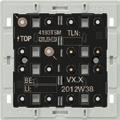
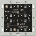
KNX standard push-button module, 1-gang for cover kit 1-gang, ref.-no.: .. 401 TSA .. for cover 1-gang with symbols, ref.-no.: .. 401 TSAP ..
ETS product family: Push-button
Product type: 1-gang push-button
1 blue LED: operation indication
1 red LED: status indication
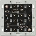
KNX standard push-button module, 2-gang for cover kit 2-gang, ref.-no.: .. 402 TSA .. for cover 2-gang with symbols, ref.-no.: .. 402 TSAP ..
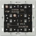
ETS product family: Push-button
Product type: 2-gang push-button
1 blue LED: operation indication
2 red LED: status indication
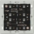
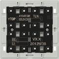
KNX standard push-button module, 3-gang for cover kit 3-gang, ref.-no.: .. 403 TSA .. for cover 2-gang with symbols, ref.-no.: .. 402 TSAP .. for cover 4-gang with symbols, ref.-no.: .. 404 TSAP ..
ETS product family: Push-button
Product type: 3-gang push-button
1 blue LED: operation indication
3 red LED: status indication
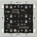
KNX standard push-button module, 4-gang for cover kit 4-gang, ref.-no.: .. 404 TSA .. for cover 4-gang with symbols, ref.-no.: .. 404 TSAP ..
ETS product family: Push-button
Product type: 4-gang push-button
1 blue LED: operation indication
4 red LED: status indication
4071 TSM
4072 TSM
4073 TSM
4074 TSM
64 KNX F 40
Ref.-no. KNX F 40
KNX universal push-button module can be extended by means of a push-button extension module, ref.-no.: 409.. TSEM Adapter frames are included in delivery: ref.-no. LS 4 AR for LS range (pre-mounted) and ref.-no. CD 4 AR for CD range. AS / A ranges without adapter frame. Only with the ETS 3.0d version or later versions the full functionality will be available.
Intended use
• Operation of loads, e.g. light on/off, dimming, blinds up/down, brightness values, temperatures, calling up and saving light scenes, etc.
• Installation in flush box according to DIN 49073
Product characteristics
• KNX medium: TP 256
• Push-button functions switching, dimming, blind control, value transmitter, scene recall, etc.
• Measurement of room temperature
• To be completed with cover kit
• Two red status LEDs per button
• One blue operation LED as an orientation light and to indicate the programming status
• Integrated bus coupling unit
• One, two or three functions per button
• Push-button function or rocker function, vertical or horizontal
• Connection for a push-button extension module, 1-4 gang
KNX universal push-button module, 1-gang for cover kit 1-gang, ref.-no.: .. 401 TSA .. for cover 1-gang with symbols, ref.-no.: .. 401 TSAP ..
ETS product family: Push-button
Product type: 1-gang push-button
1 blue LED: operation indication
2 red LED: status indication
KNX universal push-button module, 2-gang for cover kit 2-gang, ref.-no.: .. 402 TSA .. for cover 2-gang with symbols, ref.-no.: .. 402 TSAP ..
Product type: 2-gang push-button
1 blue LED: operation indication
4 red LED: status indication
KNX universal push-button module, 3-gang for cover kit 3-gang, ref.-no.: .. 403 TSA .. for cover 2-gang with symbols, ref.-no.: .. 402 TSAP .. for cover 4-gang with symbols, ref.-no.: .. 404 TSAP ..
Product type: 3-gang push-button
1 blue LED: operation indication
6 red LED: status indication
KNX universal push-button module, 4-gang for cover kit 4-gang, ref.-no.: .. 404 TSA .. for cover 4-gang with symbols, ref.-no.: .. 404 TSAP ..
Product type: 4-gang push-button
1 blue LED: operation indication
8 red LED: status indication
4191 TSM
4192 TSM
4193 TSM
4194 TSM
• Transparent cover kit (included) for temporary site use without design covers 65
ETS product family: Push-button
ETS product family: Push-button
ETS product family: Push-button
KNX AS range and A range


F 40
Delivery of cover kits: 1 complete set per ref.-no.!
Push-button extension module for the extension of up to 4 additional push-buttons for the devices:
• Universal push-button module (ref.-no. 419.. TSM)
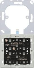
• Room controller display compact module (ref.-no. 4093 KRM TS D)
• Room controller display module 2-gang preferred installation: vertical Adapter frames are included in delivery: ref.-no. LS 4 AR for LS range (pre-mounted) and ref.-no. CD 4 AR for CD range.
AS / A ranges without adapter frame. red LED: status indication
Ref.-no.
Cover kits for AS and A ranges
Cover kit 1-gang
to clip on F 40 push-button modules 1-gang
ref.-no.: 4071 TSM, 4191 TSM, 4091 TSEM, 4071 RF TSM, 4212 TSM, 4008 TSM, FM 4001 M
Thermoplastic (breakproof) high-gloss
(breakproof) lacquered
matt lacquered
401 TSA MO
Cover kit 2-gang
to clip on F 40 push-button modules 2-gang
ref.-no.: 4072 TSM, 4192 TSM, 4092 TSEM, 4072 RF TSM, 4224 TSM, 4008 TSM, FM 4002 M
Thermoplastic (breakproof) high-gloss
ivory L A 402 TSA
white
L A 402 TSA WW
black L A 402 TSA SW
Thermoplastic (breakproof) lacquered
mocha
matt lacquered
matt graphite black
matt anthracite
402 TSA AL
402 TSA CH
402 TSA MO
66
1-gang 4091 TSEM 2-gang 4092 TSEM 3-gang 4093 TSEM 4-gang 4094 TSEM
ivory L A 401 TSA white L A 401 TSA WW black L A 401 TSA SW
aluminium P L A 401 TSA AL champagne P A 401 TSA CH mocha A
Thermoplastic
matt snow white N A 401 TSA WWM
matt graphite black N A 401 TSA SWM
matt anthracite A 401 TSA ANM
A
aluminium P L A
champagne P
A
matt snow white N A 402 TSA WWM
A
N
402 TSA SWM
A 402 TSA ANM
range and A range
Delivery of cover kits: 1 complete set per ref.-no.!
Cover kit 3-gang
to clip on F 40 push-button modules 3-gang
ref.-no.: 4073 TSM, 4193 TSM, 4093 TSEM, 4073 RF TSM, 4236 TSM, 4008 TSM, FM 4003 M
Thermoplastic (breakproof) high-gloss
Thermoplastic (breakproof) lacquered
Cover kit 4-gang
to clip on F 40 push-button modules 4-gang ref.-no.: 4074 TSM, 4194 TSM, 4094 TSEM, 4074 RF TSM, 4248 TSM, 4008 TSM, FM 4004 M


Thermoplastic (breakproof) high-gloss
Thermoplastic (breakproof) lacquered
Professional laser inscription and colour printing! For further information see www.jung.de/gt
Covers with symbols for AS and A ranges
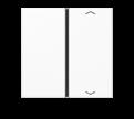
Cover 1-gang
with symbols ▲▼ to clip on F 40 push-button modules 1-gang
ref.-no.: 4071 TSM, 4191 TSM, 4091 TSEM, 4071 RF TSM, 4212 TSM, 4008 TSM, FM 4001 M
Thermoplastic (breakproof) high-gloss
Thermoplastic (breakproof)
Ref.-no. 67 KNX
AS
F 40
ivory L A 403 TSA white L A 403 TSA WW black L A 403 TSA SW
aluminium P L A 403 TSA AL champagne P A 403 TSA CH mocha A 403 TSA MO matt lacquered matt snow white N A 403 TSA WWM matt graphite black N A 403 TSA SWM matt anthracite A 403 TSA ANM
ivory L A 404 TSA white L A 404 TSA WW black L A 404 TSA SW
aluminium P L A 404 TSA AL champagne P A 404 TSA CH mocha A 404 TSA MO matt lacquered matt snow white N A 404 TSA WWM matt graphite black N A 404 TSA SWM matt anthracite A 404 TSA ANM
A 401 TSAP white A 401 TSAP WW black A 401 TSAP SW
ivory
aluminium A 401 TSAP AL champagne A 401 TSAP CH mocha A 401 TSAP MO
lacquered matt anthracite A 401 TSAP ANM
lacquered
matt
KNX AS range and A range


F 40
Ref.-no.
Cover 2-gang with symbols ▲▼
to exchange the covers of the cover kit 2-gang ref.-no.: A 402 TSA.. and the right cover of the cover kit 3-gang ref.-no.: A 403 TSA..
Thermoplastic (breakproof) high-gloss
ivory
Thermoplastic (breakproof) lacquered
Cover 4-gang with symbols ▲▼ to exchange the top left cover of the cover kit 3-gang ref.-no.: A 403 TSA.. and top left and bottom right cover of the cover kit 4-gang ref.-no.: A 404 TSA..
Thermoplastic (breakproof) high-gloss ivory
Thermoplastic (breakproof) lacquered
Cover 4-gang with symbols ▲▼ to exchange the bottom left cover of the cover kit 3-gang ref.-no.: A 403 TSA.. and top right and bottom left cover of the cover kit 4-gang ref.-no.: A 404 TSA..
Thermoplastic (breakproof) high-gloss ivory
Thermoplastic (breakproof) lacquered
68
A 402 TSAP
A 402 TSAP WW
A 402 TSAP SW
white
black
A 402 TSAP AL champagne A 402 TSAP CH
A 402 TSAP MO
lacquered matt anthracite A 402 TSAP ANM
aluminium
mocha
matt
A 404 TSAP 14
A 404 TSAP WW 14
A 404 TSAP SW 14
white
black
aluminium A 404 TSAP AL 14 champagne A 404 TSAP CH 14
A 404 TSAP MO 14
lacquered
anthracite A 404 TSAP ANM 14
mocha
matt
matt
A 404 TSAP 23
A 404 TSAP WW 23 black A 404 TSAP SW
white
23
aluminium A 404 TSAP AL 23 champagne A 404 TSAP CH 23 mocha A 404 TSAP MO 23 matt lacquered matt anthracite A 404 TSAP ANM 23
Delivery of cover kits: 1 complete set per ref.-no.!
Cover kits for CD range


Cover kit 1-gang
to clip on F 40 push-button modules 1-gang
Ref.-no.
ref.-no.: 4071 TSM, 4191 TSM, 4091 TSEM, 4071 RF TSM, 4212 TSM, 4008 TSM, FM 4001 M
Thermoplastic (breakproof) high-gloss
ivory
white
grey
light grey
black
Cover kit 2-gang
to clip on F 40 push-button modules 2-gang
L CD 401 TSA
L CD 401 TSA WW
L CD 401 TSA GR
L CD 401 TSA LG
L CD 401 TSA SW
ref.-no.: 4072 TSM, 4192 TSM, 4092 TSEM, 4072 RF TSM, 4224 TSM, 4008 TSM, FM 4002 M
Thermoplastic (breakproof) high-gloss
ivory
white
grey
light grey
black
Cover kit 3-gang
to clip on F 40 push-button modules 3-gang
L CD 402 TSA
L CD 402 TSA WW
L CD 402 TSA GR
L CD 402 TSA LG
L CD 402 TSA SW
ref.-no.: 4073 TSM, 4193 TSM, 4093 TSEM, 4073 RF TSM, 4236 TSM, 4008 TSM, FM 4003 M
Thermoplastic (breakproof) high-gloss
ivory
white
grey
light grey
black
Cover kit 4-gang
to clip on F 40 push-button modules 4-gang
L CD 403 TSA
L CD 403 TSA WW
L CD 403 TSA GR
L CD 403 TSA LG
L CD 403 TSA SW
ref.-no.: 4074 TSM, 4194 TSM, 4094 TSEM, 4074 RF TSM, 4248 TSM, 4008 TSM, FM 4004 M
Thermoplastic (breakproof) high-gloss
ivory
white

grey
light grey
black
Professional laser inscription and colour printing! For further information see www.jung.de/gt
L CD 404 TSA
L CD 404 TSA WW
L CD 404 TSA GR
L CD 404 TSA LG
L CD 404 TSA SW
69
F 40
KNX CD range
KNX CD range F 40
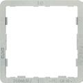

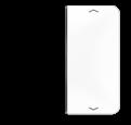
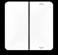
Delivery of cover kits: 1 complete set per ref.-no.!
Covers with symbols for CD range
Cover 1-gang with symbols ▲▼
Ref.-no.
to clip on F 40 push-button modules 1-gang ref.-no.: 4071 TSM, 4191 TSM, 4091 TSEM, 4071 RF TSM, 4212 TSM, 4008 TSM, FM 4001 M

Thermoplastic (breakproof) high-gloss
ivory
white
grey
light grey
black
Cover 2-gang with symbols ▲▼
to exchange the covers of the cover kit 2-gang ref.-no.: CD 402 TSA.. and the right cover of the cover kit 3-gang ref.-no.: CD 403 TSA..
Thermoplastic (breakproof) high-gloss
ivory
white
grey
light grey
black
Cover 4-gang with symbols ▲▼
to exchange the top left cover of the cover kit 3-gang ref.-no.: CD 403 TSA.. and top left and bottom right cover of the cover kit 4-gang ref.-no.: CD 404 TSA..
Thermoplastic (breakproof) high-gloss
ivory
white
grey
light grey
black
Cover 4-gang with symbols ▲▼ to exchange the bottom left cover of the cover kit 3-gang ref.-no.: CD 403 TSA.. and top right and bottom left cover of the cover kit 4-gang ref.-no.: CD 404 TSA..
Thermoplastic (breakproof) high-gloss
ivory
white
grey
light grey
black
Adapter frame (Spare part)
to combine push-button modules with CD range Also included in delivery of modules.
CD 401 TSAP
CD 401 TSAP WW
CD 401 TSAP GR
CD 401 TSAP LG
CD 401 TSAP SW
CD 402 TSAP
CD 402 TSAP WW
CD 402 TSAP GR
CD 402 TSAP LG
CD 402 TSAP SW
CD 404 TSAP 14
CD 404 TSAP WW 14
CD 404 TSAP GR 14
CD 404 TSAP LG 14
CD 404 TSAP SW 14
CD 404 TSAP 23
CD 404 TSAP WW 23
CD 404 TSAP GR 23
CD 404 TSAP LG 23
CD 404 TSAP SW 23
CD 4 AR
70
Delivery of cover kits: 1 complete set per ref.-no.!
Cover kits for LS range
Cover kit 1-gang
to clip on F 40 push-button modules 1-gang
ref.-no.: 4071 TSM, 4191 TSM, 4091 TSEM, 4071 RF TSM, 4212 TSM, 4008 TSM, FM 4001 M
Thermoplastic (breakproof) high-gloss
ivory
white
light grey
matt lacquered
matt snow white
matt
metal versions
aluminium
stainless steel
anthracite (aluminium lacquered)
dark (aluminium lacquered)
classic brass
antique brass
Cover kit 2-gang
to clip on F 40 push-button modules 2-gang
L LS 401 TSA
L LS 401 TSA WW
L LS 401 TSA LG
P L AL 2401 TSA
L ES 2401 TSA
AL 2401 TSA AN
AL 2401 TSA D
P ME 2401 TSA C
ME 2401 TSA AT
ref.-no.: 4072 TSM, 4192 TSM, 4092 TSEM, 4072 RF TSM, 4224 TSM, 4008 TSM, FM 4002 M
Thermoplastic (breakproof) high-gloss
ivory
light grey L LS 402 TSA LG
matt lacquered
aluminium
stainless steel L ES 2402 TSA
anthracite (aluminium lacquered) AL 2402 TSA AN
dark (aluminium lacquered)
classic brass
antique brass
AL 2402 TSA D
P ME 2402 TSA C
ME 2402 TSA AT
71 KNX LS range F 40
Ref.-no.
black L LS 401 TSA SW
N
LS 401 TSA WWM
graphite black N LS 401 TSA SWM
L LS 402 TSA white L LS 402 TSA WW
black L LS 402 TSA SW
N
matt snow white
LS 402 TSA WWM
N LS
SWM
matt graphite black
402 TSA
metal versions
P L AL 2402 TSA
KNX LS range F 40
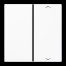


Delivery of cover kits: 1 complete set per ref.-no.!
Cover kit 3-gang
to clip on F 40 push-button modules 3-gang
Ref.-no.
ref.-no.: 4073 TSM, 4193 TSM, 4093 TSEM, 4073 RF TSM, 4236 TSM, 4008 TSM, FM 4003 M
Thermoplastic (breakproof) high-gloss
LS 403 TSA white
ivory
LS 403 TSA WW light grey
LS 403 TSA SW
LS 403 TSA LG black
matt lacquered
matt snow white
aluminium
stainless steel
LS 403 TSA SWM
LS 403 TSA WWM matt graphite black
AL 2403 TSA
ES 2403 TSA
2403 TSA AN dark (aluminium lacquered)
anthracite (aluminium lacquered)
classic brass
antique brass
Cover kit 4-gang
to clip on F 40 push-button modules 4-gang
2403 TSA D
ME 2403 TSA C
2403 TSA AT
ref.-no.: 4074 TSM, 4194 TSM, 4094 TSEM, 4074 RF TSM, 4248 TSM, 4008 TSM, FM 4004 M
Thermoplastic (breakproof) high-gloss
ivory
white
light grey
black
matt lacquered
matt snow white
matt graphite black
metal versions
aluminium
stainless steel
anthracite (aluminium lacquered)
dark (aluminium lacquered)
classic brass
antique brass
Professional laser inscription and colour printing! For further information see www.jung.de/gt
Covers with symbols for LS range
Cover 1-gang
with symbols ▲▼
to clip on F 40 push-button modules 1-gang
LS 404 TSA
L LS 404 TSA WW
L LS 404 TSA LG
L LS 404 TSA SW
N LS 404 TSA WWM
N LS 404 TSA SWM
P L AL 2404 TSA
L ES 2404 TSA
AL 2404 TSA AN
AL 2404 TSA D
P ME 2404 TSA C
ME 2404 TSA AT
ref.-no.: 4071 TSM, 4191 TSM, 4091 TSEM, 4071 RF TSM, 4212 TSM, 4008 TSM, FM 4001 M
Thermoplastic (breakproof) high-gloss
ivory LS 401 TSAP
white LS 401 TSAP WW
light grey LS 401 TSAP LG
black LS 401 TSAP SW
metal versions
aluminium
stainless steel
anthracite (aluminium lacquered)
dark (aluminium lacquered)
AL 2401 TSAP
ES 2401 TSAP
AL 2401 TSAP AN
AL 2401 TSAP D
72
L
L
L
L
N
N
metal
versions
P L
L
AL
AL
P
ME
L
Ref.-no.
Cover 2-gang with symbols ▲▼
to exchange the covers of the cover kit 2-gang ref.-no.: ..402 TSA.. and the right cover of the cover kit 3-gang ref.-no.: ..403 TSA.. in the LS range
Thermoplastic (breakproof) high-gloss
ivory
white
light grey
black
metal versions
aluminium
stainless steel
anthracite (aluminium lacquered)
dark (aluminium lacquered)
classic brass
antique brass
Cover 4-gang
with symbols ▲▼
LS 402 TSAP
LS 402 TSAP WW
LS 402 TSAP LG
LS 402 TSAP SW
AL 2402 TSAP
ES 2402 TSAP
AL 2402 TSAP AN
AL 2402 TSAP D
ME 2402 TSAP C
ME 2402 TSAP AT
to exchange the top left cover of the cover kit 3-gang ref.-no.: ..403 TSA.. and top left and bottom right cover of the cover kit 4-gang ref.-no.: ..404 TSA.. in the LS range
Thermoplastic (breakproof) high-gloss
ivory
white
light grey
black
metal versions
aluminium
stainless steel
anthracite (aluminium lacquered)
dark (aluminium lacquered)
classic brass
antique brass
Cover 4-gang with symbols ▲▼
LS 404 TSAP 14
LS 404 TSAP WW 14
LS 404 TSAP LG 14
LS 404 TSAP SW 14
AL 2404 TSAP 14
ES 2404 TSAP 14
AL 2404 TSAP AN 14
AL 2404 TSAP D 14
ME 2404 TSAP C 14
ME 2404 TSAP AT 14
to exchange the bottom left cover of the cover kit 3-gang ref.-no.: ..403 TSA.. and top right and bottom left cover of the cover kit 4-gang ref.-no.: ..404 TSA.. in the LS range
Thermoplastic (breakproof) high-gloss
ivory
white
light grey
black
metal versions
aluminium
stainless steel
anthracite (aluminium lacquered)
dark (aluminium lacquered)
classic brass
antique brass
Adapter frame (Spare part)
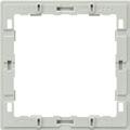


to combine push-button modules with LS range Also included in delivery of modules.
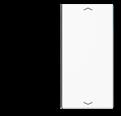
LS 404 TSAP 23
LS 404 TSAP WW 23
LS 404 TSAP LG 23
LS 404 TSAP SW 23
AL 2404 TSAP 23
ES 2404 TSAP 23
AL 2404 TSAP AN 23
AL 2404 TSAP D 23
ME 2404 TSAP C 23
ME 2404 TSAP AT 23
LS 4 AR
73 KNX LS range F 40
Ref.-no.
KNX room controller display compact module can be extended by means of a push-button extension module, ref.-no.: 409.. TSEM Adapter frames are included in delivery: ref.-no. LS 4 AR for LS range (pre-mounted) and ref.-no. CD 4 AR for CD range. AS / A ranges without adapter frame.
4093 KRM TS D
Intended use
• Measurement and feedback control of the room temperature
• Operation of loads, e.g. light on/off, dimming, blinds up/down, brightness values, temperatures, calling up and saving light scenes, etc.
• Installation in flush box according to DIN 49073
Product characteristics
All buttons can be assigned with push-button sensor functions or functions for controller operation.
• KNX medium: TP 256
• Four red status LEDs
• One blue operation LED as an orientation light and to indicate the programming status
• Integrated bus coupling unit
• Connection for a push-button extension module, 1-4 gang
• Integrated temperature sensor
• Room temperature control with setpoint value specification
• Display of room or set temperature
• Display of outdoor temperature – with external sensor, e.g. weather station
• Display of time, in conjunction with KNX time encoder
• Push-button functions switching, dimming, blind control, value transmitter, scene recall, etc.
• Push-button function or rocker function, vertical or horizontal
• Fan coil application with up to 8 fan speeds and auto function
• Transparent cover kit (included) for temporary site use without design covers
Technical data
Recommended mounting height: 1.5 m
Push-button extension module for the extension of up to 4 additional push-buttons for the devices:
• Universal push-button module (ref.-no. 419.. TSM)
• Room controller display compact module (ref.-no. 4093 KRM TS D)
• Room controller display module 2-gang preferred installation: vertical Adapter frames are included in delivery: ref.-no. LS 4 AR for LS range (pre-mounted) and ref.-no. CD 4 AR for CD range. AS / A ranges without adapter frame. red LED: status indication
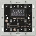
74 KNX F 40
1-gang 4091 TSEM 2-gang 4092 TSEM 3-gang 4093 TSEM 4-gang 4094 TSEM
F 40
Delivery of cover kits: 1 complete set per ref.-no.!

Cover kits for AS and A ranges
Cover kit to clip on room controller display compact module ref.-no.: 4093 KRM TS D

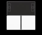
Thermoplastic (breakproof) high-gloss ivory
Thermoplastic (breakproof) lacquered
KNX
AS and A ranges
Professional laser inscription and colour printing! For further information see www.jung.de/gt
Cover with temperature symbol to exchange the display cover of the cover kit ref.-no.: A 4093 TSA..
Thermoplastic (breakproof) high-gloss
Cover 4-gang with symbols ▲▼ to exchange the bottom right cover of the cover kit ref.-no.: A 4093 TSA..
Thermoplastic (breakproof) high-gloss
Thermoplastic (breakproof) lacquered
Cover 4-gang with symbols ▲▼ to exchange the bottom left cover of the cover kit ref.-no.: A 4093 TSA..
Thermoplastic (breakproof) high-gloss ivory
Thermoplastic (breakproof) lacquered
Ref.-no. 75
L A 4093
L A 4093
WW
L A 4093 TSA SW
TSA white
TSA
black
aluminium P L A 4093 TSA AL champagne P A 4093 TSA CH mocha A 4093 TSA MO matt lacquered matt snow white N A 4093 TSA WWM matt graphite black N A 4093 TSA SWM matt anthracite A 4093 TSA ANM
A 409 T
ivory A 404 TSAP 14 white A 404 TSAP WW 14 black A 404 TSAP SW 14
A 404 TSAP AL 14 champagne A 404 TSAP CH 14 mocha A 404 TSAP MO 14
lacquered matt
A 404 TSAP ANM 14
aluminium
matt
anthracite
A 404 TSAP 23
A 404 TSAP WW 23
A 404 TSAP SW 23
white
black
A 404 TSAP AL 23 champagne A 404 TSAP CH 23 mocha A 404 TSAP MO 23
matt anthracite A 404 TSAP ANM 23
aluminium
matt lacquered
KNX CD range F 40

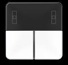
Delivery of cover kits: 1 complete set per ref.-no.!
Cover kits for CD range
Cover kit to clip on room controller display compact module ref.-no.: 4093 KRM TS D
Thermoplastic (breakproof) high-gloss
Ref.-no.

ivory L CD 4093 TSA
white L CD 4093 TSA WW
grey L CD 4093 TSA GR
light grey
black
Professional laser inscription and colour printing! For further information see www.jung.de/gt
Cover with temperature symbol to exchange the display cover of the cover kit ref.-no.: CD 4093 TSA..
Thermoplastic (breakproof) high-gloss
Cover 4-gang with symbols ▲▼ to exchange the bottom right cover of the cover kit ref.-no.: CD 4093 TSA..
Thermoplastic (breakproof) high-gloss
ivory
white
grey
light grey
black
Cover 4-gang with symbols ▲▼ to exchange the bottom left cover of the cover kit ref.-no.: CD 4093 TSA..
Thermoplastic (breakproof) high-gloss
ivory
white
grey
light grey
CD 4093 TSA LG
CD 4093 TSA SW
CD 409 T
CD 404 TSAP 14
CD 404 TSAP WW 14
CD 404 TSAP GR 14
CD 404 TSAP LG 14
CD 404 TSAP SW 14
CD 404 TSAP 23
CD 404 TSAP WW 23
CD 404 TSAP GR 23
CD 404 TSAP LG 23
black CD 404 TSAP SW 23
Adapter frame (Spare part)
to combine push-button modules with CD range Also included in delivery of modules.
CD 4 AR
76
L
L
Delivery of cover kits: 1 complete set per ref.-no.!
Cover kits for LS range
Cover kit to clip on room controller display compact module ref.-no.: 4093 KRM TS D
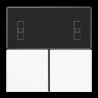
Thermoplastic (breakproof) high-gloss
ivory
white
light grey
black
matt lacquered
matt snow white
matt graphite black
metal versions
aluminium
stainless steel
anthracite (aluminium lacquered)
dark (aluminium lacquered)
classic brass
antique brass
Professional laser inscription and colour printing! For further information see www.jung.de/gt
Ref.-no.

L LS 4093 TSA
L LS 4093 TSA WW
L LS 4093 TSA LG
L LS 4093 TSA SW
N LS 4093 TSA WWM
N LS 4093 TSA SWM
P
L AL 4093 TSA
L ES 4093 TSA
AL 4093 TSA AN
AL 4093 TSA D
P ME 4093 TSA C
ME 4093 TSA AT
Cover with temperature symbol to exchange the display cover of the cover kit ref.-no.: .. 4093 TSA .. in the LS range
Thermoplastic (breakproof) high-gloss
LS 409 T
Cover 4-gang with symbols ▲▼ to exchange the bottom right cover of the cover kit ref.-no.: .. 4093 TSA .. in the LS range
Thermoplastic (breakproof) high-gloss
ivory LS 404 TSAP 14
white
light grey
black
metal versions page 73
LS 404 TSAP WW 14
LS 404 TSAP LG 14
LS 404 TSAP SW 14
Cover 4-gang with symbols ▲▼ to exchange the bottom left cover of the cover kit ref.-no.: .. 4093 TSA .. in the LS range
Thermoplastic (breakproof) high-gloss
ivory LS 404 TSAP 23
white LS 404 TSAP WW 23
light grey LS 404 TSAP LG 23
black LS 404 TSAP SW 23
metal versions page 73
Adapter frame (Spare part) to combine push-button modules with LS range Also included in delivery of modules.

LS 4 AR

77
LS
F 40
KNX
range
KNX RF
KNX WIRELESS MEDIA COUPLER KNX HAND-HELD RADIO TRANSMITTERS
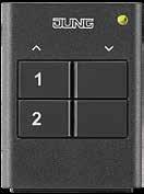
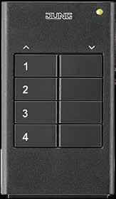
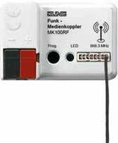
KNX F 40 WALL-MOUNTED TRANSMITTER KNX F 50 WALL-MOUNTED TRANSMITTER
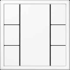
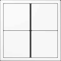
The KNX RF wireless standard in the JUNG design: wall-mounted transmitter in the F 50 and F 40 families – ideal for retrofitting and extending existing KNX installations. The KNX wall-mounted transmitters bridge structural conditions where no bus lines can or will be installed. In this way the especially flat devices can be flexibly located in the room as they are simply stuck on – whether on plaster, wood, or glass.
The room functions can be controlled conveniently with the press of a button in this way. Alternatively to the wall-mounted transmitters, the KNX hand-held radio transmitters are available. Any addressing, parametrising and diagnosing is carried out through the KNX wireless USB stick or if desired through the KNX data interface. The bi-directional connection of the KNX RF and wired KNX TP is established by the JUNG media coupler.
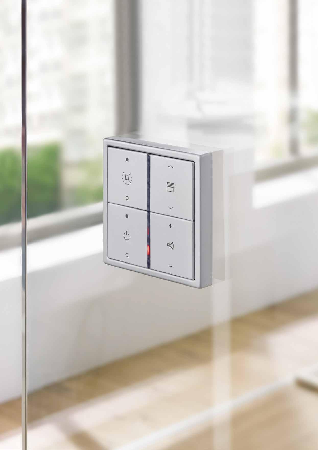 KNX F 40 hand-held radio transmitter in LS 990 in aluminium
in LS 990 in white
in 2-gang and 4-gang versions
in LS 990 in white
Interface between KNX RF and KNX TP
KNX F 40 hand-held radio transmitter in LS 990 in aluminium
in LS 990 in white
in 2-gang and 4-gang versions
in LS 990 in white
Interface between KNX RF and KNX TP
PUSH-BUTTON SENSORS/ROOM CONTROLLERS 79 78 PUSH-BUTTON SENSORS/ROOM CONTROLLERS
KNX RF AS range and A range
F 50
Ref.-no.
KNX RF radio transmitter modules F 50
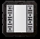
Intended use
• Radio operation of loads, e.g. light on/off, dimming, Venetian blinds up/down, brightness values, calling up and saving light scenes
• Operation in cabled KNX systems via radio converter (ref.-no.: MK 100 RF)
• Installation in flush box according to DIN 49073, screw fixing on walls or adhesive fixing on smooth, even surfaces (glass).
Product characteristics
• Push-button functions switching, dimming, blind control, value transmitter, scene recall, etc.
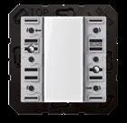
• Button pairs for push-button function or rocker function
• Status indication with LED
• Integrated temperature sensor
• Battery-powered device (battery compartment accessible from front)
• Project design and commissioning with ETS5 or a more recent version.
Technical data
Rated voltage: DC 3 V
Battery type: 1 x lithium CR 2450N (included)
Ambient temperature: −5 ... +45 °C
Radio frequency: 868.0 ... 868.6 MHz
Transmitting power: max. 20 mW
Transmission range in free field: typical 100 m
for AS and A ranges including mounting plate, adhesive pad and fastening screw including transparent cover ref.-no.: A 50 NA
KNX RF radio transmitter module 1-gang for cover kit 1-gang, ref.-no.: A 501 TSA ..
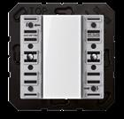
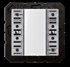
ETS product family: Push-button
Product type: 1-gang push-button
1 green LED: actuator status
1 red LED: transmission status
KNX RF radio transmitter module 2-gang for cover kit 2-gang, ref.-no.: A 502 TSA ..
ETS product family: Push-button
Product type: 2-gang push-button
2 green LED: actuator status
1 red LED: transmission status
KNX RF radio transmitter module 3-gang for cover kit 3-gang, ref.-no.: A 503 TSA ..
ETS product family: Push-button
Product type: 3-gang push-button
3 green LED: actuator status
1 red LED: transmission status
KNX RF radio transmitter module 4-gang for cover kit 4-gang, ref.-no.: A 504 TSA ..
ETS product family: Push-button
Product type: 4-gang push-button
4 green LED: actuator status
1 red LED: transmission status
Cover kits for AS and A ranges see as of page 40
A 5071 RF TSM
A 5072 RF TSM
A 5073 RF TSM
A 5074 RF TSM
80
KNX RF radio transmitter module 1-gang for cover kit 1-gang, ref.-no.: CD 501 TSA ..
ETS product family: Push-button
Product type: 1-gang push-button
1 green LED: actuator status
1 red LED: transmission status
KNX RF CD range F 50
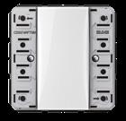
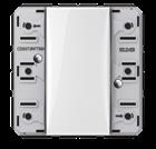
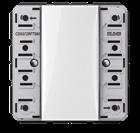
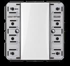
Ref.-no.
CD 5071 RF TSM
ETS product family: Push-button
Product type: 2-gang push-button
2 green LED: actuator status
1 red LED: transmission status
ETS product family: Push-button
Product type: 3-gang push-button
3 green LED: actuator status
1 red LED: transmission status
CD 5072 RF TSM
ETS product family: Push-button
Product type: 4-gang push-button
4 green LED: actuator status
1 red LED: transmission status
Cover kits for CD range see as of page 46
CD 5073 RF TSM
CD 5074 RF TSM
for CD range including mounting plate, adhesive pad and fastening screw including transparent cover ref.-no.: CD 50 NA 81
KNX RF radio transmitter module 2-gang for cover kit 2-gang, ref.-no.: CD 502 TSA ..
KNX RF radio transmitter module 3-gang for cover kit 3-gang, ref.-no.: CD 503 TSA ..
KNX RF radio transmitter module 4-gang for cover kit 4-gang, ref.-no.: CD 504 TSA ..
KNX RF radio transmitter modules F 50
KNX RF LS range F 50
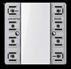
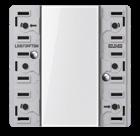
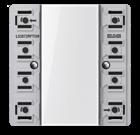
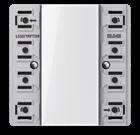
Ref.-no.
KNX RF radio transmitter modules F 50
for LS range including mounting plate, adhesive pad and fastening screw including transparent cover ref.-no.: LS 50 NA
KNX RF radio transmitter module 1-gang for cover kit 1-gang, ref.-no.: ..501 TSA .. in the LS range
Can not be combined with frames in FLAT DESIGN.
ETS product family: Push-button
Product type: 1-gang push-button
1 green LED: actuator status
1 red LED: transmission status
KNX RF radio transmitter module 2-gang for cover kit 2-gang, ref.-no.: LS 502 TSA ..
Can not be combined with frames in FLAT DESIGN.
ETS product family: Push-button
Product type: 2-gang push-button
2 green LED: actuator status
1 red LED: transmission status
KNX RF radio transmitter module 3-gang for cover kit 3-gang, ref.-no.: ..503 TSA .. in the LS range Can not be combined with frames in FLAT DESIGN.
ETS product family: Push-button
Product type: 3-gang push-button
3 green LED: actuator status
1 red LED: transmission status
KNX RF radio transmitter module 4-gang for cover kit 4-gang, ref.-no.: ..504 TSA .. in the LS range Can not be combined with frames in FLAT DESIGN.
ETS product family: Push-button
Product type: 4-gang push-button
4 green LED: actuator status
1 red LED: transmission status
Cover kits for LS range see as of page 51
LS 5071 RF TSM
LS 5072 RF TSM
LS 5073 RF TSM
LS 5074 RF TSM
82
Ref.-no.
KNX RF F 40
Intended use
• Radio operation of loads, e.g. light on/off, dimming, Venetian blinds up/down, brightness values, calling up and saving light scenes
• Operation in cabled KNX systems via radio converter (ref.-no.: MK 100 RF)
• Mounting on appliance box according to DIN 49073, screw fixing on walls or adhesive fixing on smooth, even surfaces (glass).
Product characteristics
• Push-button functions switching, dimming, blind control, value transmitter, scene recall, etc.
• Button pairs for push-button function or rocker function
• Status indication with LED
• Battery-powered device
• Project design and commissioning with ETS5 or a more recent version.
• Can not be combined with frames in FLAT DESIGN.
Technical data
Rated voltage: DC 3 V
Battery type: 1 x lithium CR 2450N (included)
Ambient temperature: −5 ... +45 °C
Radio frequency: 868.0 ... 868.6 MHz
Transmitting power: max. 20 mW
Transmission range in free field: typical 100 m
KNX RF radio transmitter module 1-gang for cover kit 1-gang, ref.-no.: .. 401 TSA .. for cover 1-gang with symbols, ref.-no.: .. 401 TSAP ..
ETS product family: Push-button
Product type: 1-gang push-button
1 red LED: actuator status
KNX RF radio transmitter module 2-gang for cover kit 2-gang, ref.-no.: .. 402 TSA .. for cover 2-gang with symbols, ref.-no.: .. 402 TSAP ..

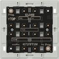
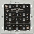
ETS product family: Push-button
Product type: 2-gang push-button
2 red LEDs: actuator status
KNX RF radio transmitter module 3-gang for cover kit 3-gang, ref.-no.: .. 403 TSA .. for cover 2-gang with symbols, ref.-no.: .. 402 TSAP .. for cover 4-gang with symbols, ref.-no.: .. 404 TSAP ..
ETS product family: Push-button
Product type: 3-gang push-button
3 red LEDs: actuator status
4071 RF TSM
4072 RF TSM
4073 RF TSM
KNX RF radio transmitter modules F 40 including mounting plate, adhesive pad and fastening screw Adapter frames are included in delivery: ref.-no. LS 4 AR for LS range (pre-mounted) and ref.-no. CD 4 AR for CD range. AS / A ranges without adapter frame. 83
1 blue LED: transmission status
1 blue LED: transmission status
1 blue LED: transmission status
KNX RF Radio hand-held transmitters
Ref.-no.
KNX RF radio transmitter module 4-gang for cover kit 4-gang, ref.-no.: .. 404 TSA .. for cover 4-gang with symbols, ref.-no.: .. 404 TSAP .. ETS product family: Push-button Product type: 4-gang push-button

4 red LEDs: actuator status
1 blue LED: transmission status
Cover kits see as of page 66
KNX RF radio hand-held transmitter
Project design and commissioning with ETS5 or a more recent version.
Intended use
• Radio operation of loads, e.g. light on/off, dimming, Venetian blinds up/down, brightness values, calling up and saving light scenes
• Operation in cabled KNX systems via radio converter (ref.-no.: MK 100 RF)
Product characteristics
• Push-button functions switching, dimming, blind control, value transmitter, scene recall, etc.
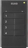
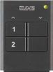
• Button pairs for push-button function or rocker function
• Two-colour LED to display actuation, sending status and actuator feedback
• Battery-powered device
2-gang
4-gang
84
4074 RF TSM
KNX RF radio hand-held transmitter
HS 2 RF
KNX RF radio hand-held transmitter
HS 4 RF
KNX RF Accessories
KNX RF radio USB stick
Intended use
• PC interface for the addressing, programming and diagnostics of KNX RF devices
• USB stick for coupling to a PC with a Windows-based operating system
Product characteristics
• Commissioning, programming, visualisation and diagnostics of KNX RF devices
• Automatic installation of PC communication via HID profile
Technical data
Rated voltage: DC 5 V
USB version: 2.0
Connection USB: type A
Ambient temperature: −10 ... +70 °C
Relative humidity: max. 80 % (no condensation)
Radio frequency: 868.0 ... 868.6 MHz
Transmitting power: max. 20 mW
Transmission range in free field: typical 100 m
KNX RF radio converter
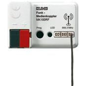
Project design and commissioning with ETS5 or a more recent version.
Intended use
• KNX medium: TP 256
• KNX Data Secure compatible with ETS 5.7.3 or higher
• Connection of KNX radio networks with cabled KNX lines
• Extension of the radio range in KNX radio networks (repeater operation, external power supply with 24 V AC/DC, e.g. ref.-no. NT 2415 REG VDC)
• Installation in flush box according to DIN 49073 in combination with a suitable cover
85
Ref.-no.
USB 2130 RF
MK 100 RF
KNX push-button sensor F 10
A FLOW in matt anthracite
The F 10 family
The JUNG KNX push-button F 10 looks like a classic light switch, but masters intelligent KNX technology. Thanks to the JUNG design, it perfectly complements the widest range of furnishing styles. Thus the technology and design form a unit that meets the toughest demands.
KNX PUSH-BUTTON F 10 STANDARD
The KNX F 10 push-button sensor operates consumers, dims lights, moves blinds and much more. All KNX functions are possible with its operating concept (rocker or push-button). Up to two functions can be set per operating button.
KNX PUSH-BUTTON F 10 UNIVERSAL
The Universal design has in addition a locking and alarm function, a temperature sensor and offers the option to connect a KNX push-button extension. Installation push-buttons or reed contacts can also be connected to the KNX F 10 push-button sensor.
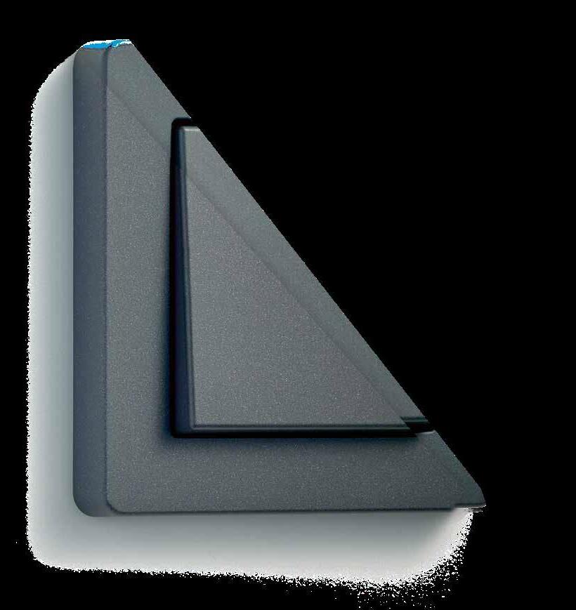
KNX PUSH-BUTTON EXTENSION
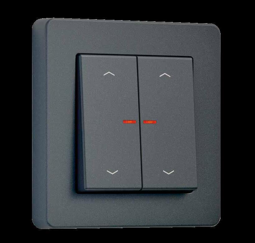

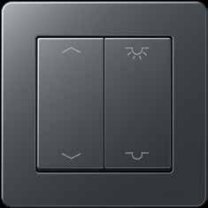

Cost-efficient KNX installation: the KNX F 10 push-button sensor Universal version can be connected to a KNX push-button extension via the appropriate connections.
JUNG KNX SECURE
All versions of the JUNG KNX F 10 push-button sensor are secure thanks to KNX Data Secure. The encryption secures and authenticates all data in the KNX system.
PUSH-BUTTON SENSORS/ROOM CONTROLLERS 87 86 PUSH-BUTTON SENSORS/ROOM CONTROLLERS
Intelligent technology in a timeless design
KNX PUSH-BUTTON SENSOR F 10
KNX PUSH-BUTTON SENSOR F 10
Individual button assignment

KNX PUSH-BUTTON SENSOR F 10 KNX PUSH-BUTTON SENSOR F 10
LS 990 in aluminium
KNX PUSH-BUTTON SENSOR F 10
A 550 in white
KNX PUSH-BUTTON SENSOR F 10
Push-button function

Rocker function
KNX PUSH-BUTTON SENSOR F 10 KNX PUSH-BUTTON SENSOR F 10
CD 500 in white
A FLOW in aluminium
The JUNG KNX push-button F 10 is available with covers and devices of the A, AS, CD and LS ranges.
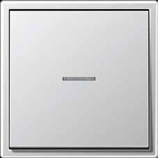
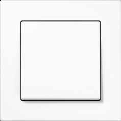
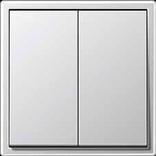

Push-button function 2-gang
Rocker function 2-gang
The KNX F 10 push-button masters both the push-button function and the rocker function. The rocker function of the Standard version enables additional control possibilities such
as dimming lamps. The push-button function in the Universal version enables full-surface operation.
PUSH-BUTTON SENSORS/ROOM CONTROLLERS 89 88 PUSH-BUTTON SENSORS/ROOM CONTROLLERS
The functions of the F 10
COVER IN LS 990 KNX PUSH-BUTTON F 10 INSERT
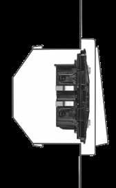
The new JUNG KNX push-buttons F 10 enable extensive options in the technical interior equipment of an intelligent building. They have large functional versatility.
INTUITIVE AND VERSATILE OPERATION
The function assignment of the JUNG KNX F 10 push-button sensor can be completely customised. The push-buttons in the Universal version switch blinds, dim lights or operate other functions in a smart building. In addition, their individual switching points can be assigned multiple times thanks to a sophisticated operating concept. In this way, they make particularly versatile control of the intelligent building possible.
TEMPERATURE SENSOR
The JUNG KNX F 10 push-button in the Universal version has a temperature sensor. It thus records the room temperature with pinpoint accuracy and passes the information on to, for example, a KNX temperature controller Fan Coil. This then regulates the heating to a desired value.
NUMEROUS ADDITIONAL FUNCTIONS
In the guise of a classic switch, the JUNG KNX push-buttons F 10 provide a wide range of functions. Both versions have a controller satellite unit and an energy saving mode. The KNX F 10 Universal push-button also has alarm signalling, lock function and HSV colour control.
SMALL INSTALLATION DEPTH
Due to the compact design of the KNX F 10 push-buttons, tradespeople have more room to work with. For example, the small installation depth of only 15 millimetres creates a lot more space for the wiring.
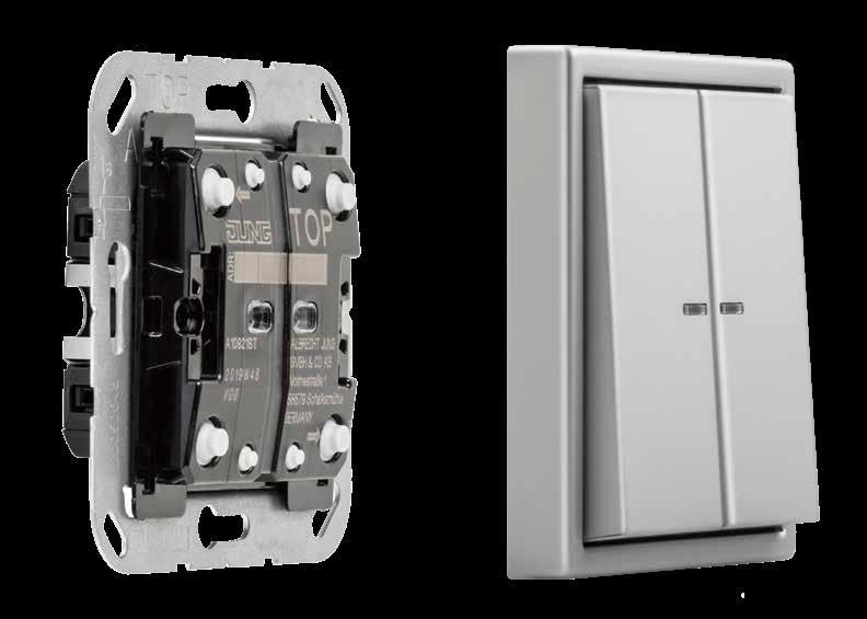
PUSH-BUTTON SENSORS/ROOM CONTROLLERS 91 90 PUSH-BUTTON SENSORS/ROOM CONTROLLERS
System design for KNX push-button sensor Standard and Universal


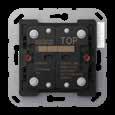
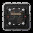
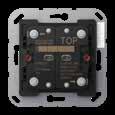
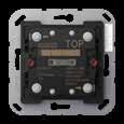
System design for KNX push-button extension


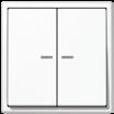
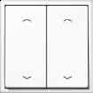
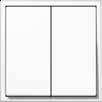


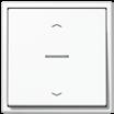


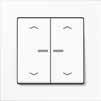
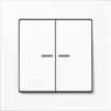
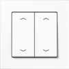
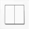
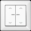
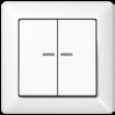
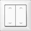

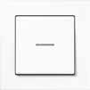
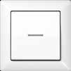

AS range AS range AS range AS range A range A range A range A range
1-gang Part No.: A 10911 TE
only be combined with Universal push-button sensors
2-gang Part No.: A 10921 TE Can only be combined with Universal push-button sensors CD range CD range CD range CD range LS range LS range LS range LS range Universal 1-gang Part No.: A 10911 ST Universal 2-gang Ref. no.: A 10921 ST
2-gang Part. no.: LS CD 10921 TE
Extension
Can
Extension
Extension
push-button sensors Universal 2-gang Ref. no.: LS CD 10921 ST
1-gang Ref. no.: LS CD 10911 TE
Can only be combined with Universal
Extension
Universal 1-gang Ref. no.: LS CD 10911 ST Standard 1-gang Part No.: A 10711 ST Standard 2-gang Ref. no.: A 10721 ST Standard 2-gang Ref. no.: LS CD 10721 ST Standard 1-gang Ref. no.: LS CD 10711 ST PUSH-BUTTON SENSORS/ROOM CONTROLLERS 93 92 PUSH-BUTTON SENSORS/ROOM CONTROLLERS
Can only be combined with Universal push-button sensors
Connection of an extension
Cost-efficient KNX installation: The KNX F 10 push-button sensor
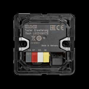
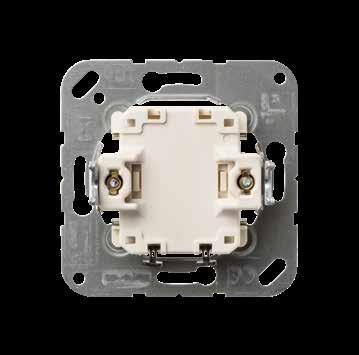
Universal can be connected to a KNX push-button extension, reed contacts or conventional push-buttons.
CONNECTION OF A PUSH-BUTTON
An extension connected to a KNX F 10 pushbutton sensor Universal can be placed at a distance of up to 30 metre cable length in the process. Thus the JUNG KNX push-buttons F 10 enable a smart and at the same time
considerably more cost-efficient electrical installation. The KNX F 10 push-button sensor provides a particularly versatile control of the complete smart building.
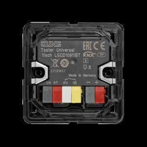
KNX 30 m 30 m KNX
ATTACHING A KNX PUSH-BUTTON EXTENSION
94 PUSH-BUTTON SENSORS/ROOM CONTROLLERS
KNX push-button
Intended use
• Operation of loads, e.g. light on/off, dimming, blinds up/down, brightness values, temperatures, calling up and saving light scenes, etc.
• Installation in flush box according to DIN 49073
Standard
Product characteristics
• KNX medium: TP 256
• Operating concept (rocker or button) adjustable for each operating area
• Button evaluation (single- or dual-area operation) adjustable
• One or two functions per operating area
• Integrated bus coupling unit
• One status LED per operating area – red
• KNX Data Secure compatible with ETS 5.7.3 or higher
Universal Product characteristics
• KNX medium: TP 256
• Operating concept (rocker or button) adjustable for each operating area
• Button evaluation (single- or dual-area operation) adjustable
• One or two functions per operating area
• Integrated bus coupling unit
• Alarm function, optional acknowledge by pressing any button
• Disabling function: Disabling or change function mode of single or all button functions
• Status LED brightness adjustable
• Measurement of room temperature
• Connection of a push-button extension possible
• Connection of installation buttons or reed contacts possible
• KNX Data Secure compatible with ETS 5.7.3 or higher
Extension
Product characteristics
• Operating concept (rocker or button) adjustable for each operating area
• Button evaluation (single- or dual-area operation) adjustable
• One or two functions per operating area
• Without status LED
• Without bus coupling unit
• Connection to push-button universal possible
95 KNX KNX push-buttons
10
F
KNX AS range KNX push-buttons F 10
Ref.-no.
KNX push-button standard 1-gang
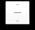

Project design and commissioning with ETS5 or a more recent version.
ETS product family: Push-button
Product type: 1-gang push-button
N A 10711 ST
KNX push-button universal 1-gang
Project design and commissioning with ETS5 or a more recent version.
ETS product family: Push-button
Product type: 1-gang push-button
N A 10911 ST
KNX push-button extension 1-gang N A 10911 TE
1-gang rocker for KNX push-button 1-gang ref.-no.: A 10711 ST, A 10911 ST, A 10911 TE
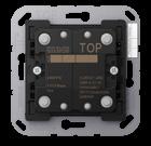
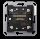
Duroplastic (scratch-proof) glossy
1-gang rocker with arrow symbols for KNX push-button 1-gang ref.-no.: A 10711 ST, A 10911 ST, A 10911 TE
Duroplastic (scratch-proof) glossy ivory
AS 101 P
AS 101 P WW
1-gang rocker with lens for KNX push-button 1-gang ref.-no.: A 10711 ST, A 10911 ST
Duroplastic (scratch-proof) glossy
ivory N AS 101 KO5 white N AS 101 KO5 WW
1-gang rocker with lens and arrow symbols for KNX push-button 1-gang ref.-no.: A 10711 ST, A 10911 ST
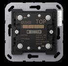
Duroplastic (scratch-proof) glossy ivory
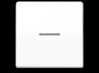

N AS 101 KO5P
white N AS 101 KO5P WW
96
N
white N
ivory
AS 101
AS 101 WW
N
white N
KNX push-button standard 2-gang
Project design and commissioning with ETS5 or a more recent version.
ETS product family: Push-button
Product type: 2-gang push-button
N A 10721 ST
KNX push-button universal 2-gang
Project design and commissioning with ETS5 or a more recent version.
ETS product family: Push-button
Product type: 2-gang push-button
N A 10921 ST
KNX push-button extension 2-gang N A 10921 TE
2-gang rocker for KNX push-button 2-gang ref.-no.: A 10721 ST, A 10921 ST, A 10921 TE
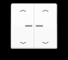
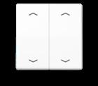

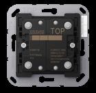
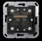
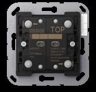
Duroplastic (scratch-proof) glossy ivory N AS 102
2-gang rocker with arrow symbols for KNX push-button 2-gang ref.-no.: A 10721 ST, A 10921 ST, A 10921 TE
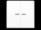
Duroplastic (scratch-proof) glossy ivory N AS 102 P
AS 102 P WW
2-gang rocker with lens for KNX push-button 2-gang ref.-no.: A 10721 ST, A 10921 ST
Duroplastic (scratch-proof) glossy
ivory
N AS 102 KO5 white N AS 102 KO5 WW
2-gang rocker with lens and arrow symbols for KNX push-button 2-gang ref.-no.: A 10721 ST, A 10921 ST
Duroplastic (scratch-proof) glossy
ivory
N AS 102 KO5P
white N AS 102 KO5P WW
Ref.-no. 97
KNX AS range KNX push-buttons F 10
white N AS 102 WW
white N
KNX A range KNX push-buttons F 10
KNX push-button standard 1-gang
Project design and commissioning with ETS5 or a more recent version.
ETS product family: Push-button
Product type: 1-gang push-button
KNX push-button universal 1-gang
Project design and commissioning with ETS5 or a more recent version.
ETS product family: Push-button
Product type: 1-gang push-button
KNX push-button extension 1-gang
1-gang rocker for KNX push-button 1-gang ref.-no.: A 10711 ST, A 10911 ST, A 10911 TE


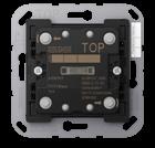
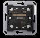
Duroplastic (scratch-proof) glossy
lacquered
(breakproof) high-gloss
1-gang rocker with arrow symbols for KNX push-button 1-gang ref.-no.: A 10711 ST, A 10911 ST, A 10911 TE
Duroplastic (scratch-proof) glossy
lacquered
(breakproof) high-gloss
Ref.-no.
A 10711 ST
98
N
N A
ST
10911
N A
TE
10911
white N A 101 WW black N A 101 SW Duroplastic
aluminium N L A 101 AL champagne N A 101 CH mocha N A 101 MO Thermoplastic
white N L A 101 BF WW black N L A 101 BF SW matt lacquered matt snow white N A 101 BF WWM matt graphite black N A 101 BF SWM matt anthracite N A 101 BF ANM
white N A 101 P WW black N A 101 P SW Duroplastic
aluminium N A 101 P AL champagne N A 101 P CH mocha N A 101 P MO Thermoplastic
white N A 101 P BF WW black N A 101 P BF SW matt
matt anthracite N A 101 P BF ANM
lacquered
1-gang rocker with lens for KNX push-button 1-gang ref.-no.: A 10711 ST, A 10911 ST

Duroplastic (scratch-proof) glossy
Duroplastic
1-gang rocker with lens and arrow symbols for KNX push-button 1-gang ref.-no.: A 10711 ST, A 10911 ST
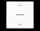
Duroplastic (scratch-proof) glossy
Thermoplastic (breakproof) high-gloss
Ref.-no. 99
KNX A range KNX push-buttons F 10
white N A 101 KO5 WW black N A 101 KO5 SW
lacquered aluminium N L A 101 KO5 AL champagne N A 101 KO5 CH mocha N A 101 KO5 MO
white N L A 101 KO5 BF WW black N L A 101 KO5 BF SW matt lacquered matt snow white N A 101 KO5 BF WWM matt graphite black N A 101 KO5 BF SWM matt anthracite N A 101 KO5 BF ANM
Thermoplastic (breakproof) high-gloss
white N A 101 KO5P WW black N A 101 KO5P SW Duroplastic lacquered aluminium N A 101 KO5P AL champagne N A 101 KO5P CH mocha N A 101 KO5P MO
white N A 101 KO5P BF WW black N A 101 KO5P BF SW matt lacquered matt anthracite N A 101 KO5P BF ANM
KNX A range KNX push-buttons F 10
KNX push-button standard 2-gang
Project design and commissioning with ETS5 or a more recent version.
ETS product family: Push-button
Product type: 2-gang push-button
KNX push-button universal 2-gang
Project design and commissioning with ETS5 or a more recent version.
ETS product family: Push-button
Product type: 2-gang push-button
KNX push-button extension 2-gang
2-gang rocker for KNX push-button 2-gang ref.-no.: A 10721 ST, A 10921 ST, A 10921 TE
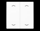

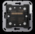
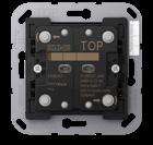
Duroplastic (scratch-proof) glossy
lacquered
(breakproof) high-gloss
2-gang rocker with arrow symbols for KNX push-button 2-gang ref.-no.: A 10721 ST, A 10921 ST, A 10921 TE
Duroplastic (scratch-proof) glossy
lacquered
(breakproof) high-gloss
Ref.-no.
A 10721 ST
100
N
N A
ST
10921
N A
10921 TE
white N A 102 WW black N A 102 SW Duroplastic
aluminium N L A 102 AL champagne N A 102 CH mocha N A 102 MO Thermoplastic
white N L A 102 BF WW black N L A 102 BF SW matt lacquered matt snow white N A 102 BF WWM matt graphite black N A 102 BF SWM matt anthracite N A 102 BF ANM
white N A 102 P WW black N A 102 P SW Duroplastic
aluminium N A 102 P AL champagne N A 102 P CH mocha N A 102 P MO Thermoplastic
white N A 102 P BF WW black N A 102 P BF SW matt
matt anthracite N A 102 P BF ANM
lacquered
2-gang rocker with lens for KNX push-button 2-gang ref.-no.: A 10721 ST, A 10921 ST
Duroplastic (scratch-proof) glossy
2-gang rocker with lens and arrow symbols for KNX push-button 2-gang ref.-no.: A 10721 ST, A 10921 ST
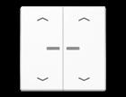
Duroplastic (scratch-proof) glossy
Thermoplastic (breakproof) high-gloss
Ref.-no. 101
KNX A range KNX push-buttons F 10
white N A 102 KO5 WW black N A 102 KO5 SW
lacquered aluminium N L A 102 KO5 AL champagne N A 102 KO5 CH mocha N A 102 KO5 MO
Duroplastic
white N L A 102 KO5 BF WW black N L A 102 KO5 BF SW matt lacquered matt snow white N A 102 KO5 BF WWM matt graphite black N A 102 KO5 BF SWM matt anthracite N A 102 KO5 BF ANM
Thermoplastic (breakproof) high-gloss
white N A 102 KO5P WW black N A 102 KO5P SW
lacquered aluminium N A 102 KO5P AL champagne N A 102 KO5P CH mocha N A 102 KO5P MO
white N A 102 KO5P BF WW black N A 102 KO5P BF SW matt lacquered matt anthracite N A 102 KO5P BF ANM
Duroplastic
KNX CD range KNX push-buttons F 10
Ref.-no.
KNX push-button standard 1-gang


Project design and commissioning with ETS5 or a more recent version.
ETS product family: Push-button
Product type: 1-gang push-button
N LS CD 10711 ST
KNX push-button universal 1-gang
Project design and commissioning with ETS5 or a more recent version.
ETS product family: Push-button
Product type: 1-gang push-button
N LS CD 10911 ST
KNX push-button extension 1-gang
N LS CD 10911 TE
1-gang rocker for KNX push-button 1-gang ref.-no.: LS CD 10711 ST, LS CD 10911 ST, LS CD 10911 TE
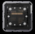
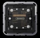
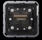
Duroplastic (scratch-proof) glossy
CD 101 white
ivory
CD 101 WW brown
CD 101 GR
CD 101 BR grey
light grey
metal versions (anodized aluminium)
gold-bronze
platinum
CD 101 SW
CD 101 LG black
L CD 101 GB
L CD 101 PT
1-gang rocker with arrow symbols for KNX push-button 1-gang ref.-no.: LS CD 10711 ST, LS CD 10911 ST, LS CD 10911 TE
Duroplastic (scratch-proof) glossy
ivory N CD 101 P
white N CD 101 P WW
brown
grey
light grey
black
metal versions (anodized aluminium)
CD 101 P BR
CD 101 P GR
CD 101 P LG
CD 101 P SW
gold-bronze N CD 101 P GB
platinum N CD 101 P PT
102
N
N
N
N
N
N
N
N
N
N
N
N
1-gang rocker with lens for KNX push-button 1-gang ref.-no.: LS CD 10711 ST, LS CD 10911 ST
Duroplastic (scratch-proof) glossy
ivory
white
brown
grey
light grey
black
metal versions (anodized aluminium)
gold-bronze
platinum
Ref.-no.
N CD 101 KO5
N CD 101 KO5 WW
N CD 101 KO5 BR
N CD 101 KO5 GR
N CD 101 KO5 LG
N CD 101 KO5 SW
N L CD 101 KO5 GB
N L CD 101 KO5 PT
1-gang rocker with lens and arrow symbols for KNX push-button 1-gang ref.-no.: LS CD 10711 ST, LS CD 10911 ST
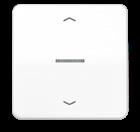

Duroplastic (scratch-proof) glossy
ivory
white
brown
grey
light grey
black
metal versions (anodized aluminium)
gold-bronze
platinum
N CD 101 KO5P
N CD 101 KO5P WW
N CD 101 KO5P BR
N CD 101 KO5P GR
N CD 101 KO5P LG
N CD 101 KO5P SW
N CD 101 KO5P GB
N CD 101 KO5P PT
103
KNX CD range KNX push-buttons F 10
KNX CD range KNX push-buttons F 10
Ref.-no.
KNX push-button standard 2-gang


Project design and commissioning with ETS5 or a more recent version.
ETS product family: Push-button
Product type: 2-gang push-button
N LS CD 10721 ST
KNX push-button universal 2-gang Project design and commissioning with ETS5 or a more recent version.
ETS product family: Push-button
Product type: 2-gang push-button N LS CD 10921 ST
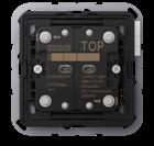
KNX push-button extension 2-gang N LS CD 10921 TE
2-gang rocker for KNX push-button 2-gang ref.-no.: LS CD 10721 ST, LS CD 10921 ST, LS CD 10921 TE
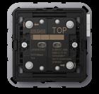
Duroplastic (scratch-proof) glossy
2-gang rocker with arrow symbols for KNX push-button 2-gang ref.-no.: LS CD 10721 ST, LS CD 10921 ST, LS CD 10921 TE
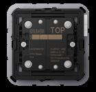
Duroplastic (scratch-proof) glossy
CD 102 P
CD 102 P WW
CD 102 P GR light grey
Duroplastic lacquered gold-bronze
102 P LG
CD 102 P SW
CD 102 P GB
CD 102 P PT
104
ivory N
white N
brown N CD
grey N CD
light
N CD
black N CD
N CD
platinum N CD
CD 102
CD 102 WW
102 BR
102 GR
grey
102 LG
102 SW Duroplastic lacquered gold-bronze
102 GB
102 PT
ivory N
white N
brown N
N
N
black N
CD 102 P BR grey
CD
N
platinum N
2-gang rocker with lens for KNX push-button 2-gang ref.-no.: LS CD 10721 ST, LS CD 10921 ST
Duroplastic (scratch-proof) glossy
ivory
white
brown
grey
light grey
black
Duroplastic lacquered
gold-bronze
platinum
Ref.-no.
N CD 102 KO5
N CD 102 KO5 WW
N CD 102 KO5 BR
N CD 102 KO5 GR
N CD 102 KO5 LG
N CD 102 KO5 SW
N CD 102 KO5 GB
N CD 102 KO5 PT
2-gang rocker with lens and arrow symbols for KNX push-button 2-gang ref.-no.: LS CD 10721 ST, LS CD 10921 ST

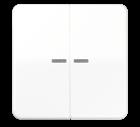
Duroplastic (scratch-proof) glossy
ivory
white
brown
grey
light grey
black
Duroplastic lacquered
gold-bronze
platinum
N CD 102 KO5P
N CD 102 KO5P WW
N CD 102 KO5P BR
N CD 102 KO5P GR
N CD 102 KO5P LG
N CD 102 KO5P SW
N CD 102 KO5P GB
N CD 102 KO5P PT
105
KNX CD range KNX push-buttons F 10
KNX LS range KNX push-buttons F 10
Ref.-no.
KNX push-button standard 1-gang
Project design and commissioning with ETS5 or a more recent version.
ETS product family: Push-button
Product type: 1-gang push-button N LS CD 10711 ST
KNX push-button universal 1-gang
Project design and commissioning with ETS5 or a more recent version.
ETS product family: Push-button
Product type: 1-gang push-button
KNX push-button extension 1-gang
CD 10911 ST
LS CD 10911 TE
1-gang rocker for KNX push-button 1-gang ref.-no.: LS CD 10711 ST, LS CD 10911 ST, LS CD 10911 TE


106
N
LS
N
ivory N LS 101 white N LS 101 WW light grey N LS 101 LG black N LS 101 SW matt lacquered matt snow white N LS 101 WWM matt graphite black N LS 101 SWM metal versions aluminium N P L AL 101 stainless steel N L ES 101 anthracite (aluminium lacquered) N AL 101 AN dark (aluminium lacquered) N AL 101 D chrome N GCR 101 gold-coloured N GO 101 classic brass N P ME 101 C antique brass N ME 101 AT
Duroplastic (scratch-proof) glossy
KNX push-buttons F 10
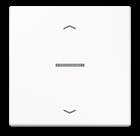
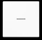
1-gang rocker with arrow symbols for KNX push-button 1-gang ref.-no.: LS CD 10711 ST, LS CD 10911 ST, LS CD 10911 TE Duroplastic (scratch-proof) glossy

1-gang rocker with lens for KNX push-button 1-gang ref.-no.: LS CD 10711 ST, LS CD 10911 ST
glossy
1-gang rocker with lens and arrow symbols for KNX push-button 1-gang ref.-no.: LS CD 10711 ST, LS CD 10911 ST
Duroplastic (scratch-proof) glossy
Ref.-no. 107
KNX LS range
ivory N LS 101 P white N LS 101 P WW light grey N LS 101 P LG black N LS 101 P SW metal versions aluminium N AL 101 P stainless steel N ES 101 P anthracite (aluminium lacquered) N AL 101 P AN dark (aluminium lacquered) N AL 101 P D chrome N GCR 101 P gold-coloured N GO 101 P classic brass N ME 101 P C antique brass N ME 101 P AT
Duroplastic
ivory N LS 101 KO5 white N LS 101 KO5 WW light grey N LS 101 KO5 LG black N LS 101 KO5 SW matt lacquered matt snow white N LS 101 KO5 WWM matt graphite black N LS 101 KO5 SWM metal versions aluminium N P L AL 101 KO5 stainless steel N L ES 101 KO5 anthracite (aluminium lacquered) N AL 101 KO5 AN dark (aluminium lacquered) N AL 101 KO5 D chrome N GCR
gold-coloured N GO
classic brass N P ME
C antique
N
(scratch-proof)
101 KO5
101 KO5
101 KO5
brass
ME 101 KO5 AT
ivory N
white N
light
N
black N
metal
aluminium N
stainless
N
N
dark
N
chrome N
N
classic
N
C antique
N
LS 101 KO5P
LS 101 KO5P WW
grey
LS 101 KO5P LG
LS 101 KO5P SW
versions
AL 101 KO5P
steel
ES 101 KO5P anthracite (aluminium lacquered)
AL 101 KO5P AN
(aluminium lacquered)
AL 101 KO5P D
GCR 101 KO5P gold-coloured
GO 101 KO5P
brass
ME 101 KO5P
brass
ME 101 KO5P AT
KNX LS range KNX push-buttons F 10
Ref.-no.
KNX push-button standard 2-gang Project design and commissioning with ETS5 or a more recent version.
ETS product family: Push-button
Product type: 2-gang push-button
KNX push-button universal 2-gang Project design and commissioning with ETS5 or a more recent version.
ETS product family: Push-button
Product type: 2-gang push-button
LS CD 10721 ST
KNX push-button extension 2-gang
CD 10921 ST
CD 10921 TE
2-gang rocker for KNX push-button 2-gang ref.-no.: LS CD 10721 ST, LS CD 10921 ST, LS CD 10921 TE

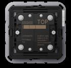
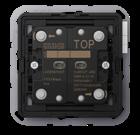
108
N
N LS
N
LS
ivory N LS 102 white N LS 102 WW light grey N LS 102 LG black N LS 102 SW matt lacquered matt snow white N LS 102 WWM matt graphite black N LS 102 SWM metal versions aluminium N P L AL 102 stainless steel N L ES 102 anthracite (aluminium lacquered) N AL 102 AN dark (aluminium lacquered) N AL 102 D chrome N GCR 102 gold-coloured N GO 102 classic brass N P ME 102 C antique brass N ME 102 AT
Duroplastic (scratch-proof) glossy
2-gang rocker with arrow symbols for KNX push-button 2-gang ref.-no.: LS CD 10721 ST, LS CD 10921 ST, LS CD 10921 TE Duroplastic (scratch-proof) glossy
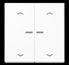
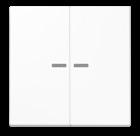
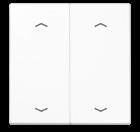
2-gang rocker with lens for KNX push-button 2-gang ref.-no.: LS CD 10721 ST, LS CD 10921 ST
glossy
2-gang rocker with lens and arrow symbols for
push-button 2-gang ref.-no.: LS CD 10721 ST, LS CD 10921 ST Duroplastic (scratch-proof) glossy
Ref.-no. 109
KNX LS range KNX push-buttons F 10
ivory N LS 102 P white N LS 102 P WW light grey N LS 102 P LG black N LS 102 P SW metal versions aluminium N AL 102 P stainless steel N ES 102 P anthracite (aluminium lacquered) N AL 102 P AN dark (aluminium lacquered) N AL 102 P D chrome N GCR 102 P gold-coloured N GO 102 P classic brass N ME 102 P C antique brass N ME 102 P AT
Duroplastic
ivory N LS 102 KO5 white N LS 102 KO5 WW light grey N LS 102 KO5 LG black N LS 102 KO5 SW matt lacquered matt snow white N LS 102 KO5 WWM matt graphite black N LS 102 KO5 SWM metal versions aluminium N P L AL 102 KO5 stainless steel N L ES 102 KO5 anthracite (aluminium lacquered) N AL 102 KO5 AN dark (aluminium lacquered) N AL 102 KO5 D chrome N GCR 102 KO5 gold-coloured N GO 102 KO5 classic brass N P ME 102 KO5 C antique brass N ME 102 KO5 AT
(scratch-proof)
ivory N LS 102 KO5P white N LS 102 KO5P WW light grey N LS 102 KO5P LG black N LS 102 KO5P SW metal versions aluminium N AL 102 KO5P stainless steel N ES 102 KO5P anthracite (aluminium lacquered) N AL
KO5P AN dark (aluminium lacquered) N AL
KO5P D chrome N GCR
KO5P gold-coloured N GO
KO5P classic brass N ME 102 KO5P C antique brass N ME 102 KO5P AT
KNX
102
102
102
102
KNX surface-mounted push buttons
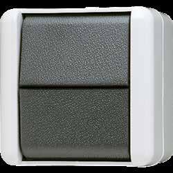
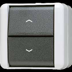
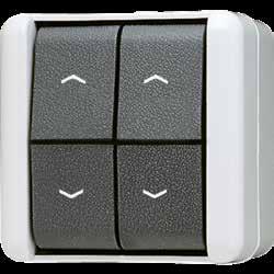

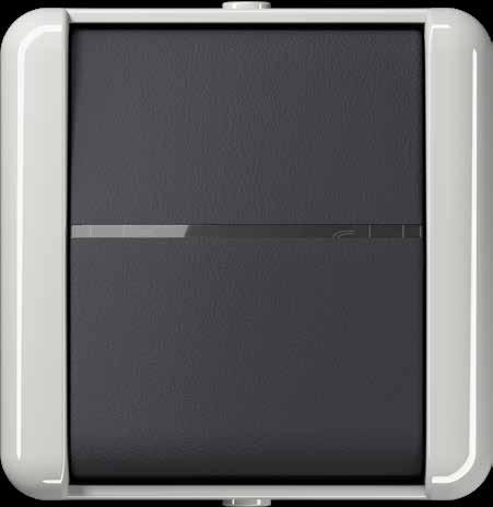
The KNX surface-mounted push buttons in unbreakable thermoplastic are weatherproof and UV-resistant to the greatest possible extent. The splash-water protected WG 800 range can be labelled throughout the range and has ample space for professional electrical installation. It is used everywhere that a surface-mounted installation is necessary.
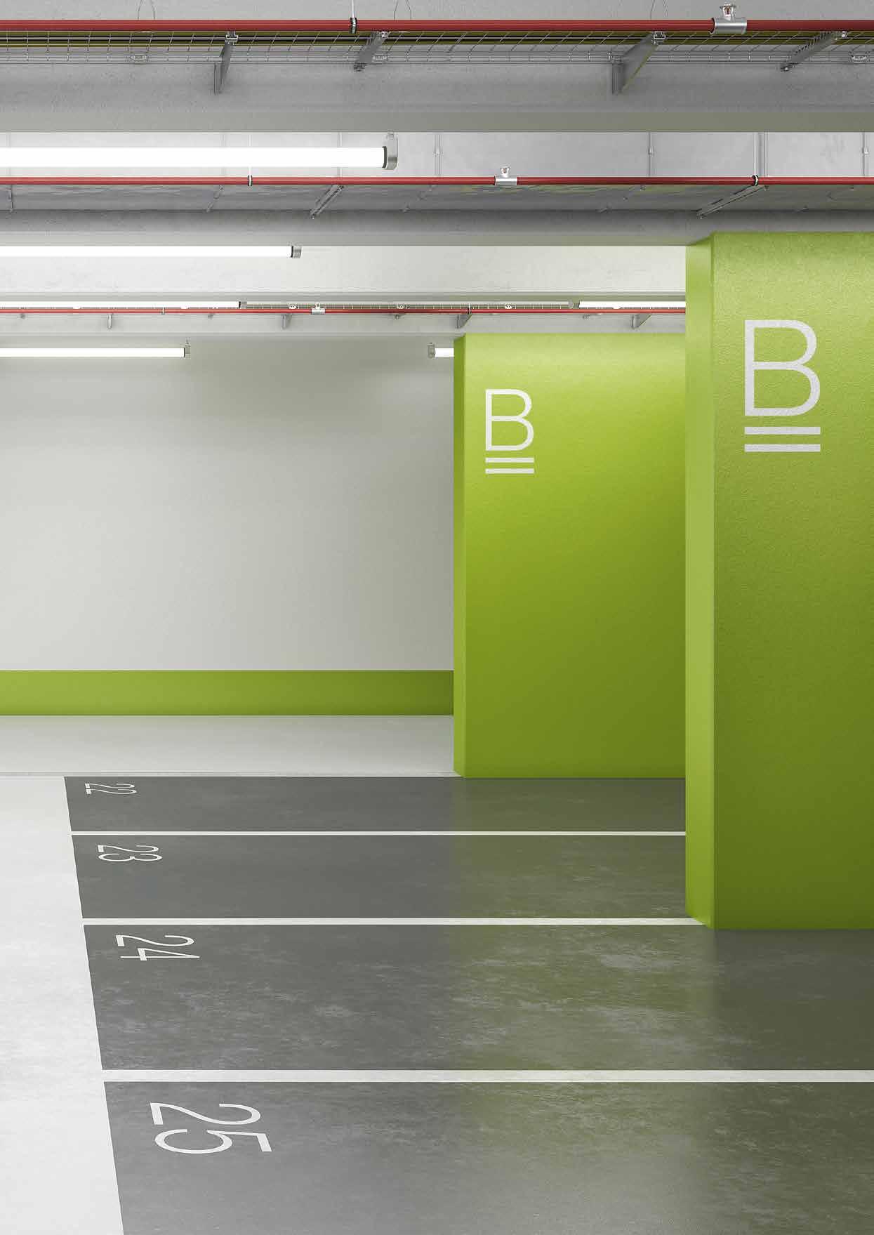 KNX PUSH-BUTTON 1-GANG KNX PUSH-BUTTON 1-GANG
KNX PUSH-BUTTON 2-GANG KNX PUSH-BUTTON 2-GANG
Rocker with push-button function above and below
Rocker with push-button function above and below
Rocker with push-button function only below
KNX PUSH-BUTTON 1-GANG KNX PUSH-BUTTON 1-GANG
KNX PUSH-BUTTON 2-GANG KNX PUSH-BUTTON 2-GANG
Rocker with push-button function above and below
Rocker with push-button function above and below
Rocker with push-button function only below
ROTARY SENSORS/PUSH-BUTTONS BCU 111 110 ROTARY SENSORS / PUSH-BUTTONS BCU
Rocker with push-button function above and below
Ref.-no.
Depending on the version of the push-button BCU – 1-gang rocker or 2-gang rocker – centre plates are used with and without indication lights.
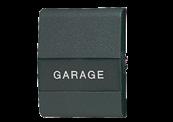
The “upper” or “lower” rockers can be controlled with the push-button with “neutral position”, while only the “lower” rocker can be pressed with the push-button with “switch position”. The push-button BCU can only function with an application program i.e. the push-button BCU consists of the device (hardware) and the application program (software).
KNX push-button BCU, neutral position
Function: switching, dimming, shutter control
LED: always ON, always OFF, status indication
KNX medium: TP 256
The status LED serves as an orientation light or status indicator and can be parameterised.
KNX push-button BCU, switch position
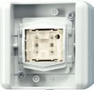
Function: switching, dimming LED: always ON, always OFF
KNX medium: TP 256
The status LED serves as an orientation light or status indicator and can be parameterised.
1-gang rocker with lens for 1-gang push-button BCU neutral position ref.-no.: 8471.02 LED W switch position ref.-no.: 8471.01 LED W
800 NT
LED W
1-gang rocker with lens and arrow symbols for 1-gang push-button BCU neutral position ref.-no.: 8471.02 LED W


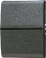
800 P
Rocker with inscription field for 1-gang push-button BCU neutral position ref.-no.: 8471.02 LED W switch position ref.-no.: 8471.01 LED W with inscription field 22 x 48 mm
1-gang rocker with big lens for 1-gang push-button BCU neutral position ref.-no.: 8471.02 LED W switch position ref.-no.: 8471.01 LED W with red insert (ref.-no.: 33 NR)
800 NA
800 KO
112
KNX WG 800
Push-button BCU
1-gang 8471.02
1-gang 8471.01
LED W
Insert with symbol, opaque for switches with indicator light and push-buttons in design range WG 800
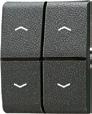
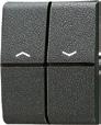


Push-button BCU
Insert without symbol, opaque for switches with indicator light and push-buttons in design range WG 800
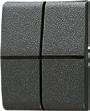
Insert without symbol, translucent for switches with indicator light and push-buttons in design range WG 800
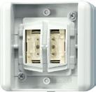
KNX push-button BCU, neutral position
Function: switching, dimming, shutter control
LED: always ON, always OFF, status indication
KNX medium: TP 256
The status LED serves as an orientation light or status indicator and can be parameterised.
KNX push-button BCU, switch position
Function: switching, dimming, shutter control
LED: always ON, always OFF
KNX medium: TP 256
The status LED serves as an orientation light or status indicator and can be parameterised.
2-gang rocker with lens for 2-gang push-button BCU
neutral position ref.-no.: 8472.02 LED W
switch position ref.-no.: 8472.01 LED W
2-gang rocker with lens and arrow symbols for 2-gang push-button BCU
switch position ref.-no.: 8472.01 LED W 805 P
2-gang rocker with lens and arrow symbols for 2-gang push-button BCU
neutral position ref.-no.: 8472.02 LED W 805 MP

Ref.-no. 113
KNX WG 800
anthracite symbol light 33 AN L symbol bell 33 AN K symbol door 33 AN T
anthracite 33 AN N
green 33 GN transparent 33 KLAR red 33 NR
2-gang 8472.02 LED W
2-gang 8472.01 LED W
NT
805
KNX rotary sensor
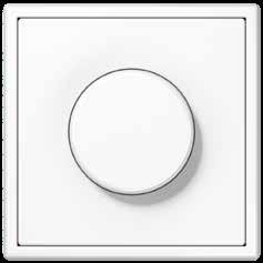


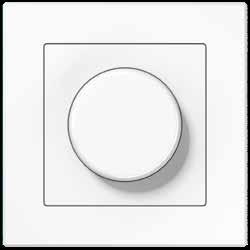
While the operation is the same as with a classic rotary dimmer, the functionality for the KNX rotary sensor is much more extensive. The room functions and scenes are controlled here according to the proven “turn and press” principle. It also harmonises perfectly with the rest of the components in the JUNG design.
 KNX rotary sensor
LS 990 in chrome
in white
in white
in white
in white
AS 500 A CREATION
CD 500
KNX rotary sensor
LS 990 in chrome
in white
in white
in white
in white
AS 500 A CREATION
CD 500
ROTARY SENSORS/PUSH-BUTTONS BCU 115 114 ROTARY SENSORS/PUSH-BUTTONS BCU
LS 990
Intuitive operating concept
FUNCTIONALITY
The KNX rotary sensor is used for controlling dimming, switching, and blind actuators as well as for the setpoint shift of a temperature controller. It has two red status LEDs for orientation.
Combination possibilities using satellites

One press of the push-button activates the programmed light scenario, that includes several lights in the living room, for example. All luminaires can be dimmed together using the KNX rotary sensor.
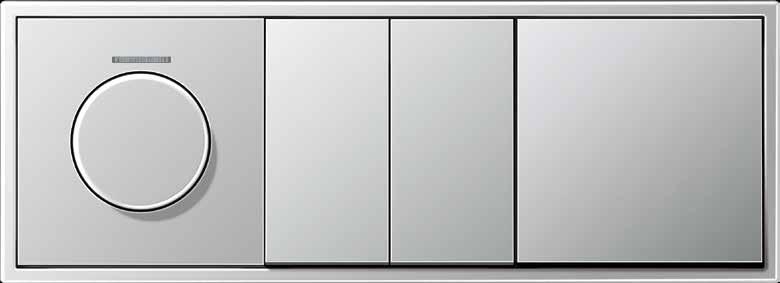
OPERATION
The innovation in the rotary sensor lies in the implementation of an operating concept that has never existed in the KNX system before. The well-known function of a rotary dimmer was used as the template. The rotary sensor operates according to the same principle and
also has three extension inputs to connect conventional, floating contacts of switches, buttons and magnetic contacts. These combination possibilities extend the range of functions many times over. Labelling using the Graphic Tool further optimises the handling.

All three binary inputs of the rotary sensor are used here: activate lighting scenes via the connected push-button, dim all connected luminaires together with the rotary sensor and also move the shutters up and down using the blind push-buttons.
The Hi-Fi system is switched on and the volume controlled with the rotary sensor. The floor lamp is controlled in parallel using the serial button. The push-button connected to the third extension input functions as energy-saving button: Pressing switches off the electricity for the connected consumers and they do not enter the energy-consuming standby mode.
Lighting control Blind control Temperature / climate control Music control
Light scene
Extension connections ROTARY SENSORS/PUSH-BUTTONS BCU 117 116 ROTARY SENSORS/PUSH-BUTTONS BCU
KNX line
KNX Rotary sensor
Ref.-no.
KNX rotary sensor with integrated BCU with integrated push-button interface 3-gang with push-button function and acoustic signal Function: switching, dimming, shutter control, value transmitter, scene extension
Intended use
• Operation of loads, e.g. light on/off, dimming, blinds up/down, brightness values, temperatures, calling up and saving light scenes, etc.
• Installation in flush box according to DIN 49073
Product characteristics
• KNX medium: TP 256
• Operation by turning or pressing the control button
• Integrated push-button interface: Three binary inputs for potential-free contacts
• Functions for control button and push-button interface: Switching, dimming, shutter control, value transmitters, calling up scenes, etc.
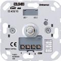
• Two red status LEDs
• Acoustic signal transmitter, e.g. for status, operation or alarm message, ringtone or audible alert
• Alarm function, optional with confirmation by pressing
• Convenience function for dimming and value adjustment: Preselection of the increment by fast turning
• Energy saving mode
• Separated locking functions for control button and push-button interface
118
DS 4092 TS
Centre plate with knob and lens for rotary sensor ref.-no.: DS 4092 TS


for AS and A ranges
Duroplastic (scratch-proof) glossy
ivory
white
Ref.-no.
P A 1540 KO5
P A 1540 KO5 WW
black A 1540 KO5 SW
Duroplastic lacquered
aluminium
champagne
P L A 1540 KO5 AL
P A 1540 KO5 CH
mocha A 1540 KO5 MO
Thermoplastic (breakproof) high-gloss
white
black
matt lacquered
matt anthracite
for CD range
Duroplastic (scratch-proof) glossy
ivory
white
grey
light grey
L A 1540 BF KO5 WW
L A 1540 BF KO5 SW
A 1540 BF KO5 ANM
P CD 1540 KO5
P CD 1540 KO5 WW
CD 1540 KO5 GR
P CD 1540 KO5 LG
black CD 1540 KO5 SW
for LS range
Duroplastic (scratch-proof) glossy
ivory
white
light grey
P LS 1940 KO5
P LS 1940 KO5 WW
P LS 1940 KO5 LG
black LS 1940 KO5 SW
metal versions
aluminium
stainless steel
anthracite (aluminium lacquered)
dark (aluminium lacquered)
P L AL 1940 KO5
L ES 1940 KO5
AL 1940 KO5 AN
AL 1940 KO5 D
chrome GCR 1940 KO5
gold-coloured
classic brass
antique brass
GO 1940 KO5
P ME 1940 KO5 C
ME 1940 KO5 AT
119
KNX Rotary sensor
KNX presence detector mini
Three mounting types.
FALSE CEILING
The most discrete installation type is clip-on mounting in a false ceiling. The spring clips ensure reliable fixing of the unit, and only the lens and the narrow design ring can be seen from below.

Unobtrusive, compact, precise: the KNX presence detector mini is all of these. It is designed to control lighting systems, room thermostats, and other electrical loads as needed. The striking feature is its compact design with three ceiling mounting options: Depending on the particular room situation, the unit may be installed in a false ceiling, on the surface, or in a commercial flush wall box.
FLUSH MOUNTING
Flush-mounted installation of the presence detector Mini or the brightness sensor is carried out by means of a separate flush mounting set in an off-the-shelf DIN 49073 flush wall box.
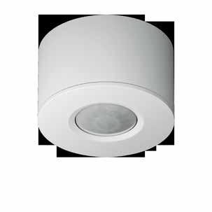
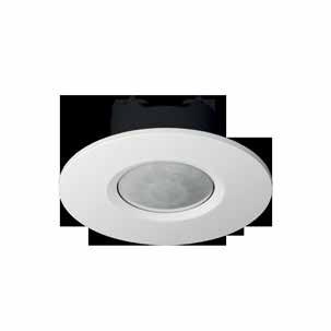
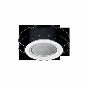
SURFACE MOUNTING
The third type of ceiling installation is the surface-mounted option. JUNG also provides a separate set for this that also includes a bezel as well as a surface cap for harmonious appearance.
Temperature measurement.
The ideal room temperature is highly dependent on individual feelings. With your feel-good temperature you create comfort for yourself. Moreover, flexible control of heating, ventilation, and cooling also provides healthy indoor climate. And also concerning energy-management aspects you can only win with heating and climate control matched to your needs!
KNX Presence Detector Mini is available in the Standard and Universal versions
RAUMAUTOMATION 121 120 RAUMAUTOMATION
Ref.-no.
KNX presence detector mini with integrated BCU
New in V 02: with temperature measurement (only "Universal" version)
ETS product family: Physical sensors
Product type: Movement
Intended use
• Requirement-oriented control of lighting, room thermostats and other electrical loads in interior rooms
• Clamp mounting in suspended ceilings
• Ceiling installation on fixed ceilings in appliance box according to DIN 49073 with flush mounting set (ref.-no.: PMM-UP-SET-WW)
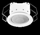
• Surface-mounted ceiling installation with surface mounting set (ref.-no.: PMM-AP-SET-WW)
Product characteristics
• Integrated bus coupling unit
• 3 PIR sensors
• Detection field 360°
• Integrated brightness sensor
• Deployed as presence detector, motion detector, or for alert operation
• Output functions: Switching, staircase function, switching with forced position, value transmitter, light scene extension, operating mode setting for room temperature controller
• Extension of the detection area by way of operating several devices as main unit or extension unit
• Adjuster for manual adjustment of sensitivity
• Status LED: Flashes during motion detection; depending on programming in normal operation or only during the walking test mode
Additional characteristics of "Universal" version:
• Manual operation with IR remote control possible (ref.-no.: KNX PM FB IR)
• 5 function blocks for motion detection each with 2 outputs
• Function blocks switchable, e.g. for day/night operation
• PIR sensors can be evaluated separately
• Brightness sensor function with 3 limiting values
• Light control with max. 3 channels, setpoint shift in operation, separate configuration of dimming-up, control and dimming-down phase
• Light control can be combined with presence detector function
• Temperature measurement
Presence detector function:
• Detection of the smallest motions e.g. at a workplace for detecting the presence of persons
• Switch on: Motion detection and brightness threshold not reached
• Switch off: No motion in the detection field and shut-off delay elapsed or brightness threshold exceeded
Motion detector function:
• Motion detection for passageways in buildings
• Switch on: Motion detection and brightness threshold not reached
• Switch off: No motion in the detection field and shut-off delay elapsed or brightness threshold exceeded After reacting and switching on, the motion detection works independently of the brightness.
Signalling mode:
• Brightness-independent detection of motions in the detection field
• Switch on: After detection of an adjustable number of motions within the set monitoring period
• Switch off: No motion in the detection field and shut-off delay elapsed
122
KNX Presence detector mini
Standard white IP 3361 M WW Universal white IP 3361-1 M WW
Presence detector mini
Technical data
KNX medium: TP 256
Rated voltage KNX: DC 21 ... 32 V SELV
Current consumption KNX: max. 10 mA
Connection bus: terminal
Protection class: III
Ambient temperature: −25 ... +55 °C
Storage/transport temperature: −25 ... +70 °C
Relative humidity: 10 ... 100 % (no condensation)
Protection level: IP 44
Ceiling cut-out (Ø x D): 44 x 35 mm
Dimensions (Ø x H): 53.5 x 38 mm (with design ring)
Max. thickness of the suspended ceiling: approx. 25 mm
Installation depth: min. 35 mm
Distance between concrete ceiling and suspended ceiling: min. 20 mm
Design ring Ø inside: 35.6 mm
Design ring Ø outside: 53.5 mm
Profile height design ring: 1.8 mm
Profile height lens: 5.5 mm
Motion detection
Detection angle: 360°
Range: Ø approx. 12 m (mounting height 3 m)
Brightness sensor
Measuring range: 10 ... 2,000 lx
Accuracy (≤ 80 lx): ± 10 lx
Accuracy (> 80 lx): ± 5 %
IR remote control for KNX presence detector mini universal ref.-no.: 3361-1 M .. for KNX universal automatic switch ref.-no.: .. 3181-1 .., .. 3281-1
Battery operation with one included lithium button cell (CR 2025)
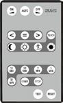
123
KNX
KNX PM FB IR
Ref.-no.
KNX Brightness controller mini
Ref.-no.
KNX brightness controller mini with integrated BCU
ETS product family: Physical sensors
Product type: Bightness
white IP 2096 LUX
Intended use
• Measurement and control of lighting indoors or in protected outdoor area
• Clamp mounting in suspended ceilings
• Ceiling installation on fixed ceilings in appliance box according to DIN 49073 with flush mounting set (ref.-no.: PMM-UP-SET-WW)
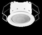
• Surface-mounted ceiling installation with surface mounting set (ref.-no.: PMM-AP-SET-WW)
Product characteristics
• Asymmetrical measuring surface
• Integrated bus coupling unit
• Integrated brightness sensor
• Brightness sensor function with 3 limiting values
• Brightness limiting values (3 channels) with output functions switching, value transmitter and scene extension
• Light control with max. 3 channels, setpoint shift in operation, separate configuration of dimming-up, control and dimming-down phase
• On-off control possible for switch actuators
• Power supply via bus voltage
Technical data
KNX medium: TP 256
Rated voltage KNX: DC 21 ... 32 V SELV
Current consumption KNX: max. 10 mA
Connection, KNX: terminal
Protection class: III
Ambient temperature: −25 ... +55 °C
Storage/transport temperature: −25 ... +70 °C
Relative humidity: 10 ... 100 % (no condensation)
Protection level: IP 44
Ceiling cut-out (Ø x D): 44 x 35 mm
Dimensions (Ø x H): 53.5 x 38 mm (with design ring)
Max. thickness of the suspended ceiling: approx. 25 mm
Installation depth: min. 35 mm
Distance between concrete ceiling and suspended ceiling: min. 20 mm
Design ring Ø inside: 35.6 mm
Design ring Ø outside: 53.5 mm
Profile height design ring: 1.8 mm
Profile height lens: 5.5 mm
Brightness measurement
Measuring range: 10 ... 2000 lx
Accuracy (> 80 lx): ± 5 %
Accuracy (≤ 80 lx): ± 10 lx
124
Ref.-no.
Flush mounting set for ceiling installation of KNX presence detector mini (ref.-no.: 3361 M WW, 3361-1 M WW) and KNX brightness controller mini (ref.-no.: 2096 LUX)
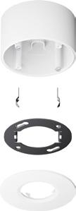
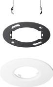
Installation in flush box according to DIN 49073
Design ring Ø inside: 35.6 mm, Ø outside: 80 mm
Profile height design ring: 3 mm
Profile height lens: 6.6 mm
white PMM-UP-SET-WW
Surface mounting set for ceiling installation of KNX presence detector mini (ref.-no.: 3361 M WW, 3361-1 M WW) and KNX brightness controller mini (ref.-no.: 2096 LUX)
Dimensions (Ø x H): 80 / 83 x 49 mm (incl. design ring)
Design ring Ø inside: 35.6 mm, Ø outside: 80 mm
white PMM-AP-SET-WW
125 KNX
Presence detector/
ceiling observer

DETECTION AREA
The KNX presence detector/ceiling observer has an especially homogeneous detection area of around 20 m (when installed at a height of 3 m). This allows precise motion detection even in large rooms.
This presence detector/ceiling observer is reliable. Even when great height is a problem. When installed at heights of up to 5 m, the unit registers everything that is moving within a diameter of approx. 20 m. The detection angle of 360° can be divided into three sensor segments of 120° each that can be enabled individually.

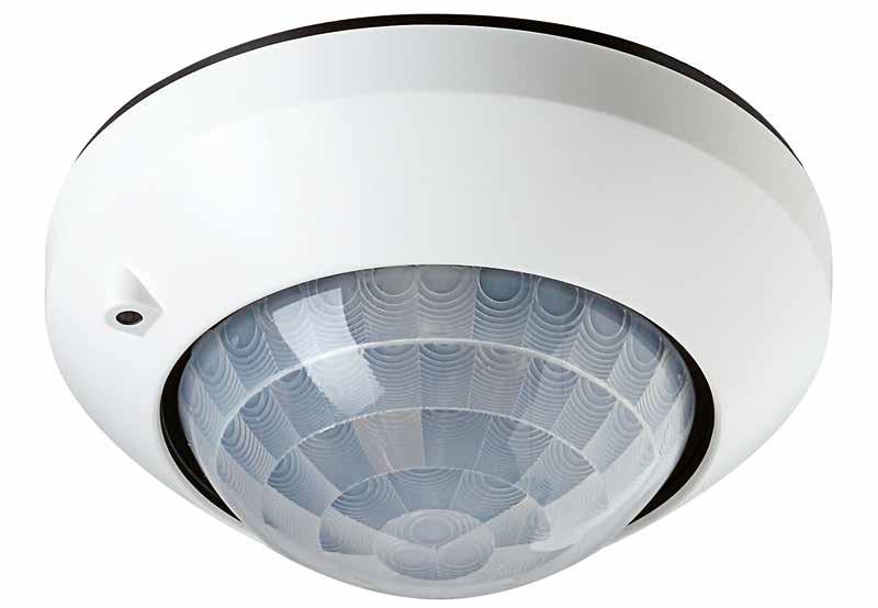


RANGE
The 360° detection angle can be divided into three separate 120° portions that can be activated individually and each allocated to one of the three PIR sensors.


These sensors can also be evaluated individually by software so that the “viewing direction” of the sensors can be modified using parameters (Universal version).
There are Standard and Universal versions of the presence detector/ceiling observer. In addition to presence-dependent constant light regulation, the Universal model also has five function blocks that operate independently of each other and to which the three PIR sensors can be assigned. Each functional block may be configured as desired for the presence detector, ceiling observer, or signalling applications.
For example, using KNX commands, the blocks can be switched to the respective required application, depending on the time of day and use. The unit may be optionally set up and operated using an IR remote control. Tip for installation in sports halls: the presence detector may optionally be fitted with a protective basket made of solid steel. Thus, it will be effectively protected against damage by thrown balls.
A B C
3 m Ø 20 m
PRESENCE DETECTOR/CEILING OBSERVER 127 126 PRESENCE DETECTOR/CEILING OBSERVER
There are Standard and Universal versions of the KNX presence detector/ceiling observer.
KNX Motion and presence detector
KNX presence detector with integrated BCU
ETS product family: Physical sensors
Product type: Movement
Ref.-no.
Intended use
• Requirement-oriented control of lighting, room thermostats and other electrical loads in interior rooms
• Ceiling mounting on fixed ceilings in appliance box according to DIN 49073 or surface-mounted housing ref.-no.: PM-KAPPE-1 or PM-KAPPE AL-1
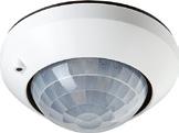
Product characteristics
• Integrated bus coupling unit
• 3 PIR sensors
• Detection field 360°
• Integrated brightness sensor
• Deployed as presence detector, motion detector, or for alert operation
• Output functions: Switching, staircase function, switching with forced position, value transmitter, light scene extension, operating mode setting for room temperature controller
• Extension of the detection area by way of operating several devices as main unit or extension unit
• Adjuster for manual adjustment of sensitivity
• Status LED: Flashes during motion detection; depending on programming in normal operation or only during the walking test mode
Additional characteristics of "Universal" version:
• Manual operation with IR remote control possible (ref.-no.: KNX PM FB IR)
• 5 function blocks for motion detection each with 2 outputs
• Function blocks switchable, e.g. for day/night operation
• PIR sensors can be evaluated separately
• Brightness sensor function with 3 limiting values
• Light control with max. 3 channels, setpoint shift in operation, separate configuration of dimming-up, control and dimming-down phase
• Light control can be combined with presence detector function
Presence detector function:
• Detection of the smallest motions e.g. at a workplace for detecting the presence of persons
• Switch on: Motion detection and brightness threshold not reached
• Switch off: No motion in the detection field and shut-off delay elapsed or brightness threshold exceeded
Motion detector function:
• Motion detection for passageways in buildings
• Switch on: Motion detection and brightness threshold not reached
• Switch off: No motion in the detection field and shut-off delay elapsed or brightness threshold exceeded After reacting and switching on, the motion detection works independently of the brightness.
Signalling mode:
• Brightness-independent detection of motions in the detection field
• Switch on: After detection of an adjustable number of motions within the set monitoring period
• Switch off: No motion in the detection field and shut-off delay elapsed
128
Standard white 3361
aluminium (lacquered) 3361
Universal white 3361-1
aluminium (lacquered) 3361-1
WW
AL
WW
AL
Motion and presence detector
KNX
Technical data
KNX medium: TP 256
Rated voltage KNX: DC 21 ... 32 V SELV
Current consumption KNX: max. 12.5 mA
Connection bus: terminal
Ambient temperature: −5 ... +45 °C
Storage/transport temperature: −25 ... +70 °C
Relative humidity: 5 ... 93 % (no condensation)
Protection class: III
Detection angle: 360°
Range: Ø approx. 20 m (mounting height 3 m)
Brightness sensor
Measuring range: 0 ... 2000 lx
Detection range: Ø 2 m
Surface-mounted housing for ceiling installation (surface-mounted) of KNX presence detectors ref. no.: 3361 WW, 3361 AL, 3361-1 WW, 3361-1 AL
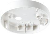
white PM-KAPPE-1
aluminium (lacquered) PM-KAPPE AL-1
Technical data
Dimensions (Ø x H): 103 x 19 mm
IR remote control for KNX presence detector universal ref.-no.: 3361-1 .. for KNX universal automatic switch ref.-no.: .. 3181-1 .., .. 3281-1
Battery operation with one included lithium button cell (CR 2025)
Protection cage for KNX presence detector ref.-no.: 3361..
varnished steel with plastic coating dimensions (Ø x H): approx. 180 x 90 mm
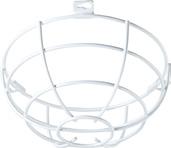
129
KNX PM FB IR
white SK 180-90 WW
Ref.-no.
KNX automatic switch
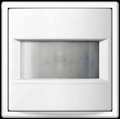
IMPROVED DETECTION CHARACTERISTICS, EXTENDED FUNCTIONALITY.
The 180-degree detection range is monitored by two PIR sensors that can be used individually or together. In this way, difficult room situations can also be optimally covered, such as small rooms or stairways. In this respect they are to be used as movement detectors in corridors and passages. On the other hand, as a “sentinel with switch-off brightness”, they are outstanding in use, for example, in offices.
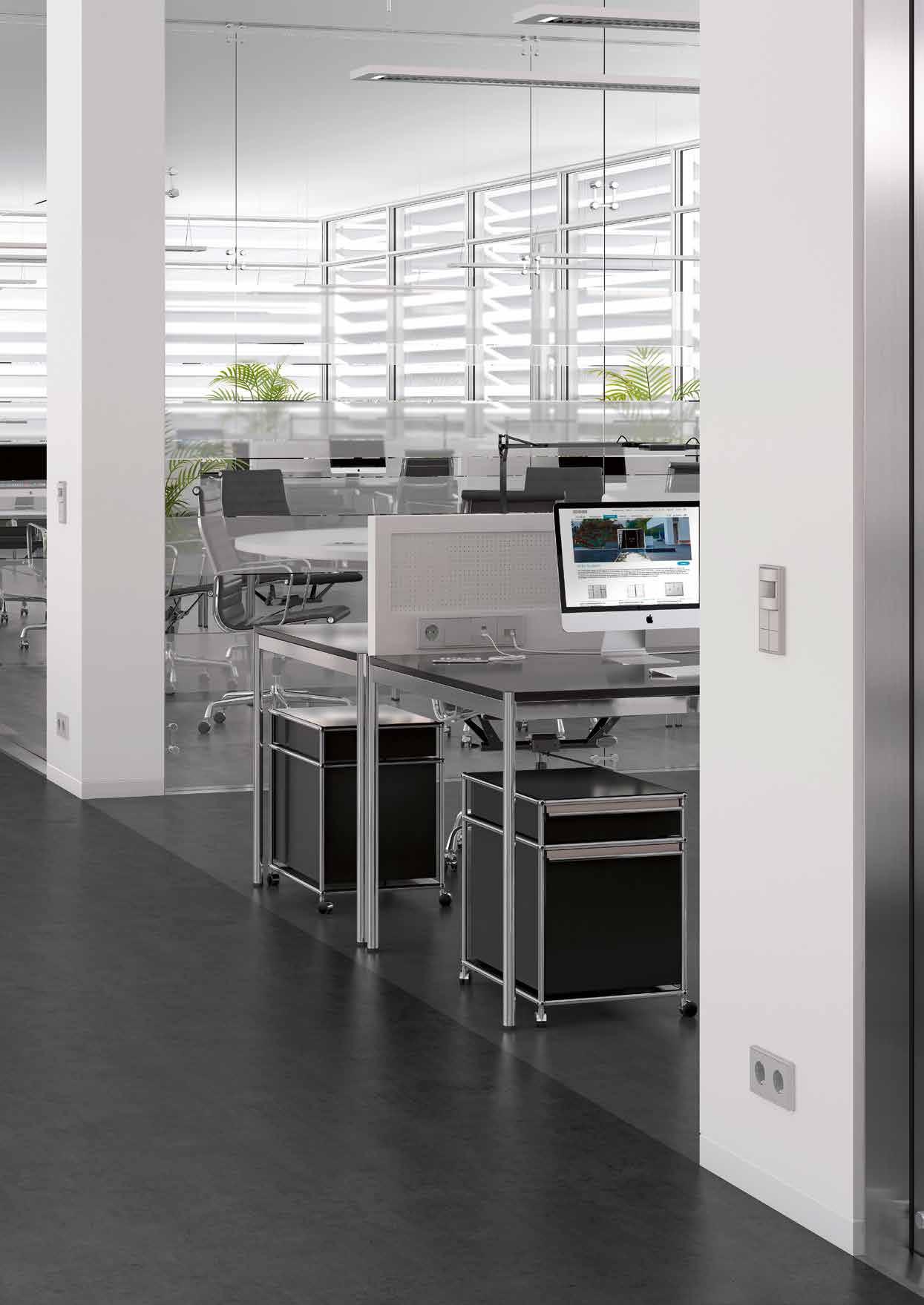
The software for the automatic switch is matched with respect to its important parameters to the JUNG KNX presence detectors, which allows simple initial start-up. Special performance characteristic: the integrated temperature sensor. The actual room temperature is measured with this. It can be reported to various KNX devices for heating regulation and air conditioning.
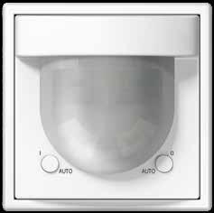 KNX AUTOMATIC SWITCH 1.10 M KNX AUTOMATIC SWITCH 2.20 M
ROOM AUTOMATION 131 130 ROOM AUTOMATION
KNX automatic switch in the 1.10 m and 2.20 m versions
KNX Automatic switches
Ref.-no.
KNX bus coupling unit 3 screw fixing only, without claws
Intended use
• Coupling of automatic switches (ref.-no.: ..3181.., ..3281..) to KNX systems
• Installation in flush box according to DIN 49073
Technical data
KNX medium: TP 256
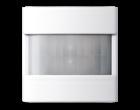
Rated voltage KNX: DC 21 ... 32 V SELV
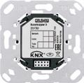
Ambient temperature: −25 ... +55 °C
Storage/transport temperature: −25 ... +70 °C
Protection class: III
KNX automatic switch 1.1 m for bus coupling unit 3 ref.-no.: 2073 U
ETS product family: Physical sensors
Product type: Movement
Intended use
2073 U
• Requirement-oriented control of lighting and other electrical loads in interior rooms
• Mounting on bus coupling unit 3 (ref.-no.: 2073 U)
Product characteristics
• Automatic switching of lighting depending on the thermal movement and ambient brightness
• 2 PIR sensors
• Detection range 180°
• Integrated brightness sensor
• Switch-off brightness can be set
• Output functions: Switching, staircase function, switching with forced position, value transmitter, light scene extension, operating mode setting for room temperature controller
• Extension of the detection area by way of operating several devices as main unit or extension unit
• Sensitivity can be set manually
• Status LEDs
• Manual switching on the device
• Up to half of the detection area can be screened off (cover or parameter setting)
Additional characteristics of "Universal" version:
• Manual operation with IR remote control possible (ref.-no.: KNX PM FB IR)
• 5 function blocks for motion detection each with 2 outputs
• Function blocks switchable, e.g. for day/night operation
• Brightness sensor function with 3 limiting values
• Alarm message in case the device is removed from the bus coupling unit
• Temperature measurement
Technical data
Current consumption KNX: 3 ... 10 mA
Ambient temperature: −5 ... +45 °C
Storage/transport temperature: −25 ... +70 °C
Relative humidity: 10 ... 100 % (no condensation)
Protection class: III
Mounting height: 1.10 m
Detection angle: 180°
Brightness sensor
Measuring range: approx. 1 ... 1,000 lx
Temperature sensor
Measuring range: −5 ... +45 °C
Accuracy: ± 1 K
132
KNX automatic switch 1.1 m
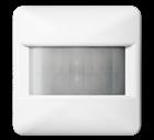
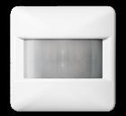
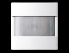
for AS and A ranges
Standard
Thermoplastic (breakproof) high-gloss
ivory
white
black
Thermoplastic (breakproof) lacquered
aluminium
champagne
mocha
matt lacquered
matt anthracite
Universal
Thermoplastic (breakproof) high-gloss
ivory
white
black
Thermoplastic (breakproof) lacquered
aluminium
champagne
mocha
matt lacquered
matt anthracite
for CD range
Standard
Thermoplastic (breakproof) high-gloss
ivory
white
grey
light grey
black
Universal
Thermoplastic (breakproof) high-gloss
ivory
white
grey
light grey
black
Automatic switches
Ref.-no.
A 3181
A 3181 WW
A 3181 SW
A 3181 AL
A 3181 CH
A 3181 MO
A 3181 ANM
A 3181-1
A 3181-1 WW
A 3181-1 SW
A 3181-1 AL
A 3181-1 CH
A 3181-1 MO
A 3181-1 ANM
CD 3181
CD 3181 WW
CD 3181 GR
CD 3181 LG
CD 3181 SW
CD 3181-1
CD 3181-1 WW
CD 3181-1 GR
CD 3181-1 LG
CD 3181-1 SW
133
KNX
KNX Automatic switches
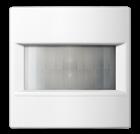
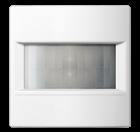
Ref.-no.
KNX automatic switch 1.1 m
for LS range
Standard
Thermoplastic (breakproof) high-gloss
steel (lacquered)
3181
3181 LG
3181
3181
3181 AN
3181 C
3181 AT Universal Thermoplastic (breakproof) high-gloss
3181-1 WW
3181-1 SW
3181-1
steel (lacquered)
(lacquered)
brass (lacquered)
brass (lacquered)
3181-1
3181-1 AN
3181-1 D
3181-1 C
3181-1 AT
134
ivory LS
white LS
light
LS
black LS
metal
AL
stainless
ES
anthracite
AL
dark
AL
classic
ME
antique
ME
ivory LS
white LS
light
LS
black LS
metal
AL
ES
AL
dark
AL
ME
antique
ME
3181 WW
grey
3181 SW
versions aluminium (lacquered)
(lacquered)
(lacquered)
3181 D
brass (lacquered)
brass (lacquered)
3181-1
grey
3181-1 LG
versions aluminium (lacquered)
stainless
anthracite (lacquered)
classic
Ref.-no.
KNX automatic switch 2.2 m for bus coupling unit 3 ref.-no.: 2073 U
Protection level IP 44 is ensured with sealing kit ref.-no. AS A 50 DS and "IP 44 frame" of the respective design range.
Standard (3281 ..): IP 44 suitable only for indoor installation

Universal (3281-1 ..): IP 44 suitable for indoor and outdoor installation
ETS product family: Physical sensors
Product type: Movement
Intended use
• Requirement-oriented control of lighting and other electrical loads
• Mounting on bus coupling unit 3 (ref.-no.: 2073 U)
Product characteristics
• Automatic switching of lighting depending on the thermal movement and ambient brightness
• 2 PIR sensors
• Detection range 180°
• Integrated brightness sensor
• Switch-off brightness can be set
• Output functions: Switching, staircase function, switching with forced position, value transmitter, light scene extension, operating mode setting for room temperature controller
• Extension of the detection area by way of operating several devices as main unit or extension unit
• Sensitivity can be set manually
• Status LEDs
• Manual switching on the device
Additional characteristics of "Universal" version:
• Manual operation with IR remote control possible (ref.-no.: KNX PM FB IR)
• Up to half of the detection area can be screened off (parameter setting)
• 5 function blocks for motion detection each with 2 outputs
• Function blocks switchable, e.g. for day/night operation
• Brightness sensor function with 3 limiting values
• Alarm message in case the device is removed from the bus coupling unit
• Temperature measurement
Technical data
Current consumption KNX: 3 ... 10 mA
Ambient temperature: −25 ... +55 °C
Storage/transport temperature: −25 ... +70 °C
Relative humidity: 10 ... 100 % (no condensation)
Protection class: III
Mounting height: 1.10 / 2.20 m
Detection angle: 180°
Brightness sensor
Measuring range: approx. 1 ... 1000 lx
Temperature sensor
Measuring range: approx. −20 ... 55 °C
Accuracy: ± 1 K
for AS and A ranges
Standard
Thermoplastic (breakproof) high-gloss
Thermoplastic (breakproof) lacquered
135 KNX
Automatic switches
ivory IP A 3281 white IP A 3281 WW black IP A 3281 SW
aluminium IP A 3281 AL champagne IP A 3281 CH mocha IP A 3281 MO
matt
IP A 3281 ANM
matt lacquered
anthracite
KNX Automatic switches
KNX automatic switch 2.2 m
(breakproof) high-gloss
Thermoplastic (breakproof) lacquered
for CD range
Thermoplastic (breakproof) high-gloss
Thermoplastic (breakproof) high-gloss
for LS range
Standard
Thermoplastic (breakproof) high-gloss
3281-1
3281-1 SW
LS 3281
3281 WW light grey
metal versions
aluminium (lacquered)
stainless steel (lacquered)
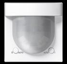
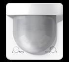
anthracite (lacquered)
dark (lacquered)
classic brass (lacquered)
3281 LG
LS 3281 SW
AL 3281
ES 3281
AL 3281 AN
AL 3281 D
ME 3281 C
antique brass (lacquered) ME 3281 AT
136
Ref.-no. Universal
ivory IP A
white IP A
WW black IP A
Thermoplastic
3281-1
3281-1
3281-1 SW
aluminium IP A
AL champagne IP A
mocha IP A
MO matt
matt
IP A 3281-1
3281-1
3281-1 CH
3281-1
lacquered
anthracite
ANM
Standard
ivory IP CD
white IP CD
grey IP CD
light
IP CD
black IP CD
3281
3281 WW
3281 GR
grey
3281 LG
3281 SW Universal
ivory IP CD
white IP CD
grey IP CD
light
IP CD
black IP CD
3281-1 WW
3281-1 GR
grey
3281-1 LG
IP
white IP
IP
black IP
ivory
LS
LS
IP
IP
IP
IP
KNX automatic switch 2.2 m
Universal Thermoplastic (breakproof) high-gloss
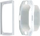
ivory
white
light grey
black
metal versions
aluminium (lacquered)
stainless steel (lacquered)
anthracite (lacquered)
dark (lacquered)
classic brass (lacquered)
antique brass (lacquered)
Sealing kit for automatic switches 2.2 m of the AS / A ranges
To obtain protection level IP 44
Automatic switches
KNX
IP LS 3281-1
IP LS 3281-1 WW
IP LS 3281-1 LG
IP LS 3281-1 SW
IP AL 3281-1
IP ES 3281-1
IP AL 3281-1 AN
IP AL 3281-1 D
ME 3281-1 C
ME 3281-1 AT
IP AS A 50 DS
Sealing kit for automatic switches 2.2 m of the CD and LS ranges
To obtain protection level IP 44
IP AS CD 50 DS
137
Ref.-no.
Consistent JUNG design also in the KNX temperature and ventilation control: the different room temperature controllers provide a healthy room climate in private and commercial buildings. Well-thought-out operating concepts support intuitive handling in each case.
Room thermostats
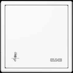
ROOM TEMPERATURE CONTROLLER
Standalone solution for heating and cooling for the residential and commercial areas. It is also possible to query conventional push-buttons and/ or window and door contacts as well as dew/condensation and leak sensors.
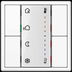
ROOM AUTOSTAT
Tamper-proof without a setting wheel and thus ideal for use in public buildings: the KNX room autostat with integrated push-button interface 4-gang for convenient temperature control.

CO2 SENSOR
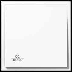
For automated ventilation applications, for temperature control and querying CO2 levels in room air. Also possible: Querying of conventional push-buttons and/or window and door contacts as well as dew/condensation and leak sensors.
ROOM TEMPERATURE CONTROLLER F 50
Controller for heating/cooling with integrated fan coil actuation. With variable display and operation options; self-explanatory symbols and coloured status and operation LEDs optimise the operation.
TEMPERATURE CONTROLLER FAN COIL
Controller for temperature and ventilation, mainly for the hotel business. Intuitive operating concept using capacitive sensor push-buttons. Clear display and unambiguous symbols make the selection from four operating modes easy.
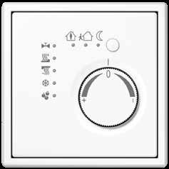
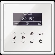 KNX room temperature controller fan coil
ROOM AUTOMATION 139 138 ROOM AUTOMATION
The functions of the F 50 room temperature controller
PUSH-BUTTON EXTENSION MODULE FOR ROOM TEMPERATURE CONTROLLER F 50
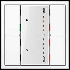
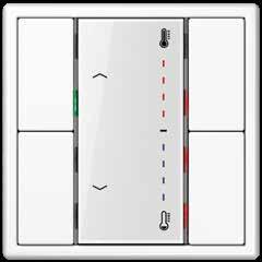
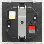
The functions can be extended by connecting the 1 to 4-gang push-button extension module, while at the same minimising the load on the bus. Particularly the option for installation of the extension module at a distance of up to 30 m provides more flexibility.
Display and adjustment of the operating mode
The temperature mode is selected as required using the “Comfort”, “Standby”, “Night Operation” and “Frost Protection” operating modes.
PRESENCE BUTTON
The user can decide between presence and absence with the Presence button. The appropriate symbols and coloured LEDs display the current status.
STANDBY/NIGHT OPERATION
At times of absence a choice between the “frost protection and night reduction operation modes can be made. Coloured LEDs next to the symbols indicate the relevant mode.
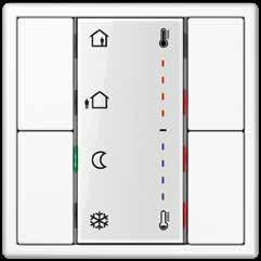
MOVE BLINDS/SHUTTERS
By changing settings, the push-button functions can be combined. Here, the operating mode changeover is changed to the move blinds/ shutters” push-button function.
SWITCH/DIM
With this setting, the switch/dim push-button functions on one side have been combined with a temperature setpoint shift on the other side.
OFFICE CORRIDOR OFFICE APPLICATION EXAMPLES KNX line 1 Room temperature controller F 50 2 Push-button extension module Room temperature controller ROOM 1 ROOM 2 ROOM 3 Room temperature controller Extension module Extension module max. 30m max. 30m KNX line 2 2 max. 30m
ROOM AUTOMATION 141 140 ROOM AUTOMATION
KNX Controllers
Ref.-no.
KNX temperature controller fan coil
Intended use
• Sensor module for operating electrical fan coil units in KNX installations
• Measurement and feedback control of the room temperature
• Installation in flush box according to DIN 49073
Product characteristics
• Real glass front panel
• 8 capacitive sensor buttons
• Internal temperature sensor
• External temperature sensor can be evaluated
• Control of fan coil units
• Heating and/or cooling mode
• Suitable for 2-pipe or 4-pipe systems
• Up to 3 fan speeds can be controlled
• Room temperature controller function
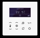
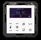
• Preselection of the current energy level either through the option of 4 operating modes in accordance with KNX standard or of 5 temperature profiles for use in hotels or similar sites
• Display for indication of actual temperature (°C or °F), fan speed, operating mode/profile
• 1 operating level and 2 menu levels
• Menu levels blockable
• 1 status LED (red/green/blue)
• Display brightness and contrast adjustable
• Duration of the display illumination up to 120 seconds
• Operation as extension unit for temperature controller possible
• Integrated bus coupling unit
Technical data
KNX medium: TP 256
Rated voltage KNX: DC 21 ... 32 V SELV
Current consumption KNX: 8 ... 17.5 mA
Protection class: III
Ambient temperature: −5 ... +45 °C
Storage/transport temperature: −20 ... +70 °C
for AS and A ranges
white TRD A 5248 WW
black TRD A 5248 SW
for LS range
white TRD LS 9248 WW
black TRD LS 9248 SW
142
Controllers
Ref.-no.
KNX
KNX room temperature controller module 2-gang including transparent cover and inlay with symbols
Intended use
• Single-room temperature control in KNX installations
• Operation of loads, e.g. light on/off, dimming, blinds up/down, calling up and saving light scenes, etc.
• Installation in flush box according to DIN 49073
Product characteristics
All buttons can be assigned with push-button sensor functions or functions for controller operation.
• KNX medium: TP 256
• Measurement of room temperature
• Room temperature control with setpoint value specification
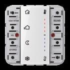
• Extension unit for room temperature controller
• Push-button functions switching, dimming, blind control, value transmitter, scene recall, etc.
• One or two functions per button
• Completion with cover kit 2-gang
• Inscription field can be illuminated
• Two red status LEDs per button – red, green or blue adjustable
• One operation LED as an orientation light and to indicate the programming status
– red, green or blue adjustable
• Brightness of status LEDs, operation LED and labelling field adjustable; switchable while in operation, e.g. during the night
• Disabling function: Disabling or change function mode of single or all button functions
• Alarm function, optional acknowledge by pressing any button
• Energy saving mode (for operation without controller function)
• Integrated bus coupling unit
• Connection for a push-button extension module, for extension with up to eight additional buttons
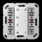
for AS and A ranges for cover kit 2-gang, ref.-no.: A 502 TSA ..
Cover kit see page 40
for CD range for cover kit 2-gang, ref.-no.: CD 502 TSA ..
Cover kit see page 46
for LS range for cover kit 2-gang, ref.-no.: LS 502 TSA ..
Cover kit see page 51
A 5178 TSM
CD 5178 TSM
LS 5178 TSM
143
KNX Controllers
KNX room temperature controller with integrated BCU with rotary knob for set point adjustment
Only with the ETS 3.0d version or later versions the full functionality will be available.
Intended use
• Single-room temperature control in KNX installations
• Installation in flush box according to DIN 49073
Product characteristics
• Measurement of room temperature and comparison with setpoint temperature
• Setpoint specification by selection of the operating mode
• Operating modes: Comfort, Standby, Night operation, Frost/heat protection
• Heating and cooling mode
• Heating and cooling with basic and additional step
• Setpoint adjustment
• Presence push-button
• Status LEDs
Technical data
KNX medium: TP 256
Rated voltage KNX: DC 21 ... 32 V SELV
Current consumption KNX: max. 10 mA Connection, KNX: terminal
Ambient temperature: −5 ... +45 °C
Storage/transport temperature: −25 ... +70 °C
144
KNX room temperature controller
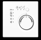
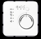
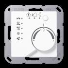
for AS and A ranges
Thermoplastic (breakproof) high-gloss
ivory
white
black
Thermoplastic (breakproof) lacquered
aluminium
champagne
mocha
matt lacquered
matt anthracite
for CD range
Thermoplastic (breakproof) high-gloss
Controllers
Ref.-no.
A 2178
A 2178 WW
A 2178 SW
A 2178 AL
A 2178 CH
A 2178 MO
A 2178 ANM
ivory 2178
white
grey
light grey
black
for LS range
Thermoplastic (breakproof) high-gloss
ivory
white
CD 2178 WW
CD 2178 GR
CD 2178 LG
CD 2178 SW
LS 2178
LS 2178 WW
light grey LS 2178 LG
black
metal versions
aluminium
stainless steel
anthracite (aluminium lacquered)
dark (aluminium lacquered)
chrome
classic brass
antique brass
LS 2178 SW
AL 2178
ES 2178
AL 2178 AN
AL 2178 D
GCR 2178
ME 2178 C
ME 2178 AT
145
KNX
KNX Controllers
KNX room temperature controller with integrated BCU with integrated push-button interface 4-gang with rotary knob for set point adjustment
Only with the ETS 3.0d version or later versions the full functionality will be available.
Intended use
• Single-room temperature control in KNX installations
• Type of loads for binary output: LED or electronic relais
• Installation in flush box according to DIN 49073
Product characteristics
• Measurement of room temperature and comparison with setpoint temperature
• Setpoint specification by selection of the operating mode
• Operating modes: Comfort, Standby, Night operation, Frost/heat protection
• Heating and cooling mode
• Heating and cooling with basic and additional step
• Setpoint adjustment
• Presence push-button
• Status LEDs
• Push-button interface with four inputs or two outputs (0.8 mA) and two inputs, e.g. for window contacts, push-buttons, LEDs, etc.
• Function of the inputs: switching, dimming, shutter control, light scene extension, brightness or temperature value transmitter
• Option: External temperature sensor (accessory ref.-no.: FF 7.8) connectable to input 4
Technical data
KNX medium: TP 256
Rated voltage KNX: DC 21 ... 32 V SELV
Current consumption KNX: max. 10 mA
Connection, KNX: terminal
Ambient temperature: −5 ... +45 °C
Storage/transport temperature: −25 ... +70 °C
Output current: 0.8 mA
Inputs and outputs
Cable type: J-Y(St)Y 2 x 2 x 0.8 mm
Cable length: max. 5 m
Temperature sensor cable length: max. 50 m
Use deep wall box for cables with 1.5 mm2
146
KNX room temperature controller
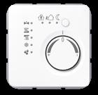
for AS and A ranges
Thermoplastic (breakproof) high-gloss
Thermoplastic (breakproof) lacquered
mocha
for CD range
Thermoplastic (breakproof) high-gloss
for LS range
Thermoplastic (breakproof) high-gloss
Ref.-no. 147
KNX Controllers
ivory A 2178 TS white A 2178 TS WW
A 2178 TS SW
black
aluminium A 2178 TS AL champagne A 2178 TS CH
A 2178 TS MO
A 2178 TS ANM
matt lacquered matt anthracite
ivory 2178 TS white CD 2178 TS WW grey CD 2178 TS GR light grey CD 2178 TS LG black CD 2178 TS SW
ivory LS 2178 TS white LS 2178 TS WW light grey LS 2178 TS LG black LS 2178 TS SW metal versions aluminium AL 2178 TS stainless steel ES 2178 TS anthracite (aluminium lacquered) AL 2178 TS AN dark (aluminium lacquered) AL 2178 TS D chrome GCR 2178 TS classic brass ME 2178 TS C antique brass ME 2178 TS AT
KNX Controllers
KNX room autostat with integrated BCU with integrated push-button interface 4-gang without rotary knob for set point adjustment without any operational elements
Only with the ETS 3.0d version or later versions the full functionality will be available.
Intended use
• Single-room temperature control in KNX installations
• Installation in flush box according to DIN 49073
Product characteristics
• Measurement of room temperature and comparison with setpoint temperature
• Setpoint specification by selection of the operating mode
• Operating modes: Comfort, Standby, Night operation, Frost/heat protection
• Heating and cooling mode
• Heating and cooling with basic and additional step
• Operation solely via the bus
• Push-button interface with four inputs or two outputs (0.8 mA) and two inputs, e.g. for window contacts, push-buttons, LEDs, etc.
• Function of the inputs: switching, dimming, shutter control, light scene extension, brightness or temperature value transmitter
• Option: External temperature sensor (accessory ref.-no.: FF 7.8) connectable to input 4
Technical data
KNX medium: TP 256
Rated voltage KNX: DC 21 ... 32 V SELV
Current consumption KNX: max. 7.5 mA
Connection, KNX: terminal
Ambient temperature: −5 ... +45 °C
Storage/transport temperature: −25 ... +70 °C
Output current: 0.8 mA
Inputs and outputs
Cable type: J-Y(St)Y 2 x 2 x 0.8 mm
Cable length: max. 5 m
Temperature sensor cable length: max. 50 m
Use of deep wall box (60 mm) is recommended for cables with 1.5 mm2
148
KNX room autostat
for AS and A ranges
Duroplastic (scratch-proof) glossy
ivory
white
black
Duroplastic lacquered
aluminium
champagne
mocha
Thermoplastic (breakproof) high-gloss
white
black
matt lacquered
matt anthracite
for CD range
Duroplastic (scratch-proof) glossy
Controllers
Ref.-no.
A 2178 ORTS
A 2178 ORTS WW
A 2178 ORTS SW
A 2178 ORTS AL
A 2178 ORTS CH
A 2178 ORTS MO
A 2178 BF ORTS WW
A 2178 BF ORTS SW
A 2178 BF ORTS ANM
ivory 2178 ORTS
white
grey
light grey
black
for LS range
Duroplastic (scratch-proof) glossy
ivory
white
light grey
black
metal versions
aluminium
stainless steel
anthracite (aluminium lacquered)
dark (aluminium lacquered)
chrome
classic brass
antique brass
CD 2178 ORTS WW
CD 2178 ORTS GR
CD 2178 ORTS LG
CD 2178 ORTS SW
LS 2178 ORTS
LS 2178 ORTS WW
LS 2178 ORTS LG
LS 2178 ORTS SW
AL 2178 ORTS
ES 2178 ORTS
AL 2178 ORTS AN
AL 2178 ORTS D
GCR 2178 ORTS
ME 2178 ORTS C
ME 2178 ORTS AT
149
KNX
KNX Controllers
KNX CO2 multi-sensor with integrated BCU with humidity sensor and room temperature controller with integrated push-button interface 2-gang
Intended use
• Measurement of CO2 concentration, relative air humidity and air temperature
• Output of the measured values as telegram to the bus, e.g. for controlling fans or window drives via KNX telegrams
• Single-room temperature control in KNX installations
• Installation in flush box according to DIN 49073
Product characteristics
• Limit value monitoring for CO2 concentration (max. 4 threshold values) and air humidity (max. 2 threshold values)
• Dew point alarm e.g. for cooling blankets and conservatories, to avoid mould formation
• Two binary inputs for connection of floating contacts e.g. buttons, switches, window contacts
• Logic gates for simple gating functions
Technical data
KNX medium: TP 256
Rated voltage KNX: DC 21 ... 32 V SELV
Current consumption KNX: typical 12.5 mA max. 25 mA (4 s/15 s as a cycle)
Connection, KNX: terminal Protection class: III
Ambient temperature: −5 ... +45 °C
Binary inputs
Cable length: max. 5 m
Cable type: J-Y(St)Y 2 x 2 x 0.8 mm
CO2 sensor
Measuring range: 0 ... 2000 ppm
Humidity sensor
Measuring range: 10 ... 95 % relative humidity (r. h.)
Temperature sensor
Measuring range: −5 ... +45 °C
150
Controllers
Ref.-no.
KNX CO2 multi-sensor
for AS and A ranges
Duroplastic (scratch-proof) glossy
ivory CO2 A 2178
white CO2 A 2178 WW
black CO2 A 2178 SW
Duroplastic lacquered
aluminium CO2 A 2178 AL
champagne
mocha
Thermoplastic (breakproof) high-gloss
CO2 A 2178 CH
CO2 A 2178 MO
white CO2 A 2178 BF WW
black CO2 A 2178 BF SW
matt lacquered
matt anthracite
for CD range
Duroplastic (scratch-proof) glossy
CO2 A 2178 BF ANM
ivory CO2 CD 2178
white CO2 CD 2178 WW
grey CO2 CD 2178 GR
light grey
CO2 CD 2178 LG
black CO2 CD 2178 SW
for LS range
Duroplastic (scratch-proof) glossy
ivory CO2 LS 2178
white CO2 LS 2178 WW
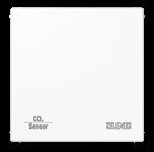
light grey
CO2 LS 2178 LG
black CO2 LS 2178 SW
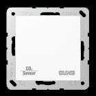
metal versions
aluminium
stainless steel
anthracite (aluminium lacquered)
dark (aluminium lacquered)
CO2 AL 2178
CO2 ES 2178
CO2 AL 2178 AN
CO2 AL 2178 D
chrome CO2 GCR 2178
classic brass
antique brass
CO2 ME 2178 C
CO2 ME 2178 AT
151
KNX
System devices
The JUNG KNX portfolio has the right product for all demands. The example design of a KNX installation with the individual system devices makes the various options of transmission paths and types of programming access clear.
line
Internet
1 LAN router
2 Computer with installed ETS
3 IPR 300 SREG as area coupler

4 IPR 300 SREG as line coupler
5 Line coupler

6 Radio converter
7 Power supply
8 IPS 300 SREG incl. IPS Remote
9 Node 10 USB interface 11 KNX RF
LAN
KNX
2 B) Commissioning via IP using KNX IP Router or IP interface A) Remote maintenance via IPS Remote and myJUNG 2 D) Commissioning using KNX RF wireless USB stick 2 C)
USB interface 5 7 9 5 7 9 10 5 7 9 5 7 9 5 9 7 4 7 3 7 3 7 6 11 9 2 8 SYSTEM DEVICES 153 152 SYSTEM DEVICES
Commissioning via
Remote maintenance of the KNX system
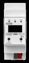
Simple and secure remote maintenance and programming of all KNX components: IPS-Remote makes it possible. Remote maintenance is convenient for the expert and cost-effective for the building owner.
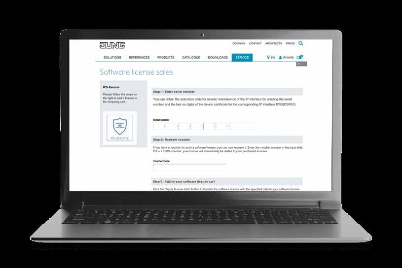
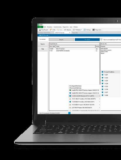
With encrypted remote maintenance via IPSRemote, system integrators only access the customer's KNX components. Time-consuming and cost-intensive journeys are eliminated. The necessary requirements for this are clear: The ETS app IPS Remote, the IP interface IPS 300 SREG or a power supply with IP interface and the remote maintenance licence IPS-L bound to the respective interface. System integrators acquire these via their myJUNG access
– also subsequently. Once linked, professional installers maintain the KNX components behind the IP interface as usual via ETS. If necessary, the customer grants access to the system integrator – this is done via Smart Visu Server or via connection to a push-button sensor. In this way, the control always remains with the customer. Remote maintenance focuses exclusively on the KNX system.
IPS 300 SREG (or 20320 1S IPS R) KNX
IPS-REMOTE SOFTWARE LICENCE IPS-L IN THE MYJUNG PORTAL
JUNG.DE/MYJUNG SYSTEM DEVICES 155 154 SYSTEM DEVICES
System devices with KNX Secure
KNX RF RADIO MEDIA COUPLER
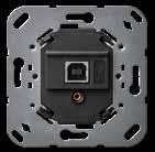
The KNX wireless radio converter is the link between a specific KNX RF environment and a KNX TP installation. In this way, communication can take place easily between wired and wireless devices.
JUNG provides KNX system devices with KNX Secure and brings important areas together. All components ensure data security and reliably control the complete building technology.
The KNX power supply with IP interface brings together what is needed in every KNX installation: Power supply and interface. This makes it easier to select components already at the planning stage.
But JUNG also provides secure interfaces for all other areas in the smart building. They protect the data exchange using KNX Secure and reliably control the complete building technology.
KNX AREA/LINE COUPLER
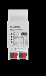
The coupler makes the data connection between two KNX lines and ensures a galvanic separation between these lines. The coupler is allocated logically to the subordinate line.
KNX USB DATA INTERFACE
The KNX USB data interface connects a PC with KNX systems. This allows addressing, setting and diagnosis to take place in the KNX system.
KNX USB DATA INTERFACE (FLUSH-MOUNTED)
Also available as flush-mounted insert: the USB data interface allows the connection of a PC for the addressing, programming and diagnosis of KNX components.
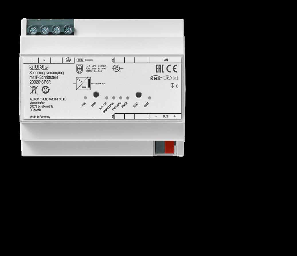
KNX IP INTERFACE
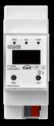
The IP interface connects KNX devices via the network (IP) with the PC or other data processing devices. It connects KNX lines over a fast IP backbone including with visualisation.
KNX IP ROUTER
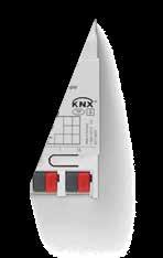
KNXnet/IP routing for communication between KNX lines, areas and systems via the IP network: the IP router also connects KNX devices with the local network. Furthermore, it can be operated as a KNX area/line coupler or data interface.
KNX POWER SUPPLY WITH IP INTERFACE
SYSTEM DEVICES 157 156 SYSTEM DEVICES
KNX System components
KNX power supplies 160 mA, 320 mA, 640 mA
Intended use
• Supplying KNX devices with bus voltage
• Supplying devices with DC voltage
• Mounting on DIN rail according to EN 60715 in distribution boxes
Product characteristics
• Output with integrated choke for supplying KNX bus lines
• Output DC 30 V for supplying additional devices
• Nominal current can be subdivided to outputs as desired
• Reset button
• Short-circuit proof
• Overvoltage proof
• No-load protection
• Suitable for operation in systems with emergency power supply
• Floating signal contact for operating and diagnostic message
• Can be connected in parallel with identical power supply (until the maximum short-circuit current is reached)
KNX power supply, 160 mA
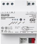
Rail mounting device, 4 rail units
ETS product family: System components
Product type: Power supply
Technical data
Rated voltage: AC 200 ... 240 V ~
Mains frequency: 50/60 Hz
Power loss (max. load on all outputs): max. 1.5 W
Efficiency: approx. 76 %
Rated voltage: DC 240 ... 250 V
KNX
KNX medium: TP 256
Bus output voltage: DC 28 ... 31 V SELV
Output current: 160 mA (all outputs)
Short-circuit current: max. 1 A
Parallel operation with identical power supply: yes
Signal output
Switching voltage AC: AC 12 ... 230 V ~
Switching voltage DC: DC 2 ... 30 V
Switching current: 5 mA ... 2 A
Ambient temperature: −5 ... +45 °C
Storage/transport temperature: −25 ... +75 °C
Relative humidity: max. 93 % (no condensation)
Mounting width: 72 mm (4 rail units)
20160 REG
158
Ref.-no.
System components
KNX power supply, 320 mA

Rail mounting device, 4 rail units
ETS product family: System components
Product type: Power supply 20320 REG
Technical data
Rated voltage: AC 200 ... 240 V ~
Mains frequency: 50/60 Hz
Power loss (max. load on all outputs): max. 1.8 W
Efficiency: approx. 84 %
Rated voltage: DC 240 ... 250 V
KNX KNX medium: TP 256
Bus output voltage: DC 28 ... 31 V SELV
Output current: 320 mA (all outputs)
Short-circuit current: max. 1 A
Parallel operation with identical power supply: yes
Signal output
Switching voltage AC: AC 12 ... 230 V ~
Switching voltage DC: DC 2 ... 30 V
Switching current: 5 mA ... 2 A
Ambient temperature: −5 ... +45 °C
Storage/transport temperature: −25 ... +75 °C
Relative humidity: max. 93 % (no condensation)
Mounting width: 72 mm (4 rail units)
KNX power supply, 640 mA
Rail mounting device, 4 rail units
ETS product family: System components
Product type: Power supply 20640 REG
Technical data
Rated voltage: AC 200 ... 240 V ~
Mains frequency: 50/60 Hz
Power loss (max. load on all outputs): max. 2.9 W
Efficiency: approx. 87 %
Rated voltage: DC 240 ... 250 V
KNX KNX medium: TP 256
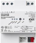
Bus output voltage: DC 28 ... 31 V SELV
Output current: 640 mA (all outputs)
Short-circuit current: max. 1.5 A
Parallel operation with identical power supply: yes
Signal output
Switching voltage AC: AC 12 ... 230 V ~
Switching voltage DC: DC 2 ... 30 V
Switching current: 5 mA ... 2 A
Ambient temperature: −5 ... +45 °C
Storage/transport temperature: −25 ... +75 °C
Relative humidity: max. 93 % (no condensation)
Mounting width: 72 mm (4 rail units)
Ref.-no. 159
KNX
KNX System components
KNX power supply, 1280 mA
Rail mounting device, 6 rail units
ETS product family: System components
Product type: Power supply
Intended use
• Supplying KNX devices with bus voltage
• Supplying devices with DC voltage
• Mounting on DIN rail according to EN 60715 in distribution boxes
Product characteristics
• Output with integrated choke for supplying KNX bus lines
• Output DC 30 V for supplying additional devices
• Nominal current can be subdivided to outputs as desired
• Reset button
• Short-circuit proof
• Overvoltage proof
• No-load protection
• Suitable for operation in systems with emergency power supply
• Floating signal contact for operating and diagnostic message
Technical data
Rated voltage: AC 200 ... 240 V ~
Mains frequency: 50/60 Hz
Power loss (max. load on all outputs): max. 6.4 W
Efficiency: approx. 86 %
Rated voltage: DC 240 ... 250 V
KNX
KNX medium: TP 256
Bus output voltage: DC 28 ... 31 V SELV
Output current: 1,280 mA (all outputs)
Short-circuit current: max. 3 A
Parallel operation with identical power supply: no
Signal output
Switching voltage AC: AC 12 ... 230 V ~
Switching voltage DC: DC 2 ... 30 V
Switching current: 5 mA ... 2 A
Ambient temperature: −5 ... +45 °C
Storage/transport temperature: −25 ... +75 °C
Relative humidity: max. 93 % (no condensation)
Mounting width: 108 mm (6 rail units)
21280 REG
160
Ref.-no.
System components
KNX power supply 320 mA with IP interface
Rail mounting device, 6 rail units
Project design and commissioning with ETS5 or a more recent version.
ETS product family: System components
Product type: Power supply
Intended use
• Supplying KNX devices with bus voltage
• Connection between KNX devices and PC or other data processing devices via IP
• Operation as data interface
• Mounting on DIN rail according to EN 60715 in distribution boxes
Product characteristics
• Output with integrated choke for supplying KNX bus lines
• Reset of KNX lines via reset button or communication object
• Short-circuit proof
• Overvoltage proof
• No-load protection
• KNX Data Secure compatible with ETS 5.7.3 or higher
• KNX IP Secure compatible with ETS 5.7.3 or higher
• LED display for KNX communication, Ethernet communication and programming mode
• Configuration via ETS
• SNTP server
• Max. 8 connections to IP terminal devices, e.g. for simultaneous visualisation and configuration
• Electrical isolation between KNX and IP network
Application program A (delivery state):
• Presence control: with key card holder or presence detector
• Welcome/Goodbye scenes
Or alternatively application program B (V02 or higher and in combination with remote access licence ref.-no. IPS-L):
• Encrypted access to KNX devices for configuration and maintenance outside the local network
• Enabling access via communication objects
• Feedback on access and programming processes via communication objects
Technical data
Rated voltage: AC 110 ... 240 V (± 10 %)
Mains frequency: 50/60 Hz
Power loss (max. load on all outputs): max. 1.4 W
Efficiency: approx. 88 %
Rated voltage: DC 230 V (± 10 %)
Rated capacity: 12 W
KNX KNX medium: TP 256
Bus output voltage: DC 28 ... 31 V SELV
Output current: 320 mA
Short-circuit current: max. 1 A
Parallel operation with identical power supply: no
Connection, KNX: terminal
IP communication: Ethernet 10/100 BaseT (10/100 Mbit/s)
IP connection: RJ45 socket
Ambient temperature: −5 ... +45 °C
Storage/transport temperature: −25 ... +75 °C
Relative humidity: max. 93 % (no condensation)
Mounting width: 108 mm (6 rail units)
Connection mode: screw terminals
single wire: 1 x 1 ... 4 mm2
stranded without ferrule: 1 x 1 ... 4 mm2
stranded with ferrule: 1 x 1 ... 2.5 mm2
161
Ref.-no.
KNX
N 20320 1S IPS R
KNX System components
Ref.-no.
KNX USB data interface
Rail mounting device, 2 rail units
Intended use
• Connecting PCs to KNX systems
• Addressing, programming and diagnostics of KNX devices
• KNX Data Secure compatible with ETS 5.7.3 or higher
• Support of long frames for ETS5
• Installation in small distributor board on DIN rail according to DIN EN 60715
Product characteristics
• Connection with device connection terminal
• Electrical separation of KNX and USB
• Temporary operation in unmounted condition permissible
• The firmware in the USB data interface can be updated via the ETS product database
• Power supply exclusively via the USB port
Technical data
KNX medium: TP 256
Power supply: via USB port of the PC Connection
Connection, KNX: terminal
USB port: USB socket, type B
Transfer rate: 9600 Baud
Transmission protocol: compatible with USB 1.1/2.0
Length of USB cable: max. 5 m
Ambient temperature: −5 ... +45 °C
Storing temperature: −25 ... +70 °C
Protection class: II
Mounting width: 36 mm (2 rail units)
KNX USB data interface
Intended use
• Connecting PCs to KNX systems
• Addressing, programming and diagnostics of KNX devices
• KNX Data Secure compatible with ETS 5.7.3 or higher
• Support of long frames for ETS5
• Installation in flush box according to DIN 49073
Product characteristics
• Connection with device connection terminal
• Electrical separation of KNX and USB
• Temporary operation in unmounted condition permissible
• The firmware in the USB data interface can be updated via the ETS product database
• Power supply exclusively via the USB port
Technical data
KNX medium: TP 256
Power supply: via USB port of the PC Connection
Connection, KNX: terminal USB port: USB socket, type B
Transfer rate: 9600 Baud
Transmission protocol: compatible with USB 1.1/2.0
Length of USB cable: max. 5 m
Ambient temperature: −5 ... +45 °C
Storing temperature: −25 ... +70 °C
Protection class: II
162
2131 USBS REG
2131 USBS
Centre plate (screw fixing) for USB data interface ref.-no.: 2131 USBS
for AS and A ranges
Duroplastic (scratch-proof) glossy
ivory
white
black
Duroplastic lacquered
aluminium
champagne
mocha
Thermoplastic (breakproof) high-gloss
ivory
black
matt lacquered
matt snow white
matt graphite black
matt anthracite
for CD range
Thermoplastic (breakproof) high-gloss ivory
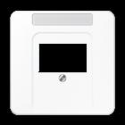
light grey
black
Centre plate (screw fixing) with inscription field 6 x 37 mm
Thermoplastic (breakproof) high-gloss
ivory
System components
Centre plate (screw fixing) for USB data interface ref.-no.: 2131 USBS for LS range
Thermoplastic (breakproof) high-gloss
ivory
aluminium
anthracite (aluminium lacquered)
dark (aluminium lacquered)
Ref.-no. 163
KNX
P A 569 PLT
P A 569 PLT WW
A
569 PLT SW
P L A
AL
569 PLT
P A
CH
569 PLT
A
569 PLT MO
L A 569 BFPLT
white L A 569 BFPLT WW
L
A 569 BFPLT SW
A
N
569 BFPLT WWM
N A
569 BFPLT SWM
A
569 BFPLT ANM
L
T
L CD
T WW
L CD
T GR
569
white
569
grey
569
L CD
T LG
569
L CD
T SW
569
L
569 TNA
CD
TNA WW
white L
569
L
T
L LS
T WW
L LS
T LG
L LS
T SW
LS 969
white
969
light grey
969
black
969
matt lacquered
N LS
T WWM
matt snow white
969
N LS
T SWM
matt graphite black
969
metal versions
P L AL 2969 T
L ES 2969 T
stainless steel
AL 2969 T AN
AL 2969 T D
GCR 2969 T
ME
T C
ME
T AT
chrome
classic brass P
2969
antique brass
2969
KNX RF System components
KNX RF radio USB stick
Intended use
Ref.-no.
USB 2130 RF
• PC interface for the addressing, programming and diagnostics of KNX RF devices
• USB stick for coupling to a PC with a Windows-based operating system
Product characteristics
• Commissioning, programming, visualisation and diagnostics of KNX RF devices
• Automatic installation of PC communication via HID profile
Technical data
Rated voltage: DC 5 V
USB version: 2.0
Connection USB: type A
Ambient temperature: −10 ... +70 °C
Relative humidity: max. 80 % (no condensation)
Radio frequency: 868.0 ... 868.6 MHz
Transmitting power: max. 20 mW
Transmission range in free field: typical 100 m
KNX RF radio converter
Project design and commissioning with ETS5 or a more recent version.
Intended use
• KNX medium: TP 256
• KNX Data Secure compatible with ETS 5.7.3 or higher
• Connection of KNX radio networks with cabled KNX lines
MK 100 RF
• Extension of the radio range in KNX radio networks (repeater operation, external power supply with 24 V AC/DC, e.g. ref.-no. NT 2415 REG VDC)
• Installation in flush box according to DIN 49073 in combination with a suitable cover
164
System components
KNX IP interface
Rail mounting device, 2 rail units
Project design and commissioning with ETS5 or a more recent version.
Intended use
• Connection between KNX devices and PC or other data processing devices via IP
• Operation as data interface
• Mounting on DIN rail according to EN 60715 in distribution boxes
Product characteristics
• KNX Data Secure compatible with ETS 5.7.3 or higher
• KNX IP Secure compatible with ETS 5.7.3 or higher

• Max. 48 telegrams per second in IP secure mode
• LED display for KNX communication, Ethernet communication and programming mode
• Configuration via ETS, Telnet or software tool
• SNTP server, buffered
• Commissioning with display support
• Max. 8 connections to IP terminal devices, e.g. for simultaneous visualisation and configuration
• Outage message of the KNX system to the IP system
• Electrical isolation between KNX and IP network
• Power consumption max. 1 W
V05 or higher and in combination with remote access licence (ref.-no. IPS-L):
• Encrypted access to KNX devices for configuration and maintenance outside the local network
• Enabling access via communication objects
• Feedback on access and programming processes via communication objects
Technical data
KNX medium: TP 256
Rated voltage KNX: DC 21 ... 32 V SELV Connection, KNX: terminal
Current consumption: max. 20 mA
Power consumption: max. 1 W
IP communication: Ethernet 10/100 BaseT (10/100 Mbit/s)
IP connection: RJ45 socket
Resolution: 128 x 64, OLED display
Ambient temperature: −5 ... +45 °C
Storage/transport temperature: −25 ... +70 °C
Relative humidity: max. 95 %
Mounting width: 36 mm (2 rail units)
Remote access licence for IP interface ref.-no.: IPS 300 SREG (V05 or higher) for power supply with IP interface ref.-no.: 20320 1S IPS R (V02 or higher)

Remote access to the building technology via JUNG server in Germany. In combination with IP interface (ref.-no. IPS 300 SREG) or power supply with IP interface (ref.-no. 20320 1S IPS R):
• Encrypted access to KNX devices for configuration and maintenance outside the local network
• Enabling access via communication objects
• Feedback on access and programming processes via communication objects
165
Ref.-no.
KNX
IPS 300 SREG
N IPS-L
KNX System components
Ref.-no.
KNX IP router
Rail mounting device, 2 rail units
Project design and commissioning with ETS5 or a more recent version.
ETS product family: System components
Product type: IP router
Intended use
• Connection between KNX devices and PC or other data processing devices via IP
• Operation as KNX area/line coupler or data interface
• Mounting on DIN rail according to EN 60715 in distribution boxes
Product characteristics
• KNXnet/IP routing for communication between KNX lines, areas and systems via IP network
• KNX Data Secure compatible with ETS 5.7.3 or higher
• KNX IP Secure compatible with ETS 5.7.3 or higher
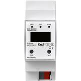
• Telegramm forwarding and filtering according to physical address or group address
• Max. 48 telegrams per second in IP secure mode
• LED display for KNX communication, Ethernet communication and programming mode
• Configuration via ETS, Telnet or software tool
• SNTP server, buffered
• Commissioning with display support
• Max. 8 connections to IP terminal devices, e.g. for simultaneous visualisation and configuration
• Outage message of the KNX system to the IP system
• Electrical isolation between KNX and IP network
• Power consumption max. 1 W
Technical data
KNX medium: TP 256
Rated voltage KNX: DC 21 ... 32 V SELV
Connection, KNX: terminal
Current consumption: max. 20 mA
Power consumption: max. 1 W
IP communication: Ethernet 10/100 BaseT (10/100 Mbit/s)
IP connection: RJ45 socket
Resolution: 128 x 64, OLED display
Ambient temperature: −5 ... +45 °C
Storage/transport temperature: −25 ... +70 °C
Relative humidity: max. 95 %
Mounting width: 36 mm (2 rail units)
166
IPR 300 SREG
System components
KNX area / line coupler
Rail mounting device, 2 rail units
ETS product family: System components
Product type: Line coupler
• KNX Data Secure compatible with ETS 5.7.3 or higher
Function
The coupler connects two KNX data lines and ensures the electrical separation of these lines from one another. The definite functions of the device are defined by addressing and parameterisation.
Line coupler
Connection of a line with a main line. Alternatively with or without filter function. The coupler belongs logically to the subordinate line (here: line).
Area coupler
Connection of a main line and an area line. Alternatively with or without filter function. The coupler belongs logically to the subordinate line (here: main line).
Amplifier
Preparation and repetition of telegrams on a line, no filter function. Division of a line into max. 4 independent line segments (max. 3 line amplifiers connected in parallel per line). Each line segment requires a separate power supply including a choke.
Technical data
KNX medium: TP 256
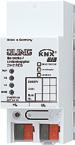
Power supply: DC 21 ... 32 V from superordinate line
Current consumption superordinate line: approx. 6 mA
subordinate line: approx. 8 mA
Connection mode: connection terminal
Mounting: on DIN rail
Ambient temperature: −5 ... +45 °C
Storing temperature: −25 ... +70 °C
Protection class: III acc. EN 61 140
Mounting width: 36 mm (2 rail units)
167
Ref.-no.
KNX
2142 REG
KNX Sonos Gateway
Control volume, skip a song and much more: The JUNG KNX Sonos Gateway makes it possible.
Multiroom sound in the whole house, operated through JUNG control elements: by setting up dynamic groups, up to five zones can each be equipped with a master. These zones can then in turn be networked with up to five slave devices.
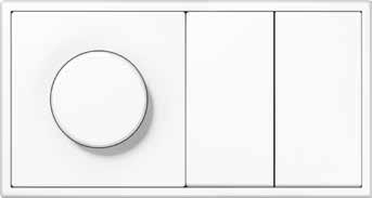
The new JUNG KNX Sonos Gateway connects the intelligent KNX technology with Sonos multiroom sound. Intuitively controlled using KNX sensors or smartphone/tablet in connection with the Smart VisuServer: up to 30 Sonos
devices can be controlled via various operating elements. Title, artist and album are also shown on the displays of room controllers or Smart Control.
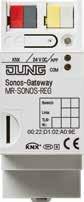
Zone 1 Bathroom Zone 2 Kitchen Zone 1 Bathroom Zone 2 Kitchen KNX line LAN
168 MULTIROOM/AUDIO
KNX Sonos gateway
Rail mounting device, 2 rail units
ETS product family: Multimedia
Product type: Multiroom
Intended use
• Controlling of Sonos audio devices via KNX
• Installation in distribution boxes on DIN rail according to EN 60715
Product characteristics
System components
Ref.-no.
MR-SONOS-REG
• Control of up to 30 Sonos devices via KNX devices, independent of the Sonos App
• Dynamic group creation of up to 10 zones with one master and five slave devices each via KNX objects
• Party mode: same music for all rooms
• Volume control for master, slaves and the whole group
• Control of play lists
• Playing music from microSD card (not included) in the Sonos gateway
• Title, artist and album on KNX text objects
• Integrated data network switch with two RJ45 terminals
• Requires ETS version 4.2 or 5.0.2 or higher
Technical data
KNX medium: TP 256
External supply
Rated voltage: DC 24 ... 30 V ± 10 % Connection: connecting terminal yellow/white
Power consumption: typical 2 W (at DC 24 V, two Ethernet cables connected)
IP communication: Ethernet 10/100 BaseT (10/100 Mbit/s)
IP connection: 2 x RJ45
Protocols: ARP, ICMP, IGMP, UDP/IP, DHCP, AutoIP, KNXnet/IP (Core, Device Management)
Memory card: max. 32 GB microSDHC
Ambient temperature: 0 ... +45 °C
Storage/transport temperature: −25 ... +70 °C
Mounting width: 36 mm (2 rail units)
Rated voltage KNX: DC 21 ... 32 V SELV Connection, KNX: terminal
169
KNX
KNX DALI gateway TW
Illuminate rooms in a targeted manner and use matching colour temperatures to promote performance of people. The KNX DALI gateway TW forms the interface to the control of DALI luminaires in a KNX installation (for max. 64 DALI nodes in max. 32 groups). As well as the regular brightness control, the control of the colour temperature of white light is also performed. The lighting can thus be adjusted as required at any time.
The basic idea of Tunable White is to control the colour temperature dynamically and seamlessly from warm white (1,000 Kelvin) to cold white (10,000 Kelvin). By adapting the colour temperature to the room, the perceived quality improves. Tunable White thus stands for a high level of lighting comfort thanks to its excellent colour reproduction –
but also above all for its ability to adapt artificial light dynamically to human biorhythms. This can provably improve human performance and have a positive effect on their health. The JUNG KNX DALI gateway TW is the first KNX device that provides this capability with such scope and supports the DALI 2 standard.
COLOUR TEMPERATURE AND BRIGHTNESS
Using the KNX DALI gateway TW, colour temperature and brightness can be set independently of each other or combined as desired. In this way, the behaviour of an incandescent lamp can be adjusted by changing the colour temperature to the warmer range when dimming and changing to the colder range when making brighter.
170 COMMUNICATION/GATEWAYS
System components
KNX DALI gateway TW
Rail mounting device, 4 rail units with manual electronic operation and LED status indication
ETS product family: Illumination
Product type: Dimmer New in V 02: compatible with DALI-2 acc. to IEC 62386
Intended use
• Controlling of luminaires and other applications with DALI operating device in KNX installations e.g. electronic ballast
• Mounting on DIN rail according to EN 60715 in distribution boxes
Product characteristics
• Control of up to 64 DALI devices in up to 32 groups
• Setting of colour temperature for luminaires with DALI Device Type 8 for tunable white acc. to IEC 62386-209
• Suitable for operation in emergency lighting systems
• compatible with DALI-2 acc. to IEC 62386
• Individual, group or central addressing
• 16 light scenes
• Effect control for dynamic lighting effects or colour games
• Read out DALI device state via KNX, e.g. brightness or luminaire error
• Manual operation of the DALI groups
• Feedback of switching state and brightness value in bus and manual mode
• Central switching function
• Disabling function for each DALI group
• Restraint function
• Collective feedback
• Separate ON and OFF delay
• Corridor function: when combined with motion detectors, reduced continuous lighting, if no motion is detected
• Staircase lighting timer with pre-warning function
• Online or offline project design of the DALI devices with ETS plug-in
• Short-circuit protection
• Surge voltage protection
• Overload protection
• Operating hours counter
• Signal of the global switching status of the DALI devices, e.g. to switch off the mains voltage of the DALI devices to avoid standby losses
• An individual DALI device can be exchanged during operation without software
• Linear or logarithmic dimming characteristic can be selected
Technical data
Rated voltage: AC 110 ... 240 V ~, 50/60 Hz
Rated voltage: DC 110 ... 240 V
Power loss: max. 3 W
Ambient temperature: −5 ... +45 °C
Storage/transport temperature: −25 ... +70 °C
Rated voltage DALI: DC 16 V
Number of DALI devices: max. 64
DALI transmission rate: 1.2 kbit/s
DALI protocol: EN 62386
Cable type: Sheathed cable 230 V, e,g. NYM
Cable length DALI with 1.5 mm2: max. 300 m with 1.0 mm2: max. 238 m with 0.75 mm2: max. 174 m with 0.5 mm2: max. 116 m
Mounting width: 72 mm (4 rail units)
Connection, power supply and DALI
Connection mode: screw terminals single wire: 1 x 0.5 ... 4 mm2
stranded without ferrule: 1 x 0.5 ... 4 mm2
stranded with ferrule: 1 x 0.5 ... 2.5 mm2
KNX medium: TP 256
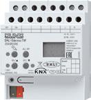
Rated voltage KNX: DC 21 ... 32 V SELV
Power consumption KNX: typical 150 mW
Connection, KNX: terminal
171 KNX
Ref.-no.
2099 REGHE
The new generation of the KNX switch and blind actuators
KNX
1 Easier handling
2 Convenient commissioning
3 Secure KNX connection
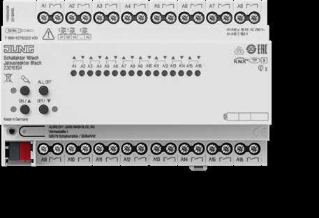
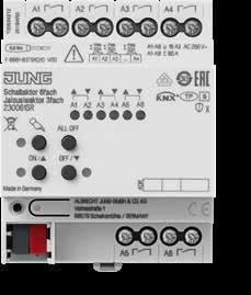
4 Improved readability without backlighting
5 More efficient wiring
The JUNG KNX switch and blind actuators have a holistically improved concept. They simplify installation and increase security: they work with KNX Data Secure and effectively encrypt all KNX telegrams as a result. You can get updates via the ETS Service app.
The JUNG KNX actuators in the 6-gang, 16-gang and 24-gang versions work with KNX Secure. Telegrams on the twisted pair line are tap-proof. The actuators receive updates via the ETS Service app. KNX new-generation actuators are more compact thanks to their single-layer design. They are clear and easy to read and their installation is simple.
Furthermore, once configured, actuators, for example for controlling blinds, can be multiplied using the teaching function: Installed once, copied several times – the work in the property is done quickly. Due to the bistable relays of the actuators, the power loss is reduced to a minimum. This makes the actuators more energy efficient.
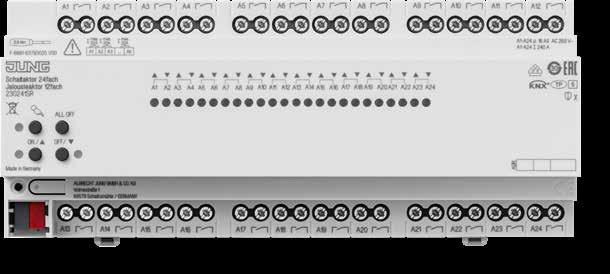
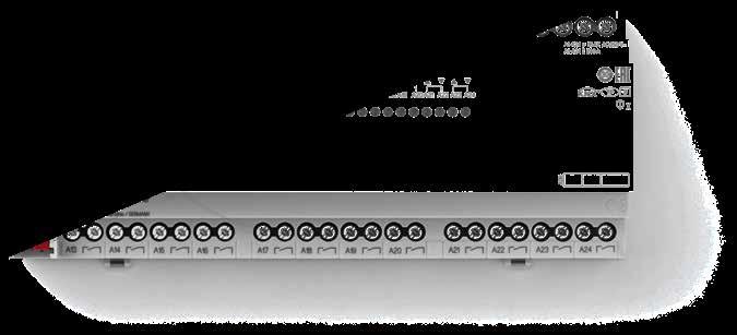
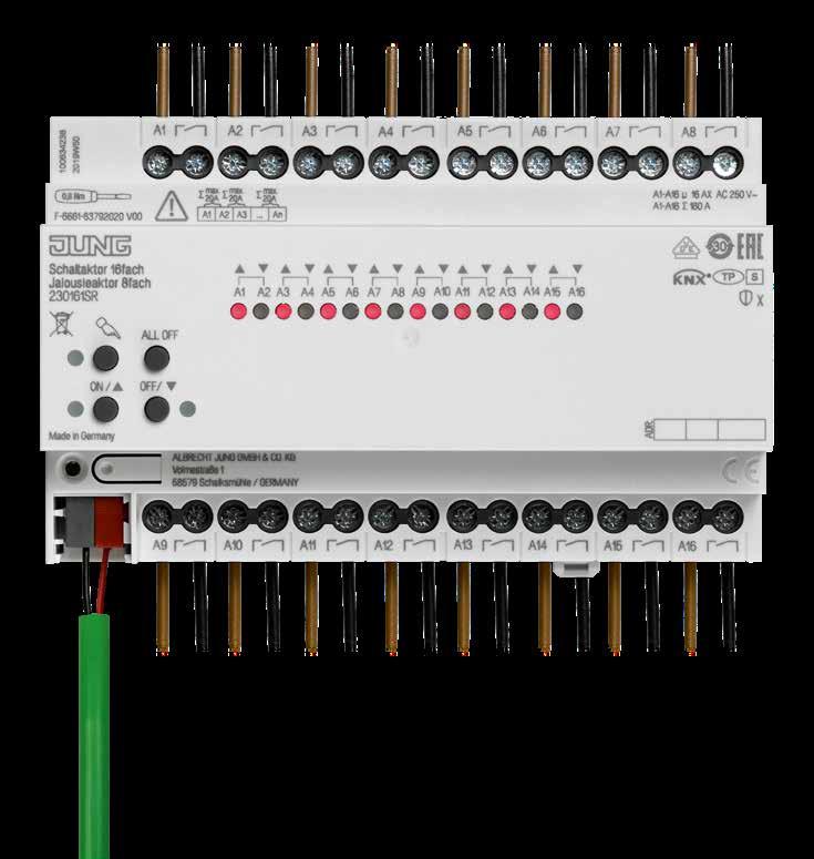 KNX switch actuator, 6-gang / KNX blind actuator, 3-gang
KNX switch actuator, 16-gang/ KNX blind actuator, 8-gang
KNX switch actuator, 6-gang / KNX blind actuator, 3-gang
KNX switch actuator, 16-gang/ KNX blind actuator, 8-gang
4 5 5 2 3
KNX switch actuator 24-gang / KNX blind actuator 12-gang
SWITCH ACTUATOR, 16-GANG KNX BLIND ACTUATOR, 8-GANG
172 ACTUATORS/COMBINATION DEVICES ACTUATORS/COMBINATION DEVICES 173
The new KNX LED Universal dimming actuator, 4-gang The advantages at a glance
The width of the dimming actuator is only 4 TE. This effectively saves space in the distributor.
The parametrisation is much more intuitive with the new actuator generation.
Optimum lighting according to requirements and occasion significantly enhances comfort in a smart building. The JUNG KNX LED Universal dimming actuator, 4-gang, enables reliable dimming of energy-saving light sources. It is also future-proof, works with KNX Data Secure and effectively encrypts all KNX telegrams.
1 W
Logics can be set up decentrally and without a linking device.
Thanks to the reduced minimum load, users can choose from a wide range of compatible and dimmable luminaires.
The JUNG KNX dimming actuator is impressive due to its high functionality in a compact design. The dimming actuator has eight logics, converters, comparators as well as filter and time functions. It also has optimised and adjustable dimming characteristics in the time and value range. However, with only 4 TE, it is only half as wide as its predecessors. This results in clear cost advantages. Thanks to its
update capability, the dimming actuator is future-proof. If a new firmware version is available, installers can install this via the JUNG ETS Service App. Communication on the twisted pair cable is secure thanks to KNX Data Secure and transmissions are protected against manipulation. With the dimming actuator, JUNG creates the best conditions for individual and safe lighting scenes.
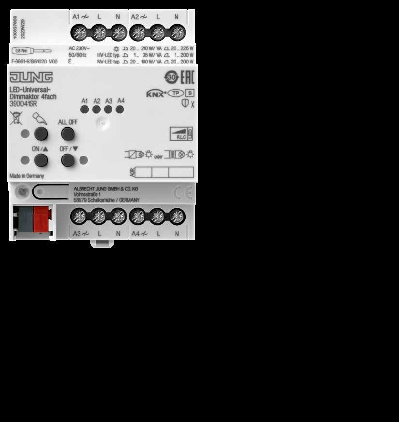 KNX LED UNIVERSAL DIMMING ACTUATOR, 4-GANG
INTEGRATED LOGIC FUNCTIONS MINIMUM LOAD FOR HV LED = 1 W
REDUCED WIDTH ETS 5 OPTIMISED DATABASE
KNX LED UNIVERSAL DIMMING ACTUATOR, 4-GANG
INTEGRATED LOGIC FUNCTIONS MINIMUM LOAD FOR HV LED = 1 W
REDUCED WIDTH ETS 5 OPTIMISED DATABASE
ACTUATORS/COMBINATION DEVICES 175 174 ACTUATORS/COMBINATION DEVICES
ETS
KNX Actuators
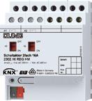
Ref.-no.
KNX switch actuator, 2-gang
Rail mounting device, 4 rail units
2 NO contacts with manual mechanical operation and status indicator
ETS product family: Output
Product type: Binary output
Intended use
• Switching of 110 ... 230 V AC or 24 V AC/DC electrical loads with floating contacts
• Mounting on DIN rail according to EN 60715 in distribution boxes
Product characteristics
• Manual switching of the relays is independent of the bus
• Operation as NO or NC contacts
• Logic operation and forcing function
• Switching feedback (bus operation only)
• Switch position display
• Central switching function with collective feedback
• Disabling function for each channel
• Time functions: switch-on delay, switch-off delay, staircase lighting timer with pre-warning function
• Integration into light scenes
• Operating hours counter, configurable via bus
• Input monitoring for cyclical updating with safety circuit
• No additional power supply necessary
176
2302.16 REGHM
Technical data
KNX medium: TP 256
Rated voltage KNX: DC 21 ... 32 V SELV
Connection, KNX: terminal
Power consumption KNX: typical 150 mW
Power loss: max. 2 W
Ambient temperature: −5 ... +45 °C
Storage/transport temperature: −25 ... +70 °C
Mounting width: 72 mm (4 rail units)
Connection, outputs
Connection mode: screw terminals single wire: 1 x 0.5 ... 4 mm2 stranded without ferrule: 1 x 0.5 ... 4 mm2 stranded with ferrule: 1 x 0.5 ... 2.5 mm2
Switching outputs
Contact type: floating relay contacts (μ contact)
Switching voltage AC: AC 250 / 400 V
Switching current 230 V AC1: 16 A
Switching current 230 V AC3: 10 A
Switching current 400 V AC1: 10 A
Switching current 400 V AC3: 6 A
Fluorescent lamps: 10 AX
Ohmic load: 3680 W
Capacitive load: 10 A / 140 µF
Switching voltage DC: DC 12 ... 24 V
Switching current DC: 16 A
Min. switching current: 100 mA
Switch-on current 150 µs: 400 A
Switch-on current 600 µs: 200 A
Lamp loads
Incandescent lamps: 2500 W
HV halogen lamps: 2500 W
LV halogen lamps with inductive transformers: 1200 VA
electronic transformers: 1500 W
Fluorescent lamps T5/T8
non-compensated: 2500 W parallel compensated: 1300 W / 140 µF lead-lag circuit: 2300 W / 140 µF
Compact fluorescent lamps non-compensated: 2500 W parallel compensated: 1300 W / 140 µF
Mercury vapour lamps non-compensated: 2000 W parallel compensated: 2000 W / 140 µF
Approvals: VDE
KNX Actuators
177
KNX Actuators
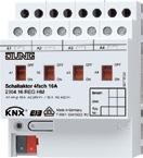
Ref.-no.
KNX switch actuator, 4-gang
Rail mounting device, 4 rail units
4 NO contacts with manual mechanical operation and status indicator
ETS product family: Output
Product type: Binary output
Intended use
• Switching of 110 ... 230 V AC or 24 V AC/DC electrical loads with floating contacts
• Mounting on DIN rail according to EN 60715 in distribution boxes
Product characteristics
• Manual switching of the relays is independent of the bus
• Operation as NO or NC contacts
• Logic operation and forcing function
• Switching feedback (bus operation only)
• Switch position display
• Central switching function with collective feedback
• Disabling function for each channel
• Time functions: switch-on delay, switch-off delay, staircase lighting timer with pre-warning function
• Integration into light scenes
• Operating hours counter, configurable via bus
• Input monitoring for cyclical updating with safety circuit
• No additional power supply necessary
178
2304.16 REGHM
Technical data
KNX medium: TP 256
Rated voltage KNX: DC 21 ... 32 V SELV
Connection, KNX: terminal
Power consumption KNX: typical 150 mW
Power loss: max. 4 W
Ambient temperature: −5 ... +45 °C
Storage/transport temperature: −25 ... +70 °C
Mounting width: 72 mm (4 rail units)
Connection, outputs
Connection mode: screw terminals single wire: 1 x 0.5 ... 4 mm2 stranded without ferrule: 1 x 0.5 ... 4 mm2 stranded with ferrule: 1 x 0.5 ... 2.5 mm2
Switching outputs
Contact type: floating relay contacts (μ contact)
Switching voltage AC: AC 250 / 400 V
Switching current 230 V AC1: 16 A
Switching current 230 V AC3: 10 A
Switching current 400 V AC1: 10 A
Switching current 400 V AC3: 6 A
Fluorescent lamps: 10 AX
Ohmic load: 3680 W
Capacitive load: 10 A / 140 µF
Switching voltage DC: DC 12 ... 24 V
Switching current DC: 16 A
Min. switching current: 100 mA
Switch-on current 150 µs: 400 A
Switch-on current 600 µs: 200 A
Lamp loads
Incandescent lamps: 2500 W
HV halogen lamps: 2500 W
LV halogen lamps with inductive transformers: 1200 VA
electronic transformers: 1500 W
Fluorescent lamps T5/T8
non-compensated: 2500 W parallel compensated: 1300 W / 140 µF lead-lag circuit: 2300 W / 140 µF
Compact fluorescent lamps non-compensated: 2500 W parallel compensated: 1300 W / 140 µF
Mercury vapour lamps non-compensated: 2000 W parallel compensated: 2000 W / 140 µF
Approvals: VDE
KNX Actuators
179
KNX Actuators
Ref.-no.
KNX switch actuator, 8-gang
Rail mounting device, 8 rail units
8 NO contacts with manual mechanical operation and status indicator
Only with the ETS 3.0d version or later versions the full functionality will be available.
ETS product family: Output
Product type: Binary output
Intended use
• Switching of 110 ... 230 V AC or 24 V AC/DC electrical loads with floating contacts
• Mounting on DIN rail according to EN 60715 in distribution boxes
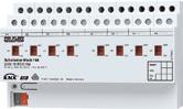
Product characteristics
• Manual switching of the relays is independent of the bus
• Operation as NO or NC contacts
• Logic operation and forcing function
• Switching feedback (bus operation only)
• Switch position display
• Central switching function with collective feedback
• Disabling function for each channel
• Time functions: switch-on delay, switch-off delay, staircase lighting timer with pre-warning function
• Integration into light scenes
• Operating hours counter, configurable via bus
• Input monitoring for cyclical updating with safety circuit
• No additional power supply necessary
180
2308.16 REGHM
Technical data
KNX medium: TP 256
Rated voltage KNX: DC 21 ... 32 V SELV
Connection, KNX: terminal
Power consumption KNX: typical 150 mW
Power loss: max. 8 W
Ambient temperature: −5 ... +45 °C
Storage/transport temperature: −25 ... +70 °C
Mounting width: 144 mm (8 rail units)
Connection, outputs
Connection mode: screw terminals single wire: 1 x 0.5 ... 4 mm2 stranded without ferrule: 1 x 0.5 ... 4 mm2 stranded with ferrule: 1 x 0.5 ... 2.5 mm2
Switching outputs
Contact type: floating relay contacts (μ contact)
Switching voltage AC: AC 250 / 400 V
Switching current 230 V AC1: 16 A
Switching current 230 V AC3: 10 A
Switching current 400 V AC1: 10 A
Switching current 400 V AC3: 6 A
Fluorescent lamps: 10 AX
Ohmic load: 3680 W
Capacitive load: 10 A / 140 µF
Switching voltage DC: DC 12 ... 24 V
Switching current DC: 16 A
Min. switching current: 100 mA
Switch-on current 150 µs: 400 A
Switch-on current 600 µs: 200 A
Lamp loads
Incandescent lamps: 2500 W
HV halogen lamps: 2500 W
LV halogen lamps with inductive transformers: 1200 VA
electronic transformers: 1500 W
Fluorescent lamps T5/T8
non-compensated: 2500 W parallel compensated: 1300 W / 140 µF lead-lag circuit: 2300 W / 140 µF
Compact fluorescent lamps non-compensated: 2500 W parallel compensated: 1300 W / 140 µF
Mercury vapour lamps non-compensated: 2000 W parallel compensated: 2000 W / 140 µF
Approvals: VDE
KNX Actuators
181
KNX Actuators
Ref.-no.
KNX switch actuator with C-load, 4-gang with current detection
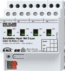
Rail mounting device, 4 rail units
4 NO contacts with manual mechanical operation and status indicator
Only with the ETS 3.0d version or later versions the full functionality will be available.
ETS product family: Output
Product type: Binary output
Intended use
• Switching of 110 ... 230 V AC or 24 V AC/DC electrical loads with floating contacts
• Mounting on DIN rail according to EN 60715 in distribution boxes
Product characteristics
• Manual switching of the relays is independent of the bus
• Operation as NO or NC contacts
• Logic operation and forcing function
• Switching feedback (bus operation only)
• Switch position display
• Central switching function with collective feedback
• Disabling function for each channel
• Time functions: switch-on delay, switch-off delay, staircase lighting timer with pre-warning function
• Integration into light scenes
• Operating hours counter, configurable via bus
• Input monitoring for cyclical updating with safety circuit
• No additional power supply necessary
• Current detection: measurement of the load current for each output
• Monitoring of threshold values for load monitoring, e.g. for reporting load drop-out
• Switching of capacitive loads and the resulting high switch-on currents
182
2304.16 REGCHM
Technical data
KNX medium: TP 256
Rated voltage KNX: DC 21 ... 32 V SELV
Connection, KNX: terminal
Power consumption KNX: typical 240 mW
Power loss: max. 4 W
Ambient temperature: −5 ... +45 °C
Storage/transport temperature: −25 ... +70 °C
Mounting width: 72 mm (4 rail units)
Connection, outputs
Connection mode: screw terminals
single wire: 1 x 0.5 ... 4 mm2 stranded without ferrule: 1 x 0.5 ... 4 mm2 stranded with ferrule: 1 x 0.5 ... 2.5 mm2
Current detection (sine)
Mains frequency: 50/60 Hz
Measuring range: 0.25 ... 16 A
Accuracy (≤ 1 A): ±100 mA
Accuracy (> 1 A): ±8 % of curr. val.
Switching outputs
Contact type: floating relay contacts (μ contact)
Switching voltage AC: AC 250 / 400 V
Switching current 230 V AC1: 16 A
Switching current 230 V AC3: 10 A
Switching current 400 V AC1: 10 A
Switching current 400 V AC3: 6 A
Fluorescent lamps: 16 AX Ohmic load: 3680 W
Capacitive load: 16 A / 200 µF
Switching voltage DC: DC 12 ... 24 V
Switching current DC: 16 A
Min. switching current: 100 mA
Switch-on current 150 µs: 600 A Switch-on current 600 µs: 300 A Lamp loads
Incandescent lamps:
KNX Actuators
Fluorescent lamps T5/T8
3680 W parallel compensated: 2500 W / 200 µF lead-lag circuit: 3680 W / 200 µF
Compact fluorescent lamps non-compensated: 3680 W
parallel compensated: 2500 W / 200 µF
Mercury vapour lamps
non-compensated: 3680 W
parallel compensated: 3680 W / 200 µF
Approvals: VDE
183
3680
LV
W HV halogen lamps: 3680 W
halogen lamps with inductive transformers: 2000 VA electronic transformers: 2500 W
non-compensated:
KNX Actuators
Ref.-no.
KNX switch actuator with C-load, 8-gang with current detection
Rail mounting device, 8 rail units
8 NO contacts with manual mechanical operation and status indicator
Only with the ETS 3.0d version or later versions the full functionality will be available.
ETS product family: Output
Product type: Binary output
Intended use
• Switching of 110 ... 230 V AC or 24 V AC/DC electrical loads with floating contacts
• Mounting on DIN rail according to EN 60715 in distribution boxes
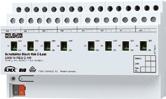
Product characteristics
• Manual switching of the relays is independent of the bus
• Operation as NO or NC contacts
• Logic operation and forcing function
• Switching feedback (bus operation only)
• Switch position display
• Central switching function with collective feedback
• Disabling function for each channel
• Time functions: switch-on delay, switch-off delay, staircase lighting timer with pre-warning function
• Integration into light scenes
• Operating hours counter, configurable via bus
• Input monitoring for cyclical updating with safety circuit
• No additional power supply necessary
• Current detection: measurement of the load current for each output
• Monitoring of threshold values for load monitoring, e.g. for reporting load drop-out
• Switching of capacitive loads and the resulting high switch-on currents
184
2308.16 REGCHM
Technical data
KNX medium: TP 256
Rated voltage KNX: DC 21 ... 32 V SELV
Connection, KNX: terminal
Power consumption KNX: typical 240 mW
Power loss: max. 8 W
Ambient temperature: −5 ... +45 °C
Storage/transport temperature: −25 ... +70 °C
Mounting width: 144 mm (8 rail units)
Connection, outputs
Connection mode: screw terminals
single wire: 1 x 0.5 ... 4 mm2 stranded without ferrule: 1 x 0.5 ... 4 mm2 stranded with ferrule: 1 x 0.5 ... 2.5 mm2
Current detection (sine)
Mains frequency: 50/60 Hz
Measuring range: 0.25 ... 16 A
Accuracy (≤ 1 A): ±100 mA
Accuracy (> 1 A): ±8 % of curr. val.
Switching outputs
Contact type: floating relay contacts (μ contact)
Switching voltage AC: AC 250 / 400 V
Switching current 230 V AC1: 16 A
Switching current 230 V AC3: 10 A
Switching current 400 V AC1: 10 A
Switching current 400 V AC3: 6 A
Fluorescent lamps: 16 AX Ohmic load: 3680 W
Capacitive load: 16 A / 200 µF
Switching voltage DC: DC 12 ... 24 V
Switching current DC: 16 A
Min. switching current: 100 mA
Switch-on current 150 µs: 600 A Switch-on current 600 µs: 300 A Lamp loads
Incandescent lamps:
KNX Actuators
Fluorescent lamps T5/T8
3680 W parallel compensated: 2500 W / 200 µF lead-lag circuit: 3680 W / 200 µF
Compact fluorescent lamps non-compensated: 3680 W
parallel compensated: 2500 W / 200 µF
Mercury vapour lamps
non-compensated: 3680 W
parallel compensated: 3680 W / 200 µF
Approvals: VDE
185
3680
LV
W HV halogen lamps: 3680 W
halogen lamps with inductive transformers: 2000 VA electronic transformers: 2500 W
non-compensated:
KNX Actuators
Ref.-no.
KNX switch actuator 6-gang
KNX blinds actuator 3-gang
Rail mounting device, 4 rail units with manual electronic operation and LED status indication
Project design and commissioning with ETS5 or a more recent version.
ETS product family: Output
Product type: Binary output
Intended use
• Switching of electrical loads with floating contacts
• Switching of electrically-driven blinds, shutters, awnings and similar hangings
• Mounting on DIN rail according to EN 60715 in distribution boxes
Product characteristics
• Outputs can be operated manually, construction site mode
• Feedback in manual mode and in bus mode
• Disabling of individual outputs manually or via bus
• Central functions
• Cyclical monitoring
• KNX Data Secure compatible with ETS 5.7.3 or higher
• Can be updated with the ETS Service App
Characteristics switching operation
• Operation as NO or NC contacts
• Feedback function
• Logic operation and forcing function
• Central switching function with collective feedback
• Time functions: switch-on delay, switch-off delay, staircase lighting timer with pre-warning function
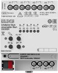
• Scene function
• Operating hours counter
Characteristics blinds operation
• Suitable for 230 V AC motors
• Operation modes ‘Blind with slats’, ‘Shutter/awning’, ‘Ventilation flap/skylight’
• Blind/shutter position directly controllable
• Slat position directly controllable
• Feedback of movement status, blind/shutter position and slat position
• Cyclical feedback during movement
• Forced position through higher-level controller
• Safety function: rain alarm, frost alarm, 3 independent wind alarms
• Sun protection function with auto Heating/Cooling
• Scene function
The total current of two adjacent outputs must not exceed 20 A.
186
N 23006 1S R
Technical data
Ambient temperature: −5 ... +45 °C
Storage/transport temperature: −25 ... +70 °C
KNX KNX medium: TP 256
Rated voltage KNX: DC 21 ... 32 V SELV
Current consumption KNX: 4 ... 18 mA
Outputs
Switching voltage: AC 250 V ~
Switching current AC1 (cos ϕ > 0.8): 16 A
Fluorescent lamps: 16 AX
Current carrying capacity
Neighbouring outputs: Σ 20 A
Loads per output
Ohmic load: 3000 W
Capacitive load: 16 A / 140 µF
Motors: 1380 VA
Switch-on current 200 µs: max. 800 A
Switch-on current 20 ms: max. 165 A
Lamp loads 230 V
Incandescent lamps: 3000 W
HV halogen lamps: 2500 W
HV LED lamps: max. 400 W
LV halogen lamps with electronic transformers: 1500 W
inductive transformers: 1200 VA
Fluorescent lamps T5/T8
W
KNX Actuators
/ 140 µF
/ 140 µF Mercury vapour lamps
compensated:
W
compensated: 1160 W / 140 µF
Mounting width: 72 mm (4 rail units)
Connection, power supply and load
Connection mode: screw terminals single wire:
x 0.5 ... 4 mm2 stranded without ferrule:
x 0.5 ... 4 mm2 stranded with ferrule:
x 0.5 ... 2.5 mm2
KNX: KNX bus connection block
187
1000
parallel
1160 W
lead-lag
2300 W
parallel
non-compensated:
compensated:
circuit:
/ 140 µF Compact fluorescent lamps non-compensated: 1000 W
1160 W
non-compensated: 1000
parallel
1
1
1
KNX Actuators
Ref.-no.
KNX switch actuator 16-gang
KNX blinds actuator 8-gang
Rail mounting device, 8 rail units with manual electronic operation and LED status indication Project design and commissioning with ETS5 or a more recent version.
ETS product family: Output
Product type: Binary output
Intended use
• Switching of electrical loads with floating contacts
N
• Switching of electrically-driven blinds, shutters, awnings and similar hangings
• Mounting on DIN rail according to EN 60715 in distribution boxes
Product characteristics
• Outputs can be operated manually, construction site mode
• Feedback in manual mode and in bus mode
• Disabling of individual outputs manually or via bus
• Central functions
• Cyclical monitoring
• KNX Data Secure compatible with ETS 5.7.3 or higher
• Can be updated with the ETS Service App
Characteristics switching operation
• Operation as NO or NC contacts
• Feedback function
• Logic operation and forcing function
• Central switching function with collective feedback
• Time functions: switch-on delay, switch-off delay, staircase lighting timer with pre-warning function
• Scene function
• Operating hours counter
Characteristics blinds operation
• Suitable for 230 V AC motors
• Operation modes ‘Blind with slats’, ‘Shutter/awning’, ‘Ventilation flap/skylight’
• Blind/shutter position directly controllable
• Slat position directly controllable
• Feedback of movement status, blind/shutter position and slat position
• Cyclical feedback during movement
• Forced position through higher-level controller
• Safety function: rain alarm, frost alarm, 3 independent wind alarms
• Sun protection function with auto Heating/Cooling
• Scene function
The total current of two adjacent outputs must not exceed 20 A.
188
23016 1S R
Technical data
Ambient temperature: −5 ... +45 °C
Storage/transport temperature: −25 ... +70 °C
KNX KNX medium: TP 256
Rated voltage KNX: DC 21 ... 32 V SELV
Current consumption KNX: 4 ... 18 mA
Outputs
Switching voltage: AC 250 V ~
Switching current AC1 (cos ϕ > 0.8): 16 A
Fluorescent lamps: 16 AX
Current carrying capacity
Neighbouring outputs: Σ 20 A
Loads per output
Ohmic load: 3000 W
Capacitive load: 16 A / 140 µF
Motors: 1380 VA
Switch-on current 200 µs: max. 800 A
Switch-on current 20 ms: max. 165 A
Lamp loads 230 V
Incandescent lamps: 3000 W
HV halogen lamps: 2500 W
HV LED lamps: max. 400 W
LV halogen lamps with electronic transformers: 1500 W
inductive transformers: 1200 VA
Fluorescent lamps T5/T8
/ 140 µF
KNX Actuators
/ 140 µF Mercury vapour lamps
/ 140 µF
Mounting width: 144 mm (8 rail units)
Connection, power supply and load
Connection mode: screw terminals single wire:
x 0.5 ... 4 mm2 stranded without ferrule:
x 0.5 ... 4 mm2 stranded with ferrule:
x 0.5 ... 2.5 mm2
KNX: KNX bus connection block
189
1000
parallel
1160 W
lead-lag
2300 W
non-compensated: 1000
parallel
1160 W
non-compensated:
W
compensated:
circuit:
/ 140 µF Compact fluorescent lamps
W
compensated:
non-compensated: 1000 W parallel compensated: 1160 W
1
1
1
KNX Actuators
Ref.-no.
KNX switch actuator 24-gang
KNX blinds actuator 12-gang
Rail mounting device, 12 rail units with manual electronic operation and LED status indication
Project design and commissioning with ETS5 or a more recent version.
ETS product family: Output
Product type: Binary output
Intended use
• Switching of electrical loads with floating contacts
N
• Switching of electrically-driven blinds, shutters, awnings and similar hangings
• Mounting on DIN rail according to EN 60715 in distribution boxes
Product characteristics
• Outputs can be operated manually, construction site mode
• Feedback in manual mode and in bus mode
• Disabling of individual outputs manually or via bus
• Central functions
• Cyclical monitoring
• KNX Data Secure compatible with ETS 5.7.3 or higher
• Can be updated with the ETS Service App
Characteristics switching operation
• Operation as NO or NC contacts
• Feedback function
• Logic operation and forcing function
• Central switching function with collective feedback
• Time functions: switch-on delay, switch-off delay, staircase lighting timer with pre-warning function
• Scene function
• Operating hours counter
Characteristics blinds operation
• Suitable for 230 V AC motors
• Operation modes ‘Blind with slats’, ‘Shutter/awning’, ‘Ventilation flap/skylight’
• Blind/shutter position directly controllable
• Slat position directly controllable
• Feedback of movement status, blind/shutter position and slat position
• Cyclical feedback during movement
• Forced position through higher-level controller
• Safety function: rain alarm, frost alarm, 3 independent wind alarms
• Sun protection function with auto Heating/Cooling
• Scene function
The total current of two adjacent outputs must not exceed 20 A.
190
23024 1S R
Technical data
Ambient temperature: −5 ... +45 °C
Storage/transport temperature: −25 ... +70 °C
KNX KNX medium: TP 256
Rated voltage KNX: DC 21 ... 32 V SELV
Current consumption KNX: 4 ... 24 mA
Outputs
Switching voltage: AC 250 V ~
Switching current AC1 (cos ϕ > 0.8): 16 A
Fluorescent lamps: 16 AX
Current carrying capacity
Neighbouring outputs: Σ 20 A
Loads per output
Ohmic load: 3000 W
Capacitive load: 16 A / 140 µF
Motors: 1380 VA
Switch-on current 200 µs: max. 800 A
Switch-on current 20 ms: max. 165 A
Lamp loads 230 V
Incandescent lamps: 3000 W
HV halogen lamps: 2500 W
HV LED lamps: max. 400 W
LV halogen lamps with electronic transformers: 1500 W
inductive transformers: 1200 VA
Fluorescent lamps T5/T8
W
KNX Actuators
/ 140 µF
/ 140 µF Mercury vapour lamps
/ 140 µF
Mounting width: 216 mm (12 rail units)
Connection, power supply and load
Connection mode: screw terminals single wire:
x 0.5 ... 4 mm2 stranded without ferrule:
x 0.5 ... 4 mm2 stranded with ferrule:
x 0.5 ... 2.5 mm2
KNX: KNX bus connection block
191
1000
parallel
1160 W
lead-lag
2300 W
1000
parallel
1160 W
non-compensated:
compensated:
circuit:
/ 140 µF Compact fluorescent lamps non-compensated:
W
compensated:
non-compensated: 1000 W parallel compensated: 1160 W
1
1
1
KNX Actuators
Ref.-no.
KNX blinds actuator, 4-gang DC 12 – 48 V Rail mounting device, 4 rail units with manual electronic operation and LED status indication Only with the ETS 3.0d version or later versions the full functionality will be available. ETS product family: Shutter Product type: Shutter
Intended use
• Switching of electrically driven blinds, shutters, awnings and similar hangings for AC 110 – 230 V mains voltage or DC 12 – 48 V extra-low voltage.
• Mounting on DIN rail in distribution boxes
Product characteristics
• Suitable for 110 ... 230 V AC motors and 12 ... 48 V DC motors
• Automatic operation time detection for 230 V motors can be set
• Slat position directly controllable
• Acknowledgement of travelling state and slat position in bus and manual mode
• Scene function
• Top and bottom forced position via higher-level controller
• Sun protection function
Technical data
KNX medium: TP 256
Outputs: 4 independent channels for one blind/shutter motor each
Contact type: floating NO contact
Switching voltage DC: DC 12 ... 48 V
Breaking capacity DC 12 V: 6 A
Breaking capacity DC 24 V: 6 A
Breaking capacity DC 48 V: 3 A
Min. switching current DC: 100 mA
Connection
Connection mode: screw terminals
single wire: 1 x 0.5 ... 4 mm2
stranded without ferrule: 1 x 0.5 ... 4 mm2
stranded with ferrule: 1 x 0.5 ... 2.5 mm2
192
2424 REGHE
Ref.-no.
KNX blinds actuator, 2-gang AC 110 – 230 V, 1-gang DC 12 – 48 V Rail mounting device, 4 rail units with manual electronic operation and LED status indication Only with the ETS 3.0d version or later versions the full functionality will be available. ETS product family: Shutter
Product type: Shutter
Intended use
• Switching of electrically driven blinds, shutters, awnings and similar hangings for AC 110 – 230 V mains voltage or DC 12 – 48 V extra-low voltage.
• Mounting on DIN rail in distribution boxes
Product characteristics
• Suitable for 110 ... 230 V AC motors and 12 ... 48 V DC motors
• Automatic operation time detection for 230 V motors can be set
• Slat position directly controllable
• Acknowledgement of travelling state and slat position in bus and manual mode
• Scene function
• Top and bottom forced position via higher-level controller
• Sun protection function
Technical data
KNX medium: TP 256
Outputs: 2 channels AC 110 ... 230 V, 1 channel DC 12 ... 48 V
Power supply mains: AC 110 V (−10 %) ... 240 V (+10 %)
Mains frequency: 50/60 Hz Connection Connection mode: screw terminals single wire: 1 x 0.5 ... 4 mm2
0.5 ... 4 mm2
x 0.5 ... 2.5 mm2
193 KNX
Actuators
2502 REGHE
stranded
1
Breaking capacity AC1: 6
Switching current DC 12/24 V: 6 A Switching current DC 48 V: 3 A Max. blind/shutter running time: 20 min Power loss: max. 4.5 W Ambient temperature: −5 ... +45 °C Storing temperature: −25 ... +70 °C Approvals: VDE
stranded without ferrule: 1 x
with ferrule:
A (230 V)
KNX Actuators
Ref.-no.
KNX blinds actuator, 4-gang AC 110 – 230 V, 2-gang DC 12 – 48 V
Rail mounting device, 4 rail units with manual electronic operation and LED status indication Only with the ETS 3.0d version or later versions the full functionality will be available.
ETS product family: Shutter
Product type: Shutter
Intended use
• Switching of electrically driven blinds, shutters, awnings and similar hangings for AC 110 – 230 V mains voltage or DC 12 – 48 V extra-low voltage.
• Mounting on DIN rail in distribution boxes
Product characteristics
• Suitable for 110 ... 230 V AC motors and 12 ... 48 V DC motors
• Automatic operation time detection for 230 V motors can be set
• Slat position directly controllable
• Acknowledgement of travelling state and slat position in bus and manual mode
• Scene function
• Top and bottom forced position via higher-level controller
• Sun protection function
Technical data
KNX medium: TP 256
2504 REGHE
Outputs: 4 channels AC 110 ... 230 V, 2 channels DC 12 ... 48 V
Power supply mains: AC 110 V (−10 %) ... 240 V (+10 %)
Mains frequency: 50/60 Hz
Connection
Connection mode: screw terminals
single wire: 1 x 0.5 ... 4 mm2
stranded without ferrule: 1 x 0.5 ... 4 mm2
stranded with ferrule: 1 x 0.5 ... 2.5 mm2
Breaking capacity AC1: 6 A (230 V)
Switching current DC 12/24 V: 6 A
Switching current DC 48 V: 3 A
Max. blind/shutter running time: 20 min
Power loss: max. 4.5 W
Ambient temperature: −5 ... +45 °C
Storing temperature: −25 ... +70 °C
Approvals: VDE
194
Ref.-no.
KNX blinds actuator, 4-gang AC 110 – 230 V, 2-gang DC 12 – 48 V Rail mounting device, 4 rail units with manual electronic operation and LED status indication
Blind/shutter correction for lower end position (e.g. for ventilation position for roller blinds) Only with the ETS 3.0d version or later versions the full functionality will be available.
ETS product family: Shutter
Product type: Shutter
Intended use
• Switching of electrically driven blinds, shutters, awnings and similar hangings for AC 110 – 230 V mains voltage or DC 12 – 48 V extra-low voltage.
• Mounting on DIN rail in distribution boxes
Product characteristics
• Suitable for 110 ... 230 V AC motors and 12 ... 48 V DC motors
• Automatic operation time detection for 230 V motors can be set
• Slat position directly controllable
• Acknowledgement of travelling state and slat position in bus and manual mode
• Scene function
• Top and bottom forced position via higher-level controller
• Sun protection function
Technical data
KNX medium: TP 256
Outputs: 4 channels AC 110 ... 230 V, 2 channels DC 12 ... 48 V
Power supply mains: AC 110 V (−10 %) ... 240 V (+10 %)
Mains frequency: 50/60 Hz
195 KNX
Actuators
2514 REGHE
Connection Connection mode: screw terminals single wire: 1 x 0.5 ... 4 mm2 stranded without ferrule: 1 x 0.5 ... 4 mm2 stranded with ferrule: 1 x 0.5 ... 2.5 mm2 Breaking capacity AC1: 6 A (230 V) Switching current DC 12/24 V: 6 A Switching current DC 48 V: 3 A Max. blind/shutter running time: 20 min Power loss: max. 4.5 W Ambient temperature: −5 ... +45 °C Storing temperature: −25 ... +70 °C
Approvals: VDE
KNX Actuators
Ref.-no.
KNX blinds actuator, 8-gang AC 110 – 230 V, 4-gang DC 12 – 48 V
Rail mounting device, 8 rail units with manual electronic operation and LED status indication Only with the ETS 3.0d version or later versions the full functionality will be available.
ETS product family: Shutter
Product type: Shutter
Intended use
• Switching of electrically driven blinds, shutters, awnings and similar hangings for AC 110 – 230 V mains voltage or DC 12 – 48 V extra-low voltage.
• Mounting on DIN rail in distribution boxes
Product characteristics
• Suitable for 110 ... 230 V AC motors and 12 ... 48 V DC motors
• Automatic operation time detection for 230 V motors can be set
• Slat position directly controllable
• Acknowledgement of travelling state and slat position in bus and manual mode
• Scene function
• Top and bottom forced position via higher-level controller
• Sun protection function
Technical data
KNX medium: TP 256
2508 REGHE
Outputs: 8 channels AC 110 ... 230 V, 4 channels DC 12 ... 48 V
Power supply mains: AC 110 V (−10 %) ... 240 V (+10 %)
Mains frequency: 50/60 Hz
Connection
Connection mode: screw terminals
single wire: 1 x 0.5 ... 4 mm2 stranded without ferrule: 1 x 0.5 ... 4 mm2 stranded with ferrule: 1 x 0.5 ... 2.5 mm2
Breaking capacity AC1: 6 A (230 V)
Switching current DC 12/24 V: 6 A
Switching current DC 48 V: 3 A
Max. blind/shutter running time: 20 min
Power loss: max. 6 W
Ambient temperature: −5 ... +45 °C
Storing temperature: −25 ... +70 °C
Approvals: VDE
196
KNX shutter actuator 4-gang AC 110 – 230 V
Rail mounting device, 4 rail units with manual electronic operation and LED status indication
ETS product family: Shutter
Product type: Shutter
Product characteristics
• Outputs can be operated manually, construction site mode
• Blind/shutter position directly controllable
• Acknowledgement of the blind/shutter position in bus and manual mode
• Safety function: rain alarm, frost alarm, 3 independent wind alarms
• Integration into the temperature management of the building
• Disabling of individual outputs manually or via bus
• No central function
• No end position detection
• No feedback for drive movement
• No sun protection
• No scene function
• No forced position
• No fabric-stretching
Technical data
KNX medium: TP 256
Rated voltage: AC 110 V (−10 %) ... 240 V (+10 %)
Mains frequency: 50/60 Hz
Switching voltage: AC 250 V ~
Storage/transport
197
Ref.-no.
KNX Actuators
2504 REGHER
Switching current AC 250 V: 6
Switching current DC 12/24 V: 6 A Switching current DC 48 V: 3 A Connection, power supply and load Connection mode: screw terminals single wire: 1 x 0.5 ... 4 mm2 stranded without ferrule: 1 x 0.5 ... 4 mm2 stranded with ferrule: 1 x 0.5 ... 2.5 mm2 Max. blind/shutter running time: 20
A
min Mounting width: 72 mm (4 rail units) Ambient temperature: −5 ... +45 °C
Connection,
Approvals:
temperature: −25 ... +70 °C Power loss: max. 4.5 W Rated voltage KNX: DC 21 ... 32 V SELV Power consumption KNX: typical 150 mW
KNX: terminal
VDE
KNX Actuators
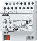
Ref.-no.
KNX LED universal dimming actuator / speed regulator, 1-gang 1 x 500 W, HV LED lamps typ. 3 ... 100 W
Rail mounting device, 4 rail units
ETS product family: Illumination
Product type: Dimmer
Intended use
• Switching and dimming of incandescent lamps, HV halogen lamps, dimmable HV LED lamps, dimmable compact fluorescent lamps, dimmable inductive transformers with LV halogen or LV LED lamps, dimmable electronic transformers with LV halogen or LV LED lamps
• Mounting on DIN rail according to EN 60715 in distribution boxes
• Speed controller for regulating the speed of single-phase motors e.g. induction motors, shaded pole motors or universal motors
Product characteristics
• Automatic or manual setting of the dimming principle suitable for the load
• Protected against no-load, short-circuit and overheating
• Signal in the event of a short-circuit
• Outputs can be operated manually
• Feedback of the switching position and the dimming value
• Parameterisable switch-on and dimming behaviour
• Time functions: switch-on delay, switch-off delay, staircase lighting timer with pre-warning function
• Light scene operation
• Disabling of individual outputs manually or via bus
• Status indication of the outputs via LED
• Operating hours counter
• Mains failure longer than approx. 5 seconds leads to switch-off of the dimmer actuator. Depending on the parameter setting, the connected load is calibrated after resumption of power supply.
• Power extension possible by means of power boosters (ref.-no. ULZ 1755 REG)
• Optional accessory: compensation module LED, ref.-no.: KM LED 230 U
198
3901 REGHE
Technical data
KNX medium: TP 256
Rated voltage: AC 110 ... 230 V ~, 50/60 Hz
Power loss: max. 4 W
Stand-by power: max. 0.5 W
Ambient temperature: −5 ... +45 °C
Storage/transport temperature: −25 ... +70 °C
Contact type: ε, MOSFET
Motor loads
Motor switching current: 2.3 A
Lamp loads
Connected load, 230 V per output
Incandescent lamps: 20 ... 500 W
HV halogen lamps: 20 ... 500 W
Inductive transformers: 20 ... 500 VA
Inductive transformers with LV LED: 20 ... 100 VA
Electronic transformers: 20 ... 500 W
Electronic transformers with LV LED: 20 ... 100 W
Dimmable HV LED lamps: typical 3 ... 100 W
Dimmable compact fluorescent lamps: typical 3 ... 100 W
With setting "LED trailing edge phase control" the max. connection power for HV LED lamps and electronic transformers with LV LED doubles.
Ohmic-inductive: 20 ... 500 VA
Ohmic-capacitive: 20 ... 500 W
Capacitive-inductive: not permitted
Connected load, 110 V per output
Incandescent lamps: 20 ... 250 W
HV halogen lamps: 20 ... 250 W
Inductive transformers: 20 ... 250 VA
Inductive transformers with LV LED: 20 ... 50 VA
Electronic transformers: 20 ... 250 W
Electronic transformers with LV LED: 20 ... 50 VA
Dimmable HV LED lamps: typical 3 ... 50 W
Dimmable compact fluorescent lamps: typical 3 ... 50 W
With setting "LED trailing edge phase control" the max. connection power for HV LED lamps and electronic transformers with LV LED doubles.
Ohmic-inductive: 20 ... 250 VA
Ohmic-capacitive: 20 ... 250 W
Capacitive-inductive: not permitted
Connection
Connection mode: screw terminals
single wire: 1 x 0.5 ... 4 mm2
stranded without ferrule: 1 x 0.5 ... 4 mm2
stranded with ferrule: 1 x 0.5 ... 2.5 mm2
Mounting width: 72 mm (4 rail units)
Approvals: VDE
199
LE D R,L,C, M
KNX Actuators
KNX Actuators
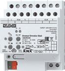
Ref.-no.
KNX LED universal dimming actuator, 2-gang 2 x 300 W, HV LED lamps typ. 2 x 3 ... 60 W
Rail mounting device, 4 rail units
ETS product family: Illumination
Product type: Dimmer
Intended use
• Switching and dimming of incandescent lamps, HV halogen lamps, dimmable HV LED lamps, dimmable compact fluorescent lamps, dimmable inductive transformers with LV halogen or LV LED lamps, dimmable electronic transformers with LV halogen or LV LED lamps
• Mounting on DIN rail according to EN 60715 in distribution boxes
Product characteristics
• Automatic or manual setting of the dimming principle suitable for the load
• Protected against no-load, short-circuit and overheating
• Signal in the event of a short-circuit
• Outputs can be operated manually
• Feedback of the switching position and the dimming value
• Parameterisable switch-on and dimming behaviour
• Time functions: switch-on delay, switch-off delay, staircase lighting timer with pre-warning function
• Light scene operation
• Disabling of individual outputs manually or via bus
• Status indication of the outputs via LED
• Operating hours counter
• Mains failure longer than approx. 5 seconds leads to switch-off of the dimmer actuator. Depending on the parameter setting, the connected load is calibrated after resumption of power supply.
• Power extension possible by means of power boosters (ref.-no. ULZ 1755 REG)
• Optional accessory: compensation module LED, ref.-no.: KM LED 230 U
200
3902 REGHE
Technical data
KNX medium: TP 256
Rated voltage: AC 110 ... 230 V ~, 50/60 Hz
Power loss: max. 4 W
Stand-by power: max. 0.8 W
Ambient temperature: −5 ... +45 °C
Storage/transport temperature: −25 ... +70 °C
Contact type: ε, MOSFET
Lamp loads
Connected load, 230 V per output
Incandescent lamps: 20 ... 300 W
HV halogen lamps: 20 ... 300 W
Inductive transformers: 20 ... 300 VA
Inductive transformers with LV LED: 20 ... 100 VA
Electronic transformers: 20 ... 300 W
Electronic transformers with LV LED: 20 ... 100 W
Dimmable HV LED lamps: typical 3 ... 60 W
Dimmable compact fluorescent lamps: typical 3 ... 60 W
With setting "LED trailing edge phase control" the max. connection power for HV LED lamps and electronic transformers with LV LED doubles.
Ohmic-inductive: 20 ... 300 VA
Ohmic-capacitive: 20 ... 300 W
Capacitive-inductive: not permitted
Connected load, 110 V per output
Incandescent lamps: 20 ... 150 W
HV halogen lamps: 20 ... 150 W
Inductive transformers: 20 ... 150 VA
Inductive transformers with LV LED: 20 ... 50 VA
Electronic transformers: 20 ... 150 W
Electronic transformers with LV LED: 20 ... 50 W
Dimmable HV LED lamps: typical 3 ... 30 W
Dimmable compact fluorescent lamps: typical 3 ... 30 W
With setting "LED trailing edge phase control" the max. connection power for HV LED lamps and electronic transformers with LV LED doubles.
Ohmic-inductive: 20 ... 150 VA
Ohmic-capacitive: 20 ... 150 W
Capacitive-inductive: not permitted
Connection
Connection mode: screw terminals
single wire: 1 x 0.5 ... 4 mm2
stranded without ferrule: 1 x 0.5 ... 4 mm2
stranded with ferrule: 1 x 0.5 ... 2.5 mm2
Mounting width: 72 mm (4 rail units)
Approvals: VDE
201
LE D
KNX Actuators
KNX Actuators
Ref.-no.
KNX LED universal dimming actuator, 4-gang 4 x 225 W, HV LED lamps typ. 4 x 1 ... 35 W (leading edge phase control), 4 x 1 ... 200 W (trailing edge phase control)
1 x 855 W with manual electronic operation and LED status indication Project design and commissioning with ETS5 or a more recent version. Rail mounting device, 4 rail units ETS product family: Illumination
Product type: Dimmer
Intended use
• Switching and dimming of incandescent lamps, HV halogen lamps, dimmable HV LED lamps, dimmable compact fluorescent lamps, dimmable inductive transformers with LV halogen or LV LED lamps, dimmable electronic transformers with LV halogen or LV LED lamps • Mounting on DIN rail according to EN 60715 in distribution boxes
Product characteristics
• Outputs can be operated manually, construction site mode • Feedback in manual mode and in bus mode
• Disabling of individual outputs manually or via bus • Status feedback • KNX Data Secure compatible with ETS 5.7.3 or higher • Can be updated with the ETS Service App Dimming operation characteristic
• Automatic or manual setting of the dimming principle suitable for the load • Protected against no-load, short-circuit and overheating • Signal in the event of a short-circuit, power failure and overload • Feedback of the switching position and the dimming value • Parameterisable switch-on and dimming behaviour • Time functions: switch-on delay, switch-off delay, staircase lighting timer with pre-warning function • Light scene operation • Status indication of the outputs via LED • Operating hours counter • Mains failure longer than approx. 5 seconds leads to switch-off of the dimmer actuator. Depending on the parameter setting, the connected load is calibrated after resumption of power supply.
• Increase in output power possible through parallel switching of multiple outputs
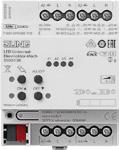
• Power extension possible by means of power boosters (ref.-no. ULZ 1755 REG)
• Optional accessory: compensation module LED, ref.-no.: KM LED 230 U Logic function characteristics
• Logic gates • Transformer (conversion) • Disabling element • Comparator • Limit value switch
Technical data
Rated voltage: AC 110 ... 230 V ~
Mains frequency: 50/60 Hz
Power loss: max. 7 W
Stand-by power: approx. 0.16 W per channel
Ambient temperature: −5 ... +45 °C
Storage/transport temperature: −25 ... +70 °C
Lamp loads
Connected load, 230 V per output
If the maximum connected load is lowered to 110 V, the lamp loads fall by 50 %
Leading edge phase control
Incandescent / HV halogen lamps 20 ... 210 W
Inductive transformers: 20 ... 210 VA
Electronic transformers: 20 ... 210 W
Dimmable LV LED lamps: 20 ... 100 VA
Dimmable HV LED lamps: 1 ... 35 W
Dimmable compact fluorescent lamps: 20 ... 80 W
Trailing edge phase control
Incandescent / HV halogen lamps 20 ... 225 W
Electronic transformers: 20 ... 225 W
Dimmable LV LED lamps: 20 ... 200 VA
Dimmable HV LED lamps: 1 ... 200 W
Dimmable compact fluorescent lamps: 20 ... 150 W
Mixed load types
Capacitive-inductive: not permitted
Mounting width: 72 mm (4 rail units)
KNX
KNX medium: TP 256
Commissioning mode: S-mode
Rated voltage KNX: DC 21 ... 32 V SELV
Current consumption KNX: 15 mA
Connection
Connection mode: connection terminal single wire: 1 x 0.5 ... 4 mm2 stranded without ferrule: 1 x 0.5 ... 4 mm2 stranded with ferrule: 1 x 0.5 ... 2.5 mm2
202
N 39004 1S R
LE D
Ref.-no.
Amplifier LED
Rail mounting device, 2 rail units
Intended use
• Power extension of the listed dimmers (ref.-no.: 3901 REGHE, 3902 REGHE, 3904 REGHE, 39004 1S R)
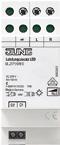
• Mounting on DIN rail according to EN 60715 in distribution boxes
Product characteristics
• Connection of several amplifiers to a single dimmer
• The total power of the connected loads is divided between the dimmer and amplifiers
• Power is supplied to the connected loads via a common power cable
• Operation using upstream dimmer
• Electronic over-temperature protection
• Optional accessory: compensation module LED, ref.-no.: KM LED 230 U
Technical data
Rated voltage: AC 230 V ~
Mains frequency: 50/60 Hz
Stand-by power: approx. 0.5 W
Power loss: approx. 4.3 W
Ambient temperature: −5 ... +45 °C
Connection: screw terminals single wire:
1 x 0.75 ... 4.0 mm2
2 x 0.75 ... 2.5 mm2
stranded without ferrule: 1 x 0.75 ... 4.0 mm2
stranded with ferrule:
2 x 0.75 ... 2.5 mm2
1 x 0.5 ... 2.5 mm2
Total length power cable: max. 100 m
Mounting width: 36 mm (2 rail units)
Permissible load depends on dimmer, operation mode and type of load, see operating instructions
203
ULZ 1755 REG
KNX Actuators
KNX Actuators
Ref.-no.
KNX LED dimming actuator 4-gang Rail mounting device, 4 rail units
Intended use
3904 REG LED
• LED dimmer for controlling LEDs and LED modules 12 – 24 V (pulse width-modulated PWM)
• Mounting on DIN rail according to EN 60715 in distribution boxes
Product characteristics
• 4 individually configurable LED dimming channels
• Maximum output current of 5 A per channel
• At 24 V DC up to 480 W LED output
• Possible channel combinations:
– 4 x independent channels
– 2 x Tunable White channels
– 2 x independent channels, 1 x Tunable White channel
– 1 x RGB channel, 1 x independent channel
– 1 x RGBW channel
• Activation of the colour channels via "HSV" or "RGB"
• Integrated 230 V C-load relay to switch the LED power supply
• Integrated protection with on-site display against:
– Overcurrent
– Overvoltage
– Overtemperature
– Reverse polarity
Technical data
Rated voltage: AC 230 V ~
Mains frequency: 50 Hz
Rated current: 16 A (C load)
Power loss: max. 6 W
Connection
Connection mode: screw terminals single wire: 1 x 2.5 ... 4 mm2 stranded without ferrule: 4 mm2 stranded with ferrule: 2.5 mm2
KNX medium: TP 256
Rated voltage KNX: DC 21 ... 32 V SELV
Current consumption KNX: max. 18.9 mA
Connection, KNX: terminal
LED
Connection: DC 12 ... 24 V SELV < 20 A from device acc. to EN 61347-2-13 for LED modules with constant output voltage
Current consumption: 20 mA
Outputs Number: 4
Max. current per output: 5 A
For LED modules with constant input voltage to EN 62031. LED modules with shared anode.
PWM frequency: 488 / 600 Hz
Cable length: depending on the cable resistance (voltage drop)
Connection Connection mode: screw terminals
single wire: 4 mm2
stranded without ferrule: 4 mm2
Mounting width: 72 mm (4 rail units)
Ambient temperature: −5 ... +45 °C
Storage/transport temperature: −25 ... +70 °C
204
KNX LED dimming actuator 4-gang
Intended use
Ref.-no.
3904 EB LED
• LED dimmer for controlling LEDs and LED modules 12 – 24 V (pulse width-modulated PWM)
• Mounting in false ceilings, surface mounting or in/ under furniture
Product characteristics
• 4 individually configurable LED dimming channels
• Maximum output current of 5 A per channel
• At 24 V DC up to 480 W LED output
• Possible channel combinations:
– 4 x independent channels
– 2 x Tunable White channels
– 2 x independent channels, 1 x Tunable White channel
– 1 x RGB channel, 1 x independent channel
– 1 x RGBW channel
• Activation of the colour channels via "HSV" or "RGB"
• Integrated 230 V C-load relay to switch the LED power supply
• Integrated protection with on-site display against:
– Overcurrent
– Overvoltage
– Overtemperature
– Reverse polarity
Technical data
Rated voltage: AC 230 V ~
Mains frequency: 50 Hz
Rated current: 16 A (C load)
Power loss: max. 6 W
Connection
Connection mode: screw terminals single wire: 1 x 2.5 ... 4 mm2 stranded without ferrule: 4 mm2 stranded with ferrule: 2.5 mm2
KNX medium: TP 256
Rated voltage KNX: DC 21 ... 32 V SELV
Current consumption KNX: max. 18.9 mA
Connection, KNX: terminal
LED
Connection: DC 12 ... 24 V SELV < 20 A from device acc. to EN 61347-2-13 for LED modules with constant output voltage
Current consumption: 20 mA
Outputs
Number: 4
Max. current per output: 5 A
For LED modules with constant input voltage to EN 62031. LED modules with shared anode.
PWM frequency: 488 / 600 Hz
Cable length: depending on the cable resistance (voltage drop)
Connection
Connection mode: screw terminals single wire: 4 mm2
stranded without ferrule: 4 mm2
Dimensions (L x W x H): 196 x 40 x 32 mm
Protection level: IP 20
Protection class: II
Ambient temperature: −5 ... +45 °C
Storage/transport temperature: −25 ... +70 °C
205 KNX
Actuators
KNX Actuators
Ref.-no.
KNX control unit 1 – 10 V, 4-gang Rail mounting device, 4 rail units
ETS product family: Illumination
Product type: Dimmer
Intended use
• Switching and brightness setting for lamps with operating devices with 1 – 10 V interface
• Switching of electrical loads
• Mounting on DIN rail according to EN 60715 in distribution boxes
Product characteristics
• Manual switching of the relays is independent of the bus
• Switching of capacitive loads and the resulting high switch-on currents
• Flexible assignment of control inputs to switching outputs, e.g. to control RGBW lamps
• Operation of the switching outputs as a switching actuator
• Connection of different external conductors possible
• No additional power supply necessary
• Feedback of switching state and brightness value
• Switch position display
• Burn-in function for fluorescent lamps
• Switch-on and dimming behaviour can be set
• Time functions: switch-on delay, switch-off delay, staircase lighting timer with pre-warning function
• Integration into light scenes
• Operating hours counter
206
2194 REGHM
Technical data
KNX medium: TP 256
Rated voltage KNX: DC 21 ... 32 V SELV
Current consumption KNX: max. 6 mA
Power loss: max. 4 W
Ambient temperature: −5 ... +45 °C
Storage/transport temperature: −25 ... +70 °C
Control outputs
Control voltage: 1 ... 10 V
Control current per output: max. 100 mA
Cable length: max. 500 m (0.5 mm2)
Switching outputs
Contact type: floating relay contacts (μ contact)
Switching voltage AC: AC 250 / 400 V
Switching current 230 V AC1: 16 A
Switching current 230 V AC3: 10 A
Switching current 400 V AC1: 10 A
Switching current 400 V AC3: 6 A
Fluorescent lamps: 16 AX
Switching voltage DC: DC 12 ... 24 V
Switching current DC: 16 A
Min. switching current: 100 mA
Switch-on current 150 µs: 600 A
Switch-on current 600 µs: 300 A
Ohmic load: 3680 W
Capacitive load: 16 A / 200 µF
Lamp loads
Incandescent lamps: 3680 W
HV halogen lamps: 3680 W
LV halogen lamps with inductive transformers: 2000 VA electronic transformers: 2500 W
Fluorescent lamps T5/T8 non-compensated: 3680 W parallel compensated: 2500 W / 200 µF
lead-lag circuit: 3680 W / 200 µF
Compact fluorescent lamps non-compensated: 3680 W parallel compensated: 2500 W / 200 µF
Mercury vapour lamps non-compensated: 3680 W parallel compensated: 3680 W / 200 µF
Connection, outputs
Connection mode: screw terminals single wire: 1 x 0.5 ... 4 mm2 stranded without ferrule: 1 x 0.34 ... 4 mm2
stranded with ferrule: 1 x 0.14 ... 2.5 mm2
Mounting width: 72 mm (4 rail units)
KNX Actuators
207
KNX Actuators
Ref.-no.
KNX DALI gateway TW
Rail mounting device, 4 rail units with manual electronic operation and LED status indication
ETS product family: Illumination
Product type: Dimmer
New in V 02: compatible with DALI-2 acc. to IEC 62386
Intended use
• Controlling of luminaires and other applications with DALI operating device in KNX installations e.g. electronic ballast
• Mounting on DIN rail according to EN 60715 in distribution boxes
Product characteristics
• Control of up to 64 DALI devices in up to 32 groups
• Setting of colour temperature for luminaires with DALI Device Type 8 for tunable white acc. to IEC 62386-209
• compatible with DALI-2 acc. to IEC 62386
• Suitable for operation in emergency lighting systems
• Individual, group or central addressing
• 16 light scenes
• Effect control for dynamic lighting effects or colour games
• Read out DALI device state via KNX, e.g. brightness or luminaire error
• Manual operation of the DALI groups
• Restraint function
• Feedback of switching state and brightness value in bus and manual mode
• Collective feedback
• Central switching function
• Disabling function for each DALI group
• Separate ON and OFF delay
• Staircase lighting timer with pre-warning function
• Corridor function: when combined with motion detectors, reduced continuous lighting, if no motion is detected
• Online or offline project design of the DALI devices with ETS plug-in
• Short-circuit protection
• Surge voltage protection
• Overload protection
• Operating hours counter
• Signal of the global switching status of the DALI devices, e.g. to switch off the mains voltage of the DALI devices to avoid standby losses
• An individual DALI device can be exchanged during operation without software
• Linear or logarithmic dimming characteristic can be selected
208
2099 REGHE
Technical data
Rated voltage: AC 110 ... 240 V ~, 50/60 Hz
Rated voltage: DC 110 ... 240 V
Power loss: max. 3 W
Ambient temperature: −5 ... +45 °C
Storage/transport temperature: −25 ... +70 °C
Rated voltage DALI: DC 16 V
Number of DALI devices: max. 64
DALI transmission rate: 1.2 kbit/s
DALI protocol: EN 62386
Cable type: Sheathed cable 230 V, e,g. NYM
Cable length DALI with 1.5 mm2: max. 300 m with 1.0 mm2: max. 238 m with 0.75 mm2: max. 174 m with 0.5 mm2: max. 116 m
Mounting width: 72 mm (4 rail units)
Connection, power supply and DALI
Connection mode: screw terminals single wire: 1 x 0.5 ... 4 mm2
stranded without ferrule: 1 x 0.5 ... 4 mm2
stranded with ferrule: 1 x 0.5 ... 2.5 mm2
KNX medium: TP 256
Rated voltage KNX: DC 21 ... 32 V SELV
Power consumption KNX: typical 150 mW
Connection, KNX: terminal
KNX Actuators
DALI transformer for LV halogen lamps
Intended use
• Power supply for LV halogen lamps
• Switching and brightness adjustment is performed with DALI control units or push-buttons
• Installation in false ceilings or surface mounting
Product characteristics
• No-load proof
• Electronic short-circuit protection
• Electronic overload protection
• Electronic overtemperature protection
• Suitable for emergency current installation
Technical data
Rated capacity: 35 ... 105 W
Rated voltage: AC 230/240 V ~, 50/60 Hz
Output voltage: 11.5 V eff. ~ 40 kHz
Short-circuit protection: electronic protection without fuse
Output cable length: max. 2 m
Dimensions: 170 x 44 x 34 mm
Ambient temperature: max. 50 °C
Terminals: screw terminals
primary 1 x 0.5 ... 1.5 mm2
secondary 1 x 0.75 ... 2.5 mm2
Approvals: VDE
209
D SNT 105
Ref.-no.
KNX Multistation
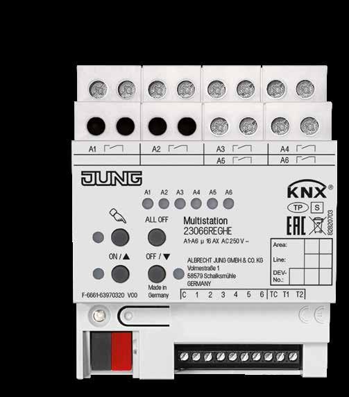
The KNX Multistation combines input and output channels in one compact device. Using logic functions, inter-device connections to the building control system are possible. In this way, functions are combined in one unit that otherwise can only be provided using multiple individual devices. This makes it optimal for rooms whose equipment is frequently repeated.
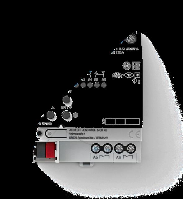
The JUNG KNX Multistation is a real problem solver. The REG housing has only 4 TE and offers a unique combination of six push-button interface, six switch outputs, two integrated room temperature controllers and two inputs for temperature sensors. This allows, for example, a complete office, hotel or hospital room to be equipped with all necessary
functions The configuration can be achieved if desired without ETS group addresses and can then simply be duplicated for all subsequent rooms. The Multistation is also ideal for retrofitting. Due to the low requirement for power supplies, the costs are of course also lower than for the use of individual actuators.
KNX Multistation Compact device for the distribution board
ROOM 2 ROOM 1 Outputs Binary inputs KNX line ACTUATORS/COMBINATION DEVICES 211 210 ACTUATORS/COMBINATION DEVICES
KNX Actuators
Ref.-no.
KNX multi station
Rail mounting device, 4 rail units
Intended use
• Switching of electrical loads with floating contacts • Switching of electrically-driven blinds, shutters, awnings and similar hangings • Switching of electrothermal drives • Polling of conventional switching or push-button contacts, window contacts etc. in KNX systems, for reporting of states, meter levels, operation of loads, etc.
• Polling of external temperature sensors for heating control • Logic functions to control building functions
• Mounting on DIN rail according to EN 60715 in distribution boxes
Product characteristics
• Actuator functions: switching, blinds, electrothermal drives • Actuator function can be switched in pairs
• Integrated push-button interface with 6 inputs • 2 integrated room temperature controllers • 2 inputs for temperature sensors (ref.-no. FF 7.8) • Outputs can be operated manually, construction site mode • Feedback in manual mode and in bus mode • Scene function • Disabling of individual outputs manually or via bus
Switching function
• Max. 6 switching outputs
• Operation as NO or NC contacts
• Logic operation and forcing function
• Feedback function
• Central switching function with collective feedback
• Time functions: switch-on delay, switch-off delay, staircase lighting timer with pre-warning function
Blinds function
• Max. 3 blinds outputs
• Suitable for 230 V AC motors
• Blind/shutter position directly controllable
• Slat position directly controllable
• Feedback of movement status, blind/shutter position and slat position
• Forced position through higher-level controller
• Safety function: rain alarm, frost alarm, 3 independent wind alarms
• Sun protection function
Function of valve drives
• Max. 2 outputs for electrothermal drives
• Switching operation or PWM operation
• Actuators with characteristics "normally open" or "normally closed" can be controlled
• Emergency operation in case of bus voltage failure for summer and winter
• Protection against jamming valves
• Forced position
• Cyclical monitoring of the input signals can be parameterised
Heating controller
• 2 internal controllers to control two independent rooms
• Control for heating or cooling, optionally with additional level
• On-off, PWM or PI control
• Predefined heating types (hot water heating, fan coil unit ...) or individual parameters possible
Inputs
• 6 inputs for push-buttons
• Input functions: switching, dimming, blinds control, light scene extension unit, brightness or temperature value transmitter
• 2 inputs for external temperature sensors
Logic functions
• Up to 10 logic operations with up to 8 inputs each, e.g. for AND, OR and XOR operations
• Conversion of data point types, e.g. from 1-bit to 8-bit
• Comparative operations, e.g. <, >, ≤, ≥
• Arithmetic functions, e.g. +, –, *, :
212
23066
REGHE
Technical data
KNX medium: TP 256
Rated voltage KNX: DC 21 ... 32 V SELV
Current consumption KNX: 4 ... 20 mA
Connection, KNX: terminal
Power loss: max. 6 W
Ambient temperature: −5 ... +45 °C
Storage/transport temperature: −25 ... +70 °C
Relay outputs
Contact type: floating relay contacts (μ contact)
Switch type: NO contact
Switching voltage: AC 250 V ~
Min. switching current AC: 100 mA
Switching current AC1 (cos ϕ > 0.8): 16 A
Switching current AC3 (cos ϕ < 0.8): 6 A
Fluorescent lamps: 16 AX
Switch-on current 200 µs: max. 800 A
Switch-on current 20 ms: max. 165 A
Switching voltage DC: DC 12 ... 24 V
Switching current DC 24 V: 6 A
Connected load, 230 V
Ohmic load:
KNX Actuators
1000 W
parallel compensated: 1160 W / 140 µF
Mercury vapour lamps non-compensated: 1000 W
parallel compensated: 1160 W / 140 µF
Electrothermal valve drives
Cycle time: min. 15 min
Connection, load
Connection mode: screw terminals
single wire: 1 x 0.5 ... 4 mm2
stranded without ferrule: 1 x 0.5 ... 4 mm2
stranded with ferrule: 1 x 0.5 ... 2.5 mm2
Inputs
Rated voltage: DC 3.3 V SELV
Signal duration: min. 100 ms
NO contacts: max. 50
NC contacts: max. 50
Cable length: max. 30 m
For cable lengths > 3 m, use shielded cables.
Connection, inputs:
Connection mode: screw terminals
single wire: 1 x 0.08 ... 1.5 mm2
stranded without ferrule: 1 x 0.08 ... 1 mm2
stranded with ferrule: 1 x 0.14 ... 0.5 mm2
Mounting width: 72 mm (4 rail units)
213
3000
W Blind / Fan motors: 1380 VA
3000
2500
Lamp loads 230 V Incandescent lamps:
W HV halogen lamps:
W
1500
1200
non-compensated: 1000
parallel
1160 W
lead-lag circuit: 2300 W
Compact fluorescent
non-compensated:
HV LED lamps: max. 400 W Electronic transformers:
W Inductive transformers:
VA Fluorescent lamps T5/T8
W
compensated:
/ 140 µF
/ 140 µF
lamps
KNX Actuators
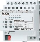
Ref.-no.
KNX room actuator 110 – 230 V Rail mounting device, 4 rail units with manual electronic operation and LED status indication Only with the ETS 3.0d version or later versions the full functionality will be available. ETS product family: Output Product type: Binary output
Intended use
• Switching of AC 110 ... 230 V electrical loads with floating contacts
• Switching of electrically-driven blinds, shutters, awnings and similar hangings
• Heating outputs: electronic outputs for switching electro-thermal valve drives
Product characteristics
• Outputs can be operated manually, construction site mode
• Feedback in manual mode and in bus mode
• Scene function
• Disabling of individual outputs manually or via bus
Switching function
• Operation as NO or NC contacts
• Logic operation and forcing function
• Feedback function
• Central switching function with collective feedback
• Time functions: switch-on delay, switch-off delay, staircase lighting timer with pre-warning function
Blinds function
• Suitable for 110 ... 230 V AC motors
• Blind/shutter position directly controllable
• Slat position directly controllable
• Feedback of movement status, blind/shutter position and slat position
• Forced position through higher-level controller
• Safety function: rain alarm, frost alarm, 3 independent wind alarms
• Sun protection function
Control of valve drives 230 V
• Switching operation or PWM operation
• Actuators with characteristics "normally open" or "normally closed" can be controlled
• Overload-protected, short circuit-protected
• Emergency operation in case of bus voltage failure for summer and winter
• Protection against jamming valves
• Forced position
• Cyclical monitoring of the input signals can be parameterised
214
RA 23024 REGHE
Technical data
KNX medium: TP 256
KNX supply: DC 21 ... 32 V SELV
Power consumption KNX: max. 150 mW
Power supply mains: AC 110 ... 230 V ~, 50/60 Hz
Power loss: max. 6 W
Ambient temperature: −5 ... +45 °C
Storing temperature: −25 ... +70 °C
Mounting width: 72 mm (4 rail units)
Connection, KNX: terminal
Connection, mains and outputs
Connection mode: screw terminals
single wire: 1 x 0.5 ... 4 mm2
stranded without ferrule: 1 x 0.5 ... 4 mm2
stranded with ferrule: 1 x 0.5 ... 2.5 mm2
Heating outputs
Number: 2
Contact type: semiconductor, ε
Switching voltage: AC 230/240 V ~
Switching current: 5 ... 50 mA
Switch-on current: max. 1.5 A (2 s)
Number of drives per output: max. 4
Relay outputs
Number: 4 (2 channels for operating blinds)
Contact type: floating NO contact (µ contact)
Switching voltage: AC 230/240 V ~
Breaking capacity AC1: 16 A
Breaking capacity AC3: 6 A
Breaking capacity fluorescent lamps: 16 AX
Switching capacities per output
Ohmic load: 3000 W
Capacitive load: 16 A / max. 140 µF
Motors: 1380 VA
Lamp loads
Incandescent lamps: 3000 W
HV halogen lamps: 2500 W
LV halogen lamps with electronic transformers: 1500 W
inductive transformers: 1200 VA
Fluorescent lamps
non-compensated: 1000 W
parallel compensated: 1160 W / max. 140 µF
– lead-lag circuit: 2300 W / max. 140 µF
Approvals: VDE
KNX Actuators
215
KNX Actuators
KNX fan coil actuator 2-gang
Rail mounting device, 4 rail units with manual electronic operation and LED status indication Only with the ETS 3.0d version or later versions the full functionality will be available.
ETS product family: Heating, A/C, Ventilation
Product type: Fan-coil
Product characteristics
• Connection of a fan coil unit with up to 6 fan speeds or connection of fan coil units with up to 3 fan speeds respectively
• Outputs can be operated manually, construction site mode
• Modes for heating, cooling or combined heating/cooling operations
• 2-pipe or 4-pipe operation
• Individual or hierarchical switching of fan speeds
• Feedback
• Disabling function for each channel
Operation modes
• Bus operation: operation via touch sensors or room controller
• Temporary manual control: manual operation locally with keypad, automatic return to bus operation
• Permanent manual control mode: only manual operation locally on device
Technical data
KNX medium: TP 256
KNX supply: DC 21 ... 32 V SELV
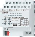
Power consumption KNX: typical 150 mW
Rated voltage: AC 230/240 V ~, 50/60 Hz
Power loss: max. 3 W
Ambient temperature: −5 ... +45 °C
Storing temperature: −25 ... +70 °C
Connection, KNX: terminal
Connection, mains and outputs
Connection mode: screw terminals
single wire: 1 x 0.5 ... 4 mm2
stranded without ferrule: 1 x 0.5 ... 4 mm2
stranded with ferrule: 1 x 0.5 ... 2.5 mm2
Switch type: NO contact
Contact type: floating relay contacts (μ contact)
Switching voltage: AC 230/240 V ~
Breaking capacity AC1: 10 A
Breaking capacity AC3: 10 A
Switching capacities per output
Ohmic load: 2300 W
Capacitive load: 10 A / max. 140 µF
Motors: 1380 VA
Lamp loads
Incandescent lamps: 2300 W
HV halogen lamps: 2300 W
LV halogen lamps with
inductive transformers: 1200 VA
electronic transformers: 1500 W
Fluorescent lamps
non-compensated: 1000 W
parallel compensated: 1160 W / 140 µF
lead-lag circuit: 2300 W / 140 µF
Approvals: VDE
216
Ref.-no.
FCA 2 REGHE
KNX heating actuator, 6-gang Rail mounting device, 4 rail units 6 outputs "TRIAC" with manual electronic operation and LED status indication ETS product family: Heating, A/C, Ventilation
Product type: Valve
Intended use
• Switching of electrothermal actuators for heaters or cooling ceilings
• Installation in distribution boxes on DIN rail according to EN 60715
Product characteristics
• Switching operation or PWM operation
• Actuators with characteristics "normally open" or "normally closed" can be controlled
• Valve drives for 230 V or 24 V controllable
• Outputs can be operated manually, construction site mode
• Feedback in manual mode and in bus mode
• Disabling of individual outputs manually or via bus
• Overload-protected, short circuit-protected; error indication with LED
• Protection against jamming valves
• Forced position
• Various setpoints for forced position or emergency operation in case of bus failure for summer or winter
• Cyclical monitoring of the input signals can be parameterised
• Feedback via bus, e.g. in case of mains failure, overload or sensor failure
Technical data
Rated voltage: AC 110 ... 230 V ~, 50/60 Hz
Stand-by power: max. 0.4 W
Power loss: max. 1 W
KNX medium: TP 256
Rated voltage KNX: DC 21 ... 32 V SELV
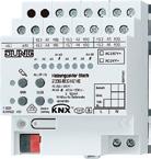
Power consumption KNX: max. 250 mW
Ambient temperature: −5 ... +45 °C
Storage/transport temperature: −25 ... +70 °C
Heating outputs
Contact type: semiconductor (triac), ε
Switching voltage: AC 24 / 230 V ~
Mains frequency: 50/60 Hz
Switching current: 5 ... 160 mA
Switch-on current: max. 1.5 A (2 s)
Switch-on current: max. 0.3 A (2 min)
Number of drives per output
230 V drives: max. 4
24 V drives: max. 2
Mounting width: 72 mm (4 rail units)
Connection, outputs
Connection mode: screw terminals
single wire: 1 x 0.5 ... 4 mm2
stranded without ferrule: 1 x 0.5 ... 4 mm2
stranded with ferrule: 1 x 0.5 ... 2.5 mm2
217 KNX
Ref.-no.
Actuators
2336 REG HZ HE
KNX Actuators
Ref.-no.
KNX heating actuator, 6-gang with controller
Rail mounting device, 4 rail units
6 outputs "TRIAC" with manual electronic operation and LED status indication
ETS product family: Heating, A/C, Ventilation
Product type: Valve
Intended use
• Switching of electrothermal actuators for heaters or cooling ceilings
• Installation in distribution boxes on DIN rail according to EN 60715
Product characteristics
• Integrated room temperature control with setpoint value specification
• Six independent controllers to control up to six independent rooms
• Controller function for heating and cooling
• Switching operation or PWM operation
• Actuators with characteristics "normally open" or "normally closed" can be controlled
• Valve drives for 230 V or 24 V controllable
• Outputs can be operated manually, construction site mode
• Feedback in manual mode and in bus mode
• Disabling of individual outputs manually or via bus
• Overload-protected, short circuit-protected; error indication with LED
• Protection against jamming valves
• Forced position
• Various setpoints for forced position or emergency operation in case of bus failure for summer or winter
• Cyclical monitoring of the input signals can be parameterised
• Feedback via bus, e.g. in case of mains failure, overload or sensor failure
Technical data
Rated voltage: AC 110 ... 230 V ~, 50/60 Hz
Stand-by power: max. 0.4 W
Power loss: max. 1 W
KNX medium: TP 256
Rated voltage KNX: DC 21 ... 32 V SELV
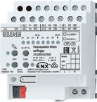
Power consumption KNX: max. 250 mW
Ambient temperature: −5 ... +45 °C
Storage/transport temperature: −25 ... +70 °C
Heating outputs
Contact type: semiconductor (triac), ε
Switching voltage: AC 24 / 230 V ~
Mains frequency: 50/60 Hz
Switching current: 5 ... 160 mA
Switch-on current: max. 1.5 A (2 s)
Switch-on current: max. 0.3 A (2 min)
Number of drives per output
230 V drives: max. 4
24 V drives: max. 2
Mounting width: 72 mm (4 rail units)
Connection, outputs
Connection mode: screw terminals
single wire: 1 x 0.5 ... 4 mm2
stranded without ferrule: 1 x 0.5 ... 4 mm2
stranded with ferrule: 1 x 0.5 ... 2.5 mm2
218
2336 REG HZR HE
Ref.-no.
KNX analogue actuator, 4-gang
Rail mounting device, 4 rail units
ETS product family: Output
Product type: Analogue output 4-gang
The analogue output needs 24 V AC for operation.
The necessary power can be supplied by the power supply unit ref.-no.: WSSV 10.
Function
• The analogue output converts measuring data received via KNX telegrams (1-byte and 2-byte telegrams) into analogue output signals.
• The analogue output signals enable heating, ventilation and air conditioning units to adapt their output values to information received from the bus and thus to take part in control processes.
• The outputs are software-parameterized for voltage or current signals.
Voltage signals: 0 ... 1 V, 0 ... 10 V
Current signals: 0 ... 20 mA, 4 ... 20 mA
• Voltage outputs are monitored for short circuits.
• The output state is indicated by status LEDs.
• With the analogue actuator module, 4-gang (ref.no. 2204.01 REGAM), the number of analog outputs can be increased from 4 to 8. The connection is made via a system plug.
• The output variables can be forced.
• Outputs that are not required can be switched off.
Connectable analogue actuators
• Do not connect electronic ballasts or electronic transformers with 1 – 10 V control input to the outputs.
• Do not connect external voltages to the outputs. All connected components must ensure safe separation from other voltages.
• Current outputs may be loaded with 500 Ω max.
• Voltage outputs must be loaded with 1 kΩ min.
• The GND terminals of the outputs K1 ... K4 are connected internally.
• In the event of a short-circuit between a voltage output K1 ... K4 and GND, the respective output is deactivated.
Technical data
Power supply
Supply voltage: AC 24 V ~ ± 10 %
Current consumption: max. 308 mA
KNX medium: TP 256
Rated voltage KNX: DC 21 ... 32 V SELV
Power consumption KNX: typical 150 mW
Ambient temperature: −5 ... +45 °C
Storage/transport temperature: −25 ... +70 °C
Humidity
Ambient/storage/transport: max. 93 % r. h., no condensation
Mounting width: 72 mm (4 rail units)
Weight: approx. 180 g
Terminals
Outputs, power supply: screw terminals
single wire: 1 x 0.5 ... 4 mm2
stranded without ferrule: 1 x 0.5 ... 4 mm2
stranded with ferrule: 1 x 0.5 ... 2.5 mm2
Connection, KNX: bus connection block
Analogue outputs
Number: 4
Ranges: 0 ... 1 V DC, 0 ... 10 V DC, 0 ... 20 mA DC, 4 ... 20 mA, DC
Voltage signal load: ≥ 1 kW
Current signal load: ≤ 500 W
Power supply analogue actuator module: DC 24 V via system bus max. 80 mA
219 KNX Actuators
2204.01 REGA
KNX Actuators
Ref.-no.
Analogue actuator module, 4-gang Rail mounting device, 4 rail units
Extension module for analogue actuator 4-gang ref.-no.: 2204.01 REGA
Function
• The analogue actuator module extends a KNX analogue actuator 4-gang by four additional sensor outputs, which can be parameterised by software.
• Received data are converted into the output signals 0 ... 1 V, 0 ... 10 V, 0 ... 20 mA, or 4 ... 20 mA
• The analogue output signals enable heating, ventilation and air conditioning units to adapt their output values to information received from the bus and thus to take part in control processes.
• The output variables can be forced.
• The evaluation of the module data itself and the processing of the forced operation takes place in the KNX analog output.
• The analogue output module is connected to the KNX device via a system plug included in the scope of delivery.
• Outputs that are not required can be switched off.
• Voltage outputs are monitored for short circuits.
• The output state is indicated by status LEDs.
Connectable analogue actuators
• Do not connect electronic ballasts or electronic transformers with 1 – 10 V control input to the outputs.
• Do not connect external voltages to the outputs. All connected components must ensure safe separation from other voltages.
• Current outputs may be loaded with 500 Ω max.
• Voltage outputs must be loaded with 1 kΩ min.
• The GND terminals of the outputs K1 ... K4 are connected internally.
• In the event of a short-circuit between a voltage output K1 ... K4 and GND, the respective output is deactivated.
220
2204.01 REGAM
Technical data
Power supply
Supply voltage: AC 24 V ~ ± 10 %
Current consumption: max. 120 mA
Current consumption at system
connector: 6 mA
Ambient temperature: −5 ... +45 °C
Storage/transport temperature: −25 ... +70 °C
Humidity
Ambient/storage/transport: max. 93 % r. h., no condensation
Mounting width: 72 mm (4 rail units)
Weight: approx. 155 g
Terminals
Outputs, power supply: screw terminals
single wire: 1 x 0.5 ... 4 mm2
stranded without ferrule: 1 x 0.5 ... 4 mm2
stranded with ferrule: 1 x 0.5 ... 2.5 mm2
Connection KNX device: KNX bus connection block
Analogue outputs
Number: 4
Ranges: 0 ... 1 V DC, 0 ... 10 V DC, 0 ... 20 mA DC, 4 ... 20 mA, DC
Voltage signal load: ≥ 1 kW
Current signal load: ≤ 500 W
KNX Actuators
221
KNX Flush-mounted actuators
Discontinued
Delivery capacity is ensured until April 2021.
Successor: 23001 1S U
Flush-mounted KNX switch actuator, 1-gang with satellite input
1 NO contact, 2 binary inputs
ETS product family: Output
Product type: Binary output
Intended use
• Switching of electrical loads for AC 230 V mains voltage
• Installation in flush box according to DIN 49073
• Connection with enclosed terminals
Product characteristics
Ref.-no.
2131.16 UP
• Two binary inputs for potential-free contacts, usable as extension inputs for local operation
• Operation as NO or NC contacts
• Feedback function
• Additional function: logical, forced-position or time function
• Time functions: switch-on delay, switch-off delay, staircase lighting timer
• Supply via bus, no additional power supply necessary
Technical data
Output
Number: 1
Switch type: floating NO contact (μ contact)
Max. switching voltage: AC 230 V ~
Max. switching current: 16 A at 230 V AC
Switching capacity
Incandescent lamps: 2200 W
HV halogen lamps: 2200 W
Capacitive load: AC 230 V, 10 A, max. 105 µF
Inductive transformers: 1000 VA
Terminals
Output cable:
L and L’, colour brown, 1.5 mm2, length approx. 20 cm
Bus and control cable: KNX + red
KNX – black
binary input 1 green GND white binary input 2 yellow GND brown length approx. 33 cm, extendible to 5 m max.
Satellite input: depending on parameterisation either as extension inputs for push-button local control of the actuator or as independent binary inputs acting on the bus
Dimensions (Ø x H): 53 x 28 mm
KNX medium: TP 64
Rated voltage KNX: DC 21 ... 32 V SELV
Connection, KNX: terminal
Power consumption KNX: typical 150 mW
Approvals: VDE
222
Flush-mounted actuators
Discontinued
Delivery capacity is ensured until April 2021.
Successor: 23002 1S U
Flush-mounted KNX switch actuator, 2-gang with satellite input
2 NO contacts, 2 binary inputs
ETS product family: Output
Product type: Binary output
Intended use
• Switching of electrical loads for AC 230 V mains voltage
• Installation in flush box according to DIN 49073
• Connection with enclosed terminals
Product characteristics
2132.6 UP
• Two binary inputs for potential-free contacts, usable as extension inputs for local operation
• Operation as NO or NC contacts
• Feedback function for each output
• An additional function for each output: logical, forced-position or time function
• Time functions: switch-on delay, switch-off delay, staircase lighting timer
• Supply via bus, no additional power supply necessary
Technical data
Output
Number: 2
Contact type: floating relay contacts (μ contact)
Switch type: NO contact
Max. switching voltage: AC 230 V ~
Max. switching current: 2 x 6 A at 230 V AC
Switching capacity
Incandescent lamps: 1200 W
HV halogen lamps: 1200 W
Capacitive load: AC 230 V, 6 A, max. 14 µF
Inductive transformers: 500 VA
Electronic transformers: 500 W
Terminals
Output cable: L, L'1, L'2, black, pink, grey, 1.5 mm2, length approx. 20 cm
Bus and control cable: KNX + red
KNX – black
binary input 1 green
GND white
binary input 2 yellow
GND brown
length approx. 33 cm, extendible to 5 m max.
Satellite input: depending on parameterisation either as extension inputs for push-button local control of the actuator or as independent binary inputs acting on the bus
Dimensions (Ø x H): 53 x 28 mm
KNX medium: TP 64
Rated voltage KNX: DC 21 ... 32 V SELV
Connection, KNX: terminal
Power consumption KNX: typical 150 mW
Approvals: VDE
Ref.-no. 223 KNX
KNX Flush-mounted actuators
Discontinued Delivery capacity is ensured until April 2021.
Flush-mounted KNX room climate interface with satellite input
3 binary inputs
1 blinds output, 1 output "TRIAC" (heating)
Intended use
Ref.-no.
2531
UP
• Switching of electrically-driven blinds, awnings and similar blinds for AC 230 V mains voltage
• Switching of electrothermal actuators • Installation in flush box according to DIN 49073 • Connection with enclosed terminals
Product characteristics
• Control of blinds, awnings and similar blinds • Control of electrothermal actuators • Three binary inputs for potential-free contacts, usable as extension inputs for local operation • Supply via bus, no additional power supply necessary
Blinds function
• Blind/shutter position directly controllable • Slat position directly controllable • Feedback of movement status, blind/shutter position and slat position • Forced position through higher-level controller • Safety function: rain alarm, frost alarm, 3 independent wind alarms • Sun protection function
Function of valve drives
• Switching operation or PWM operation
• Actuators with characteristics "normally open" or "normally closed" can be controlled • Overload-protected, short circuit-protected • Protection against jamming valves • Forced position • Cyclical monitoring of the input signals can be parameterised
PWM operation: electrothermal actuators only have the positions Open and Closed. In PWM operation, switch-on and switch-off during the drive’s cycle time achieves an almost constant behaviour.
Technical data
Rated voltage: AC 230/240 V ~, 50/60 Hz
Switching voltage: AC 250 V ~
Ambient temperature: −5 ... +45 °C
Storage/transport temperature: −25 ... +70 °C
Blinds output
Contact type: µ
Switching current AC1 (cos ϕ > 0.8): 3 A
Min. switching current AC: 100 mA
Motors (230 V): 600 VA
Heating output
Contact type: semiconductor (triac), ε
Switching current: 5 ... 25 mA
Switch-on current: max. 600 mA (2 s)
Number of drives per output: max. 2
Control cable
Cable type: YY6x0.6
Input type: floating contact
Total cable length: max. 5 m
Voltage satellite inputs: approx. 5 V
Dimensions (Ø x H): 53 x 28 mm
Connection: screwles terminals
single wire: 1 x 1 ... 2.5 mm2
KNX medium: TP 64
KNX supply: DC 21 ... 32 V SELV
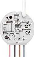
Power consumption KNX: max. 240 mW
Connection, KNX: terminal
Approvals: VDE
224
Flush-mounted actuators
Discontinued
Delivery capacity is ensured until April 2021.
Successor: 23002 1S U
Flush-mounted KNX blinds actuator, 1-gang with satellite input
3 binary inputs
ETS product family: Shutter
Product type: Shutter
Intended use
2501 UP
• Switching of electrically-driven blinds, awnings and similar blinds for AC 110 ... 230 V mains voltage
• Installation in flush box according to DIN 49073
• Connection with enclosed terminals
Product characteristics
• Control of blinds, awnings and similar blinds
• Three binary inputs for potential-free contacts, usable as extension inputs for local operation
• Supply via bus, no additional power supply necessary
• Blind/shutter position directly controllable
• Slat position directly controllable
• Feedback of movement status, blind/shutter position and slat position
• Forced position through higher-level controller
• Safety function: rain alarm, frost alarm, 3 independent wind alarms
• Sun protection function
Technical data
Rated voltage: AC 110 ... 240 V ~, 50/60 Hz
Switching voltage: AC 250 V ~
Ambient temperature: −5 ... +45 °C
Storage/transport temperature: −25 ... +70 °C
Blinds output
Contact type: µ
Switching current AC1 (cos ϕ > 0.8): 3 A
Min. switching current AC: 100 mA
Motors (230 V): 600 VA
Motors (110 V): 300 VA
Control cable
Cable type: YY6x0.6
Input type: floating contact
Total length of control cable: max. 5 m
Voltage satellite inputs: approx. 5 V
Dimensions (Ø x H): 53 x 28 mm
Connection Connection mode: screwles terminals
single wire: 1 x 1 ... 2.5 mm2
KNX medium: TP 64
KNX supply: DC 21 ... 32 V SELV
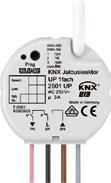
Power consumption KNX: max. 240 mW
Connection, KNX: terminal
Approvals: VDE
Ref.-no. 225 KNX
KNX Flush-mounted actuators
Discontinued
Delivery capacity is ensured until April 2021.
Successor: 39001 1S U
Flush-mounted KNX dimming actuator, 1-gang, 50 – 210 W/VA with satellite input
2 binary inputs
ETS product family: Illumination
Product type: Dimmer
Intended use
• Switching of electrothermal actuators
• Installation in flush box according to DIN 49073
• Connection with enclosed terminals
Product characteristics
Ref.-no.
3210 UP
• Three binary inputs for potential-free contacts, usable as extension inputs for local operation
• Supply via bus, no additional power supply necessary
• Switching operation or PWM operation
• Actuators with characteristics "normally open" or "normally closed" can be controlled
• Overload-protected, short circuit-protected
• Protection against jamming valves
• Forced position
• Cyclical monitoring of the input signals can be parameterised
Technical data
Output: 1 Power MOS-FET
Dimming method: trailing edge or leading edge phase control
Terminals
Output cable: L = black, dimming output = brown, 0.75 mm2 length approx. 20 cm
Bus and control cable: KNX + red KNX – black binary input 1 green GND white binary input 2 yellow GND brown length approx. 33 cm, extendible to 5 m max.
Satellite input: depending on parameterisation either as extension inputs for push-button local control of the actuator or as independent binary inputs acting on the bus
Dimensions (Ø x H): 63 x 25 mm
Rated voltage: AC 230 V ~, 50/60 Hz
Rated current: 0.9 A
Minimum load: 50 W
Power loss: 2 W
Connected load
Total connected load: 210 W/VA
Ohmic load: 50 ... 210 W
Incandescent lamps: 50 ... 210 W
HV halogen lamps: 50 ... 210 W
LV halogen lamps with inductive transformers: 50 ... 210 VA
electronic transformers: 50 ... 210 VA
Mix of the specified load types (do not mix capacitive loads with inductive loads).
When using mixed loads with inductive transformers, the ohmic load must not exceed 50 %.
KNX medium: TP 64
Rated voltage KNX: DC 21 ... 32 V SELV
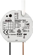
Power consumption KNX: typical 150 mW
Connection, KNX: terminal
Approvals: VDE
226
Flush-mounted actuators
Discontinued Delivery capacity is ensured until March 2021.
Flush-mounted KNX heating actuator, 1-gang with satellite input
3 binary inputs
1 output "TRIAC"
ETS product family: Heating, A/C, Ventilation
Product type: Valve
Intended use
• Switching of electrothermal actuators
• Installation in flush box according to DIN 49073
• Connection with enclosed terminals
Product characteristics
2501 HZ UP
• Three binary inputs for potential-free contacts, usable as extension inputs for local operation
• Supply via bus, no additional power supply necessary
• Switching operation or PWM operation
• Actuators with characteristics "normally open" or "normally closed" can be controlled
• Overload-protected, short circuit-protected
• Protection against jamming valves
• Forced position
• Cyclical monitoring of the input signals can be parameterised
PWM operation: electrothermal actuators only have the positions Open and Closed. In PWM operation, switch-on and switch-off during the drive’s cycle time achieves an almost constant behaviour.
Technical data
Rated voltage: AC 230/240 V ~, 50/60 Hz
Switching voltage: AC 250 V ~
Ambient temperature: −5 ... +45 °C
Storage/transport temperature: −25 ... +70 °C
Heating output
Contact type: semiconductor (triac), ε
Switching current: 5 ... 25 mA
Switch-on current: max. 600 mA (2 s)
Number of drives per output: max. 2
Control cable
Cable type: YY6x0.6
Input type: floating contact
Total length of control cable: max. 5 m
Voltage satellite inputs: approx. 5 V
Dimensions (Ø x H): 53 x 28 mm
Connection
Connection mode: screwles terminals
single wire: 1 x 1 ... 2.5 mm2
KNX medium: TP 64
Rated voltage KNX: DC 21 ... 32 V SELV
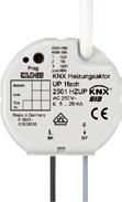
Power consumption KNX: max. 240 mW
Connection, KNX: terminal
Approvals: VDE
227 KNX
Ref.-no.
KNX Motor-operated valve drive
KNX valve drive (motor-operated) with controller
electromechanical servo drive
ETS product family: Heating, A/C, Ventilation
Product type: Valve
Intended use
• Motor-operated valve drive for heating or cooling valves
• To be screwed on valve head
Product characteristics
• Integrated temperature sensor

• Room temperature control
• Mechanical indication of valve lift
• Automatic detection of valve lift
Ref.-no.
2177 SV R
• One input, can be used as binary input or for an external temperature sensor (ref.-no.: FF 7.8)
• Use in heating circles possible
• Integrated bus coupling unit
• Valve protection function
Technical data
KNX medium: TP 256
Rated voltage KNX: DC 21 ... 32 V SELV
Current consumption KNX: max. 20 mA
Protection class: III
Valve connection: M 30 x 1.5
Valve lift: 1.0 ... 4.2 mm
Actuating power: 80 ... 120 N
Dimensions (L x W x H): 76 x 47 x 85 mm
Connection cable
Cable type: J-YY 1 × 2 × 0.6 mm
Cable length: 1 m
Total length per line: max. 30 m
Number of drives per line: max. 30
Connection cable, binary input/external sensor
Voltage satellite inputs: approx. 3.3 V
Cable length: max. 10 m
single wire: 1 x 0.08 ... 1.5 mm2
stranded without ferrule: 1 x 0.08 ... 1 mm2
stranded with ferrule: 1 x 0.14 ... 0.5 mm2
Protection level: IP 40
Ambient temperature: 0 ... +50 °C
Storage/transport temperature: −20 ... +70 °C
Relative humidity: 5 ... 95 % (no condensation)
228
Motion detector mini basic
white
Intended use
• Brightness-independent detection of motions in interior areas
Ref.-no.
N IP BM 360 MB WW
• Connection to KNX e.g. multi station or push-button interface for automatic switching of loads
• Power supply via unchoked output of a (KNX) power supply with SELV
• Clamp mounting in suspended ceilings
• Ceiling installation on fixed ceilings in appliance box according to DIN 49073 with flush mounting set (ref.-no.: PMM-UP-SET-WW)
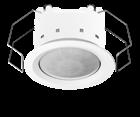
• Surface-mounted ceiling installation with surface mounting set (ref.-no.: PMM-AP-SET-WW)
Product characteristics
• Brightness-independent detection of motions in the detection field
• Switch on: After detection of a motion
• Switch off: No motion in the detection field and shut-off delay elapsed
• Floating electronic switching contact
Technical data
Rated voltage: DC 24 ... 32 V SELV
Stand-by power: < 0.1 W
Current consumption: max. 4 mA
Ambient temperature: −5 ... +45 °C
Storage/transport temperature: −25 ... +70 °C
Relative humidity: 10 ... 100 % (no condensation)
Protection class: III
Protection level: IP 44
Motion detection
Detection angle: 360°
Range: Ø approx. 6 m (mounting height 3 m)
Shut-off delay: approx. 10 s
Switching output
Electric strength: 40 V
Current carrying capacity of device: max. 50 mA
Connected load: max. 0.15 W
Dimensions
Ceiling cut-out (Ø x D): 44 x 35 mm
Dimensions (Ø x H): 53.5 x 38 mm (with design ring)
Cable length: max. 30 m
Max. thickness of the suspended ceiling: approx. 25 mm
Installation depth: min. 35 mm
Distance between concrete ceiling and suspended ceiling: min. 20 mm
Design ring Ø inside: 35.6 mm
Design ring Ø outside: 53.5 mm
Profile height design ring: 1.8 mm
Profile height lens: 5.5 mm
229 KNX Sensors
KNX Sensors
Ref.-no.
Condensation sensor
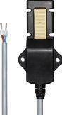
Intended use
BTS 01
• Detection of water condensation on coolant lines in residential or functional buildings • Connection to KNX push-button interfaces or other binary inputs with 5 V polling voltage (e.g. 2177 SV R, 2076-2 T, 2076-4 T, .. 2178 TS .., .. 2178 ORTS .., CO2 .. 2178 ..) • Fitting on the coolant line
Technical data
Rated voltage: DC 3.3 ... 5 V SELV
Current consumption: typical 0.5 mA
Short-circuit current: max. 100 mA
Protection class: III
Ambient temperature: 0 ... +50 °C
Length of connected cable: 2 m
Protection level: IP 67
Leakage sensor
Intended use
LES 01
• Detection of water penetration and leaks • Connection to KNX push-button interfaces or other binary inputs with 5 V polling voltage (e.g. 2177 SV R, 2076-2 T, 2076-4 T, .. 2178 TS .., .. 2178 ORTS .., CO2 .. 2178 ..)
• Fitting to the surface to be monitored
Application examples
• Below or next to the bathtub or shower • Under the kitchen unit • Below or behind washing machines
• In boiler rooms • In supply shafts with water pipes • In cellar rooms with a risk of backflow • Below or behind aquariums • In the heating manifold of floor heating systems
Technical data
Rated voltage: DC 3.3 ... 5 V SELV
Current consumption: typical 0.5 mA
Short-circuit current: max. 100 mA
Protection class: III
Ambient temperature: 0 ... +50 °C
Length of connected cable: 2 m
Protection level: IP 67
Magnet contact
white similar RAL 9016
brown
FUS 4410 WW
FUS 4410 BR
A sealed tubular glass envelope protects the magnet contact (reed contact) against dust and water. The reed contact is actuated by means of a permanent magnet. For installation in steel profiles (magnetic material) only block reed contacts can be used. Included in delivery:
2 surface-mounted housings, 2 caps,
3 spacers 2 mm
1 spacer 6 mm
To be integrated into the signalling system of the Smart Panels by the KNX system via binary inputs / push-button interfaces.
Technical data
Contact type: 1-pole, 1-way (NO contact)
Switching voltage: max. 100 V DC
Switching current: max. 0.5 A
Contact rating: max. 10 W or 10 VA
Transition resistance: 0.15 Ω
Permissible operating voltage: max. 40 V
Connection cable: LIYY 2 x 0.14 mm, Ø 3.2 mm (length 3 m)
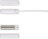
Dimensions:
Contact = 32 mm x Ø 8 mm
Magnet = 30 mm x Ø 6 mm AINICo 5
Housing (LxWxH) = 54 x 13 x 13 mm
230
KNX binary input, 6-gang Rail mounting device, 2 rail units 6 inputs AC/DC 10 ... 230 V ~ (different L conductors possible, e.g.: E1-3 = L1 and E4-E6 = L2) with status indicator
ETS product family: Input
Product type: Binary input
Intended use
• Polling of conventional switching or push-button contacts, window contacts etc. in KNX systems, for reporting of states, meter levels, operation of loads, etc.
• Mounting on DIN rail according to EN 60715 in distribution boxes
Product characteristics
• Status LED for each input
• Detection of voltage levels and changes on the input
• Transmitting of input status to the bus
• Transmitting behaviour freely adjustable
• Functions: switching, dimming, blinds up/down, brightness values, temperatures, calling up and saving light scenes, etc.
• Impulse and switch counter function
• Inputs can be blocked separately
• Connection of external AC or DC voltages
Technical data
KNX medium: TP 256
Rated voltage KNX: DC 21 ... 32 V SELV
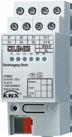
Current consumption KNX: max. 7.5 mA
Connection, KNX: terminal
Ambient temperature: −5 ... +45 °C
Storage/transport temperature: −25 ... +75 °C
Relative humidity: max. 93 % (no condensation)
Inputs
Rated voltage: AC/DC 10 ... 230 V
Signal level "0" signal: AC/DC 0 ... 2 V
Signal level "1" signal: AC/DC 7 ... 265 V
Input current at rated voltage:
Input current: approx. 0.7 mA
Rated frequency AC signal: 30 ... 60 Hz
Signal duration pulse counter: min. 100 ms
Cable length: max. 100 m
Number of contacts per input
NO contacts: max. 50
NC contacts: max. 50
Mounting width: 36 mm (2 rail units)
Power loss: max. 1 W
Connection
Connection mode: screw terminals
single wire: 1 x 0.5 ... 4 mm2
stranded without ferrule: 1 x 0.5 ... 4 mm2
stranded with ferrule: 1 x 0.5 ... 2.5 mm2
231 KNX Sensors
Ref.-no.
2116 REG
KNX Sensors
KNX binary input, 8-gang Rail mounting device, 4 rail units 8 inputs 12 ... 48 V AC/DC
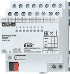
Auxiliary voltage output DC 24 V (SELV) for polling potential-free contacts with status indicator
ETS product family: Input
Product type: Binary input
Intended use
• Polling of conventional switching or push-button contacts, window contacts etc. in KNX systems, for reporting of states, meter levels, operation of loads, etc.
• Mounting on DIN rail according to EN 60715 in distribution boxes
Product characteristics
• Status LED for each input
• Detection of voltage levels and changes on the input
• Transmitting of input status to the bus
• Transmitting behaviour freely adjustable
• Functions: switching, dimming, blinds up/down, brightness values, temperatures, calling up and saving light scenes, etc.
• Inputs can be blocked separately
• Connection of external AC or DC voltages
• Auxiliary voltage output for polling potential-free contacts
• No separate power supply required
• Separate reference potentials for inputs
• Pulse counter (firmware version V02 or higher), also suitable for S0 pulses
Technical data
KNX medium: TP 256
Rated voltage KNX: DC 21 ... 32 V SELV
Power consumption KNX: max. 350 mW
Stand-by: max. 200 mW
Connection, KNX: terminal
Ambient temperature: −5 ... +45 °C
Storage/transport temperature: −25 ... +70 °C
Inputs
Rated voltage: AC/DC 12 ... 48 V
Signal level "0" signal: AC/DC −48 ... +2 V
Signal level "1" signal: AC/DC 8 ... 48 V
Input current at rated voltage: Input current: 2 mA
Signal duration: min. 30 ms
Rated frequency AC signal: 30 ... 60 Hz
Number of contacts per input
NO contacts: unlimited
NC contacts: max. 20
Output voltage: DC 24 V SELV
Mounting width: 72 mm (4 rail units)
Stand-by power: max. 200 mW
Power loss: max. 1 W
Connection
Connection mode: screw terminals
single wire: 1 x 0.2 ... 4 mm2
stranded without ferrule: 1 x 0.34 ... 4 mm2
stranded with ferrule: 1 x 0.14 ... 2.5 mm2
Cable length: max. 100 m
232
Ref.-no.
2128 REG
KNX push-button interface, 2-gang
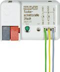
ETS product family: Input
Product type: Binary input
Product characteristics
• Can be used as binary input
• Can be used as switching output, e.g. for LEDs, max. 0.8 mA
Technical data
KNX medium: TP 256
Inputs Number: 2
Signal voltage: 5 V
Signal current: > 1 mA
Connection mode: branching terminal, 5 pins
Ref.-no.
2076-2 T
Length of input cable: 25 cm prefabricated, extendable to 5 m max
Outputs
Output voltage: 5 V with 3.9 kΩ series resistor (open-circuit voltage)
Output current: 2 mA for red low-current LED (at approx. 1.4 V)
Dimensions (W x H x D): 28 x 43 x 16 mm
KNX push-button interface, 4-gang
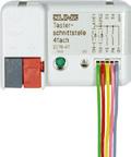
ETS product family: Input
Product type: Binary input
Product characteristics
• Can be used as binary input
• Can be used as switching output, e.g. for LEDs, max. 0.8 mA
Technical data
KNX medium: TP 256
Inputs Number: 4
Signal voltage: 5 V
Signal current: > 1 mA
Connection mode: branching terminal, 5 pins
2076-4 T
Length of input cable: 25 cm prefabricated, extendable to 5 m max
Outputs
Output voltage: 5 V with 3.9 kΩ series resistor (open-circuit voltage)
Output current: 2 mA for red low-current LED (at approx. 1.4 V)
Dimensions (W x H x D): 28 x 43 x 16 mm
233
KNX Sensors
KNX energy sensor
The KNX energy sensor has three channels for connecting to consumers. For each channel, energy amounts, voltage, current and effective and reactive power are measured. Alternatively, it also records three-phase current levels. The sensor cyclically sends the data for evaluation and visualisation to the KNX bus. With the converter measurement function, it can also measure the complete consumption up to 75 ampere – as well as the existing three
circuits with up to 16 ampere. The visualisation of the data received and the energy monitoring is then carried out on the JUNG Smart Control touch display or on a smartphone. Together with the JUNG Visu Pro Server, the values can be displayed clearly using graphics and statistics. This enables users to identify savings at a glance and to optimise their deployment of energy accordingly.
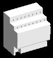
KNX line Energy flow LAN APPLICATION EXAMPLE
system Supply Energy sensor Heat Pump Smart Control Router Visu Pro Server IP interface 234 ENERGY SENSOR
Photovoltaic
Ref.-no.
KNX energy detector, 3-gang
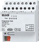
Rail mounting device, 4 rail units
ETS product family: Physical sensors
Product type: Energy detector
Product characteristics
2103 REG ES
The energy detector has three channels for connecting loads to up to three separate phases with a common neutral conductor. Each channel can measure:
• Voltage (eff.)
• Current (eff.)
• Active power
• Reactive power
Additionally, the active power and reactive power of all channels will be summed up and displayed as three-phase power values along with the mains frequency. According to the parameterisation the measured values will be transmitted on the KNX bus, either cyclically and / or when the value changes. An additional telegram will be transmitted if certain values exceed or fall below a specified limit.
The following meters exist for each channel and for the three-phase values:
• 1 x energy meter total
• 1 x energy meter ¼ h value
• 3 x energy meter (3 tarifs)
• 3 x energy intermediate meter (3 tarifs)
New in version 01
• Direct measurement (without transformer)
• Transformer measurement (with external 75 A transformer, ratio 75:5, e.g. Phoenix Contact order key 2277611)
Technical data
Power supply via E1/N
Rated voltage: AC 110 ... 240 V ~
Mains frequency: 50/60 Hz
Power consumption: max. 2 W
Inputs E1 ... E3
Rated voltage range: AC 110 ... 240 V ~
Rated current range: 4 mA ... 16 A
Rated frequency: 50/60 Hz
Measurands: voltage (rms value)
current (rms value)
frequency
active power (signed +/–)
reactive power (signed +/–)
active energy (signed +/–)
Pulses LED
Direct measurement
(without transformer): 6400 / kWh
Transformer measurement
(75 A transformer): 427 / kWh
Pulse duration: 4.9 ms
Power loss
Voltage measurement: ≤ 0.03 W / phase
Current measurement: ≤ 0.8 W / phase
Power consumption from mains: < 1 W
Connection
Connection mode: screw terminals
single wire: 1 x 0.5 ... 2.5 mm2
stranded without ferrule: 1 x 0.5 ... 2.5 mm2
stranded with ferrule: 1 x 0.5 ... 2.5 mm2
External transformer
Transformation ratio: 75:5
Secondary current: 0 ... 5 A
Accuracy
Direct measurement
(without transformer): 1 % of 200 mA ... 16 A
Transformer measurement
(75 A transformer, class 1): 2 % of 7.5 A ... 75 A
Ambient temperature: −5 ... +45 °C
Storage/transport temperature: −25 ... +70 °C
Mounting width: 72 mm (4 rail units)
KNX medium: TP 256
Rated voltage KNX: DC 21 ... 32 V SELV
Current consumption KNX: typical 10 mA
Connection, KNX: terminal
235 KNX Sensors
Universal Weather Station
GPS/GLONASS receiver for date/time and astro function
Brightness sensor for four directions; measurement of twilight and global radiation
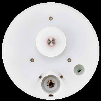
Precipitation sensor
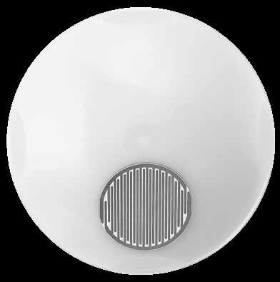
Wind speed, wind direction, brightness – in four directions, twilight, global radiation, precipitation, relative air humidity and air pressure are measured using the integrated sensors. The calculation of further data such as absolute humidity and perceived temperature is also carried out. Operating interdependently with each other, values are also determined in terms of the mugginess curve and comfort characteristic that can then be used to optimise the ventilation control. These features
Sensor for wind direction and wind speed
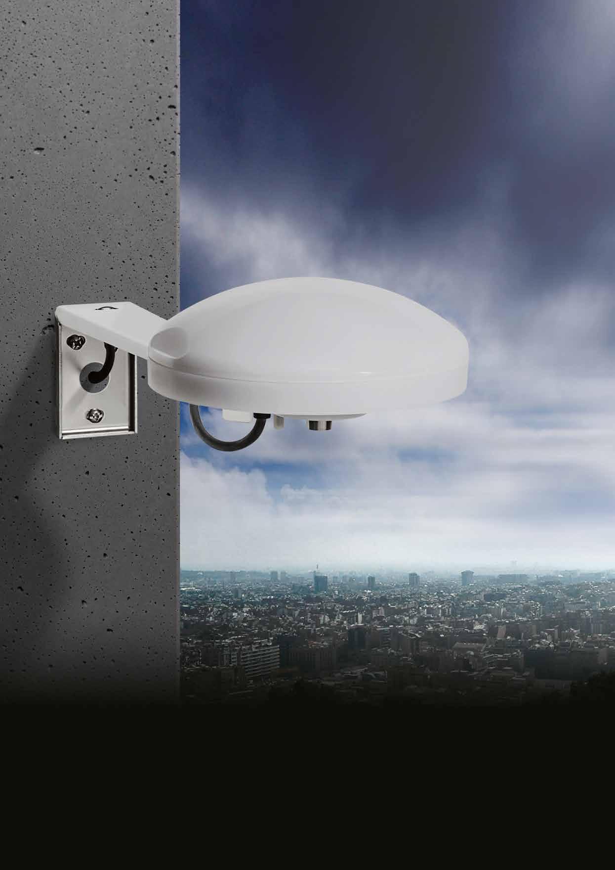
Temperature and dew point sensor
Humidity measurement
KNX bus coupling (supply 24 V AC/DC)
are enhanced with a GPS/GLONASS receiver for the date and time and an astro function for determining the position of the sun. This makes it no-longer necessary to set the time manually The installation of the weather station is carried out with its own fastening arm on the installation mast. This ensures the best capture and measurement of the weather data. The weather station can also be mounted onto the façade by means of the fastening arm.
All important sensors for recording and evaluation of meteorological data combined in compact design: the JUNG KNX Weather Station for weather-dependent automatic shading control for façade protection.
KNX Universal Weather Station
236 WEATHER STATION WEATHER STATION 237
Compact design, precise measurement
KNX Weather station
Ref.-no.
KNX universal weather station compact housing including fastening arm and connection cable
ETS product family: Physical sensors
Product type: Weather station
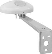
Intended use
2225 WS U
• Measurement and evaluation of weather data: wind speed, wind direction, precipitation, brightness, global radiation, twilight, temperature, relative air humidity and air pressure
• Installation on the outside of buildings, preferable in the roof and facade area
• Operation with additional power supply (ref.-no.: WSSV 10)
Product characteristics
• Integrated GPS/GLONASS receiver for automated positioning
• Calculation of additional weather data: absolute air humidity, chill temperature, comfort
• Function for shading control
• Integrated KNX bus coupling unit
• Measuring and limit value monitoring
• Software logic modules for linking events
• Integrated heating
The weather station needs an operating voltage supply of 24 V AC, for example power supply module ref.-no. WSSV 10.
Fastening arm (Spare part) for installation of the universal weather station, ref.-no.: 2225 WSU
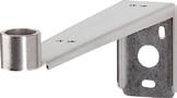
2225 BFA
Connection cable (Spare part) for universal weather station, ref.-no.: 2225 WSU
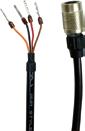
Technical data
Cable type: LiYCY 4xAWG26
Cable length: 5 m
2225 CAB
238
Technical data ref.-no. 2225 WS U
Power supply
Rated voltage: AC 24 V SELV (± 10 %) DC 21 ... 32 V SELV
Current consumption: 100 ... 400 mA (dependent on the weather)
Protection class: III
Cable type: LiYCY 4xAWG26
Cable length: 5 m
Total length per line: 15 m
Number of weather stations: max. 3 (per line)
KNX medium: TP 256
Rated voltage KNX: DC 21 ... 32 V SELV
Current consumption KNX: max. 5 mA
Ambient temperature: −30 ... +60 °C
Storage/transport temperature: −25 ... +70 °C
Protection level: IP 44 (in position for use)
Dimensions (Ø x H): 130 x 68 mm
Wind direction sensor
Measuring range: 1 ... 360°
Resolution: 1°
Accuracy: ± 10 % (laminar wind stream)
Wind speed sensor
Measuring range: approx. 0 ... 40 m/s
Resolution: 0.1 m/s
Accuracy (≤ 10 m/s): ± 1 m/s
Accuracy (> 10 m/s): ± 5 %
Temperature sensor
Measuring range: −30 ... +60 °C
Resolution: 0.1 K
Accuracy: ± 1 K (wind > 2 m/s, for −5 ... +25 °C)
Precipitation sensor
Measuring range: yes / no
Accuracy: fine drizzle
Brightness sensors
Number: 4
Measuring range: approx. 0 ... 150 klx
Resolution: 1 klx
Accuracy: ± 3 %
Spectral range: 475 ... 650 nm
Dawn sensor
Measuring range: approx. 0 ... 900 lx
Resolution: 1 lx
Accuracy: ± 10 lx
Air pressure sensor
Measuring range: 300 ... 1100 hPa
Resolution: 0.01 hPa
Accuracy: ± 0.5 hPa (20 °C)
Humidity sensor
Measuring range: 0 ... 100 % relative humidity (r. h.)
Resolution: 0.1 % relative humidity (r. h.)
Accuracy: ± 10 % rel. humidity (20 °C)
Absolute humidity: 0 ... 400 g/m3
Resolution: 0.01 g/m3
Global radiation
Measuring range: 0 ... 1300 W/m2
Resolution: 1 W/m2
Accuracy: ± 10 %
Spectral range: 350 ... 1100 nm
All accuracy specifications relate to the respective measuring range end value.
239 KNX
Weather station
KNX weather station "home"
Ref.-no.
2224 WH
The KNX weather station detects the meteorological data "Wind speed", "Precipitation", "Twilight", "Temperature" and the brightness in three directions. Its main area of application is the automatic, weather-dependent control of shading. It is specially designed for use in homes.
To increase functional reliability, the weather station monitors itself in some important functions, and reports any corresponding errors to the bus automatically via indicator objects. It is intended for outdoor installation on a mast or on a wall. The bus coupling to the KNX/EIB is integrated (monoblock).
Evaluation of the data themselves, in particular the limiting value processing, is performed already in the weather station.
A built-in heater protects against degradation of function from frost and moisture condensation down to –20 °C.
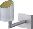
The heating system further ensures that the sensor surface of the precipitation sensor will dry off quickly after rain, and also melts snow and ice. Power is supplied to the unit via the bus, except for the heating system and the power supply for the precipitation sensor.
The weather station requires an external 24 V AC/DC power supply for the heating system, without which precipitation detection is not possible.
Logic gates are available for cascading a number of weather stations and for linking the limiting values and the monitoring functions. Blocking elements make it possible to block individual functions at the installation location.
Intended use
• Measurement and evaluation of weather data: wind speed, precipitation, twilight, temperature and brightness
• Vertical mounting on the outside of buildings, preferably on roofs and at façades
Product characteristics
• Integrated KNX bus coupling unit
• Compact housing
• Low-maintenance device
• Measured-value acquisition and limit value monitoring
The power supply ref.-no.: WSSV 10 is necessary for precipitation detection.
240
KNX Weather station
Technical data
KNX medium: TP 64
Rated voltage KNX: DC 21 ... 32 V SELV
Power consumption KNX: typical 450 mW
Connection, KNX: terminal
External power supply
Rated voltage: AC/DC 24 V SELV
Power consumption: typical 7.5 W
Connection: connecting terminal yellow/white
Ambient temperature: −20 ... 55 °C (free of ice and dirt)
Storing temperature: −40 ... +70 °C
Protection level: IP 44 (in position for use)
Protection class: III
Dimensions (W x H x D): approx. 88 x 170 x 204 mm (with assembly arm)
Weight: approx. 240 g
Sensor signals:
Temperature sensor
Measuring range: −20 ... +55 °C
Accuracy: ± 1 K (for wind speeds > 0.5 m/s)
Wind sensor
Measuring range: approx. 0 ... 40 m/s
Accuracy: ± 2 m/s
Precipitation sensor
Measuring range: precipitation yes / no
Sensitivity: fine drizzle
Switch-off delay: adjustable
Brightness sensor
Direction: east, south, west
Measuring range: approx. 1 ... 110 klx
Spectral range: approx. 700 ... 1050 nm
Accuracy: 10 % (of measuring range end value)
Dawn sensor
Direction: south
Measuring range: approx. 0 ... 674 lx
Spectral range: approx. 700 ... 1050 nm
Accuracy: 10 % (of measuring range end value)
Connection set for weather station home ref.-no.: 2224 WH for pole mounting 50 – 120 mm Ø

241 KNX
Weather station
MM 100
Ref.-no.
KNX Weather station
KNX analogue input, 4-gang
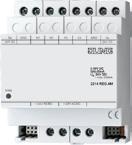
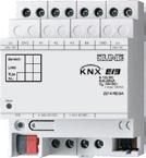
Rail mounting device, 4 rail units
ETS product family: Input
Product type: Analogue input 4-gang
The analogue input processes measured-value data supplied by analogue sensors. Four analogue transducers in any combination can be connected to the input. The analogue input evaluates voltage and current signals.
Voltage signals: 0 ... 1 V DC 0 ... 10 V DC
Current signals: 0 ... 20 mA DC 4 ... 20 mA DC
The 4 ... 20 mA current inputs can be monitored for open-circuit conditions. The analogue input needs a separate power supply, for example the power supply module ref.-no. WSSV 10.
Technical data
KNX medium: TP 256
Supply voltage: AC 24 V ~ ± 10 %
Analogue inputs: 4
Format: EIS 5 (2 Byte) or EIS 6 (1 Byte)
Ranges: voltage 0 ... 1 V, 0 ... 10 V; current 0 ... 20 mA, 4 ... 20 mA; depending on parameterisation
Limit values: 2 per channel
Supply output for sensor: 2 terminal pairs
Voltage: DC 24 V ± 25 %
Total current: max. 100 mA
Analogue input extension module, 4-gang
Rail mounting device, 4 rail units
extension module for analogue input
The analogue input extension module provides a KNX analogue input 2214 REG A with four additional sensor inputs. The evaluation of the measured data and the limiting values will be handled by the connected KNX device. The analogue input extension module evaluates voltage and current signals.
Voltage signals: 0 ... 1 V DC 0 ... 10 V DC
Current signals: 0 ... 20 mA DC 4 ... 20 mA DC
Technical data
External supply
Voltage: AC 24 V ~ ± 15 %
Current consumption: max. 170 mA (incl. sensors)
Analogue inputs: 4
Measuring ranges per channel
Voltage: 0 ... 1 V, 0 ... 5 V, 0 ... 10 V (DC)
Impedance approx. 18 kΩ
Current: 0 ... 20 mA, 4 ... 20 mA
Impedance approx. 100 kΩ
A/D converter: 14 Bit
Power supply for sensors: DC 24 V max. 100 mA
242
Ref.-no.
2214 REG A
2214 REGAM
Ref.-no.
Power supply AC 24 V ~ for universal weather station ref.-no.: 2225 WS U for weather station home ref.-no.: 2224 WH for analogue input ref.-no.: 2214 REG A for analogue actuator ref.-no.: 2204.01 REGA
Rail mounting device, 4 rail units
Intended use
• Supplying devices with 24 V AC
• Mounting on DIN rail according to EN 60715 in distribution boxes
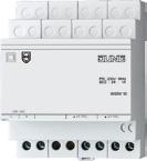
Product characteristics
• Two internally connected 24 V outputs
• Overload and short-circuit protection via thermo switch
Technical data
Rated voltage: AC 230 V ~, 50/60 Hz
Output current: max. 1 A
Output voltage: AC 24 V ~
Storage/transport temperature: −25 ... +70 °C
Ambient temperature: −5 ... +40 °C
Relative humidity: max. 93 % r. h., no condensation
Mounting width: 72 mm (4 rail units)
Connection: screw terminals single wire: 1 x 0.5 ... 4 mm2 stranded with ferrule: 1 x 0.14 ... 2.5 mm2 stranded without ferrule: 1 x 0.34 ... 4 mm2
Wind sensor
Intended use
• Sensor for measuring weather data
WSSV 10
WS 10 W
• Sensor signals are evaluated via additional electronics, e.g. analogue input (ref. no. 2214 REG A)
• Detection of the horizontal wind speed
• Vertical installation in outdoor areas, e.g. on walls of buildings, using the supplied mounting bracket
Product characteristics
• Measurement of the rotational speed of the anemometer
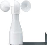
• Output with analogue output signal 0 ... 10 V
• Maintenance-free
• Operation without additional power supply possible
• To avoid dew and condensation, use a separate power supply (ref-no. WSSV 10) for heating
Technical data
Power supply
Rated voltage: DC 18 ... 32 V SELV
Current consumption: 6 ... 12 mA
Heating
Rated voltage: AC/DC 24 V
Switch-on current: max. 1 A
Ambient temperature: −25 ... +60 °C
Protection class: III
Protection level: IP 65 (in position for use)
Output signal
Measuring range: 0.9 ... 40 m/s
Strain: max. 60 m/s (for short periods)
Output voltage: DC 0 ... 10 V
Load: min. 1.5 kΩ
Cable type: LiYY 6 x 0.25 mm2
Cable length: approx. 3 m
can be extended up to: max. 100 m
Dimensions (Ø x H): 134 x 160 mm
243 KNX Weather station
KNX Weather station
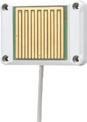
Ref.-no.
Rain sensor
Intended use
• Sensor for measuring weather data
WS 10 R
• Sensor signals are evaluated via additional electronics, e.g. analogue input (ref. no. 2214 REG A)
• Detection of precipitation
• Vertical installation in outdoor areas, e.g. on walls of buildings, using the supplied mounting bracket
Product characteristics
• Measurement of the electrical conductivity on the sensor surface
• Output using analogue output signal: 0 = dry, 10 V = rain
• Heating of the sensor surface with separate 24 V AC/DC power supply, ref.-no.: WSSV 10
Technical data
Power supply
Rated voltage: DC 15 ... 30 V
Current consumption: approx. 10 mA
Heating
Rated voltage: AC/DC 24 V
Power consumption: max. 4.5 W
Ambient temperature: −30 ... +70 °C
Protection class: III
Protection level: IP 65
Output signal
Output voltage: DC 0 / 10 V
Load: min. 1 kΩ
Reaction time: max. 4 min
Cable type: LiYY 5 x 0.25 mm2
Cable length: approx. 3 m can be extended up to: max. 100 m
Dimensions (W x H x D): 58 x 83 x 17 mm
244
Ref.-no.
Brightness sensor
Rated voltage 24 V DC range 0 ... 60 000 lux, linear
58 x 35 x 64 mm
WS 10 H
Dawn sensor
Rated voltage 24 V DC range 0 ... 255 lux, linear
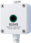
58 x 35 x 64 mm
WS 10 D
Temperature sensor
Rated voltage 24 V DC range –30 °C ... +70 °C, linear
58 x 35 x 64 mm
WS 10 T
The brightness sensor is used for the measuring and evaluation of the brightness. The dawn sensor is used for the measuring and evaluation of the brightness (dawn/dusk). The temperature sensor is used for the measuring and evaluation of the temperature. The value measured by the sensor is transmitted to an analogue output signal of 0 ... 10 V by the electronics.
Connections:
Plastic housing with PG7 thread + screw and pressure / moisture compensation (recommended cable 3 x 0.25 mm2)
+UB: operating voltage 24 V DC
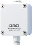
GND: corresponding ground
OUT: output 0 ... 10 V
Technical data
Supply voltage: DC 24 V (DC 15 ... 30 V)
Connection: screw terminals
Terminals for: 2.5 mm2
Connection cable: through screwed conduit entry PG 7
Recommended cable: 3 x 0,25 mm2
Cable length: max. 100 m
Output: 0 ... 10 V DC (into a load of at least 1 kΩ, short-circuit protected)
Ambient temperature: −30 ... +70 °C
Protection level: IP 65
Mounting position: optional
245 KNX Weather station
KNX signal panel
The KNX signal panel (MBT 2424) is ideal for use in supermarkets, shops and offices: The panel, with aluminium housing and high-quality glass front, has 24 independent, capacitive sensor buttons and 24 RGB LEDs for status display that are identified with foil strips. Alongside the switching/push-button, dimming, blind and scene functions, transducer functions are also possible. The LEDs can be separately parametrised and can light red, green or blue and thus, for example, indicate different states of the KNX system according to limit values. With a locking function, specific buttons, columns or
the complete panel can be locked. Acoustic signals for presses and as alarm signalling can be set. The MBT 2424 is installed in a flush-mounted, 2-gang wall box or in a surface-mounted installation housing and can be configured completely in the ETS. A drilling template is available for the installation. The identification of the functions allocated is done using replaceable labelling strips. Printing is done with the help of the JUNG printing tool. The front glass sheet is attached with four M3 snake-eye security screws. The bit required for installation is supplied.
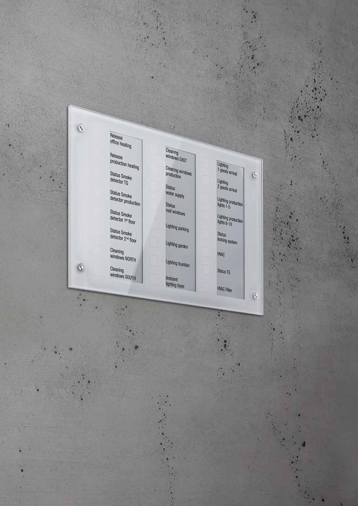
246 VISUALISATION/OPERATION
Signal panel
KNX signal panel
ETS product family: Display
Product type: Signal panel
glass green MBT 2424
glass white MBT 2424 WW
glass black MBT 2424 SW
Product characteristics
• Push-button functions switching, dimming, blind control, value transmitter, scene recall, etc.
• High quality glass surface with 24 sensor buttons
• Operation via touching the sensor buttons
• Labelling with exchangeable labelling foil
• Status indication with 24 LEDs; the colours red, green and blue can be configured
• Acoustical feedback for touching sensor
• Fault message on dismantling
• Logic and time functions
• Integrated bus coupling unit
• Supply via separate power supply (ref.-no. NT 2405 VDC) or the auxiliary voltage output of the KNX power supply
Technical data
External power supply
Rated voltage: AC/DC 24 V SELV
Power consumption: approx. 2.2 W
Connection, power supply: connecting terminal yellow/white single wire: 1 x 0.6 ... 0.8 mm2
Front plate (W x H x D): ca. 236 x 156 x 14 mm
Installation depth: approx. 39 mm
Ambient temperature: −20 ... +70 °C
Storage/transport temperature: −20 ... +75 °C
Relative humidity: 15 ... 95 % (no condensation)
Protection level: IP 54 flush-mounted IP 20 surface-mounted
Protection class: III
KNX medium: TP 256
Rated voltage KNX: DC 21 ... 32 V SELV
Connection, KNX: bus connection block Power consumption KNX: typical 150 mW
Surface-mounted housing for signal panel ref.-no.: MBT 2424 ..

light grey similar RAL 7035
Technical data
Dimensions: 236 x 156 x 52 mm (W x H x D)
Protection level: IP 20
Flush-mounted power supply for signal panel ref.-no.: MBT 2424 ..
EBG 2424
NT 2405 VDC
247 KNX
Ref.-no.
KNX Smart Panel
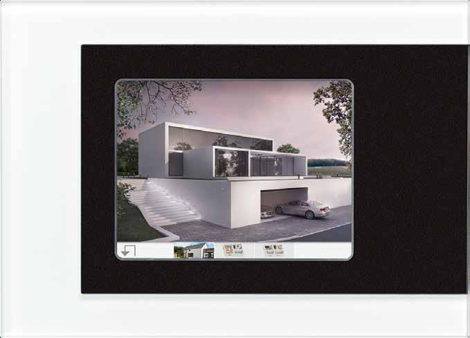
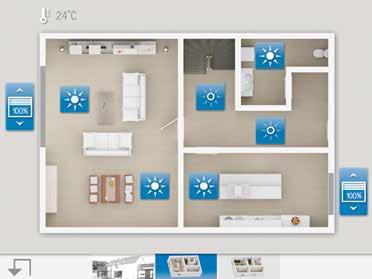
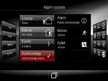
Operating comfort on 14.5 cm screen diagonal: Thanks to integrated control software, the functions are displayed and controlled using the colour TFT touch screen with the KNX Smart Panel 5.1.
JUNG USER INTERFACE
Visualisation and operation are performed using the uniform JUNG user interface that allows logical and intuitive operation of the various functions. This is generated quickly using the Smart Panel Designer as a planning tool.

FREELY CONFIGURABLE USER INTERFACE
As an alternative or in addition, a freely configurable user interface can be created. This enables the realisation of an individual display for the user.
Additional security is provided by the integrated alarm system in the Smart Panel for up to 40 detectors for interior and exterior perimeter protection. Additional functions are the 64-channel week timer with random and astro functions, the pre-configured lighting scene management, data logger for consumption data, limit value modules, and logic and time gates. These optimise the features and are quickly integrated.
KNX Smart Panel 5.1
© STEVE TROES FOTODESIGN VISUALISATION/OPERATION 249 248 VISUALISATION/OPERATION
KNX Smart Panel
Discontinued
Delivery capacity is ensured until May 2021.
Successor: SP 0081 U
KNX Smart Panel with integrated BCU aspect ratio 4:3 for installation in walls, touch screen fanless, without rotating parts
Intended use
Technical data
Power supply
Rated voltage:
Ref.-no.
• Operation and visualisation of system statuses and information on building automation • Flush-mounted fitting indoors
Product characteristics
• Illuminated graphic colour screen TFT, 640 x 480 pixels, 262 000 colours • Touchscreen • KNX Interface
• Interfaces – accessible from front: 1 x USB 2.0 • Interfaces – accessible from behind: Ethernet • Graphical user interface for visualisation and operation of KNX devices • Predefined graphical user interface • Free graphical user interface • KNX special functions, e.g. scenes, forced position, timer, presence simulation
• Fast access to pages and functions • Remote access (remote function)
• Combination of predefined and free graphical user interface
• Free pages: max. 50 • Elements: max. 400
• 240 functions, e.g.:
– Scene recalls: max. 40
• Master pages: max. 10
• Acoustic signal encoder, configurable
• Copy & Paste functions • 50 rooms • 10 function units
– Signalling system: max. 40 detectors (internal and external skin together)
– Datalogger: max. 20 datalogger channels
– Logic gates: max. 80 gates with up to 8 inputs and one output each
– Timers: max. 40
– Limiting value modules: max. 40
– Demultiplexer "1 to 2" and "1 to 4": max. of 7 each
– Timer: max. 64 switching channels with a total of 128 switching times
– Scenes: max. of 24 scenes, max. of 32 scene functions
– Presence simulation: max. 8 simulations, max. 32 functions (15 functions per simulation)
– Fault messages: max. 50
– Event e-mails: max. 50
– Video messages: max. 8
– System time: max. 40
USB
AC 230 V ~, 50/60 Hz
Current consumption: max. 100 mA
Fine-wire fuse: Littelfuse/Wickmann 372 1160
T 1.6 L 250
Power consumption (Display off): approx. 2.5 W
Power consumption: max. 11.5 W
Typical power consumption
(40 % brightness): 4.5 W
Ambient conditions
Ambient temperature: 0 ... +40 °C
Storage/transport temperature: −10 ... +70 °C
Relative humidity: 15 ... 85 % (no condensation)
Protection class: II
Screen diagonal: 145 mm / 5.7’’
Resolution: VGA (640 x 480)
Colours: 262,000
Viewing angle horizontal: ± 70°
Viewing angle vertical: ± 60°
Touchscreen: resistive
USB version: 2.0
Connection: 1 x type A
Network Type: 10/100/1000 Mbit/s Ethernet
Connection: RJ45 socket8/4-pin
Dimensions (W x H x D), without design frame 220 x 140 x 48 mm
Dimensions screen (W x H): approx. 115 x 86.5 mm
KNX medium: TP 256
Rated voltage KNX: DC 21 ... 32 V SELV
Power consumption KNX: typical 150 mW
Connection, KNX: terminal
250
SP 5.1 KNX
Frame for Smart Panel ref.-no.: SP 5.1 KNX
white
black
aluminium
Dimension: 236 x 170 x 8 mm (W x H x D)
Acrylic glass with printed rear side
Smart Panel
R 5 WW
R 5 SW
R 5 AL
Frame for Smart Panel ref.-no.: SP 5.1 KNX
aluminium
stainless steel
Dimension: 236 x 170 x 10 mm (W x H x D)
FP AL 781
FP ES 781
Glass frame for Smart Panel ref.-no.: SP 5.1 KNX


glass green
glass white
glass black
Dimension: 236 x 170 x 10 mm (W x H x D)
safety glass acc. DIN 1249
Frame for Smart Panel ref.-no.: SP 5.1 KNX
aluminium
white (aluminium lacquered)
Dimension: 232 x 152 x 7 mm (W x H x D)
FP GLAS 781
FP GLAS 781 WW
FP GLAS 781 SW
R 5 AL E
R 5 WW E
Frame for Smart Panel ref.-no.: SP 5.1 KNX industrial version
anthracite
Dimension: 236 x 170 x 6 mm (W x H x D)
FPI 781 AN
Flush-mounted recessed box for Smart Panel ref.-no.: SP 5.1 KNX cut-out dimensions (W x H): 212 x 124 mm


installation depth: 75 mm
can also be used for hollow wall mounting
EBG 24
251
KNX
Ref.-no.
R 5 WW
FP AL 781
FP GLAS 781
R 5 WW E
FPI 781 AN
Smart Controls
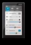
Multifunctional control panels for smart buildings: The Smart Controls take over the control and visualisation of various systems for building automation using apps. Thanks to the JUNG Launcher, all available applications are clearly displayed and can be called up directly by tapping on the respective icon. The control panels in the Smart Control family are available in various sizes and designs, depending on space available and intended use. The seven-inch version can be mounted vertically if desired. The Smart Control 5 with vertical display allows installation in a deep standard wall box due to its compact design.
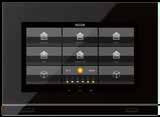
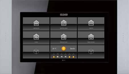

The Smart Controls for wall mounting are available in various sizes as required.
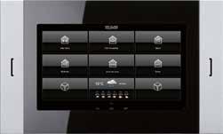
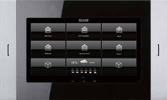

Smart Control 19
VARIANTS Smart Control 10 256mm / 10.1" Smart Control 7 178mm / 7" Smart Control 5 127mm / 5" Smart Control 19 470mm / 18.5" Smart Control 15 396mm / 15.6" 252 VISUALISATION/OPERATION VISUALISATION/OPERATION 253


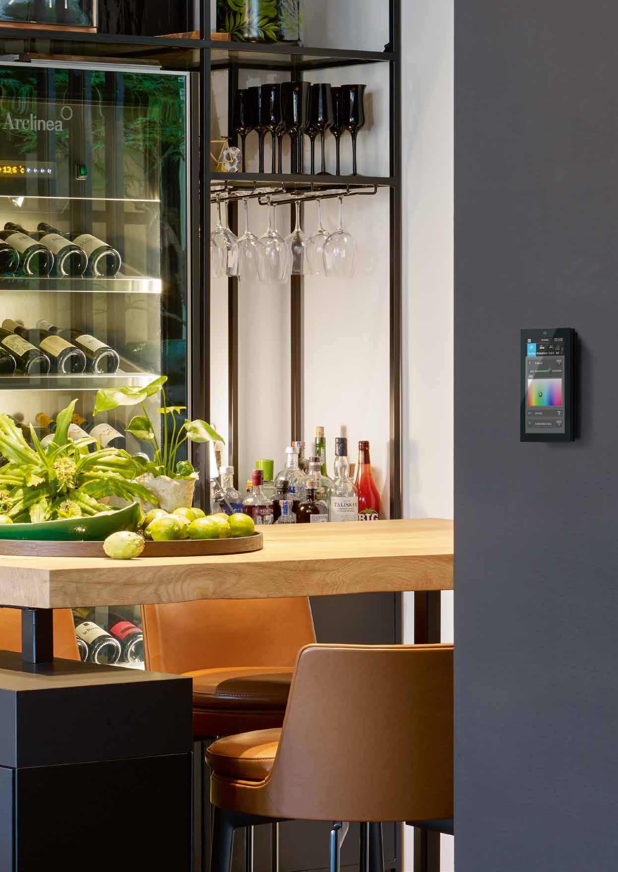

Smart Controls Smart Control 19 Smart Control 15 Smart Control 10 Smart Control 7 Smart Control 5 Mobile devices Access your Smart Home with a smartphone or tablet? No problem thanks to apps and myJUNG. eNet Server Visu Pro Server Visu Pro Server Hotel Edition Visu Pro Server Senec Edition
the Smart Controls, KNX and eNet SMART HOME installations and door intercom functions can be operated using only one device, including in parallel. In combination with various system servers, all settings and functions
controlled using the apps via Launcher. Thereby, options for use in private as well as commercial construction can be selected. Smart Visu Server Door communication amazon alexa amazon alexa amazon alexa amazon alexa amazon alexa VISUALISATION/OPERATION 255 254 VISUALISATION/OPERATION
Server and clients
With
are then conveniently
Compact design
Thanks to a slim, compact design, the SC 5 fits into a deep wall box. With the high-resolution touch display, the functions can be conveniently operated.
With a high-resolution touch display, users operate all functions conveniently and intuitively. The high-resolution graphic display is reminiscent of the newest smartphones in respect of its appearance, brightness of the colours and sharpness. With an integrated proximity sensor, the display wakes up from standby mode when the user wants to operate it. A brightness sensor automatically
adapts the display brightness to the current light conditions in the room. With the preinstalled apps for the “JUNG Visu Pro” visualisation server, “Smart Visu Server” and “eNet Server”, the operation of the building technology is made simply convenient. Using the combination with the Siedle Smart Gateways, the connection to the door communication can be implemented as normal.

EASY INSTALLATION
81
132
127
The Smart Control 5 fits every standard flush-mounted box.
mm
mm
mm/5"
256 VISUALISATION/OPERATION
Ref.-no.
Smart Control 5 for installation in walls, capacitive touch screen fanless, without rotating parts
black SC 5 SW
Intended use
• Visualisation and operation of system statuses and information on building automation
• For vertical installation
• Installation in flush box according to DIN 49073
• Ensure correct orientation when installing the appliance box. Mounting screws must be in vertical alignment.
Product characteristics
• KNX visualisation in combination with Visu Pro Server (ref.-no.: JVP-SERVER-H2)
• KNX visualisation in combination with Smart Visu Server (ref.-no.: SV-SERVER-INT)
• eNet visualisation in combination with eNet server for rail mounting (ref.-no.: ENET-SERVER) with software version 2.2 or higher
• Door call function only in combination with Siedle Smart Gateway SG 650-.. or SG 150-..
• High performance HD screen
• Proximity sensor
• Graphical user interface
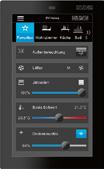
• Brightness level of display adapts automatically to ambient brightness
• Smart Gateway with integrated image storage
Technical data
Rated voltage: DC 24 V SELV
Rated capacity: < 1.5 W
Screen diagonal: 127 mm / 5’’
Resolution: 720 x 1280
Frame dimensions (W x H): 81 x 132 mm
Power supply: PoE acc. to IEEE 802.3af or DC 24 V via external power supply (ref.-no. NT 2415 REG VDC, not included)
Processor: Cortex-A53
Loudspeaker: integrated
Microphone: integrated
LAN connections: 1 x 10/100 Mbit/s
Ambient temperature: 0 ... +30 °C
SV-Server set Smart Control 5 consists of Smart Visu Server (ref.-no.: SV-SERVER-..) and Smart Control 5 (ref.-no.: SC 5 SW) black SV-S-SC 5 SW
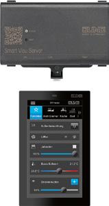
257 KNX Smart Control
KNX Smart Control
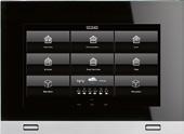
Ref.-no.
Smart Control 7 aspect ratio 16:9 for installation in walls, capacitive touch screen fanless, without rotating parts
aluminium SC 7.1 AL black SC 7.1 SW
Intended use
• Visualisation and operation of system statuses and information on building automation
• For vertical or horizontal installation
• Mounting in flush-mounted recessed box Product characteristics
• KNX visualisation in combination with Visu Pro Server (ref.-no.: JVP-SERVER-H2)
• KNX visualisation in combination with Smart Visu Server (ref.-no.: SV-SERVER-INT)
• eNet visualisation in combination with eNet server for rail mounting (ref.-no.: ENET-SERVER) with software version 2.2 or higher
• Door call function only in combination with Siedle Smart Gateway SG 650-.. or SG 150-..
• Pre-installed weather page
• Display of up to six IP camera images
• Cleaning function
• Smart Gateway with integrated image storage Please check Release Notes.
Technical data
Screen diagonal: 178 mm / 7’’
Resolution: WSVGA (1024 x 600), LED backlight display
Frame dimensions (W x H): 206 x 150 mm
Power consumption: max. 7 W
Power supply: PoE+ acc. to IEEE 802.3at, with Cat5e/Cat6 cable, length max. 100 m or DC 12 ... 32 V via external power supply (ref.-no. NT 2415 REG VDC, not included)
Operating system: Android 6
Processor: Cortex-A53
Main memory: 2 GB
Mass storage: 16 GB Flash (available disc space depends on operating system)
Loudspeaker: integrated
Microphone: integrated
USB ports: 2 x USB 2.0
1 x Mini-USB OTG
LAN connections: 1 x 10/100/1000 Mbit/s
Ambient temperature: 0 ... +30 °C
Flush-mounted recessed box for Smart Control ref.-no.: SC 7.1 ..
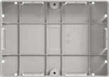
cut-out dimensions (W x H): 202 x 141 mm installation depth: 67 mm
SC 7 EBG
Power supply for rail mounting for Smart Control ref.-no.: SC 5 SW, SC 7.1 .., SC 10.1, SC 15.1, SC 19.1
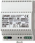
Rail mounting device, 4 rail units
NT 2415 REG VDC
258
Ref.-no.
Smart Control 10 aspect ratio 16:9 for installation in walls, capacitive touch screen fanless, without rotating parts
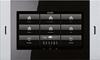
25.6 cm – 10.1’’
Intended use
SC 10.1
• Visualisation and operation of system statuses and information on building automation
• For horizontal installation
• Mounting in flush-mounted recessed box
Product characteristics
• KNX visualisation in combination with Visu Pro Server (ref.-no.: JVP-SERVER-H2)
• KNX visualisation in combination with Smart Visu Server (ref.-no.: SV-SERVER-INT)
• eNet visualisation in combination with eNet server for rail mounting (ref.-no.: ENET-SERVER) with software version 2.2 or higher
• Door call function only in combination with Siedle Smart Gateway SG 650-.. or SG 150-..
• Pre-installed weather page
• Display of up to six IP camera images
• Cleaning function
• Smart Gateway with integrated image storage
Please check Release Notes.
Technical data
Screen diagonal: 256 mm / 10.1’’
Resolution: WSVGA (1024 x 600), LED backlight display
Frame dimensions (W x H): 333 x 200 mm
Power consumption: max. 16 W
Power supply: PoE+ acc. to IEEE 802.3at, with Cat5e/Cat6 cable, length max. 100 m or DC 12 ... 32 V via external power supply (ref.-no. NT 2415 REG VDC, not included)
Operating system: Android 6
Processor: Cortex-A53
Main memory:
2 GB
16 GB Flash (available disc space depends on operating system) Slot of memory card: microSD
Mass storage:
Loudspeaker: integrated
Microphone: integrated
USB ports:
2 x USB 2.0
1 x Mini-USB OTG (accessible from the front)
LAN connections: 1 x 10/100/1000 Mbit/s
Ambient temperature: 0 ... +30 °C
Flush-mounted recessed box for Smart Control ref.-no.: SC 10.1

cut-out dimensions (W x H): 315 x 182 mm
installation depth: 80 mm
profile height: approx. 17 mm
Flush-mounted recessed box, flat version for Smart Control ref.-no.: SC 10.1
cut-out dimensions (W x H): 329 x 196 mm
installation depth: 82 mm
profile height: approx. 3 mm
SC 10 EBG
Installation note: Due to the small overlap, the wall cut-outs must be processed very accurately. No additional power supplies may be installed in the installation box.
259 KNX Smart Control
N SC 10 EBGF
KNX Smart Control
Ref.-no.
Smart Control 15 aspect ratio 16:9 for installation in walls, capacitive touch screen fanless, without rotating parts
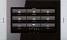
39.6 cm – 15.6’’
Intended use
SC 15.1
• Visualisation and operation of system statuses and information on building automation
• For horizontal installation
• Mounting in flush-mounted recessed box
Product characteristics
• KNX visualisation in combination with Visu Pro Server (ref.-no.: JVP-SERVER-H2)
• KNX visualisation in combination with Smart Visu Server (ref.-no.: SV-SERVER-INT)
• eNet visualisation in combination with eNet server for rail mounting (ref.-no.: ENET-SERVER) with software version 2.2 or higher
• Door call function only in combination with Siedle Smart Gateway SG 650-.. or SG 150-..
• Pre-installed weather page
• Display of up to six IP camera images
• Cleaning function
• Smart Gateway with integrated image storage
Please check Release Notes.
Technical data
Screen diagonal: 396 mm / 15.6’’
Resolution: WXGA (1366 x 768), LED backlight display
Frame dimensions (W x H): 510 x 306 mm

Power consumption: max. 25 W
Power supply: PoE+ acc. to IEEE 802.3at, with Cat5e/Cat6 cable, length max. 100 m or DC 12 ... 32 V via external power supply (ref.-no. NT 2415 REG VDC, not included)
Operating system: Android 6
Processor: Cortex-A53
Main memory: 2 GB
Mass storage: 16 GB Flash (available disc space depends on operating system)
Slot of memory card: microSD
Loudspeaker: integrated
Microphone: integrated
USB ports: 2 x USB 2.0
1 x Mini-USB OTG (accessible from the front)
LAN connections: 1 x 10/100/1000 Mbit/s
Ambient temperature: 0 ... +30 °C
Flush-mounted recessed box for Smart Control ref.-no.: SC 15.1
cut-out dimensions (W x H): 492 x 288 mm
installation depth: 80 mm profile height: approx. 17 mm
Flush-mounted recessed box, flat version for Smart Control ref.-no.: SC 15.1
cut-out dimensions (W x H): 506 x 302 mm
installation depth: 82 mm
profile height: approx. 3 mm
SC 15 EBG
Installation note: Due to the small overlap, the wall cut-outs must be processed very accurately. No additional power supplies may be installed in the installation box.
260
15
N SC
EBGF
Ref.-no.
Smart Control 19 aspect ratio 16:9 for installation in walls, capacitive touch screen fanless, without rotating parts
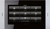
47 cm – 18.5’’
Intended use
SC 19.1
• Visualisation and operation of system statuses and information on building automation • For horizontal installation • Mounting in flush-mounted recessed box
Product characteristics
• KNX visualisation in combination with Visu Pro Server (ref.-no.: JVP-SERVER-H2) • KNX visualisation in combination with Smart Visu Server (ref.-no.: SV-SERVER-INT) • eNet visualisation in combination with eNet server for rail mounting (ref.-no.: ENET-SERVER) with software version 2.2 or higher • Door call function only in combination with Siedle Smart Gateway SG 650-.. or SG 150-.. • Pre-installed weather page • Display of up to six IP camera images • Cleaning function • Smart Gateway with integrated image storage
Please check Release Notes.
Technical data
Screen diagonal: 470 mm / 18.5’’
Resolution: WXGA (1366 x 768), LED backlight display
Frame dimensions (W x H): 600 x 345 mm
Power consumption: max. 30 W
Power supply: DC 12 ... 32 V via external power supply (ref.-no. NT 2415 REG VDC, not included)
Operating system: Android 6
Processor: Cortex-A53
Main memory:
Mass storage:
2 GB
16 GB Flash (available disc space depends on operating system)
Slot of memory card: microSD
Loudspeaker: integrated
Microphone: integrated
USB ports:
2 x USB 2.0
1 x Mini-USB OTG (accessible from the front)
LAN connections: 1 x 10/100/1000 Mbit/s
Ambient temperature: 0 ... +30 °C
Flush-mounted recessed box for Smart Control ref.-no.: SC 19.1
cut-out dimensions (W x H): 582 x 327 mm
installation depth: 80 mm
profile height: approx. 17 mm
Flush-mounted recessed box, flat version for Smart Control ref.-no.: SC 19.1
cut-out dimensions (W x H): 596 x 341 mm
installation depth: 82 mm
profile height: approx. 3 mm
Installation note: Due to the small overlap, the wall cut-outs must be processed very accurately. No additional power supplies may be installed in the installation box.
Power supply for rail mounting for Smart Control ref.-no.: SC 5 SW, SC 7.1 .., SC 10.1, SC 15.1, SC 19.1
Rail mounting device, 4 rail units
261 KNX Smart Control
NT
REG VDC
2415
SC 19 EBG
N SC 19 EBGF
Simply live smarter
Intelligent, easy, secure: the Smart Visu Server visualises KNX processes on smartphones, tablets and touch displays. Users can use it to integrate existing building technology into smart KNX technology, make intelligent building control more convenient and operate it using their voice.
The nerve centre of a Smart Home
LIGHT
Dimmed or brightly lit: the Smart Visu Server allows comprehensive lighting control using KNX and is additionally compatible with Philips Hue.
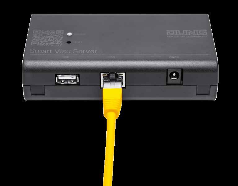
BLINDS AND SHUTTERS
Shading is easy to provide – selectively per room or on complete floors at the same time. Manually, automatically or timer controlled.
HEATING
Occupiers of a Smart Home enjoy constant feel-good temperatures. Thanks to remote access to the Smart Visu Server they can pre-warm the home while still travelling.
PRESENCE SIMULATION
Dynamic, automated living-room light or external lighting controlled remotely: thanks to the Smart Visu Server, the house always looks occupied.
SCENES
With the press of a button, create your preferred mood. Blinds move down to provide shade and at the same time the lighting is individually dimmed.
When the occupiers come home in the evening, the heating has already ensured a warm living room. Beyond that, the JUNG Smart Visu Server provides even more convenience and control, as many processes run automatically in a KNX system. It visualises
ENTERTAINMENT
The server supports the integration of the Sonos sound system. As a result the volume can even be controlled with a rotary sensor on the wall.
and precisely controls these smart processes. Together with the app, users can control many functions with a smartphone, tablet or by voice. The light isn’t optimal in the living room? Then adapt the lighting to your requirements – conveniently from the sofa.
SERVER
SMART VISU
SMART VISU SERVER 263 262 SMART VISU SERVER
For wall or DIN rail mounting
Intuitive control according to your wishes
MANUALLY
Switching and dimming light, controlling blinds or shutters, storing light scenes and much more: with the JUNG KNX push-button sensors, users can control the intelligent building technology conveniently with the press of a button. With clear symbols, the function assignment is self-explanatory. You can change reserved push-buttons for scenes quickly and easily using the Smart Visu Server.
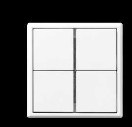
VOICE CONTROL
Control modern building technology intelligently – that is the strength of the Smart Visu Server in a KNX system. In conjunction with a smart speaker from Amazon or Google, JUNG makes it possible to control the sub-systems by voice. Once integrated, Alexa or Google Assistant receive the commands of the Smart Home occupier.
SMART VISU SERVER APP
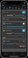
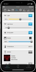

At home or on the move: with the Smart Visu Server app, users can control all Smart Visu Server functions. The app is available for iOS and Android. The access from outside the home network uses a myJUNG account with secure remote access. Additionally, the app is responsive: the display is impressive both on a smartphone and a tablet.
SONOS
Using the connection to the Sonos sound system, users hear their favourite music everywhere. Furthermore, they can also configure their personal settings using the Smart Visu Server, such as the volume, their saved playlists and much more. With building functions joined up and combined into actions, their own party mode is created.
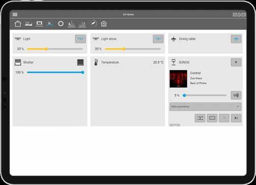
PHILIPS HUE
The Smart Visu Server detects a Philips Hue Bridge as soon as it is installed in the network. All lights linked to it then become visible in the Smart Visu Server app user interface. Using SV Control (the configuration area), the users can link the individual light sources with their favourites: in this way they can quickly and easily control the light. With rotary sensor, push-button sensors or with an app.
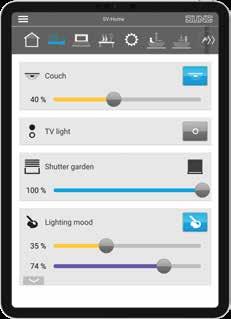
OPTIMUM VIEW ON ALL END DEVICES

SV-Home is the user interface of the JUNG Smart Visu Server. Well organised, it shows all the possibilities around the home, simply and clearly. Users can immediately see all states in the Smart Home and individually control the functions.
In the JUNG KNX system, components such as Philips Hue, Sonos, Amazon Echo and much more are unified by the Smart Visu Server.
Strong TV sound in the living room, a relaxed radio play in the bedroom and jazz in the kitchen: everything completely according to individual wishes.
VISUALISATION/OPERATION 265 264 VISUALISATION/OPERATION
Flexible configuration
The Smart Visu Server is integrated into the home network via the router. The installation is accomplished quickly with ETS Import, and the system is always current thanks to updates.
ETS IMPORT
An existing KNX installation is imported directly from the ETS using an OPC file. The group addresses are presented in a sortable list for an optimum overview and simple allocation. The integration of the existing technology is thus accomplished quickly and easily.
Numerous sources of assistance
JUNG offers extensive additional information online: From instructions to webinars, everything to do with the Smart Visu Server is available at jung.de/svs.
JUNG WEB SITE
On the JUNG web site you can find all the information on the Smart Visu Server, including brochures, pictures and press articles to download. Clearly presented and illustrated. Naturally also with further links. JUNG.DE/SVS
QUICK START GUIDES
Integrating voice control with Alexa and Google Assistant, setting up remote access or creating a presence simulation: the JUNG Quick Start Guides are free PDFs and provide comprehensive help for the Smart Visu Server.
USER MANAGEMENT
Everything configured and the customer is happy? Then it is time for the handover: In the control area of the Smart Visu Server, system integrators specify roles, allocate passwords and decide which user roles can or would like to edit which functions.
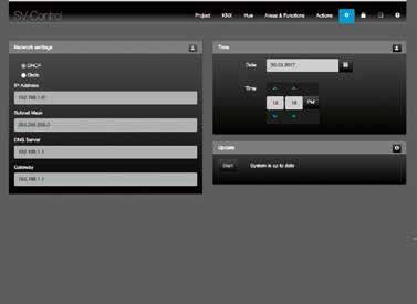
UPDATE CAPABILITY KEEPS THE SYSTEM CURRENT
New features and continuous improvements: JUNG works continuously on new upgrades for the Smart Visu Server. As soon as a new version is available, the update is available in the SV Control area. All updates are summarised chronologically in the “Change log” and are available to download at jung.de/svs.
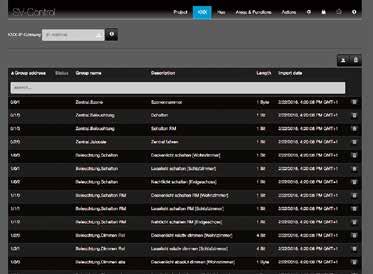
VIDEO TUTORIALS
On the JUNG web site you can find the video tutorials that make the integration and installation of the Smart Visu Server easier. Here you can find out everything about commissioning, configuration, system maintenance and updates.
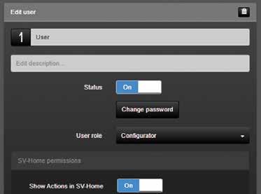
WEBINARS
In the interactive webinars, JUNG provides everything worth knowing, including about the Smart Visu Server. Participation is free and there is the possibility during the webinar to ask the JUNG training team questions.
JUNG ONLINE CATALOGUE
The individual items have technical information attached in the JUNG online catalogue that can be viewed and downloaded. You can find operating instructions, tender texts, datasheets, product documentation and more with a mouse click using the Info button.
VISUALISATION/OPERATION 267 266 VISUALISATION/OPERATION
Smart Visu Server
Ref.-no.
Smart Visu Server with mounting plate for wall or rail mounting installation including plug-in power supply
with Europlug
SV-SERVER including adapter for UK and China
SV-SERVER-INT
Intended use
• Visualisation and operation of KNX systems via devices with HTML5 browser or app (iOS, Android), e.g. Smart Control (ref.-no.: SC 5 SW, SC 7.1 .., SC 10.1, SC 15.1, SC 19.1), smartphone, tablet, laptop, PC, etc.
• Visualisation and operation of Philips Hue systems
• Operation in local IP networks that support DHCP (Dynamic Host Configuration Protocol), or with static IP address (IPv4)
• Operation indoors
Product characteristics
• Web visualisation of KNX system for status indication and operation (SV-Home)
• Access from max. 10 different clients to SV-Home recommended
• Integrated web-based commissioning tool (SV-Control)
• Easy to create a pre-configured user interface, optimised for domestic applications and small commercial facilities
• Graphical control elements: symbols can be selected from supplied libraries
• Import of group addresses (three-stage) via OPC import (ETS3, ETS4, ETS5)
• Manual input of group addresses possible
• 24 areas
• 240 dynamic functions (max. 1200 data points)
• 25 action groups
• 250 configurable actions (max. 16 functions per action)
– Customised
– Switching times
– Status logic
– Depending on events
– Astro
• Connection to KNX bus via KNX IP router (ref.-no. IPR 200 REG, IPR 300 SREG), KNX IP interface (ref.-no. IPS 200 REG, IPS 300 SREG) or power supply with IP interface (ref-no. 20320 1S IPS R)
• Integration of Philips Hue systems in the KNX installation
• Connection to Philips Hue via Philips Hue Bridge
• Integration of SONOS loudspeakers in the KNX installation
• Integration of Amazon Alexa voice control via MyJUNG account
• Integration of Google Home voice control via MyJUNG account
• Secure remote access via MyJUNG account
• Update and upgrade compatible
268
KNX
Technical data ref.-no. SV-SERVER...
Rated voltage: DC 12 V SELV
Power consumption: typical 3 W, max. 7 W
Ambient temperature: −5 ... +45 °C
Storage/transport temperature: −25 ... +70 °C
LAN: RJ45-socket (10/100 Mbit/s Fast Ethernet)
USB: USB 2.0 Host
Dimensions: 124 x 72 x 31 mm (without mounting plate) 124 x 92 x 40 mm (with mounting plate)
Plug-in power supply
Primary voltage: AC 100 ... 240 V ~
Mains frequency: 50/60 Hz
Rated current: max. 1 A
Secondary voltage: DC 12 V SELV
Protection class: II
Length of connected cable: 1.5 m
Smart Visu Server remote access licence

Remote access to the building technology via JUNG server in Germany.
269
KNX Smart Visu Server Ref.-no.
unlimited N SV-SERVER-L
JUNG Visu Pro
Overview of function modules:
PROCESS MODEL
The process model is the logical core of the system. Here the function modules, the so-called process connections, are connected internally. Dependencies, complex processes and logic, as well as time functions or scenes can be defined here. In the same way, data can be archived and presented using various diagrams.
Compact, secure, versatile: JUNG Visu Pro visualises the KNX system in the smart building using end devices with an HTML5-capable browser or the app. Connected with the KNX installation and the local network, it makes comprehensive individual adaptations of the complete system possible.
The JUNG Visu Pro software is a flexible system without data point limits and is thus also perfectly suited to complex applications, whether in the private or trade field. Particularly the option to include multiple independent KNX systems parallel in one process model via
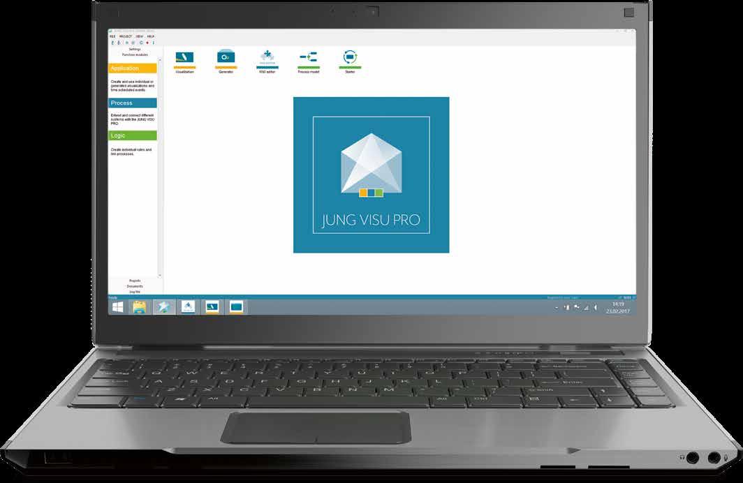
KNXnet/IP protocol creates comprehensive possibilities for property-spanning projects. The Visu Pro software can be displayed on all HTML5-capable browsers, and naturally also using mobile end devices. Voice control provides even more convenience.
VISUALISATION EDITOR
The visualisations are created here using individual worksheets. The controls can be placed and individualised completely freely. Alongside form factor, the transparency and inscriptions can be set in addition. Personal background images can likewise be used and individual symbols imported.
KNX EDITOR

This function module establishes the connection to the KNX installation. The system supports the latest communication standards in accordance with KNX Secure. For large projects, the KNX Multieditor is available. This extension of the KNX Editor allows the operation of up to 150 parallel KNX tunnel connections.

DEVICE EDITOR

System integrators can implement the widest range of special applications here. Numerous applications, for example for working with the JUNG KNX DALI gateway or an online weather service, are supplied. Based on the LUA scripting language, the specialist can develop individual process connections and thus extend the JUNG Visu Pro software with individual functions.
SMART ASSISTANT

To save time and to support project planning: this free additional tool minimises the production effort required with automatically generated worksheets for the visualisation. System integrators can quickly create user interfaces, structures and templates and apply to the JUNG Visu Pro software.

VISUALISATION/OPERATION 271 270 VISUALISATION/OPERATION
JUNG Visu Pro software
From the planner version for pre-planning to the full version for hotels: JUNG offers the appropriate Visu Pro software for all applications.
Voice control for the smart home or the configuration of access control in smart hotels: with the planner version, system integrators can completely configure and set up every customer system in advance – independently of the hardware required later. The final porting to the customer system follows only when all requirements have been finally decided For entering the home area, the JUNG Visu Pro server is appropriate. For particularly complex KNX systems, on the one hand inte-
grators turn to a full version of JUNG Visu Pro (JUNG Visu Pro full version or JUNG Visu Pro Hotel). On the other hand, they need a tailored hardware solution in order to implement their individual KNX building system. Regular updates keep all systems constantly up-to-date. As soon as a new version is available, the update is available as a download in the JUNG online catalogue. Documentation of all changes made is listed in the “Change log” document, which is available in the myJUNG area.
Application examples
“Alexa, switch on the light”. Or: “Hey, Google. Set the temperature in the living room to 24 degrees”. The JUNG Visu Pro Server is compatible with both
the Alexa and Google Assistant voice services. KNX in the smart home is versatile and flexible with the JUNG Visu Pro.
JUNG Visu Pro Server – numerous interfaces to other systems
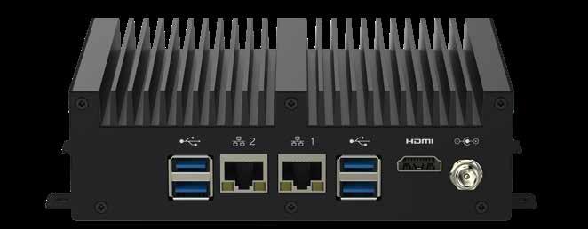
VOICE CONTROL
JUNG Visu Pro combines modern and future-proof smarthome technology with particularly convenient control –the JUNG Visu Pro Server allows the voice control of all subsystems. All residents need is the Visu Pro Server and a smart speaker from Google or Amazon: Once integrated, Alexa or the Google Assistant are available for voice control.
INTUITIVE OPERATION
KNX installations with individual adaptations can be displayed and controlled using JUNG Visu Pro. As a result of consistent use of HTML5 pages, the desired visualisation can be displayed on all JUNG smart controls, tablets or smartphones. Practical templates for the user interface can be adapted completely individually. Since the update to version 4.6, JUNG Visu Pro supports a day and night mode.
VISU PRO REMOTE ACCESS

The whole JUNG Visu Pro system naturally supports remote access (JVP Remote) to the building technology. With the remote access for Jung Visu Pro, users of the KNX installation can visualise, control and adapt their KNX system to their requirements at any time and from any location. Since the update to version 4.6, multiple people can access the system simultaneously. The servers are located in Germany.
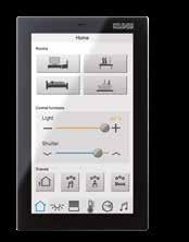
HDMI™
DC 12 V USB 3.0 USB 3.0 2 x LAN
The JUNG Visu Pro Server is the compact solution for controlling building automation in conjunction with the pre-installed Visu Pro software. Ideal for applications in challenging private construction.
connection
VISUALISATION/OPERATION 273 272 VISUALISATION/OPERATION
KNX in the hotel sector
LINK
Use in hotels
The front office works with the familiar user interfaces. In the background, hotel and control software are connected with each other. Pre-set profiles are activated directly at check-in and the wishes of the guest reach the personnel via notification on the monitor.
KNX SECURE

CENTRAL DISPLAY
JUNG Visu Pro encrypts the communication in the network with KNX IP Secure and KNX Data Secure.


The room states are clearly displayed on centrally positioned panels in the storage or personnel areas.
From Reception to Housekeeping: The future-proof field bus system allows more efficient processes.
With modern hotel software, reservation and guest details are always ready to hand – this provides efficiency for the processing. The service is ideally adapted to the needs of personnel and guests via the connection to the smart KNX building technology. It has interfaces to established property management
systems. There is also an interface to Visionline available, the modern hotel locking system from Assa Abloy. In this way, hotel and control software are linked intelligently with each other. Secure data exchange is ensured thanks to KNX Secure.
Application: new construction of a smart hotel
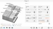
Modern hotels set new standards for individual comfort. The smart hotel offers guests even more luxury and relieves the hotel personnel.
As sensitive data are also transmitted in such a hotel, those responsible should protect the data. Operation using a fully encrypted KNXnet/IP network and KNX Secure ensures customer data are protected. Scan the QR code on the right: at jung.de you will find concrete application examples.
WITH POWERFUL HOTEL SOFTWARE
VISU PRO SERVER 20320 S IPSR
JUNG.DE
VISUALISATION/OPERATION 275 274 VISUALISATION/OPERATION
Thirdpartysystems
Numerous sources of assistance
JUNG offers extensive additional information online: From instructions to webinars, everything to do with the Visu Pro software is available at jung.de.

JUNG WEB SITE
On the JUNG web site you can find all the information on JUNG Visu Pro, including brochures, pictures and press articles to download. Clearly presented and illustrated. Naturally also with further links. JUNG.DE


QUICK START GUIDES
Integrating voice control with Alexa and Google Assistant, setting up remote access or creating a presence simulation: the JUNG quick start guides provide extensive help about the JUNG Visu Pro and are available online as PDF to download.

WEBINARS

In the interactive webinars, JUNG provides everything worth knowing, including about Visu Pro. Participation is free and there is the possibility during the webinar to ask the JUNG training team questions.
Visu Pro is optimised for all smart controls and mobile devices. The contemporary operation of all important building functions is completely simple and intuitive as a result. JUNG KNX Secure and HTTPS encrypt the data exchange.


JUNG ONLINE CATALOGUE

The individual items have technical information attached in the JUNG online catalogue that can be viewed and downloaded. You can find operating instructions, tender texts, datasheets, product documentation and more with a mouse click using the Info button.


KNX bus line Data Secure IP Secure IP (LAN, https encrypted) IP (WLAN, https encrypted) KNX Secure 2 6 3 7 2 PROTECTED WITH INTELLIGENT JUNG TOPOLOGY 1 KNX system device 2 KNX RF media coupler 3 KNX power supply insert 4 KNX RF node 5 KNX TP actuator 6 KNX TP sensor 7 JUNG Visu Pro Server Hotel Edition 8 LAN router Smart Control displays Smart Control 19 Smart Control 15 Smart Control 10 Smart Control 7 Smart Control 5 Mobile devices Mobile automation with tablet /smartphone
Secure
The interplay of JUNG Visu Pro and clients (e.g. the JUNG Smart Control touch display) is optimised to the smallest detail. Intuitive operation, comprehensive compatibility and regular extension of the functional scope place the user and the user’s needs at the core. JUNG VISUALISATION/OPERATION 277 276 VISUALISATION/OPERATION
exchange of the data
KNX Visu Pro Server
Ref.-no.
Visu Pro Server fanless, without rotating parts including plug-in power supply
German with Europlug
JVP-SERVER-H2 English including adapter for UK and China
JVP-SERVER-H2GB
Intended use
• Visualisation and operation of KNX systems via devices with HTML5 browser or app (iOS, Android), e.g. Smart Control (ref.-no.: SC 5 SW, SC 7.1 .., SC 10.1, SC 15.1, SC 19.1), smartphone, tablet, laptop, PC, etc.
• Support of KNX IP Secure and KNX Data Secure (as of version 4.5)
• Operation in local IP networks that support DHCP (Dynamic Host Configuration Protocol), or with static IP address (IPv4)
• Desktop device, mounting on DIN rail according to EN 60715 possible
• Max. size of the visualisation project as template in JUNG Smart Assistant
• Connection to KNX bus via interfaces (ref.-no. IPR 200 REG, IPS 200 REG, IPR 300 SREG, IPS 300 SREG, 20320 1S IPS R, 2131 USBS REG, 2131 USBS), not included
Product characteristics
• Fanless mini PC
• JUNG Visu Pro software pre-installed and activated
• Windows 10 pre-installed
• Quadcore Intel Celeron processor
• 4 GB RAM
• 64 GB internal memory, partly used by operating system
• 1 x HDMI
• 4 x USB 3.0
• 2 x LAN RJ45 (LAN 1: static IP address, LAN 2: DHCP)
• The visualisation can be realised with devices with a browser suitable for HTML5 (e.g. latest version of Chrome, Firefox or Safari)
• Access from max. 10 different clients possible
• Integration of Amazon Alexa voice control via MyJUNG account
• Integration of Google Home voice control via MyJUNG account
• Secure remote access via MyJUNG account
• Update and upgrade compatible
278
Process connections
• KNX editor/ KNX editor 2.0
• instalight editor
• Device editor
• vitaLED editor
• XPL editor
• SENEC energy storage
• Process model
• Visualization editor
• Work sheet generator
• Calendar
• JUNG Visu Pro Starter
Data import from ETS
• ETS5: use of project export of ETS
• ETS4: use of project export of ETS
• ETS3: use of OPC export of ETS
• ETS2 version 1.1, 1.2 and 1.3: files generated by "print export" can be read
• Previous ETS versions: not possible
279 KNX Visu Pro Server
KNX Software
JUNG Visu Pro Software and JUNG Visu Pro Software Hotel
Note: The software can only be downloaded from the JUNG website https://www.jung.de/en/1508/service/ get-your-software-licence/. When downloading, you can choose between the English and the German version. Each installation will run in demo mode for 20 days or 400 starts. For an unrestricted use the software must be activated via a MyJUNG account.
Intended use
• Visualisation and operation of KNX systems via devices with HTML5 browser or app (iOS, Android), e.g. Smart Control (ref.-no.: SC 5 SW, SC 7.1 .., SC 10.1, SC 15.1, SC 19.1), smartphone, tablet, laptop, PC, etc.
• Support of KNX IP Secure and KNX Data Secure (as of version 4.5)
• Connection to KNX bus via interfaces (ref.-no.IPR 200 REG, IPS 200 REG, IPR 300 SREG, IPS 300 SREG, 20320 1S IPS R, 2131 USBS REG, 2131 USBS), not included
Product characteristics
• Access from max. 20 different clients possible (with Windows 10)
• Integration of Amazon Alexa voice control via MyJUNG account
• Integration of Google Home voice control via MyJUNG account
• Secure remote access via MyJUNG account
• Update and upgrade compatible
Process connections
• KNX editor/ KNX editor 2.0
• instalight editor
• Device editor
• vitaLED editor
• XPL editor
• SENEC energy storage
• Process model
• Visualization editor
• Work sheet generator
• Calendar
• JUNG Visu Pro Starter
Requirements
Hardware as for Visu Pro Server (ref.-no.: JVP-SERVER-H2) or better
Please note: The performance of the hardware is one of the limiting factors for the project size.
Operating systems
Windows 10
KNX editor
The Falcon driver of the KNX Association is used for the KNX bus. The KNX connection requires a suitable version of the Falcon driver and the respective interfaces.
Data import from ETS
ETS5: use of project export of ETS
ETS4: use of project export of ETS
ETS3: use of OPC export of ETS
ETS2 version 1.1, 1.2 and 1.3: files generated by "print export" can be read
Previous ETS versions: not possible
280
JUNG Visu Pro Software
Full version JVP-V
Planner version JVP-P
JUNG Visu Pro Software Hotel
Full version JVP-HOTEL
Special function HOTEL
Extension of the KNX editor to max. 150 KNX tunnel connections
Communication via KNX IP Secure Tunnelling
Integration of third-party systems:
• Door locking systems of Assa Abloy
– Guest card identification
– Staff card identification
– Access counter / documentation
– Evaluation of the door locking system
• Hotel booking software Protel PMS
– Guest identification per room

– Receive requests from the hotel room (e.g. Do not disturb, Make up room etc.)
– Change the room temperature of the PMS system
• Oracle Hospitality OPERA or Oracle Hospitality Suite 8 PMS

– Guest ientification per room


– Receive requests from the hotel room (e.g. Do not disturb, Make up room etc.)


– Change the room temperature of the PMS system

JUNG Visu Pro remote access licence


Remote access to the building technology via JUNG server in Germany.
Smart Assistant
Smart Assistant is a planning tool for the simple creation of visualisation projects for the JUNG Visu Pro software or other automation applications. The use of conventions and schemes (trade, floor, room, function) does not require knowledge of KNX group addresses. Export formats are available for JUNG Visu Pro software and ETS group addresses.
Requirements
Server/client-based software, but can be used with one PC Operating systems for server: Windows 10
Clients: Browser suitable for HTML5 (e.g. latest version of Chrome, Firefox or Safari)
281 KNX Software
Ref.-no.
unlimited N JVP-L
JUNG VISU PRO HOTEL
KNX Accessories
Ref.-no.
KNX product data base
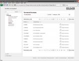
Database for ETS
www.jung.de/en > Downloads > Technical Downloads Bus connection block red/black (for KNX)
2050 RT SW yellow/white
Connection cover for bus terminal of rail mounting devices
2050 GE WS
2050 K
Button lever for the simple and gentle deinstallation of rockers and covers W-KEIL


282
KNX catalogue
DATED 01/01/2021
The current terms of sale and delivery can always be found on our web site at: jung.de/terms
JUNG ON-LINE CATALOGUE
This and many other items are available in the JUNG online catalogue. Operating instructions, tender texts, datasheets, product documentation, prices and much more can be found with just one click: jung.de/katalog
Our terms of sale, delivery and payment apply exclusively. The images shown are not binding, particularly with respect to colour, size and equipment of the products presented. The prices given here do not apply once a new price list has appeared.
JUNG only supplies specialist electrical businesses via electrical wholesalers.
IP News Protection type IP 44 possible
High-quality laser engraving with the Graphic Tool is possible Colour printing with the Graphic Tool is possible
LEGEND
N L P
ALBRECHT JUNG GMBH & CO. KG
P.O. Box 1320
58569 Schalksmühle
Germany
Phone + 49 2355 806-553
Fax + 49 2355 806-254 international@jung.de
For sales cantacts in your country see: jung-group.com/contact
JUNG-GROUP.COM
B-GB-KNX 0321
