2018-2021 SelectedWorks Portfolio. U N. Ibrahim Architecture
Statement of Authorship
I, Ubaid Ibrahim, hereby certify that the work produced in this portfolio is entirely of my own creation. The original work from the professional experience has been adapted for this portfolio, and I do not posess ownership of them.
Ubaid N. Ibrahim
MSc. Architect Designer
Highly Motivated curious and design-driven. Extremely adaptable to new challenges and environments. Result-driven on a collaborative and individual level. Ability to multi-task and work on different stages of designing.
PROFESSIONAL EXPERIENCE
Intern Construction Technology* Mar ‘22GlobalArchitects|DenHaag,Netherlands
Summary : Measuring Historic Buildings ; preparing the draft of existing buildings and addition of new layers via ArchiCAD ; Creating presentation for Clients Drafting Projects using Sketchup Adobe Creative Suite. *current position
Intern Architect
KoenVanVelsenArchitects|Hilversum,Netherlands
Summary : Elective Traineeship during MSc at TU/e Collaboration with team on two architectural projects. Drafted orthogonal drawings using AutoCAD and Revit. .Creation of3D
Junior Architect
BuseDastanArchitects|Istanbul,Turkey
Summary Varying tasks, including presentation drawings for clients;working on website renders advertisement design.
3D Artist
AgifodentxSantasariaNazari|Erasmus+Traineeship|Granada,Spain
Summary Designing of 3 dimensional motifs, that were later prepared for photogrammatery with CNC machines. Working with CNC machines was part of the process. Painting
SOFTWARE SKILLS
Feb’ 20 - April ‘20
EDUCATION
Feb’ 19 - Aug’ 21
Masters of Science in Architecture (MSc)
FacultyofBuiltEnvironment|EindhovenUniversityofTechnology Full-time|Netherlands
Sep’13 - Jun’ 17
Bachelors of Architecture & Design (B.Arch)
FacultyofArchitecture&Design|BahçeşehirUniversity(BAU) Full-time|Turkey
PROJECTS
Tensile Structure Workshop
BahçeşehirUniversity(BAU)|Winter2016|Istanbul,Turkey
Feb’ 18 - Jun ’ 18
Sep’ 16- Feb ‘17
Exchange Semester (Erasmus +)
FacultyofCivilEngineering&Architecture|UniversityofMaribor 6months|Slovenia
Sep’ 17- Dec ‘17
ACHIEVEMENTS
University Scholarship (50%)
BahçeşehirUniversity(BAU)| Istanbul,Turkey
Summary Entrance Scholarship given out to students with outstanding academic record
Honor Roll
BahçeşehirUniversity(BAU)| Fall‘14,Fall’16&Spring’16|Istanbul,Turkey
Summary Certification of Appreciation for High Academic standing.
Study grant Erasmus +
Erasmus+|Sep’16-Feb‘17|Maribor Slovenia
Summary Grant administered by Turkish Educational Sector to limited students who display a high CGPA and fair well in an English proficiency test(OCLC).
ACTIVITIES
Member; AnArchi
EindhovenUniversityofTechnology|Feb’19-Sept’21|Netherlands
Summary Active member of The Architecture faculty’s study association participating in magazine editing(text), competitions,
Volunteer : Van Abbehuis
Eindhoven Netherlands
Summary : Organizing and partaking in a workshop consis��ting ofa series of lectures, after which practical excercises were carried out in teams of students. Fabric and tensile steel was used to create these structures.
Neighbourhood Workshop-Technical School in Barcelona(Etsab)
BahçeşehirUniversity(BAU)| Winter 2016 Istanbul, Turkey
Summary A field-trip followed by a design competition. Successfully organized a series of visits to different ethnic neighbourhoods in Istanbul. Presentation of cases were followed by a design excercise to show the gradual changes in those areas. The workshop consisted of participants from ETSAB and BAU.
SKILLS
Adaptability Problem-solving Self-management Efficiency Interdepedence
Summary :Van Abbehuis is a comtemporary art Museum; activities involved scanning visitors ticket, guiding them to the exhibition rooms and on-going activities at the venue.
LANGUAGES
English Advanced C2 (Native-like)
HOBBIES
Turkish : Intermediate (B2)
Urdu : Advanced (Native) Dutch Beginner (A1)
Photo-walking travelling architecturalphotography Readingabouthistoryandpolitics, Hiking,hitch-hiking,workaway-ing
2021 2022 2020 2019 2018 2017 2016
PROFILE
Rotterdam, Netherlands ubaidibrahim1994@gmail.com | +31621405810
https://www.linkedin.com/in/ubaid-ibrahim/
Adobe Illustrator Adobe Indesign Adobe Photoshop Rhinoceros Grasshopper V-Ray Autodesk 3dsMAX Sketchup Enscape Autodesk AutoCAD Autodesk Revit ArchiCAD
CV 1


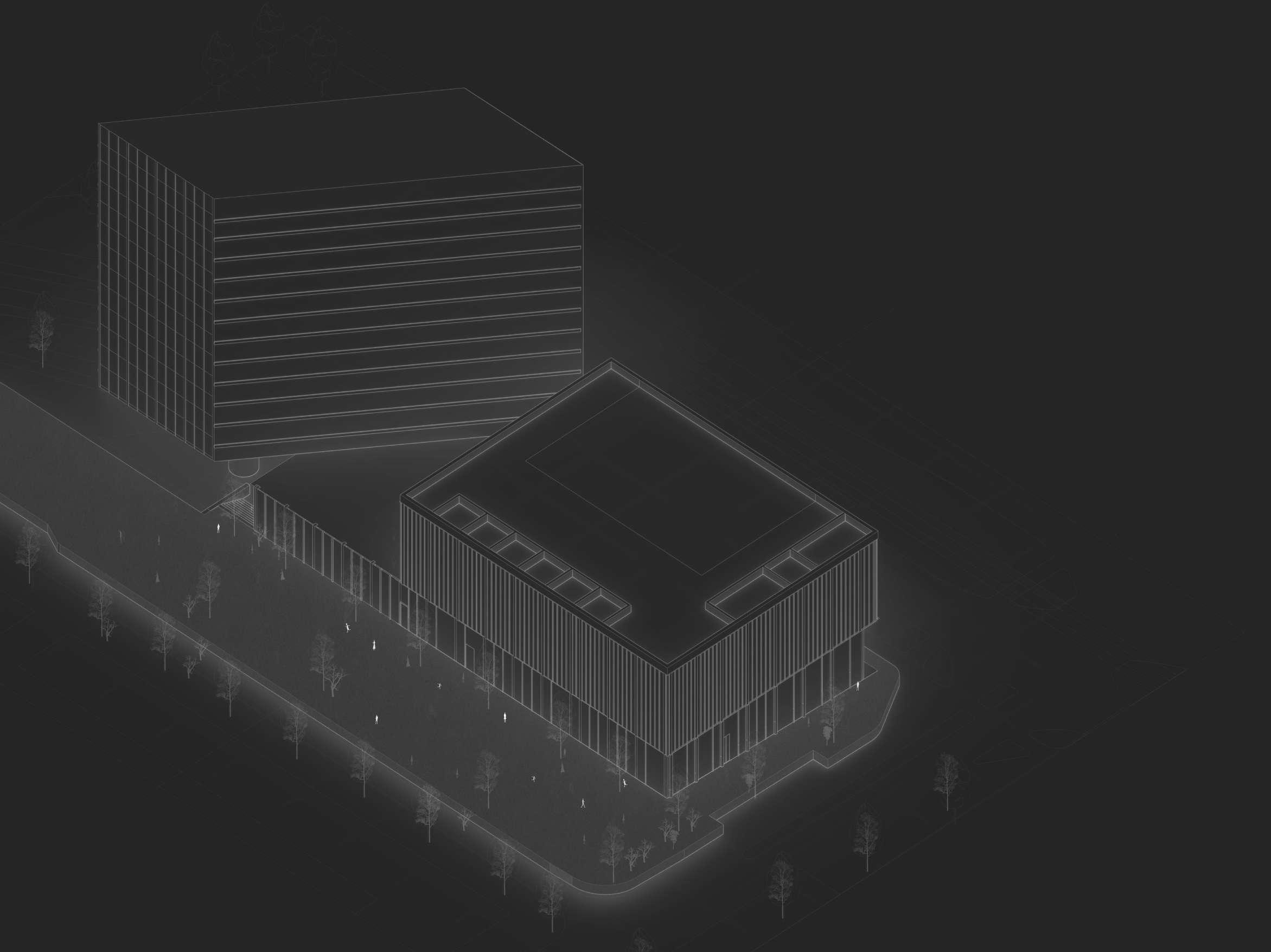
2018 2017 2021 2020 2019 Academic Autonomous Spaces Da Vinci’s Bridge Redesigning in Detail Masters Studio : Architecture of Power ParametricDesignofASustainable,HealthyBridge ArchitecturalEngineeringandModelMaking Nov’19 - Jan’ 20 Feb’ 20-Jun’ 20 Feb’ 20-Apr’20 01 02 03 Huis Op Zuid Koen Van Velsen Architects Hilversum, Netherlands Professional Work Bus Station Leiden Koen Van Velsen Architects Hilversum, Netherlands Feb’ 20- Apr’20 Feb’ 20- Apr’20 Ulus Residential Complex Feb’ 18 - Jun 18 Buse Dastan Architects Istanbul,Turkey 01 02 03 CONTENTS CONTENTS 6|PART 1 PART 1|A Table of Content Academic Work Table of Content |Professional Work
Autonomous Spaces
When it comes to the confluence of Architecture and power, capital cities occupy a place of special significance. In a capital city especially in cases where they have been explicitly designed to be capitals, the architecture and urban design sponsored by the state carries an undeniable political agenda, albeit one subject to multiple interpretations. Bucharest is one such city. Capital cities are not only the result of political decisions; they are meant to embody and envelop them. One of the main concerns of this master studio is to uncover the relationship between power and architecture, or in more general terms, between politics and urban space, as this relationship is manifested in the (re)making of a capital city. Along these lines the key question of the studio was: “What is the relationship between particular styles and designs, and the power structure of the regime responsible for building the capital?”
To distill these notions, a design- based research is carried out for the Palace of Parliament in Bucharest. The building was designed and constructed in the period 1984 – 1997 by the architect Anca Petrescu commissioned by Nicolae Ceaușescu the general secretary of the Romanian Communist Party. This exploration resulted in eleven design proposals questioning the ideological and historical representation of this building and its potential transformation from different perspectives.

Site Location : Bucharest, Romania
 Palace of Patriarche
Master Studio : Architecture & Power Advisors : Husnu Yegeneoglu Oana Druta
Contributors : Raluca Munteanu, Alexandru Tanase, Dorothee Hasnas
Fig 1.1 - SiteAxnometric ofThe Palace ofParliament &TheAutonomous Spaces
YEAR 2020 | LOCATION BUCHAREST, ROMANIA | TYPE : ACADEMIC
Design for reusing Palace of Parliament, Bucharest.
Palace of Patriarche
Master Studio : Architecture & Power Advisors : Husnu Yegeneoglu Oana Druta
Contributors : Raluca Munteanu, Alexandru Tanase, Dorothee Hasnas
Fig 1.1 - SiteAxnometric ofThe Palace ofParliament &TheAutonomous Spaces
YEAR 2020 | LOCATION BUCHAREST, ROMANIA | TYPE : ACADEMIC
Design for reusing Palace of Parliament, Bucharest.
01
21
Academic Experience Autonomous Spaces | Architecture of Power
DESIGN STRATEGY
The strategy devised takes into account the original N-S Axis upon which the old Bucharest existed. The design strategy draws from the concept of ‘Deconstructivism’ and the different Architectural ‘syntax’ that can be used to rearticulate space. The strategy proposed attacks the Monumentality of Palace of Parliament with a Monumental Intervention one that seeks to ‘democratize’ the loose spaces, atop the Uranus Hill upon which the Palace is situated. Using the existing parking and vehicular mobility routes present under the Uranus Hill the Palace is well connected underneath. However on the surface it is very detached. With Deconstructivism comes the following strategies by which space is rearticulated;
Extrusion, Rotation, Offset, and the imposition of Grids. Using the shape of a Ziggurat, as a model, the base of the palace is rearticulated.


-15 level is accessible by vehicles and pedestrians alike. The spaces above that build up to the ground floor of the palace, are resultantly more pedestrian friendly.
 1. Left overspace around Uranus Hill 2. Existing Network ofPedestrian |Vehicularmobility
Fig 1.2 - Existing Site Conditions ( Left)
Fig 1.3 - Existing Conditions ofPalace ofParliament (Right)
1. Left overspace around Uranus Hill 2. Existing Network ofPedestrian |Vehicularmobility
Fig 1.2 - Existing Site Conditions ( Left)
Fig 1.3 - Existing Conditions ofPalace ofParliament (Right)
22 | Academic Experience Autonomous Spaces Design Strategy


 Fig 1.4 - Proposalto rearticulate leftover spaces
Fig 1.5 - Sequence ofArchitectural elements, that form part of the intervention
1. Left overspace around Uranus Hill
2. 50x50m grid to add levels |Articulate Space
3 . Expansion ofUnderground network (-15)
3. Public Pathways and green areawas configured next.These pathwayswere extended outwards to allowforvisibilityon both sides.
6.VerticalCirculation (Ramps)were added in the last step.
2.The second architecturalelements,were the public passageways, mostlyforthe mobilityofcars.
1. In terms ofarchitectonics, the structure precedes relevance andwere the first elements configured using the grids.
3. Parking and green areaswere configured next.The GreenAreaswere used as a mediating space between the two types ofpathways : forvehicles and users.
Fig 1.4 - Proposalto rearticulate leftover spaces
Fig 1.5 - Sequence ofArchitectural elements, that form part of the intervention
1. Left overspace around Uranus Hill
2. 50x50m grid to add levels |Articulate Space
3 . Expansion ofUnderground network (-15)
3. Public Pathways and green areawas configured next.These pathwayswere extended outwards to allowforvisibilityon both sides.
6.VerticalCirculation (Ramps)were added in the last step.
2.The second architecturalelements,were the public passageways, mostlyforthe mobilityofcars.
1. In terms ofarchitectonics, the structure precedes relevance andwere the first elements configured using the grids.
3. Parking and green areaswere configured next.The GreenAreaswere used as a mediating space between the two types ofpathways : forvehicles and users.
23 | Academic Experience Autonomous Spaces | Sequence
5.Verticaladdition oflevelswas the next step.The green spaceswere also separated.


 Fig 1..6 - Resultant Spaces
1. Pedestrian pathwayunderthe Uranus Hill.
Fig 1..6 - Resultant Spaces
1. Pedestrian pathwayunderthe Uranus Hill.
24 | Academic Experience
2. Green and recreationalspaces Autonomous Spaces |Scenes
Conclusion
The goal of this design-research was to reassert the importance of breaking power structures through Architecture. In the Post-Modern era Architecture must transform, in order to make spaces more accessible, for an ordinary person. By making a space more accessible for an ordinary person, the design strategy takes back ‘power’ and creates spaces that are autonomous ; free from the grasps of hierarchal separation.

25 | Academic Experience Autonomous Spaces
Redesigning in parametric
Redesigning in Parametric is a project about designing a pedestrian pathway that can replace the Pedestrian passages present at the Eindhoven University of Technology’s Campus. Several themes were the basis of the concept and design process of the ‘Da Vinci’s Bridge’. The themes selected were sustainability and health. These themes inspired the materiality, and the addition of a single landing staircase between the pedestrian bridge. The bridge draws inspiration from the history of TU e campus, as it becomes more pedestian and bicycle friendly, the redesigned bridge with a stairwell was a conscious decision to include an architectural element that enhances the possible adjustable parameters within the design. Several parameters that are adjustable were designed via grasshoppper which makes this redesign adjustable to fit between different gaps , between different buildings present at the campus.
Task : Concept
Parametric Script (1/2)
Research Text
Booklet Design
Rendering/ 3d modelling
Site Location : Eindhoven, Netherlands
 Collaborators Marino Moschella , Marko Masostuni
Fig 2.1 - SiteAxnometric ofDaVinci’s Bridge
Da Vinci’s Pedestrian Bridge
Collaborators Marino Moschella , Marko Masostuni
Fig 2.1 - SiteAxnometric ofDaVinci’s Bridge
Da Vinci’s Pedestrian Bridge
YEAR : 2020 | LOCATION EINDHOVEN, NETHERLANDS TYPE ACADEMIC GROUP 02 26| Academic Experience Da Vinci’s Bridge | Redesigning in Parametric


 1. SequenceA;TheTU buildings are disconnected. In this era, the ground floorwasvehicle friendly.The buildingswere accessiblevia the first floor
2.The newbridges are added, to make the access between buildings easier.
3.TU Eindhoven becomes a campus, onewhich is accessible bybikes and pedestrians..With assigned roads and restricted access, the use of space changes in the current stage.
1. SequenceA;TheTU buildings are disconnected. In this era, the ground floorwasvehicle friendly.The buildingswere accessiblevia the first floor
2.The newbridges are added, to make the access between buildings easier.
3.TU Eindhoven becomes a campus, onewhich is accessible bybikes and pedestrians..With assigned roads and restricted access, the use of space changes in the current stage.
27 | Academic Experience
Fig 2.2 - Site evolution
Da Vinci’s Bridge Concept Generation
Parameters
The
The script for the el are divided into three parts.
.1. Elements Design :
Unit a.
Longitudinal Beams

Stairwell
 Fig 2.3- DaVinci Bridge ( ModulesA+B) (Above)
A a a c b B
Fig 2.4 - ModulesA,B,CAs showin the node generation of the DaVinci Bridge (Right)
adjustable parameters include the Modules A B and C. The smallest unit of the arches needed to be rotated in order to fit the A-B-C connection between the arch pairs.
28 | Academic Experience Da Vinci’s Bridge Parameters
Elements’ Design


 Fig 2.5-The sequence and Grasshopperscript generation ofthe main elements ofthe design.
29 | Academic Experience Da Vinci’s Bridge | Parametric Script
2.Rotation |Arch Generation


3.Longitudinal
 Fig 2.6 - Rotation,Arch Generation Scripts
1. Ground Frame A+B
2. Module A+B
Beams
Fig 2.6 - Rotation,Arch Generation Scripts
1. Ground Frame A+B
2. Module A+B
Beams
30 Academic Experience Da Vinci’s Bridge | Parametric Script
3. Details


 Fig 2.7 - Details ofDaVinci Bridge
1.
2.
3.
Fig 2.7 - Details ofDaVinci Bridge
1.
2.
3.
31 | Academic Experience Da Vinci’s Bridge | Parametric Script


32 | Academic Experience Assembly Catalogue Da Vinci’s Bridge
YEAR
: 2019 | LOCATION Utrecht, NETHERLANDS | TYPE : ACADEMIC
Redesigning in Detail
Courtyard Space: Janskerkhof 2-3A, , Utrecht Faculty of Law
Architecture Firm : Max and Steketee Architects
Professor : Jan P.A. Schevers
The project focuses on redesigning of an existing detail with a desired outcome detail to be more sustainable than the original. The courtyard space for the study centre in Utrecht Faculty of Law, called Janskerkhof, 2-3 a was selected for this project. The existing detail, designed by Max and Steketee Architects, consists of a wooden column, a triple glazed glass roof with aluminum reinforcements and fixtures. To get a grip on which architectural elements of the courtyard space could be redesigned, a survey and drawing analysis was conducted for the entire building, as part of the process. As a result three major changes were made to the courtyard space, that were explicated with a redesigned detail.They are as follows :
1. Replacement of the Aluminum Frame to a Wooden One
2. Replacement of Triple Glass Roof with four layered Bio-degradable Inflatable Plastic Roof
3. Changing the Gutter in wood redesigning the basin to adjust to the other beams
Location Utrecht, Netherlands
Project Size : Tasks :
-3d Model : Site/ Context/ Sequence/Material/Detail (Old and New)

-Physical Detail (1:1) -
-Transporting/Carrying material/Participation in cutting/assembling/joining detail
-Interviewing Architect(Max Steketee)
Fig 3.1 - Image Courtesy:The Courtyardswith thewooden column and beams
03
33 | Academic Experience
in Detail
Collaborators Ewout Vrugt ,Hagar El Frargy, Arghavan Khaefi, Redesigning

 Wooden Columns
WoodenBeams
Steel Gutters
SecondaryElements (Fixing the roof)
Aluminium Frame
Glass Roof
Wooden Columns
WoodenBeams
Steel Gutters
SecondaryElements (Fixing the roof)
Aluminium Frame
Glass Roof
1
Backside Glass FinalFraming
Fig. 3.2 (left) Explodedviewofthe courtyard
34 | Academic Experience Redesigning in Detail | Existing Condition
Fig 3.3 (right) Ground FloorPlan ofUtrecht FacultyofLaw( Highlighted Courtyard Space)
Original detail
 Fig 3.4- 3dAxonometric ofOriginalCourtyard Detail
35| Academic Experience Redesigning in Detail | Existing Condition
 Timber column and beam
SteelLprofile andwaterproofmembrane Rockwool insulation
The basin/gutter
Fig 3.5 - Sequence ofConstruction
The aluminium finishing
Final detail
The primaryalminiumwindowframe
Timber column and beam
SteelLprofile andwaterproofmembrane Rockwool insulation
The basin/gutter
Fig 3.5 - Sequence ofConstruction
The aluminium finishing
Final detail
The primaryalminiumwindowframe
36 Academic Experience Redesigning in Detail | Existing Condition
The secondaryalminiumwindowframe
Redesigned detail
 Fig 3.6- 3dAxonometric ofNewCourtyard Detail
37 | Academic Experience Redesigning in Detail New Detail

Timber
Addition
finishing Final detail
The newbasin design The newgutterdesign
column and beam
backwall The aluminium
38 Academic Experience Redesigning in Detail New Detail
Fig 3.7 - Sequence ofConstruction (newdetail)

2m 0 bioplastic inflatable system hardboard aluminium finishing Rockwool 18 mm OSB 60 mm Timber water-resistant membrane 39 Academic Experience Redesigning in Detail New Detail
MODEL-MAKING PROCESS


40 Academic Experience Redesigning in Detail Model-Making Process

41 | Academic Experience Redesigning in Detail | 1:1 model of detail
Bus Station Leiden
The Bus Station Leiden project is one of the upcoming projects led by KVV Architects. A larger study and proposal is generated as a result on a conceptual level.
The Bus Station Leiden is a part of a larger macro scale project that consists of :

• Skyscrapers around the centre and expanding the business districts.
• Creating larger public avenues and spaces around the train station on the ground level.
• Alternatives for public landscapes.
The proposals were still in their initial stages during my traineeship. The status of this project is ongoing.
Fig 1.1 -ViewofBus Station (Exlusion ofSkyscrappers) Isometric View
Location : Leiden Centraal Area : 56.5 m 2 Tasks : -Area Calculation
Perspectives
Status : Conceptual Stages | YEAR : 2020 | LOCATION : HILVERSUM, NETHERLANDS | TYPE : TRAINEESHIP
Site
-Orthographic projections -
and Views
01
4| Professional Experience Bus Station Leiden
Koen Van Velsen Architects


 Fig 1.2 - Programmatic Scheme ofBus terminaland its pertaining Skyscapper(Left)
5 | Professional Experience Bus Staiton Leiden | Programme
Fig 1;3 - Programmatic scheme ofproposed skyscrappers (right)

5m 0
6
Fig 1.4 -Ground Floorplan Bus Stop Scale 1:250
Professional Experience Bus Staiton Leiden Floor Plan
YEAR : 2020 | LOCATION Rotterdam, netherlands| TYPE : internship
Huis Op Zuid
Located in South Rotterdam next to Paul Kruger Street is Huis Op Zuid ( House on South).
It is a multi-functional building, which is both a sports complex and residential building. The project scheme consists of three masses, the sports complex building, the base of the plinth, that connects the residence tower and the complex together. And finally, the residential tower. The mass of the residential block is tilted,angled to maximize sunlight. The facade consists of an alternating rhythm of concrete and metal strips. These strips and their rhythms match the sports complex on the front, and the residential building on the back. The building is also separated by entries at two different levels and risers on the external part to connect the two levels inside and out. My tasks for this project included making an exterior 3d model. I also edited and post-produced some floor plans and facade drawings of the buildings. The status of this project is completed.
Site Location : Rotterdam, Paul KrugerStraat.
Total Site : Total Project Area : Status : Completed(Under Construction)
Fig .2.1 - Building and Site, Isometric
Koen Van Velsen Architects
02 7 | Professional Experience Huis Op Zuid

Key 1. Entrance 2. Instructiebasin 3. Corridor 4. Toilets 5. Locker Rooms 6. Storage 7. ShowerArea 8. Ramp & Staircase area 9. Exit 10. wedstrijdbassin 11. Pool
Sports facility Scale 1:250 1 2 3 4 5 6 7 8 10 11 9 2.5m 0 8| Professional Experience Huis Op Zuid Floor Plan
Fig 2.2 -Ground Floorplan ofthe

9|Professional Experience Huis Op Zuid | Facades
Fig 2.3 - Front and Side Elevations; Scale 1:250
Ulus Residential project
The Ulus Residential Complex, a proposed project by BDA Architects in coalition with the municipality of Nespitye, Besiktas.
The Ulus Residential Complex is situated on a once green, inaccessible and undulating terrain. The Complex splits this topography into three clear levels each with its own skyscraper. This project is still in its design stage.
Site Location : Besiktas, Istanbul
Tasks : Site Precedents/Analysis
Orthographic Drawing(AutoCAD)
Municipal Documentation/Area Calculation
Post-production (Render/Orthographic drawings)
Total Project Area : 227,592 m 2
 Fig 3.1 - Isometric Section ofthe Built Complex ; Featuring Residential, LuxuryHotel, Public, Recreationaland Office Spaces.
YEAR 2018 LOCATION ISTANBUL,TURKEY | TYPE : WORK 03
Buse Dastan Architects
Ulus Residence | Professional Experience 10
KEY
Residential Space


Public Space
Services/Technical Space

Parking (Residents)


Circulation
 1.The site limits against its toopgraphicalbackground
3. Readjustment and division of the plinth into 3 sections, according to the topography, and public-private spaces.
5.Towers readjusted according tovisualaxis, and sun directions.
4. Addition of residential units on the basement levels, based on the sun route. extrusion ofthe masses ofthe skyscrappers, positioned according tovisuallinks along site
6. Towers, readjusted + rotated to articulate the views and let in more light.
2. Extrude : Expansion ofbase using a 800x800cm grid to articulate public functions on the plinth ofthe skyscrapper.
Fig .3.3 - Form generation Diagram (left)
1.The site limits against its toopgraphicalbackground
3. Readjustment and division of the plinth into 3 sections, according to the topography, and public-private spaces.
5.Towers readjusted according tovisualaxis, and sun directions.
4. Addition of residential units on the basement levels, based on the sun route. extrusion ofthe masses ofthe skyscrappers, positioned according tovisuallinks along site
6. Towers, readjusted + rotated to articulate the views and let in more light.
2. Extrude : Expansion ofbase using a 800x800cm grid to articulate public functions on the plinth ofthe skyscrapper.
Fig .3.3 - Form generation Diagram (left)
| 11
Fig 3.4 - Programmatic Diagram (Above) Huis Op Zuid Program and Development


20m 0
Fig .3.4- Ground FloorPlan ofthe foyers to theTowersA,B,C
Scale 1:500
Block B Block C 12 | Professional Experience Ulus Residence Floor Plan
Zoomed in plans Block B ,C Scale 1:250

13| Professional Experience Ulus Residence |Sections
Fig .3.5 - LongitudinalSection ofProject Scale 1:500

14| Professional Experience Ulus Residence Sections
Fig .3.6 -Transverse Section ofTower Scale 1:250

15 | Professional Experience Ulus Residence Post-Production
Fig .3.7 - Perspective exterior
ubaidibrahim1994@gmail.com unibrahim.myportfolio.com behance.net/unibhm
END
