6 minute read
PVC PRESSURE PIPE — DESIGN ELEMENTS
HYDRAULIC DESIGN
One step in hydraulic design is to determine friction head-loss by using either of these equations: 1. Darcy–Weisbach Equation The Darcy-Weisbach Equation is found in many hydraulic textbooks but is not included in this guide . The pipe-material parameter in this equation is called “absolute pipe roughness .” A pipe roughness value of 7 .0 × 10-6 feet should be used for PVC pipe . 2. Hazen–Williams Equation Research has shown that the Hazen-Williams flow coefficient (or “C Factor”) for PVC pipe is between 155 and 165 . 3 A conservative value of C = 150 should be used for design of PVC pipe systems .
Advertisement
Unlike many other materials whose coefficients reduce over time, PVC pipe’s Hazen-Williams and Darcy-Weisbach coefficients remain unchanged . For more information on both equations, see the “Hydraulics” chapter of the Handbook of PVC Pipe Design and Construction . 4 Design engineers use the following to optimize sizing of pipes and pumps: Pipe dimensions Pipe material friction factors Projected wastewater flows Pipe profile and stationing
After basic hydraulic parameters for the project have been established, pump and system curves are used to determine pressures and flows within the system for various operating conditions . The hydraulic profile is then established . This information enables the designer to specify the pressure class (PC) or pressure rating (PR) of PVC pipe to meet project requirements .
INTERNAL PRESSURE DESIGN CHECKS
To design PVC pipe for internal pressures, there are three design checks that a selected PC or PR must meet . These checks ensure that the pipe can accommodate maximum operating pressure, recurring surge pressure (cyclic surge, such as pump start-up/shut-off), and occasional surge pressure (worst-case surge, such as power failure) . The PCs of AWWA C900 and PRs of ASTM D2241 include a safety factor of 2 .0 .5,6 Note: in the following design checks, the AWWA notation “PC” is used . For ASTM pipe, “PR” is substituted for “PC .” An online calculator developed by PVCPA is available for these design checks (Internal Pressure Design Calculator) .
WPmax ≤ PC × FT
(First Design Check)
Prs(max) = WPnormal + Prs ≤ PC × FT (Second Design Check)
Pos(max) = WPmax + Pos ≤ 1.6 × PC × FT (Third Design Check)
Where:
WPmax = working pressure during maximum pump operations, psi
WPnormal = working pressure during normal pump operations, psi
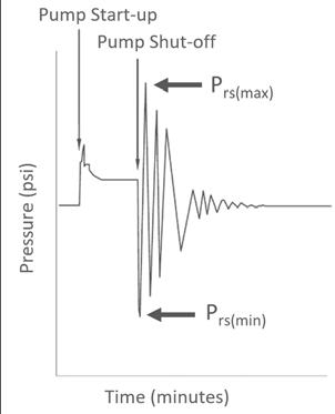
Prs = recurring surge pressure, psi (from typical pump on/off operation)
Prs(max) = maximum pipe pressure from a recurring surge event, psi
Pos = occasional surge pressure, psi (worst-case transient scenario, e .g ., power failure)
Pos(max) = maximum pipe pressure from an occasional surge event, psi
PC = pressure class, psi (Appendix Table B .1)
FT = thermal derating factor, dimensionless . If sustained operating temperatures are above 73°F, a thermal derating factor should be applied . (Appendix Table B .2)
The WP subscripts in the design checks are for multiple-pump operations . For lift stations that operate only on a single pump, the design checks are modified as follows:
WPmax = WPnormal because only one pump is operating .
CYCLIC PRESSURE DESIGN CHECK
Cyclic pressures (also called “recurring surge pressures”) are typically not frequent enough or large enough in water transmission or distribution mains to be a design consideration . In contrast, surge pressures occur at high frequencies in force mains due to pumps operating to empty small-capacity wet wells . This means that a fourth design check is required for force-main applications . Utah State University has performed cyclic-pressure research and analysis to develop an improved method for determining cyclic life for PVC pipe . The research involved testing numerous samples of PVC pipe to failure and then analyzing the number of cycles and the pipe wall stresses . The result is the “Folkman Equation .
”7 If the number of surge cycles the pipe will experience is known, the result of this equation can be used to determine the life of the pipe (“cyclic life”) from these recurring surge pressures . The calculated cyclic life should exceed the specified design life, as shown in the design check below .
Cyclic Life ≥ Design Life
(Cyclic Design Check)
Cyclic life refers to the number of years PVC pipe can withstand cyclic pressures and is not an overall life expectancy . Rather, it is the amount of years PVC pipe will endure recurring surge pressures alone .
DETERMINING PVC PIPE CYCLIC LIFE: 1 . Stress amplitude is found using maximum and minimum pressures from a surge event (Equation 1) 2 . Number of cycles to failure is calculated (Equation 2) 3 . Cyclic life is obtained by dividing number of cycles to failure by number of surge occurrences (or cycles) per year (Equation 3)
EQUATION 1
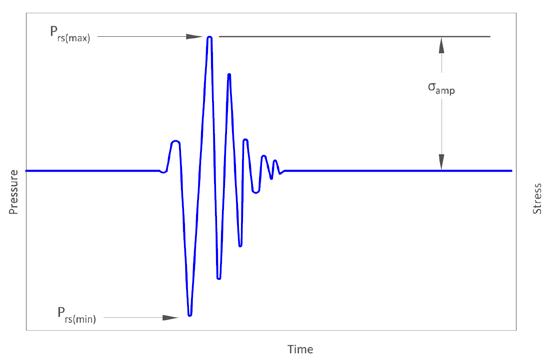
σamp = [Prs(max) – Prs(min)](DR– 1) 4
Where: σamp = amplitude of pipe wall hoop stress from cyclic pressures, psi
Prs(max) = maximum pipe pressure from a recurring surge event, psi
Prs(min) = minimum pipe pressure from a recurring surge event, psi
DR = pipe’s dimension ratio, dimensionless = OD/t
EQUATION 2 (FOLKMAN EQUATION)
N = 10–4.196log(σamp)+17.76
Where:
N = number of cycles to failure
EQUATION 3
Cyclic Life (years)= N n
Where: n = number of cycles per year from pump operations
FIGURE 2: TYPICAL SURGE PRESSURE AND STRESS BEHAVIOR IN A SEWER FORCE MAIN
In summary, the cyclic life of PVC pipe depends on: 1 . Number of surge occurrences 2 . Magnitude of these recurring surges 3 . Pipe wall thickness (DR) Methods for determining surge pressures for PVC pipe are discussed in the next section . See Design Example for how these design checks are used .
DETERMINING SURGE PRESSURES
JOUKOWSKY EQUATION: Surge pressures in PVC pipe are typically determined using the Joukowsky Equation, which is based on the pressure wave speed through the pipe and instantaneous change in flow velocity . Table 1, derived from the Joukowsky Equation, provides surge pressures caused by a change in velocity of 1 foot per second (ft/s) for each representative DR . The following is an example of how the table is used: if design velocity in a DR 21 pipe is 5 ft/s, anticipated surge pressure is 16 .0 psi/(ft/s) × 5 ft/s = 80 psi .
8 Alternatively, transient analysis software can be used to determine surge pressures . This method provides more accurate results, especially for complex pipe systems and operations . Scenarios for normal pump on/off operations and for worst-case surge events (such as a power failure) can be used for the PVC pipe design checks mentioned in Internal Pressure Design Checks . Figure 3 is an example of a graph produced using transient analysis software to model a PVC force main .
TABLE 1: PRESSURE SURGE FROM A 1 FT/S INSTANTANEOUS CHANGE IN FLOW VELOCITY
Values from the Joukowsky Equation
DR PC/PR (psi) Surge Pressure (psi)
51 80 10 .8
41 100 11 .4
32 .5 125 12 .8
26 160 14 .4
25 165
21 200 14 .7
16 .0
18 235 17 .4
14 305 19 .8
Note: For values where DR is not shown, the pipe manufacturer should be consulted .
FIGURE 3: TRANSIENT MODEL OF NORMAL PUMP ON/OFF OPERATION

When appurtenances (i .e ., air valves or surge-control devices) are used in a piping system, transient software is generally preferable, regardless of pipe material . Pump station and pipeline design manuals provide specific conditions when transient modeling is recommended . If such software is not available, use of the pressure surge values from Table 1 is typically valid and conservative . The design example in the next section shows how to use both methods for determining surge pressures .


