
2 minute read
SHERLOCK I

The testing was done with Pete Rhodes, K4EWG, in Georgia, ... who used a home-brew vacuum tube receiver.
keying waveform which, when input to the AWG, causes its output to be a keyed 7 MHz RF signal to the antenna.
Advertisement
The antenna system was a coax switch to select the AWG in transmit or the Yaesu receiver. A 50- to 75-ohm L-network matches the 50-ohm transmitters to the LMR-400 75-ohm lowloss coax, two-wavelengths long. The antenna is a 40-meter dipole of eightgauge stranded wire at about 30 feet, facing east/west.
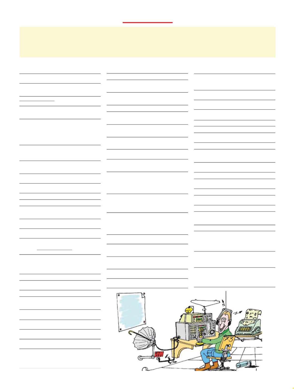
The testing was done with Pete Rhodes, K4EWG, in Georgia, about 150 miles straight line distance from my QTH in Tennessee, who used a homebrew vacuum tube receiver. The test was to first establish communication with the Yaesu, then switch to the AWG at a maximum of 10 volts P-P output, which is 406 milliwatts into 50 ohms, and then reduce power even further. I transmitted the P-P voltage levels and Pete replied with S-meter readings.
At 10 volts P-P, the received signal was S-9 with fading. The power was then reduced in 1-volt increments to one volt, 4.06 milliwatts, at an S-3 reading. Still too strong!
Then the voltage was reduced from 1 volt to 100 millivolts in 100-millivolt increments. A voltage of 0.500-volts PP, 1.01 milliwatt1 , at S-0 was readable; 400 millivolts and below was copyable but not readable in the noise. There’s little point in testing below that level; a milliwatt is on the order of the power from an oscillator and far below what most wattmeters can read.
Very carefully designed and matched antennas are required for such testing. My 40-meter dipole, with very low loss coax and designed based on transmission line principles, has a 1:1 SWR across the band with a 3:1 SWR bandwidth of about 1.5 MHz. The receive antenna must also be very efficient to receive small signal levels. My antenna is at 800 feet above sea level, but also “down in a hole” and emitting through tree leaves, which causes some attenuation.
A video of the QSO is on YouTube at <https://tinyurl.com/4rwskx9t>.
Note: 1. P-P voltage level of 0.5-VPP verified on a Tektronix 50-ohm scope. With an estimated 0.5-dB transmission line loss (Times doesn’t give an exact spec on loss), that might leave 950 microwatts at the antenna feedpoint. HamTestOnline
www.hamtestonline.com ANTENNAS: Delta Loop HF, HGSW Beam, Multiband Antennas, Cage Dipole, Emergency Communications Stealth Antennas, Single Band Half-Wave HF Dipoles BALUNS & A ANTENNA ACCESSORIES: Antenna Accessories, Rope, Ends, EZ Hang; Baluns & Line Isolators: Tower Accessories ACCESSORIES: Radios, Capacitors, Solar 3861 Mount O Olive Church Road Moravian F Falls, NC 28654 (828) 738-6445 website: www.ni4l.com


