18 minute read
Lille Langebro in Copenhagen


A New Harbour Crossing Lille Langebro in Copenhagen
by Simon Fryer
Advertisement
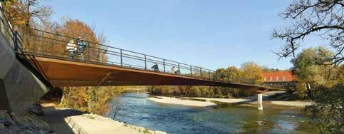
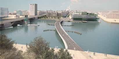
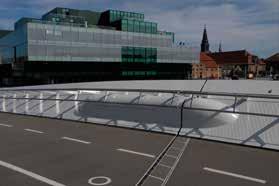
1 Completed bridge in Copenhagen © Buro Happold
The Lille Langebro is a major new pedestrian and cycle bridge over the harbour in Copenhagen. The bridge forms a sleek, low level crossing that curves in plan as well as elevation. The superstructure consists of fabricated steel box sections of complex geometry and includes two balanced double cantilever spans on slew bearings which rotate to allow the passage of large ships. The rotating spans are fixed together in the closed position by an arrangement of proprietary mechanical components which form an innovative structural moment connection at mid-span. With a cost of DKK 90 M the bridge delivers excellent value for money in comparison to other similar crossings around the world. It enhances Copenhagen’s worldwide reputation as one of the best cities for cyclists and has quickly established itself as a popular new landmark.
1 Introduction
The Langebro bascule bridge which was constructed in 1954 is one of only two vehicular bridges crossing the harbour in the centre of Copenhagen. It carries traffic between the busy Hans Christian Andersen Boulevard and Amagerside Amager Boulevard and is not convenient for non-motorised users as it has narrow footways and no dedicated cycleways. In 2014, client Realdania announced an international design competition for a combined pedestrian and cycle bridge to be placed immediately north of the Langebro adjacent to their Blox mixeduse development. A team of designers comprising Buro Happold (engineers), Wilkinson Eyre (architects) and Eadon Consulting (specialist mechanical engineers) submitted the winning entry, which was selected in 2015. This new bridge was later to be christened the »Lille Langebro« in deference to its neighbour following a public vote.
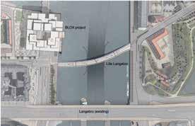
2 Bridge location plan © Wilkinson Eyre
3 Concept design of the bridge © Wilkinson Eyre
The bridge has two sections that rotate to allow shipping through a central navigation channel. The mechanical parts are hidden within the concrete piers and steel superstructure. To maintain a slender profile in elevation, an innovative moment connection has been designed to connect the moving parts together. This clever connection simultaneously clamps the sections and allows longitudinal movements arising from temperature. It also acts as a viscous damper to reduce vibrations and improve the user experience. After an initial phase of scheme design and approvals, tenders for the new bridge’s construction were invited in 2016. The selected contractor was a joint venture between Mobilis Danmark and Hollandia. The design team was novated to the joint venture and completed the detailed design of the bridge under their guidance. Work on site commenced in 2017 and the bridge was successfully completed in the summer of 2019. This article focusses on a number of the innovative and interesting features of the design and construction of the bridge.
2 Design competition
The design brief was for a new cyclepedestrian bridge and the landing points on either side of the harbour were predetermined by the existing road layout. When closed, the requirement was for a navigation envelope of 20 m wide by 5.40 m high. A clear passage width of 35 m was required when the bridge was open to allow for shipping to pass. The clear width of the bridge was specified as 7 m to allow for a 4 m bi-directional cycleway segregated from a 3 m footway and the overall construction budget for the bridge was DKK 90 M (12 M €). The geometric requirements informed the choice of bridge alignment. To provide the required clearance over the water, elegant vertical and horizontal curvature was introduced leading to an overall bridge length of 166 m. The centre
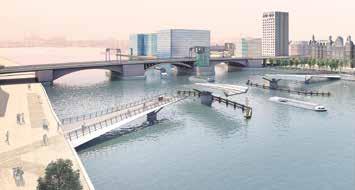
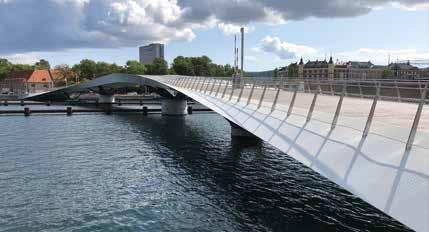
4 Bridge in open position © Wilkinson Eyre
of the bridge was elevated relative to its ends and therefore views of the city and harbour were provided. To avoid obstructing these views, the structural depth was minimised. It consists of main triangular edge members which alter their inclination from one end of the bridge to the other. The inspiration for this was the wings of a swan as they flap up and down in flight, but it also provides an efficient structure. The bridge was designed with four sections, two of which were fixed approaches with the central two pieces able to rotate to allow shipping to pass. The opening sequence provides a visual spectacle and surprising element of the design. Provision was made for the navigation passage to be marked by a vessel collision protection system.
3 Steel superstructure and pier arms
The bridge design incorporates several innovative features and presented a number of challenges. Attention was paid to every detail of the bridge to ensure its finished quality. The main longitudinal edge members were formed from triangular box sections, typically of 15 mm thickness. The plates forming these boxes incorporate double curvature due to the complex geometry and so the structural design of the boxes and their internal stiffness was heavily influenced by the practicalities of fabrication. A key visual feature of the bridge is the outer corner of these boxes and great care was taken with detailing this area. The pier arms supporting the superstructure are also formed from steel box sections of varying profiles adding further complexity to the fabrication details. An orthotropic deck spans between the outer members. The longitudinal stiffeners follow the sweeping path of the bridge, adding interesting views of the soffit. Architectural considerations meant that it was important to conceal the bridge mechanism as far as possible. Hydraulic power units are housed in cavities inside the longitudinal beams. Enlarged chambers are provided adjacent to the moment connection for the hydraulic rams and associated mechanical parts. The bridge parapets are a bespoke design consisting of rails housing light fittings to provide illumination to the deck as well as architectural feature lighting of the outer edges of the bridge. They are infilled with stainless steel mesh and have an undulating profile to accentuate that of the steelwork. Concealed lighting in the handrails illuminates both deck and wings; at night the bridge appears as a twisting ribbon of light between abutments.

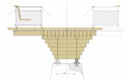
5 6 Typical cross sections of Lille Langebro © Buro Happold
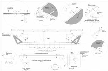
7 Deck steelwork details © Buro Happold
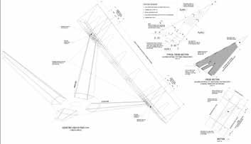
8 Pier arm details © Buro Happold
4 Concrete substructure and foundations
The four bridge piers in the harbour were formed within cofferdams and consist of concrete structures founded on limestone, with the two hollow central piers to house the motors and slewing ring bearings of the rotating spans above. Concrete piled abutments were constructed behind the quay walls on either side of the channel. The harbour piers are robust enough to resist high ice loads in the event of the harbour freezing over or there being large accumulations of floating ice. A secondary vessel collision protection system has been provided on either side of the navigation channel to provide additional security for the bridge and its supports from ships, and this system extends around the bridge sections when they are in their open position.
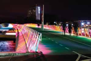
9 Lille Langebro during the Copenhagen light festival © Buro Happold
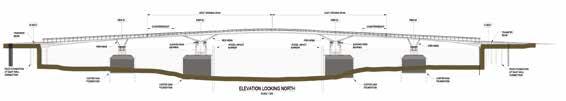
10 Long section of the bridge © Buro Happold
The bridge is operated from a console within the control tower of the adjacent Langebro road bridge. Power is also supplied from this bridge, with a network of underwater cable ducts on the seabed providing the connection to the piers of the fixed and moveable spans.
5 Computational aspects and shading study
The complex geometry of the steel structure with constantly varying cross section and plates in double curvature necessitated a sophisticated workflow to generate the analysis model. The bridge geometry was defined by the architect in Rhinoceros and analysis models were created at each of the design stages in Midas Civil. A line model was employed during scheme design because it provided a quick and agile solution to represent the geometry that was likely to be subject to change as the design was optimised. A more sophisticated model was required to fully understand the global stress distribution across the bridge, specifically under a nonlinear analysis. A shell model was created by interrogating the architect’s model to approximate Tolerances in the connections and joints could then be accurately determined via a dialogue with the contractor. The shading patterns were determined by modelling the position of the sun in Rhinoceros to view which plates were exposed to direct sunlight at different times of the day and seasons of the year. Thermal loads could then be applied to the corresponding plate elements to match the shading patterns. This enabled a direct application of a temperature variation through the cross-section which was combined with the uniform global expansion and contraction of the bridge. The approach is considered conservative, but it provided confidence in the design tolerance for the different joints along the bridge. The project proved a useful lesson in developing a computational approach to designing complex structures. The investment of time on the project to developing these skillsets paid dividends by greatly improving the efficiency of otherwise time-consuming analysis work.
the geometry of the curved plates. The creation of shell elements was automated using scripting in Grasshopper. This model was used to create nonlinear, dynamic and localised models. This method provided an efficient way to generate an accurate representation of the longitudinal girders, whilst the secondary elements were represented as line beam elements. The correct alignment of the joints is critical for the bridge to function. The principal element giving rise to differential movements between bridge sections is the effect of temperature which causes the bridge to expand and contract. Variance in temperature between the different faces of the steel members can also cause displacement and rotation. The codified methods of modelling differential temperature effects were not easily applicable to the bridge’s complex form. Therefore, an extensive study from first principles was carried out to predict the maximum differential displacements that would occur by applying a range of thermal loading scenarios to match the expected shading patterns on the bridge in both the open and closed positions.
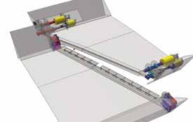
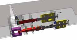
11 Central moment connection © Eadon Consulting Ltd. 12 Diagram of central moment connection © Eadon Consulting Ltd.
6 Bridge mechanism and central moment connection
To maintain a slender profile in elevation, a unique arrangement of mechanical components was devised to connect the moving parts together at mid-span. This innovative solution clamps the sections together forming a moment connection under pedestrian loading but is released to allow longitudinal movements arising from temperature. The clamping action means the bridge is much stiffer and less prone to deflections and vibrations than if it were connected using a traditional locking pin in the middle. The moment connection is achieved via a pair of hydraulic cylinders located within each of the two bridge box girders. The upper mechanisms generate compressive resistance whilst the lower mechanisms generate a tensile force. When engaged in its socket, the compression mechanism also provides shear continuity and vertical alignment of the two moving spans. The tension and compression elements within each beam are hydraulically connected in such a way that, as the vertical load increases on the bridge due to pedestrians, hydraulic pressure increases in the system generating the moment resistance. However, when the bridge expands and contracts due to changes in temperature, oil will flow from one cylinder to the opposing one, relieving pressure and generating no resistance. This release of axial forces significantly reduces the horizontal loads and resulting moments acting on the bridge piers and foundations. This in turn allows economic sizing of the slew bearings, where the avoidance of tension is desirable, and consequently the concrete piers which house them. The reduction in moments at the piers also reduces the size and cost of the cofferdam foundations constructed in the channel. Under dynamic pedestrian excitation the moment connection acts as a viscous damper as the restricted flow rate of the hydraulic oil between the cylinder is slower than the frequency of the loading cycle. Therefore, the connection is effectively axially restrained under dynamic loads. This significantly improves the dynamic performance of the bridge, keeping predicted vertical accelerations within comfort levels and avoids the need for any additional damping.
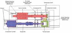
13 Enlarged view of hydraulic cylinders © Eadon Consulting Ltd.
The final size of the hydraulic cylinders of the central moment connection was larger than anticipated during preliminary design stages. As the components are located within the hollow box beams, a blister detail was developed to provide the increase housing required. This impact on the architecture at a critical location on the bridge is minimised by the horizonal orientation of the parapets at the mid-span region which helps to mask the appearance of the blisters.
14 Central moment connection © Buro Happold
The mechanical moment connection is an improvement over more traditional horizontal locking pin arrangements that can suffer problems with excessive wear. The forces involved would require a large pin which would have to extend into a deep socket, presenting a high risk of jamming due to repeated friction of the pin against the socket. The choice of mechanical components used has minimal moving parts and no surfaces grind against each other, reducing wear and the risk of jamming. Care has been taken in the design of the moment connection to ensure that the mechanical parts are as simple as possible and can be readily accessed for maintenance. The system has been designed using a combination of proprietary products to ensure reliability of the individual components and that they can be easily replaced if needed. The provision of the moment connection was critical to achieving the low height structure desired by improving the strength and dynamic performance of the bridge. Achieving a reliable moment connection in the centre of a moving bridge is a key innovation in the field of movable bridge structures. It uses tried and tested equipment in a new way to deliver many significant benefits over a traditional locking pin arrangement.
7 Bridge fabrication
The four bridge sections were entirely prefabricated in the workshop of Hollandia Infra at Krimpen in the Netherlands. The fabricated geometry was adjusted from the theoretical final geometry using pre-sets provided by the design team at every point on the bridge to account for permanent deformations. Individual plates were first accurately bent to the correct curvature by C.I.G. Architecture, specialists in 3-D-formed steel fabrication, who were able to achieve the very close tolerances required. A jig was built within the workshop for the assembly of each bridge section. As most of the welding was below the bridge, it was convenient to assemble the bridge sections upside down and then turn them using a crane. Special lifting points were designed for this purpose and the permanent structure was verified for this temporary condition. The total mass of the steelwork was 456 t giving a steel density of the bridge of 263 kg/m2, which is highly economical considering this total also includes the substructure elements.
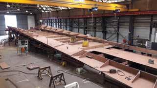
15 Bridge being fabricated upside down in workshop © Hollandia Infra b.v.
From the competition stage it was the intention for the bridge superstructure to be prefabricated entirely off-site and delivered in a more or less completed state by sea. This approach improved quality, as work was carried out in factory rather than site conditions, improved safety and reduced the risk of delays due to unsuitable weather conditions. Mockups produced by the contractors at tender stage proved helpful for testing potential construction methods.
8 Installation and commissioning
The bridge superstructure was prefabricated entirely off-site and delivered in a completed state by sea. This approach meant improved quality as work was mostly carried out in factory rather than site conditions, improved safety, and less risk of delays due to unsuitable weather conditions. A full trial erection of the bridge was undertaken at the workshop before the bridge was delivered to site. Tests were also performed to ensure that the balance of the rotating sections was correct. Holding down assemblies were surveyed to check they matched up with the steel bridge sections to which they would be fitted. Full factory bench tests were performed on the bridge hydraulic and electrical systems as well as the software.
16 Flipping over of bridge section © Hollandia Infra b.v.
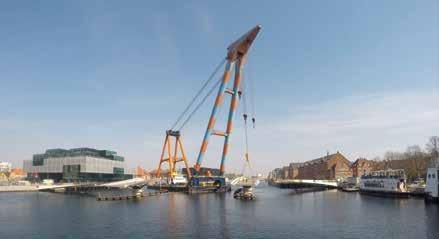
17 Bridge being installed using shear leg crane © Buro Happold
Once the bridge was ready, all four pieces were loaded onto a single barge at Krimpen and then towed via the Nieuwe Waterweg to Hoek van Holland and then onward over the sea through the Kiel Canal to the final destination in the centre of Copenhagen. A large capacity shear leg crane (Hebo Lift 9) met the barge on site and proceeded to install the bridge sections onto the pre-prepared bridge supports. Final alignment could then be achieved by jacking. The entire transportation and erection operation took only 10 days with the closure to marine traffic at the site restricted to two days. Effort put into careful planning and allowance for construction tolerances paid off as no significant problems were encountered once the steel had arrived. Once the bridge installation had been successfully completed, extensive testing of the bridge’s operation was undertaken before it was brought into service. At the same time, finishing touches such as the road markings and landscaping at the ends of the bridge were finalised.
9 Sustainability
Sustainable development meets the needs of the present without compromising the ability of future generations to meet their own needs. The Lille Langebro was progressed with this aim in mind. The varying depth of structure responds to the structural demands at any given point along the bridge, thereby adding interest whilst making the best use of materials. Realising this efficiency within the demanding budget was made possible by the computational approach adopted by the design team. The bridge mechanisms have been designed for minimal wear and ease of maintenance and the inclusion of the innovative central moment connection has delivered substantial material efficiencies over a traditional pin connection. The counter-balanced swing mechanism requires relatively low power to allow the bridge to turn. The bridge is quiet in operation and therefore does not affect its environment adversely. Robustness in the pier design provides security against accidental actions such as ice loading and vessel collision and the use of high specification materials and components throughout the bridge reduces whole life maintenance burden. The use of off-site manufacture minimised the environmental impact of construction and provides a deconstruction method that is largely a straightforward reversal of the installation process.
10 Conclusion
The complexity of the project presented many challenges to the structural design and construction that were successfully overcome through close cooperation between the client, designers and contractors. Several lessons can be drawn from the project. In particular: – Given the important engineering benefits that the mechanical moment connection has brought to the project, the design team believes that there is significant potential to reuse the concept in the future. The concept could lead to greater incidences of moment connections being utilised in moving bridges, improving the efficiency and economy of such structures. – The computational approach adopted by the design team allowed changes to the analysis models to be implemented quickly. This enabled more design iterations for greater material optimisation and the detailed shading study to understand critical thermal movements. This approach was essential to delivering the design and analysis of this complex structure within the demanding budget. – The project has demonstrated the benefits of extensive prefabrication to control quality and achieve the very close tolerances required as well as to reduce on-site construction activities.
The production of mock-ups by the contractors during the tender stage proved useful to identifying preferred methods of construction and led to several design changes to improve the finished quality.
Overall length 166 m Steel tonnage 456 t
Plan area including structure 1734 m2 Steel weight density 263 kg/m2
Usable width
Cycleway width 7 m Equivalent carbon content 650 kg CO2e/m2
4 m Construction budget 90,000,000 DKK
Footway width 3 m Cost per m2 (2015) 51900 DKK/m2
Navigation channel width 35 m Cost per m2 (2015) 6975 €/m2
18 Technical Specifications © Buro Happold
The bridge was officially opened to the public on 14th August 2019. With a cost of DKK 90 M the bridge delivers excellent value for money in comparison to other similar crossings around the world. The bridge enhances Copenhagen’s worldwide reputation as one of the best cities for cyclists and has quickly established itself as a popular new landmark.
Author: Simon Fryer Technical Director Buro Happold, London, Great Britain Client Realdania, Copenhagen, Danmark
Architects Wilkinson Eyre, London, Great Britain
Lead Engineers Buro Happold, London, Copenhagen, Berlin
Mechanical Engineers Eadon Consulting Ltd., Rotherham, Great Britain Local Engineers Niras A/S, Allerod, Danmark
Construction Mobilis Danmark A/S, Copenhagen, Danmark Hollandia Infra b.v., LG Krimpen aan den IJssel, Netherlands
Specialists M&E SH Group, Svendborg, Danmark
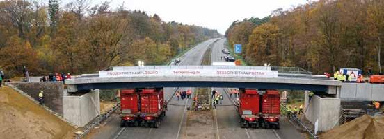
Steht in 2880 Minuten: die patentierte HEITKAMP Schnellbaubrücke ®.
Falls Sie dieses Wochenende noch nichts vorhaben: Bauen Sie doch mal Brücken mit HEITKAMP. Die sind an nur zwei Tagen aufgestellt, ermöglichen Stützweiten bis < 40 m, werden nahezu ohne Eingri e in den Verkehr gebaut und bestehen darüber hinaus aus voll recyclebaren Bausto en. Durch ihre leichte Rückbaubarkeit würden sie sich eigentlich auch optimal als temporäre Bauwerke anbieten. Aber diese Vorstellung wäre doch zu traurig. Wenn Sie mehr über unser Patent Nr. 302020104989.3 wissen wollen, rufen Sie einfach vor dem Wochenende hier an: +49 2325 57-15 51