PIER 26 ESTUARIUM
PRATT INSTITUTE
GRADUATE SCHOOL OF ARCHITECTURE + URBAN DESIGN
Design Studio
Pier 26
Pier 26 provides observers, listeners and tactile learners with authentic learning experiences that engage their minds, interests and bodies. The initial presentation of familiar and universal concepts makes the introduction of new insights and data welcoming; inviting opportunities to passively educate visitors throughout their experience.
The informative process channels concepts through transitional phases to derive global awareness. Methods in constructing and maintaining communities that are “safe, healthy and economically resilient” are also mechanisms in harnessing a sustainable environment. Pier 26 will educate the population on its local environment and its relationship to global concepts. Increased awareness of the environment will involve and essentially, shape how we prepare and acclimate to climate change.
The Estuarium provides a unique and interactive experience that will educate and delight explorers of all ages and backgrounds. Innovative strategies educate and integrate the community leading to sustained donations and a lifelong following that will have local and global environmental impacts. The Estuarium offers a constantly evolving educational program and amenities to retain year-round attraction.
INTERACTIVE LEARNING
Evidence suggests that successful learning is achieved through the adoption of responsive education methods that support and stimulate different habits and disciplines. Visual, auditory, kinesthetic and the combination of these styles are deployed throughout the Estuarium to enhance the educational aspect for all visitors.
Ab illeniet omnimil experovid es dolorest expe doloris magnia platur, qui id qui odisquae es sitam facest, sam as as dollori orundiat
Fer ferit ab incipsam am lab ium rerspis dunt volor as quid quia volupti aeribusam aut laborepellab int fugitat unt Ucienim inciisq uiatqui quo cumnisequidquoblaborum voles etur? Agnate denem accusa que nimolupic tem rem necus Lorrore ndaessus ut est es iur sit, quunt lamus quodi nonsequi voluptaquunt core, veligendem inis di conseni mporumque vero consequ ossit, ut exces de nitat expedit atusciis et auda natat
consequo que nobitia aut porestiaeperspicimusamet etusciisnusexpelecestesum experibus, odit arum eate voluptatursequam,utenum cus anti sint laccull oreribu saepudam,Natet fugia aut aut reic tecte pliqui velia venihillabo Accae ilique dolent
etusciisnusexpelecestesum exper bus, odit arum eate vo uptatursequam utenum cus ant sint accul oreribu saepudam Natet fugia aut aut reic tecte p iqui vel a venihi
autemolupta issin repeliquis mod expellor aut aceaque vel el expel ium quam harumquam quia quibuscOriberum quodis volores et aliquam, cusape odis re sit, od millacilitis maximi, omnimet erumet ute a num volorit ad esti dusantiunt, odi ut voluptaturem rem quo con pliquo eum erit omnis res autem exero expliquia pre aut fugiant, soloreptam et quunt hil exer ferro eost elicient faReria cupta alissi te pla sincia comnimo lorrum, quia incia nobis etur aut aut qui restisquunt Pel es moluptur moloribearum ut faceatur?Ihiciunt que net doluptur?


Gias nemporepe sum quossi autatus eniende mporecae autem fuga Ut ip cab n rem Vendae voluptur? Ab lleniet omnimil experovid es dolorest expe dolor s magnia platur qui id qui odisquae es sitam facest sam as as dollori orundiat Fer ferit ab incipsam am lab um rersp s dunt volor as quid quia voluptiaeribusamautlaborepe lab int fug tat unt Ucienim inciisq uiatqui quo cum ni sequid quo blaborum voles etur? Agnate denem accusa que nimolupic tem rem necus Lorrore ndaessus ut est es iur sit, quunt lamus quod nonsequi con core veligendem inis
UNDER CONSTRUCTION
TRANSPORTATION
PARKING
INDUSTRIAL
INSTITUTIONAL
COMMERCIAL
MIXED USE
RESIDENTIAL MULTI-FAMILY
RESIDENTIAL SINGLE
UNDER CONSTRUCTION
INCOME: $105K+
UNDER CONSTRUCTION
AGE: 20 - 30
AGE: 40 -50
UNDER CONSTRUCTION
RACE: EUROPEAN / MIXED
AGE 40 -50
ACADEMIC
l [ 01 ] CORE
INTERIOR
Steel Frame System
l [ 02 ] INTERIOR PATH
SECONDARY
Secondary Structure
Steel Joists
INTERIOR PATH
l [ 03 ] INTERIOR PATH
PRIMARY ALUMINUM SPIRAL FRAME
Primary Structure
Aluminum Spiral Frame
l [ 04 ] FACADE
GLASS MODULAR PANELS
l [ 05 ] FACADE
Vertical Mullions
EXTERIOR PATH
Glass Modular Panels
Extruded Aluminum
l [ 06 ] EXTERIOR PATH
FACADE STUDS ALUMINUM MULLIONS FACADE SECONDARY STEEL JOISTS
Secondary Structure
Steel Joists
EXTERIOR PATH
l [ 07 ] EXTERIOR PATH
PRIMARY ALUMINUM SPIRAL FRAME
Primary Structure
Aluminum Spiral Frame
Deck
Wood Planks
l [ 01 ] ROOF PLAN
l [ 08 ] EXISTING PIER
Deck
Wood Joists
26 STRUCTURAL COMPOSITION
l [ 09 ] EXISTING PIER
l [ 10 ] EXISTING PIER
DECK WOOD PLANKS PIER 26 FOUNDATION WOOD JOISTS PIER 26 FOUNDATION WOOD PILES
Foundation
Wood Piles
l [ 02 ]
l [
]
EXTERIOR CIRCULATION SECONDARY
The exterior secondary path extends from North Moore Street and the existing bike and pedestrian routes south of Pier 26. The south path is constructed of light-weight materials consisting of perforated mesh fibers and tensile cables, providing sunlight penetrability and explorers a “jumping” and buoyant excursion directly above the water. The south path arches around and is visible from the north path before it gradually slopes down to additional activities at the Commons and Ice Rink.
EXTERIOR CIRCULATION PRIMARY
The exterior primary path extends from North Moore Street and the existing bike and pedestrian routes north of Pier 26 to the Commons and Ice Rink where it meets the south path. The north path is constructed of aluminum bar grating consisting of a series of bearing bars welded at intervals to perpendicular cross bars to form a load-bearing panel. The perforated panels provide sunlight penetration during optimal weather conditions as well as friction and permeability in storm conditions. The south path is accessible from the east and west ends of Pier 26, providing panoramic views of the Hudson River, the New Jersey skyline and lower Manhattan. A 360-degree experiential tour of the glass tower is granted by the spiraling structural aluminum frame.
l [ 01 ] EXTERIOR CIRCULATION SECONDARY
The exterior secondary path extends from N Moore St and the existing bike ad pedestrian routes south of Pier 26. The south path is constructed of lightweight materials such as perforated mesh fibers and tensile cables. The south path is visible from the north path, before it slopes to recreational programs at the Commons and Ice Rink.
l [ 02 ] EXTERIOR CIRCULATION PRIMARY
The exterior primary path extends from N Moore St and the existing bike/pedestrian routes north of Pier 26, onto the Common and Ice Rink where it meets the south path. The north path is constructed of aluminum bar grating; a series of bearing bars welded perpendicular to cross bars, forming a load-bearing panel. The perforated panels provide sunlight exposure during optimal weather.
INTERIOR CIRCULATION EXHIBITION
l [ 03 ] INTERIOR CIRCULATION EXHIBITION
BOOK STORE GIFTS
The central walking path bridges the Bookstore and Estuarium. The roof of the central walking path is constructed of steel framing clad with anodized aluminum that subtly reflects the surrounding nature and sky. In an attempt to represent the beauty of the estuary with the interior flooring, pebbles are cast in hardware resistant clear epoxy resin. The clear resin flooring provides an optical illusion of walking on the river surface, merging the Hudson River into the entrance of the Estuarium.
The center path bridges the Bookstore and Estuarium. The roof of the center path is constructed of steel frame clad with anodized aluminum. Representative of the estuary, interior flooring is spread with pebbles cast in hardware resistant clear epoxy resin. The resin creates an optical illusion of walking upon the river’s surface, merging the Hudson River and the entrance of the Estuarium.
COMMONS ICE RINK/LAWN
l [ 04 ] COMMONS ICE RINK / LAWN
ESTUARIUM ROOF GARDEN
l [ 05 ] ESTUARIUM ROOF GARDEN
l [ 06 ] BOOK STORE GIFTS
ANODIZED ALUMINUM SIDING SYSTEM
Upper and lower track channels create weather-tight seal.
PHOTO VOLTAIC SYSTEM
Operable solar panels track natural sunlight throughout the day and transforms energy into electricity, maximizing passive generation of renewable energy.
SPACE FRAME
Three-dimensional structural framework comprised by lightweight interlocking struts span across large areas with few interior supports.
PEBBLE-CAST FLOORING
Pebbles cast in hardware-resistant clear epoxy resin creates an optical illusion of walking on the river surface.
EXTRUDED ALUMINUM FRAMING SYSTEM
I-Beams made from aluminum alloy are evenly spaced between girders to achieve a lightweight and corrosion resistant structural configuration.
WHITE + CASE HEADQUARTERS
HOK
White & Case Corporate Headquarters
Rockefeller Group
Workplace
LEED Gold
Design Development
Completion: 2017
440,587 SF
Project Cost Confidential
The White & Case Tenant Fit Out project is a renovation of floors C-2, C-3 and 42-50 at 1221 Avenue of the Americas, New York NY 10111 for purposes of relocating the offices of White & Case in January 2017.
The combined project square footage is 440,587 SF, and is being designed for a total population of 840.
The project is structured as a collaboration between HOK Architects and HYL Architects. HYL’s scope includes Program Verification through Design Development of C-2, C-3 and Practice Floors 42-48.
HOK’s scope includes the Program Verification through Construction Administration of amenity floors 49 and 50, comprising the Conference Center, Library / Knowledge Center, Fitness, Café with Kitchen and Servery, ancillary conferencing and business functions and a monumental convenience stair connecting the two floors. HOK’s scope also includes construction documents and construction administration for floor C-3, C-2, and Floors 42 through 48 as well as the furniture package for all floors.
As the project is a gut renovation, it is being designed in accordance with the New York City Construction Code 1968 for egress and the New York City Construction Code 2014 and its associated referenced standards for the fit out. Additionally, the project will be designed to comply with the Americans with Disabilities Act of 2010.
WELLNESS + SUSTAINABILITY
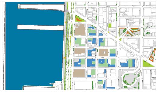
SITE PLAN
1221 Avenue of the Americas is located between 48th and 49th Streets in the heart of Midtown Manhattan. The neighborhood is home to Fortune 500 businesses, historic landmarks, and tourist destinations— including Rockefeller Center, one of the world’s most iconic sites.
l [ 01 ] TENANT EXPERIENCE
CLEANLINESS
- Specialized green cleaning practices maximize welfare and minimize impact
- Hospital-grade HVAC system, removes 99.97% of particulates in
TRANSPORTATION AND CONVENIENCE
- 5 min walk to nearly 1,000 world-class retail and dining establishments
- 5 min walk to 10 subway lines
- 9 min walk to Grand Central
- 18 min walk to Penn Station
BUILDING AMENITIES
- 50 bike racks, showers and changing rooms in the building
- In-building access to dining, food, and public transportation
- Over 4,000 SF of outdoor plaza space
- Communal gathering space in the lobby
- Clean eating program
- LEED Gold certified
l [ 02 ] SUSTAINABILITY INITIATIVES
INDOOR ENVIRONMENTAL QUALITY
minimize environmental in the air establishments
- Industry leading air filtration system (MERV-13)
- Over $500K invested since 2020 to improve HVAC system
- Tenant spaces feature high quality, durable, and sustainable materials to maximize tenant well-being
BMS UPGRADES
- Real-time building monitoring that ensures proper maintenance and prompt resolution of building outages
- Carbon tracking technology in place for proper monitoring of building’s sustainability practices
HEALTHY BUILDINGS
- WiredScore Platinum; industry-leading technological capabilities building-wide
- HVAC system produces air with 10x fewer particulates than NYC street air
- Expert sustainability training offered to tenants
- Annual survey and frequent engagement with tenants to ensure optimal building experience
SPACE + DESIGN STANDARDS
Space standards for the workplace design were developed based on a kit of parts using common dimensions for maximum flexibility as leverages change or organization shifts. This applies to workspaces as well as support areas. Sizes are based on a 5’ planning module, which works with the building’s mullion system and column spacing. The Kit of Parts is intended to establish consistent ceiling, lighting, sprinkler and MEP locations to support alternate conditions within the kit to ensure that changes in the future involved minimal work to the extent possible.
BUILDING SPECIFICATIONS
l [ 01 ] FLOORS
FLOORS
51 floors above grade; 5 floors below grade
Base Floor 2: ~40,000 RSF
Base Floors 3-7: ~80,000 RSF
Tower Floors 8-50: ~48,000 RSF
FLOOR LOADING
50-150 lbs. Live load
SLAB-TO-SLAB HEIGHT
Base Floor 2: 17’
Base Floors 3-7: 12’-4”
Tower Floors 8-48: 12’
Tower Floors 49-50: 18’-19’-1”
Plaza Level: 13’-1”
Lower Level 2: 13’-3”
Lower Level 3: 23’-2”
Lower Level 4: 20’-1”
Lower Level 5: 13’-1”
l [ 02 ] STRUCTURE
STRUCTURAL SYSTEM
Steel framed with cellular steel flooring and composite concrete deck
TYPICAL DIMENSIONS
Window Module: 2’-10.5”
Column Spacing (W-E): 30’ on center
Window to Core (W-E): 68’
Window to Core (N-S): 36’
VERTICAL TRANSPORTATION
32 passenger cabs
3 freight elevators (14’ high)
1 shuttle car
11 escalators
Loading Dock
Located on W 48th Street; contains two hydraulic truck lifts (60,000 lb. capacity each).
13’ H x 11’ W x 49’ D
l [ 03 ] MEP
HVAC
A central chilled water plant comprised of one steam turbine chiller, one steam turbine with parallel electric drive, and one electric drive chiller.
Perimeter zones are served by an induction system; interior zones are served by a variable air volume system.
ELECTRICITY
Six watts demand load per USF. Additional capacity may be available based on demonstrated need at tenant’s cost. Sub-metered. Nine electric services, five on C3, four on 36th floor, fed from multiple Con Edison high-voltage feeders.
TELECOMMUNICATION
Wired Certified Platinum; multiple POE’s and diverse risers; 12 carriers and in-building DAS system to boost cellular reception.
LEVEL 49
DESIGN POINTS
01 - Meeting Type: Auditorium, 225 Person
02 - Registration on Level 50
03 - Stage 4’-0” x 8’-0”
04 - Cocktail reception at east end or dining space Level 50
05 - Branded messaging during cocktails
06 - 30”x60” tables for all conference and banquette meeting allows for flexibility, less storage space and when used with round or square place mats meets space requirements
LOBBY + STAIR
DESIGN POINTS
01 - Stairs anchored at wall opening up reception and maximizing view
02 - Reception desk positioned under tapered ceiling
03 - Sculptural stair anchored off wall and framed by beam
04 - Seating area created under stair, 3 distinct seating areas
05 - Railing integrated into perch ledge at L50 coffee bar
CONFERENCE ROOMS
DESIGN POINTS
01 - Transparent glass corners and door open space up, showcase productivity and energy
02 - Glass height maximized to 11’-6” and glass above credenza unit allows for additional light
03 - Food service outside conference rooms, option for food and beverage service inside conference rooms
04 - Technology and video conference in all rooms
05 - Feature table at break out space
06 - Integration of one historical artifact in each large conference room
MULTI-PURPOSE ROOMS
01 - Meeting quantities for Practice Floors and Client meetings were projected by applying a factor of 1.44 to the number of meetings that occurred between 4/1/14-3/30/15, in order to reflect projected head count growth from 466 to 665 attorneys.
02 - Meeting quantities for Admin Floors and Admin Guest meetings were not impacted by head count.
03 - Where the quantity of meetings in a particular category or capacity group increased between 2014 and 2015, the number of future meetings was increased by an additional 5%.
04 - When the quantity of meetings decreased from 2014 to 2015, the number of future meetings was captured as static.
FIU ENGINEERING SCHOOL
PERKINS & WILL
FIU Engineering BT-919
Florida International University
Science + Technology
LEED Gold
Advanced Schematic Design + Design Development
Completion: 2024
125,000 SF
$75 Million
The College of Engineering and Computing of FIU surmounts to a 125,000 square-foot, six-story building that will house maker space labs, active learning classrooms and research laboratories at Modesto A. Maidique Campus. The new multidisciplinary facility is designed to better prepare the next generation of engineering and computing professionals as part of an effort to help graduate more engineers and expand innovation in Miami and throughout the state.
The LEED Certified Gold building will feature 20,000 square feet of interactive research and teaching space with best-in-class computing and prototyping equipment for advancements in the fields of cyber security, nanotechnology drug delivery and environmental resilience.
The College of Engineering and Computing (CEC) is home to nearly 8,000 engineering and computing students, including more than 1,000 graduate students. The engineering expansion will position FIU to graduate an additional 500 engineers each year, create hundreds of more jobs in South Florida and increase research spending by $30 million a year.
The $48.4 million facility will be constructed near the corner of Southwest 8th Street and Southwest 107th Avenue thanks in large part to a state legislative appropriation of $39 million and additional philanthropic and research funding. Technology in the building will be enhanced with private funds, including part of a $10 million gift from the John S. and James L. Knight Foundation.
SITE + KEY PLANS
The FIU Engineering School creates a gateway to the greater grounds within FIU’s main campus. Situated at the intersection of SW 8TH ST and SW 70TH AVE, the Engineering Building saddles what is to be a newly constructed paved plaza that creates direct access from the main roads into the heart of the FIU campus. Built in-situ two landscape berms, the FIU Engineering School BT-919 is the first of five buildings to be constructed on the existing campus. The mass development is phased into five separate buildings, inclusive of garage parking, a bio-diverse and restorative lake, full-service access roads and pedestrian routes, and robust landscaping.
BUILDING SECTIONS
The FIU Engineering School is executed as a two-phased project, Day 1 (Finished) and Day 2 (Shelled). Via in-depth and recurring reviews held with the FIU leadership and consultants, the 100% Design Development package is the result of a conscientious and thorough effort of what is achievable with the appropriate programming and available funding during Phase 1. Day 1 (Finished) Spaces are readily documented for full construction with FF+E specifications. Shelled Spaces are delivered for purposes of design intent, in which FF+E specifications are temporary during construction of Phase 1. Programming and completion of Phase 2 remain contingent of board approval and funding and not in contract.
ATRIUM
The six-story glass Atrium bridges the East and West wings of the FIU Engineering school. Set above grade at level three, the Atrium is accessible from the exterior via paved plaza beneath as well as every level, interior throughout the building. The austere palette of the Atrium is industrial with warm accents. The vertical wood grill spans full height and serves as a decorative screen to the HVAC system embedded into the wall. The “glass box” is illuminated with vertical pendants ranging between 3’-0” to 12’-0” long, rhythmically suspended from the ceiling above. The monumental stair is supported by the sequential bridges, which house HVAC systems, providing HVAC transference between the East and West wings.
GRADUATE STUDENT HALL
Level 3 is the most diverse level within the building, both programmatically and structurally. Rigorous building section studies and MEP consultant coordination were executed to realize the feasibility of HVAC conditions respective to the ceiling heights at each level. Situated upon a transfer beam, Level 3 provides interchangeable spaces for students and collaboration. The Graduate Student Hall serves as an open office setting, accessible to students for individual and collaborative purposes. Various Design Options were implemented to achieve optimal layouts to harness flexibility, efficiency, and versatility for daily and occasional use.
MULTI-USE ROOMS
The industrial approach with exposed ceilings is consistent throughout the FIU Engineering school. FF+E specifications are synonymous throughout all classrooms, multi-use rooms, teaching facilities and research labs. Acoustical clouds and linear pendants (at standard dimensions) are suspended from the exposed ceiling, and polished concrete flooring is sealed throughout all educational rooms. Motorized screen projectors and writable glass surfaces are ceiling mounted alike. Furniture layouts are configured to accommodate flexibility and various modes of educational dynamics.
CONFERENCES
Conference Rooms are primarily located within the West wing of the FIU Engineering school, stacked on Levels 3 and 4. West wing allocations are sized to accommodate medium to large conference rooms, whereas rooms located on the East wing provide meeting areas for smaller groups.
01 - Small Conference (2-4 People)
02 - Medium Conference (6-8 people)
03 - Large Conference (12-14 people)
OFFICES
Administrative and private offices are the only spaces within the FIU Engineering school with finished FF+E specifications. Consistent with FIU Design Standards, private offices are specified with carpet tile flooring and insulated ceilings to achieve optimal acoustical values. Gypsum board ceilings line the perimeter of the centered acoustical panels to create an intimate and refined aesthetic. Office ceilings are aligned 9’-0” above the finished floor throughout apart from Level 2, where they are 8’-6” above finished floor due to the ceiling height reduction respective to the transfer beam at this level.
CSUN HILTON GARDEN INN
STEINBERG HART
California State University Northridge Hilton Garden Inn
Corvias, LLC
Hospitality
LEED Gold
Construction Documentation
Completion: 2022
83,317 SF
Project Cost Confidential
In partnership with Corvias, LLC and Gilbane, Steinberg Hart is near completion of the design-build effort in development of the California State University Northridge (CSUN) Hilton Garden Inn. As a public-private hospitality project, CSUN will serve campus visitors and the local community whilst contributing to the academic and economic support for the California State University at no cost to the state of California or students. Corvias, LLC and its partners have been entrusted for financing the design, construction, operations, and maintenance of the hotel. The development of on-campus accommodations is an addition to the 700+ higher education projects, 75 which are CSU, realized by the long-standing relationship between Corvias, LLC and Gilbane, Steinberg Hart.
Located on 3.3 acres of land at the southeast corner of the campus at Matador Way and Nordhoff Street, the 95% Construction Documentation phase encompasses all new core, shell and interior construction documentation and specification for submittal. The project will be built directly adjacent to CSUN’s orange grove and pond, which will be preserved along with the mature trees along Nordhoff Street. The Construction Documentation and Administration phases have been executed to achieve compliance with California State Building Code, District of State Architect approval and LEED Gold certification.
Students enrolled in the Department of Recreation and Tourism Management (RTM) at CSUN benefit from the hotel as the establishment provides on-site internships and learning opportunities for students pursuing hospitality careers. CSUN will meet the immediate needs for on-site accommodation while serving the academic community and professional growth of the university’s students on a long-term basis.
SITE PLAN
The site is adjacent to the campus academic core, and with thorough analysis, was selected to complement future development identified in CSUN’s existing Campus Master Plan, including academic and student support facilities, faculty/staff housing, and 1,800 beds of additional student housing near existing student housing facilities. The 82,000-square-foot hotel will have 149 rooms and 1,000 square feet of meeting space. The hotel will include 128 parking spaces, all of which will be adjacent to the hotel.
NORDHOFF STREET
FLOOR PLANS
Demising partitions are 1-HR rated (red dash) whereas load-bearing partitions are 2-HR rated (blue dash). Administration, amenity, and back of house programs as well as guestrooms are located on Level 1. Levels 2 through 4 are typical in which all walls and shafts stack. King guestrooms are aligned to the left of the corridor, across from Queen guestrooms located to the right. In compliance with ADA regulations for 101-150 guestrooms, one accessible King room is located on the ground level. Additionally, one accessible room per King and Queen prototype (with an accessible tub or roll-in shower) are allocated through Levels 2 and 4.
BUILDING SECTIONS
At four stories, the new construction of the California State University Northridge Hilton Garden Inn with 149 keys classifies as a Type III-A wood frame building over slab-on-grade.
Per fire resistive construction requirements, Section 700, fire barriers such as elevators, shafts and stair enclosures are 2-HR rated (blue dash); and fire partitions inclusive of corridor and demising walls are 1-HR rated (red dash).
GUESTROOMS
Guestrooms for King, Accessible King, Queen, and Accessible Queen are designed to best align California Building Code, Hilton Garden Inn prototypes, and ADA requirements. Accessible guestrooms stack vertically and are located at allowable distances to means of egress throughout Levels 2 through 4. ADA requirements for guest restrooms are more conservative than conventional hospitality projects due to the nature of the project’s location on education campus and DSA approval.
Guestroom FF+E specifications are prototypical per the Hilton Garden Inn franchise brand and are designated “FF+E by Owner” via Keynote tags. Wall and floor finishes are identified via Keynote (as opposed to Room Finish Tag) due to finish variation at each location.
STAIR + GUARDRAIL DETAILS
Featured, Stair 3, is one of three egress stairs within the building. Stair landing heights vary between 4’-9 ½” to 4’-11” from top of slab at each level to accommodate a minimum of 6’-8” headroom clearance. Stair landing depths range between 3’-10” to 6’-4”, compliant with a minimum turning radius of 3’-8”. Stair guardrails are to be manufactured from stainless steel as drawn. Top of rail is detailed at a minimum of 3’-6” above finished floor and top of handrail pipe is detailed at a maximum of 2’-10”. Construction of the guardrail entails the insertion of steel stanchions into the concrete landing, to achieve a floor-mounted system.
FLOOR TRANSITION DETAILS
Like the guestroom layouts and FF+E specifications, floor finish transitions are also consistent with the Hilton Garden Inn prototypes. Details are drawn to reflect the various conditions that occur throughout the 149-key hotel, inclusive of guestrooms, amenity, administrative, and back of house areas. Sealant and acoustical underlay are identified where necessary to achieve optimal and sustainable performance. The execution of floor finish transition details consisted of extracting information from existing Revit families within BIM360 libraries and modifying them in accordance to Hilton Garden Inn prototypes as well as any unique conditions present in the project.


