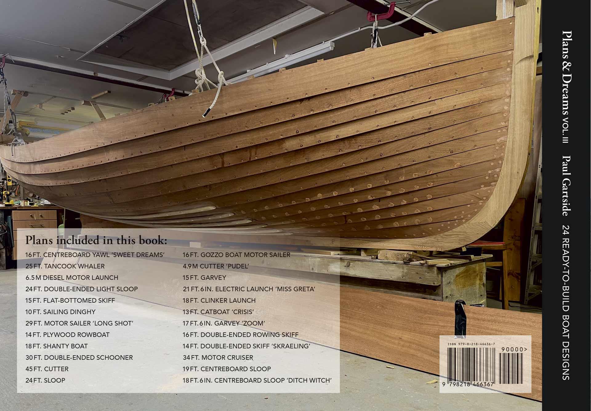
READY-TO-BUILD BOAT DESIGNS
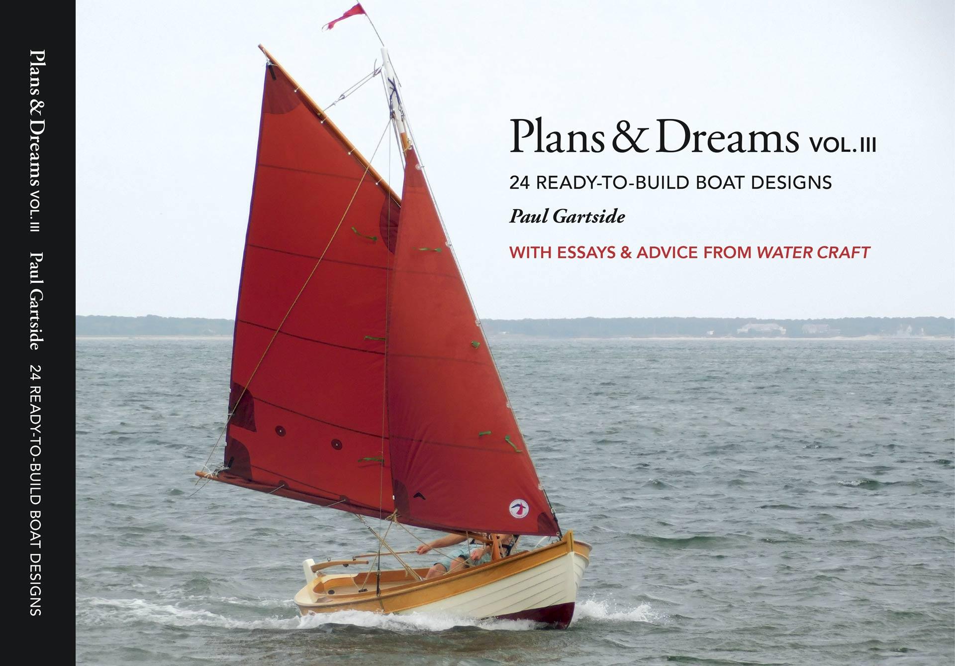
Paul Gartside
WITH ESSAYS & ADVICE FROM WATER CRAFT
Plans & Dreams, Volume III
24 Ready-to-Build Boat Designs
ISBN 979-8-218-46636-7
Copyright © 2024 Paul Gartside.
Previous Volumes:
ISBN 978-0-692-15504-2 (vol. 2 © 2018)
ISBN 978-0-9938994-0-9 (vol. 1 © 2014)
Library of Congress Control Number: 2024916560
Cataloguing in Publication Gartside, Paul.
Plans & dreams. Vol. 3, 24 ready-to-build boat designs / by Paul Gartside ; with essays and advice from Water Craft. -- 1st edition.
192 pages 9 in. x 11.875 in.
1. Boats and boating--Design and construction. 2. Boatbuilding-Amateurs’ manuals. I. Title. II. Title: Plans and dreams. Vol. 3, 24 ready-to-build boat designs. III. Title: 24 ready-to-build boat designs. IV. Title: Twenty-four ready-to-build boat designs. V. Title: Water craft.
VM321.G37 2024 623.82’02 QB114-600149
All rights reserved. Except for use in review, no part of this book may be reproduced or used in any form, electronic or mechanical, including photocopying, without written permission from the publisher. Permission requests should be addressed to the publisher at the address below: Paul Gartside
29 Malone Street, East Hampton, NY 11937 USA www.gartsideboats.com
Book design and layout by Rami Schandall / Visual Creative. Edited by Stuart Ross.
Printed in Canada by Friesens Corporation. All chapters have appeared in Water Craft magazine. First edition: October 2024.
Chapter 1. 16 ft. Centreboard Yawl Sweet Dreams
#226A With a description and photos of light, edge-glued carvel planking.
Chapter 2. 25 ft. Tancook Whaler 14
#227 A close look at an interesting historic model from Nova Scotia and a eulogy to the work of marine historian Howard I. Chapelle
Chapter 3. A Small Diesel Motor Launch 22
#228 A practical 6.50 m cabin launch of simple strip construction. A discussion of the difficulty of obtaining good boat lumber.
Chapter 4. 24 ft. Light Sloop
#229 Double-ended light sloop, with thoughts on the necessity of sustaining enthusiasm and stamina through large projects.
Chapter 5. 15 ft. Long Island Clamming Skiff
#230 Flat-bottomed skiff, with notes on the delights of simple traditional construction techniques and the visual power of even the simplest boats.
Chapter 6. A Miniature Pirate Lugger 44 #231 10 ft. sailing dinghy, designed with and for a young designer/builder.
Chapter 7. A Dream of Escape, 29 ft. Motor Sailer Long Shot 51 #232 An interesting request results in a unique vessel with more than a nod to Slocum’s ‘Spray.’
Chapter 8. 14 ft. Plywood Rowboat 60
#233 Inquiries from two islands on opposite sides of the planet provide inspiration for the design of an efficient rowboat, a plywood peapod.
Chapter 9. An Imaginary Voyage, 18 ft. Shanty Boat 65
#234 A request for a simple shanty boat for use on sheltered water leads to a voyage of the imagination through the heart of America.
Chapter 10. 30 ft. Double-Ended Schooner 72
#235 Tancook schooner, with thoughts on wood boat construction in the tropics and the proper sizing and installation of propeller shafts and bearings.
Chapter 11. 45 ft. Cutter 79
#236 A reworking of a much-loved earlier design, with thoughts on the trials and triumphs to be found in larger projects
Chapter 12. 24 ft. Sloop, a Practical Cruiser 88 #237 Includes thoughts on single-handing and self-steering of long-keeled boats.
Chapter 13. Unusual Motor Sailer, 16 ft. Gozzo Boat 96 #238 An unusual small motor sailer based on the beach boats of Greece and Italy.
Chapter 14. 4.9 m Cutter Pudel 104 #239 A small cutter, first developed as a stock boat in 1978, encapsulates the appeal of the miniature yacht. Reimagined here for traditional carvel on bent frame construction.
Chapter 15. 15 ft. Garvey
113 #240 Simple and practical, a small workboat for all manner of uses on and around the waterfront.
Chapter 16. Miss Greta 117 #241 21 ft. 6 in. electric launch, with notes on the necessity of moving away from the use of fossil fuels in boats and the benefits and challenges of electric power.
Chapter 17. 18 ft. Clinker Launch
125 #243 A fine husky launch of traditional construction and diesel power. Contains a detailed building sequence and tips for quality clinker work.
Chapter 18. 13 ft. Catboat Crisis
133 #246 An easy-to-build, plywood catboat, small enough to be put together in the garage from readily available material
Chapter 19. 17 ft. 6 in. Garvey Zoom
140 #247 A larger version of the 15-foot garvey in Chapter 15, detailed for double-skin glued construction with the option of clinker topsides. An easy boat to build and enjoy
Chapter 20. Bud Baker’s 16 ft. Double-Ended Rowing Skiff
146 #242 When in doubt, build a double-ended rowboat. Designed and built in 2020, this is a good all-round model that can be used with one or two rowers.
Chapter 21. 14 ft. Double-Ended Skiff Skraeling
153 #260 A smart, fast daysailer, with musings on the enduring legacy of the Norse aesthetic in the field of boat design.
Chapter 22. A Motorboat for the Adventurous
161 #245 34 ft. motor cruiser, a capable long-distance motorboat of simple construction, with thoughts on the importance of maintaining an understanding relationship with one’s engine.
Chapter 23. 19 ft. Centreboard Sloop
169 #257 One of the sweetest daysailers in our series, with musings on the enduring appeal of the double-ended model .
Chapter 24. Ditch Witch
178 #225 18 ft. 6 in. centreboard sloop, in which we revisit the very first plan drawn especially for Water Craft readers in 2008 to ponder again the delights of minimalist cruising.
Volume III of Plans & Dreams contains two dozen plans drawn between the years 2017 and 2021 that were first published, along with the accompanying essays, in Water Craft magazine in the UK. Most of these plans were commissioned directly by readers of the magazine as home-build projects. Readership is worldwide, so the chapters contained here reveal an interesting perspective on the desires and daydreams of the amateur boatbuilder in this period. There are clearly themes and recurring veins of interest, and, of course, fashion plays a role here, as it does in every aspect of our lives. Frequently one plan sparks the next, so there is a constant process of revisiting and reimagining. Chapter 1 is a good example of this and brings the happy realization that there is no perfect boat—it is in fact a bottomless well.
Note that while the majority of the plans in this collection are drawn in imperial units (feet and inches), a couple are in metric. The choice of units is made by the original customer, and since most are in the USA and UK, imperial predominates. My advice is always to work in the units a plan is drawn in rather than attempt to convert. I don’t know that either system can claim superiority, and it doesn’t take long for the brain to adjust.
It was, of course, in these years that we were struck by the Covid-19 pandemic. It left its mark on both our lives and on this series of plans and essays. Chapters 18 and 19 bore the brunt, and I have retained the real-time references to it in both the design names and the text. The pandemic feels very distant five years on, but I think it important not to forget either the disruption it caused or the sustenance so many of us drew from our creative outlets through those difficult days.
I am naturally selective in the boats that get developed into plans, picking only those vessels with which I feel some empathy, so not too many fast motorboats or exotic materials. In fact, all in this collection are of wood construction of one kind or another. Traditional rigs are favoured mostly because they are simple to make. All plans require
the purchase of some items of stock hardware, even if it is just the oarlocks, but an objective of the series has always been to keep the catalogue expenditure to a minimum in the belief that making is more enjoyable than buying.
Wood is the natural material for small-boat building—natural in all senses. It is far and away the most pleasant to work with and endlessly interesting in grain, texture and history. While I casually note dimensions and species on the plans, I do so knowing full well that no two pieces of wood are ever alike, and it will fall to the builder to select appropriately from their inventory the right pieces for the various components of the structure, finding suitable alternatives where necessary.
Rereading these essays, I am pleased to see how often I have stressed the importance of buying locally—almost, I fear, to the point of tedium. Not long ago it was the norm to plunder the forests of the equatorial regions for high-grade boatbuilding material. The yachtbuilding industry of my youth was built on that practice. In the list of species deemed suitable for yacht construction in my 1966 copy of Lloyd’s Rules for the Construction and Classification of Wood Yachts, two-thirds belong to the tropical regions, and the majority are now, in 2024, commercially extinct. A handful are still available from plantation sources, though these are generally of poorer quality than first-growth. The trajectory is clear and such that I am increasingly uncomfortable using any wood grown in African soil or, for that matter, Indonesian or Amazonian. Better that those trees remain intact and a living part of the ecosystems they belong to than dismembered in my workshop.
Which is not to say I think our purposes trivial—far from it. I believe the enjoyment that boatbuilding provides and the nourishment it brings to lives increasingly divorced from sustaining manual work is priceless. It is soul food at its best. All the more reason, then, to avoid the taint of ecological damage on the other side of the world.
While yacht work has always leaned heavily on tropical species for quality as well as for status, working craft by contrast are almost always built with local materials. In the UK and Europe, oak, elm, larch and Baltic red pine predominate. In the US, it’s white oak, white cedar, white pine and Robinia. And in the Pacific Northwest, Douglas fir, western red and yellow cedars. Some areas are clearly more blessed than others, but there are very few places where it is impossible to pull together enough material locally to build a small boat. It helps that with modern glued construction we are no longer as reliant on the large clean lengths of timber, and it is easier to make use of secondgrade stock. Local sourcing brings its own rewards too, in particular the relationships it fosters with local sawmills and the understanding and appreciation of proper resource management. Clearly this is the approach we need to take now.
The same thinking should apply when it comes to choosing plywood, which in many ways is the everyman’s material—available everywhere and consistent in quality and characteristics. For small, simple boats, and as an introduction to boatbuilding, plywood is a natural choice. It is a fact that the continuous growing seasons found in the tropics produce more uniformly grained veneers and, in turn, panels with more stable surfaces than species grown in the temperate regions, where the difference between summer and winter growth produces clear annual rings prone to checking in rotary-cut veneer. However, marine-grade Douglas fir or pine plywood from Scandinavia is perfectly acceptable for our purposes. With a skin of light glass cloth and epoxy resin to stabilize exposed surfaces, it will last as well as anything. It is worth noting too that Douglas fir from the west coast of North America is more decay-resistant than the currently popular Okoume taken from the Gabon and other forest remnants in the Gulf of Guinea.
In putting Volume III together, my thanks go first to the staff at Water Craft magazine for the unfailing quality of reproduction of the plan sets I send over to them every eight weeks—as often as not, hard up against their deadline. And to our stalwart editor, Pete Greenfield, for his support over many years, as well as his ability to trim my rambling prose to fit the available space—with barely an argument in all the time we have worked together.
For this collection, I have gone back to the original essays, so here and there you’ll find a little extra material that was cropped from the magazine pieces. The time lag between first publication and this collection also allows for the inclusion of photos where boats have been built in the interim. Good boat photos are hard to come by, and taking them is very much a skill in its own right—the vessels are so close to living things. Yet I never feel a project is fully complete until we have captured something of that live spirit in a few still images. I am therefore doubly grateful when builders have the time and persistence for that final step. It always feels like a circumnavigation completed when months—sometimes years—after drawings leave the office, those compelling images come back.
Finally, big thanks to Rami Schandall at Visual Creative in Toronto, Canada, who is entirely responsible for the look and feel of the book you are holding (as well as that of Volumes I and II ). Without her talent, we would all be the poorer. Thanks too to Stuart Ross, rigorous copy editor on all three volumes. Any errors in the drawings or the offset tables are mine alone. Do let me know if you find one.
Paul Gartside March 2024
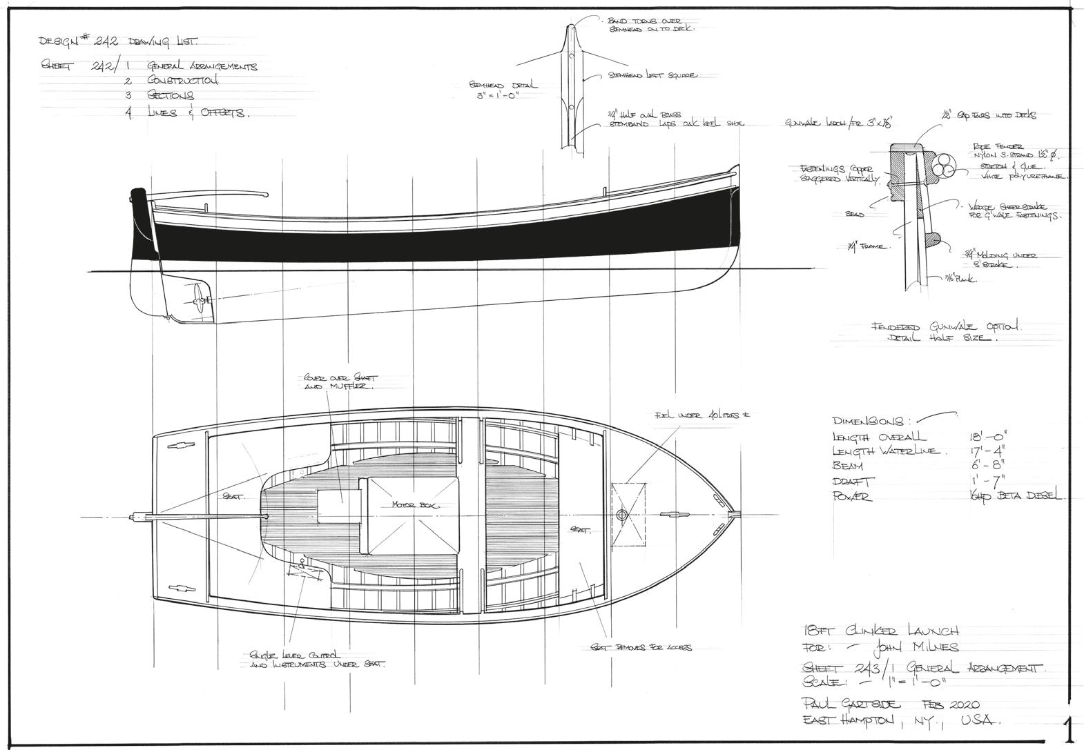
18 ft. Clinker Launch
Length Overall
Length Water Line
18 ft. (5.50 m)
17 ft. 4 in. (5.27 m) Beam
6 ft. 8 in. (2.03 m)
Plans & Dreams, Volume I, Chapter 16, contains plans for an 18-foot Gentleman’s Launch drawn for John Milnes, retired submariner and enthusiastic builder of small boats. I thought it just the ticket for both customer and brief, but alas it missed the mark and so far as I know has yet to be built. It’s a funny thing how personal the images of the boats we carry around in our heads are, and how often close just doesn’t do it. However, John has decided to give me a second chance at it, so here goes, with hopes that this time the fuse gets lit.
This is a simple boat and a very practical one too, ideal for work or pleasure use, a good spec project, the kind of boat that will always find a willing buyer. I’ve drawn it for traditional construction—clinker planking on bent oak frames. John is contemplating glued plywood lapstrake, which I think would be a pity. While in some ways a practical choice for the home builder, it is not nearly as much fun as real boatbuilding and to my mind doesn’t match the character of a boat that has waterfront workboat written all over it. With that diesel engine thumping away merrily, the more heavy-duty structure just feels better to me. So let’s set up the steam box, immerse ourselves in the joys of real boatbuilding and hope we can bring John along with us.
We’ve covered clinker building in some detail in these columns in the past, but we can look at some aspects specific to this boat. The
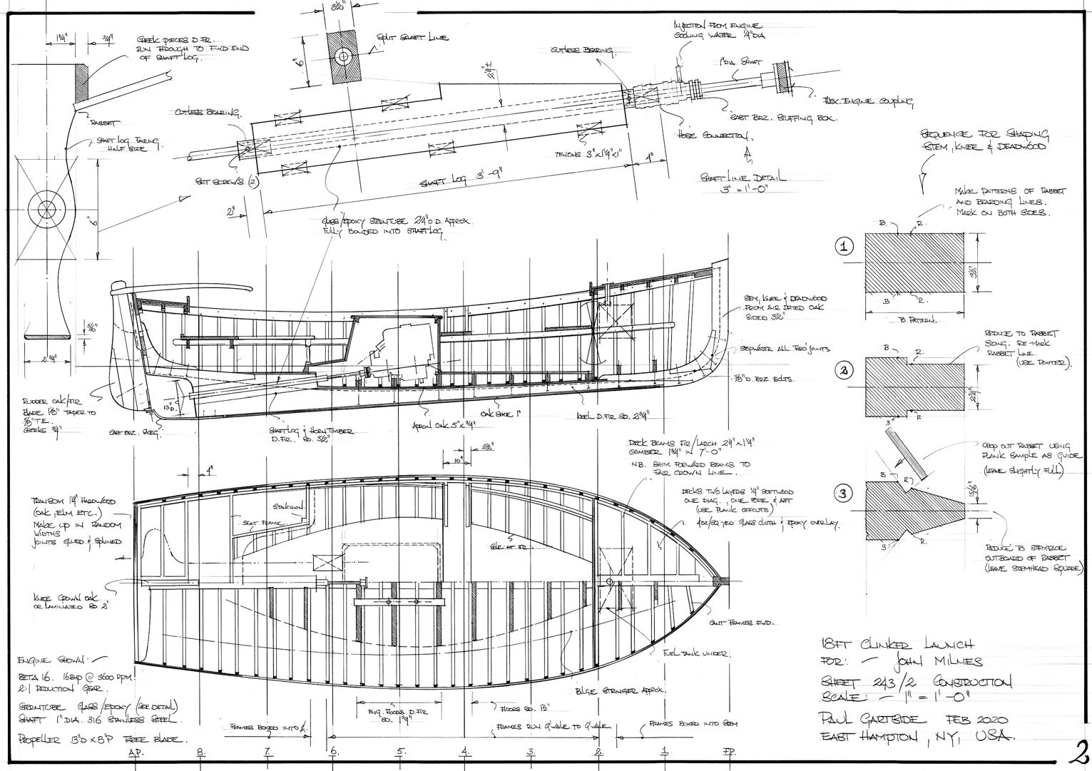
drawings are heavily detailed (maybe overly so, but the tricks and dodges they illustrate should help smooth the way for the first-time builder). We are using an upside-down set-up: frames bent first, followed by the planking. This is the reverse of the more common British practice of plank first, frame second. But there are advantages to this approach, especially for the builder, who avoids stooping and bending.
A careful full-size lofting is the first step; then, with body sections established, we will make the appropriate deductions to arrive at the shape of moulds. Since we will be bending frames first before planking, we must subtract from the outside of plank line the thickness of plank plus frame plus temporary fore-and-aft ribbands, for a total deduction of 115/16". See sheet 3 for that detail. The deduction will be constant on all moulds, though in theory we should take a little more fore and aft of amidships as the plank angle changes. A constant deduction gets us close enough. The moulds are extended to the building base, where a cross pall is fitted for an easy set-up.
Next we will make up and assemble the components of the centreline—keel, stem, shaft log and horn timber. Stem, knee and fore deadwood will be air-dried oak bolted up with nice tight joints wellbedded. Once the rabbet is cut and the stem shaped per the detail on sheet 2, stopwaters will be fitted on all through joints. For the keel, log

and horn timber, I’ve shown Douglas fir. That is determined by the stern tube arrangement. I’m using a glass/epoxy tube that will be fully bonded into the shaft log. For that we need wood with good gluing characteristics. Fir would be my choice, but there are other options. If a bronze tube is used, we could use an all-oak centreline, the time-honoured material. In that case, we need to bore for the stern tube—pilot hole first, reamed out later, with the boring bar to clear the outside diameter of the tube. I prefer an inert glass tube bonded in with thickened epoxy that becomes part of the structure—it’s simple to make and will be there long after all else has turned to dust (designer and builder included).
With the backbone assembled, it can be lowered gently into the mould notches, pulling everything into its rightful place and solidifying the building jig. The permanent stringers go in before framing and serve as part of the bending jig—so much easier than fitting
First-class workmanship in John Milnes’s spotless workshop. Note the details of the set-up: frames bent outside the ribbands with heels boxed into the stem. Lining out battens for the planking have just been placed. Battens are the same width as the plank land.
Photo credit: John Milnes.
them later. Both bilge stringers and gunwales will require steaming, and note too that the gunwale will have to be sawn to shape. The full deck line will give it a pronounced S curve that can’t be overcome by steaming alone. We’ll take a spiling and cut it out just like a piece of planking. Try to avoid short grain at the forward end, and if it has to be scarfed, keep the joint well aft so it doesn’t have to go in the steam box—it’s the forward half we need to limber up.
Temporary ribbands go on next, filling the gaps between stringers and keel. Note the jogged fids used to secure these to stem rabbet and transom. It’s worth going over the jig with a batten at this stage and knocking off any high spots before bending the frames—put a slight round in the back of the bilge stringer so there are no hard spots. The ribband next to the keel will have its corner removed so the frames fair through nicely onto the apron. All these little dodges make for a stress-free bending day.

Frames are in a single length, gunwale to gunwale, in the mid-body, then in two halves boxed into the centreline toward the ends. It is best to bend the long frames first so that breakages can be used up fore and aft, and for the same reason do the hard bends first, leaving the easy ones till last. The key to successful framing is to have the right material. We should look for straight, clear-grained oak from young trees and not too dry—half green is okay with me. Pay attention to grain orientation, particularly for the hard bends. Annual rings should be parallel to the hull surface.
Once it’s framed, we can fit wedges, as shown, to give the garboard a solid land. Later, when we are ready to put the sheer strakes on, we’ll do the same there to take the through fastenings for the gunwale. Both items connote quality construction. We’ll go over the backs of the frames with a batten and spokeshave, removing any high spots and adjusting bevels where needed. Then a coat of paint or varnish
Beautiful plank lines evenly spaced, the test of a good builder. Extra width in the sheer strake allows for the depth of the outer rub rail.
Photo credit: John Milnes.
on them, and we are ready to line out for planking. This is done on one side of the boat only, with light battens the width of the plank lap so we have a visual check on the final appearance before any planks are cut and hung. When we’re satisfied with the plank lines, they are duplicated on the other side of the boat and the marks faithfully adhered to as planks are spiled and cut.
The trick to spiling clinker planks has been discussed before but is worth emphasizing. Edge set is to be avoided in clinker work. While carvel planking can be sprung into place, driven up with clamps and wedges, we can’t do that with clinker planking. It causes them to pull away from the frames and open the laps, which leads to general grief all round. We want them to wrap naturally around the jig without edge set. Accurate spiling is the key, with the spiling batten closely replicating the plank position. Run off some ⅛" x 3" thin pine and tack two or three pieces together on the boat with a hot glue gun
so it lands properly on the lap of the previous plank. That way, the measurements taken and marked on it will be accurate. Sometimes a plank will spring when it is cut—wood is like that. If I find that happening, I will cut them a little oversize for extra wiggle room and adjust as they go on the boat.
A couple of thoughts on the shaft line and engine installation. To provide adequate support for the 1" diameter shaft, there is a waterlubricated bearing at both ends of the tube, the inner fed by a bleed from the engine-cooling water. The engine coupling is close enough to the inboard end of the tube that I’d like to see a flexible coupling fitted. I don’t often do that, but the geometry of this one dictates it— I would be concerned otherwise about wear in the forward bearing. This should not be seen as a substitute for careful alignment. Line up with the feeler gauges in the normal way, then part the couplings and install the flexible connection. Proper shaft support and precise alignment are the best insurance against drivetrain issues.
A bearing at either end of the tube makes life easy for the builder, as we can run a dummy shaft in there to give us the line of the beds; no need to fool around with a stretched string. The beds are notched down into the heavy floor timbers, which must be fully fitted to the planking, and they must bear solidly on the frames. Both those operations require careful fitting. Taking the floors first, make a light
pattern out of thin stuff fitted over the plank laps. Bandsaw the floor with some extra height and do a test fit. It will be miles off because no account has been taken of the bevel (not so much a fit—more of a seizure, as dear old Frank Andrew would say), but don’t worry. Brush a little wet paint on the planking, drop the floor down again, lift it out and, with a sharp chisel and spokeshave, remove the paint marks. Repeat and repeat for a half-hour or so and you can’t help but get a perfect fit eventually. It’s hard on the knees in the bottom of the boat, but just go slow—we are not trying to make this pay. The beds are notched into the floors both ways and bear on the frames. Use the same method to achieve good fits there. Again, leave them high and cut down once fitted. Beds can be glued and lagged into the floors, or for small installations like this, I like to pin them with big oak dowels like a trunnel fastening. That way there is no concern about hitting a bed bolt with the engine feet bolts. (Been there? Me too.)
This promises to be a most enjoyable project. It is all boatbuilding, with very little of the tedious fitting-out work that comes with larger projects. The richness of traditional construction is the main appeal. From the sourcing of material and the relationships forged with local sawmills and their colourful inhabitants, to the smell of the fresh-cut timber, fragrances that reach back through generations of boatbuilders, to the smoke and hiss of the steam box—it’s all an intoxicating magic.
Detail from sheet 2: shaft line and engine installation.
19 ft. Centreboard Sloop
Length on Deck
Length Waterline
Beam
19 ft. 0 in. (5.8 m)
16 ft. 10 in. (5.13 m)
7 ft. 4 in. (2.22 m)
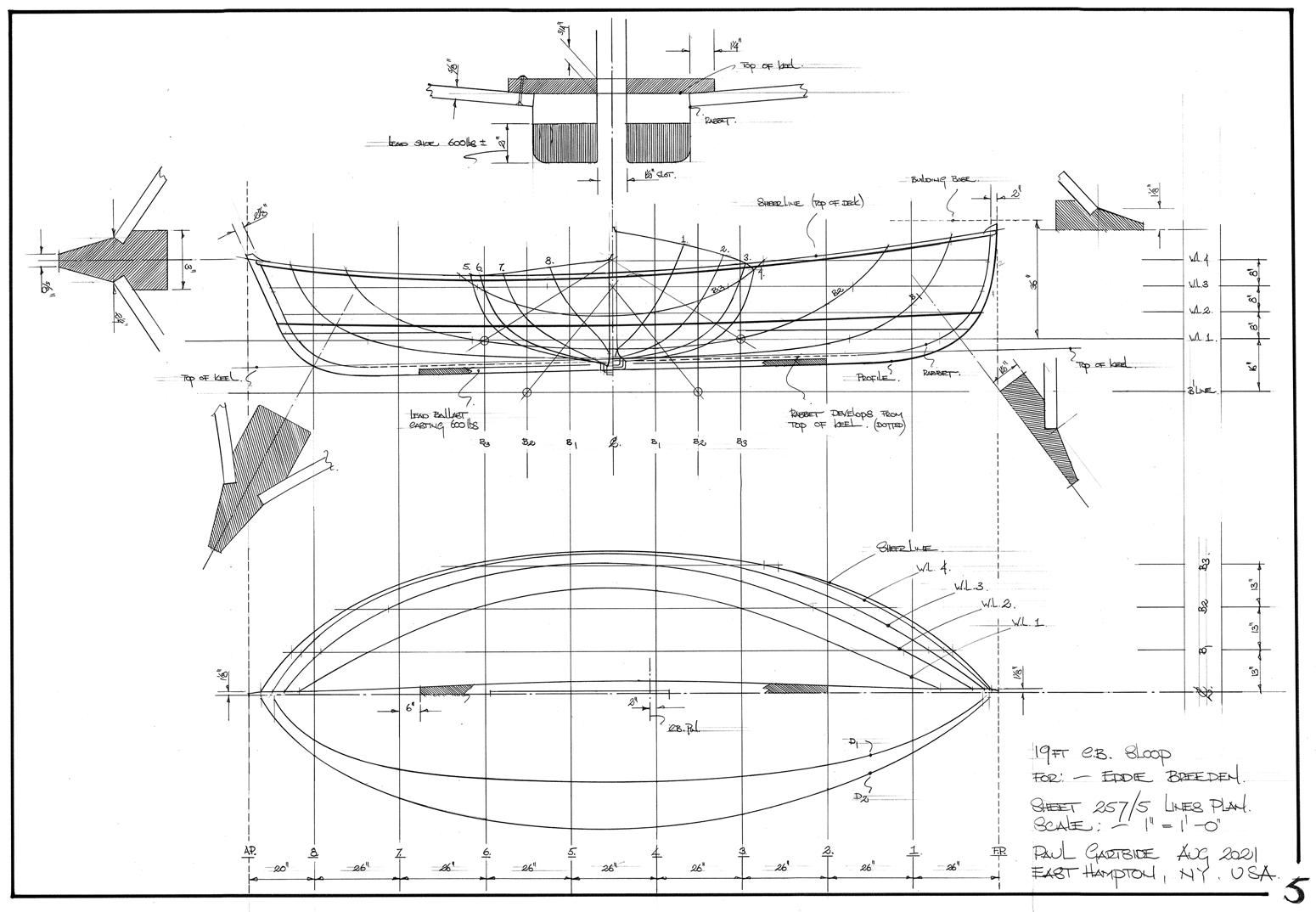
Somewhere back in the late Middle Ages, when this series began, we published the plans for a 16-foot double-ended sloop, design #165. It was the first of a string of small centreboard double-enders we have featured in the years since. For reasons not entirely clear to me, this general model remains by far the most popular of any of the types we have explored. The simple power of symmetry, I suspect, overcoming rational argument. For we give up a lot when we sharpen both ends of a hull, especially in small boats. Right away we lose a chunk of righting moment and hence sail-carrying power—a transom stern is much more effective in this regard, and offers planing potential in strong winds. It is also harder to arrange for auxiliary power in a doubleender. A small electric outboard mounted on a removable bracket over the side is probably the best solution for covering distance; otherwise, a pair of sweeps or the Chinese solution, the long cranked yuloh, worked in a pivot offset to one side of the rudder.
But if we know anything about the science of boat design, it’s that it is not a science at all, but rather a conversation with some entirely different part of the brain, a luxuriant place of daydreams and distractions where rational argument is often an unwelcome intruder. Perhaps that’s why books on design theory are often so unsatisfying. Sure, we know the numbers are important—in any kind of competitive environment, essential—but surely there is more to it than that?
Draft (Centreboard Down)
Sail Area
Ballast
4 ft. 3 in. (1.3 m)
190 sq. ft. (17.66 sq m)
600 lb. (273 kg)
A hundred and fifty years ago, Walt Whitman described that feeling of disappointment perfectly in his poem “When I Heard the Learn’d Astronomer.” I still remember the recognition and relief I felt when I came across that one. But we are wandering again.
A nice example of plan #165 is Skorri , built by Rob Denny in Saanichton, British Columbia. Rob added a cuddy not shown on the original drawings that seems to suit her well and attracted the attention of Eddie Breeden, confirmed double-ender man who boats on Mobjack Bay on the Chesapeake. Eddie’s thoughts went to a larger version with cockpit space for four and a similar cuddy to keep gear dry and make sleeping aboard a little less spartan. That brief forms the basis for this chapter’s plan.
Skorri , at 16 feet, is at the upper end of the size range for an unballasted boat, particularly single-handed, and I was a little disconcerted to see Rob had omitted the tiller extension I would have deemed indispensable for hiking out. For Eddie’s boat there is no question some fixed ballast is required. Just how much is something of a judgment call, but the 600 lb. shown on the drawings feels about right and should power her up nicely. Proper disposal of crew weight will still be very important, and early reefing is recommended when single-handing.

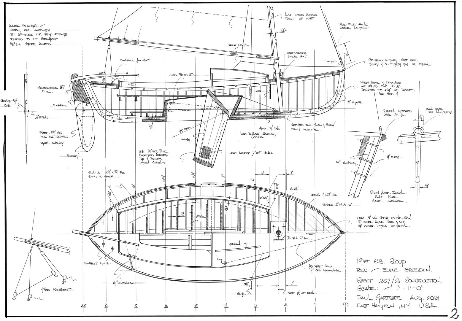
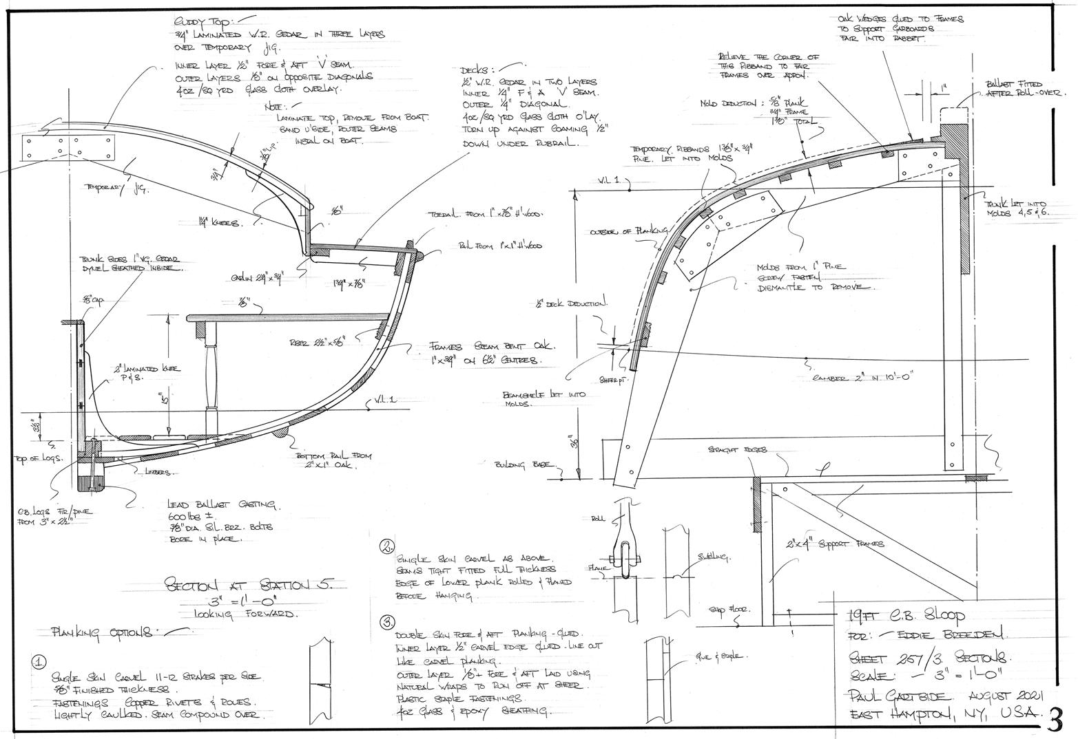
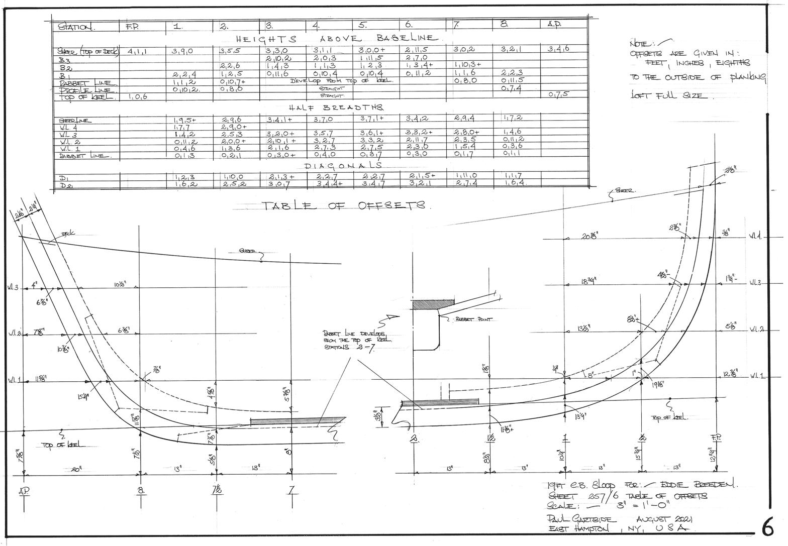
The construction drawings show simple carvel on bent frames, the most pleasant way to build if good planking material is available. Here in the US, the cedars, western red or Alaskan yellow, would be the best choices. I would use a standard caulking seam two-thirds of the plank thickness deep and gently set a single thread of cotton topped with seam compound. Another approach that works well with softwood species is the rolled seam described in Plans & Dreams, Volume I, Chapter 2. For those seeking the elusive (and overrated) dry bilge, a fully glued option is also given on sheet 3. I am not sure where Eddie stands on epoxy use, but this double-skin method uses the least amount of it for a tight, stable hull.
I’ve shown the stem and sternpost in some detail and had a good time doing it. Assembling and shaping up a proper rabbeted stem in air-dried oak is one of the most enjoyable parts of the boatbuilding process, and even on paper is good fun to work through. In glued construction we often plank up over an inner stem, plane off and fit the outer stem as a separate piece. Practical, perhaps, but not nearly as much fun or as fragrant.
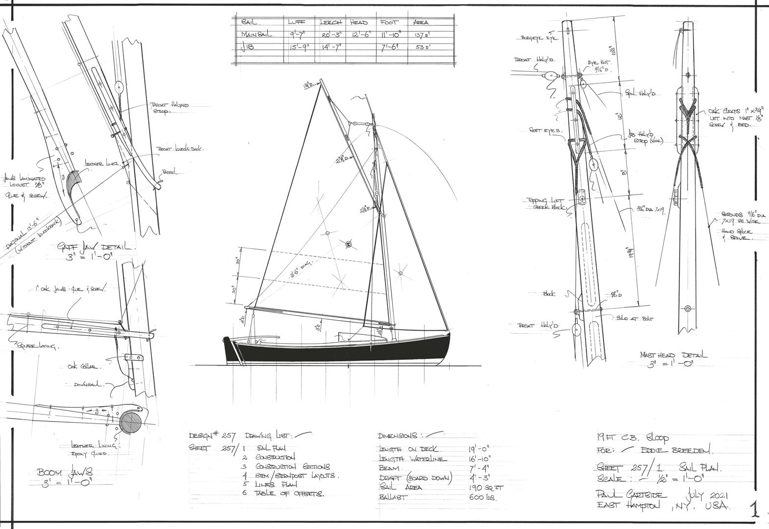
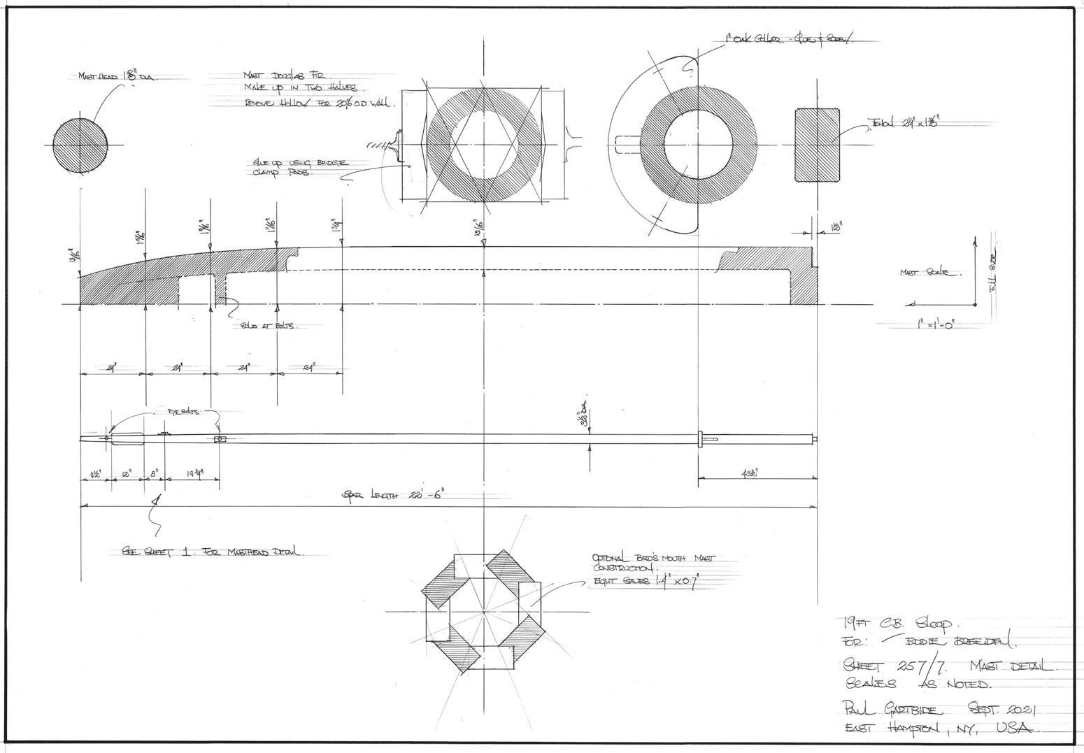
The rigging is as simple as it gets: a hollow mast to make stepping easier, a solid boom and gaff with hardwood jaws. Standing rigging will be 3/16" diameter, with a 7" x 9" wire set-up and lanyards rather than rigging screws. The soft eyes at the masthead and the thimble eyes at the lower end will look best hand-spliced, served and varnished. Don’t forget to parcel under the serving with cloth-based electrical tape—which I am happy to report we can still get here in New York. Who said America is in decline?
Rob Denny of Brentwood, British Columbia, built his 16-foot ‘Skorri’ to design #165 featured in Chapter 8 of ‘Plans & Dreams, Volume I.’ Rob added the neat cuddy, and it was this photo that served as inspiration for the 19-foot boat in this chapter. Photo credit: Nighean Anderson.
