
ACOUSTIC
SID: 140442252 WING ON TSE ARC2010 ARCHITECTURAL TECHNOLOGY 2.2 THE 1:1 MATERIAL PROJECT REPORT
PANEL
POSSIBLE DESIGNS
REFERENCES
LIST OF FIGURES
2 CONTENTS PAGE 3 DESIGNING FOR THE MEDIUM
4
MATERIAL SELECTION PAGE
5
WASTE REDUCTION PAGE
PROCESS OPTIMISATION
6 DESIGNING IN THE MEDIUM
SUMMARY
PAGE
FABRICATION PAGE 7 ACOUSTIC PROPERTIES PAGE 8 MOISTURE PAGE 9 SCALE PAGE 10
REFLECTION PAGE 11
MATERIAL SELECTION
TYPE
Oak is a hardwood species commonly used in construction due to its strength, durability, and attractive appearance. In addition, oak is known for its resistance to decay and insect infestation, making it a popular choice for outdoor and wet environments.
SOURCING
As a native tree species to the UK, oak can be found in various regions nationwide. As such, oak can be sourced from many locations in the UK, including forests, woodlands, and commercial timber yards. These companies can be found throughout the UK. They may offer sustainably sourced oak certified by organizations such as the Forest Stewardship Council (FSC) or the Programme for the Endorsement of Forest Certification (PEFC).
DIMENSIONS
Sawn timber, particularly timber battens, is considered for producing this artefact as they are extensively used on most of the site creating frames of varying sizes and having a considerable amount of offcuts.
These are the standard dimensions (in mm), rough-sawn, air-dried:


24 x 30, 24 x 48, 27 x 35*, 27 x 40*,
27 x 50*, 27 x 60*,30 x 48, 30 x 60,
50 x 50, 60 x 60, 60 x 80, 60 x 100,60
x 120, 80 x 80, 80 x 100
*Western Switzerland (Deplazes 2008)
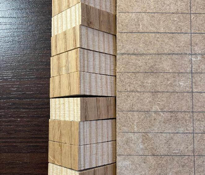
It has a light colour at most of the sides but I have noticed that one side has developed a patina, which is a change in color and texture due to exposure to sunlight or other environmental factors.
THE DESIGN SHOULD BE REPLICABLE IN MOST CONSTRUCTION SITES WITH THE LEAST AMOUNT OF CUTS AND STEPS.
3
FIGURE 1 This is one of the oak batten offcuts I have acquired from the APL workshop.
DESIGN PRINCIPLE
WASTE REDUCTION
Determine the project requirements
Reuse
Recycle
Disposal
Assess the available timber resources Select the appropriate timber species and grade for the project Prepare the timber for construction (cutting, shaping, treating) Construct the building using timber (beams, columns, walls, etc.) Inspect the timber for quality and durability
Maintain the timber over time (repairs, treatments, etc.)
Consider end-of-life options for the timber
Offcuts created
REPURPOSING OFFCUTS CARBON REDUCTION
Timber offcuts are found during the cutting of timber on a construction site. These offcuts are smaller pieces of timber that can be immediately reused on-site to reduce waste and save costs. Otherwise, they are recycled or considered as waste.
Temporary structures, bracing or blocking, or for smaller construction tasks can be ways where these smaller pieces of timber offcuts can be utilised. The more intricate pieces are usually disposed of as they are less useful. I want to address these smaller offcuts and create a functional product.
Utilising these offcuts can reduce construction waste. Less transportation and processing are required, leading to a reduction in carbon emissions. Also, less waste is sent to landfill sites, minimising environmental damage.
(Cobb 2014)

4
FIGURE 2 CIRCULATION OF ENGINEERED TIMBER
FIGURE 3 MAIN POTENTIALS FOR WASTE RECOVERY AND REUSE (COBB 2014)
PROCESS OPTIMISATION

SCALABLE VARYING LENGTHS


The design should accommodate offcuts that come in a variety of lengths. Minimising the size of the components could allow more offcuts to be used.

Timber battens with different footprints can be used for the design as there is little impact on the performance with different sizes.


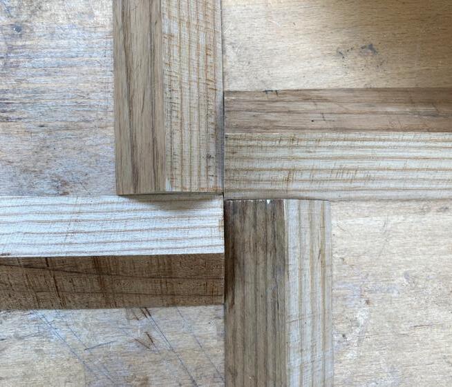
POSSIBLE DESIGNS
AVALIABLE FOR MOST SITES
SUSTAINABLE & EFFECTIVE
Band saws or, more preferably, circular saws would be the only machinery needed to fabricate this
By minimising the number of cuts and considering the limiting dimensions of the material, I can design an efficient fabrication process with minimal waste.
THIS IS THE THROUGHT PROCESS SHOWING HOW THE FINAL DESIGN DECISIONS WERE MADE.

5
FIGURE 4
FIGURE 5
FIGURE 7
FIGURE 6
FIGURE 8
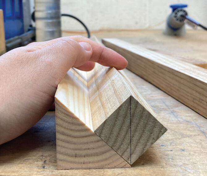
FABRICATION
LOCATION: WORKSHOP/INDOOR TEMPERATURE: 25.9°C HUMIDITY: 38%
STEP 1 CUT ALONG THE LONG SIDES
FIGURE 9
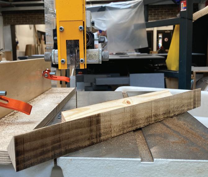
45°diagonal cuts are made on the 30mmx30mm offcuts with a jig and on the band saw.
STEP 2
CUT AGAINST THE GRAIN
FIGURE 10
20mm-wide triangular pieces are cut with the band saw.
REMARKS
USE OF A JIG (DURING STEP 1)
FIGURE 13
With the limited use of a circular saw which can allow tilted cut, technician Richard helped me create a jig that will enable the material to be temporarily attached to it with double-sided tape.
DIFFERENT BANDSAW (DURING STEP 1&2)
FIGURE 14
Saw burn marks are created due to the friction heating the blade. This could be due to its sharpness and cleanliness. I have switched to a second bandsaw with a newer blade afterwards.
STEP 3 PREPARE A BASE BOARD
FIGURE 11
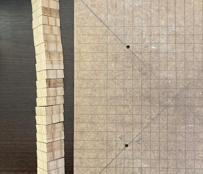
A minimum of 2mm board with the dimension of 300x300mm is made. Holes are pre-drilled for it to be wall mounted mechanically. 3mm MDF is used on this artefact.

STEP 4 ASSEMBLY
FIGURE 12
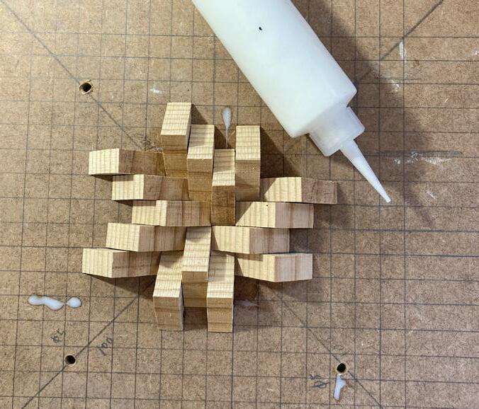
The components are arranged in a spiral pattern, glued with PVA glue, and sit for 2 hours to create the final product.
ALIGNING THE FACES (DURING STEP 4)
FIGURE 15
A patina is one of the reasons I have chosen these offcuts for the artefact, as they create further contrasts when assembled.
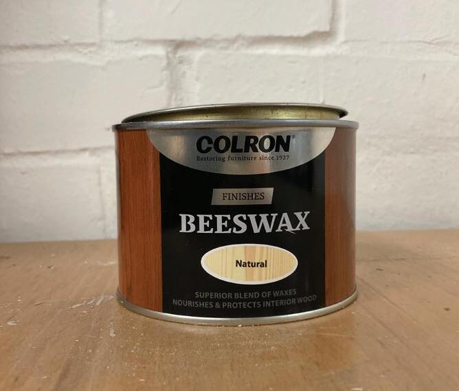
FINISHES (AFTER STEP 4)
FIGURE 16
Two layers of beeswax are applied with a cloth for a natural wood polish and conditioner. It can also act as a water-repellent for durability.
6 4-STEP PROCESS
ACOUSTIC PROPERTIES
MATERIAL
Wood has inherent acoustic properties, such as low resonance, which can contribute to better sound absorption. (Salenikovich and Fröhlich 1969)


SOUND ABSORPTION
The acoustic panel is designed to be mounted indoors to provide sound absorption instead of sound insulation. BS EN ISO 11654:1997ìAcoustics - Sound absorbers for use in buildings - Rating of sound absorptionî: This standard provides a rating system for the sound absorption of various materials used in buildings, including acoustic panels. It defines the sound absorption class (A to E) based on the sound absorption coefficients. (BS EN ISO 11654:1997)
Timber has a moderate level of sound absorption which is lower than acoustic foams or mineral wool. However, designing the surface into a spiral and spiky pattern can allow sound waves to penetrate the timber mass and dissipate better.

I have created a small enclosed space with a wooden shelf and felt, with one side of it being the back side of the panel, which is a smooth MDF texture. I then play a tone (440Hz) within the space and measure the decibels (dB) of the internal space. The experiment is then repeated with the textured side.
The result from the sound level meter shows an even decrease in the whole range of frequency from 73dB to 66 dB.

The panel is often perforated or textured to increase sound absorption. In this design, triangle bits are staggered in a herringbone pattern to absorb and dampen sound waves.
FORM APPLICATION
A series of panels can be mounted at auditoriums, theaters, recording studios, offices, and residential spaces, to enhance sound quality and reduce echo or reverberation.
ROOM REVERBERATION
Reverberation time (RT) measures how long sound persists in space after the sound source has stopped. With sound-absorbing materials such as timber, it will speed up the decaying process of sound. Adding acoustic panels enhances the clarity of sound, especially speech. (Hetreed, Ross, and Baden-Powell 2017)
An RT test requires an octave-band analyser, a calibrated loudspeaker and an empty enclosed room. If I were to test the panel, I would also have to fabricate a series of these compoenent to produce a significant effect.
7
Figure 18 & 19 with and without acoustic panel
Figure 20
The test result from the app ‘Decibel: dB Sound Level Meter’
EXPERIMENT 1
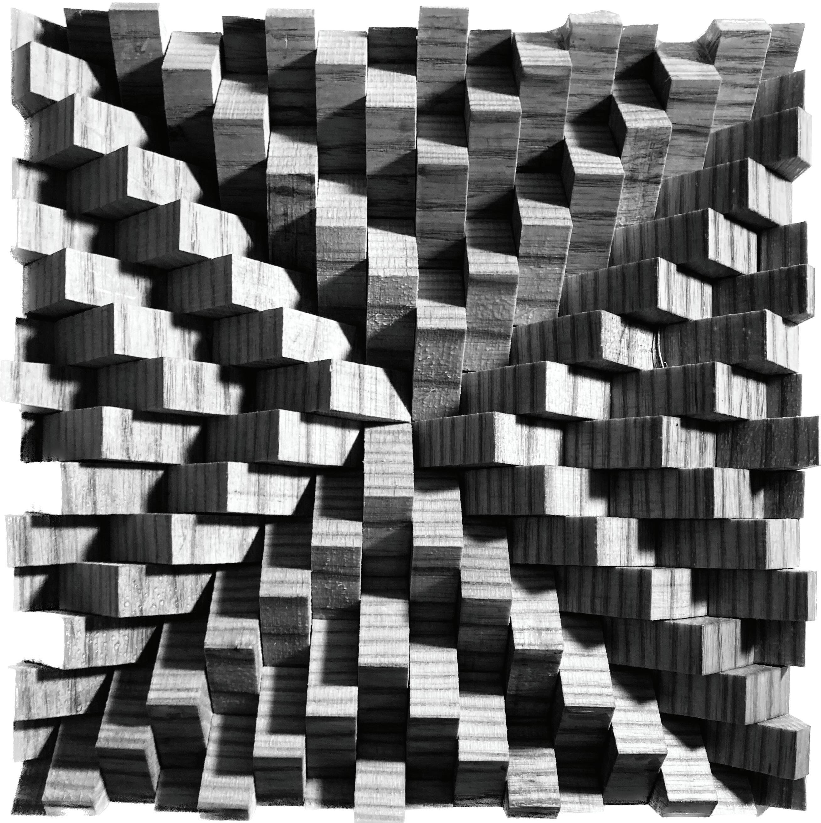
FIGURE 17 THE ARTIFACT ON AN OUTDOOR CONCRETE WALL SHOWING THE CONTRAST OF SHADOW AND
MOISTURE
MOISTURE ON FINISHING MOISTURE ON BONDING
Two coats of beeswax are applied to the panel’s surface as a protective coating for the oak to enhance its durability and appearance.
Beeswax has natural water-repellent properties. When applied to oak wood, it creates a protective barrier that helps prevent moisture from penetrating the surface. This can reduce the risk of warping, cracking, or other damage caused by moisture absorption.
It is also a more sustainable finishing than varnishes and polyurethane as it is a renewable resource. It is also non-toxic and chemical-free.
The oak triangular components and the fiberboard are chemically bonded with PVA (polyvinyl acetate) glue. It is not inherently moisture-resistant. However, an interior build like these panels provides adequate strength and durability where exposure to moisture is minimal.


Yet, wood glue would be considered a better choice compared to PVA glue when this is replicated on construction sites as it provides stronger bond strength and moisture resistence.

FIGURE 23
Figure 21
Another advantage of wood glue over PVA glue would be the longer work time which could prevent me from hammering some of the pieces into the pattern as the glue has set.

The steam experiment aimed at providing an exaggerated test simulating a moist and warm climate. A kettle and a thermometer-moisture meter were used.
Water was boiled for a consecutive 10 mins where steam reached the panel. The meter is placed slightly below the panel, and the reading showed a 7°C increase in temperature and a 37% increase in moisture.
A controlled photograph is taken of the panel showing it at 23.9°C and 45% in humidity, which is the normal state.
This is taken after the 10-min steam test, where deeper contrast of the grains and a bit of sheen appeared.

8
FIGURE 22
READING SETUP BEFORE
FIGURE 25
FIGURE 24
AFTER EXPERIMENT 2
SCALE
DEPENDENT ON THE OFFCUTS
There is a minimal difference in the scale of these panels as they all provide an uneven surface for sound absorption. It depends on the thickness and width of the batten offcuts. For my archetype, the offcuts have a 30mm x 30mm footprint; hence they are relatively small. (As shown on the left of FIGURE 26)
EFFICIENCY
However, in terms of efficiency, as the most time spent on fabricating these panels would be the assembly, larger offcuts are preferred.
ARRAY
Multiple panels are usually required to provide effective sound control. To reduce excessive reverberation or control specific frequency ranges, more panels may be necessary to achieve the desired acoustic result.
PLACEMENT
Ideally, acoustic panels should cover a significant portion of the wall surface to absorb sound reflections effectively. By considering the height of the listeners, the panels should be mounted at the corresponding height to address the reflections that impact the listenersí experience directly.
600 mm 300 mm 450 mm 9
FIGURE 26 AN ARRAY OF PANELS AT DIFFERENT SCALES
REFLECTION
In this project, I have gained valuable insights into the significance of understanding the fabrication process and material performance to ensure the final product’s successful completion. Specifically, my focus has been on exploring the properties of timber, including its tolerance levels and grain patterns, as well as the importance of precision in fabrication techniques.
Additionally, sustainability has been a critical consideration throughout this project. I have had the opportunity to investigate how offcuts of timber can be effectively utilised and repurposed throughout their life cycles, aligning with the principles of sustainable design and resource conservation.
The fabrication process considered the concept of ‘Conditions of Workmanship’ introduced by Andrea Deplazes, where the limitations of materials (varying length of offcuts), skill level and the tools and machinery (circular saw) available at the construction site are taken into account. (Deplazes 2008) However, after going through the fabrication process myself, I noticed the assembly of the herringbone pattern and the alignment of grains might be too labour-intensive, defeating one of my design principles, efficiency.
I have also encountered several challenges that required expert guidance throughout the fabrication process. The technicians in the workshop provided valuable advice and assistance, helping me overcome these obstacles and enhance my understanding of the intricacies involved in fabrication. An example would be how they suggested using a push-handle while cutting the strip into small repeating pieces. It minimises the geometric deviation, i.e. not having a perpendicular/curvy cut, from happening.
However, there are still deviations in width that hinder the assembly. I created a grid with pencil marks before the assembly, hoping all the pieces would align. However, as they were cut slightly larger, probably due to neglecting the thickness of the blade, they added up, and the grid could not help with the assembly. Some of them even have to be sanded to have them fit together nicely.
Overall, this project has allowed me to realise an ethical and sustainable design into an artefact focusing on detailed observations and variables. I can further understand the material and its intricacies by documenting my experimentation in such detail.

10
FIGURE 27
Several pieces have to be sanded due to the variation of width when cut on the band saw.
WITH TIMBER’S WARMTH AND NATURE’S TOUCH, THESE PANELS SING, THEY DO SO MUCH, ABSORBING WAVES, BOTH HIGH AND LOW, CREATING SPACES WHERE MUSIC GROW.
Figure 28
Shadows casted on the surface of the panels with different sizes
REFERENCES
BS EN ISO 11654:1997. “Acoustics - Sound absorbers for use in buildings - Rating of sound absorption.”
Cobb, Fiona. Structural Engineer’s Pocket Book: Eurocodes. Third Edition. CRC Press, 2014.
Deplazes, A. Constructing Architecture: Materials, Processes, Structures: A Handbook. Birkhauser, 2008.
Hetreed, J., Ross, A., & Baden-Powell, C. Architect’s Pocket Book. 5th ed. Routledge, 2017.
Salenikovich, Alexander P., and Franz Fröhlich. “Acoustic Properties of Wood.” Journal of the Acoustical Society of America 46, no. 1A Supplement (1969): 124. Accessed May 7, 2023. https://pubs.aip. org/asa/jasa/article/46/1A_Supplement/124/686143/Acoustic-Propertiesof-Wood.
Figure 1. Own photograph
Figure 2. Own diagram
Figure 3. Cobb, Fiona. Structural Engineer’s Pocket Book: Eurocodes. Third Edition. CRC Press, 2014
Figure 4. Own photograph
Figure 5. Own photograph
Figure 6. Own photograph
Figure 7. Own photograph
Figure 8. Own drawing
Figure 9. Own photograph
Figure 10. Own photograph
Figure 11. Own photograph
Figure 12. Own photograph
Figure 13. Own photograph
Figure 14. Own photograph
Figure 15. Own photograph
Figure 16. Own photograph
Figure 17. Own photograph
Figure 18. Own photograph
Figure 19. Own photograph
Figure 20. Screenshot from the app
‘Decibel: dB Sound Level Meter’
Figure 21. Own photograph
Figure 22. Own photograph
Figure 23.v Own photograph
Figure 24. Own photograph
Figure 25. Own photograph
Figure 26. Own drawing
Figure 27. Own photograph
Figure 28. Own drawing
11
LIST OF FIGURES
THE 1:1 MATERIAL PROJECT REPORT ARC2010 SID: 140442252 WING ON TSE


