

WEI-CHIEH WANG
Architectural Designer
WORK EXPERIENCE
Gianni Ranaulo Design
Project Designer
https://linkedin.com/in/arch-wangweichieh (626) 383-9145
Los Angeles, CA 90005
09/2023 - Present
Los Angeles, CA
• Binhai Bay Outlet (SD to DD) Dongguan, China | 1.16 Million sqft | Super Regional Shopping Center
• Managed the five-story main shopping mall (788,700 sqft), including interior design and landscape
• Provided parametric optimization and solutions for complex geometry, such as canopy and skylight
• Contributed to the design development documents, including floor plans, wall sections, and details
• Communicated conceptual ideas with the design principal through sketches, drawings, and models
• Apartments on Spring St (SD) Los Angeles, CA | 165 Residential Units | Low-rise Apartments
• Programmed spaces by type and area based on functional requirements and the client’s needs
• Determined building envelope configuration and circulations to comply with planning guidelines
• Performed research on building codes and regulations to ensure compliance
• Toulon Shopping Center (Pre-design) Toulon, France | 893,100 sqft | Commercial and Office
• Conducted space planning and block planning of a 594,200 sqft retail area
• Leveraged conceptual modeling and rendering for a 298,900 sqft office design
MHC Architects
Project Designer
• NTU Sky Bridge (SD to CA) Taipei, Taiwan | 1,250 sqft | Campus Sky Bridge
03/2019 - 06/2021
Taipei, Taiwan
• Conducted regular site visits and wrote field reports in the Construction Administration phase, ensuring compliance with design intent specifications and identifying potential issues early
• Assessed contractor’s proposals for material and product substitutions to ensure design compatibility
• Developed comprehensive implementation plans, cost estimation, project schedules, and detailed progress reports to ensure timely delivery and project efficiency
• Assisted in the production of all phases of architectural documents and specifications
• Long-Ci Community Center (SD to CD) Taoyuan, Taiwan | 19,950 sqft | Community Hall
• Managed the development and implementation of BIM protocols and standards across team members
• Led sustainability team to develop monthly client presentations to target EEWH Silver certification
• Coordinate with clients and public agencies weekly, utilizing verbal communication skills and graphic presentations to ensure project requirements were clearly understood and met
• Evaluated building construction systems, means and methods, and materials to ensure the project stayed within constrained project budget requirements
EDUCATION
Southern California Institute of Architecture
Master of Architecture
Tamkang University
Bachelor of Architecture
SKILLS
09/2021 - 09/2023
Los Angeles, CA
09/2012 - 06/2017
Taipei, Taiwan
• Revit, AutoCAD, Rhino, Grasshopper, SketchUp, Enscape, V-Ray, Abobe Creative Suite, Microsoft Office Suite
ADDITIONAL INFORMATION
• Languages: English, Mandarin
• Certifications: LEED Green Associate (Credential ID: 11548981-GREEN-ASSOCIATE)
BINHAI BAY OUTLET
PROFESSIONAL PROJECT
PROJECT INFORMATION
Architect: Gianni Ranaulo Design
Type: Shopping Mall (1,156,500 SF)
Location: Dongguan, China
ROLE Project Designer (Involved in SD and DD)
RESPONSIBILITIES
• Parametric Optimization
• Concept Rendering
• Facade Design
• Technical Drawings
• Consultation Coordination
ROLE ON PROJECT
Gianni Ranaulo Design proposed a shopping mall comprising three distinct areas: “Ring,” “Cluster,” and “Mall,” which together foster a new luxury lifestyle and shopping experience. I joined the project at the latter stage of the SD phase, primarily focusing on developing the five-story “Mall” section, encompassing 788,700 square feet, through to the DD phase. My role involved close collaboration with the LDI to adjust plans and elevations in compliance with building codes, which required meticulously examining structural and mechanical drawings to detail tectonic connections accurately. I also developed scripts to modularize and planarize the curved elements into a feasible design, such as the curtain wall and skylight. Additionally, I proposed several shading canopies at the outdoor junctions to enhance the overall architectural design.
PROGRAMS USED


I designed multicolored cable canopies to provide shade and enhance the landscape.


I developed a Grasshopper script to iterate the design concept.


APARTMENTS ON SPRING ST
PROFESSIONAL PROJECT
PROJECT INFORMATION
Architect: Gianni Ranaulo Design
Type: Low-rise Apartments (165 Units)
Location: Los Angeles, CA
ROLE
Project Designer (Involved in SD)
RESPONSIBILITIES
• Massing Study
• Space Planning and Programming
• Facade Design
• Concept Rendering
• Circulation Analysis
ROLE ON PROJECT
Situated in Los Angeles’ Chinatown, this apartment complex serves as a tranquil retreat, offering residents a peaceful living environment far removed from the city’s daily commotion. I was involved in the project from the pre-design phase, beginning with a massing study and transitioning to various unit types’ designs. My role in this project included space planning and programming tailored to the client’s requirements. Concurrently, I crafted a coherent circulation system to efficiently organize the movement of tenants and vehicles across different spaces. After finalizing the spatial layout, I proposed designs for the internal facade and courtyard. Additionally, I contributed to design decisions and assisted in producing presentation materials for client meetings, including site analysis, plans, sections, elevations, area matrices, and renderings.
PROGRAMS USED
Rhinoceros, AutoCAD, Enscape
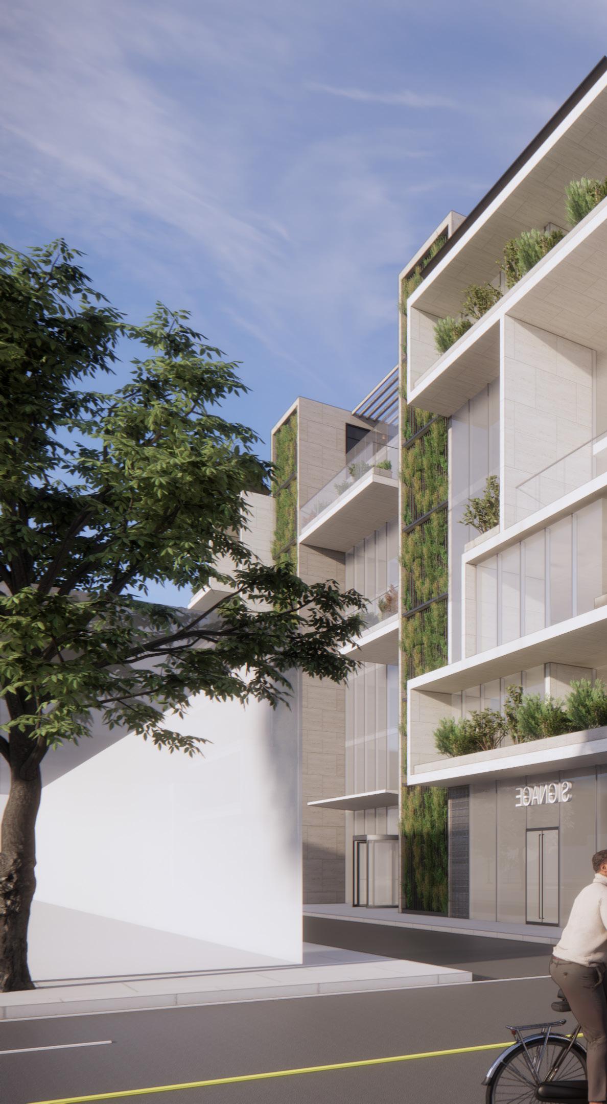

I assisted in the design proposal by conducting massing study, space planning, modeling, and Enscape renderings.


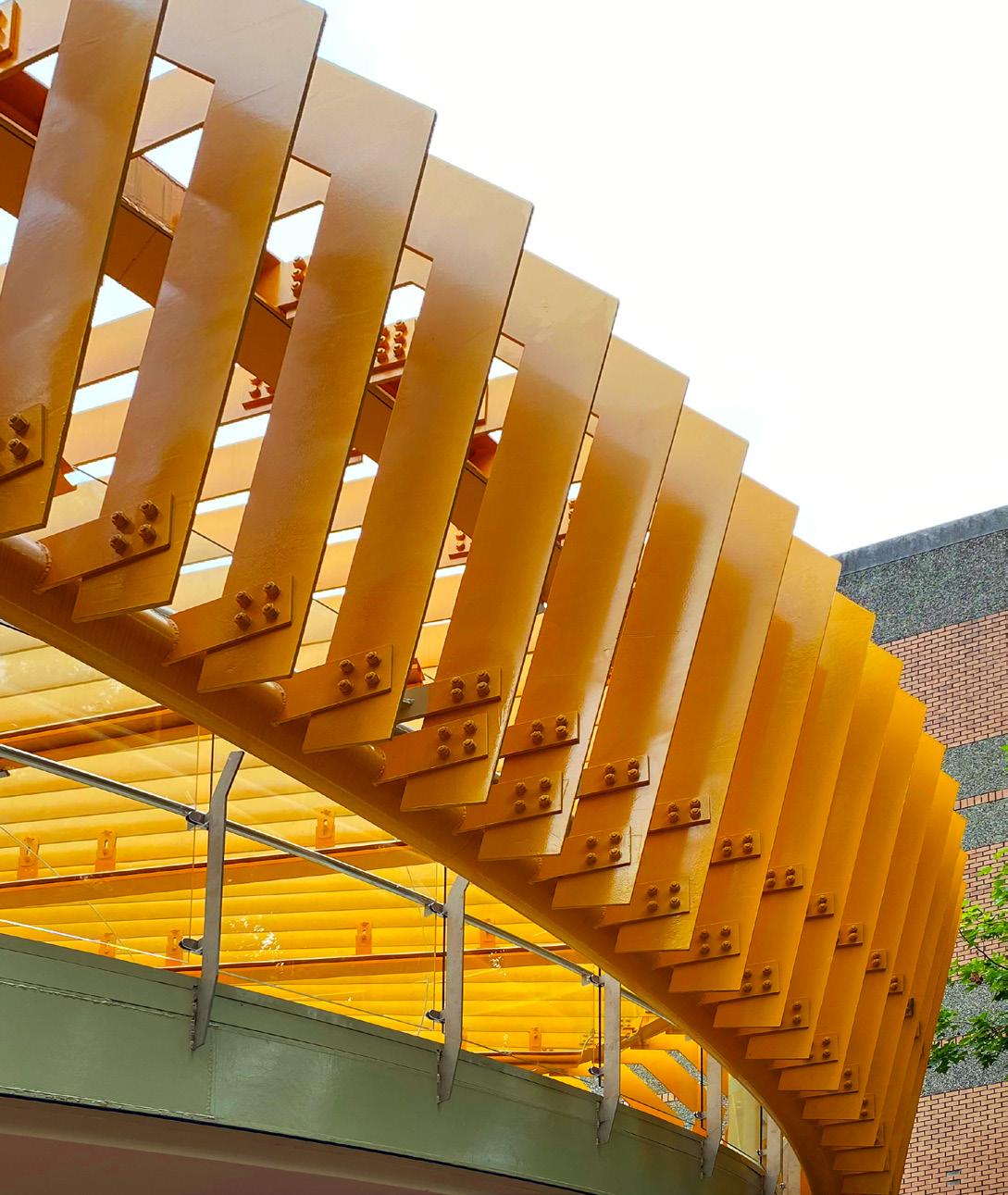
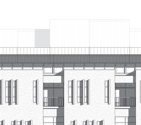
NTU SKYBRIDGE
PROFESSIONAL PROJECT
PROJECT INFORMATION
Architect: MHC Architects
Type: Institutional - University (1,250 SF)
Location: Taipei, Taiwan
ROLE
Project Designer (Involved in SD, DD, CD, Bidding, CA)
RESPONSIBILITIES
• Parametric Optimization
• Sustainable Strategies
• Detail Development and Specifications
• Client and Consultation Coordination
• Permit Set and Construction Documents
• Cost Estimation
• Site Observation
ROLE ON PROJECT
The skybridge connected the north and south halls of the Department of Psychology at National Taiwan University. I was the only designer working on this project. Therefore, I gained comprehensive exposure to all design phases, rapidly acquiring knowledge of the relevant codes and regulations. Collaborating closely with the principal, I helped transform the project into a feasible proposal. My efforts were focused on enriching the design’s character and tectonic expression to complement the historic campus. Specifically, I scripted the free-form shell, managed the detailed design, conducted area analyses, wrote specifications, estimated construction costs, prepared the permit set and construction documents, and performed site observations.
PROGRAMS USED
Rhinoceros, Grasshopper, AutoCAD


Elevations of beam I generated using Grasshopper to communicate with manufacturers.


Section I developed for the permit set.

I developed the details in close coordination with structural engineers and MEP consultants.

I performed site observation on a weekly basis.

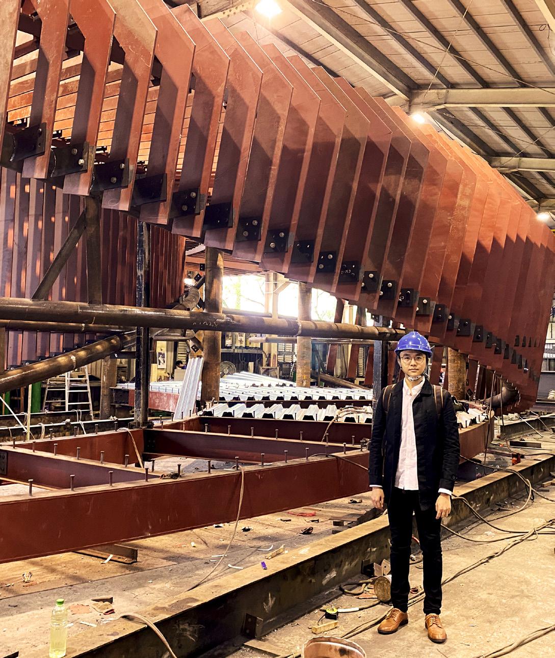
I wrote field report during site observation. I participated in mock-up testing and review in the CA phase.
LONG-CI COMMUNITY CENTER
PROFESSIONAL PROJECT
PROJECT INFORMATION
Architect: MHC Architects
Type: Institutional - Community (19,950 SF)
Location: Taoyuan, Taiwan
ROLE
Project Designer (Involved in SD, DD, CD)
RESPONSIBILITIES
• BIM Management
• Sustainable Strategies
• Permit Set
• Construction Drawings
• Consultation and Client Coordination
ROLE ON PROJECT
The design goal for the community center was to create a signature public space where citizens could exercise. I joined the project during the pre-design phase to manage the Revit model through to the CD phase. With only myself and a project architect unfamiliar with Revit on this project, I assumed responsibility for documentation and integrating design strategies using Revit. This BIM integration required coordinating with the structural engineer and curtainwall manufacturer to accurately detail the relationships between each sloping roof and curtain wall. To attain EEWH Silver certification, I proposed sustainable strategies focusing on energy efficiency and material selection. For instance, I utilized the roof to exhaust heat to improve climate control. Additionally, I contributed to design decisions and presented our progress in client meetings.
PROGRAMS USED
Revit, AutoCAD, Lumion


Conceptual renderings I created using Lumion.


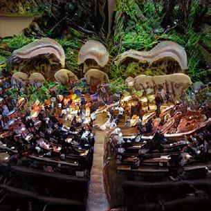
SHOPPING UNIVERSE
ACADEMIC PROJECT
PROJECT INFORMATION
Graduate Thesis Design, SCI-Arc, 2023
Type: Shopping Mall
Instructor: Elena Manferdini
Partner: Meng-Jung Ho
DESIGN CONCEPT
We investigated the intricate relationship between consumption and manufacturing, illuminated by globalization. The concealed transportation process behind consumption revealed that most consumers are unaware of a product’s entire lifecycle at the point of purchase. This consumption pattern led to an oversight of the pollution and waste generated throughout the complex manufacturing and transportation chain.
In light of the mall’s contribution to significant waste, we recognized the need to scrutinize the spectacle of consumerism. Hence, our shopping center design integrated three fundamental elements: the production space, the commercial space, and the third place. These areas were seamlessly blended with a pivotal concept: a community-based recycling system, fostering a dynamic and symbiotic environment.
By unveiling the lifecycle of products, our shopping mall design championed environmentally responsible building practices. It introduced a circular production chain that encouraged a symbiotic relationship between production and consumption, aiming for sustainability.
PROGRAMS USED
Rhinoceros, Grasshopper, AutoCAD, Unreal Engine

We generated the rendering in Unreal Engine to visualize the design concept.


Circulation
After people drop off their unwanted waste on-site, the waste is then sorted in the material recovery facility. Automated circulation redistributes the sorted waste to different reprocessing facilities over the roof. After reprocessing into ready-to-use materials, these raw materials are available for designers to use.


MYCELIUM
ACADEMIC PROJECT
PROJECT INFORMATION
Vertical Studio, SCI-Arc, 2022
Type: Biotech Research Center
Instructor: Elena Manferdini
Partner: Meng-Jung Ho
DESIGN CONCEPT
Climate change, health crises, scarcity or excess of resources, luxury and poverty, technology and inventions—all reinforced our understanding that humans are integral parts of a relational ecosystem, which includes other beings, biospheres, and environments. In our once globalized and hyper-connected world, we were increasingly exposed to complex phenomena and an expanded network of representation. To comprehend and address these challenges, we realized that managing large quantities and qualities of data was essential. Without data, we were unable to understand the world we lived in.
Our project engaged in a comprehensive building type while posing some foundational disciplinary questions: What was the form of contemporary participation in the construction of scientific knowledge? How could architecture provide a space where expanded agency could be effective? How could we design architecture that facilitated a network of stakeholders and allowed them to collaborate effectively? Could architecture promote awareness and active communication regarding technological investments? Specifically, could a BIOTECH facility act more like a parliament of negotiations, rather than just a lobby for a shared workplace?
PROGRAMS USED
Rhinoceros, Grasshopper, AutoCAD, Unreal Engine


We generated the rendering in Unreal Engine to visualize the design concept.


Design Approach: A.I. GAN Training


The concept of the project originated from A.I. GAN training. We trained a GAN using images of fungi and flowers that aligned with the specific scientific purposes of the building. The images of environments were produced by mistraining the GAN to create unexpected environments, or unexpected versions of expected environments.


Experimental Fungi Farm
Based on experimentation and the orientation of research, the labs aimed to provide a unique experience for preparing the emergent Martian exploration. Therefore, the labs were designed to be open, flexible, automated, connected, and collaborative spaces. The futuristic labs were also part of the creation and maintenance of fungi that cultivated and took care of different species


Cuboid Fractal
The geometric strategy of the facade was a cuboid fractal, where the surfaces constituted an ecological life. Mushrooms grew on the platforms and were collected by drones. The variation of color and metallic texture throughout the building reclaimed a bright characteristic as an essential identity for the labs, emphasizing the colorful and unique fungi.
FUZZY CONTUNITY
ACADEMIC PROJECT
PROJECT INFORMATION
Design Studio, SCI-Arc, 2021
Type: Elementary School
Instructor: Soomeen Hahm
Partner: Wei-Hung Chen
DESIGN CONCEPT
The core objective was to provide children with dynamic and inspiring places to explore and unleash their creativity. In this project, students were encouraged to take an active role in shaping their own educational experiences, defining the ways they played and the knowledge they acquired. By challenging elementary architectural principles, this initiative sought to break free from the structural norms that had governed the design of conventional buildings.
Through the incorporation of non-linear design processes and a deliberate embrace of fragmentation, this project manifested a captivating form of controlled chaos. This chaos gave rise to a sense of fuzzy continuity, encompassing two distinct meanings. Firstly, it abolished the specific boundaries separating interior classrooms from exterior playgrounds within the school premises. Secondly, continuity underscored the concept of sequential spaces, prioritizing the interconnectedness of different areas over their segregation. By interweaving indoor classrooms with outdoor playgrounds, this design allowed students to effortlessly transition between learning and play, seamlessly blending these activities into a cohesive and immersive experience.
PROGRAMS USED
Rhinoceros, Grasshopper, Cinema 4D, Octane


Design Approach: Furniture
This project began with furniture design that encouraged children to occupy the spaces with more freedom. The chairs were not meant to limit educational activities. Instead, the functions of the chairs were defined by the children themselves. The unlimited possibilities implied a sense of breaking the norm of traditional furniture. In other words, the chairs allowed students to occupy the classrooms with different postures, thereby stimulating more activities.

Blurred Boundary
As an extension of the furniture concept, the cluster of buildings was designed to maintain a continuous and fluid relationship between the surrounding landscape and the interior spaces. Blurred boundaries facilitated smooth transitions for various educational events within the learning environment.
Formations such as undulations, bifurcations, creases, inflections, aggregation, and fragmentation transformed the playground surfaces and exterior canopies into an architectural landscape. These elements guided and directed children through different levels of the interior spaces.


Continuous Circulation
This project defied conventional architectural principles, pioneering a transformative approach to educational spaces. It challenged the notion of compartmentalized environments, encouraging freedom and flexibility in student movement. The dynamic and harmonious design fostered organic exploration and empowered students to discover their passions

Learning Environment
By nurturing imagination, innovation, and collaboration, this visionary architectural endeavor aspired to create an educational setting that not only facilitated the acquisition of knowledge but also ignited a lifelong love for learning. It propelled young minds to surpass perceived limits and reach unprecedented heights of intellectual and creative achievement.
TRANSFIGURED OPUS
ACADEMIC PROJECT
PROJECT INFORMATION
Advanced Material and Tectonics, SCI-Arc, 2021
Instructor: Randy Jefferson, Dwayne Oyler
Partner: Freeland Livingston, Meng-Jung Ho, Wei-Hung Chen
DESIGN CONCEPT
Tectonics in architecture, blending the science and art of construction, is essential for understanding and shaping the design of complex building envelopes in contemporary architecture. Our project took a deep dive into the Opus by Zaha Hadid Architects, analyzing and documenting the sophisticated tectonics of its subsystems to uncover the nuances of structural and aesthetic design. This exploration provided the foundation for our reinterpretation of these tectonic elements within the Uppsala Concert and Congress Hall by Henning Larsen Architects, integrating technical expertise with an appreciation of the cultural dimensions of facade design.
Our approach expanded the scope of tectonics beyond mere construction techniques, encompassing materials, methods, sequences, and tolerances while embracing architectural expression through geometry and technique. This comprehensive perspective aimed to create a nuanced understanding of tectonics and highlight its role in both the functional and expressive realms of architectural design.
PROGRAMS USED

Rhinoceros, Grasshopper, AutoCAD


A view of the 3D chunk model to showcase how we blended the two projects together in terms of tectonics.


Pattern on the Elevation
The coated pattern consists of mirror-like dots of various diameters. The highly reflective strip pattern creates a pulsating e ect on the facade and provides the best performance in the hot climate.
Back-drained Cassette System
The skylight and so t areas are built with a back-drained cassette system with a carrier frame to enhance shape control and o er protection of the edges during handling.
MIXED-USE FOLLY
ACADEMIC PROJECT
PROJECT INFORMATION
Revit Folly, SCI-Arc, 2023
Type: Hotel
Instructor: Andrea Cadioli
Partner: Diba Ghazia, Jessie Ho, Wendy Chen
DESIGN CONCEPT
We explored Revit with Veras (an AI-powered visualization add-in for Revit) in this project. We embarked on a journey to envision a future where buildings coexist harmoniously with green spaces. The project encompasses four hotel levels, and we integrated eight sturdy columns into the design that serve a dual purpose, providing both functionality and enhancing the aesthetic appeal of the interiors. Additionally, our design incorporates multiple garden spaces within the tower, achieving a balance between solid and void spaces, fostering an environment where nature seamlessly blends with the built environment.
PROGRAMS USED
Revit, Enscape, Veras


SCORIA
ACADEMIC PROJECT
PROJECT INFORMATION
CATIA and Intelligent Digital Systems, SCI-Arc, 2023
Type: Shelter
Instructor: Kerenza Harris
Partner: Meng-Jung Ho
DESIGN CONCEPT
We investigated a specific design process that addresses the complexities of architectural forms and assemblies, with CATIA as the pivotal tool for design, optimization, and documentation in architecture projects.
This exploration included assessing new paradigms for architectural creation, emphasizing the shift from conventional design workflows to a novel methodology that harnesses technology innovatively to advance the field.
The project highlighted our advanced expertise in utilizing CATIA 3DEXPERIENCE, evidenced by our creation of parametric digital models employing Power Copies (PC), User Features (UF), and Knowledge Patterns (KP). Furthermore, we adeptly managed these parametric models, demonstrating a comprehensive grasp of their application in architectural practice.
Overall, our work illustrated the integral role of CATIA in the contemporary design and execution of architecture projects, showcasing its potential to enhance the architectural profession through technological integration.

PROGRAMS USED
CATIA


B-1. Color Variation 1


PC\THICK_U.Color = RU + “,” + GU + “,” + BU
PC\THICK_D.Color = RD + “,” + GD + “,” + BD
PC\THICK_BRIDGE.Color = RB + “,” + GB + “,” + BB
PC\THICK_U.Color = RHU + “,” + GHU + “,” + BHU

of the PowerCopy are defined, the PowerCopy unit can be instantiated on the surface according to the grid points. The height and color of each units change according to the distance between itself and the { F = InstantiateTemplate
F.SetAttributeObject(“Pt_Coord_0”, F.SetAttributeObject(“Pt_Coord_1”, F.SetAttributeObject(“Pt_Coord_2”, F.SetAttributeObject(“Pt_Coord_3”, F.SetAttributeObject(“Pt_Attractor”, EndModifyTemplate(F) i = i+1 }

InstantiateTemplate (“RT_UNIT”, Result)


F.SetAttributeObject(“Pt_Coord_0”, oList0.GetItem(i))
F.SetAttributeObject(“Pt_Coord_1”, oList1.GetItem(i))
F.SetAttributeObject(“Pt_Coord_2”, oList2.GetItem(i))
F.SetAttributeObject(“Pt_Coord_3”, oList3.GetItem(i))
F.SetAttributeObject(“Pt_Attractor”, Input\Pt_Attractor)
EndModifyTemplate(F)


TECTONICS OF FLUIDITY
ACADEMIC PROJECT
PROJECT INFORMATION
Undergraduate Thesis Design, Tamkang University, 2017
Type: Temple
Instructor: Ying-Chang Yu
Partner: Individual Work
DESIGN CONCEPT
In my research, I delved into fluidity—a concept reflecting the universe’s inherent state of constant change—as it manifests in mechanics, substances, and spaces like water, landscapes, and organic structures. This fluidity is also evident in architecture, transitioning from medieval arches and domes to contemporary free-form designs with concrete shells and curved cladding. Despite its aesthetic appeal, free-form architecture presents significant challenges, particularly in fabricating double curvature panels, which impact cost and quality.
Recognizing these challenges, I focused on developing an accurate and efficient method for manufacturing double curvature façades from flat pieces of materials, given their increasing significance in contemporary architecture with the rise of computational design. My work closely intertwined architecture and tectonics, analyzing them through the prism of fluidity and investigating the relationship between materials and geometry from an aesthetic standpoint. I provided detailed insights into the practicalities of producing double curvature panels, supported by a collection of detailed drawings and parameterized construction systems.
PROGRAMS USED
Rhinoceros, Grasshopper, AutoCAD, V-Ray


Design Approach: Kerf Bending and Form-resistant Structure
Most of the industrialized materials are linear and planar for the purpose of standardization and efficiency. Therefore, the first challenge in this design is transforming planar materials into double curvature units. The idea involves kerf bending, which is the process of removing thin sections from the flat panel that makes the panel loses ots rigidness and becomes flexible.
The unit is designed to be form-resistant structure to maintain free-form shape. A pair of kerf bent MDF panels are connected by bolts and casings.


Materiality
Materials other than MDF are also experimented in this phase.
A - B Aluminum
C - D Acrylic: The sub-structure increase the rigidity.
E - F Concrete: The MDF panels are the formwork of the posttensioned concrete system, and the bolts and casings serve as reinforcement.


Concept
The concept of fluidity is based on the previous research on double curvature panel manufacture. The integral morphological development of space is derive from the fluid phenomenon Forming mechanics of five fluid phenomena are analyzed and reinterpreted along with the spatial development.
Form-finding
Fluid phenomena are redefined and applied to form-finding. Given the initial points and direction, the form develops under the consideration of attraction and repulsion among particles. The centers of the obstacle are redefined as open spaces; some of the turbulent areas become semi-exterior spaces. In addition, the trials of fluid motion assimilate into the landscape.


