
Volume 11. No.1, January 2023
International Journal of Emerging Trends in Engineering Research
Available Online at http://www.warse.org/IJETER/static/pdf/file/ijeter011112023.pdf https://doi.org/10.30534/ijeter/2023/011112023

Design and Comparison of Vehicle Mounted Wind Turbines
Halima Begum1 , Md. Arafat Hossain2
1East West University, Bangladesh, hab@ewubd.edu
2 East West University, Bangladesh, 2017-2-80-032@std.ewubd.edu
Received Date: December 5, 2022
ABSTRACT
Accepted Date: December 27, 2022 Published Date : January 07, 2023
the run, which will help in providing better mileage, lower charging time.
Electric vehicles (EVs) are gradually taking place of the conventional fossil fuel-based vehicles. However, popularity of EVs is hindered due to longer charging time and lower mileage. To address the mileage issue, in this paper we have proposed to use wind turbines to be mounted on vehicle, so that it can harness the wind energy to charge the batteries while the vehicle is in motion. We have designed two types of wind turbines: horizontal axis and vertical axis turbines and our analysis showed that vertical axis turbines provide better solution in extracting maximum wind power.
Key words: Vehicle mounted wind turbine, horizontal axis turbine, vertical axis turbine, diffuser, beak
1. INTRODUCTION
According to the U.S. Energy Information and Administration, gasoline consumption by transportation sector has increased despite the improvement of overall fuel economy in cars and light trucks. In the year 2021, petroleum products accounted for about 90% of the total U.S. transportation sector energy use [1]. Due to rapid depletion of the non-renewable fuel sources, price hike of the gasoline as well as their harmful impact in the environment, people are now willing to use hybrid electric (HEV) or fully electric vehicles (EV), provided these offer cheaper, and user-friendly alternatives.
For EVs, batteries are the main power source to run the electric motors. These batteries need to be recharged regularly, and at present the main source of this power is grid electricity. As a result, there will be an increase of pressure on the grid electricity if EVs replace the conventional fuel-based vehicles. Moreover, the time for recharging completely an EV can be as little as 30 minutes to more than 12 hours [2]. A typical electric car battery (60 kWh) takes about 8 hours to charge from empty to full, with a 7 kW charging point [2]. This timing issue is not user friendly. The researchers are thinking of using renewable sources such as solar or wind power as alternatives to charge the batteries of EVs, while on
In this paper we have proposed to introduce wind turbines on an EV, connected with a suitable generator to generate electricity utilizing the wind flow/power it experiences during the vehicle movement. Efficient designand implementation of wind turbines are crucial on the vehicles to obtain maximum energy output. In this paper, we have designed two types of wind turbines: Horizontal Axis Wind Turbine (HWAT) and Vertical Axis Wind Turbine (VAWT) and analyzed their performance to obtain better energy output.
2. LITERATURE REVIEW
A few numbers of wind powered vehicles were designed and constructed so far. For example, in the year 2008, a team of students from the University of Stuttgart in Germany created Ventomobile, the first vehicle run solely by a two-meter twin blade wind turbine [3]. On the other hand, a formerly V6333bhp internal combustion Lotus Exige was re-engineered to build the customized sports-car Lotus Nemesis to run solely by External Wind Turbines (EWT) [3]. Apart from these, severalresearch havebeenconducted tothedesignofthe wind turbines to be used in vehicles to maximize power output.
Chen, T. Y. et. al. [4], developed a shrouded, small, horizontal-axis wind turbine for moving vehicles. They investigated how the flanged type diffusers affect the performance of rotor of small wind turbines. They worked on different rotor solidities (20–60%) and wind speeds (10–20 m/s). They found that use of flanged diffuser can significantly increase the output power output, torque, and rotational speed of the wind turbine, which also largely depends on rotor solidity and wind speed. In their research, they found that rotors of 30% and 40% solidity can generate the largest power and torque outputs, compared to the rotor of 60% solidity.
M. Awal, M. Jusoh et. al. [5] have designed a Horizontal Axis Wind Turbine (HAWT) for vehicles. In addition to the portability, practical shape and light weighted characteristics, their designed HAWT has high rpm and torque compared to other conventional WTs. Through experiment theyfound that, their designed turbine can harvest enough wind energy to
Halima Begum et al., International Journal of Emerging Trends in Engineering Research, 11(1), January 2023, 1 – 7 1
ISSN 2347 - 3983
Figure 1: Exploded view of assembly of Horizontal Axis Wind Turbine (HAWT)
generate up to 200 W of electricity, if the vehicle's speed is about 80 km/hr.
Abishek et al. [6] modeled two ducts of a varying crosssection with a fan connected with an alternator. Through simulations they have showed that the speed at the end of the duct was in the range of 121–147 m/s. They have also modified the alternator to obtain high voltage AC output to power up the batteries of the cars, which contributed in 23% increase in the comprehensive range of EV.
P. W. Ripley [7] designed a system for harnessing wind energy to charge the battery of an electric motor vehicle. His invented system is capable of charging the vehicle's battery while it is parked or in motion. A roof-mounted, internal wind turbine is used to harness wind power, while the vehicle is in motion. On the other hand, when the vehicle is parked, an external wind turbine attaches to the internal wind turbine, which is designed to catch the ambient wind current.
3. DESIGN OF WIND TURBINE
There are 2 types of wind turbine based on the position of the rotor axis of revolution: Horizontal Axis Wind Turbine (HAWT) and Vertical Axis Wind Turbine (VAWT). In this paper we have designed both types of turbines using SOLIDWORKS, and then analyzed their performance on harnessing energy from the wind flow during the vehicle movement.
3.1 Design model of Horizontal Axis Wind Turbine (HAWT)
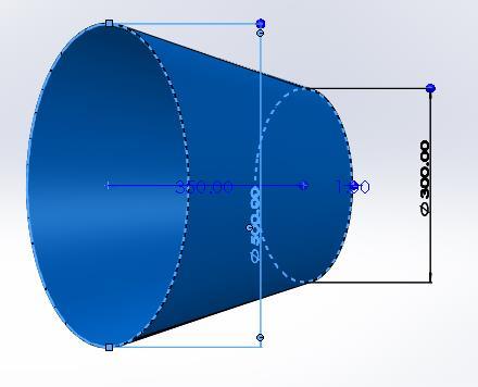
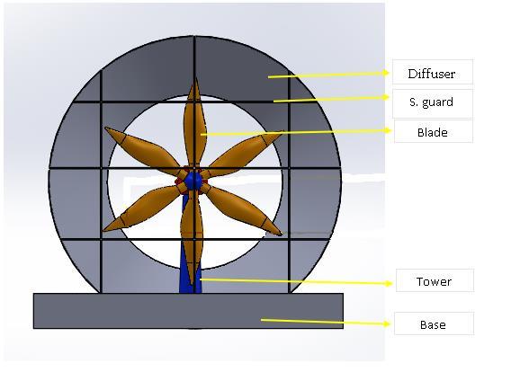
In our designed model of HAWT, the major components that made up our Horizontal Axis Wind Turbine (HAWT) are shown in Figure 1. These include, the base, the tower, turbine blades with hub i.e., the rotor and the diffuser (cage). We have included a cone-shaped diffuser as shown in Figure 2 with the purpose of increasing the velocity of the air as it travels
through the turbine.
The turbine blades are attached with the hub, which is then connected to the generator through the main shaft. In our designed model, we are using 6 blades, therefore, we have designed the rotor hub as shown in Figure 3, so that it can incorporate six blades. The six bladed plan is chosen so that internal blades can provide a low start up speed, and when the wind flow rate gets excessively high, provides braking function
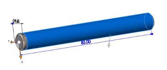
The main shaft is a piece of metal in the form of a tube (a cylinder) and is responsible for conveying the energy fromthe wind turbine blades to the other parts of the wind turbine.
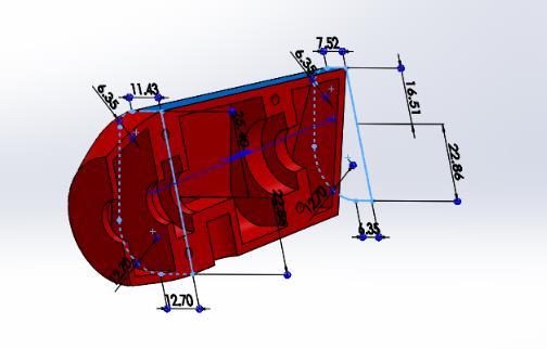
Figure 2: Design of the diffuser (cage) for HAWT (All dimensions are in mm)
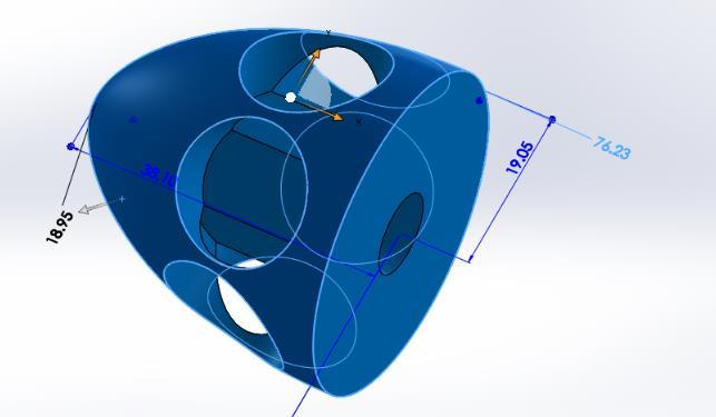
Figure 3: Designed HAWT rotor for sixblades (All in mm)
Figure 4: The main shaft and bearing (All dimensions are in mm)
Halima Begum et al., International Journal of Emerging Trends in Engineering Research, 11(1), January 2023, 1 – 7 2
Figure 5: The main bearing (All dimensions are in mm)

Figure 8: Outer view of the designed generator body(housing)
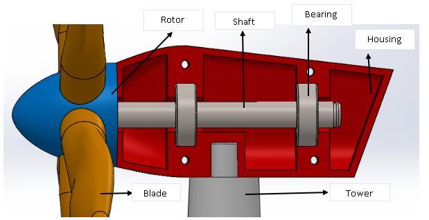
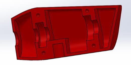
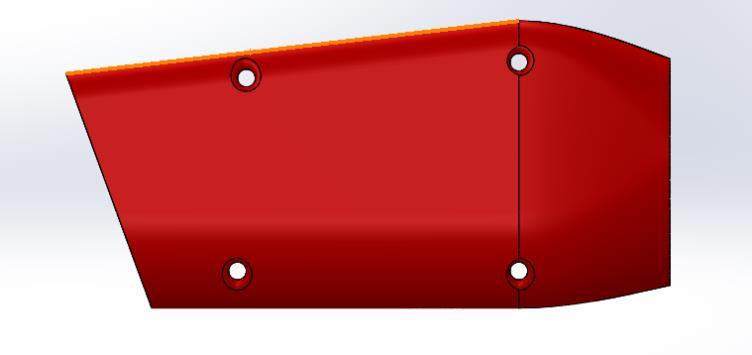
Figure 6: Inside portions measurement of the designed housing (Dimensions are in mm)
Figure 9: The tower of wind turbine (All dimensions are in mm)
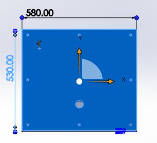
Figure 7: Inside view of the designed generator body(housing)
Therefore, it is exposed to its own weight, the load of the rotor (blades and hub), and weights applied by different parts. The main shaft is 85 mm long and the diameter is 9.65 mm as shown in Figure 4. With the help of the main bearing, it transmits the rotational energy of the rotor to the generator.
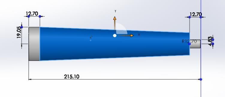
The dimension of the main shaft is shown in Figure 4. The main shaft has to bear gravitational load, aerodynamic loads fromthe rotor, as well as reactions fromthe mainbearings and the generator shaft. The threaded end of the main shaft helps to couple the mainbearingonto the shaft duringthe assembly. SAE 1006 HR (carbon steel) is selected for the shaft design [8].
Figure 10: Inside construction view of the designed housing body after assembly
Figure 11: Design of the Base for HAWT (All dimensions are in mm)
al., International Journal of Emerging Trends in Engineering
11(1), January 2023, 1 – 7 3
Halima
Begum et
Research,
Figure 12: The outlet safety guards of wind turbine (All dimensions are in mm)
Figure 15: Designed blade profile part A (All dimensions are in mm)
Figure 13: The inlet safety guards of wind turbine (All dimensions are in mm)
Figure 16: Designed blade profile part B (All dimensions are in mm)
we have kept the height as 215.10 mm. After the assembly of different parts, we got the final design of the HAWT as shown in Figure 10
The tower, turbine, main shaft, generator all will be set inside the diffuser. The diffuser is then set with a base which is displayed in Figure 11. To prevent bird’s death and rotor comingout fromthe diffuser (cage) in case it breaks down, we are using inlet and outlet safety guards for the wind turbine which are shown in Figure 12 and Figure 13. They are made of aluminums.
Figure 14: Designed blade profile (Designed in SOLID WORKS)
As main bearings, either triple row roller bearings or doublerow tapered roller bearings are the options [8]. However, we would prefer the tapered roller bearing because of its optimal rolling behavior and its self-aligning characteristics. AISI 52100 steel is very hard and can withstand wear, therefore, we recommend using this material for the bearing [8].
A housing space for placing the turbine hub, main shaft, the bearings has been designed with the dimensions shown in Figure 6, Figure 7, and Figure 8.The tower ofthe wind turbine carries the load of the rotor, the shaft and the generator. The tower is made of steel, and in our design as shown in Figure 9
In a HAWT, the rotor sharp edges are mounted inside the diffuser, which is then positioned on the highest point of the tower. As theairflows throughthediffuserandpassesthrough the safety guard section, a variation in the direction of the air vortex is created. Due to these vortices, the air velocity is slightly bent and hit the blade body; then it exits at a good speed by giving pressure at the rear and the body parts of the diffuser, while this process occurs in a periodic manner.
The design of the blades used in this project is based on blade element theory and the Betz limit, which states that the theoretical maximum energy efficiency of any wind turbine is 0.59, i.e., not more than59% ofthe energycarried bythe wind can be extracted by a wind turbine [9].
Halima Begum et al., International Journal of Emerging Trends in Engineering Research, 11(1), January 2023, 1 – 7 4
Figure 17: Designed blade profile part C (All dimensions are in mm)
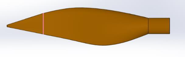
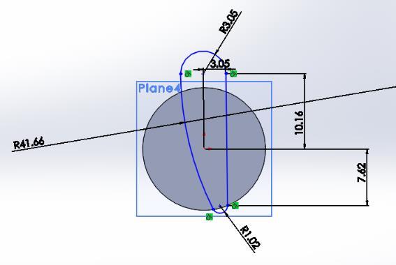
Figure 18: A modified version of the designed blade
The blade incorporates an overall blade twist of 75° from root to tip. The majority of the blade twist, around 26°, occurs in the first 132.40mm of blade from the root and then turns into a gradual twist over the remaining 160.50mm of the blade which is shown in Figure 14, Figure15, Figure 16, Figure 17, and Figure 18. This aerodynamic shape helps it to face a lot of air pressure on its twisted mode.
Research conducted by Phillips et. al. [10] reveals that if the Exit area ratio (EAR) of a diffuser(cage) is kept as 2.22 and the length to diameter ratio is kept as 0.35, then there is an augmentation of shaft power coefficient by 1.8. By using inlet area of the diffuser ���� and exit area of diffuser ����, we can calculate the EAR value, moreover the outlet/exit diameter of the diffuser ���� values by following equations [8], [10]
Figure 19: Exploded view of assembly of Vertical Axis Wind Turbine (VAWT)
=√4��
Ifthe massflowrateofwindis �� anditflows withwindspeed �� inthe axial directionofthe wind turbine, thenit posses some kinetic energy, K.E which is shown in (5). The air mass flow rate, m is dependent on the swept area of the rotor, ����, the density of air, ����, and wind velocity as represented by (6). Therefore, kinetic energy of air is obtained as in (7) [11], which is also considered as the available wind power, ���� �� �� =1/2����2 ( 5 ) �� =���������� ( 6 ) ��.�� =1/2����������3 ( 7 )
The available wind power ���� is the most significant output for us and in the result section we demonstrate this power along with different wind speed due to the vehicle movement.
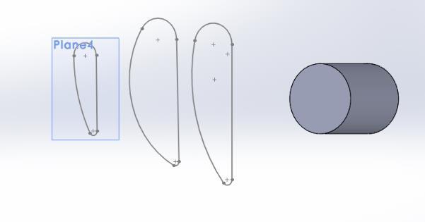
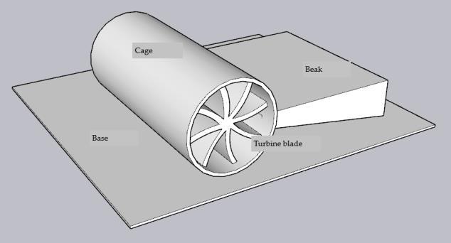
3.2 Design model of Vertical Axis Wind Turbine (VAWT)
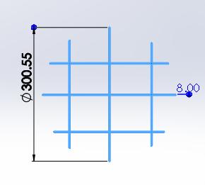
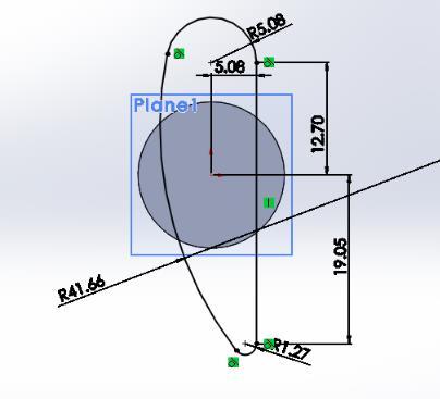
We have designed a vertical axis wind turbine (VAWT) containing 4 main parts: the cage, the beak, the base and the turbine blades. Figure 19 shows the exploded view of the assembly of the designed VAWT. Here the beak is designed in such a waythat it can reduce the drag force and increase the velocity of the air that hits the turbine blades. It is like an air scoop and the frame is of the shape of a whistle
There are 8 blades in our designed turbine, which are connected to the shaft, twisted along with 45degrees each and can cover the 360 degree of turbine blade area, as shown in Figure 20. This structure is adjusted with two componentsbearing stand which is fixed to the base, and pulley, which is fixed with the generator.
Figure 20: Designed turbine blade for VAWT

Halima Begum et al., International Journal of Emerging Trends in Engineering Research, 11(1), January 2023, 1 – 7 5
������ = ���� ����
���� = ������ 2 4
2
��
= ����
4
��
( 1 )
(
)
��
�� 2
( 3 )
��
�� ��
( 4 )
Our planned broad enclosure is associated at the center of the base, and it covers the fan. The generator is put over its rectangular base and associated by screws with the base. Additionally, it has a pulleyassociated with the pivoting shaft.
The last part is the beak. The use of beak will help to harvest maximumamount ofair bypushingit to the outlet of the beak, which in turn helps to give the highest impact force on the fan blades. At the end of the beak, we bent it at 45° degrees of angle for each fan blades. 45° degree*8 blades would cover up 360° degrees and for the wake rotation, all the blades will get more rotational power, and can generate good amount of energy.
According to The Betz Limit the maximum 59.26% of power can be harvested from the wind [9]. If the wind mass flow rate is ��, the density is ����, and it flows with speed �� in the axial direction of the wind turbine, then the available wind power ���� is obtained according to (8) ���� =1/2����������3 ( 8 )
In the beak (nose), the outlet velocity ���� and the inlet velocity of air ����, are different. The velocity of air at the outlet, ���� is the main responsible one to provide energy to move the blades, or in other words, the rotor shaft. That means, �� in (8) is equal to ����. The outlet velocity of the beak, ���� is obtained as, �� =���� =���� ×√�������� ( 9 ) Here, �� =1.4, the specific gas constant for dry air, �� =287 J Kg-1k-1 , ���� is the static temperature at the outlet and ���� is the Mach number at the outlet. ����is calculated using (10) and ���� is calculated using (11)
. ���� =�� (����)2 2���� ( 13 )
In (8), ���� is considered as outlet area of the beak, i.e., ����. The ���� in (8) is the density of air at the outlet. It is obtained using the following equation.
������������ =������������ ( 14 )
where, density of air at the inlet, ���� is obtained as ���� =����/������ ( 15 )
Here, ���� is the static inlet air pressure in pascal and it is calculated from (16).
��= ���� +0.5× ���� ������ ×(����)2 ( 16 )
The �� in (16) is the average air pressure at sea level which is equal to 101320 Pascal.
4. PERFORMANCE ANALYSIS
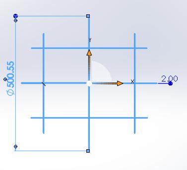
For HAWT, considering the inlet diameter of the diffuser ���� as 500mm, the Area ���� is calculated as ���� =��×052/4= 019635 m2 . Considering ������ =222, and using (1), the exit area of the diffuser is ���� =������×���� =2.22×0.19635 = 0435897 m2 . Therefore, the outlet diameter of the diffuser is obtained as ���� =√((4×0435897)/31416) =075 m.
With a rotor diameter of 0.46 ��, the swept area ���� is obtained as ���� =(3.1416× 0.462 )/4=0.167 m2. For the case whenthe wind speed is �� =2222 m/s, i.e., 80 km/hr, and the density of air is ���� =1.225 kg/m2, the wind power is calculated as ���� = 1/2×���� ×���� ×��3 =1/2× 0167× 1.225×22.223 =1122.16 watts
For different wind velocities the extracted wind power by our designed HAWT varies and it is shown in Table 1.
Table 1: Extracted wind power by the HAWT for different wind velocities
In these equations, ���� and ���� are area of the inlet and outlet of the designed beak. �� is the stagnation temperature of the air and ���� is the Mach number at the input and it is calculated using (12), where ���� is the static temperature of the air at the inlet. ���� = ���� √�������� ( 12 ) ���� is obtained using the following equation, where ���� is the specific heat capacity of the air and it is equal to 1005 J Kg-
Wind velocity (Km/hr)
50 60 80 100 120 Inlet wind velocity (m/s)
13.88 16.67 22.22 27.78 33.33 Wind power (watts)
273.52 473.84 1122.16 1209.16 3787.28
We can see that extracted power increases with the increase of wind velocity.
Halima Begum et al., International Journal of Emerging Trends in Engineering Research, 11(1), January 2023, 1 – 7 6
���� ���� = ���� ���� ×[1+�� 1 2 (����)2] ��+1 2(�� 1) [1+�� 1 2 (����)2] ��+1 2(�� 1) ( 10 ) �� ���� =[1+�� 1 2 × (����)2] ( 11 )
1
-1
K
Figure 21: Comparison of extracted wind power by HAWT and VAWT for different wind velocities
For VAWT, the design of the beak influenced the outlet wind velocity, hence the extracted wind power. Considering stagnation temperature of the air, 20∘ C, i.e., �� =293 K, the inlet area of the designed beak as ���� =0062 m2 and the outlet area of the designed beak as ���� =0026 m2, the calculated outlet wind velocities and wind power for different wind velocities are shown in Table 2. It can be observed that outlet wind velocity is significantly larger than the inlet wind velocity, therebyavailable wind power for the turbine is more.
Table 2: Extracted wind power by the VAWT for different wind velocities

Wind velocity (Km/hr)
50 60 80 100 120
above another. In this paper the effect of the drag force experienced by the turbine blades has not been considered, and we plan to include it in the estimation of the shaft power generation in future.
REFERENCES
1 U.S. Energy Information Administration-EIA- Independent Statistics and Analysis, Use of energy explained-Energy use for transportation, https://www.eia.gov/energyexplained/ use-of-energy/transportation-in-depth.php, November 11, 2022.
2 How Long Does It Take to Charge an Electric Car? Pod Point, https://pod-point.com/guides/driver/how-long-tocharge-an-electric-car (accessed Apr. 07, 2021).
3. Burdett, Richard. Wind Powered Cars: A Possibility or Crackpot Philosophy?, The Renewable Energy Hub, www.renewableenergyhub.co.uk/blog/wind-powered-cars-apossibility-or-crackpot-philosophy/ (accessed Apr. 07, 2021).
4. Chen, T. Y., Y. T. Liao, and C. C. Cheng. Development of small wind turbines for moving vehicles: Effects of flanged diffusers on rotor performance, Experimental Thermal and Fluid Science Vol. 42 pp. 136-142, 2012.
5. Awal, Md Rabiul, Muzammil Jusoh, Md Nazmus Sakib, Fakir Sharif Hossain, Mohd Rashidi Che Beson, and Syed Alwee Aljunid. Design and implementation of vehicle mounted wind turbine, ARPN J Eng Appl Sci Vol. 10, pp. 8699-8860, 2015.
6 Gupta, Abhishek, and Naveen Kumar. Energy regeneration in electric vehicles with wind turbine and modified alternator, Materials Today: Proceedings Vol. 47, pp. 3380-3386, 2021.
Inlet wind velocity (m/s)
13.88 16.67 22.22 27.78 33.33 Outlet wind velocity (m/s)
38.04 40.09 54.07 67.33 81.88 Wind power (watts)
751.37 1000.97 2418.74 4690.15 7764.36
Figure 21 shows the extracted wind power by HAWT and VAWT for different wind velocities. It can be observed that the extracted wind power for the same wind velocityis greater for the designed VAWT compared to that of the HAWT.
5. CONCLUSION
In this paper we have designed both horizontal axis and vertical axis wind turbines. We have then analyzed the extracted wind power by these turbines and found that in both cases with the increase of vehicle's speed, the extracted wind power increases. However, for the same speed of the vehicle, the extracted wind power by the VAWT has been always found to be greater than that of the HAWT. In addition to this, if space constraint on the vehicle's roof is considered, then VAWT will be a better choice since they can be stacked one
7 Ripley, Peter W. Wind turbine for electric car, U.S. Patent 8,513,828, issued August 20, 2013.
8 Quartey, Gideon, and Stephen Kwasi Adzimah. Generation of electrical power by a wind turbine for charging moving electric cars, J. Energy Technol. Policy Vol. 4, pp. 19-29, 2014
9. Thӧnnißen, Frederik, Markus Marnett, B. Roidl, and WolfgangSchrӧder. AnumericalanalysistoevaluateBetz’s Law for vertical axis wind turbines, Journal of Physics: Conference Series, Vol. 753, no. 2, pp 022056. IOP Publishing, 2016.
10 Phillips, Derek Grant. An investigation on diffuser augmented wind turbine design, PhD dissertation, Dept. of Mech. Eng., University of Auckland, 2003.
11. Johnson, Gary L. Wind turbine power, Wind turbine power, energy and torque (2005).
Halima Begum et al., International Journal of Emerging Trends in Engineering Research, 11(1), January 2023, 1 – 7 7