4 minute read
3D Imaging Sensor vs. Traditional LIDAR/Camera Combinations

from True View 515 FAQ
by WebsiteWise

1. What is a 3D imaging Sensor (3DIS)?
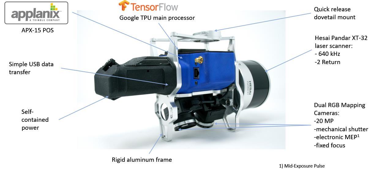
A 3D Imaging Sensor (3DIS) is a definition coined by us (GeoCue Group Inc.) Basically, it is a system of hardware and software that can generate a true 3D colorized point cloud.
Advertisement
A general 3DIS derives geometric information (X, Y, Z, time) and some target characteristic information (infrared reflectance, for example) from a laser scanner (or radar) and radiometric information from calibrated, synchronized photogrammetric cameras. The laser (or radar) points are “painted” from the synchronized images using a 7 degree of freedom (7 DOF – X, Y, Z, Pitch, Yaw, Roll, Time) ray tracing algorithm.
The camera(s) must be synchronized to the Position and Orientation System POS) such that the full orientation for each image frame can be computed. This means the system must be encoding time-synchronized camera pitch, yaw and roll in addition to the X, Y, Z location of the camera focal point. These data tuples are called the full, time synchronized Exterior Orientation (EO) of the camera.
Post-processing software must include ray tracing algorithms that trace each 3D LIDAR (or radar) point back to the appropriate source image (not a derived image such as an orthophoto). This process requires both the aforementioned camera EO as well as precise camera calibration.
2. What is the advantage of the 3D Imaging Sensor compared to a standard LIDAR system?
Data from a standard LIDAR system can be used to generate a 3D monochromatic point cloud. Attributes of the point cloud typically include: • X, Y, Z position in an exploitation spatial reference system (SRS) • High resolution GPS time of pulse • Intensity of the laser return • Return number (if your LIDAR is multiple return capable) • Scan angle (angle of the beam relative to nadir when this point was detected) • Flight line (swath) ID
Note that no color (or, in general, radiometric) information is contained in the above information. A 3D imaging sensor (3DIS) includes both a laser scanner and one or more
GeoCue Group, Inc. 9668 Madison Blvd., Suite 202 Madison, AL 35758 Page 5 of 29 256-461-8289 (voice) 256-461-8249 (FAX) www.geocue.com
synchronized photogrammetric cameras (the True View 515 includes two Red-GreenBlue photogrammetric cameras). The system is designed to achieve a coincident field of view (FOV) from all sensors. Post-processing software colorizes the points from the camera imagery to add, in the case of the True View 515, Red-Green-Blue (RGB) values for each LIDAR point. Note that the camera system in a 3DIS is not restricted to RGB cameras.
3. Is a LIDAR with a third-party add-on camera (such as a Sony Alpha 7) essentially a 3D imaging Sensor (3DIS)?
It can be, but most are not. The camera must be synchronized to the Position and Orientation System such that the full orientation for each image frame can be computed. This means the system must be encoding time-synchronized camera pitch, yaw and roll in addition to the X, Y, Z location of the camera focal point. This is called the full, time synchronized Exterior Orientation (EO) of the camera.
Post-processing software must include ray tracing algorithms that trace each 3D LIDAR point back to the appropriate source image. This process requires both the aforementioned camera EO as well as precise camera calibration (precise camera calibration is referred to as camera Interior or Intrinsic Orientation, IO).
Many “strap-on” LIDAR/Camera systems expect you to process the imagery to an orthophoto mosaic using a software package such as Pix4D or Metashape. A second software tool such as Global Mapper is then used to interpolate a color for each LIDAR point using this orthophoto. as the colorization source. This is not a true 3DIS data set since the imagery and hence the point colorization is 2D.
4. What is the data quality difference between a True View 515 3DIS and a LIDAR with a “strap-on” camera?
Most strap-on systems do not have the full hardware support to derive synchronized Exterior Orientation of the camera(s) from the POS. In addition, they typically have you colorize point clouds from an orthophoto created from the camera images. The result is 2D rather than 3D colorization of the point cloud. This happens because an orthophoto cannot represent more than one elevation point for each X, Y position.
If a tree limb hangs over a road, a 3DIS will have correct colorization for a road point as well as a tree point (or points, for that matter) directly above the road point (that is, points that share the same X, Y coordinates but have differing Z coordinates). Obviously since images are 2D, the 3DIS algorithm must extract these colorization pixels from different source images.
GeoCue Group, Inc. 9668 Madison Blvd., Suite 202 Madison, AL 35758 Page 6 of 29 256-461-8289 (voice) 256-461-8249 (FAX) www.geocue.com