


The Siemens SIMATIC S7-1200 G2, supplied by APS Industrial, is designed to meet the evolving demands of industry and machine building. With enhanced performance, seamless scalability and advanced motion control capabilities, it delivers efficiency for cost-effective automation solutions.
The second-generation controller features a compact design with a 25% reduced DIN rail footprint, making it suitable for space-constrained applications. Equipped with fail-safe integration, it can provide robust safety for critical operations, while its advanced communication capabilities, including NFC functionality, enable wireless diagnostics and IT/OT integration.
The S7-1200 G2 is designed to provide high flexibility, offering easy integration with the Siemens TIA Portal for unified engineering across automation components. Its efficient motion control supports single-axis, multi-axis and kinematic operations, catering to diverse industrial requirements. Memory and processing power enhancements ensure it can handle more complex tasks with ease, supporting up to 31 Profinet devices with IRT for high-speed, synchronised communication.
Whether for standalone or interconnected systems, the SIMATIC S7-1200 G2 is engineered to optimise productivity, reduce complexity and futureproof operations. Partner with APS Industrial to discover how this game-changing controller can drive efficiency in your automation projects.


Industrial automation continues to evolve rapidly, with AI now becoming available to play a critical role in maintaining competitiveness across multiple industries. No longer an optional enhancement, AI-driven automation is becoming a necessity as companies strive to optimise efficiency, reduce downtime and enhance decision-making. This is particularly so in the area of predictive and prognostic maintenance capabilities.
At the same time, whether it be for the purposes of AI data gathering or other more traditional business use, the growing adoption of cyber-physical systems is introducing new challenges in cybersecurity. As industrial networks become more interconnected, managing cyber risk is becoming increasingly complex. The rise of industrial IoT, cloudbased automation and remote monitoring expands attack surfaces, making proactive cybersecurity measures essential. Companies must develop robust strategies to protect critical infrastructure, safeguard data and ensure system integrity against evolving cyber threats.
Meanwhile, in the water and wastewater industries, the choice between ultrasonic and radar level measurement technologies remains a key consideration. Both technologies offer advantages, but selecting the right one depends on environmental conditions, accuracy requirements and budget constraints. Understanding the strengths and limitations of each technology is crucial for optimising process control and ensuring reliability in water and wastewater operations.
In this issue we also have a tech tips article on avoiding the software gotchas that can happen when making choices around IO-Link network devices.
As always, more detailed daily news and new automation products can be found on processonline.com.au and by subscribing to our twice-weekly email newsletter.
Glenn Johnson Editor pt@wfmedia.com.au


The federal government has awarded the University of Newcastle $20.7 million in funding to develop a ‘Future Industries Facility’ at the university’s Callaghan Campus.
The university says the Future Industries Facility will bring together undergraduate students, SMEs and community from across the Hunter to test and scale-up new technology and upskill people in Australia’s energy, resources and manufacturing sectors, for the net zero economy.
University of Newcastle Vice-Chancellor Professor Alex Zelinsky said the Future Industries Facility was the next step in the region’s transformation.
“This crucial new initiative will enable us to boost regional development, and develop nationally significant technology to help us achieve net zero and create jobs in our region,” he said.
The ISA has announced the publication of ANSI/ISA-62443-2-1-2024, Security for Industrial Automation and Control Systems, the latest update to the ISA/IEC 62443 series of standards.
Addressing cybersecurity on an organisation-wide basis can be a daunting challenge for companies that rely on industrial automation and control systems in their operations. The ISA says that while no one-size-fits-all set of security practices can meet the widely varying security needs across global industry, ANSI/ISA-62443-21-2024 addresses the complexity by setting forth requirements for establishing, implementing, maintaining and continually improving a security program intended to reduce IACS security risks to tolerable levels.
“Security is a balance of risk versus cost, and each situation will be different,” said ISA99 Co-Chair Eric Cosman of OIT Concepts. “In some, the risk can be related to health, safety and environmental factors rather than purely economic impact. Thus, a predetermined set of mandatory security practices could be overly restrictive and costly — or else insufficient to address the risk. This newly updated standard provides the flexibility to reach the right level of risk versus cost for a given operation.”


SICK and Endress+Hauser have announced that their strategic partnership — first announced in October 2023 and signed in August last year — has completed its main task of integrating SICK’s gas analysis and flow measurement technology into Endress+Hauser’s instrumentation portfolio.
The production and further development of the gas analysers and flowmeters were brought together under the umbrella of Endress+Hauser SICK GmbH+Co. KG. SICK and Endress+Hauser will each hold 50% of the joint venture as of 1 March 2025.
“This partnership is a perfect match,” said Dr Peter Selders, CEO of the Endress+Hauser Group. “It creates new opportunities for growth and development, particularly in the sustainable transformation of the process industry. By joining forces, we offer added value to our customers. Our combined efforts will make us faster and ultimately more successful than if we acted alone. In this case, one and one equals more than two."

James H. Chappell*
The use of artificial intelligence is no longer an option in many industries, but often a requirement to keep up with the competition.
State-of-the-art artificial intelligence technologies improve industrial processes, proactively detect and solve problems, and provide guidance for risk-based decisions. In doing so, they provide companies with significant cost savings and improved competitiveness.
Over the past 20 years, AI has significantly transformed the industrial workplace. Industry is deploying AI on-premises, in the cloud, at the edge, and through many types of hybrid architectures.
AI itself is not one thing but comprises a number of technologies, including neural networks, deep learning (a type of neural network), natural language processing, computer vision, unsupervised machine learning, supervised machine learning, reinforcement learning, transfer learning and others. Industry applies these types of AI in a variety of ways to create targeted solutions.
We can categorise industrial AI analytics into three different types — the three Ps of industrial AI:
1. Predictive: Predictive AI predicts when subtle changes in performance indicate bigger problems in the future. It detects incipient problems and inefficiencies, as well as errors in the design process, by analysing industrial ‘big data’ from sensors, data lakes, data historians, calculated values, audio, video, and other sources.
2. Prescriptive: Once predictive and performance analytics identify issues, prescriptive analytics provide root-cause analysis, planning and decision support, and courses of action that are most probable to remedy and optimise a situation.
3. Prognostic: This type of AI uses neural nets, deep learning, and reinforcement learning technologies to forecast future events. Industries use it to optimise monitoring, control and scheduling and to help determine how long an anomalous asset or process can continue to safely operate before it fails or loses significant function.
The first of these three Ps — predictive AI — is one of the more common advanced technologies used in industry today. Although referred to as ‘predictive’, it is actually a very effective method of anomaly detection in near real time. It uses advanced pattern recognition to capture the digital signature of the normal behaviour of an asset or process. It then compares this normal digital signature with incoming, real-time data from SCADA and other control systems. It can detect deviations from the normal behaviour days, weeks, and even months before a traditional SCADA or control system alarm would trigger. That advanced notice gives companies adequate time to rectify the asset or operational problem before it’s too late.

The prevalence of predictive analytics is largely due to its general applicability to huge volumes of time-series data, often referred to as industrial big data. With the advent of the Industrial Internet of Things (IIoT), the cost of sensors has greatly decreased, allowing companies to install all kinds of online meters where they never would have previously. Those meters measure and record more data in historians and data lakes, both on-premises and in the cloud.
Predictive AI uses machine learning to find patterns in this big data. It uses proprietary data clustering algorithms help suppress irrelevant fluctuations in the data (noise) so that the AI can better detect and analyse core patterns.
Today, there are two primary types of machine learning: unsupervised and supervised. Unsupervised learning automatically analyses data and systematically determines relationships within it. It identifies deviations from patterns of normal behaviour without human intervention.
With supervised machine learning, people model assets and operations by selecting relevant sensors (tags) that are statistically related. People also select periods of archived big data that represent ‘good behaviour’ so that the software can create a digital signature of proper operation. The AI then compares incoming real-time data to this digital signature and identifies deviations as possible early warnings of asset or operational degradation. It also identifies which sensors are most indicative of each anomaly so that people can better track down the root cause of the issue and correct it before it becomes a major operational problem. This results in less downtime, better product quality, reduced risk, and increased overall efficiency and profitability.
For example, one predictive AI prevented the catastrophic failure of a turbine at a power company. A turbine had been exhibiting step-changes in vibration reductions (not increases). Each time the issue came up, the manufacturer told the customer it was OK because it was a reduction in vibration, not an increase. But, in this particular situation, the vibration reductions turned out to be due to the beginning of blade separation within the turbine stages.
The system was nowhere near to triggering a control system alarm or warning. However, had it gone on, it would have resulted in a catastrophic failure that could have destroyed the turbine, caused extensive downtime (loss of power production), and a potential for significant injury to personnel. Conservative estimates by the customer showed that the early warning detection of this issue avoided costs over US$34 million.
While companies like these have been using predictive analytics for some time, the food and beverage industry, as a whole, is just beginning to adopt these technologies. Although less mature in predictive maintenance than other industries,
it is quickly finding value by monitoring and analysing production lines, reducing downtime, and improving quality.
In the food and beverage industry, predictive AI can catch irregular motor operation, where the electric current runs too high in relation to other monitored values, but not high enough to cause an operational warning. Gas oxidiser issues are another useful area for this technology, as well as conveyor problems with overtensioned belts, and pumps running hot due to oil and valving issues.
Historically, these types of machine learning successes were difficult for novices to achieve, sometimes requiring users to write scripts and manage software code. However, machine learning software has become much easier to use, with advanced drag-and-drop graphical user interfaces (GUIs) and simple, easy-to-understand on-screen representations of identified anomalies.
Prescriptive AI goes beyond predictive AI to recommend specific actions that operations and maintenance personnel should take to rectify an issue. For example, in the food and beverage industry, prescriptive guidance for oil issues verifies the calibration of oil temperature sensors, and then recommends replacing or recalibrating them as required. It might also recommend oil analysis to check for contamination, and then recommend replacement of the oil and oil filter depending on the results. Other types of prescriptive actions can quickly become much more complicated and involved.
Prescriptive analytics began by replacing calendar-based maintenance with condition-based triggers to create a proactive maintenance program. Now it’s critical to both improved asset maintenance and enhanced operational efficiency. Consequently, it has become an increasingly important aspect of an overall reliabilitycentred maintenance (RCM) program.
Prescriptive AI is revolutionising the way people work. It enhances workforce productivity and improves safety, reliability, quality and security. As a result, industry is improving efficiency in ways it never could before, and creating new types of jobs. However, AI technology is only in its infancy, and it is greatly advancing each year. The future of AI is extremely exciting, and opportunities to benefit from it are virtually limitless.
A third type of AI — prognostic AI — further enhances predictive and prescriptive analytics. Prognostic AI goes one step further by forecasting future events, such as operational performance degradation or the end of an asset’s useful life.
Prognostic AI helps people answer questions such as: “Can the system make it to the next planned maintenance outage?” or “Can the asset make it to next week, or do we need to call in emergency personnel over the weekend on overtime wages to fix the problem?”
These are critical decisions that impact both risk and costs. Risk management is a key part of what AI brings to businesses, and it can significantly help improve the bottom line of industrial operations.
As AI continues to evolve, predictive, prescriptive and prognostic software will increasingly integrate with enterprise asset management (EAM) systems. Together, they will dynamically create work orders and use the forecasted remaining useful life of assets to prescribe actions to rectify issues. They will automate everything from issue detection, through root cause analysis, to remediation and rectification.
Beyond EAM integration, AI software will also integrate with scheduling systems to recommend the optimal time to perform emergency maintenance within the forecasted remaining useful life of an asset. Such recommendations will reduce adverse impacts on operations, minimise overall business risk and maximise profit.
AI integration will also extend to closedloop, automated process control — in which people merely monitor fully automated and optimised end-to-end operations and maintenance processes that AI controls. These technologies exist today, and their adoption will increase over time.
Prescriptive capabilities will continue to enhance predictive analytics software so it can detect and prevent problems more quickly, better maintain industrial operations, optimise scheduling and enhance process control. Continued advancements in prescriptive capabilities will:
• better enable and empower the human workforce;
• make operations more efficient; improve work product and reduce mistakes;

• help people learn and transfer knowledge more quickly and completely; enhance safety in the workplace;
• create new jobs and business opportunities;
• ultimately, create a better quality of life.
A digital twin is effectively a virtual representation of a physical object or system — including larger entities such as buildings, factories, and cities. It includes IoT data, advanced computer systems, digital processes, electronic documents, and advanced analytics, which all model physical space.
AI is necessary to get the most value out of a digital twin. Combining AI with a digital twin significantly enhances productivity. This is not theory — this is a fact and is quantifiable. AI enhances workforce productivity and improves safety, reliability, quality and security.
After a digital twin is put into production, AI enhances operations for safe and profitable processes within constraints and regulatory norms. It automates monitoring and control processes through closed-loop analytics for autonomous operational control to ensure safety and performance. Many AI techniques improve maintenance by increasing the longevity and performance of assets while ensuring a safe, reliable environment for the workforce through predictive and prescriptive analytics. Various types of AI also optimise planning and scheduling by creating a self-learning approach for continuous improvement to reduce risk and maximise profitability.
In all, AI benefits industrial processes from design and engineering to operations and maintenance. It improves engineering through automated design generation, enabling lower total cost and lower risk in capital projects.
Through efficiency gains and reduced waste, AI is creating an overall greener environment with enhanced sustainability. AI also helps workers themselves. Studies show that there are not enough new qualified staff to replace the knowledge of an aging workforce rapidly approaching retirement. AI helps reduce this lost knowledge.
However, AI also disrupts jobs, which sometimes results in the elimination of certain types of occupations. This can be devastating for those impacted. But at the same, it creates a variety of new jobs, such as monitoring-service technicians, data analysts, data scientists, etc. Of course, this is nothing new. New technology has been disrupting the workforce for centuries. Ultimately, history has shown that while innovation does eliminate some jobs, it typically adds more than it destroys, resulting in a net increase in the overall workforce.
Unfortunately, AI sometimes creates a fear of the unknown, including privacy concerns and anxiety about being replaced. Companies must manage these fears and ensure that proper employee education and communication channels are in place to minimise fear due to misinformation and a lack of understanding.
AS AI CONTINUES TO EVOLVE, PREDICTIVE, PRESCRIPTIVE, AND PROGNOSTIC SOFTWARE WILL INCREASINGLY INTEGRATE WITH ENTERPRISE ASSET MANAGEMENT SYSTEMS.
An increasing number of industrial companies throughout the world use artificial intelligence, particularly predictive analytics. It’s no longer an option in many industries, but often a requirement to keep up with the competition.
But in order for industry workers to get the maximum benefits from AI, they need it to give them easily understood and — more importantly — actionable information. That’s why prescriptive and prognostic AI are the future of this exciting technology. By giving workers clear guidance — and factoring business considerations and risk management into its recommendations — prescriptive and prognostic AI gives industry the tools needed to maximise productivity.
*Jim Chappell oversees AVEVA’s overall AI strategy and implementation across all business sectors. In addition, he is in charge of the asset performance management (APM) suite of products and related engineering/analytics services. This encompasses industrial big data (data historians), predictive/ prescriptive/prognostic analytics, business intelligence, and enterprise asset management.
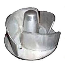
The McCrometer SPI Mag 3000 insertion electromagnetic flow meter is suitable for clean or dirty water flow measurement.
AMS Instrumentation & Calibration Pty Ltd
https://bit.ly/4hb3yL3


The wenglor sensoric group offers a complete range of components for an image processing system to solve individual vision applications.
Treotham Automation Pty Ltd
https://bit.ly/4hx0wAO


The SAMOS PRO MOTION is an expandable safety controller with the additional functionality of motion monitoring up to Cat 4 and SIL 3/PL e.
LAPP Australia Pty Ltd
https://bit.ly/4jEoWKu


The F200 solar-powered remote level monitoring device offers real-time monitoring of industrial liquid tanks and critical assets across water, fuel and chemical storage facilities.
Metromatics Pty Ltd
https://bit.ly/4aNdQPd


As one of the world’s largest meat producers, Danish Crown faces challenges in handling and palletising products on a larger scale. The need for staff can vary depending on the season and market demand, making it difficult to fill positions, especially during peak periods. This often leads to reliance on employee substitutes or additional staff, which can be a cumbersome process. These challenges have prompted Danish Crown to seek more innovative solutions.
At one end of the production line, an employee would pack eight bags of grill sausages into cardboard boxes, pass them through a taper, and then manually stack the boxes onto a pallet at the other end of the production line. This process, while essential, can be time-consuming and physically taxing for the employees.
There is a continuous flow of 20 different products, all packed in the same box but with varying weights, which requires quick adjustments when a box with new contents needs to be palletised. At the same time, traditional manual palletising methods can be time-consuming, physically demanding and risky for the employees.
In 2023, the factory in Svenstrup introduced a UR10e cobot from Universal Robots (UR). Since then, two more of the same type have been added to two more of the factory’s flow packer conveyor lines.
The three cobots have been implemented in collaboration with the Danish distributor Bila, which specialises in customised palletising solutions. For Danish Crown, the company used a Safe&Light Foam Vacuum Gripper from UR+ partner Joulin, which is installed with software developed by Bila’s technicians specifically for Danish Crown based on the dimensions and weight of the boxes.
Bila’s software solution consists of an operator interface that overlays the UR software and is programmed for the boxes, depending on their contents, as they move through the flow packing conveyor. The user-friendly programming is designed to simply let the operator at the conveyor press a button to switch from palletising one product type to another.
When an employee packs the eight bags of grill sausages today, they are still sent through a taper as before. However, the UR10e robot now handles the task of placing them on pallets.

“We are producing the same amount as before, but we are doing it much more efficiently because we have brought in the robots to assist with palletising. This means that employees no longer have to lift more than absolutely necessary,” said Lean Manager Jonas Salk.
Before Danish Crown installed the robots, peak periods typically required 15 employee substitutes — positions that were difficult to fill. This number has now been reduced to nine, and simultaneously, overall equipment effectiveness (OEE) has increased by a total of 19% across the three lines since the cobots were installed.
Maintenance technician Emil Lykholt also notes that the help from the robots has made the workflow easier.
“The production has become more efficient, and working with new equipment is enjoyable,” he said. “The robots were also easy to install and didn’t require more specialised training than a two-hour course.”
Due to the user-friendly program and the software solution, it is easy for everyone to manage the robot at operator level. They were instructed on how to start, stop and reset the robot to begin a new program.
“Usability has been our key focus in developing the software for the palletising solution at Danish Crown,” said Brian Spetzler, Product Manager at Bila. “It needs to be easy for any operator to start the cobot at the end of the conveyor, stop it if necessary, and reset it when a new type of product needs to be palletised.”
The collaboration between the robot and employees also influenced Danish Crown’s choice of the UR10e for its factory in Låsby, where another robot has been installed. Salk believes that Danish Crown will benefit from cobots in various areas of production, especially because they reduce the need for heavy and unnecessary lifting by employees.
“We see many opportunities with collaborative robots in various parts of production and at our other factories, where we can eliminate heavy lifting for employees and leave it to the robots,” Salk concluded.
Universal Robots www.universal-robots.com
Emerson has announced the TESCOM AGI BR Series Flushing Ring, a packaged solution for flushing and bleeding applications in petroleum refineries, biofuel refineries and petrochemical facilities. By providing a complete, modular valve assembly with a single part number, the AGI BR Series flushing ring is designed to streamline ordering and allow for easy reordering with user-specific test requirements. Both traditional BRS ‘sandwich’ and BRW ‘wafer’ style rings are available, as well as the BR7 ‘integrated bonnet’ design, which includes the bleed/flushing functions in the flange ring itself.

Most flushing ring devices are sold as separate components and assembled in the field. This often involves on-site welding and nondestructive examination (NDE) requirements such as pressure testing, positive material identification (PMI), dye-penetrant and radiography. In comparison, the AGI flushing ring includes valve assembly, welding, painting and testing in one comprehensive, compact package.
The AGI flushing ring meets piping and instrument class requirements according to the ASME B16.34 standard and is suitable for installation in processes requiring flushing of residue in front of diaphragm seals such as distillation towers, hydrotreaters, coking towers, reactors and separators. Fugitive emissions bonnets and ball valves that follow ISO 15848-1 and 2 are also available.
The TESCOM AGI flushing ring features flanged connections that are available in a range of sizes from 1 to 6 ″ , pressure class ratings from 150# ANSI to 2,500# ANSI, and temperature range options from -192°C to 538°C. Additionally, Emerson can provide custom variations and NDE testing to meet specific project requirements.
Emerson www.emerson.com/au/automation

The HYDAC Flow Rate Transmitter EVS 3100 for Oils & Viscous Fluids is designed for precise monitoring of oils and viscous fluids in industrial applications. The advanced sensor helps to provide optimal performance and reliability, offering high accuracy in viscosity measurements to maintain system efficiency. Its robust construction is suitable for harsh environments and it integrates seamlessly with existing systems for simple installation.
The Flow Rate Transmitter EVS 3100 can measure viscosities up to 100 cSt, operates according to the turbine principle and provides a 4–20 mA analog signal. Two G1/4 threaded holes in the turbine housing provide connections for additional devices such as temperature or pressure transmitters.
The Flow Rate Transmitter EVS 3100 is suitable for use in hydraulic systems, lubrication monitoring and industrial fluid management, to help enhance equipment performance, reduce maintenance costs and extend machinery lifespan.
HYDAC International www.hydac.com.au


The Microsonic MIC+ series of ultrasonic sensors offer a sensing distance of up to 8 m, making them suitable for diverse industrial environments, from manufacturing to material handling. This range is designed to offer flexibility and adaptability, enhancing operational efficiency.
Programming the MIC+ sensors is streamlined and user-friendly, due to two accessible methods: directly via the LED display or through free-to-download programming software. This dual approach caters to varying user preferences and operational requirements, for an intuitive and efficient set-up.
The MIC+ series supports the synchronisation of up to 10 sensors. This capability is suitable for complex installations where multiple sensors must operate in harmony, reducing set-up time and increasing system reliability.
Each sensor features a clear digit display, providing real-time value outputs in millimetres, centimetres or percentages, simplifying monitoring and adjustments during operations. The availability of IO-link technology further enhances communication and data transfer, making integration into existing systems easier.
An enhancement for the MIC+ series is the LCA-2 link control adaptor, which simplifies the duplication of sensor settings. This feature is designed for applications requiring consistent replication of sensor configurations, thereby saving time and reducing potential errors.
Pacific Automation www.pacificautomation.com.au

Claroty
As all types of cyber-physical systems continue to proliferate across many industries, managing cyber risk will only become a more challenging responsibility.
All cybersecurity disciplines and personnel in all sectors share the same overarching goal: to reduce cyber risk. But for those in industrial and critical infrastructure sectors where cyber-physical systems (CPSs) underpin operations, that goal is spiralling out of reach.
Here’s one reason why: simply assessing and prioritising — much less reducing — cyber risk in CPS environments requires a departure from many of the conventional methods and solutions that have long enabled chief information security officers (CISOs) and their teams to manage cyber risk in information technology (IT) environments. And with an estimated 95% of CISOs in critical infrastructure sectors now responsible for securing not only IT but also CPSs, more and more are coming face-to-face with the harsh realities of this highly consequential situation.
Key types of industrial CPS include:
• Operational technology (OT) assets: such as PLCs, actuators and RTUs that are integral to manufacturing, power generation, transportation and other critical physical processes.
• Internet of Things (IoT) devices: such as the security cameras, motion sensors, and even vending machines found across myriad types of facilities and environments.
At its core, risk is a measure of the likelihood and potential impact of an undesirable occurrence. This simple definition is not specific to a CPS, cybersecurity, or anything else. It holds constant no matter

the circumstances and can easily be demonstrated via the following equation:
Risk = Likelihood X Impact where: Likelihood = Threat X Vulnerability
• Likelihood: This variable refers to the probability of an undesirable occurrence. It is the product of (and dependent on) its two sub-variables: threat and vulnerability.
• Threat: This sub-variable is the source or trigger of an undesirable occurrence.
• Vulnerability: This sub-variable encompasses flaws or circumstances that a threat could exploit to lead to an undesirable occurrence.
• Impact: This variable reflects the consequences of an undesirable occurrence.
RISK
Sunburn
Example risk factors
Example risk controls
Sunlight
• The sun’s existence
• Somehow destroying the sun
LIKELIHOOD
Circumstances that enable sunlight to cause a sunburn
• Being exposed to the sun
• Having fair skin
• Staying indoors during peak daylight hours
• Wearing sunprotective clothing and sunscreen

RISK CONTROLS ARE MEASURES INTENDED TO REDUCE RISK BY DECREASING THE MAGNITUDE OF AT LEAST ONE VARIABLE OF RISK.
The consequences of getting a sunburn
• Having a low pain tolerance
• Being predisposed to certain skin conditions
• Applying ice, aloe vera, or other topical treatments that help soothe sunburn
• Seeing a dermatologist
The above equation is not intended to be interpreted in a mathematically literal sense, but it does highlight a mathematically accurate truth: if just one of the equation’s variables were to be eliminated (ie, assigned a value of zero), then the risk in question would also be eliminated.
Although it is nearly impossible to truly eliminate many — if not most — types of risk, the basic principles of risk management shed light on how to reduce it: apply risk controls.
Risk controls are measures intended to reduce risk by decreasing the magnitude of at least one variable of risk. They typically aim to offset risk factors, which have the opposite effect: they increase the magnitude of at least one variable of risk.
Let’s test these concepts by applying them to a very familiar type of risk: sunburn (see Table 1).
The sunburn example illustrates why costbenefit analyses (CBAs) are key to managing risk. It is usually neither feasible nor advisable to apply every possible risk control to every possible risk factor because the cost of doing so can outweigh the benefits. Indeed, destroying the sun would eliminate the risk of sunburn — but it would also eliminate life on Earth. As such, slightly less effective (and far less costly) alternative controls, such as sunscreen, are the ideal choice.
The sunburn example also highlights that some risk factors just cannot be feasibly eliminated or altered and, as such, must be accepted. Often referred to as risk acceptance, this sort of decision is notably
common for factors affecting the threat subvariable of our risk equation. Just like the sun, many threats will continue to exist in all but the most extreme circumstances — which is why prioritising controls that aim to reduce the vulnerability or impact variables of risk is usually the most effective and recommended approach from a CBA standpoint.
How we got here
The current CPS cyber risk landscape is rooted in the fact that, historically, the cybersecurity priorities of industrial environments were limited to air-gapping OT assets. No connectivity meant no need for cyber risk controls.
Today, it is commonplace for industrial CPS environments to be intertwined with their IT counterparts and the Internet. This norm is the product of digital transformation — particularly, the explosion of IoT, and other CPS technologies that organisations are increasingly implementing both alongside, and in place of, legacy OT assets.
The benefits of this transformation are undeniable, but it also exposes CPS environments to cyberthreats. Unfortunately, the connectivity such threats exploit is growing faster than efforts to secure it, suggesting the CPS cyber risks with which practitioners must contend are worsening. Let’s take a closer look at the numbers behind these conditions.
Primary Function
Enable and control the flow of data and information
Just as the above figures might suggest, the adoption of digital transformation initiatives that create or expand connectivity between IT and CPS environments has been a key factor in why responsibility for CPS cyber risk management has shifted largely to ITfocused cybersecurity practitioners in recent years. These conditions are also why many of the ways in which CPS differ from IT are often not only overlooked — but are further complicating efforts to secure CPS.
Table 2 details some of those key differences and their implications for cyber risk.
An ideal CPS cyber risk management program is one that effectively and efficiently assesses, prioritises and reduces the CPS exposure to cyber risk. Starting such a program doesn’t happen overnight; it’s a journey.
Begin with asset discovery
It is nearly impossible to manage CPS cyber risk without visibility into all assets comprising your CPS environment. Discovering those assets should be phase zero of your CPS cyber risk management journey because it is foundational to all subsequent CPS cyber risk controls. Here’s a high-level overview of an asset discovery strategy:
1. Define visibility goals
Align with stakeholders on your current CPS
Enable and control critical physical processes
Typical Composition
Cybersecurity Priorities
Standard computers, servers, and other IT assets that use standard systems and protocols
Confidentiality, integrity, and availability of data and information
Downtime Tolerance
Generally high
Nonstandard, complex, inherently fragile assets that use legacy systems and proprietary protocols
Availability, integrity, and safety of critical physical processes
Very low or non-existent
Cyber risk management can physically impact CPS, the critical processes they underpin, and/or the safety of operational personnel
Most CPS are incompatible with (and thus invisible to) standard cybersecurity tools, making them exceedingly tough to discover — much less protect
CPS priorities (and personnel) often conflict with standard cybersecurity priorities, further complicating efforts to protect them
Cyber risk controls requiring downtime (such as patching) are often infeasible to implement in CPS environments
visibility and cybersecurity objectives. Using those insights, define goals for CPS visibility — the first of which should be to gain a full CPS inventory as the foundation of your CPS cyber risk management program.
2. Choose discovery methods
Next, determine which asset discovery methods will fulfil your CPS visibility goals, and then select a reputable vendor that supports them all. You will likely need to combine several of the following methods to discover all CPSs in your environment:
• Passive monitoring: leverages switches and ports in the environment to copy traffic, which is sent to a server for analysis to identify the CPS present
• Active queries: targeted queries in the asset’s native protocol to discover CPS in the environment.
• Project file analysis: parses project files on components of CPS environments, and doesn’t require direct connectivity.
• Host-based discovery: installs a file on ‘host’ assets in the CPS environment, executes the file to collect details from hosts and nearby CPS, and then dissolves the file.
• Integration-based discovery: extracts key CPS details from the environment’s existing infrastructure, such as switches, firewalls etc.
3. Implement discovery methods
Working with your chosen CPS security vendor, execute your discovery methods until you can verify that all CPS technologies have been populated within your centralised CPS inventory.
4. Enrich CPS profiles
Validate that your CPS inventory provides a fully enriched profile with a granular list of details for each asset in your environment. If key, asset-level details are missing, overlay an additional discovery method to fill in the gaps.
Ensure you can accurately score your CPS cyber risk posture
Nearly all CISOs in critical infrastructure sectors are now expected to ensure their organisation’s CPS cyber risk posture is accurately reflected in the broader risk score shared with executive leadership. Aside from full CPS visibility, this also requires a risk scoring mechanism that:
• Reflects the broad range of risk factors and controls in the CPS environment: Every CPS environment has various factors and controls that contribute to its cyber risk posture —

and as such much be considered and quantified by the CPS cyber risk scoring mechanism in order for the scores it delivers to be accurate.
• Is flexible, customisable and transparent: Your CPS environment is unique, which is why your risk scoring mechanism must enable you to customise how different variables are weighted based on what matters (or doesn’t) to your organisation.
• Scores cyber risk at multiple levels: Different levels of risk scores support different use cases.
Score levels should include:
• Asset risk scores: Each asset in your CPS environment requires a cyber risk score, reflecting the likelihood and potential impact of a cyberthreat compromising that asset.
• Site risk scores: The average cyber risk score of all assets at one of your CPS environment’s sites reflects the CPS cyber risk posture of that site.
• Environment risk scores: The average cyber risk score of all assets across all sites comprising your CPS environment reflects your organisation’s CPS cyber risk posture.
Use risk scores to prioritise and assess the impact of controls
The accuracy of a CPS cyber risk scoring mechanism is critically important because the scores it generates should be used
as the basis for determining which cyber risk controls to deploy, how to prioritise them, and how to assess their impact on the CPS environment. These scores can be particularly useful for helping answer questions such as:
• Dozens of assets in my CPS environment are affected by the same CVE; which should I remediate first?
• How should I allocate my budget for cyber risk controls between the various sites comprising my CPS environment? To what extent has my network segmentation initiative affected my organisation’s CPS cyber risk posture?
Consider the operational limitations of controls
As noted earlier, the OT and other assets that comprise CPS environments not only underpin critical physical processes but they are also largely incompatible with standard cybersecurity approaches. Many of the controls commonly used in IT environments aren’t feasible to implement for all CPS in all circumstances. Such limitations can vary widely across assets and environments, but common ones include:
• Vulnerability scanning: Solutions that are widely used to scan IT assets for CVEs generate too much traffic to be safely used in CPS environments. Instead, use a CPS-specific solution that passively correlates asset details with CVE databases to pinpoint vulnerable CPS.
NEARLY ALL CISO s IN CRITICAL INFRASTRUCTURE SECTORS ARE NOW EXPECTED TO ENSURE THEIR ORGANISATION’S CPS CYBER RISK POSTURE IS ACCURATELY REFLECTED IN THE BROADER RISK SCORE SHARED WITH EXECUTIVE LEADERSHIP.
• Patching: Patching any vulnerability typically requires downtime, which most CPSs cannot tolerate due to the processes they underpin. Instead, consider alternative cyber risk controls, such as network segmentation, to compensate for the risk at hand without downtime.
• Endpoint security: Antivirus, EDR and other types of standard endpoint security solutions utilise agents, which tend to be incompatible with many types of CPS. Just as with patching, network segmentation and other alternative controls should be considered instead.
Keep tabs on the regulatory landscape
Another key component of any CPS cyber risk management program is the cybersecurity regulatory landscape, which has evolved considerably in recent years amid increases in the frequency and impact of cyber incidents affecting CPS environments. There are now more CPSspecific regulations than ever, so it’s crucial to track those relevant to your organisation, their requirements for compliance, and how audits work.
As all types of CPS continue to proliferate across critical infrastructure sectors, managing CPS cyber risk will only become a more crucial — and, likely, more challenging — responsibility for cybersecurity practitioners. The insights and tips shared throughout this article are intended to help you grasp some of the basics of this responsibility, but it is crucial to remember that, above all else, it’s a journey.

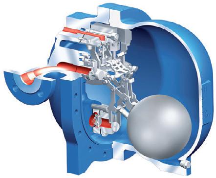
offers a revolutionary solution for the municipal wastewater and stormwater well by lifting influent directly from the inlet to the discharge while detecting the entry point, without water loading. Because the system handles influent

Contact


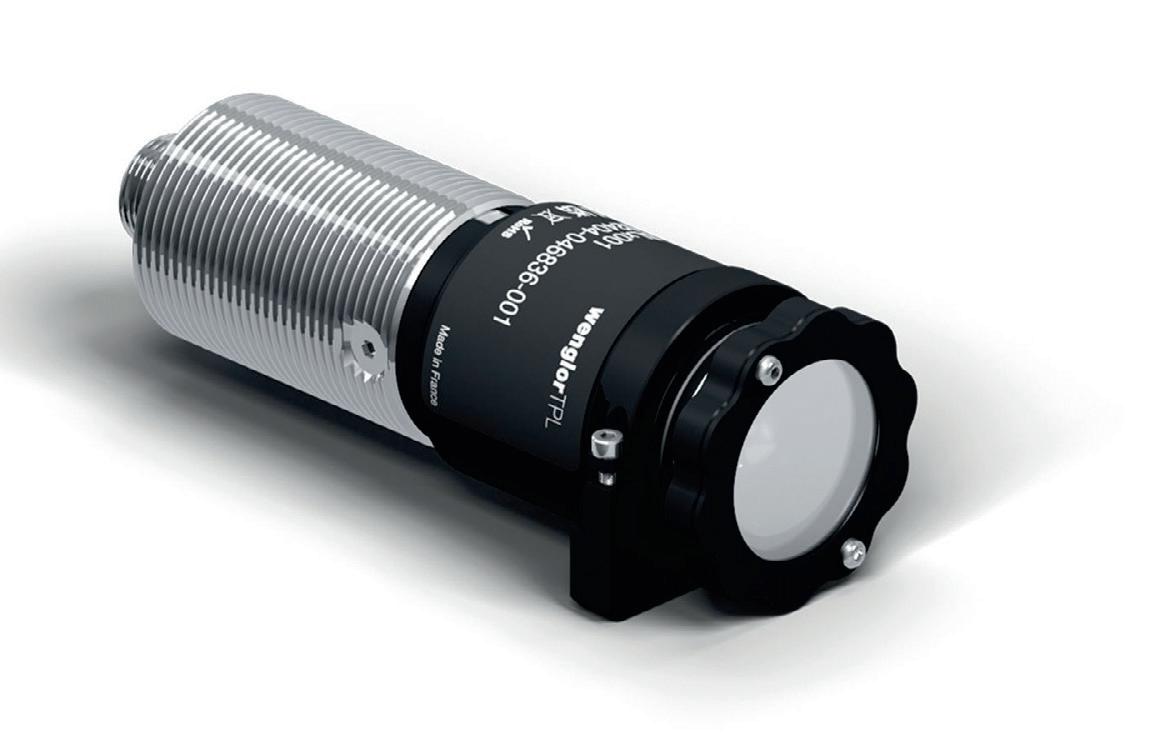
Wenglor’s spotlights with lockable zoom lens offer a variable beam angle in the range of 4° to 26° with constant homogeneity to enable improved illumination. Flash mode overdrive with an illumination intensity of up to 360,000 lux, the robust housing and flexible mounting options make the spotlights suitable for application illumination in industrial image processing. Available in white light, red light and infrared light, the spotlights help achieve precise alignment of the visual field with position repeatability, to provide optimal illumination with high intensity. They can also be used with a compatible polarisation filter to reduce reflections from shiny surfaces.
The robust aluminium housing with IP67 protection against environmental influences and the M30 thread allows quick and easy installation. Camera brackets provide flexible mounting options for minimal installation effort. The M30 proximity sensor brackets enable space-saving integration, with the additional option of using swivel brackets.
Treotham Automation Pty Ltd www.treotham.com.au


The xiX-XL camera series from Ximea are fitted with high-quality Sony sensors that are integrated into a camera design that is specifically developed for applying in embedded vision and multicamera setups. The PCIe interface used for interconnection allows users to fully utilise the sensors’ speed and synchronisation potential.
Designed for applications such as machine vision, quality inspection and surveillance, the cameras are engineered to offer high performance while maintaining minimal size, weight and power (SWaP) requirements.
The xiX camera series offers a bandwidth of 32 Gbps using a high-speed PCI express Gen3 x4 lane interface. It allows the integration of the newest generation of large format Sony sensors (IMX455, IMX461 and IMX411) with up to 6 fps at 151 Mp resolution, 66.7 mm diagonal, or down to 18 fps at 61 Mp resolution. The cameras offer up to 60 x 47 mm optical format and a 16-bit A/D conversion.
A housing concept with a detachable sensor head optimises heat dissipation to improve the image quality and simplifies integration into tight spaces. It is possible to detach the sensor head from the body with flex cabling and use optical cables up to 100 m in length. Synchronisation is achievable via programmable opto-isolated I/O and the cameras are compatible with Windows, macOS, Linux, ARM and NVIDIA Jetson modules.
SciTech Pty Ltd www.scitech.com.au


We specialise in Industrial Test & Measurement Sensors/Transducers: Pressure, Temperature, Laser Displacement, Flowmeters, Water Meters, Pneumatic Controls, Joysticks, Rotary Encoders, Accelerometers and LVDTs
Instrumentation: Dataloggers, DAQ Systems and Digital Display Units.


IDEC Corporation is launching the FS1B safety controller, an upgrade of the FS1A device providing additional features. The FS1B lets designers create streamlined machine safety systems with multiple safety channels by using any of 24 preset safety logic strategies selected with DIP switch configuration and no programming required.
Standard safety circuit designs often use many safety relays to accommodate multiple inputs from E-stop buttons, light curtains and other safety devices. The FS1B consolidates this functionality into a compact, standalone form factor, with convenient and reliable push-in terminals. DIP switches and a single ‘enter’ pushbutton provide quick and easy setting of the safety logic strategy, inputs and power off delay timer, and these settings can be locked in with a protective cover secured by a marked cable tie to prevent accidental changes. Coloured LEDs and 7-segment numeric displays provide clear at-a-glance device and I/O status.
The FS1B includes 12 universal discrete inputs assignable as up to six safety channels. Each of the 24 built-in safety logic strategies are certified by a trusted independent body to streamline the overall approval process for machinery certification.
The FS1B carries applicable IEC 61508, ISO 13849, UL508 and other approvals. Depending on the application, the safety performance can be up to SIL 3, PLe, Category 4. Powered by industry standard 24 VDC, with a wide operating temperature range of -10°C to +55°C, the FS1B is suitable for most control panel locations, whether on-board or external to the protected equipment.
IDEC Australia Pty Ltd www.idec.com/australia


Pizzato CS AM series safety modules are designed for motor speed and standstill detection. Improved features include sensorless speed monitoring, more sophisticated motor control through parameterisation of the modules via software, and the ability to monitor motor operating data in real time.
The Pizzato CS AM series safety modules now include three different types, each dedicated to different control tasks.
The CS AM1 is designed for motor standstill monitoring and the CS AM2 is for monitoring of motor speed and direction of rotation, while the CS AM3 combines the functionalities of both CS AM1 and CS AM2.
The CS Am Configurator software allows all relevant project information to be entered and the required function selected and configured for each input and output of the module. Previously saved configurations can also be downloaded.
Parameters for the detection of motor standstill can be set, thresholds for minimum and maximum speed thresholds defined, and the detection of the motor’s direction of rotation enabled.
The software can also monitor the status of the module’s outputs, the residual voltage detected on the phases, and the speed and the direction of rotation of the motor in real time.
Leuze electronic Pty Ltd www.leuze.com.au
Operator interfaces serve as the vital connection between human operators and industrial machinery, enabling control, monitoring and interaction on production lines. HARTING’s latest series of pushbuttons, emergency stop switches, and other operating elements are designed to combine safety with aesthetics. As the cornerstone of human-machine interaction, operator interfaces must be safe, intuitive and reliable. This series builds upon the visual appeal of HARTING’s previous har-port line, creating a unified and userfriendly control system. The operating and command devices are available as status lights, pushbuttons, key switches, selector switches and emergency stop switches.
All models are designed for enclosure mounting and come in two sizes: a 22.3 mm diameter cutout suitable for automation, machinery and robotics, and a 30.5 mm diameter option for transportation applications. In addition to industry-standard housing interfaces, users now have access to reliable and robust operating elements from a single source through HARTING.
HARTING Pty Ltd www.harting.com.au


Herman Coello*

There is room for both ultrasonic and radar level measurement technologies in the water and wastewater industry, but which should you choose?
If your head spins after reading how amazing one level measurement technology is in comparison to another, understanding the key attributes of these technologies and their applicability to specific processes may help to clear the waters.
When it comes to devices that monitor the level of clean or not-so-clean water — be it in filter beds, wet wells, lift stations, water towers, chemical tanks or open channels — ultrasonic technology emerges
on top, followed by radar. It’s true that some level application challenges can be solved by more than one level technology. Yet, no single technology can handle every process, regardless of cost, how powerful the instrument is or how new the technology is.
Ultrasonic level technology has been proven for decades in the water and wastewater industry. Even though both ultrasonic and radar technologies have the required muscle, ultrasonic instruments also possess the intelligence to comprehensively
meet industry needs. This is important to keep in mind when considering which technology is best for a given application. Simply comparing the attributes of ultrasonic versus radar devices may not be the best course of action. Rather, consider their features within the context of where and how the technology will be used.
For example, if you are trying to decide which instrument is better suited for monitoring level in a lift station and controlling pump operation, it won’t be helpful to learn that radar transmitters can function in a vacuum, withstand high pressures and drastic temperature changes, and are capable of handling temperatures more than twice as high as ultrasonic-based level devices. Such features sound impressive, but none of these conditions exist in lift stations. The marketing of extravagant attributes tends to clutter the message and adds to confusion within the industry.
To gain clarity, rely on what you already know and evaluate whether a newer technology offers tangible benefits. If your current level solution has proven reliable, is it really worthwhile to make major changes due to factors like ease of commissioning or cost? Once a reliable instrument is set up and configured, commissioning becomes secondary. And if the price of a newer model is attractive, consider what might be lacking in terms of functionality. A lower price does not imply lower performance, but the scope of operation is likely to be limited to simpler functions. Thus, in considering an alternate technology, make sure that the new solution will not open the door to a set of problems that weren’t present with the proven technology already in place.
Both ultrasonic and radar are noncontacting level technologies, which means that they measure level through the air using the time-of-flight principle. As a result, it is not necessary for this type of level device to contact the surface of the material. In contrast, a contacting technology is equivalent to the dip stick used to check the oil level in your car. Capacitance and guided wave radar are examples of contacting level technologies. A significant benefit of non-contacting level instruments is that they are truly low maintenance. There’s seldom a need to clean

the transmitter section of the instrument (the antenna, emitter, lens or transducer face) because, in most cases, the material level remains some distance away from the sensor. In a wet well or a lift station, the clearance between the highest level and the sensor is usually a few metres.
In certain applications, however, it is possible for build-up to occur. Although these instruments are designed to be non-contacting, water treatment facilities must deal with overfilling due to excess water during severe storms, cyclones, flooding, etc. In such instances it is possible for level devices to become submerged. The potential for build-up increases if an instrument regularly encounters debris or sticky substances during submergence. Additionally, condensation can form on the sensing area of the instruments due to large temperature swings (warm days and cold nights) inside tanks, wells or any vessel not
in a controlled environment. Understanding how ultrasonic and radar technologies deal with these adverse conditions is crucial in making the right choice.
Under submergence conditions, the best-case scenario for a level device is to consistently report a maxed-out level measurement indicating the abnormality. However, many instruments yield random values when submerged and thus aren’t reliable. With recent technological advances, some radar level transmitters fare better under these conditions because they are capable of holding a high level. But there remains the issue of build-up over time. A small amount of non-conductive build-up is usually not a problem for radar devices, but when build-up increases, it can trap more conductive debris. Signal degradation and random operation will ensue. Since radar transmitters generate electromagnetic waves with no electromechanical action, there
BOTH ULTRASONIC AND RADAR ARE NON-CONTACTING LEVEL TECHNOLOGIES, WHICH MEANS THAT THEY MEASURE LEVEL THROUGH THE AIR USING THE TIME-OF-FLIGHT PRINCIPLE.

is no inherent mechanism to reduce the accumulation of build-up.
Ultrasonic technology offers both transmitters and controllers for level and open-channel flow monitoring. Like radar transmitters, ultrasonic transmitters are compact devices encapsulating the electronics and sensing mechanism in one instrument. In contrast, ultrasonic controllers consist of a receiver and a transducer, and only the completely sealed transducers are placed inside the process with no sensitive electronics exposed to the conditions in a lift station, wet well or tank. Additionally, unlike radar transmitters, ultrasonic transducers create electromechanical action during the process of ultrasonic wave generation. The mechanical action on the face of ultrasonic transducers renders them inherently self-cleaning, thereby reducing the amount of build-up and condensation that accumulates on the face of the
sensor. When submergence conditions are prevalent, transducers can also be fitted with a submergence shield or hood. Because two bodies can’t occupy the same space, the air trapped inside the hood prevents debris from reaching the face of the sensor. Also important is the fact that, due to the mechanical action taking place, the signal signature during submergence can be differentiated from that during normal operation. Thus, the controller knows to keep the level locked at over 100% to indicate the submergence event. This happens reliably, time after time, with no need for maintenance after the event.
It is sometimes argued that radar technology is more accurate than ultrasonic because it is not affected by wind and because the speed of sound varies with
changing temperatures. However, for more than 20 years ultrasonic transducers have been manufactured with integral temperature sensors to monitor the surrounding temperature. This allows ultrasonic technology-based transmitters and controllers to correct for the speed of sound and accurately track the level in a vessel or the head in an open channel. Nevertheless, it is a good practice to use protective covers on all instruments to shield them from direct sunlight and avoid heating up the electronics.
There is an error associated with level measurement for every degree change in temperature. But, thanks to advancements in design that include digital filtering and signal processing algorithms, some ultrasonic level controllers can deliver accuracies down to ±1 mm. With regards to extremes, it will take several minutes for an ultrasonic level sensor to acclimate to a drastic temperature change — for example, when the unit is brought from a control room or storage into an environment that is significantly hotter or colder — but thereafter it will consistently provide correct level measurements.
In addition, remember that accuracy depends on more than just temperature’s effect on electromagnetic or sound waves. Radar transmitter accuracy is also affected by the temperature of the electronics, and it too can be correlated to an error per degree change. Add to the mix the expansion and contraction of vessels and substances themselves, and millimetre differences in accuracy become trivial. The key question to ask is how crucial accuracy really is within the context of your industry and the material being monitored. In general, tight accuracy is not considered to be overly important for level measurement in water tanks, chemical tanks, lift stations, scum wells, filter beds or clarifiers.
An area where accuracy has more relevance is flow measurement. In some cases, primary devices (weirs and flumes) are fitted with secondary devices (level instrumentation) to monitor and bill customers according to how much they discharge into a municipality’s collection infrastructure. Additionally, reconciling the influent and effluent flows at a plant (eg, due to water losses from major leaks) may require more accurate measurement than at wet wells.

In the past, radar technology was more expensive than ultrasonic since radar transmitters. However, the newest compact radar transmitters on the market have not only decreased in cost and size, but their operating frequencies have also increased significantly. The clear benefit is that radar instruments operating in the 80 GHz range can produce a narrow signal without the need for large antennas. In constricted spaces where many objects can obstruct the transmitted and returned signals, a narrow beam suffers less degradation from unwanted interference. Additionally, radar transmitter setup can be carried out quickly for simple applications, meaning that the devices can be up and running within a few minutes.
If a level indication is all that’s required, a simple radar level device can certainly handle the task. But by design, radar and ultrasonic level transmitters alike have a limited scope for the water industry beyond level measurement. Some of these transmitters can also provide lowresolution flow measurements, but not to the extent and complexity that is possible with ultrasonic controllers. Today, the market offers some economical radar transmitters that can be connected to a level controller for additional functionality — but doing so minimises or eliminates the cost advantage associated with these less expensive radar
transmitters and especially if the level controller just offers basic operations. Further complicating matters is the fact that both the radar sensor and the level controller need to be configured independently for proper operation.
If it is determined that radar technology is more suitable because there are gases or vapours present in the environment or because the application has too many obstructions impeding a good signal path, then a compact radar transmitter with narrower beam signal is a sensible choice. Advanced level controllers can also add advanced functions for various water and wastewater applications.
Before committing to a lower-priced level solution, it is important to carefully consider what will be gained or lost to avoid creating gaps in functionality that didn’t previously exist.
There is room for both ultrasonic and radar level measurement technologies in the water and wastewater industry. Ultrasonic devices have been relied on by the industry for several decades, and the technology has evolved over the years to meet and exceed the demands of this market. Both technologies offer the clear benefit of being non-contacting and, therefore, low maintenance — but in the world of level measurement, there are additional factors to consider. Understanding the process and its unique challenges (submergence,
ULTRASONIC DEVICES HAVE BEEN RELIED ON BY THE INDUSTRY FOR SEVERAL DECADES, AND THE TECHNOLOGY HAS EVOLVED OVER THE YEARS
build-up, condensation, pump demands, etc.) will provide the clues to selecting the ideal instrumentation for ensuring seamless operation.
Don’t let enticing attributes such as high accuracy and low cost be the sole factors that persuade you into choosing one level technology over another. The key is to be objective about what your challenge entails. When unsure, a good rule of thumb is to work with a supplier who offers a wellbalanced product range backed by years of experience in the field — experience that can provide you with much-needed clarity.
*Herman Coello is the Level Product Manager for Siemens Industry, Inc. based in Arlington, Texas. His experience with level instrumentation spans over 30 years, and he has been heavily involved with training customers, sales and marketing representatives on Siemens radar and ultrasonic transmitters and controllers.

Siemens SIMATIC HMI Unified Basic Panels feature a modern design with a robust, tempered glass front that allows operation with gloves. The glass front also includes an anti-reflective layer for high display quality. The panels are equipped with advanced features such as the detection of operating errors (eg, touching the screen with the ball of the hand), high electromagnetic compatibility and a zoom range that allows detailed viewing in curve displays, web control and document display. The panels also support scrolling in lists, such as notification displays, text lists and documents, and offer two-handed operation for enhanced safety.
The panels are designed to operate under various environmental conditions, with diverse mounting types, certifications and device variants to meet specific industrial needs. This includes sizes ranging from 4″ to 12″ , all offering the same number of hardware interfaces and functionality.
Each Unified Basic Panel includes an integrated web client, providing flexible remote access for operation and monitoring. The panels are equipped with a proprietary operating system based on SIMATIC Industrial OS, which offers high security by allowing users to deactivate or uninstall unnecessary interfaces and system apps. Firmware and security updates can be managed via the Siemens TIA Portal or the SIMATIC Automation Tool, so that devices remain secure and up to date.
The panels are configured using WinCC Unified software — also part of the TIA Portal and enabling the integration of data and communication with other Siemens controllers and HMI devices.
APS Industrial www.apsindustrial.com.au


Bosch Industriekessel GmbH, part of the Bosch Home Comfort Group, has been making industrial boilers since 1865, and specialises in producing steam and hot water boilers, including large-scale units that generate up to 55 tonnes of steam per hour.
“We’ve been making industrial boilers for a long time and now stand as market leaders in our segment,” said Klaus-Hinrich Koch, Development Engineer at Bosch.
A key factor in Bosch’s success is the ability to evolve with the times, offering modern solutions such as remote management of boilers and a range of decarbonised, electrical boilers: “We recently worked with a fish factory in Iceland where they produce their own packaging material using steam from one of our electrical boilers, powered by 100% green electricity,” Koch said.
Bosch has been using industrial networking technologies from HMS in its boilers since 2011, when it started to include Anybus X-Gateways with its Boiler Control (BCO) and System Control (SCO) systems. The BCO manages the boiler itself, while the SCO oversees the entire boiler house, automating systems like feed water conditioning, condensate return and fuel monitoring.
“For a typical installation with two boilers, each boiler has its own BCO, with a dedicated connection to the SCADA system,” Koch explained. “Additionally, the SCO manages the overarching systems and is also connected to the SCADA system. In this scenario, we use three Anybus gateways: one for each BCO and one for the SCO.”
The Anybus gateways play a critical role in ensuring connectivity.
“If a customer wants data from our boiler system, we use an Anybus gateway to connect their SCADA system to our BCO or SCO. Our systems use Profinet, but the customer might use Modbus/TCP, RTU or Profibus, so we use the gateway to convert the protocols,” Koch said.
But the gateways don’t just offer protocol conversion; they also enhance security.
“For maximum security of our systems, it is important to decouple system control from data communication. This helps avoid security-critical misuse from outside the system while maximising the integration of data into the local automation system,” Koch said. “That is why we still use a gateway even
if the customer uses Profinet. For security reasons, we have to separate the boiler house network from the customer’s network.”
To simplify the installation at the customer site, Bosch preconfigures the gateways for its side and, if provided with the necessary information, also for the customer side before shipping. The company also conducts comprehensive testing before anything leaves the factory.
“We want to spot and resolve problems before we deliver anything. Trying to solve issues later is very time-consuming and expensive,” Koch said.
In the interest of keeping up with the latest technology, Bosch is currently transitioning from the Anybus X-Gateways to the next-generation Anybus Communicators.
“We’ve delivered some boiler systems with the new Modbus/TCP-toProfinet and Profibus-to-Profinet Communicators,” Koch said. “The web-based user interface makes configuration easier. It’s quicker to install and also easier to understand. We also use the diagnostics tab in our test system to check the connections during our integration tests.
“The Ethernet connection is also useful. I can put the Communicator in the same address range as our PLC, program our PLC, and see the connection on the Communicator’s webpage. It’s easier because I don’t have to change addresses.”
Improvements in cybersecurity capabilities have also come in handy for Bosch.
“Cybersecurity is becoming increasingly important, and the Communicator helps us improve security,” Koch said. “It provides an extra layer of security by segmenting the network, but I particularly like the small security switch on the Communicator. It prevents changes to parameters, addresses and so on, in an easy way. During our testing process, we performed some hacking tests, and the Communicator passed them all. It was not possible to access our PLC from the customer’s side of the network, so the security features worked well.”
HMS Industrial Networks hms-networks.com

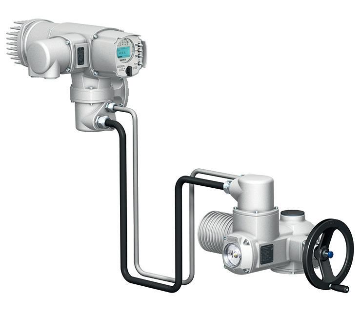
Of the three main components typically contained in a SIF (Safety Instrumented Function), the logic solver is the most critical. The logic solver is responsible for determining whether dangerous conditions have been met and is responsible for the final element’s ultimate effect on the mitigation function or strategy.
Two types of products have become widely accepted tools in implementing the logic solver component in functional safety applications. They are the programmable logic controller, or safety PLC, and the single-loop logic solver. The safety PLC, which is the generic name given to large point-count logic solvers, offers much more flexibility but does so at a significantly higher price and with greater complexity, while the single-loop logic solver is more limited in its capability but can adequately reduce risks and meet safety system requirements with less expense and complexity.
Safety PLCs certainly fill key requirements within functional safety, especially as they relate to large point and loop counts and TMR (triple modular redundant) applications, or where the need exists to sync or network multiple safety logic solvers together to address a complex safety function. Safety PLCs are very capable but come with an extremely high price tag and often require sophisticated programming, maintenance and documentation.
Conversely, there is the fully capable but smaller single-loop logic solver that handles one loop and just a few points. Like safety PLCs these are often IEC 61508 certified but have a much smaller footprint and cost far less than safety PLCs. Additionally, the programming is less complicated and does not require any software licensing.
This is where the logic solver gap lies: functionality, complexity, and cost between these two types of logic solver options are vast. While each certainly has its place, many functional safety applications require just

two loops, or three loops with six inputs and six outputs, and perhaps some simple 1oo2 or 2oo3 voting or maths. The safety PLC could certainly handle this, but is it overkill? Alternatively, single-loop logic solvers might be able to handle this with output relay wiring for voting, but point counts are limited and voting architectures can become convoluted with relay inter-wiring.
The Moore Industries SLA Multiloop and Multifunctional Logic Solver and Alarm fills this gap as a less expensive, less complex, multipoint, voting capable and IEC 61508-certified logic solver that allows safety practitioners the option that meets the functionality below that of the safety PLC but above the capabilities of the single-loop logic solver.
With up to seventeen I/O channels, simple voting configuration and enhanced maths/ logic capabilities typically found in costly and complex safety PLCs, the SLA can handle everything from simple alarming to complex logic schemes including 1oo2, 2oo3 or even 5oo8 voting architectures. Each of the SLA’s 16 alarms can be configured for High Availability or High Integrity, giving optimal control over shutdown strategies.
The SLA also offers a powerful, flexible, easyto-use equation/expression editor feature that uses spreadsheet-like formulas and prebuilt functions. An equation/expression editor quick reference is available on-screen to help ensure the quick and easy creation of these equations, or internal variables. Once built, these variables can be used as alarm input sources, analog output sources or even alarm suppression and reset triggers. Additional advanced functions like timers, running min/max registers, and custom curves are also available.
Confi gured with license-free FDT/DTM technology such as PACTware, the SLA meets a variety of logic solver needs and offers straightforward and quick setup with easy-to-use pull-down menus, checkboxes, and radio buttons.
While it is true that IO-Link is plug-and-play from a hardware perspective, it pays to do your homework on the software.
IO-Link is a digital communication protocol that enables the exchange of data between sensors, actuators and automation systems. It was developed under the direction of the IO-Link Consortium, and since 2009 has been standardised as IEC 61131-9. Today, IOLink is supported by hundreds of device manufacturers and used in countless industrial applications worldwide.
IO-Link is a standardised, bi-directional communication protocol supported on
sensors or actuators. It is not another fieldbus, but instead was developed to be as simple and universal as possible.
An IO-Link system consists of the following components:
• IO-Link devices: Intelligent sensors and actuators that communicate via the IOLink protocol, and can send and receive detailed information about their status, performance and environment.
• IO-Link Master: The heart of an IO-Link system, it is a central device that acts as a gateway between the IO-Link devices and the upper-level control system — such as a PLC or DCS — and coordinates

IN MANY CASES, IO-LINK MASTERS ARE INTEGRATED INTO VENDOR-SPECIFIC PLATFORMS, PROVIDING A UNIFIED INTERFACE FOR CONFIGURING THE ENTIRE AUTOMATION SYSTEM...
the communication and provides data integration with the main control system.
• Standardised cables: Standard, unshielded, 3-, 4- or 5-wire cables M12, M8 or M5 cables, making it easy to integrate into existing systems.
• Device description files: Each IO-Link device is provided with an IODD (I/O Device Description) file, which contains information about the device’s capabilities, parameters and diagnostics. The IODD file allows the IO-Link Master to correctly identify and configure the device.
IO-Link offers numerous benefits for industrial automation, particularly in sectors such as manufacturing, food and beverage, pharmaceuticals, and packaging, where real-time monitoring, diagnostics and flexible communication are essential.
Device diagnostics and monitoring
IO-Link allows for detailed diagnostics at the sensor or actuator level. This means that in addition to basic process data, the device can also transmit health and status information, such as temperature, or operating hours. This real-time diagnostic data is invaluable for predictive maintenance and reducing downtime.
Remote configuration
One of the most significant features of IO-Link is the ability to configure devices remotely. This capability is especially useful in environments where sensors and actuators are difficult to access, such as in hazardous locations or in systems with a large number of devices. Users can change device parameters without physical intervention, which reduces setup time and enhances system flexibility.
Standardisation
Since IO-Link is an open standard it is vendor independent. This means devices from different manufacturers can be integrated into the same system as long as they adhere to the IO-Link standard. This interoperability allows you to choose the best devices for your specific needs without worrying about compatibility issues.
Cost effectiveness
By using standard, unshielded cables for IO-Link communication, without individual
wiring back to the PLC, you can save on wiring costs. Additionally, the enhanced diagnostics and remote configuration capabilities help reduce maintenance costs by minimising downtime and manual intervention.
In greenfield sites considering digitalisation, IO-Link provides high functionality, with a good price/performance ratio. For brownfield sites, IO-Link can be an effective way to add digitalisation to improve efficiency and lower maintenance costs: Total cost of ownership is improved with efficiency improvements and cost savings during the lifecycle of a project.
Perhaps the greatest advantage of IO-Link is that you can mix and match sensors and actuators from any vendor to meet the needs of your process and your project budget, as long as they are IO-Link compatible. But there’s a catch: software compatibility.
The fact that IO-Link hardware is standardised allows for flexibility in device selection, but many users do not know that the software environment surrounding IOLink systems often requires careful planning.
While the hardware aspect of IO-Link is standardised — and users can mix and match sensors, actuators and masters from different vendors — there is one important thing to be aware of: the software used to configure, manage and diagnose IO-Link devices is dependent on the vendor of the IO-Link Master.
Each vendor typically provides its own configuration tools, integration methods and device management software. This is applicable to both the IO-Link masters and the field devices. This creates a situation where the choice of the IO-Link Master dictates the software available to configure the devices in the field, and the data that is available to the controller. The inverse may also be true where the higher-level software in use at the control system dictates the types of IO-Link Master that can be used.
Often, users will purchase IO-Link Masters from a vendor offering the best price, which will work fine with the end devices; however, they may run into difficulties configuring and commissioning end devices and the master itself.
Different vendors of IO-Link Master hardware offer their own configuration tools that are used to set up and manage the IOLink system. For example, companies like Siemens, Rockwell Automation, Balluff and IFM provide specialised tools that are tailored for their IO-Link Masters. These tools enable users to import IODD files for the connected devices, configure parameters and monitor device status; however, the interfaces and functionality of these tools can vary significantly, and the tool from one IO-Link Master vendor will not be fully compatible with another.
The software used with the IO-Link Master must also integrate with the fieldbus or industrial Ethernet system used at the higher levels of the control system. For example, if the control network is communicating over EtherNet/IP, then the IO-Link Master must be able to handle communication with the control system via EtherNet/IP. This can be as a single protocol available on the master, or as part of a multiprotocol software suite.
In many cases, IO-Link Masters are integrated into vendor-specific platforms, providing a unified interface for configuring the entire automation system, including IO-Link devices. This further emphasises the need to align the choice of IO-Link Master with the software in use at the higher levels of the system.
Additionally, while IODD files for IO-Link devices are standardised and available for all compliant devices, the quality, interpretation and display of these files within the configuration software can also vary from vendor to vendor.
The most discussed benefit of IO-Link is that it is plug-and-play. And while this is true from a hardware perspective — with standardised interfaces, IO-Link Hubs, IO-Link Masters, cabling and connectors — it is not necessarily true from a software perspective. As a user it is important to be careful to select an IO-Link Master that is compatible with your software environment.
So if you are planning on taking advantage of the many benefits of IO-Link, it pays to do your research before selecting your IO-Link Master device.

Registration is now open for the biggest precision engineering manufacturing show ever held in Australia.
AMW2025 is being held at the Melbourne Convention and Exhibition Centre (MCEC) in Melbourne, from Tuesday, 6 May through to Friday, 9 May 2025. Organised and run by the Australian Manufacturing Technology Institute Limited (AMTIL), AMW2025 will host over 400 organisations taking stands to showcase the latest manufacturing technologies, processes and support services.
The event, which will occupy 80% of the MCEC, will cover every aspect of manufacturing technology, from the largest machine tools to the smallest precision cutting tools. It will also include stateof-the-art support systems, software and accessories, and the myriad services essential to any manufacturing operation.
One of the many highlights of AMW shows is the Future Solutions Speaker Program, which begins on the first day of AMW2025. The various sessions have been hand-picked to cater to the industry’s varied
needs to tackle challenges and stay abreast of the latest trends.
“Come and hear from the best specialists in each field,” said CEO of AMTIL Lorraine Maxwell. “Our Future Solutions sessions will cover many aspects of manufacturing in Australia, as well as services surrounding and supporting our industry. We are all set for a great week.”
AMW2025 will offer a wider spectrum of technologies vital to the modern manufacturing business than has ever been brought under one roof at an Australian exhibition before. To help visitors to the show navigate such a diverse line-up of exhibits, AMW2025 will feature dedicated areas covering a range of specialised aspects of the modern manufacturing landscape:
• Additive Manufacturing Zone
• Australian Manufacturer’s Pavilion
• Machine Tools
Manufacturing Solutions
• Robotics and Automation
• Weld and Air Solutions
This is the ONE event showcasing the latest innovations, technologies and equipment in the advanced manufacturing
Where: Melbourne Convention and Exhibition Centre
When: 6-9 May 2025
sector. Explore new opportunities, meet, and network with industry leaders and technology experts, all under ONE roof at ONE show.
With so much on show at such a large event, the challenge for AMW visitors is taking in everything available. Fortunately, assistance is at hand: AMW’s organisers have teamed up with event management software experts Map Your Show to develop online tools to help people plan their visits. There will also be an AMW App to aid visitors in navigating the site. More details can be found on the AMW2025 website, so your movements at AMW can be mapped right now.
“I think it’s safe to say that every aspect of manufacturing today will be on display at AMW 2025,” added Kim Banks, Exhibition Director at AMTIL. “There will be something for everyone involved in manufacturing. Just ensure you set aside enough time to see it all.”
Be sure to visit Australian Manufacturing Week in Melbourne from 6–9 May 2025. This show is going to be massive!
Attendance is free and registration is required. Learn more and register today at www.australianmanufacturingweek.com.au.
The ICP DAS I-7018Z-G/S3 is a 10-channel thermocouple input module that supports current, voltage and thermocouple inputs, making it suitable for various industrial applications. It features automatic cold-junction compensation for each channel for consistent and stable temperature outputs. With high overvoltage and common voltage protection, the I-7018Z-G/S3 provides robust performance in harsh environments.
Each channel can be individually configured, and the module includes open thermocouple detection. Built-in dual watchdog timers enhance operational reliability, and it is compliant with CE, UKCA, FCC, RoHS and WEEE standards.
Overvoltage protection up to 240 VAC safeguards the device from electrical surges. Additionally, the M-7018Z variant supports both Modbus RTU and DCON protocols, providing easy integration into various industrial systems.
The I-7018Z-G/S3 is suitable for applications in factory automation, machine automation, remote maintenance, remote diagnosis and testing equipment.
ICP Electronics Australia www.icp-australia.com.au


Ella Averill-Russell, IICA Sydney Branch Manager
Technology is transforming industries by advancing sustainability, efficiency and resilience. Emerging trends like the circular economy and Power-to-X (P2X) technologies are at the forefront of this shift, influencing critical sectors such as food, mining and energy.
The circular economy is redefining resource efficiency by revolutionising how industries manage waste and materials. Advanced recycling systems, powered by AI and robotics, are tackling complex waste streams such as e-waste and industrial by-products, while blockchain ensures supply chain transparency and promotes sustainable sourcing. In food production, waste is being repurposed into alternative proteins and bioenergy. Mining operations are recovering critical minerals from industrial waste, and energy companies are developing battery recycling systems that extend the life of storage solutions. Biotechnology further supports this shift, converting organic residues into bioplastics, fertilisers and bioenergy.
Power-to-X technologies play a pivotal role in decarbonising industries by converting renewable electricity into fuels and chemicals. Green hydrogen production via electrolysis is accelerating its integration into industrial processes, fuel cells and synthetic fuels for hard-to-abate sectors like aviation and shipping. Innovations such as green ammonia for energy storage and Carbon-to-X processes — which turn captured CO2 into materials and proteins — are unlocking new opportunities while mitigating emissions.
The food industry is also undergoing a technological transformation to meet rising sustainability demands. Precision agriculture — supported by IoT sensors, drones and AI — optimises water and fertiliser use while increasing crop yields. Meanwhile, alternative proteins — such as lab-grown meat and fermentationbased solutions — are scaling up to address global food security. Technologies like blockchain and RFID are enhancing traceability across supply chains, while agrovoltaics combines renewable energy generation with farming to maximise land efficiency.
Mining, traditionally resource-intensive, is also embracing automation and sustainability. Autonomous vehicles and robotics improve safety and operational efficiency, while digital twin technology provides real-time insights that optimise maintenance and minimise downtime. Sustainable extraction methods like bioleaching and hybrid energy systems powered by solar, wind and batteries are reducing environmental footprints and reliance on fossil fuels, particularly in remote sites.
In the energy sector, decentralised systems are reshaping the grid to integrate renewables with storage technologies. Distributed energy resources (DERs), including microgrids and virtual power plants, are enhancing grid stability and enabling a shift to clean energy. Promising innovations such as fusion energy and thermal storage also have the potential to advance long-duration, carbonfree power solutions, while AI-driven energy management systems are further improving grid performance and enabling predictive analytics for a more efficient, resilient energy ecosystem.
As technology accelerates innovation across industries, sustainability and efficiency remain central to this transformation. The circular economy, P2X advancements, and smart solutions in food, mining and energy are redefining industrial operations, and together these advancements promise not only economic growth, but also environmental resilience, paving the way for a sustainable and prosperous future.
February
Engineers Australia Ignite Networking Kick-off
18–27 February 2025
Multiple locations www.engineersaustralia.org.au/learning-andevents/conferences-and-major-events/ignite
March
IICA TÜV Functional Safety Engineer SIS Training — Brisbane 4–7 March 2025
The Sebel, Brisbane iica.org.au/Web/Web/Events/Event_Display. aspx?EventKey=BNEMAR2025
Energy Exchange Australia 11–13 March 2025
Perth Convention & Exhibition Centre exaexpo.com.au
IICA Technology Expo Newcastle 13 March 2025
Newcastle Jockey Club, Newcastle NSW iica.org.au/Web/Web/Events/Event_Display. aspx?EventKey=IICANSWNC
IICA Technology Expo Bendigo 25 March 2025
All Seasons Hotel, Bendigo Vic iica.org.au/Web/Web/Events/Event_Display. aspx?EventKey=IICABDG25
Hannover Messe
31 March – 4 April 2025
Messegelände, Hannover, Germany www.hannovermesse.de/en
April
IICA TÜV Functional Safety Engineer SIS Training — Adelaide 1–4 April 2025
The Engine Room, IBIS Adelaide iica.org.au/Web/Web/Events/Event_Display. aspx?EventKey=ADEAP25TUV
Robotics Summit & Expo 30 April – 1 May 2025
Boston Convention and Exhibition Center www.roboticssummit.com
May
IICA TÜV Functional Safety Engineer SIS Training — Sydney 6–9 May 2025
Venue to be confirmed iica.org.au/Web/Web/Events/Event_Display. aspx?EventKey=TUVSYD25
Australian Manufacturing Week 6–9 May 2025
Melbourne Convention and Exhibition Centre australianmanufacturingweek.com.au
In a world that demands peak utilisation and productivity, production hiccups can be more detrimental than ever. Devices like measuring instruments and actuators are your first line of defence. With self-monitoring and diagnostic features, these devices can identify potential issues before they escalate into costly problems.
If a device identifies a problem, the diagnostic status alerts the operator to potential issues. This can help identify and address problems early, before they lead to measuring drifts, system failure or production downtime. This feature, known as advanced diagnostics, is a key component of predictive maintenance strategies as it allows for real-time monitoring and early detection of potential issues.
The advanced diagnostics of instrumentation has emerged as a critical tool for enhancing overall equipment effectiveness (OEE) and reducing OPEX. Service activities such as calibration and maintenance can be performed proactively or during scheduled maintenance periods, minimising disruption to operations and reducing the costs associated with unforeseen failures. This contributes to cost savings and promotes sustainable operations by minimising quality issues, non-compliance and wastage.
As an example, in critical pH measurement applications frequent calibration of the pH sensor is often part of a preventative maintenance plan to ensure product quality and safety. However, this labour-intensive process doesn’t prevent sensor drift or failure between calibrations. Advanced diagnostics can help by continuously monitoring key sensor parameters like raw mV, glass impedance, calibration slope and offset drifts. This allows for real-time prediction of sensor lifespan and accurate estimation of calibration, maintenance and repair intervals, enhancing efficiency and reliability.
Advanced diagnostics also contributes to improved product quality and safety. By identifying and monitoring critical sensor parameters, any of these internal parameter drifts out of acceptable tolerance can be addressed. In the above pH sensor example, monitoring the pH measurement value would not be enough to mitigate the risk of quality and safety issues. The advanced diagnostics notifies the operator prior to any impact on the measurement and, subsequently, the safety of the application and quality of the product.
The benefits of advanced diagnostics are indeed significant, but their incorporation into operations might require a detailed examination of the CAPEX budget during the project’s design phase. It could benefit the project team to undertake a comprehensive cost-benefit analysis and ROI calculation, as typically, the inclusion of advanced diagnostics is a small proportion of the overall equipment cost. Additionally, conducting a risk assessment to consider the potential costs of not investing in advanced diagnostics could be a reasonable step. This might include the cost of equipment failure, loss of productivity, too many or too few maintenance activities, and potential safety issues. This could help balance the initial investment in advanced diagnostics against potential savings in OPEX, considering factors such as reduced downtime, increased efficiency, extended equipment life, improved safety, optimised calibration and maintenance workload.
The selection of device technology and manufacturer could be crucial when incorporating advanced diagnostics. Evaluating different technologies can ensure the best long-term value for the investment. Consider the reliability of the diagnostics, successful use cases, the level of support provided by the manufacturer and the vendor’s industry reputation.
In conclusion, while advanced diagnostics could reduce OPEX and enhance operations, their incorporation requires a careful evaluation of the CAPEX budget and a strategic approach to ensure OPEX costs are also considered in the assessments to calculate an accurate ROI.

Mohsen Habibi is the Product Manager for Services and Solutions at Endress+Hauser Australia, with a focus on optimisation of maintenance activities, digitalisation, Industry 4.0 and engineering solutions in the industrial automation field.
Westwick-Farrow Media
A.B.N. 22 152 305 336 www.wfmedia.com.au
Head Office Unit 5, 6-8 Byfield Street, North Ryde Locked Bag 2226, North Ryde BC NSW 1670 AUSTRALIA ph: +61 2 9168 2500
Editor Glenn Johnson pt@wfmedia.com.au
Managing Editor
Carolyn Jackson
Publishing Director/MD
Janice Williams
Art Director/Production Manager Linda Klobusiak
Art/Production Marija Tutkovska
Circulation
Alex Dalland circulation@wfmedia.com.au
Copy Control
Ashna Mehta copy@wfmedia.com.au
Advertising Sales
Sandra Romanin – 0414 558 464 sromanin@wfmedia.com.au
Tim Thompson – 0421 623 958 tthompson@wfmedia.com.au
If you have any queries regarding our privacy policy please email privacy@wfmedia.com.au

Westwick-Farrow Media is committed to using environmentally responsible print services to produce our publications. This edition is made with a mixture of materials from FSC-certified forests, recycled materials, and/or FSC-controlled wood. While controlled wood doesn't come from FSC-certified forests, it mitigates the risk of the material originating from unacceptable sources . It is delivered in a totally degradable plastic wrapper.
Information


