13 minute read
Vertical Greenery Systems – Fire Safety Implications and Routes to Compliance
Furthermore, NFPA 101, 2018 clause 8.3.5.4.1 mentions that the Voids created between the fire-resistance–rated floor assembly and the exterior curtain wall shall be protected with a perimeter joint system that is designed and tested in accordance with ASTM E2307, Standard Test Method for Determining Fire Resistance of Perimeter Fire Barriers Using Intermediate-Scale, Multistory Apparatus. Similarly, IBC 2015, Section 715.4 states that the void created between the slab edge and the curtain wall must be sealed with an approved system tested per ASTM E2307 that remains securely in place for the time period equal to the fire-resistance rating of the floor assembly. In general, any void between the fire-rated floor and an exterior wall must be protected using a perimeter fire containment system that has been tested in accordance with ASTM E 2307 - ‘Standard Test Method for Determining Fire Resistance of Perimeter Fire Barriers Using Intermediate-Scale, Multistory Test Apparatus (ISMA). And for evaluating the air leakage (smoke rating) of perimeter joints, ‘UL 2079 - Tests for Fire Resistance of Building Joint systems’ is referred to.
Tested Systems, Ratings and Engineering Judgements (EJ’s)
Advertisement
The basic configuration of the test furnace and test sample in ASTM E 2307 includes a two-story building with the ground floor fully engaged in a post-flashover fire condition. The fire is provided using two burners, one internal burner placed inside the structure and one external burner placed outside the structure, providing a flame plume up along the side of the building. An exterior curtain wall is then installed on one side of the structure. The void between the curtain wall and the edge of the floor slab is then protected with materials that are intended to prevent the passage of flames through the void and based on the testing the ‘F-Rating (Fire Rating)’ and ‘T-Rating (Insulation rating)’ for the assembly is established. To be considered a dynamic perimeter joint protection, both expansion/ contraction and shear movements must be cyclic tested. The cyclic movement demonstrates the perimeter joint protection’s ability to move in expansion/contraction responding to environmental forces (wind, thermal, and seismic) and how they move in shear in reacting to live loads while maintaining a seal between the floor assembly and exterior wall assembly and resisting fatigue and degradation. The cyclic rate, magnitude, and duration of movement can also affect the performance of the perimeter joint protection when subjected to standardised fire exposure and ASTM E2307 provides test conditions for these variables.
When field conditions differ from the original design (Eg.: variation in gap width, arrangement of Spandrel assembly, etc.) or unanticipated construction hindrances are encountered, Engineering Judgments (EJ’s) are typically made that recommend alternative methods to ensure the performance of the firestop system is not compromised. Generally, these conditions or hindrances cannot be effectively redesigned so alternative recommendations are to be provided based upon identical designs as that which were fire tested, it is important that they be developed using sound engineering principles and has to be provided by the trained and qualified personnel based on the recommendations prescribed in IFC guidelines.
Tested System Design
In order to choose a right system, it is important to know the basic details of the application such as the makeup of the exterior wall - Spandrel Glass, Aluminum Panel etc., hourly rating, joint width, static or Dynamic joint etc.
The right system selection for a perimeter firestop system can be done by accessing third-party certification laboratory listing directories. The UL and Intertek listings represent an enormous amount of successful fire containment understanding. The UL & Intertek directory follows a specific nomenclature to identify the different firestop systems listed based on which right system can be chosen to suit the specific needs of the project.
For example, UL certifications for Perimeter joints use a unique numbering system. The systems are identified in this category by an alpha-alphanumeric identification system. The first two alpha characters, CW, identify the perimeter-firecontainment system as being for use at the interface of a fire-rated floor and a non-fire-rated exterior curtain wall. The third alpha character is either S or D. The S signifies perimeter-firecontainment systems that do not have movement capabilities (i.e., Static). The D signifies fire-containment systems that do have movement capabilities (i.e., Dynamic). The numeric component uses sequential numbers to identify the maximum clearance distance between the curtain wall and the perimeter of the floor. The significance of the number used is:
To choose a system, we need to know the basic details of the application.
• The makeup of the exterior wall - Concrete panel, Spandrel Glass,
Aluminum Panel, etc.
No. Range
0000-0999
1000-1999
2000-2999
Max Clearance Distance Between Curtain Wall & Perimeter of Floor
Less than or equal to 2 in.
Greater than 2 in. and less than or equal to 6 in.
Greater than 6 in. and less than or equal to 12 in.
• Supports the exterior wall – Steel stud, aluminum mullions etc. • Hourly rating requirement – F rating (1 – 2 hour) • Smoke rating requirement – L rating (<.1 SCFM/LF) • Joint width – Measured from edge of slab to nearest point of curtain wall • Movement requirement – Must accommodate building movement (% of joint size) • Special considerations, if any –
Unique construction condition, environmental exposure
Upon successful completion of testing of fire barrier system by UL or Intertek Laboratories, the systems are judged eligible to bear UL Mark or ETL mark respectively. Furthermore, the certified systems are subjected to Follow up Service(FUS) as a part of a surveillance program post-certification to verify that the product still meets the original requirements it was certified under. Throughout the lifetime of a UL Certification, they conduct regular inspections of production facilities and products, with an end goal of total compliance.
Perimeter Fire Barrier Installation
Typically, Firestop manufacturers will have their own programs and qualification criteria for installers wherein they educate and train them on the trade-specific installation methodologies. Since perimeter fire barrier systems are ‘Listed’ systems, they must be installed in accordance with their listing and the manufacturer’s installation instructions.
The most critical points that are required to be considered for ensuring the effective functioning of the perimeter Fire barrier system include the following aspects: • Is the rating of the perimeter fire barrier system equal to or greater than the floor it is adjacent to? • Is the EOS joint system tested and listed by an accredited lab? • Is the installation done by the trained and qualified installer? • Is EJ made available in case of nonavailability of the tested system exactly matching the actual site condition

Firestop manufacturers will have their own programs and qualification criteria for installers wherein they educate and train them on the trade-specific installation methodologies
• Does the field installation follow the listing w.r.t width of the gap between floor edge and curtain wall, curtain wall spandrel insulation (type, thickness, density, etc.), safing insulation (type, depth, % of compression), etc • Are the details of the installed system documented in an appropriate manner to enable the Inspections and maintenance of the Firestop system.
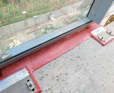
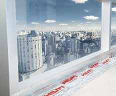
The field installation of the perimeter fire barrier system follows the listing w.r.t width of the gap between floor edge and curtain wall
Conclusion
It is important to have the ‘Fire Barrier System’ appropriately designed, installed, inspected, documented and maintained for serving its intended use. The system shall bear the design ‘Listing’ and ‘approval’ label and conform to the construction type, joint gap and fire, smoke and movement rating requirements of each separate assembly. It is the responsibility of the product manufacturer/supplier to provide a formal submittal consisting of system design listing or test certifications, including illustrations, from an accredited testing laboratory as per referenced standards that are applicable to each system configuration.
Adherence to code requirements ensures safety and peace of mind for the builders, contractors, architects, inspectors and occupants. In addition, it helps the fire fighters to carry out firefighting and rescue operations thereby enable to save lives and protect assets.
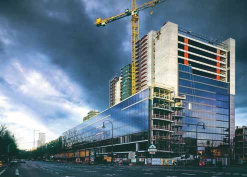
It is important to have the ‘Fire Barrier System’ appropriately designed, installed, inspected, documented and maintained for serving its intended use ARAVIND CHAKRAVARTHY V
Hilti (India) Pvt. Ltd.

ABOUT THE AUTHOR
Aravind Chakravarthy V is a Polymer Engineer having 15 years of experience in the field of product safety certification, inspection, testing and training as per UL, ASTM, ISO & IEC standards for materials used in electro-technical equipment and the built environment. In his previous stint with UL India Pvt. Ltd, he was leading the Techno-commercial activities in developing the testing and certification business for wire and cable, performance materials and had conducted several ‘Fire and Life Safety’ Inspections for various types of buildings including hotels, hospitals, malls, commercial complexes and educational institutions in India and the Middle East region. Since 2019, he is working as Head - Codes and Approvals for the Fire protection division in Hilti (India) Pvt. Ltd.

Energy efficiency is a key area of focus for architects looking for ways to ‘build greener’ without compromising building aesthetics, and it’s no surprise that vertical greenery systems have become a growing trend in increasingly dense urban environments.
Vertical greenery systems, also known as green walls, living walls or vertical gardens, are vertically built structures intentionally covered by vegetation, typically including a growth medium such as soil, substitute substrate, or hydroculture felt. They differ from ‘green façades’ in that they have the growth medium supported on the vertical face of the wall, whereas green façades have the growth medium located at the base. This allows living walls to contain more plant species than green façades, which are limited to climbing types.
Aside from the aesthetic value that green walls provide for buildings and urban centres, they’ve been shown to have environmental benefits by maximising CO2 absorption and oxygen production without sacrificing valuable ground space. They can function as an effective form of shading in warmer climates, cooling down building interiors by lowering the temperature of the exterior surface, and can extend the lifetime of façades by protecting them from UV radiation. In temperate climates, retrofitted green walls have been shown to reduce heat loss from buildings by over 30%.1
Acoustically, green walls have been shown to absorb more sound than traditional façades, resulting in increased focus and attention of occupants and reductions in stress levels, in addition to wellness promoted through biophilia and improvements in air quality.2
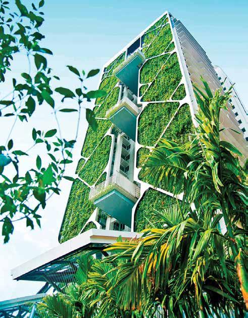
Figure 1 - Vertical Greenery System - Tree House, Singapore (Source: CDL)
Fire Safety Implications The concern with these systems is that they can present a means for fire spread along the external envelope of the building. As they are an emerging technology, there are few standards available on the fire protection of greenery systems, with guidance largely limited to green roofs, e.g. ANSI/SPRI VF1, External Fire Design Standard for Vegetative Roofs, and IBC Section 1507.16, Vegetative Roofs, Roof Gardens and Landscaped Roofs. At the time of writing, it was observed that no standards have been developed within the region for vertical greenery
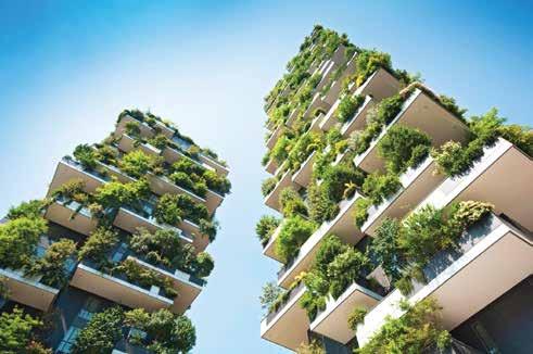
Figure 2 - Vertical Forest, Milan (Source: WSP NZ)
systems, which are therefore governed by the following statutory guidance documents: • The UAE Fire and Life Safety Code of Practice prescribes that, other than natural stones and concrete, only materials tested and listed with
Civil Defence and complying with specific flammability requirements are permitted on the exterior walls of a building. • The Saudi Building Code (SBC) permits limited-combustible materials on building façades.
However, they are limited to 12 m in height above grade and need to satisfy NFPA 268 ignitability testing.
This is expected to be further restricted in future revisions given recent updates to the International
Building Code (IBC), upon which SBC is based. • Qatar fire codes refer to British
Standards BS 476 Parts 6 and 7 (Fire Propagation Test and Surface
Spread of Flame Test), requiring a fire propagation index of no more than 4.0, and a flame spread of less than 25 mm after 10 minutes. Given that plant material is combustible and unable to pass these tests in its organic form, vertical greenery systems are generally not permitted by prescriptive fire code guidance, and for these systems to be incorporated into a building’s design; an alternative method of achieving compliance is necessary.
Routes to Compliance The intent of building regulations with regards to fire safety is to mitigate risks to a reasonable level, and traditionally such building codes have been prescriptive in nature. However, as prescriptive guidance cannot adequately address emerging technologies, following prescriptive guidance can result in design constraints that are not always appropriate to the specific building being considered. This is particularly evident with larger, more complex developments, where prescriptive compliance is generally not practical in all aspects of the design.
For this reason, the aforementioned codes do not prohibit methods or materials not specifically prescribed within the code, i.e. alternative designs are permitted, provided the alternative design complies with the intent of the provisions of the code, and that the design is, for the purpose intended, not less than the equivalent of that prescribed. Where an alternative design is proposed; a performance-based, or fire engineering approach is required to demonstrate that the design is functionally compliant with code requirements, which typically indicates one or more of the following analyses: • Qualitative analysis: a nonnumerical examination of the design using experience, knowledge, and engineering judgement alone. • Deterministic analysis: a quantitative assessment that calculates fire conditions and other parameters in absolute terms, often with the use

• of computer-based tools such as computational fluid dynamics (CFD) modelling software. • Probabilistic analysis: a quantitative approach that assesses the probability of fire events or outcomes.
Typically, qualitative analysis alone will only be sufficient for relatively simple deviations to prescriptive guidance, where the acceptability of an alternative design approach is so obvious that it can be demonstrated by a non-quantitative argument alone. For more complex problems, unless the level of risk is already sufficiently low or mitigated by sufficient conservatism, quantitative analysis will be necessary to assess the adequacy of the alternative design.3
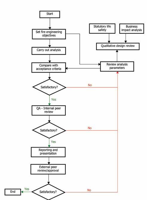
Guidance documents such as the International Fire Engineering Guidelines (IFEG), Society of Fire Protection Engineers (SFPE) guide to performance-based design, and BS 7974 Application of fire safety engineering principles to the design of buildings – Code of practice, each provide frameworks on how to develop appropriate performancebased design solutions, the latter of which is illustrated in Figure 4.
For a vertical greenery system to be incorporated in a buildings’ design, it would need to be demonstrated (using one or more of the above analyses) that the risk of ignition of the system is reasonably low, and if ignition were to occur, fire spread along the façade would be restricted such that the occupants of the building can safely evacuate, and firefighters can deploy operations within a reasonable timeframe and safely extinguish the fire.
Design Considerations The primary indicator of risk of ignition in greenery systems is moisture content of the plant material. Research studies of three common plant species used in green wall and roof systems, indicated that each species, when subject to flame impingement from a pilot source, would not ignite provided the moisture content was above a threshold value for that particular species. Where the species was allowed to dry and the moisture content dropped below this threshold, the risk of ignition increased significantly. The drying times necessary for this to occur were 4, 46, and 38 days for the respective species, however these times could potentially be reduced by summer temperatures within the region.4
The research highlights the importance of proper plant species selection, with a preference for those with lower moisture content thresholds for ignition, as well as proper maintenance and irrigation regimes to ensure that the moisture content is kept sufficiently high relative to these thresholds. The irrigation systems would likely need
