14 minute read
Solutions to Make the World a Greener Place
FAÇADE ACCESS
All About Façade Access
Advertisement
Mohamed Merchant
Associate Director, TÜV SÜD Dunbar Boardman
About the Author:
Mohamed Merchant is an Associate Director at TÜV SÜD Dunbar Boardman, Europe’s leading elevator, escalator and access consultancy. Operating throughout Europe, the Middle East and India, TÜV SÜD Dunbar Boardman is part of TÜV SÜD, one of the world’s leading technical service providers, which has more than 24,000 employees located across over 1,000 locations. He has 20 years’ experience in mechanical engineering, including 19 years in the façade access industry. During this time, he has designed and delivered façade access strategies and systems for major developments within the UK, Europe and the Middle East, including high-rise residential and commercial office developments, retail centres, refurbishment projects, hotels, hospitals and historic buildings.
IMPORTANCE OF FAÇADE ACCESS
Architecture is constantly evolving with increasingly challenging building envelopes and maintainability is one of the key aspects when detailing the iconic façade. Practical, economical and effective maintenance of the façade is a prime concern in the overall design concept.
The development of a façade access solution is a long-term process and the building maintenance strategy will be in place for the life of the building. Façade cleaning and maintenance has also evolved, using bespoke systems blended within the tight operating space whilst meeting the everincreasing demand for replacing façade panels and plant components during the service life of the development.
Façade access is highly specialised and niche industry with very limited expertise on global scale and sector-wide experience within the construction industry.

Façade access is a highly specialised and niche industry DESIGN IMPLEMENTATION OF FAÇADE ACCESS SYSTEMS
Façade maintenance varies from regular cleaning of the glazing to significant replacement of failed panels. Once the options to avoid working at height, set out in the working at height hierarchy, have been exhausted, then façade access equipment, whether it is temporary or permanently installed on the building can be employed to achieve the required access. Operatives are exposed to the hazard of falling from height. This may happen when:
Safe access points in and around the FAE are not considered
Structural failure
Accidental tipping when the FAE snags on building façade
Exposed to the hazard while installing the system or while maintaining the system
Risk to general public in the vicinity of the FAE i.e. hazard of being struck by falling objects
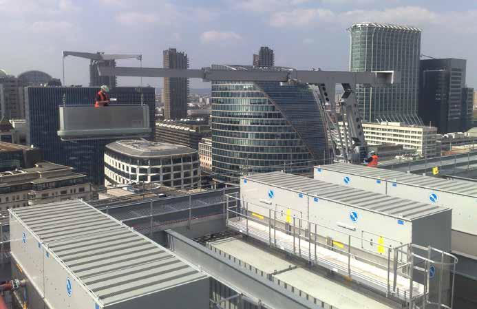
The options for access are from the top down or bottom up. For low rise developments, up to 40m, Mobile Aerial Work platforms can be employed providing sufficient consideration is given to the landscaping to allow the machines area to work. Above this level top down building maintenance units (BMUs) come into their own.
At one time the roof was the preserve of MEP and the space required for a BMU was easily found at the edge of the roof, this allowed smaller lighter machines to be employed for access to the façades. As roofs evolved to become either the 5 th elevation or communal spaces with terraces, gardens and penthouses the competition for floor area meant that the traditional areas available became more constrained. This frequently led to a longer reach single BMU located on the core of the building leaving the perimeters free and unobstructed. These machines are larger and heavier but with the load borne by the strongest part of the building.
Regardless of the position of the BMU on the roof building, coverage can be a particular problem on buildings with complex façades. Twisting facades create problems of their own and sky bridges create a similar dead area as balconies. Counterweighted cradles for underhanging areas, separate systems for inset areas will add weight and cost to the machines or additional systems to the building. The challenges caused by complicated facades become magnified when adding glass replacement into the equation.
GLASS REPLACEMENT
An increasingly common option is to use the BMU to replace the glazing or other sections of the façade with the facility of an auxiliary hoist in addition to the cradle for the operatives. (Note: Total suspended load on glass lifting winch is limited to 1 ton as per BS EN 1808).
The reality is that once glass has been installed it will generally last beyond the lifetime of the building unless subjected to an external force. After practical completion of a building the breaking of individual panes of glass is relatively rare with instances of warranty failure being a more likely reason for panels to be replaced.
In some instances, glazing panels are replaced internally (due to internal beading or within balcony zones) however the panel is delivered externally due to restricted lift or lobby sizes. Clear operating zone will be required for transporting glazing manipulator within the building to the location where replacement is required.
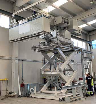
Working BMU scissor lift


BMU glass fitting
FAÇADE LOADINGS
In general operation the cradle of the BMU will lightly touch the façade unless an external force is placed upon it. In normal operation the only external force will be the wind. The use of the cradle is limited by the wind speed. In general, the equipment shouldn’t be used if the wind speed is likely to exceed 12m/s (25 mph) this equates to a Force 6 (strong breeze) on the Beaufort scale.
On the weather side of the building, suspended platform will be held against the façade and the wind loading will be the same. On the lee side, the cradle is shielded from the wind. The building sides have the most risk, but the suspended platform is presented end on with its smallest profile. The lee corners of the building can be the worse points as a rotor. Solar shading fins, louvers and brise soleil can also pose problems with the loads on them being localised
STRUCTURAL LOADING
The effects of ‘in-service’ and ‘fall arrest’ (overload / overspeed / accidental) loads imposed upon the

Equipment connections to the structure should be welded, bolted, or cast in place
building structure from the operation and storage of façade access equipment are significant and should be coordinated with the structural engineers throughout the design process.
Load paths through the structure should be accounted for when evaluating the reactions of the façade access systems in all its operational and stored positions when fully loaded.
Equipment connections to the structure should be welded, bolted, or cast in place. The attachment method should be defined during early design stages so that correct provision to periodic inspect of the fixings are integrated within the roof finish.
Safety and stability factors are determined by local codes and industry standards and should be incorporated in the design calculations of the access equipment and building structure. This is particularly important for steel structures due to the possibility of beam torsion and the necessity of additional reinforcing steel in those areas. BS EN 1808 recommends the BMU specific factors be applied to the design loads for the superstructure.
ACOUSTICS
Flanking Sound Transmission between Adjacent Dwelling Units through the Façade

Harout Taghilian
Senior Acoustic Engineer, Ramboll Middle East
About the Author:
Harout Taghilian holds a Bachelor of Science in Physics and a Diploma in Acoustics and Noise Control. He started his career in Noise and Vibration Engineering in 2013 in Lebanon. In 2018, he moved to Dubai to work at Ramboll. After obtaining his Diploma with distinction and having more than five years of work experience, he was professionally registered with the British Engineering Council as an Incorporated Engineer through the Institute of Acoustics. Throughout his career, Harout worked on numerous projects in Lebanon and throughout the Middle East region providing solutions for different kinds of acoustic problems. His expertise covers a wide range of building acoustics and environmental noise control projects. Harout is currently working as a senior acoustic engineer at Ramboll Middle East, specialising in Noise and Vibration Control Engineering.
As the world’s population increases, multifamily dwellings must be constructed to accommodate higher densities. Due to the increasing world population, many people are living in multistory apartment buildings. Noise from adjacent neighbors can adversely affect the comfort of the residents. Accordingly, it is important to control noise transmission between dwelling units by specifying suitable constructions.
Different countries have different regulations/ minimum code standards when it comes to sound insulation between multifamily dwellings. Walls and floors should be designed so that adequate airborne and impact sound insulation is provided.
The major reasons for noise complaints in multifamily dwellings are due to lightweight building structure, poor acoustical design, and poor quality of workmanship.
It is a good design practice to select wall systems that are reliable and easy to construct to reduce issues during construction. Achieving adequate sound insulation between dwelling does not just depend on the selection of the wall type but also the proper detailing and installation of the partition.
The focus of this article will be on airborne sound transmission and specifically on flanking sound transmission through the façade junction.
Manufacturers and suppliers typically provide the sound insulation performance of their products as a laboratory R w /STC value. It is important to understand the difference between a laboratory tested partition (R w /STC value) and an on-site tested partition (D nT,w /ASTC value). When tested under controlled conditions in a laboratory, the partition is installed in an optimum way without typical flanking paths present. In reality, when a partition is installed on-site a reduction in acoustic performance can be expected due to flanking sound, penetrations (electrical outlets, mechanical services penetrations, etc.) and workmanship.
Flanking is a description of the sound that passes around a sound insulating wall or floor by indirect paths (rather than directly through an intervening partition), and it can drastically reduce the on-site level of the sound insulation. Examples of common flanking paths include:
Ceilings
Mullions
Transoms
Raised floor access
Penetrations
It is not economical to select acoustically high performing partitions and later inadvertently short circuit their efficiency by having flanking sound transmission. Accordingly, it is important that different design disciplines are coordinated during the early stages of the design and pay close attention to proper detailing to avoid any retrofitting and noise complaints when the building is occupied.
One of the common overlooked flanking sound transmission between adjacent dwellings is via the connection between the internal partition and the exterior façade.
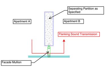
Interior partitions separating different dwelling units will eventually meet an exterior wall. Ideally, the wall should join the exterior façade with solid construction so that the acoustical performance is maintained. However, we often see that this is not the case where the internal walls intersect at a façade mullion. The issue with such an interface is that the exterior mullions are constructed from thin, hollow, aluminum extrusions which have very little mass and are therefore a “weak” acoustic link. This is shown in Figure 1.

Figure 1: Flanking sound transmission through the façade - Typical example
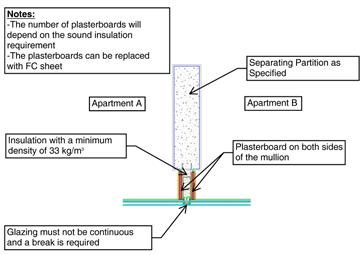
Figure 2: Typical details for treating flanking via the mullion

To reduce flanking sound transmission, the mullion should be covered with additional layers of plasterboard, FC sheet, or heavy metal.
Figure 2 shows a typical detail for such a treatment. The number of plasterboard layers on each side of the mullion will depend on the R w /STC requirement of the dividing wall. It is important that the glazing is not continuous across the wall line between spaces and that a break is provided.
Another issue is when the internal partitions do not align with the façade mullions. This is not ideal from an acoustic point of view and additional measures to be provided to reduce flanking sound transmission. This has to be looked at on a case by case basis in coordination with a professional acoustical consultant.
In addition to horizontal flanking sound transmission, vertical flanking sound transmission should also be controlled. Usually, in high-rise constructions, the exterior curtain walls are supported from the edge of the floor slab, and because of the gap left between the floor slab and the external façade, there is flanking sound transmission. Again, this problem can be avoided by proper design and coordination between the façade designer and the acoustical consultant. In a recent project, we conducted field sound insulation tests to investigate the sound insulation of a partition separating adjacent dwelling units with and without treating the flanking sound transmission through the façade mullion. The tests were carried out between the same rooms to check the improvement of the façade mullion treatment.
After covering the façade mullion with additional layers of plasterboard and insulation, the airborne sound insulation increased from D ntw (C,C tr )=40 (-2;-5) dB (without treating the mullion) to D ntw (C,C tr )=51 (-2;-8) dB. If we look at D nt,w +C tr value (which the Dubai Green Building Regulations requirement is based on), we can see that the performance increased from 35 dB (40-5) to 43 dB (51-8). But what does this 8 dB improvement mean in terms of subjective perception?
The subjective response for variation of sound pressure level has been investigated for a group of people and the results are summarised in the table below.
Looking at Table 1 we can see that by only treating the façade mullion, the perceived loudness of the noise is almost halved.
Change in Sound Level (dB)
3
5
10
20 Change in Apparent Loudness
Just perceptible
Clearly noticeable
Half or twice as loud
Much quieter or louder
Table 1: Subjective effect of changes in sound pressure level
CONCLUSION
People are becoming more and more demanding for acoustic privacy in their homes especially when a person is purchasing a permanent home rather than renting an apartment.
To minimise annoying disturbances caused by noise transmission between dwelling units or between noise-sensitive areas, architects and designers must have a general knowledge of the principles of sound transmission and provide proper design to mitigate any noise issues. As seen from the test results discussed earlier, paying attention to a small detailing increased the acoustic privacy significantly.
We are living in times where designers must pay adequate attention to acoustical comfort. During the design stage, there are several options for controlling noise transmission and some options may be rejected due to the requirements of different disciplines. It is during this stage where other options can be discussed, designed, and implemented on-site.
It should be noted that in addition to noise transmission between dwelling, attention shall be paid to intrusive noise (aircraft and road traffic, recreational noise, etc.), MEP noise and vibration, and impact noise which are other sources of noise complaints in multi-storey apartment buildings.
An ounce of prevention is worth a pound of cure. Correcting a noise problem after construction usually costs much more than preventing one. The real costs don’t only include the material cost for the retrofitting but also loss of reputation, public confidence, and the time required for coordinating and retrofitting (especially if the rooms are already occupied by tenants).
TERMINOLOGY USED IN THIS ARTICLE CAN BE FOUND BELOW
Apparent Sound Transmission Class (ASTC):
Apparent sound insulation of a partition separating two spaces. All sound transmission, including any flanking sound transmission, is ascribed to the partition. The actual transmission loss of the partition (measured in an acoustic laboratory) will usually be higher than the apparent transmission loss.
Sound Reduction Index (R) And Spectrum Adaption
Term C tr : The sound reduction index (or transmission loss) of a building element is a measure of the loss of sound through the material, i.e. its attenuation properties. It is a property of the component, unlike the sound level difference which is affected by the common area between the rooms and the acoustic of the receiving room. The weighted sound reduction index, R w , is a single figure description of the sound reduction index which is defined in BS EN ISO 717-1: 2013. The R w is calculated from measurements in an acoustic laboratory. Sound insulation ratings derived from the site (which are invariably lower than the laboratory figures) are referred to as the R’w ratings.
Ctr is a spectrum adaption term to account for lowfrequency noise (C tr ).
Sound Level Difference (D): The sound insulation between two spaces may be expressed by the sound level difference needed between them. A single figure descriptor, the weighted sound level difference, D w , is sometimes used (see BS EN ISO 717-1). This parameter is not adjusted to reference conditions. The standardised level difference, D nT , is a measure of the difference in sound level between two rooms, in a given frequency band, where the reverberation time in the receiving room has been normalised to 0.5 s. This parameter measures all transmission paths, including flanking paths. The weighted standardised level difference, D nT,w , is a measure of the difference in sound level between two rooms, which characterises a range of frequencies and is normalised to a reference reverberation time.
Sound Transmission Class (STC): The sound transmission class is a widely used American rating for a building partition’s isolation value based on laboratory measurement. It is a single number rating calculated in accordance with Classification ASTM E413 using values of sound transmission loss. It provides an estimate of the performance of a partition in certain common sound insulation problems.


