


Discover the advantages www.belimo.com


Belimo’s gas monitors are factory calibrated and measure single or dual gas combinations to help maintain adequate ventilation. The monitors can be used as a standalone system or integrated into a building automation system using BACnet MS/TP.


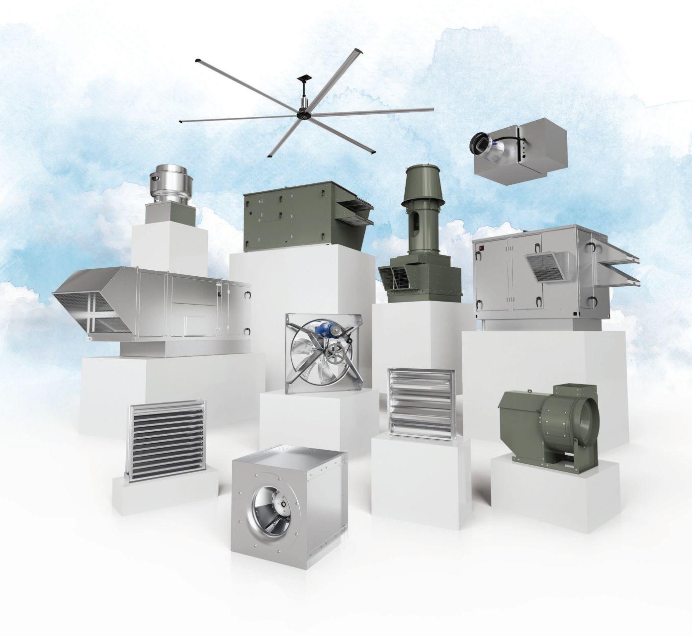
If you only think of Greenheck as a fan company, think again. We engineer and manufacture the industry’s most comprehensive line of air movement, control, conditioning, and distribution products for commercial, industrial, and institutional buildings. Our energy-efficient products keep occupants comfortable, productive, and safe while supporting sustainability. Let us help with your next project.


5 | What do world travel and engineering have in common?
22 | Know specific, unique specifications of generators in mission critical facilities


Read on for more. See page 7.

ON THE COVER:

How does a 40 Under 40 winner balance work, innovation, community and family?

The 2024 40 Under 40 winners represent some of the top talent in the building community. Courtesy: Consulting-Specifying Engineer


How travel makes commercial buildings better
Electrical engineers should consider many factors when selecting generators and generator systems for mission critical facilities
28 | How to make generator fuel type selection in four steps
When selecting a generator, one of the first and most important decisions is which fuel type to choose
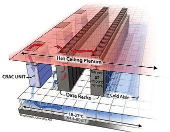
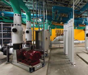
34 | Using fluid technology to address colling limitations in data centers
Increased focus on unique cooling solutions for data centers address the limitations of traditional systems
40 | How to specify emergency lighting controls under new standards
Understand how to approach revised UL listing requirements when specifying emergency lighting controls
44 | Learn to specify pressureregulating devices in waterbased fire protection
Understand why pressure-regulating devices are required to maintain safe system working pressures in fire protection systems
53 | Trends and challenges unique to modern data center design
In this roundtable, experts answer common questions about the challenges and considerations of designing data centers in our highly connected world


Optimizing the harmonic load on your systems increases their lifespan and decreases downtime.


HPS has the portfolio of power quality solutions and the engineering expertise to deliver the efficiency, reliability, and longevity to help ensure that your operations keep flowing smoothly.


AMARA ROZGUS, Editor-in-Chief/Content Strategy Leader ARozgus@CFEMedia.com
CHRIS VAVRA, Web Content Manager CVavra@CFEMedia.com
ANNA STEINGRUBER, Associate Editor ASteingruber@CFEMedia.com
AMANDA PELLICCIONE, Director of Research APelliccione@CFEMedia.com
MICHAEL SMITH, Creative Director MSmith@CFEmedia.com
DARREN BRUCE, PE, LEED AP BD+C, Director of Strategic Planning, Mid-Atlantic Region, NV5, Arlington, Va.
MICHAEL CHOW, PE, CEM, CXA, LEED AP BD+C, Principal, Metro CD Engineering LLC, Columbus, Ohio
TOM DIVINE, PE, Senior Electrical Engineer, Johnston, LLC, Houston
CORY DUGGIN, PE, LEED AP BD+C, BEMP, Energy Modeling Wizard, TLC Engineering Solutions, Brentwood, Tenn.
ROBERT J. GARRA JR., PE, CDT, Vice President, Electrical Engineer, CannonDesign, Grand Island, N.Y.
JASON GERKE, PE, LEED AP BD+C, CXA, Mechanical Engineer, GRAEF, Milwaukee
JOSHUA D. GREENE, PE, Associate Principal, Simpson Gumpertz & Heger, Waltham, Mass.
RAYMOND GRILL, PE, FSFPE, LEED AP, Principal, Ray Grill Consulting, PLLC, Clifton, Va.
DANNA JENSEN, PE, LEED AP BD+C, Principal, Certus, Carrollton, Texas
WILLIAM KOFFEL, PE, FSFPE, President, Koffel Associates Inc., Columbia, Md.
WILLIAM KOSIK, PE, CEM, LEGACY LEED AP BD+C, Lead Senior Mechanical Engineer, kW Mission Critical Engineering, Milwaukee
KENNETH KUTSMEDA, PE, LEED AP, Engineering Manager, Jacobs, Philadelphia
DAVID LOWREY, Chief Fire Marshal, Boulder (Colo.) Fire Rescue
JASON MAJERUS, PE, CEM, LEED AP, Principal, DLR Group, Cleveland
JUSTIN MILNE, PE, PMP, Senior Engineer, Southcentral Region, Jensen Hughes, Allen, Texas
GREGORY QUINN, PE, NCEES, LEED AP, Principal, Health Care Market Leader, Affiliated Engineers Inc., Madison, Wis.
BRIAN A. RENER, PE, LEED AP, Principal, Electrical Discipline Leader, SmithGroup, Chicago
CRAIG ROBERTS, CEM, Account Executive, National Technical Services, McKinstry, Powell, Tenn.
SUNONDO ROY, PE, LEED AP, Director, Design Group, Romeoville, Ill.
JONATHAN SAJDAK, PE, Senior Associate/Fire Protection Engineer, Page, Houston
RANDY SCHRECENGOST, PE, CEM, Austin Operations Group Manager/Senior Mechanical Engineer, Stanley Consultants, Austin, Texas
MATT SHORT, PE, Project Manager/Mechanical Engineer, Smith Seckman Reid, Houston
MARIO VECCHIARELLO, PE, CEM, GBE, Senior Vice President, CDM Smith Inc., Boston
RICHARD VEDVIK, PE, Senior Electrical Engineer and Acoustics Engineer, IMEG Corp., Rock Island, Ill.
TOBY WHITE, PE, LEED AP, Associate, Boston Fire & Life Safety Leader, Arup, Boston
APRIL WOODS, PE, LEED AP BD+C, Vice President, WSP USA, Orlando, Fla.
JOHN YOON, PE, LEED AP ID+C, Lead Electrical Engineer, McGuire Engineers Inc., Chicago
How travel makes commercial buildings work better
If you know me, you know I can talk about travel all day — upcoming trips, packing recommendations and funny connection hiccups. I can also share what I’ve learned from visiting buildings around the world.
Traveling is a great way to expand your mind and experience new things. But for people who work in mechanical, electrical, plumbing (MEP) and fire protection engineering, it can be even more meaningful. When you get to see how buildings are designed and built in different parts of the world, it can really change how you think about your own work.
In Canada, where it’s freezing, they know all about heating and keeping buildings insulated. After experiencing these different environments, I’ve learned to think about all kinds of solutions when designing systems for commercial buildings.


Amara Rozgus, Editor-in-Chief
I’ve traveled to all seven continents and seen all kinds of buildings, from supertall skyscrapers to small research stations in the coldest places on Earth. Here’s why I think traveling helps improve engineering.
One of the best things is that you get to learn from other cultures. In Europe, for example, you often see old buildings that have been updated with modern MEP systems. This shows that you can keep a building’s character while still making it work. In Asia, places like Shanghai are so crowded that they’ve had to come up with some clever ways to save space and energy. When you see these solutions in person, it makes it easier to come up with smart ideas for your own projects.
Traveling to different places lets you see what challenges they face and how they solve them. In Kenya, which straddles the equator, they have ingenious ways to save energy and water.
Visiting famous buildings can give you tons of new ideas. On my travel wish list is a visit the Burj Khalifa in Dubai — the tallest building in the world — where you see how they handle plumbing and fire protection at crazy heights. Or in Melbourne, Australia, there are healthy commercial indoor workplaces. Seeing things like this up close can really get your creative juices flowing.
Traveling also lets you meet people from different countries who do the same work. When you go to conferences, you can talk with others and share what you know. Building these connections helps you stay on top of new trends and technologies. It’s a great way to make sure you’re not stuck doing things ineffectively.
If you work in MEP engineering, traveling can be a game-changer. This mix of new ideas and fresh perspectives makes commercial buildings more efficient and innovative, which is important as we move into a future where we need to think about things like energy use and climate change. In all, travel is a great way to make sure you’re always learning and improving. cse


Look familiar?
If your power infrastructure includes renewables, battery storage and/or EV charging, a microgrid may be the missing piece you need to bring it all together.
At the heart of such a system is an intelligent microgrid controller that maintains overall system stability and dynamically manages
generating assets and loads to optimize power flow based on user-defined goals.
Eaton’s Power Xpert microgrid solutions provide reliable power that delivers operational resilience, minimizes carbon emissions and reduces energy costs.
To learn more go to: Eaton.com/microgrid


Each year, Eaton has the pleasure of recognizing the most talented young individuals across the engineering community as the title sponsor of Consulting-Specifying Engineer’s 40 Under 40 Awards. Your dedication, expertise, and commitment to the engineering industry have truly set you apart.
As we celebrate your achievement, we want to recognize the ever-growing complexity of engineering challenges you have so successfully navigated. The construction and engineering landscape is evolving rapidly, with new technologies and sustainability practices, and project complexities growing every day.
As this year’s winners, you have shown you are up for the challenge to stay ahead of the curve and equip yourselves with the knowledge and tools needed to thrive in this dynamic environment.
Eaton shares your passion for continuous learning and growth and is proud to see all you have accomplished. To support our commitment for continuous learning and growth, we are actively involved in designing educational resources to enable you to solve the next iteration of engineering challenges.
Once again, on behalf of all of us at Eaton, congratulations on this remarkable achievement! Your passion, leadership, and innovative spirit inspire us all. And we look forward to witnessing your continued success and contributions to our industry.


Chris M. Finen, P.E. Manager, National Application Engineers


Liz Alford .
Lauren Alger . . . . .
.10
.10
Yevgeniya (Jane) Baikadanova .10
Jodi Balido . . .
Victor Bonachea .
Zac Buckmiller
Jamison Caldwell . . . .
John Constantinide . . .
Devanshi Dadia
Michelle DeCarlo .
Katelyn DePenning . .
Tony Dupsky
Jeffrey Engelstad
Alyse M . Falconer
Michelle Fennell
Paul Foerth
Lauren Foster
Christoph Gisel
Robin Graves . . . .
Todd Green .
Kenneth Griffin
Morgan Heldstab
Katelyn Jones
Hunter Koch
Tzu-Hao Kuo
Christopher Lau . . . . . . .
Matthew J . Lick
Amar Maniar
Ali Moussawi
Liam Murphy
Cole Parkinson
Alex Quast
Brandi Sauter
Mariah Seaboldt
Greg Sherman
Alex Sibila
Johnathan Stewart
Lilly Vang
Katie Wholey
Mary Wurst
.10
.11
.11
. 11
.11
.12
.12
. .12
.12
.13
.13
.13
.13
.14
.14
.14
.14
.15
. .15
.15
.15
.16
.16
.16
16
.17
.17
.17
.17
.18
.18
.18
.18
.19
19
.19
.19


THow does a 40 Under 40 winner balance work, innovation, community and family? Read on for more
he 2024 40 Under 40 program celebrates engineers and building professionals who have excelled in various disciplines within engineering and construction, showcasing innovation, leadership, mentorship, sustainability and community involvement. Despite their diverse backgrounds, these individuals share common values and have made significant contributions to their fields and to society. Beyond their professional accomplishments, the winners are dedicated to giving back to their communities. Collaboration is another common thread among this year’s 40 Under 40 winners, who excel at building strong relationships with clients and project stakeholders. And despite their demanding careers, these professionals lead fulfilling personal lives.


Mechanical Engineer, CMTA; BS, Engineering, University of Kentucky


lford joined CMTA in 2015 as an engineering co-op student and became a full-time employee upon graduating in 2017. Since then, Alford has worked with Jefferson County Public Schools and has been an integral part of the HVAC renovations design team for seven existing high schools and two existing middle schools, totaling over $200 million in project construction costs. Additionally, she has designed two high-performance, new construction educational facilities with geothermal HVAC systems for the district. She recently led building information modeling coordination efforts for a new five-story patient tower addition to an existing hospital, as well as for a new 3,750-ton central energy plant serving an existing hospital. Alford is passionate about finding unique design solutions and learning new ways to optimize central plants. In 2019, she began investing in CMTA’s co-op program by conducting employment interviews and has attended numerous university recruiting events to develop the next generation of young engineers. Alford has spoken to several Society of Women Engineers (SWE) chapters about high-performance mechanical systems and participated at the SWE conference in Los Angeles. She is passionate about reaching women in the engineering field and educating them about opportunities in the built environment. Alford is committed to both engaging future generations of engineers and working to provide an occupant-focused built environment that serves the needs of her clients. Outside of the office, Alford enjoys playing on adult league soccer indoor teams or playing beer league softball with her wife’s law firm.
Principal/Owner, IPQ LLC; MS, Systems Engineering, George Washington University
Director of Sustainable Design, STV; BS, Civil and Infrastructure Engineering, George Mason University


The foundation of Alger’s career is based in civil engineering, as she was inspired to follow in her father’s footsteps. Since graduation, she embarked on a path to redefine sustainable design practices and has worked on many projects that incorporated green design elements. Determined to have a more significant impact on sustainable practices in the early planning and design stages, so Alger earned her professional engineering license and accreditation as an Envision Sustainability Professional. In 2022, Alger joined STV in the newly established position of sustainability manager where she embarked on building the firm’s national sustainability practice and quantifying sustainable design efforts across projects, charting a course for future action while tackling the firm's carbon footprint head-on. Alger led the multidisciplinary team that developed STV’s new Embodied Carbon Action Plan, acting as the first step in fulfilling the firm’s Structural Engineers 2050 Commitment for colleagues to reduce embodied carbon, track data and analyze findings through STV’s Carbon Dashboard. She is also the chair of the American Society of Civil Engineers Infrastructure 2050 group. Outside of her work, Alger is a student research mentor for Columbia University’s Center for Buildings, Infrastructure and Public Space. She also volunteers with the Salvadori Center, an esteemed organization that partners with schools to provide math, science and arts programs to K-12 students. In her downtime, she enjoys hiking at national parks, rock climbing and attending concerts when she is at home in New York City.


fter moving to the United States in 2008 from her home country of Kazakhstan, Baikadanova worked several odd jobs to put herself through graduate school. Most notably, she worked as a receptionist for a prominent engineering firm in Virginia, confident that her dedication to the industry would land her an engineering role. In 2011, her confidence was rewarded with her first job as a junior engineer. Since then, she has worked as a senior electrical engineer and project manager, where she has designed and calculated lighting and power systems for health care facilities, government, commercial facilities and more. As a senior electrical engineer, Baikadanova led a team of junior engineers and drafters to prepare schematic and detailed construction documents. She also has contributed to Consulting-Specifying Engineer as an author, webcast host and podcast guest. She credits her time in the service industry for her strong people skills that make her stand out as an engineer. In 2023, she made the daring switch to entrepreneurship and opened her own firm, which she hopes will show her 3-year-old son that with hard work and perseverance, anything is possible. Her current and past colleagues highlight not only her magnetic personality and work ethic, but also the resiliency in her story and how it can help inspire others. Baikadanova herself hopes to do the same in the day-to-day of her career. Outside of work, Baikadanova enjoys riding motorcycles and dirt bikes, hosting cookouts and training her Swiss Shepard on dog agility courses
Global Fire Safety Manager, The LEGO Group; BS, Architectural Engineering, Illinois Institute of Technology

Balido has made strides in fire safety management within The LEGO Group since joining as global fire safety manager in 2023. His prior engineering experience includes both design and owner representation roles. His proactive approach to risk management and his can-do mindset have earned him respect among colleagues and stakeholders in the different countries where The LEGO Group operates. He participates in risk inspections, providing recommendations to enhance operational resilience across multiple sites. He is involved in the design of large-scale factory expansions, coordinating and developing comprehensive fire safety strategies. Balido also holds a Graduate Certificate in Fire Protection Engineering from University of Maryland. He has written articles on fire protection and risk management topics. Balido was a former Toastmasters Club President in 2020, and hosted the Winter Leadership Institute Seminar in Richmond, Virginia. In 2023, Balido volunteered as a panelist for the Midwest Filipino American Summit, a networking and development event for Filipino American students at various Midwest U.S. universities. He also serves as one of the voting principal members on the Building Service and Fire Protection Equipment committee for NFPA 101 and NFPA 5000. Beyond his professional endeavors, Balido remains committed to his family and community. As a loving husband and father of three, he prioritizes his role at home while also engaging in activities such as running marathons, breakdancing, coaching basketball and supporting his children's interests. He also self-published a fantasy novel to Amazon in 2018 under a pseudonym.
Product Strategy Director, ASCO Power/Schneider Electric; MS, Engineering Management, New Jersey Institute of Technology


Bonachea has been an integral part of ASCO Power Technologies, a brand within Schneider Electric, since 2011, joining during his senior year as an electrical engineering undergraduate student. Bonachea’s work focuses on power distribution and emergency power systems. During his time in offer marketing and product development, he has secured multiple patents, including methods and systems for autonomous redundant control, methods of predictive outage detection and systems for controlling a generator. These patents, along with his work on products like source isolation switches, load management solutions and engine start monitoring systems, demonstrate his commitment to making power continuity more accessible for all organizations. The innovations he has worked on have increased power reliability, resilience and sustainability. Outside of his work with ASCO, Bonachea contributes to his field as a voting technical member of NFPA. He is an IEEE Senior Member and involved with several IEEE 3005 Standards, demonstrating his expertise in electrical power management and control, generator paralleling and transfer switching. Bonachea has also contributed and delivered numerous articles and technical speaking events and is enthusiastic about sharing his knowledge with in-house teams, corporate divisions and the larger backup power community. Bonachea served as a volunteer firefighter in his New Jersey hometown for 15 years. Outside of work, he spends a lot of time on home automation projects. He is currently finishing his gaming room and deck, with the hopes of hosting barbecues and science-fiction movie nights.
Principal, Mechanical Engineer, SmithGroup; BS, Lafayette College
Kansas City MEPF Practice Leader, Garver; MBA, University of Arkansas


As Garver’s Kansas City Buildings Practice Lead, Buckmiller has dedicated his career to bringing to life the foundations of a strong community. From hospitals to sports parks, Buckmiller’s work as an architectural engineer is focused on designing the buildings that contribute to the Kansas City region’s rich architectural history. He has designed buildings across industries, including new health care centers, large corporate office spaces and over 6,800 multifamily apartments. A mechanical engineer by trade, Buckmiller’s expansive experience makes him a generalist in his field, with the ability to design many facility types. Garver has been present in the Kansas City area for years, and Buckmiller has been a lead on expanding the firm’s brand into new markets across the region. He offers clients a local expert and “one-stop shop” for structural, civil, mechanical, electrical, plumbing and fire protection engineering services. He has also led the charge to improve the Revit and BIM standards, as well as a consistent process to create documents for Garver’s Buildings Team. In addition to drawing standards and processes, Buckmiller has also created several engineering calculations that assist in project documentation and reduce project errors. Looking toward the future, he is working to integrate BIM and calculations to further provide a higher quality product while also maximizing technology. Outside of work, Buckmiller enjoys being as active and spends his time playing and coaching ice hockey.


aldwell is a distinguished mechanical engineer renowned for his contributions to decarbonization and high-performance building design. Based in Washington, D.C., he is a leading figure at SmithGroup, driving innovation and sustainability in engineering solutions. Caldwell’s journey began in central Maryland, where a high school engineering class ignited his passion for design. At Lafayette College, he pursued mechanical engineering while playing varsity lacrosse. After college, his focus shifted to high-performance building design and sustainability and he swiftly gained expertise in the mission critical field. Caldwell’s portfolio spans diverse sectors including higher education, science and technology, health care and cultural institutions. Notable projects include the Henry Ford Cancer Institute Brigitte Harris Cancer Pavilion and the Virginia Tech Innovation Campus. He also has contributed to campuswide carbon emission reduction planning, exemplified by his work at North Carolina State University. Caldwell also has worked on R&D initiatives, focusing on patentable concepts for increased building efficiency. He has served on SmithGroup's national engineering standards team. His passion for sustainability extends to several articles he has written with an emphasis on evidence-based operational decision-making and the potential of heat pumps in environmentally conscious design. Caldwell enjoys being outside with his family, opting for sailing, kayaking, biking or just chasing their German Shorthaired Pointer dog. Caldwell lives with his wife, who he met in high school, and their two young children.
Range Engineer, U.S. Space Force; MS, Environmental Resource Management, Florida Institute of Technology

Constantinide’s training and experience spans the sciences, engineering and leadership. In his role with the U.S. Space Force, he is the subject matter expert advising squadron and installation leadership on facility and infrastructure resolutions, leading engineering innovation projects for Space Launch Delta 45. He oversees work by energy managers on energy reduction and resilience for the Delta’s utility program supporting the world’s most active spaceport. His work has resulted in hundreds of thousands of dollars saved in process efficiencies and contract modifications. He also oversees pilot, innovation and resilience programs investing millions of dollars in facilities and infrastructure. Constantinide has contributed to the built environment knowledge base of the government and the industry through several publications. He also has been a guest lecturer at several universities and participated in podcasts, conferences and local seminars on topics ranging from how indoor air quality improves workforce health and resilience to environmental controls of space habitats and transport vessels. He is a director and regional chair of ASHRAE, chair of ASHRAE Technical Committee 9.13 Space and public sector co-chair and incoming vice chair of the Society of American Military Engineers Energy and Sustainability Community of Interest. Outside of work, Constantinide enjoys playing tennis with friends, hiking on natural parks and trails, prayer, meditation and reading on philosophy and theology.


Associate Energy Analysis Practice Lead, Atelier Ten; MSc in Sustainable Design, Carnegie Mellon University


adia has established herself as a leader in energy analysis and environmental design and is dedicated to advancing sustainable practices within a built environment. Dadia oversees a team of 14 energy analysts, shaping project assignments and framing energy analyses as an associate and energy analysis practice leader at Atelier Ten. Dadia has demonstrated versatility across various roles, including mentorship, supervision, technical leadership and project management. Her expertise spans diverse building typologies and climate zones, where she consults on energy analysis, existing building retrofits and decarbonization strategies. She employs her analytical prowess to advocate for informed investment decisions, as showcased in a recent project where an analysis led to significant cost and space savings through dynamic blinds implementation. Her contributions to developing calibrated energy models and testing efficiency measures have empowered institutions like K-12 schools, museums and hotels to formulate comprehensive decarbonization plans. Dadia contributes to the ASHRAE Sustainability and the LEED Energy and Atmosphere Technical Advisory Group. Dadia also remains very active in community service and has volunteered with organizations like Shrimad Rajchandra Love and Care. She has been involved in fundraising for COVID-19 relief to organizing environmental cleanup drives and aiding earthquake victims. Dadia enjoys exploring new restaurants and cooking with her husband. She is an avid hiker and enjoys exploring the world.
MEP Manager, McCown Gordon; BS, University of Kansas
Associate Partner, Jaros, Baum & Bolles; BS, Mechanical Engineering, Villanova University

As the first female partner at JB&B, DeCarlo has emerged as an indomitable leader in the New York real estate industry, blazing a path for countless women, leaving an indelible mark on the industry and inspiring generations to come. She wrote the firm’s parental leave policy in 2015, championing work-life balance and spearheaded a groundbreaking diversity, equity and inclusion resource. Her career arc encompasses many building types and market sectors, chief among them commercial office buildings, laboratories and transportation facilities. She has shone in projects emblematic of profound transformation, of dramatic shifts to the new. Recent projects include the new core and shell office design for 30 Hudson Yards, the commercial office redevelopment of the landmarked Moynihan Train Hall and the New Terminal One at John F. Kennedy International Airport. DeCarlo is very involved in the advancement of women in the industry. In 2018, she launched the JB&B Women’s Initiative, an in-house membership group whose mission is the empowerment of women, positioning them as leaders inside and outside the firm and promoting their retention through leadership and professional development. She also serves on the board of directors for the Commercial Real Estate for Women of New York. She recently completed four years of service on the ASHRAE New York Board of Governors, serving as chairperson of its Women in ASHRAE Committee. Yet for all her leadership roles, DeCarlo is perhaps most proud of one closer to home: She is the Girl Scout troop leader for her twin daughters’ troop.


ePenning is a pioneering force reshaping the sports and engineering realms through her innovative work and tireless advocacy for diversity and inclusion. Beginning her career at Henderson Engineers in 2011, she has showcased project management prowess in the retail sector before transitioning to specialize in sports venue design. DePenning’s notable projects include the groundbreaking KC Current’s Training Complex, the first-ever purpose-built facility for a U.S. women’s professional sports team. Her leadership extends to the upcoming CPKC Stadium, a $117 million venue that opened in March 2024 for the Kansas City Current, a National Women’s Soccer League team. DePenning also is dedicated to uplifting underrepresented groups. She co-founded UNITE, a resource group supporting LGBTQIA+ employees and allies and played a pivotal role in EMPOWER, advocating for gender equity and organizing impactful events like the "Learn to Golf" initiative. DePenning also is involved with the ACE Mentor Program and the Women in Leadership program, where she empowers high school students to pursue careers in engineering and other impactful industries. She provides firsthand knowledge of what it is like to work in the architecture, engineering and construction industry and helps future engineers with guidance on college preparation, networking and more. DePenning also has been a panelist and guest on empowering and encouraging women in STEM. DePenning remains a passionate basketball and soccer fan, sports she played in her youth. She also enjoys playing golf. She likes visiting local parks and the playgrounds with her wife and their three young children.
Principal Mechanical Engineer, Engineering Technologies Inc.; Master of Mechanical Engineering, University of Nebraska-Lincoln


Dupsky is a dedicated professional known for his commitment to excellence, technical prowess and generous spirit, and has carved a career path marked by profound achievements and impactful contributions. Throughout his tenure at ETI, which started in 2007 as a CAD technician, Dupsky has ascended to principal and partner status in 2023, bolstered by his professional engineering licensure in 2018. Renowned for his innovative problem-solving acumen, he has spearheaded numerous projects, including the transformation of energy systems in facilities such as detention centers and schools. He specializes in solving unique challenges with existing systems. In one case, Dupsky led a project to install hydronic glycol preheat coils for a high school district because they were losing cooling capacity. The installed coils rejected heat directly from the geothermal loop in the winter to preheat the outside air before the heating coil helping to lower the loop field temperatures and reduce compressor operation. Dupsky also is involved in leadership positions in the controls, details, specification and CAD/Revit committees focused on the advancing ETI’s quality of work. He also has presented at an American Institute of Architects conference on energy code changes helping to further advance the technical knowledge of the building design industry. Dupsky is actively engaged in organizations such as ASHRAE and volunteering for charitable causes such as the Micah House Homeless Shelter and Capital Humane Society. Dupsky also finds joy in leisure pursuits, indulging in family game nights with his wife and children, and embarking on adventures to scenic locales.
Director of Engineering Services, Encore Electric Inc.; MBA, University of Denver


Engelstad is a dedicated and accomplished engineering professional with a passion for impactful projects. As Director of Engineering Services at Encore Electric, Engelstad oversees all engineering and life safety aspects, emphasizing projects with purpose and impact. Before his tenure at Encore Electric, Engelstad demonstrated leadership and adaptability while working for the United States General Services Administration. Following an unexpected transition, he managed electrical engineering responsibilities for a significant six-state region, handling numerous federal projects. At Encore Electric, Engelstad has spearheaded critical innovations in electrical safety protocols, enhancing construction worker welfare and future building occupants' safety. In one case, he used his expertise to redevelop the energized electrical process and Encore’s entire electrical safety policy and procedures to include zero voltage verification as well as the entire process for systems energization. He also works to improve design-build standards and requirements, the quality and accuracy of coordination and engineering studies and continuing education courses to support professional electrician licenses for more than 800 electricians in five states. Engelstad’s expertise extends beyond traditional engineering roles; he actively contributes to industry organizations, including the Rocky Mountain Automatic Fire Alarm Association and the Society of Fire Protection Engineers. Engelstad is engaged in community service and volunteers with outdoor organizations and educational initiatives. He is passionate about passing on his love for the outdoors to his son and ensuring accessibility to natural spaces for future generations.
Senior Associate, BR+A; BS, Wentworth Institute of Technology
Principal, Point Energy Innovations; BAE, Architectural Engineering, Pennsylvania State University


As the managing principal and co-owner of Point Energy Innovations, Falconer works to provide an innovative and affordable approach to decarbonizing buildings. Falconer designs all-electric mechanical, electrical and plumbing systems with the hope of accelerating the adoption of resilient and zero-carbon strategies. She has completed multiple LEED Platinum, Net Zero Energy and Passive House projects across schools, offices and laboratories. Falconer’s leadership balances her technical design skills with a focus on market analytics, business development and client cultivation. Her commitment to sustainable systems is seen in her thoughtful and unique designs, including an all-electric laboratory that was one of the first to pair thermal energy storage tanks with heat recovery chillers to provide heating and cooling to the building. Falconer prides herself on building long-term relationships with architects, developers and institutions to ensure the integrity of a project from design to completion. She is a member of ASHRAE and the Urban Land Institute and sits on the San Fransisco Urban Land Institute Sustainability Committee. Outside of work, Falconer spends time with her husband and their two small children, ages one and four. She has also been deeply involved in the organization First Graduate, where she mentors middle and high school students through their academic journeys, leading them to college. She loves to cook and garden and finds it especially rewarding to use the freshest seasonal vegetables in her own meals.


ennell has over 15 years of experience in the fields of HVAC engineering, energy and sustainability. As a senior associate of BR+A, she has been involved in the engineering of HVAC systems, energy modeling and sustainable project management on many project types including health care, corporate, research and academic facilities. Fennell is a member of ASHRAE, NEHES and has served as secretary of the International Institute of Sustainable Laboratories Laboratory Benchmarking Working Group. Outside of BR+A, Fennell is engaged with various industry groups, including the International Institute for Sustainable Labs (I2SL), which aligns with her passions in the industry. She was founding member of the I2SL New England Chapter, served on the chapter’s board and has regularly attended annual conferences as a speaker. Fennell has also presented at other industry events, including the Massachusetts Hospital Association Annual Design Operations and Construction Conference and an Efficiency Vermont Seminar. Fennell was chosen out of over 250 BR+A employees for the Mario J. Loiacono Jr. Award in 2014 for her dedication to sustainability. She works to mentor and train younger engineers within the company, with a strong commitment to pass her knowledge to the next generation. Outside of work, Fennell enjoys photography, travel and spending time with her family. Some of her favorite places she is visited include the Salt Mines in Poland and Italy.
Associate, Senior Project Engineer, H2M architects + engineers; BS, Messiah College


Foerth is an esteemed professional whose journey at H2M architects + engineers epitomizes dedication, innovation and technical prowess. Foerth has made significant contributions that extend to notable clients, where he spearheads building renovation projects with meticulous attention to detail. He has vast experience in the real estate market, specifically with assisted living facilities. He has designed the HVAC systems at over 10 assisted living facilities throughout the tri-state area of New York, New Jersey and Connecticut. These systems have varied from standalone air conditioning units to multiple air conditioning systems to hot water boiler plants for multizone systems. Foerth’s passion for the energy field and commitment to maximize efficiency remains strong. He continuously engages in energy analyses, helping clients choose optimal mechanical systems. His inventive approach is evident in the diverse projects, from HVAC designs to complex utility regulations. Recognized for his outstanding character and professional achievements, Foerth’s promotion and involvement in H2M's mentorship program underscore his indispensable role within the company. His leadership shines through in every project he undertakes. Beyond his technical prowess, Foerth’s passion for community service is remarkable. Active in local philanthropic endeavors and his church, where he leads the parking team, he embodies a commitment to positively impacting the lives of those around him. He also is an avid sports enthusiast, having played college baseball. He enjoys going to the gym and playing sports with his friends and enjoys writing music in his spare time.
Senior Electrical Engineer, AKF; BS, Electrical Engineering, SUNY New Paltz


ith diverse experience in electrical engineering consulting, Foster has an instinctive grasp of local building codes, standards and the electrical design and construction process. She is valued by clients and colleagues for her insightful designs, efficient project management style and personable nature. Foster is a graduate of AKF’s Emerging Leaders Academy, an internal training program where participants must be recommended by the firm’s partnership. Foster joined AKF in 2016 as an electrical engineer and has grown from design engineer to project manager to engaging in business development efforts, especially at their new office in Washington, D.C. She also is a group coordinator at AKF, overseeing a team of fire and life safety engineers, helping them manage priorities and workload and assisting with assigning staff to projects. Foster specializes in the design of fire alarm and life safety systems in high-rise residential and commercial buildings and is committed to ensuring safety for the occupants who live and work within them. She is a sought-after resource for technical skills and knowledge. Foster enjoys serving as a mentor and advocate to new engineers, ensuring her colleagues are recognized and rewarded for their achievements. She is a dedicated committee member of WiMCO and Women in Healthcare D.C., two industry organizations geared toward engaging and empowering women in design and construction. Outside of work, she enjoys spending time with her husband, son and daughter, as well as doing yoga and fiber art. She buys washed and dyed wool at the annual Maryland Sheep and Wool Festival and spins it into yarn using a handmade spinning wheel her husband built.
Mechanical Department Facilitator and Engineer, Affiliated Engineers Inc.; BS, Mechanical Engineering, University of Wisconsin – Madison
Associate/Americas South Lighting Leader, Arup; BFA, Interior Architecture and Furniture Design, Konstfack University College of Arts, Crafts and Design

Atarting as an intern at Affiliated Engineers Inc., Graves has swiftly advanced her career. Initially focusing on prominent health care projects, she now spearheads some of the firm’s most intricate science and technology endeavors, notably in technically complex laboratory and research facilities. Recognized for her expertise in HVAC systems and unwavering commitment to sustainability, Graves now manages AEI’s largest mechanical department. Her portfolio boasts cutting-edge designs such as chilled beams, underfloor air distribution, natural ventilation and atrium smoke control systems. Beyond her technical prowess, Graves is instrumental in talent development, having pioneered a training program for new hires in partnership with her alma mater. Graves is also a dedicated educator, teaching an extension course for adults at UW-Madison. In addition, on the UW-Madison campus, she has taught an introductory mechanical engineering course since 2015, as well as partnered with numerous student organizations, including the American Society of Mechanical Engineers, ASHRAE, the Society of Women Engineers and Women in Science and Engineering. Recognized by ASHRAE, Graves received the 2024 ASHRAE First Place Technology Award for her invaluable contributions to Promega’s Kornberg Center. Beyond her professional accolades, Graves maintains a fulfilling personal life. She volunteers, finds joy in hiking and gardening and actively participates on her local library’s community board. Graves exemplifies a dynamic industry leader, blending technical excellence with a commitment to mentorship and community engagement.


s a lighting designer, Gisel has worked on projects across Berlin, New York City and Austin, Texas, to improve public spaces and give marginalized communities a sense of safety and equity. Gisel has worked on significant projects like the Governor Mario Cuomo Bridge for the New York State Thruway Authority and Brooklyn Bridge Plaza that demonstrate his key values of freedom and curiosity. Gisel’s mission on these projects was to define the future of New York City from a public lighting perspective by designing public spaces that would give communities the freedom to be themselves and feel safe. After his time in New York, Gisel moved to Austin, where he works as the office leader for Arup. His time in Texas has allowed him to explore the impact of lighting design beyond supporting people and to focus on diminishing light pollution. Most notably, his project with the city of Sunset Valley to reimagine a commercial and transportation corridor, Brodie Lane, uses lighting that does not disrupt animals or the natural environment. Gisel also volunteers for the Dark Sky Society in Texas, where he provides input to communities that seek to adopt dark-sky friendly codes. Outside of work, Gisel spends a lot of time in nature and enjoys exploring national parks and the greenery around him in Austin. His move to Texas also brought him to rowing and he enjoys taking moments on the lake as a self-care practice and an opportunity to connect with nature while still enjoying Austin’s urban setting.
Associate Director, Matrix Technologies Inc.; MS, Engineering, University of Toledo


Green began his career at Matrix Technologies Inc. 16 years ago, starting as an entry-level engineer. He progressed through several levels of the company and worked his way up to become an associate director and principal shareholder. Green has held client-facing roles during his career at Matrix and typical projects include industrial infrastructure, building projects for manufacturing clients and complex fire water systems projects. Green then used his knowledge and experience as the Matrix project manager for large, multidiscipline design projects that range from $500,000 to $50 million in total installed cost. Currently, he is the associate director in the mechanical and facilities design section, where he leads two groups of managers and technical staff, totaling 70 direct and indirect reports within seven regional offices. One group includes corporate engineering managers who develop design standards, deploy engineering technologies, provide training and maintain quality assurance on active projects. The second group consists of department managers, engineers, designers and drafters that provide process piping design, mechanical engineering and industrial facility designs to clients. Green is a member of the National Society of Professional Engineers. He is responsible for the maintenance of Matrix’s professional licenses and administers new license applications for engineering and architectural design services. Green enjoys preparing smoked meats with his wood-fired smoker including ribs, pulled pork, brisket, whole chicken, wings and vegetables. He is also a passionate sports fan, rooting for professional, amateur and high school teams.
Senior Building Analyst, Stantec; M.BS, University of Southern California


Griffin has been integral to informing the design of high-performance buildings in Asia, the Middle East and North America through his 15 years of building performance analysis. When he joined Stantec, Griffin established the Building Analytics services group, which he has led for the past eight years. The group’s focus includes energy modeling, parametric analysis, computational fluid dynamics and renewable energy. In this position, Griffin developed the Building Analytics service structure, energy modeling standardization, quality analysis and control process and onboarding procedures. This experience with building analytics and energy modeling has led Griffin to focus on holistic building optimization, net zero design and future climate analysis. Griffin has since developed a climate analysis tool for supertall buildings and worked with a colleague to develop a data center future climate sustainability plan focusing on improving power usage effectiveness. Griffin was Stantec’s first Energy+ECO group ambassador and is a part of the electrification, decarbonization and environmental, social and governance task force. Griffin is also a board member of the International Building Performance Simulation Association’s Chicago chapter (CHIBPSA) and is a member of ASHRAE and the Illinois Green Alliance. In 2019, Griffin and the CHIBPSA board developed the Dr. Ralph T. Muehleisen Scholarship Fund, which supports students interested in the field of building performance simulation. Outside of work, Griffin loves going on adventures with his wife and daughter. He is also an avid runner and loves to golf.
Electrical Engineer, Integrated Consulting Engineers; BS, Architectural Engineering, Kansas State University
Senior Mechanical Engineer, Interface Engineering Inc.; BS, Mechanical Engineering, Washington University in St. Louis


From learning the basics of engineering and Revit modeling as a college intern, to being a newly licensed senior mechanical engineer today, Jones enjoys learning and challenging herself to continue her career growth. Obtaining professional licensure, attending educational seminars on the latest industry technologies and maintaining healthy client relationships are all part of her overall goal to be an asset and resource for any design team she works with. Jones prioritizes iterative design with architects and other engineering disciplines to ensure smooth coordination and communication. She also prides herself on knowing the details of systems to better explain their specifics and make them understandable to any team member. Jones enjoys working in an industry where energy efficiency is at the forefront and where sustainability choices are visible and impactful on building- and community-level scales. She has experienced the benefits of both being mentored by more experienced engineers and providing mentorship to younger engineers. She sees particular value in encouraging and building the next generation of engineers — especially women interested in engineering fields. Jones is an active member of ASHRAE and Society of Women Engineers and has served as a Whitworth University Engineering Advisory Board member since 2018. Outside of work, she volunteers in her community, providing respite foster care for local families, donating platelets at the Red Cross and serving meals to the unhoused. She also enjoys exploring the outdoors, crafting and sewing, reading a good sci-fi novel and eating at the many Portland, Oregon, food carts.
Associate, Certus Consulting Engineers; BS, Architectural Engineering, Kansas State University


Weldstab's journey into engineering began at an early age, fostered by her stepfather's career as a general contractor. Her early exposure to job sites and hands-on experiences ignited a passion for understanding how things work and set the foundation for her remarkable career in the field. Having been with ICE for a decade, Heldstab values the collaborative and diverse nature of their projects, which ensures that no two days are the same. As a certified electrical safety technician, Heldstab provides an additional service by ensuring electrical safety standards are met on each project. Serving as the primary point of contact for all project-related matters, Heldstab has developed collaborative working relationships with architects, general contractors and other stakeholders. Her client-focused approach and open communication style have resulted in enduring partnerships with clients who trust her expertise. Drawing on her experience in construction administration and quality control, Heldstab excels in coordinating various aspects of complex projects. Active in professional societies, she holds positions such as the program chair for the Illuminating Engineering Society and is affiliated with the International Association of Electrical Inspectors and the NFPA. Heldstab also engages in community service with organizations such as Habitat for Humanity and Warming Souls, a partnership between HumanKind Ministries and the Catholic Diocese of Wichita to provide food and shelter for the homeless and hungry. She enjoys spending time with her husband and two children, who all share a love for concerts, camping and travel, particularly to destinations with a beach.


ith six years of experience as a consulting engineer, Koch is now a lead electrical engineer and project manager. With his expertise in health care design, he has worked on projects of all sizes and complexities, including ambulatory surgical centers, medical office buildings and mixed license facilities. He also has extensive experience in facility assessments, commissioning and infrastructure work that translates into his health care designs. Notable projects include the 77,000-square-foot new building design for Baylor Scott & White Heart and Vascular Hospital, where he was the lead electrical designer, and multiple projects with the Texas Health Huguley Hospital, as an electrical designer across the 110,000-square-foot campus. Projects like these demonstrate his leadership abilities and client-centric approach to ensuring a project is completed to a standard beyond client expectations. Colleagues note Koch’s commitment to collaboration as a key to his success as a leader and mentor. Outside of his duties to the firm, Koch is committed to continuing his own education and inspire others in the process. He has spoken on several webinars and internal learning sessions, conveying the significance of complex topics articulately and clearly. In his free time, Koch is dedicated to his community and is an active member of Green Space Dallas, an organization that works to keep forests and rivers clean and well preserved. He also loves to cook and is often found experimenting with new recipes and cooking techniques. His favorite part is sharing his creations with loved ones, including his signature seafood paella.
Lighting Designer, BR+A; MFA Lighting Design, Parson’s School of Design


aving earned a Bachelor of Architecture from Tamkang University and garnered several years of experience in architectural design in his home country, Kuo left for the United States at age 28. After earning his master’s degree, Kuo joined BR+A, where he has brought an innovative and dedicated approach to his role. He has contributed to critical projects, including the Residences at Sterlington by Watchtower Bible & Tract Society, OSF Comprehensive Cancer Center and the Mass Bay Community College Health Science Center. Outside of BR+A, Kuo has shared his expertise at industry events such as LEDucation and LightFair and his presentations have been published on the Northeast Sustainable Energy Association website. As a board member at the Designers Lighting Forum of New York, Kuo orchestrates lighting design tours, showcasing award-winning projects in the city. His expertise extends to lighting design software, where the development team of LightStanza expressed keen interest in partnering with BR+A and Kuo for an in-depth evaluation. Kuo’s hands-on involvement during construction and effective communication throughout the design phase is one of the keys to his success and has led to his recognition by the Illuminating Engineering Society. Colleagues commend Kuo for his ability to collaborate seamlessly within global teams, navigate cultural sensitivities and resolve professional challenges, proving invaluable in project completion. Kuo maintains strong connections with family and friends in Taiwan, prioritizing annual visits. Committed to a healthy lifestyle, he enjoys dancing, bouldering and quality time with friends.
OT Cybersecurity Discipline Leader, CDM Smith; MS, Network Information and Computer Security, New York Institute of Technology
Senior Manager, Mott MacDonald; MS, Electrical Engineering, Fairleigh Dickinson University

Ltarting with CDM Smith in 2011 as an automation engineer, Lick was originally responsible for designing and programming industrial control systems, most commonly at water and wastewater treatment facilities. In his 13 years with the firm, Lick has gained expertise in programmable logic controllers, human machine interface systems and cybersecurity planning and risk management. His interest in cybersecurity came soon after starting his career as an engineer, leading him to a master’s degree and the ISC2 Certified Information Systems Security Professional certification. With these qualifications, Lick dedicated himself to developing cybersecurity standards and practices. In 2023, he was promoted to the national role of operational technology cybersecurity discipline leader, where he focuses on staff development, advancing the cybersecurity capabilities in the automation practice and the proper application of technology. Dedicated to spreading knowledge, Lick is a mentor within CDM Smith and speaks at conferences, webinars and client meetings. He has presented on various topics including enhanced chemical feed control, ammonia-based aeration control, cybersecurity and high-performance human machine interface graphics. Lick is an active participant in ISC2’s Long Island, New York, chapter, providing a unique perspective to a membership comprised mostly of information technology professionals. Outside of work, Lick is a devoted family man and his wife and two children are at the heart of everything he does. He also loves to explore, whether that is the natural beauty and towns of Long Island or the national parks out West.


au is currently a senior manager and project engineer in electrical and power for Mott MacDonald and holds active licenses in three states. Lau is a Nationally Certified Tunnel Inspector to Federal Highway Administration standards. He is also involved in the Illumination Engineering Society through various subcommittees, with expertise in tunnel and roadway lighting. Lau provides technical subject matter design for electrical, lighting and fire/life safety systems to major multibillion-dollar infrastructure projects. He has worked with the Department of Transportation and private clients on mile-long vehicular tunnels and both above- and belowground rail stations. Lau designs and inspects critical systems to ensure public safety for all facility and roadway users and provides numeric and rendered solutions to deliver accurate and detailed building inform/3D modeling. Most recently, he was promoted to team lead, where he supports and mentors a corporate team. His latest design venture is in Canada managing an electrical, lighting and fire alarm design team for the Scarborough Subway Extension, a project valued in the billions for construction costs. Outside of his work duties, Lau is the chairperson of Mott MacDonald’s Intelligent Modelling Design and Smart Processes committee, which helps pave the way for innovative approaches and streamlined processes to deliver daily or lengthy tasks in a faster, more efficient way. In his free time, Lau enjoys robotics and tries to incorporate his engineering prowess for any challenge that comes his way. He partakes in different robotic competitions to put his skills to the test.
Principal/Senior Engineering Operations Manager, STV; BS, Drexel University


Maniar’s multifaceted expertise and unwavering commitment to excellence have earned him widespread recognition in the field of electrical and computer engineering. At STV, Maniar leads a team of six engineers, guiding their professional growth and fostering a culture of innovation and collaboration. Maniar’s impact extends beyond his workplace, as evidenced by his pivotal roles in groundbreaking initiatives such as the development of NYC's Waterfront Code and participation in LEED exam maintenance activities. His contributions to projects like the innovative lighting control system for a pharmaceutical client, which is designed to be scalable in capabilities showcase his talent for developing practical and cutting-edge solutions to meet specific client needs. Maniar has also developed sophisticated electrical engineering designs for the NYC Department of Environmental Protection, which reduced points of failure and increased flood resiliency for wastewater pumping stations across four New York City boroughs. Dedicated to nurturing the next generation of engineers, he actively mentors students through various programs, including ACE and NFTE, while also sharing his insights through presentations and seminars. Maniar has published articles on complex topics such as low-voltage switchboard design and medium-voltage switchgear design. He maintains active involvement in esteemed professional organizations such as IEEE and PMI. In his downtime, Maniar indulges his passions for hiking, travel and Formula 1 racing.


Moussawi, a native New Yorker, has been a scientific explorer at heart from early childhood. After defending his doctorate, Moussawi joined the building envelope division of Simpson Gumpertz and Heger, where he contributed to large building projects shaping New York City. He was the lead on several curtainwall forensic investigations, each involving a dispute with high potential remediation costs. Moussawi also developed the basis of design for the envelope at the Delta terminal at LaGuardia Airport and contributed to the design of the renovation at the Air and Space Museum in Washington, D.C. In 2019, he joined the Turner Engineering Group at Turner Construction, where he works closely with builders, architects and engineers to provide risk mitigation and cost optimization and to improve sustainability. In late 2020, he started leading the building physics discipline. He has since led envelope numerical modeling and whole building energy modeling, advising on design risk management and optimization as well as cost of ownership and carbon emissions for more than 50 projects. In January 2024, he earned his building energy modeling professional certification from ASHRAE. Outside of work, Moussawi is a dedicated volunteer who has done dog shelter walks, helped put food together for the vulnerable in the community and helped prepare aid packages for victims of the Turkey/Syria earthquake. Moussawi and his wife do not have children yet, but they do take care of 15 hens in their backyard coop and maintain a garden. They also enjoy hiking, biking and baking homemade pizza.
Managing Partner, CMTA; BS, Electrical Engineering Technology, Algonquin College
Associate Principal, BR+A; BS Mechanical Engineering, Villanova University

Murphy is a dedicated and driven engineer who has emerged as an exemplary leader for both his colleagues and his counterparts in the industry. Beginning his career at BR+A, Murphy advanced through hard work and ingenuity to become a leading Project Manager and Associate Principal. During time as a Project Manager, he effectively communicates with internal and external mechanical, electrical and plumbing (MEP) partners. He also collaborated with owners, architects, contractors and project consultants to ensure delivery of high-performing MEP design that align with schedule, budget and building performance goals. Murphy cultivates client relationships for new business, serves as a mentor and resource for design staff, coordinates staffing and works on implementing new company initiatives. He works on a wide range of projects, including small health care renovations, several academic science buildings, infrastructure replacement and large-scale health care projects. Murphy manages electrical, plumbing, fire protection and technology systems designs, while also leading the HVAC design on most projects. Murphy strives for sustainable designs, as seen in his work on an AIA Committee on the Environment award-winning building. He has also worked with members of BR+A to educate owners and architects on sustainable design practices. In 2016, Murphy began an office toy drive for the Christmas in the City charity and has been leading the annual effort ever since. He enjoys golf, traveling with his wife to experience other cultures, nature and food. Their recent travels included time in southern France where they were able to experience the Calanques near Marseille.


ith over 18 years of experience, Parkinson has worked as an electrical designer, project manager and director. In his role with CMTA, he manages a team of 20 people, demonstrating his strong technical background and leadership ability. Parkinson values relationships with colleagues, especially since they spend the same amount of time with each other as they do with their families. He is passionate about leadership and hopes to foster a culture where everyone works cohesively toward common goals and assists one another in reaching their full potential. After working in companies that fostered a structured leadership approach to work, Parkinson firmly believes in encouraging employees to actively contribute rather than waiting for opportunities to arise. From down-and-dirty renovations to large-scale greenfield spaces, Parkinson’s diverse experience and interest in others ensures that clients feel understood, particularly when discussing their needs and pain points. As a consulting engineer, he is always trying to find ways to provide value to clients, sometimes even through unconventional means. An example of this is when Parkinson and his team assisted Grady Hospital staff in relocating patients and equipment when it flooded, then collaborated closely with Grady Health, architects and contractors to redesign the flooded floors. Given the urgent need to resume operations, they completed the permit drawings in just two months, enabling all floors to be operational within a remarkable eight-month period. In his free time, Parkinson has always found joy experimenting in the kitchen, while also finding time to travel to Napa Valley, California, each year, where he immerses himself in the rich culture of wine and cuisine.
Project Executive, IMEG; MBA, Bethel University


How often do you sell a company? Quast did it at just 31 years old. He was a project electrical engineer and director of finance and administration at LKPB Engineers Inc., in Minneapolis, where he headed the company’s merger with IMEG. His career started at LKPB in 2010 after earning a degree in electrical engineering from the University of Minnesota, where he also was a Division I gymnast. Quast designed and analyzed power distribution, lighting systems and fire alarm systems for clients in the education, corporate and commercial sectors, while earning his MBA in 2014 and his professional engineer’s license in 2016. In addition to managing the merger, Quast drove the organization’s financial operations and managed the administrative staff, outsourced IT, human resources and payroll operations. In 2019, he began serving as IMEG’s operations manager for the Minneapolis mechanical, electrical and plumbing engineering team. In 2023, he was promoted to project executive, managing approximately $3.3 million in fees — the largest of his local team. Quast also sits on two Ebenezer Management boards that oversee federal Housing and Urban Development low-income senior housing apartment complexes in suburban Minneapolis-St. Paul and is a member of the North Central Electrical League and the Minnesota Chapter of Association of Physical Plant Administrators. Outside of work, he volunteers with Give Kids a Smile, an American Dental Association program that offers free annual dental clinics for children. Quast also enjoys spending time with his wife, two children and two dogs.
Section Manager, Burns & McDonnell; Masters of Architecture, The Ohio State University


auter is an Associate Project Manager at Burns & McDonnell, where she leads multidisciplinary teams through complex campus designs in critical environments for hyperscale data center clients on accelerated schedules. When Burns & McDonnell opened a new office branch in Columbus, Ohio, in 2017, she was the sole project manager and tasked (alongside a few others) with building a team. Today, the Mission Critical team is flourishing with over 240 people globally, including a dedicated team of approximately 40 people in Columbus with Sauter. She works closely with clients and project teams to establish project goals and schedules and ensure client expectations are exceeded throughout design and construction. She regularly facilitates design team meetings, client presentations, milestone deliverable page turn reviews and quality review sessions with internal and external parties. With a background in architectural design and master planning, Sauter approaches projects holistically, with a keen attention to detail that results in high-quality, reliable design deliverables coordinated for immediate construction. Drawing from experience early in her career, Sauter also has a strong understanding of building information modeling processes and often works closely between disciplines to review, analyze and refine designs. Sauter is profoundly committed to the success of her projects and to her teams. Beyond her commitment to clients and projects, Sauter also dedicates time toward training junior staff and participating in career development programs and professional organizations. Outside of work, Sauter spends time with her husband, three children and golden retriever.
Engineering Practice Leader, Hellmuth, Obata & Kassabaum; BS, Mechanical Engineering, University of Texas
Senior Code Consultant, AKF; MS, Fire Protection Engineering, Worcester Polytechnic Institute
Seaboldt has dedicated her career to delivering safe solutions for successful design and construction projects. She is a licensed fire protection engineer in Connecticut, Massachusetts, Rhode Island and Vermont and a certified plans examiner with the International Code Council.

herman has more than 13 years of experience designing mechanical systems for various project types, including commercial, corporate, science and technology, industrial facilities and government. He serves as the leader of mechanical engineering for the Houston HOK studio on many projects, overseeing the preparation of working drawings and specifications, coordination with consultants/clients and final design acceptance. Sherman’s expertise includes design, documentation and oversight of HVAC systems, coordination of design efforts between disciplines, energy modeling and sustainable design and schedule and budget issues. Sherman is an innovator who led the mechanical engineering on one of General Services Administration’s first renovations to make a historic courthouse fully electrified and on the first project in Guyana designed to be net-zero energy. He is on HOK’s Global Decarbonization Taskforce and spearheads the firm’s efforts to meet the challenge. In 2014, he and a group of coworkers established HOK’s mentoring program for the Houston studio; it has since been adopted firmwide. Sherman began his career at HOK in the Houston office as an engineering designer. He became engineering practice leader at 35, making him the youngest person in that role, which oversees all work in the Central and Eastern regions. Outside of the office, he spends most of his time with his wife and their two sons. He also loves to cook and is a huge sports fan. He enjoys college football and everything that goes with it — especially tailgating.


Seaboldt is an expert in building, fire and accessibility codes and standards, regularly navigating complex fire and life safety requirements, jurisdictional amendments and evolving regulations affecting both new and existing buildings. She is a sought-after resource for health care, residential, higher education and transportation projects, as well as challenges involving hazardous material storage, mass timber construction and lithium-ion battery protection. She has a passion for teaching and is a reliable technical resource for younger engineers and engineers of other disciplines. She presents at conferences and client offices, has written for industry publications and produces AKF’s quarterly code consulting newsletter.
Seaboldt is a graduate of AKF’s Emerging Leaders Academy and is a member of the firm’s mentorship committee, serving as both a mentor and an ambassador for the program. Seaboldt is active in Professional Women in Construction’s Boston Chapter and is a member of the Society of Fire Protection Engineers and NFPA. She is often involved in events to promote the role of female-identifying individuals in engineering, including planning a local Women in STEAM event. In her free time, Seaboldt is an avid swimmer, home cook, reader and writer. She has a growing collection of old books and regularly participates in creative writing competitions, with several published short stories of her own.
Manager of Sales Engineering, Noodoe; BS, Electrical Engineering, Ohio Northern University


Sibila’s core focus in his career has been on helping others understand the benefits of electric vehicles (EV) and charging infrastructure. He has a unique perspective to share and works to educate others in a way that is clear and understandable regardless of their background. Sibila has gone about this from all angles, from community service, to building personal and professional relationships, to creating an online presence as a voice of the EV industry. Starting his career in utilities with American Electric Power, he gained experience on electrical transmission, a crucial piece of building EV infrastructure. He then made the jump to the EV industry as a sales engineer with Shell Recharge Solutions, where he grew his speaking and presentation skills while still leveraging his engineering background. As manager of sales engineering with Noodoe, Sibila leads North American efforts for an up-and-coming EV company. He also has built a large online audience where he teaches the public about the driver experience of EVs. His YouTube channel has more than 30,000 subscribers and he has large followings on other social media platforms as well. Sibila volunteers with Tesla Owners Columbus and Drive Electric Columbus in the greater Ohio area, where he helps plan events and engages with community members to educate them about EVs. With Tesla Owners Columbus, he has a leadership role as club secretary. Outside of work, Sibila is recently married to his wife, who he met in engineering school. In his free time, he enjoys working out, running and playing basketball around Columbus.
Partner & Electrical Engineer, CMTA; BS, Electrical Engineering, University of Kentucky


Stewart has designed a variety of lighting, power and photovoltaic projects, specifically in new and renovated K-12 facilities. He concentrates on high-efficiency electrical systems that reduce the operating costs of the building. In the fall of 2006, Stewart successfully interviewed for a college co-op position with CMTA while attending the University of Kentucky. In the first few years as a consulting engineer, Stewart honed his skills in fundamental electrical engineering practices in and mastered the drawing software he used daily. His projects spanned eastern Kentucky, including designing the 240,000-square-foot student center at Morehead State University and the new 72,000-square-foot Pikeville County Public Library. These experiences not only introduced him to remarkable colleagues and peers, but also led to the establishment of lasting relationships that still thrive. When CMTA developed an office in Richmond, Virginia, Stewart was asked to spearhead the electrical engineering department, which now has six engineers. Stewart leads day-to-day electrical operations and is dedicated to mentoring and teaching the younger engineers. In 2019, Stewart became a partner in the firm and is now heavily involved in business development and staff growth in the Richmond office. Additionally, he continues to work closely with CMTA’s Lexington, Kentucky, office where he started. When he is not busy working, he likes to golf, travel and follow horse racing.
Associate, Boston Resilience Leader, Arup; M.U.P., University of Michigan
Electrical Engineer, CDM Smith; MS, Electrical Engineering, North Carolina State University


In her short tenure as a power electrical engineer, Vang has already left a significant mark both in designing electrical distribution systems for water/wastewater treatment plants and pump stations and through her analysis of power systems. She has contributed to projects encompassing arc flash, load flow, short circuit and coordination studies, with notable assignments on naval bases in Italy, Colorado and Virginia. In her wastewater experience, Vang looks for projects involving generator-utility paralleling and upgrades to existing electrical equipment. Her work across these disciplines demonstrates her technical expertise, interpersonal communication skills and creative problem-solving. After graduating in 2017, she completed an accelerated master’s program only a year later. In her studies, she conducted and presented research on power reliability. Her dedication to the field was further evident when she obtained her professional engineer license within five years of beginning her career, showcasing not only her commitment but also her intelligence and strong work ethic. Vang served in the inaugural class of quality appraisers and in the specification cross-training program at CDM Smith. Through these initiatives, she assisted project management teams and helped develop and standardize specifications among engineers. Like many in the field, Vang has always had a passion and proficiency for math, which she now extends to volunteering for local MATHCOUNTS competitions and tutoring her many nieces and nephews. Outside of work, she enjoys hiking, trying out new cuisines and spending time with her family. As the youngest of 14 children, there is no shortage of family activities to keep her busy.


n urban planner by trade, Wholey has built a career focused on preparing the built environment for the impacts of climate change. Wholey’s interest in climate resilience started while growing up in a coastal town prone to flooding and continued to grow through her research and studies on disaster recovery and community planning in her master’s program. While completing this degree, she interned for a nonprofit organization working on Superstorm Sandy recovery efforts in New York and then began her professional career with the New York Governor’s Office of Storm Recovery following graduation. This work provided Wholey with valuable insights into the unique challenges of post-disaster recovery efforts and the critical importance of protecting communities before disaster hits. She joined Arup in 2016, where she has worked on projects at all scales, from resilience design for buildings to climate risk and resilience assessments for major infrastructure owners, municipalities and large portfolios of buildings. Much of Wholey’s resilience planning and design work is grounded in social equity, seeking to center community voices in the planning and design process. She leads the Boston office’s sustainability, climate, resilience and environment team and is the global learning manager for Arup’s resilience skills network. Outside of work, Wholey spends time volunteering with organizations like Horizons for Homeless Children and Habitat for Humanity. She also enjoys spending time outdoors and traveling and hopes to visit the Patagonia region, Japan, Cambodia and Vietnam.
Associate Principal, Alvine Engineering; Master Architectural Engineering, University of Nebraska-Lincoln


Wurst is an exemplary figure in the field of architectural engineering, known for her outstanding contributions as an associate principal, project manager and licensed electrical engineer. She has amassed over 15 years of experience, specializing in power distribution, architectural lighting, fire alarm and theatrical systems. Her portfolio boasts over 150 K-12 projects, showcasing her technical prowess and innovative design solutions. Achievements include her work on projects such as Omaha Public Schools’ Westview High School and the University of Nebraska Kearney Health Science Education Center, which have earned accolades for their complexity and excellence. Wurst’s success is thanks in part to her collaborative approach and dedication to client satisfaction. Her ability to foster partnerships with clients and architects has earned her the respect of industry peers, with longstanding clients praising her positive attitude and commitment to excellence. Wurst is actively involved in community outreach and education, serving as a member of the Association for Learning Environments and the Millard Public Schools STEM Academy Advisory Committee. Wurst also volunteers with the Inclusion Scholars Program and Society of Women Engineers at the University of Nebraska and in K-12 classrooms throughout the community to advance the recruitment and opportunities for women and minorities. Wurst is committed to her family and community, balancing her career with her role as a mother of three and her involvement in activities such as teaching Sunday School. She enjoys road trips all over the United States, as well as camping.


DER systems and microgrids are never a “one size fits all” solution. By understanding the needs and wants of a customer, microgrid developers can identify the assets needed and design a microgrid solution right-sized for your application.
To help get you started, Eaton is pleased to offer you the DER and Microgrid design guide. It contains technical considerations and information to reference as you’re designing your system. If you need in-depth support, our experienced application engineers are ready to assist you.
Download your design guide today
To learn more, go to Eaton.com/microgrid


Brian Rener, PE, LEED AP, SmithGroup, Chicago
Electrical engineers should consider many factors when selecting generators and generator systems for mission critical facilities
An electrical engineer often faces the question of when a generator is required or desired on a project. It might be a code requirement, it might be the owner’s request or the engineer might recommend one based on the specific facility type or concerns with local utility power reliability.
Once the decision is made to design and specify a generator system, there are numerous other important considerations that include the type of generator, its fuel sources, sustainability goals, power distribution options, procurement chal-
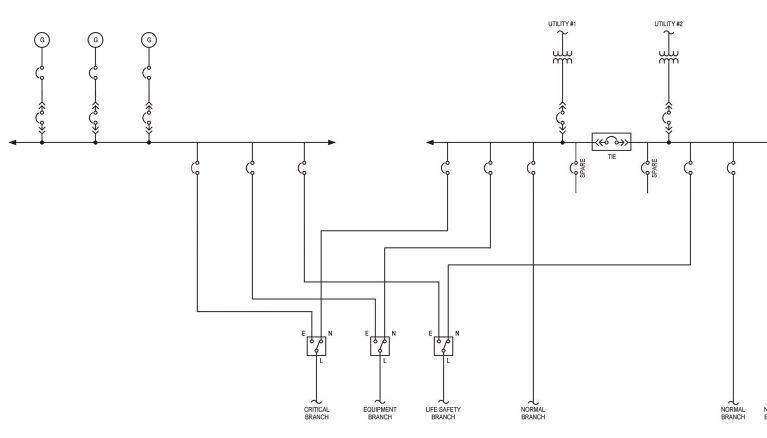
lenges and how the generator will be tested before operation.
NFPA 70: National Electrical Code (NEC) has several articles that apply to emergency power backup sources. It is important to review the code requirements when deciding on the classification of an alternate power source.
The most pertinent codes, standards and guidelines the design engineer must become familiar with are:
• NEC articles 517 health care, 700 emergency systems, 701 legally required standby systems, 702 optional standby systems and 708 critical operations power systems (COPS).
• NFPA 99: Health Care Facilities Code.
• NFPA 101: Life Safety Code.
• NFPA 110: Standard for Emergency and Standby Power Systems.
• ANSI/IEEE Standard 446: Recommended Practice for Emergency and Standby Power Systems for Industrial and Commercial Applications.
• UL 1008: Transfer Switch Equipment.
The NEC generally classifies three types of “generator backup” power systems:
‘ It is important to review the code requirements when deciding on the classification of an alternate power source. ’
• Emergency.
• Legally required standby.
• Optional standby.
Health care is the one major facility type that has completely different classifications, which we will review later in this article.
NEC Article 700 classifies emergency systems as “those systems legally required and classified as emergency by municipal, state, federal or other coded or by any governmental agency having jurisdiction.” The NEC further states that “these systems ... automatically supply illumination, power or both … essential for safety to human life.”
In practical terms this normally includes providing power to egress lighting, fire detection and protection, certain types of elevators, public safety communications or any system where loss of power would cause serious endangerment to life or health.
Further, section 700.12 states that “Current supply shall be such that, in the event of a failure of the normal power supply, emergency lighting, emergency power or both shall be available within the time required for the application, but not to exceed 10 seconds.” NFPA 110 contains additional requirements on classification of startup times.
The NEC also contains requirements for legally required standby systems in Article 701. Code-required standby systems may include communications, selected ventilation or smoke removal systems, lighting or certain types of industrial processes that may create hazards or hamper firefighting operations if power were not available. The code-required standby systems must be available within 60 seconds.
Another classification of loads is defined as optional standby systems and outlined in Article 702. Optional standby loads consist of electrical loads that do not affect life safety but would result in unacceptable financial or operational losses to a facility. Typical loads could include data processing, communication systems, refrigeration, selected
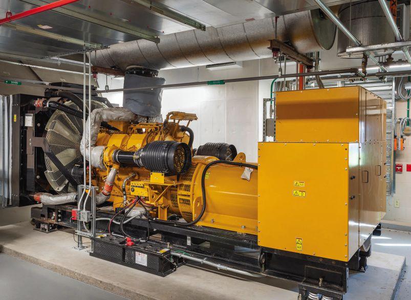
heating, ventilation and air conditioning (HVAC) loads and manufacturing or critical industrial processes. We will discuss a few of these common applications below.
NEC Article 708: Critical Operations Power Systems was first introduced in the 2008 version of the NEC. These are systems, operations or facilities designated by local, state or federal government as “mission critical.” Examples include police or fire stations or other facilities for reasons of public safety, national security or business continuity. Additionally, this section has some notable requirements for engineering practices like commissioning, which have long been practiced in data centers, health care and other previously unclassified “mission critical” facilities.
Article 517 covers the requirements for health care facilities. While the topic of health care generator systems requires an in-depth discussion, we will summarize the key differences.
Hospitals require generators but they don’t use the term “emergency” or “standby” as discussed in Article 700. The hospital generator electrical system is called the “essential electrical system.” The essential system has three branches: equipment, critical and life safety. A one-line power diagram of health care systems is shown in Figure 1.
The hospital equipment branch is primarily mechanical systems used to support patient areas; there is some latitude to include additional systems on this branch related to hospital operations beyond direct patient care areas.
• Learn about generator code classifications, looking closely at NFPA 70: National Electrical Code (NEC).
• Understand generator specification considerations for mission critical facilities, such as generator auxiliary systems.
• Consider the process of testing and commissioning as it relates to codes and standards.
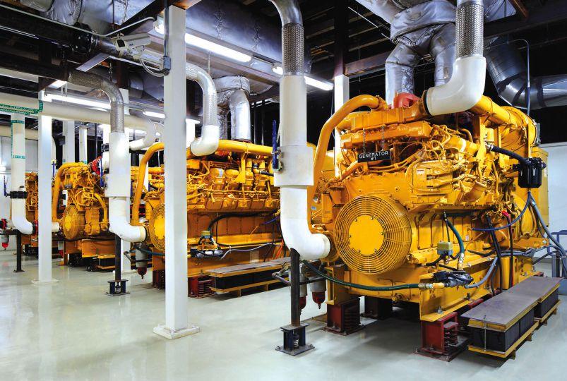
The critical branch generally services patient care areas, life support systems and other loads essential for patient care.
The life safety branch must meet the requirements of NEC 700, with a few specific exceptions as outlined in NEC 517.26. Typical loads include egress lighting, exit signs and fire alarm equipment.
Each hospital branch and system is required to be separated from other sources with a few exceptions and must be fed from a separate automatic transfer switch.
Regarding NEC Article 702 “optional standby systems” when would an engineer or client want a generator that was optional and not required by code?
Data centers are one example. They are the largest growing use for generators in the United States. The demand and shortages of generators are due, in part, to the significant purchase of generators for data centers. In every aspect of our lives from social media, to video streaming, big data and artificial intelligence, Americans rely on the continuous operation of data centers.
With data centers, nearly the entire facility is placed on a combination of standby generators and uninterruptible power supplies (UPS). In most data
center projects, all HVAC is on generator power and the data center equipment is also on a UPS fed by the generators.
The code complication for data centers is that they usually include some required Article 700 emergency loads such as egress lighting, fire detection and fire pumps. Rather than combining this emergency load with the optional generator load, it makes sense to provide smaller dedicated generators for core required emergency power and a separate larger generator for the optional backup loads in a data center.
Beyond data centers, certain types of science and technology buildings such as research and development, laboratories, semiconductor manufacturing, biopharmaceutical and chemical processing plants would also have a combination of both emergency and optional generator loads.
In these facilities, a careful review is needed to classify certain systems as either emergency, legally required standby or optional standby. A unique component of some labs and processing facilities is the use of hazardous or toxic chemicals and gases, which would require generator backup to prevent life safety concerns for control, treatment and ventilation.
There are a few common items for the engineer to consider further when selecting or applying generators in facilities.
Loading and sizing: It is highly recommended that a generator sizing program be used when calculating loads. Inductive loads, such as motors and transformers, present special concerns with inrush, which can result in voltage drops and generator stability. Transformers are commonly overlooked in this regard when being energized by a generator.
Electronic or nonlinear loads (computing, lighting, variable speed drives, manufacturing automation, lab equipment, etc.) may present issues with harmonics and voltage regulation. It is not uncommon for data centers to present leading power factor, which presents problems with voltage regulation.
One item that is can be confusing to engineers who are new to generators it the power factor rating of generators. Engine generators are “kilowatt (kW) limited,” that is, they are rated using a 0.8
lagging power factor. Therefore, engineers need to focus on using the kilowatt rating as well as the kilowatt volt-amp rating of a generator.
An additional consideration for sizing is that most engine-driven generator sets are rated for 77°F. You must derate 0.4% for every 10°F above 77°F. Most generator sets are rated for 3,300 feet above sea level. You must derate the unit by 1.5% for every 1,000 feet above that altitude.
Combining code required emergency loads with optional standby loads: When a single alternate power source, such as a generator, is used to supply both emergency and nonemergency loads, the system must be carefully reviewed. Emergency and nonemergency loads are allowed to be placed on a single generator under certain conditions. Unless the generator has the capacity to handle the full load (including starting currents), load shedding or sequencing must be implemented on the nonessential loads.
Generator power distribution: Per NEC 700.10, emergency circuit wiring must be routed separately from legally required or optional standby circuits. However, legally required standby circuiting may be combined with optional and other loads.
Emergency generator power distribution systems must also have fire protection when installed in buildings with occupancies of 1,000 people or greater or in certain types of buildings that are taller than 75 feet. This fire protection shall be accomplished by one of two methods:
• Installing the distribution in spaces protected by sprinklers.
• Providing a 2-hour-rated enclosure for the circuit wiring.
The fire protection requirements also apply to the physical feeder circuit equipment itself (panels, transfer switches, etc.), which must be in 2-hour-rated rooms or rooms with fire protection (see Figure 2).
Per NEC 700.30, emergency generator power distribution systems also are required under the NEC to be selectively coordinated. This will require a protective device coordination study, looking at fault levels and overcurrent devices to ensure that faults are isolated by opening the protective
GENERATOR DOCKING STATIONS, essential for modern electrical systems, have gained popularity for their role in enhancing resilience and meeting NFPA 70 code requirements
Generator docking stations have rapidly become a common piece of equipment to accompany generator installations. The increased use of docking stations can be attributed to owners’ desire for increased resiliency and because of recent code requirements in NFPA 70: National Electrical Code (NEC).
NEC Article 700.3(F), titled “Temporary Source of Power for Maintenance or Repair of the Alternate Source of Power,” requires that emergency systems with a single generator “include permanent switching means to connect a portable or temporary alternate source of power, which shall be available for the duration of the maintenance or repair.”
A typical location to place a docking station in the electrical system is between the generator and the generator distribution panel (see Figure 6). This configuration is ideal for situations where the docking station can be physically placed near the permanent generator location. Particular attention should be paid to the quantity and location of circuit breakers, which are specified integral to the docking station.
It is recommended that the docking station be specified with a circuit breaker configuration that fully isolates the generator conductors from the temporary generator source. Specifiers should also consider whether a load bank connection could also be beneficial to the installation, as it is relatively simple to upgrade a generator-only docking station to a dual-purpose (generator/load bank) docking station.
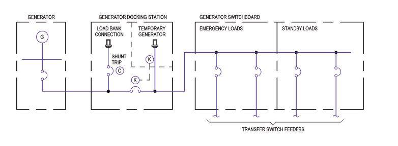
device nearest the fault, allowing the rest of the system to function. Optional standby systems are not required to be selectively coordinated.
Typically, generators have been selected at 208/120 or 480/277 volts (V). However, with increasing backup generation needs for criti-
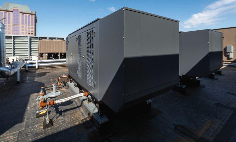
cal facilities or campus settings, there has been an increasing use of medium-voltage generators, particularly in the 15 kV medium-voltage class. The benefits of medium-voltage generators are to allow larger power ratings, often 2.5 megawatt and above, while being able to use smaller power cables and benefit from longer distribution runs without significant concerns over voltage drop. While there is a modest cost increase to select medium-voltage generators, this needs to be considered with savings in cable sizes as well as other cost changes in the medium-voltage power distribution system.
Medium-voltage generators require additional considerations by the engineer and include evaluation of increased code clearances, requirements for resistance grounding and a discussion with the owner on availability of qualified maintenance staff who are experience in working with medium-voltage systems. Using medium-voltage generators can require additional transformation back down to 480 V, impacting the cost and space requirements of additional transformers.
When power demands are significant or where redundancy (N+1) is needed for backup generation, paralleling is an option for evaluation by the consulting engineer. Historically paralleling was a complex process, but advanced digital controls have improved the design and specification process. One of the more common concerns was the start up time to bring multiple generators online and synchronized. Currently most major manufactur-
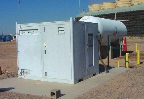
ers offer onboard paralleling controls on their generators, which has drastically reduced the startup times (see Figure 3).
In 2017, NEC Article 700.3 introduced a requirement for single use, emergency generators to use a docking station. This was common good practice for critical facilities needing back up power, but is now required for emergency generators.
There are two common fuel choices when considering generators: diesel and natural gas. Natural gas generators can be used in optional standby systems and with generators less than 500 kW (see Figure 4).
When considering generators for emergency systems, the possible interruption of a natural gas utility source and the 10-second startup time normally leads engineers to specify diesel. The amount of onsite fuel should be sufficient to provide a minimum of 2 hours of run time per NEC Article 700.12.D.2. Additional time requirements for on-site fuel can be found in NFPA 110.
In many cases where generators are used, the desired run times are much longer. It is not unusual to see 8, 24 or even 72 hours of fuel needed for some mission critical facilities. In these cases, the engineer will need to carefully examine where to store the fuel. “Belly tanks” under the generator are common, as are separate fuel tanks. The size of these storage tanks can be very significant and the use of belly tanks may notably elevate the generator and require catwalks for access. NFPA 110 Article 7.9.5 specifies a maximum of 660-gallon diesel
storage inside or on the roof of a structure. This requirement is in part based on concerns over fire and explosion hazards within a building.
Decarbonization goals and desire for renewable energy have led to the development of generators using hydrogen or hydrotreated vegetable oils (HVO).
There has been increased interest in hydrogen as a fuel source. Limitations currently exist in both the size of fuel cells and microturbines using hydrogen. Typically, these range in size from 100 to 200 kW. Conventional natural gas generator manufacturers have begun producing engines that can run on a blend of natural gas and hydrogen.
There remain challenges in the production, delivery and storage of hydrogen on sites. The Department of Energy has been addressing this by building regional hydrogen hubs and various manufacturers have begun to produce hydrogen via onsite generation units (see Figure 5).
A significant opportunity to move toward decarbonization with standby diesel generators is with HVO, a next-generation fossil-free fuel. This versatile fuel requires no changes to engines, doesn’t degrade over time and can blend with regular fuel. HVO should not be confused with previous generation biodiesel fuels. HVO is produced from organic agricultural waste products, but it uses hydrogen to drastically reduce the carbon content.
Using HVO in existing generators, in place of fossil diesel fuel, can reduce carbon emissions by up to 90%. HVO can be kept for up to 10 years without notable degradation and it is not susceptible to oxidation, water absorption or bacterial growth. As a newer fuel source, production and distribution is quickly ramping up across the country but limited in some locations. HVO carries about a 10% cost premium over standard diesel depending on location.
Along with paralleling switchgear, transfer switches and many other associated electrical equipment, generators are experiencing significant shortages and delivery delays. Generators may require 18 to 24 months to arrive on a project after approval for purchase.
Engineers are strongly encouraged to review all electrical equipment needs with the owner and construction manager to determine if early “long lead” packages need to be released before the completion of construction documents. This will require careful analysis and understanding of risks with the client in releasing these systems for early procurement.
‘ The amount of on-site fuel should be sufficient to
For both emergency and legally required standby generators, testing is required. There are two types of tests to be performed: The first is an acceptance test done upon installation but before becoming operational. A good source for acceptance testing is in various codes, such as ANSI/NETA ATS-2021 and NFPA 110 Chapter 8.
The second test is operational testing to be performed periodically, subject to the local authority having jurisdiction, during the life of the system. NPFA 110-2010, for example, has requirements for testing and maintenance procedures. Written records are to be maintained for either type of system. Of note, emergency systems are required to be tested “under maximum anticipated load” whereas legally required systems are required to be tested “under load.”
As mentioned earlier, generators are also used in COPS defined under NEC Article 708. This section goes beyond the testing required for emergencies and legally required standby systems to require commissioning.
Commissioning is a common practice in all mission critical facilities and includes component, system, baseline and functional performance tests.
There are notable differences between emergency and standby generators within NEC. The engineer should be careful in using the terms and understand the requirements, considerations and specifications when designing generator power. cse
Brian Rener, PE, LEED AP, is Director of Mission Critical Facilities at SmithGroup. He is a member of the Consulting-Specifying Engineer editorial advisory board and has been writing for the brand for more than 30 years.
Generator insights
u Topics include code requirements for the load type to be powered, backup, standby and emergency generators.
u Special facilities such as data centers, hospitals or campuses may lead to considerations for mediumvoltage or paralleling systems.
u Additional systems considerations include a growing desire for sustainable and renewable alternatives to traditional diesel and natural gas fuels.
u This article assumes that the engineer is familiar with engine generator basics and therefore focuses on some specific or unique considerations for using a generator and their applications.
Lilly Vang, PE and Joshua Hunter, PE, CDM Smith, Maitland, Florida
When selecting a generator, one of the first and most important decisions is which fuel type to choose
When a generator is required, whether for emergency or nonemergency situations, it is important to choose the optimal fuel type based on the capacity and application. Each fuel type offers its own advantages and disadvantages. These can include fuel costs, fuel availability, reliability, environmental impact, generator performance, initial generator cost, generator size, generator availability, fuel storage and delivery methods and code/ standard requirements.
Standards, industry guides and codes relating to generator and generator fuel include, but are not limited to the following:
• NFPA 30: Flammable and Combustible Liquids Code: guidelines for flammable and combustible liquids.
• NFPA 54: National Fuel Gas Code: guidelines for fuel gas piping systems, equipment and related accessories.
• NFPA 70: National Electric Code (NEC): Articles 700, 701, 702 and 708 provide guidelines for the installation of emergency and nonemergency systems.
• Learn about several generator fuel types.
• Understand the advantages and disadvantages of different fuel types for different applications.
• Know what to consider when choosing a generator fuel type.
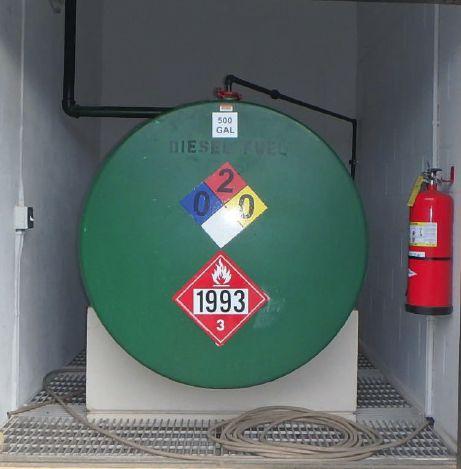
• NFPA 110: Standard for Emergency and Standby Power Systems: guidelines for emergency and standby generators.
Some common generator fuel types include diesel, natural gas, propane and gasoline. Each of these fuel types can be the best fuel type for any given project application. To choose the best generator for any project application, it is important to first understand a little about each fuel type, the disadvantages, the advantages and generator availability.
Diesel fuel is a distillate fuel oil refined from crude oil and biomass materials. It is a commonly used fuel for many vehicles, including buses, trains, military vehicles and freight and delivery trucks. It is also a common fuel for generating electricity using diesel-engine generators. There are many types of diesel fuel, such as diesel #1, diesel #2 and biodiesel. The most widely preferred is diesel #2. It is the preferred option because of the presence of paraffin wax, which
has a lubricating effect, lowering the volatility and increasing the viscosity of the fuel. This effect protects the design engine and other components from extended wear, tear and abuse. Diesel #2 is also a readily available and cheaper fuel option with higher energy content than diesel #1.
The one downside to diesel #2 is that the wax will cause a gelling effect during cold winters, which could cause the generator to start poorly — or not at all. During these times, it may be better to use diesel #1.
On the other hand, biodiesel, while perfectly capable of running a diesel generator, is more sensitive to both cold and hot temperatures, has a shorter shelf life and is generally less readily available. Hot weather can cause biodiesel fuel to mold, while cold weather can harden the fuel, making it difficult to dispense.
Installing diesel generators offers an efficient and reliable backup power system for the following reasons:
• Diesel fuel is less flammable than other fuel types.
• Fuel tanks can be easily located and stored onsite, ensuring external disasters or sabotage will not affect a facility.
• Diesel generators have the best transient response time compared to other generator fuel types.
The downsides of diesel generators include high emissions, high fuel costs and high noise levels during operation. For emergency generators, the emissions may be less of a concern, but nonemergency operation of larger generators require a Tier 4 unit (or greater in some locations) to meet U.S. Environmental Protection Agency (EPA) regulations. These units are more expensive and complex due to emission treating accessories, creating a higher chance for equipment malfunctions and maintenance. For noise levels, there are mufflers that can help reduce noise and the generators can be placed in a sound-attenuated walk-in enclosure or building. Figure 1 shows a 500-gallon diesel fuel tank located in a building at a wastewater lift station. However, not much can be done about the high fuel cost of diesel besides using the generators as infrequently
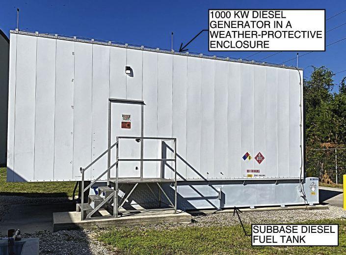
as possible, only for maintenance, testing and emergency situations.
Diesel generators are available in nearly any size needed and are the typical choice for industrial applications that require a reliable emergency backup power system and on-site fuel. Figure 2 shows a 1,000-kilowatt (kW) diesel generator with a subbase fuel tank sized big enough to provide power to a water treatment facility for 72 hours. Diesel fuel tanks can be provided in a variety of sizes, providing power for five, seven or even 20 days and can be mounted external to the generator unit.
However, diesel fuel will eventually degrade, which will start to happen in as little as 28 days and result in the fuel being unusable in 6 to 18 months. Therefore, the larger the fuel tank, the more the generator will need to be run for testing. Another option to mitigate degradation of diesel fuel is to include fuel polishing as a regular maintenance procedure. While fuel polishing adds an additional cost, it is far cheaper than continually replacing the diesel fuel, which typically has a high dollar to gallon cost.
These units are best when installed permanently on-site or mounted on a portable trailer. Diesel fuel type generators are typically not as good of a choice for smaller scale portable applications, such as households and camp sites because of the generator weight and initial cost.
‘ Although natural gas is cleaner, many jurisdictions have been extending decarbonization efforts to natural gas burning equipment. ’
Applications requiring nonemergency use and facilities that are concerned about high emissions will likely not want this fuel type due to the high fuel costs and high emissions produced.
Natural gas is an odorless, gaseous mixture, predominantly made up of methane. Natural gas is commonly used for heating, cooking, power generation and other industrial uses. This fuel type is so prevalent that it accounts for about 30% of the energy used in the United States, about 40% of which is used for electric power production.
Natural gas generators provide a more environmentally friendly and operationally cost-effective alternative to diesel generators because:
• Natural gas is typically a cheaper fuel source than diesel.
• Emissions from a natural gas generator are less than those from a diesel generator.
The advantages of natural gas fuel being cheaper and producing fewer emissions will have a smaller benefit if the generators are operated only during emergency situations. If the generator is used continuously or more often for nonemergency applications, such as demand response, the cheaper fuel source and reduced emissions would provide more benefits. This will depend on regional pricing; however, most areas in the United States have a source of cheaper natural gas supply compared to diesel fuel costs.
Although natural gas is cleaner, many jurisdictions have been extending decarbonization efforts to natural gas burning equipment. For now, emergency power generation has been exempted from many of these restrictions; however, there is concern in the industry that natural gas generators will eventually not be exempt from these decarbonization efforts.
The downsides of natural gas generators include higher initial costs for the generator, slower transient response time compared to diesel, an increased engine footprint and reliance on continued service from a local natural gas utility, which may have inadequate service capabilities and susceptibility to external disasters or sabotage affecting the natural gas pipeline.
The generator's higher initial cost becomes prevalent when the unit is larger than about 150 kW. This is when the diesel driven engines become more cost effective to produce than natural gas generators. For example, a vendor quote for a 2,500 kW natural gas generator came out to be roughly 45% more expensive than a 2,500 kW Tier 2 diesel generator.
The slower response time also only becomes an issue for larger generator units, as a 2,500-kW natural gas generator with a 10-second startup time can be procured from a major manufacturer. Generator units larger than 2,500 kW will typically have startup times of 60 seconds or longer. This can be a disadvantage for high priority loads or varying loads as the generator cannot begin to power the facility until it has finished achieving ready to load status, whether it happens within 10 seconds or 60 seconds. The generator set will also take longer to change speed to account for changes in load. This disadvantage will be less problematic for supplying continuous loads, which do not vary frequently.
The biggest reliability concern with using natural gas is the reliance on the natural gas utility, essentially not mitigating the same risks associated with reliance on the electrical utility supply. A standby system reliant on off-site infrastructure is less attractive for a facility that needs a reliable and resilient backup power system.
Moreover, obtaining permission from the relevant authority may be required to use the natural gas pipeline for backup power generators. The natural gas utility may not even have the capability of supplying natural gas at a high enough pressure to operate a larger generator. This can require gas booster pumps, which would need its own backup power generator during utility outage events. These limitations can make this fuel source not practical for certain facilities.
As for available sizes, natural gas generators are manufactured in nearly every size needed. The units are not quite as reliable as diesel, but close and they will need a natural gas source, which will need to be piped in by a utility. This all but eliminates the ability to have a portable natural gas generator unit.
Where natural gas generators truly shine is nonemergency, continuous-use industrial applications. This takes advantage of the much cheaper and cleaner fuel source. Several natural gas models will even be designed specifically for this type
of operation. Natural gas units are an ideal choice for combined heat and power (CHP) systems and many power plants use large scale natural gas generators. Even for emergency situations, natural gas generators can provide good utility redundancy if power from an electrical utility is lost.
As discussed previously, generators can be used as an emergency backup power source, as a primary power source or for nonemergency applications. Choosing the right fuel type depends mainly on the needs of the facility, physical and design limitations of the area and the life cycle cost of the generator and its fuel type. The following sections detail four generalized considerations to determine the fuel type that best matches the end user’s needs.
The first step is to understand the load profile of the electrical demand and determine the capacity of the generator needed for the facility. The term “facility” is used loosely throughout this article to represent the end user and can be a business, industrial sites, etc. Power usage for a facility typically follows three main types of profiles: residential, commercial and industrial.
Residential facilities typically have the lowest demand, then commercial and finally, industrial. The total amount of power usage is also reflected in the size of the facility. A commercial facility is often much bigger than a residential facility and typically has more loads. An industrial facility may at times be smaller in footprint than a commercial facility, but may have larger motor loads, which have higher demands than the lights and receptacles commonly seen in a commercial facility. Harmonics and inrush caused by motor loads can and will increase the size of the generator required for the facility even though the average demand does not appear as high.
A common misconception is the loading of the generator. Not all generators are recommended to be 100% loaded. Emergency standby rated generators, depending on the generator manufacturer’s recommendation, work best around 70% loaded. For example, a 100 kW generator is ideal for a facility that has an average 70 kW demand with peak demand of around 75 to 80 kW. Other generators,
such as prime rated and continuous generators may perform best when loaded up to 100%. Knowing the optimal loading characteristics will ensure the generator unit lasts as long as possible and has the greatest fuel efficiency.
The capacity of the generator, whether that is 100 or 1,000 kW, greatly affects the selection of fuel types available. For example, if the capacity is high, fuel types such as propane and gasoline are typically not efficient or practical.
After understanding the type of demand, the operation of the generator needs to be determined. Generators can be operated when needed due to potential hazards for critical life safety and/or critical operation resiliency, during peak electrical utility rate times or continuously for power generation, such as a microgrid, CHP system or power plant.
Determination of the generator operation should consider the needs and operation of the facility. If the facility is legally required and classed as emergency or critical life safety by municipal, state, federal or by any governmental authority having jurisdiction, the facility will need a generator that can start within 10 seconds. The emergency system is intended to supply light and power to designated areas in the event of normal power failure to support safety to human life. Out of the fuel types discussed, only diesel and some natural gas generators can start within 10 seconds of power outages.
Most facilities are not required to have emergency backup systems but can be legally required to have standby systems. They are intended to supply power to selected loads that could create hazards or hamper rescue or fire-fighting operations in the event of normal power failure.
Generators can also be operated as the primary power source or operated during peak electrical utility rate times for peak shaving or demand response. Generators must meet EPA emission regulations and/or federal, state and local regulations for these nonemergency types of operations.
Any critical facility can participate in demand response if the EPA emission regulations and code requirements for emergency systems are met. In other words, diesel generators need to be Tier 4 generators to meet EPA emission regulations for
csemag.com
u When considering backup, standby or emergency power for a building, generators are typically specified.
u The type of fuel to power a generator is often determined by codes and standards, storage and delivery and application, among other things.
u This article presents the advantages and disadvantages of several common generator fuel types for different applications and sizes and provides a list of three considerations to help with the decision.

nonemergency operations. The other fuel types, depending on the size, have emissions that meet EPA emission regulations.
STEP 3: Review additional limitations in the area
Step 3 considers the limitations caused by the facility location. The next few portions cover a few but not all the critical topics of consideration for selecting the type of fuel source.
Federal, state and local codes and ordinances: Federal, state and local codes and ordinances
Check Valve for VFD Drives
Introducing the VFD Check Valve, the first Center Guided Silent Check Valve developed for VFDs.
Metraflex re-engineered a classic hydronic component to improve e ciency and cut costs
The VFD Check Valve
• Hydrodynamic disc design increases flow.
• Provides superior functionality in low-flow conditions, common with VFD drives.
• Same face-to-face dimension as common globe-style center-guided check valves.
© 2024 The Metraflex Company
vary based on the location of the facility. Some locations are more stringent than others. Per NEC Articles 700-702 and 708, emergency, standby or prime mover generators, in general, cannot be solely dependent on a public utility gas system for their fuel supply. They are required to either have another dual fuel supply or a supply that can be stored on-site.
NFPA 110, Annex A also provides additional requirements and considerations for the fuel type depending on whether the generator is a prime mover, standby or emergency type. For example, Annex A, Chapter 5.1.1(1) of NFPA 110 details that diesel fuel used for prime movers should not contain biodiesel if the fuel is stored longer than six months.
Certain state and local codes and ordinances also limit the noise created by the generator, particularly for residential areas. Therefore, soundproofing may need to be considered. Diesel generators tend to be the loudest and require more sound proofing to meet codes and ordinances.
Fuel availability: Depending on the location of the facility, the availability of the fuel also affects
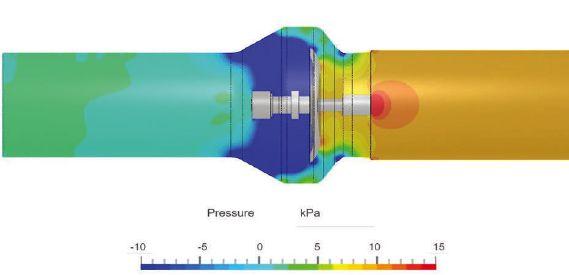
Pressure Drop Across the 6-inch VFD Check Valve
www.Metraflex.com/VFD sales@metraflex.com
the selection of the generator type. For example, obtaining natural gas fuel in a very rural area may be next to impossible or not very cost effective because a new gas pipeline would need to be installed.
Physical limitations: The available real estate for the generator and its associated equipment (fuel tanks, emission correcting accessories, etc.) also plays a key role in the selection of the fuel type. Gasoline, propane and smaller natural gas generators tend to be smaller and lighter for residential, casual applications such as camping or small-scale backup power on a construction site. On the other hand, gasoline, propane and diesel generators require additional space for fuel storage.
Manufacturer availability: Manufacturer availability also plays a key role in the selection of generator fuel type. Having a local manufacturer’s factory nearby or even a local generator representative to contact for maintenance or operation concerns can help ensure the generator has an optimal life cycle.
STEP 4: Perform a life cycle cost analysis
The last step is to consider the life cycle cost of the fuel types that are feasible for the facility. This step allows the end user to accurately select or justify the usage of the selected fuel type. A life cycle cost analysis is typically reviewed over a period, which may be for as long as the manufacturer’s recommended generator life expectancy/maximum operation hours.
The total life cycle cost can be broken down into three major types: initial expenses, future expenses and residual value.
The life cycle cost for each feasible fuel types can then be compared to determine which fuel type is most cost-effective solution over the generator’s lifetime. cse
Lilly Vang, PE, is an electrical engineer at CDM Smith, focusing on the design of electrical power systems. She is a 2024 40 Under 40 award winner.
Joshua Hunter, PE, is an electrical engineer at CDM Smith, experienced in the design and analysis of electrical power systems.
• Gasoline generators.
• Propane generators.
• Tier 4 requirements.


Miura’s modular installation automatically adjusts (load-following technology) to match your steam demand. When you only require 25% or 50% output (as illustrated), the system only brings on the units needed to carry that load. That’s a tremendous cost and resource-saving advantage in the long run. Better yet, when your facility does not require steam, the boilers automatically go into standby mode reducing runtime and conserving resources and emissions output.


Matt Koukl, DCEP-G, Affiliated Engineers, Inc.
Increased focus on unique cooling solutions for data centers address limitations of traditional systems.
Every day, zettabytes of data navigate a global infrastructure of thin glass strands. From medical imaging to streaming movies, data transmission starts by processing data through informational technology (IT) equipment connected to various data center facilities. IT hardware generates heat as it works to process, store and transmit data. For every watt of power distributed to a server, the same amount of heat is generated and needs to be removed. Most electronic devices can operate within an allowable temperature range, but exceeding these limits can lead to reduced efficiency and, in extreme cases,
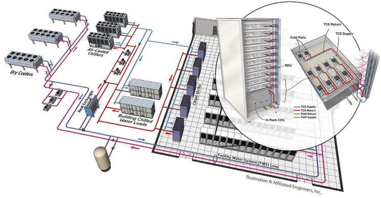
hardware failure. For systems to remain operational, data centers need to implement sophisticated and redundant cooling systems to maintain optimal operating temperatures.
Traditional air conditioning systems have been used for decades to maintain suitable temperatures and prevent equipment from overheating. However, these traditional systems become limited as data centers began to house densely packed powerful servers and their associated processors.
Traditional air-cooling systems feature a raised access floor system with cold air generated by a computer room air handler (CRAH) or a computer room air conditioner (CRAC) unit. CRAC and CRAH units contribute to precision cooling, humidity control and overall efficiency of data centers by ensuring IT equipment operates within specified environmental parameters. CRAC units employ a refrigeration cycle to cool the air, while CRAH units use chilled water hydronic systems. Both units distribute cooled air through raised floors or overhead ducts, contributing to even airflow and temperature distribution.
CRAC and CRAH units remain popular solutions due to cost, ease of installation, flexibility to scale quantity of units and simplicity of control. While they are effective for many data center applications, there has recently been an increase in alternative cooling methods and derivatives to the CRAC and CRAH units for better efficiency and sustainability. These derivatives have advanced in capability from the need to handle increasing IT equipment heat loads and the substantial scale increases of today’s computing facilities.
In-row cooling units are cooling systems explicitly designed for data centers to manage and control the temperature within server rows or small spaces. Unlike traditional perimeter-based cooling sys-
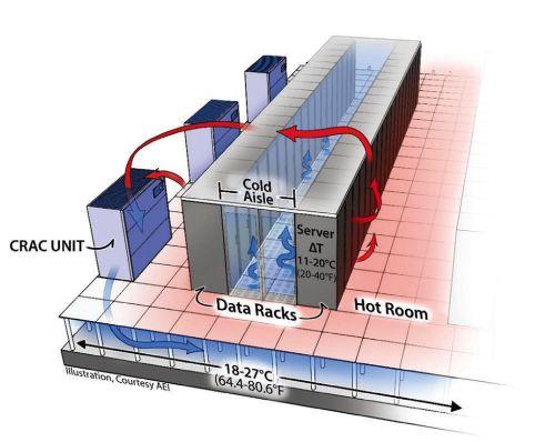
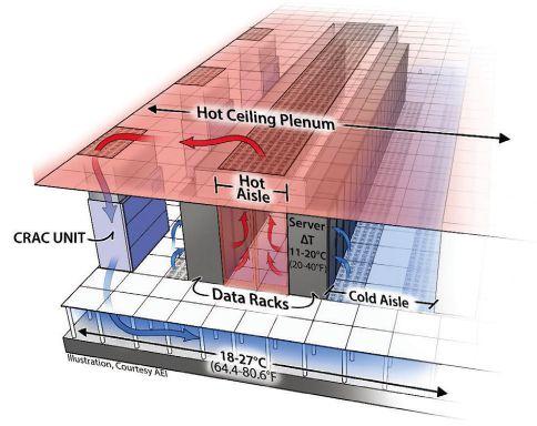
‘ Cloud computing significantly impacts the
data center facility scale, and the supporting power and cooling systems.
’

tems, in-row cooling units are strategically placed between server racks, bringing the cooling source closer to heat-producing IT equipment. This proximity enhances the cooling efficiency and allows for more precise temperature control. When coupled with hot or cold aisle containment, these units enable higher cabinet power densities and efficiency. Through empirical data and modeling, separating hot and cold air with air containment allows higher IT equipment power densities without the fear of increased IT equipment temperatures from hot air re-entrainment.
Air containment and the separation of hot and cold air comes in many forms. The most common is hot and cold aisle containment, which forms a barrier over the aisle with two rows of IT equipment cabinets and doors at the end of each aisle. This alignment prevents hot and cold air from mixing and optimizes overall cooling system efficiency.
Passive chimneys, also known as passive cooling chimneys, are another option to optimize heat dissipation and airflow management while reducing the energy use of mechanical cooling systems. Employing a chimney requires the IT equipment cabinets to have solid rear doors and to be fully sealed.
Rack-based or chimney containment enables the containment of single cabinets without needing the two rows of cabinets to form an aisle. The containment method is typical in enterprise data centers or colocation facilities where a few cabinets might be in a cage. This method can be implemented in new and existing facilities, offering a scalable solution that accommodates changes in cabinet power density or data center layout.
One of the most impactful computing changes to data center cooling design was the implementation of cloud computing. Cloud computing significantly impacts the data center facility scale, and the supporting power and cooling systems. Cloud data centers are generally five to 10 times larger than traditional enterprise data centers, with a magnitude of around 20 to 80MW of IT load per facility. This “hyper-scaling” of the data centers changed the way data centers were built and cooled. A standard design methodology to scale equipment and systems for these substantial hyperscale facilities uses air-cooled chillers and fan walls for air distribution.
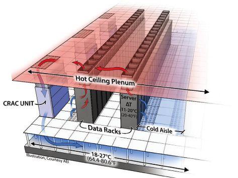
As demand for data and data processing increases, data center facilities continue to expand, amplifying the need for cooling systems to adapt to the scale of these extensive facilities. To increase cooling on a larger scale, expansive facilities require large fan wall systems. These sizable air handlers, containing 12 to 16 fans arranged in a grid, are designed to supply large volumes of air above 80,000 cubic feet per minute (CFM). These units can have limited fan redundancy built into the design to support a fan failure. Depending on facility operation and maintenance procedures, the failed fan could be replaced with a critical spare that limits downtime. Typically situated around the perimeter of the data center’s technical space, these units circulate cooled air throughout the data hall with-
A ment, also known as a
like this one is in data centers. Affiliated Inc.
FIGURE 4: A cabinet/ rack ducted containment, also known as a chimney containment, like this one is typical in enterprise data centers. Courtesy: Affiliated Engineers, Inc.
u
• Understand different approaches to data center cooling.
• Identify necessary considerations for liquid cooling deployments.
• Learn how to implement heat reuse in data centers.
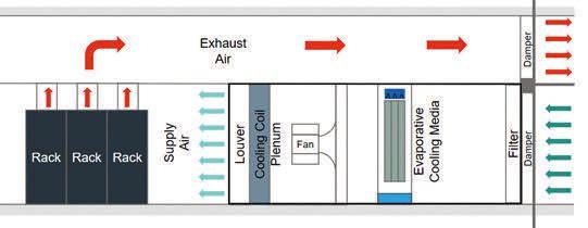
out needing a raised access floor. This method, known as flooding, necessitates air containment to segregate hot and cold air streams. Without such containment, restrictions on IT equipment cabinet densities would arise, requiring a lower supply of air temperature and significantly increased air volume to manage the mixed air conditions within the space.
In low humidity climates, large data centers also commonly employ either direct or indirect evaporative cooling to enhance energy efficiency without relying on compressors. The indirect and direct evaporative cooling processes operate similarly to a cooling tower, except they cool air rather than water. Direct evaporative cooling uses outside air or the hot, dry return air from the data center to flow across wetted media in an air handler before being circulated back into the data hall. Since the outside air typically has a low wet bulb temperature, it cools the air in a natural cooling process by evaporating the water. However, the downside of this process is that it directly introduces outside air into a data hall, potentially affecting servers and other devices susceptible to corrosive environments.
The alternative to direct evaporative cooling is indirect evaporative cooling. Indirect evaporative cooling recirculates and returns air across a medium with liquid flowing outside the airstream in the data hall. Manufacturer’s use different heat exchanger materials; some use aluminum plates, while others use a polymer tubes. In both cases, the air does not directly touch the water. While generally less efficient than direct evaporative cooling, the indirect method eliminates the challenges of introducing outside air into the data center and the associated control complexities.
In direct and indirect evaporative cooling processes, it is crucial to maintain water chemistry through chemical treatment systems. Similar to the systems employed for cooling towers, chemical treatment systems must regulate the PH level to minimize calcium buildup on the different media types. Moreover, maintaining proper water chemistry and filtration for reusing discharged water is
critical to increase the cycles of concentration and reduce the need for makeup water in the system, especially in geographic locations with concerns about water availability.
For large facilities, bringing outside air directly into the technical space for cooling IT equipment depends on various factors like location, climate and adherence to temperature limits outlined in the most current version of ASHRAE Technical Committee 9.9 Thermal Guidelines. This approach poses many benefits, including simplified system design, reduced components and costs, and lower maintenance and operating expenses. However, there are significant design considerations related to control, geographic location, filtration and the potential risks of air pollution or corrosion to the IT equipment.
Over the last decade, several significant factors have contributed to the increase in data center power density, including the following:
• Applications like artificial intelligence (AI) and machine learning (ML) with parallel processing utilize high-powered graphics processing units (GPUs).
• Densifying software applications through virtualization and increasing server power utilization to support running multiple applications on a single server.
• Increases in computing software utilization.
• Decreasing processor case temperatures reducing hours of economizing availability.
• General growth in demand for data and the processing of the data.
As a result of advancements in chip technologies, which allowed multiple virtual servers to operate within a single physical server, power demands continue to rise. Consequently, data centers gradually became more densely packed with IT equipment. Average densities, which hovered around 2.2kW/ rack in the mid to late 2000s, have almost quadrupled to approximately 8.5kW/rack, with peak den-
sities reaching about 20kW/rack. This increased density posed challenges for air cooling systems to dissipate the generated heat effectively and efficiently.
New products, like rear door heat exchangers, were introduced to the market to address higher density loads at these cabinet power densities. There are two types of rear door heat exchangers: passive and active. Passive rear doors resemble a cooling coil integrated into the rear door of the IT equipment cabinet. They rely on IT equipment fans to circulate air across the coil. A drawback to this method is that it requires the IT equipment fans to overcome the resistance of the coil. In general, IT equipment manufacturers do not typically design their hardware or associated fans to handle additional resistance beyond the server's internal components.
Alternatively, active rear door heat exchangers employ fans that draw air from the IT equipment exhaust through the coil, reducing the workload on the server fans. These active systems can measure pressure in the rear of the IT equipment cabinet to alleviate the pressure (resistance) imposed on the server fans.
Within the last decade, the rapid expansion of virtualization of applications has led to most applications being virtualized to their fullest extent and hosted in a cloud environment. This has notably decreased the number of servers required and the footprint needed for computing systems. However, despite these advancements, the growth and demand for computing has outpaced the progress of server virtualization due to the belief that software development has caught up with hardware capabilities.
To meet the increasing demand for computing, cloud applications and storage, data centers must expand in size and number. Today, data center campuses are approaching and exceeding a gigawatt capacity to accommodate a dozen or more buildings, and each building is expected to handle tens to hundreds of megawatts.
In the last three years, significant growth in applications to support ML, AI and large language models has occurred. These applications require a substantial increase in computing power to perform operations and produce results within a reasonable timeframe. To achieve these results, a combination of high-powered general-purpose graphics processing units and other high-powered central processing
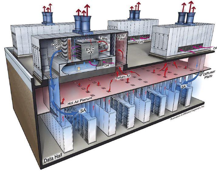
units (CPUs) are necessary to generate the results within a reasonable timeframe. Commonly, multiple GPUs are positioned in a server or server blade to support the computing. The blades and server chassis are arranged in large clusters to perform these calculations, resembling the traditional high-performance computing (HPC) clusters typical implemented for research computing (supercomputing). Today's cabinet power densities are growing and ranging from 50-500kW per computing cabinet.
The processors have increased in core count and onboard memory to achieve the desired outcomes. These advancements have substantially boosted the processor power, and chips with a thermal design power (TDP) range from 300 W to 1,000 W are becoming commonplace. It’s anticipated that processor power will continue to rise, and the thought of a 2,000 W processor in the coming years is an expected possibility. A critical factor concerning these dense, power-hungry silicon devices is the need for lower case temperatures to achieve computing performance.
The processor's integrated heat spreader (case) is the thermal interface point between a heat sink and the processor. As the processor’s TDP increases, many processors are experiencing a need to reduce the case temperature to mitigate against leakage current, causing the processor to consume more power.
The focus has shifted from air to liquid cooling, a concept familiar with cooling high-density comput-

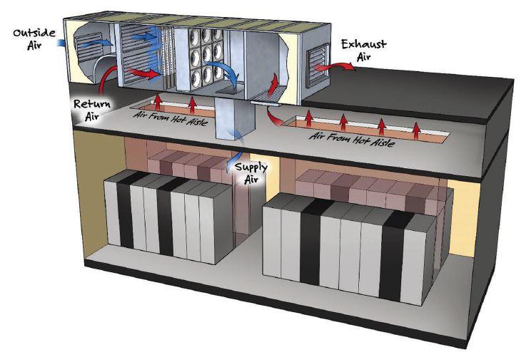

ing electronics to accommodate the cooling demands of these high-power processes. In 1975, Seymour Cray introduced the Cray-1, one of the first liquid-cooled supercomputers. Although the cooling technology employed in the Cray-1 differs from today’s standard liquid cooling methods, it sets the stage for future adoption and implementation.
Liquid cooling is gaining significant momentum in the data center cooling market for a few reasons.
Many liquid cooling options are arriving in the data center cooling market for various applications. Some liquid cooling solutions are better utilized in certain conditions than other alternatives, especially when it comes to the following: scale of deployment, concerns around liquid in the data center, fluid types, power densities, redundancy, overall cooling approach, location and application.
The two main categories for liquid cooling are immersion cooling and direct-to-chip liquid cooling (DLC).
od offers enhanced cooling capabilities, especially in scenarios with high heat flux components. These fluids are non-mechanical refrigerants that don’t require vapor compression cycle. However, consideration needs to be given to the global warming potential of these fluids, as it is higher than the single-phase fluids, but still lower than current mechanical refrigeration refrigerants.
The standard approach to immersion cooling uses a large container, like a tank, to house the liquid and IT equipment. If the immersion system is procured as a package, it is expected to come with controls, pumps, valves, heat exchangers and other telemetry to control the cooling operation. Most tanks are fabricated from painted carbon steel or stainless steel. The tanks will also have mounting locations outside the fluid for the power strips to deliver power to the IT equipment and switches for communication between the IT equipment. It is important to note that not all IT hardware vendor's equipment will come ready to be placed in a tank of dielectric fluid for cooling. Further, considerations for implementing this type of system need to include:
• Facility water temperature delivered to the tank.
• Lifting apparatus to lift the servers out of the tank.
• Spill cleanup.
• Containment for possible leaks.
• Fluid storage and disposal.
• Ancillary cooling for the heat rejected from the tank.
• Fire suppression system.
csemag.com
Data center cooling
u The evolution of data center cooling from air systems to liquid solutions is because of the need to adapt to high-power processing demands.
u Immersion and directto-chip liquid cooling methods offer scalable and efficient alternatives to traditional cooling methods.
In its simplest form, immersion cooling involves submerging the server, and all its components, into a dielectric, thermally conductive fluid. These fluids usually consist of either a single-phase fluid or a two-phase fluid.
Single-phase fluids do no change state and are in direct contact with the heated components to remove the heat. In general, the fluid is expected to circulate in the tank and across the components to remove the heat.
Two-phase fluids utilize the phase change of a liquid, transitioning from liquid to vapor, to absorb and carry away heat from the elements. This meth-
DLC also comes in single-phase or two-phase options for cooling the equipment. DLC uses cold plates directly in contact with the processor's case. The cold plate contains the fluid passing through microchannels to reject the energy produced by the processor.
DLC is typically focused only on processors and other high-heat flux components. Unfortunately, this leaves the less energy-intensive heat-generating components to be cooled by air. The computer room cooling system will commonly cool these components, which in turn cools also cools other IT equipment within the space, such as switches and storage hardware.
There are two types of DLC systems:
• Single-phase DLC: Fluids (deionized water or water treated with bacterial growth inhibitors) remain consistent within the cold plate and fluid network. This fluid circulates through the microchannels within the cold plate and then moves to a heat exchanger to dissipate the heat.
• Two-phase DLC: There is phase change of a liquid within the cold plate. The fluid enters the cold plate and changes from liquid to vapor through an evaporative process. The vapor is then returned to a heat exchanger, condensing into a liquid.
DLC, in general, has an extensive adoption base and has been implemented in many large-scale data centers and HPC computing systems worldwide.
There are two distinct loops of cooling fluid for immersion and DLC: facility water systems (FWS) and technology cooling systems (TCS). Generally, the TCS loop cools the IT equipment, and the FWS loop takes the heat from the TCS loop through an intermediary device, called a coolant distribution unit, to reject the heat outside the building.
The design of liquid cooling systems introduces new challenges for engineers compared to traditional air-cooling methods described earlier. During the design process, certain considerations need to be made with a perspective adjusted to the characteristics and requirements of liquid cooling systems. Some important considerations include system redundancy, water temperature, choosing single-phase or two-phase working fluid, filtration, fluid chemistry and potential leak impacts.
Although designing heat rejection and FWS loops is typically straightforward, additional opportunities exist to leverage the heat generated from the liquid-cooled systems. While air-cooled systems face limitations due to lower heat density and temperatures, liquid-cooled systems offer potential in these areas. When operating, the ability to capture heat from the computing systems is substantial and can potentially offset the need for other hot water heating sources. While this seems promising, there are numerous considerations to evaluate when implementing this approach, including:
• Computing systems availability and operational timelines.
• Interactions with the overall building systems.
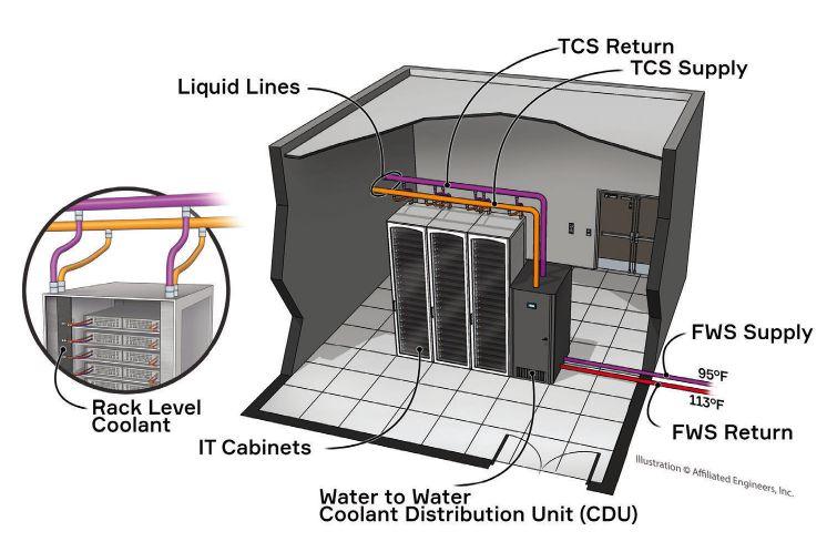
• Low temperature hot water system design.
• FWS and TCS water temperatures.
• Processor operation at elevated water temperatures.
• System components.
While heat reuse sounds intriguing, a waterside economizer might offer greater efficiency and lower capital and operational costs in certain climates and applications. If the objective is to diminish reliance on carbon sources for heating, reusing the energy captured in the water from computing systems could be a viable option. However, a thorough analysis is necessary to determine how it will be implemented and the overall impacts on the system.
The demand for efficient cooling solutions has shifted from traditional air systems to innovative methods in the dynamic landscape of data centers. The industry is evolving from in-row cooling units optimizing temperature control to immersion and DLC that address high-power processors. Integrating sophisticated cooling systems becomes paramount as data centers grapple with increasing power densities driven by technological advancements. The choice between immersion and DLC brings a nuanced approach to dissipating heat, offering scalability and efficiency. As the data center ecosystem navigates this transformative phase, the interplay between power-hungry technologies and cutting-edge cooling solutions defines the trajectory toward a resilient and sustainable future. cse
Matt Koukl, DCEP-G, Principal, Market Leader Mission Critical Madison, WI.
FIGURE 10: An example of liquid cooling equipment with facility water system and technology cooling system control loops.
Courtesy: Affiliated Engineers, Inc.
Eric Rushenberg, Sr. Lighting Designer, HDR, Omaha, NE
UL listing requirements when specifying emergency lighting controls.
Lighting controls have revolutionized energy efficiency, user experience and architectural expression. Occupancy sensing, daylight harvesting, dimming, color temperature tuning, individual luminaire addressing and third-party system integration are some of the countless advancements since the invention of the light switch by John Henry Holmes in 1884. While it can be easy to focus on these exciting advancements, occupant safety and code requirements cannot be overlooked.
The need for emergency lighting is common in today’s built environment. Various International Code Council (ICC) building codes, NFPA standards and Underwriters Laboratory (UL) standards have been adopted that address these needs so occupants may safely exit a building during a power loss.

A simple and robust approach has been to provide continuously illuminated “night lighting” connected to the emergency electrical system, yet this approach wastes energy, may be unsightly and may overuse luminaires. Modern lighting controls provide a more elegant and automated approach to syn-
chronize emergency lighting control with normal lighting, allowing for a homogenous look, energy savings and an improved user experience without compromising safety.
Though each application is unique, this article overviews a pragmatic strategy to integrate emergency lights with modern control systems that may be relevant to common scenarios.
Effective May 6 2022, there was added language to UL 924 requiring emergency lighting control devices (ELCDs) to monitor the “branch circuit associated with its controlled loads.” This is a change from the 2020 language that requires ELCDs to, “monitor the input signal referred to in 47.2(c) for the branch circuit associated with its controlled loads.”
This added language is significant as it closes a gap among various emergency lighting control code requirements and product listings. An exhaustive review and interpretation of these code requirements is outside the scope of this article, but specifiers and facility owners should understand these requirements when evaluating a lighting control system.
Long standing UL 924 interpretations allowed lighting control manufacturers to obtain listings when normal power from the utility or a panelboard was monitored instead of from the branch circuit. Due to this updated UL language, products not monitoring the normal branch circuit can no longer be listed and cannot be used to automatically control emergency lighting, in accordance with NFPA 70: National Electrical Code (NEC). It is important that the emergency lighting controls are evaluated against code and listing requirements to ensure a safe and effective design.
‘ Many products are available that are agnostic to the lighting control system, yet careful selection is necessary to ensure compatibility with the desired control protocol.’
2021 NEC language:
700.26 Automatic Load Control Relay. If an emergency lighting load is automatically energized upon loss of the normal supply, a listed automatic load control relay shall be permitted to energize the load. The load control relay shall not be used as transfer equipment.
The following recommendations are applicable where emergency lighting is desired to be synchronized with adjacent normal lighting (i.e., either dimmed or switched together as a single “zone”). This strategy is common in public spaces such as lobbies, large conference rooms, ballrooms, public corridors or other applications where unswitched emergency “night lighting” would be unsightly or prohibitive. The authority having jurisdiction should be consulted to verify local requirements.
Several manufacturers offer properly listed products to automatically control emergency lighting with adjacent normal lights. These devices “listen” to both normal branch circuit availability and control input to synchronize normal and emergency lighting control. With these products, the emergency lights are always powered by the emergency electrical supply and the lighting control system wiring is separated by dry contacts within them. Upon loss of normal branch circuit power, these devices automatically latch closed and disconnect the control input, raising the emergency lights to full output, regardless of local switch, dimmer or control position.
Many products are available that are agnostic to the lighting control system, yet careful selection is necessary to ensure compatibility with the desired control protocol. Figure 1 depicts an example device intended for a ceiling plenum installation adjacent to a remote lighting controller.
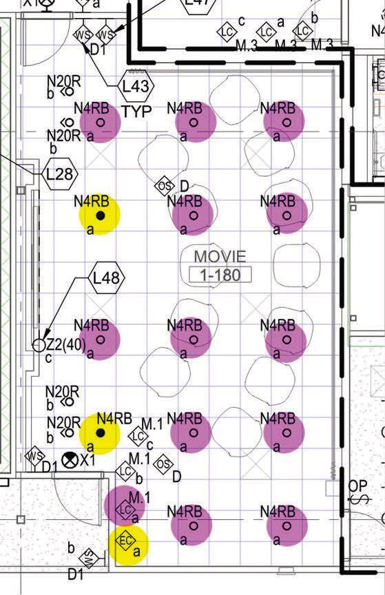
Additionally, several lighting control system manufacturers offer proprietary solutions. Though each manufacturer’s solution is unique, it’s critical to verify that each component is individually UL924 listed and that the overall system meets International Building Code (IBC) and NFPA performance requirements.
Based on the revised UL language, these devices can be tricky to specify and confusing to evaluate during the submittal review process. Following is a strategy to assist the design and construction teams in providing a compliant solution:
• On the lighting plans, annotate lighting control zoning to include common control of normal and emergency lighting. Figure 2 depicts a generic example where lighting symbol subscripts indicate common zoning.
• Supplement emergency lighting control zoning with a schematic of a UL924 listed product. This diagram is useful for electrical contractors to understand the design intent and the obligation of providing individually listed products. During submittal review, this diagram is used as a basis of design for evaluation. Figure 3 depicts an example schematic.
FIGURE 2: Example of annotating common control of normal and emergency lights (zone ‘a’). Magenta highlights for normal lighting and yellow highlights for emergency lighting are provided by the author for emphasis. Courtesy: HDR, Inc.
• Understand how UL Standard 924 has updated its product listing requirements consistent with well adopted codes and standards.
• Learn how control manufacturers are meeting these requirements and ensuring products are individually listed and labeled.
• Identify a specification strategy for controlling emergency lights is overviewed.
csemag.com
u The evolution of lighting controls has streamlined energy efficiency and safety in buildings, integrating emergency lighting systems with modern technology to enhance both functionality and aesthetics.
u While traditional methods like continuously illuminated "night lighting" have been effective, contemporary lighting control systems offer more sophisticated solutions.
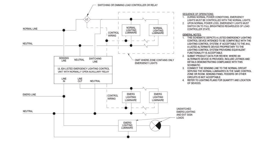
NEC article 700.26 permits listed controls to automatically energize emergency lighting upon loss of normal power. This practice is common and
24_002817_Consulting_Specifying_Engineer_MAY_JUN Mod:March18,20243:15PM Print: 03/22/24 3:27:35 PM page 1 v7


FIGURE 3: Example UL924 listed ELCD schematic. A sequence of operation and clarifying notes reinforce a code compliant design intent. Courtesy: HDR, Inc.
familiar among lighting control system manufacturers, electrical contractors and inspectors. Each lighting control manufacturer’s solution varies from localized ELCDs to systemic “head-end” strategies, either wired or wireless. Of concern is each product’s UL labeling and compliance with the emergency lighting performance requirements described in the IBC and NFPA 101.
Some manufacturers rely on a “phase loss” device that monitors normal utility or panelboard power and transmits a signal to activate a system-


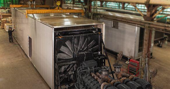


ic emergency override sequence. In these systems, if a normal phase becomes disconnected due to a fault or utility outage, designated “emergency” relays are automatically latched closed and any dimming is reset to full output or other preprogrammed level.
Previous UL 924 language permitted these lighting control systems, “phase loss” devices and “emergency” relays to be individually listed because UL’s previous requirement to monitor normal power was interpreted as normal utility or panelboard power. Though previously compliant for UL, this “head end” monitoring disregards potential faults at a branch circuit, posing a safety hazard. Additionally, this strategy does not meet the emergency lighting system performance requirements described in NFPA 101 and by the IBC since normal power serving individual spaces is unmonitored. The updated UL requirement for ELCDs to monitor the “branch circuit associated with its controlled loads” aligns product listing requirements with these other IBC and NFPA requirements.
Lighting control system manufacturers have been forced to react by removing the UL924 listing from their systems where the associated normal branch circuit is not monitored. However, these systems remain marketed as having been evaluated by UL or meeting the intent of UL924 without specific listing or labeling, which can be misleading and confusing. Regardless, to meet the NEC, each device controlling emergency lighting must be listed and labeled by a nationally recognized testing laboratory such as UL.
Continuously illuminated “night lighting” has been a tried-and-true method to meet the IBC and NFPA emergency lighting requirements. Fortunately, modern lighting control systems can incorporate ELCDs capable of synchronizing normal and emergency lighting control for improved aesthetics, efficiency and user experience. Revised language in UL Standard 924 adds specific list-
ing requirements for ELCDs to monitor normal lighting branch circuits, not the overall utility or panelboard. Specifiers should carefully evaluate their application’s emergency lighting control strategy to verify each component controlling
emergency lighting is UL924 listed and labeled, and the overall performance meets IBC and NFPA requirements. cse
Eric Rushenberg, Sr. Lighting Designer, HDR, Omaha, NE


Electrical bearing damage causes unplanned downtime
Variable frequency drives (VFDs) are used to control pumping systems. But VFDs create a motor shaft voltage that discharges through the bearings, blasting millions of pits in bearing surfaces. Both motor and pump bearings are at risk. These discharges oxidize the bearing grease and cause bearing uting, premature failure, and costly downtime.


Protect motor bearings with AEGIS® Shaft Grounding Rings
By channeling VFD-induced discharges safely to ground, AEGIS® Shaft Grounding Rings prevent electrical bearing damage. Proven in millions of installations worldwide, AEGIS® Rings provide unmatched protection of motors against electrical bearing damage, motor failure, and unplanned downtime.


Tyler Mobley, PE, Mobley Fire Protection Engineering LLC, Dallas
Pressure-regulating devices are required to maintain safe system working pressures
Water-based fire protection systems often require pressure-regulating devices to limit pressure on system components. Pressure limitation is necessary to prevent the failure of system components and to assure proper system performance. The 2019 editions of NFPA 13: Standard for the Installation of Sprinkler Systems and NFPA 14: Standard for the Installation of Standpipe and Hose Systems define a pressure-regulating device as:
“A device designed for the purpose of reducing, regulating, controlling or restricting water pressure.”
NFPA 13 and NFPA 14 also specify the pressure limitations within the respective systems.
There are three common types of pressure-regulating devices, including pressure-restricting valves, pressure-reducing valves and pressure-relief valves. Each valve type has different uses and means of operation.
Pressure-restricting valves reduce downstream water pressure in flowing conditions only. For instance, if a pressure-restricting hose valve is set to a maximum pressure of 100 psi, the downstream pressure while water is flowing will be limited to 100 psi. However, if water stops flowing, the downstream pressure could increase beyond 100 psi, depending on the system’s static working pressure.
Learningu
• Types of pressureregulating devices and their applications.
• Understand how to properly implement pressure-regulating devices into a system design.
• Incorporating pressureregulating devices in hydraulic calculations.
NFPA 13 requires automatic sprinkler system components to be rated for no less than 175 pounds per square inch (psi) or rated for the maximum system working pressure the components are exposed to, whichever is greater. Most automatic sprinkler system components are rated for a maximum pressure of 175 psi, especially sprinklers.
NFPA 14 requires standpipe systems to be limited to a maximum working pressure of 400 psi and express mains are permitted to have pressures more than 400 psi. However, hose connection (valve) outlet pressures cannot exceed 175 psi.
Successful system pressure regulation requires selection of the appropriate device type for the application, accurate design implementation and proper installation and testing to verify functionality and performance.
Pressure-reducing valves reduce downstream water pressure when water is flowing and when water is not flowing. For example, a pressurereducing valve installed at the base of a sprinkler system riser would limit the water pressure on the sprinkler system to the valve’s set pressure during normal (no flow) conditions and while water is flowing due to a sprinkler activation.
There are two common types of pressure-reducing valves, nonpilot operated and pilot-operated. Nonpilot-operated valves are typically limited to lower flow rates and have a significant residual pressure drop between the valve inlet and outlet.
Pilot-operated valves often referred to as pressure control valves, are suitable for a wide range of flow rates, depending on the valve size selected. Pilot-operated valves maintain the set pressure downstream of the valve with minimal residual pressure loss through the valve when the inlet pressure drops below the set pressure.
When selecting a pilot-operated pressure reducing valve that will serve multiple flow scenarios, the valve must be capable of supporting the lowest
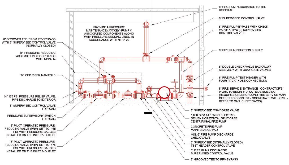
and greatest flow rates (e.g., flow of one sprinkler to greatest system design flow demand) or a bypass must be provided with a pressure-reducing valve capable of supporting the lower flow rates.
Pressure-relief valves relieve pressure from a system by discharging water from the system. These valves are only permitted in systems as a fail-safe device typically used to relieve unanticipated excess pressure, such as pressure increases due to thermal expansion or a diesel-driven fire pump runaway scenario. A runaway scenario is an instance resulting in unintended high engine speeds causing excess output pressures.
The following describes the applications where a pressure-regulating device is required and considerations for compliant implementation.
Automatic sprinkler systems: NFPA 13 requires every wet pipe automatic sprinkler system to have a minimum ½-inch pressure-relief valve set to oper-
‘ There are three common types of pressure-regulating devices, including pressure-restricting valves, pressure-reducing valves and pressure-relief valves. ’
ate at 175 psi, or 10 psi greater than the maximum system working pressure, whichever is greater. The relief valve must be installed in the system downstream of the system check valve. Alternatively, an auxiliary air reservoir installed to absorb system pressure greater than 175 psi is permitted in lieu of a pressure-relief valve.
Automatic sprinkler systems supplied from a source with a pressure exceeding the listed pressure rating of system components must be provided with a pressure-reducing valve to maintain the system pressure. As mentioned previously, automatic sprinkler system components are typically listed for
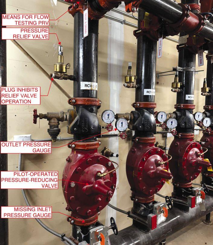
a working pressure of 175 psi. Therefore, NFPA 13 requires the outlet pressure of the pressure-reducing valve to be set to a maximum pressure of 165 psi.
In addition, when a pressure-reducing valve is installed in an automatic sprinkler system, NFPA 13 requires the following:
• A pressure gauge must be installed on the inlet and outlet of each pressure-reducing valve. In most cases, the sprinkler system pressure gauge downstream of the pressure-reducing valve satisfies the need for the pressure gauge on the outlet side, but a pressure gauge dedicated to the inlet side must be installed.
• A minimum ½-inch pressure-relief valve is required downstream of the pressure-reducing valve and must be set to operate at a maximum pressure not exceeding the rated pressure for the system components (e.g., 175 psi). Also, the relief valve must be installed upstream of the system
components requiring protection from excess pressure. The discharge of the relief valve should be piped to an acceptable drain. Refer to the pressurereducing valve manufacturer for recommended relief valve sizing that may exceed the requirements of NFPA 13.
• An indicating control valve is required on the inlet side of each pressure-reducing valve. If the pressure-reducing valve satisfies the listing requirements for an indicating control valve, an indicating control valve is not required on the inlet side of the pressure-reducing valve.
• A means for testing the pressure-reducing valve at the system demand flow rate shall be provided downstream of the pressure-reducing valve.
Standpipe systems: Pressure-regulating devices are commonplace in standpipe systems serving high-rise buildings. This is due to the system pressure demands necessary to deliver water to the remote highpoints of a system at the required minimum operating pressure.
Often, the required system working pressure at grade level must exceed 175 psi to provide 100 psi at the highest hose connection. Per the standard, 100 psi is the required discharge pressure at hose connections in Class I standpipe systems. Consequently, the excess pressure must be controlled to safeguard the system components on the lower levels.
Every standpipe application should be evaluated for the best means of controlling the system pressures. There is no one-size-fits-all approach. Depending on the water supply and system configuration, one or any combination of the following would be applicable to limit pressures at hose valves to less than or equal to 175 psi:
• Pressure-reducing hose valves on the level(s) subject to pressures exceeding 175 psi.
• A pressure-reducing valve upstream of no more than two hose valves on the level(s) subject to pressures exceeding 175 psi.
• A pressure-reducing valve assembly (PRVA), in accordance with NFPA 14 Section 7.2.4 (2019 edition), where serving more than two hose valves. Pressure-restricting hose valves are limited to applications where the pressure does not exceed 175 psi, but the downstream pressure needs to be restricted to a lower pressure. For instance, an applicable use is in Class II or Class III stand-
pipes with 1½-inch hose valves available for use by trained personnel. The hose valves must limit the outlet residual pressure to 100 psi.
NFPA 14 defines the requirements for implementing pressure-regulating devices in standpipe systems, including:
• The pressure-regulating device shall be approved for the minimum and maximum flow rates anticipated and shall be rated for the greatest anticipated inlet pressure. Also, the device shall be capable of limiting the static (no flow) and residual pressures to 175 psi. The manufacturer product data sheets define the approved flow ranges and pressure ranges for specific devices.
• A valved outlet for a pressure gauge must be provided on the inlet and outlet of each pressureregulating device. Annex A of NFPA 14 states that permanently affixed gauges are not required. Rather, a valved outlet must be provided on each side of the valve that permits easy installation of gauges necessary for testing the respective device.
• Each standpipe with pressure-regulating devices shall have a permanent drain riser located adjacent to the standpipe. The drain must be sized to accommodate the full flow required from the pressure-regulating device. Minimum 3-inch diameter drain piping is required for 2½-inch devices and drain piping that serves larger devices must be equal to the discharge outlet of the device. Test connections, of the same size as the device discharge outlet, are required on at least every other floor. The test connections must be equipped with internal threaded swivel fittings having National Hose Standard threads with plugs.
A PRVA, in accordance with NFPA 14 Section 7.2.4 (2019 edition), can be used near the water source (e.g., downstream of the fire pump discharge control valve) to limit pressure downstream while avoiding the need for additional pressure-regulating devices at hose valves and sprinkler system floor control valve assemblies. The PRVA is beneficial for applications that have a water supply capable of supplying the system demand without the residual pressure exceeding 175 psi, but the static (no flow) system working pressure exceeds 175 psi. In short, the PRVA would be used to control the static (no flow) pressure below 175 psi. Another useful application is using a PRVA to create standpipe systems with multiple pressure zones (e.g.,
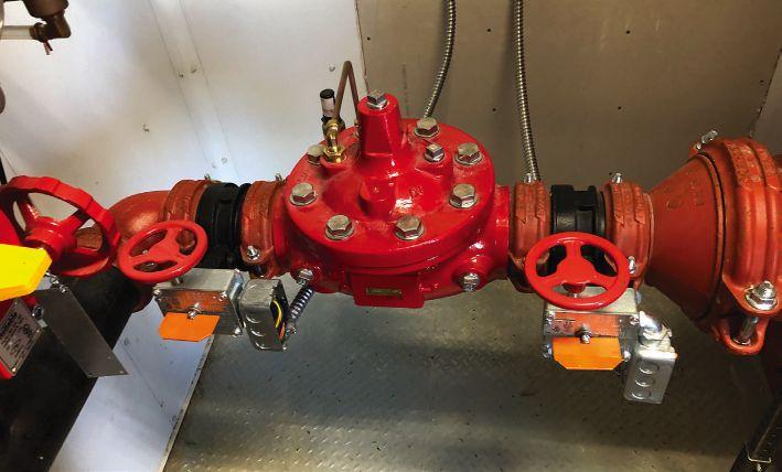
high-pressure zone for upper levels and low-pressure zone regulated for lower levels).
A compliant PRVA includes:
• Two pressure-reducing valves installed in series to provide redundancy assuring pressure downstream does not exceed 175 psi in the event one pressure-reducing valve fails. Most pressure-reducing valves require a minimum differential pressure, depending on the valve manufacturer. A common differential pressure is 10 psi. For instance, if the desired pressure downstream is 175 psi then the inlet pressure must be no less than 185 psi. Therefore, to prevent exposing system components to pressures exceeding 175 psi where the static (no flow) pressure is 190 psi, the first pressure-reducing valve, in series, must be set to 175 psi and the second pressure-reducing valve, in series, must be set to 165 psi. This configuration would limit the pressure downstream to 175 psi, in the event a valve fails and permits the second valve to operate correctly.
FIGURE 3: Pilot-operated pressure-reducing valves for an automatic sprinkler system. Courtesy: Mobley Fire Protection Engineering LLC
‘ NFPA 14 defines the requirements for implementing pressure-regulating devices in standpipe systems. ’
• The pressure-reducing valves shall be installed with means to isolate either pressure-reducing valve for maintenance, replacement or repair. Typically, each pressure-reducing valve is provided with indicating control valves installed on the inlet and outlet sides of the pressure-reducing valve.
• Piping shall be configured to permit water to bypass either of the pressure-reducing valves in the
‘ NFPA 20: Standard for the Installation of Stationary Pumps for Fire Protection defines when and where pressure-regulating devices are permitted in a fire pump system.
event any one or both pressure-reducing valves are isolated for service. The bypass must have a pipe diameter equal to the pressure-reducing valve piping. Normally closed indicating control valves are required in the bypass piping used to divert flow around the pressure-reducing valves.
• A pressure gauge must be installed on the inlet and outlet of each pressure-reducing valve.
• A supervisory high-pressure switch, supervised by the building fire alarm system, must be installed downstream of each pressure-reducing valve.
• A pressure-relief valve is required downstream of each pressure-reducing valve and shall be sized in accordance with the pressure-reducing valve manufacturer’s recommendations. Manufacturer recommended sizes range from ¾- to 3-inch diameter.
• The fire department connection shall be connected to the piping downstream of the PRVA.


Fire pumps: NFPA 20: Standard for the Installation of Stationary Pumps for Fire Protection defines when and where pressure-regulating devices are permitted in a fire pump system. A pressure-regulating device is only permitted in the fire pump system for limited applications. However, this does not prohibit a pressure-regulating device described above in the automatic sprinkler systems and standpipe systems sections from being installed downstream of the fire pump discharge control valve.
There are two scenarios where a pressure-relief valve is required between the fire pump discharge flange and discharge check valve, including:
• Diesel engine-drive fire pumps with a discharge pressure at 121% of the rated churn pressure exceeds the rated pressure for the system components (e.g., 175 psi). The pressure-relief valve should be set at or below the rated pressure of the system components.
• Variable speed electric-driven or pressure limited diesel-driven fire pumps with a maximum discharge pressure at the rated churn pressure exceeds the rated pressure for the system com-


ponents (e.g., 175 psi). The pressure-relief valve must be set to 10 psi above the set pressure of the pressure limiting control.
Fire pump pressure-relief valves shall be designed and installed in accordance with NFPA 20 Section 4.20 (2019 edition).
Careful consideration should be given to hydraulic calculations incorporating pressure-reducing valves. Calculations must be performed to assure the system pressures are satisfactory at no flow, minimum flow and maximum flow conditions. The following provides key considerations when calculating systems using pilot-operated pressure-reducing valves and nonpilot-operated pressure reducing valves.
Pilot-operated valves: Hydraulic calculations must be evaluated for each design scenario downstream of the pilot-operated pressure-reducing valve to understand the pressure available at the inlet of the pressure-reducing valve for the various design scenario flow rates.
The design scenarios resulting in valve inlet pressures below the set pressure must account for the friction loss through the pressure-reducing valve. The friction loss is manufacturer specific and dependent on the flow rate through the valve. The selected valve’s technical data must be consulted for the required friction loss.
On the other hand, the design scenarios resulting in valve inlet pressures exceeding the set pressure require the pressure loss through the valve to equal the difference between the valve inlet pressure and the set pressure. For example, if the valve inlet pressure for the design scenario is 205 psi and the valve is set to 165 psi, then the pressure loss through valve is 40 psi.
Nonpilot-operated valves: Standpipe systems using nonpilot-operated pressure reducing hose valves and control valves must be evaluated for multiple scenarios to understand the available inlet and outlet pressure for each valve in the system. There are significant pressure drops between the valve inlet and the valve outlet depending on the available inlet pressure. The pressure drop across
u Water-based fire protection systems rely on pressureregulating devices to prevent component failure and ensure proper performance by limiting pressure.
u These devices, such as pressure-reducing valves and pressurerelief valves, are crucial for maintaining safe pressure levels within automatic sprinkler and standpipe systems, as dictated by standards like NFPA 13 and NFPA 14, especially considering the varying flow conditions and system demands.


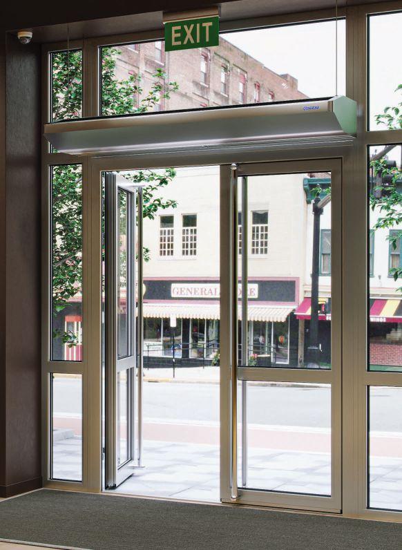
‘ Careful consideration should be given to hydraulic calculations incorporating pressure-reducing valves. ’

the valve is not constant. Instead, the pressure drop varies for different design scenarios, as the valve’s inlet pressure changes.
A common application is a standpipe system employing multiple nonpilot-operated hose valves. The system must be calculated to determine the pressures required (demand) and available while the system is flowing the total system demand (e.g., 1,000 gallons per minute, or gpm) and the minimum required flow rate (e.g., 250 gpm). The hydraulic calculations must be used to determine the appropriate pressure-reducing hose valves capable of maintaining the downstream pressure at or below 175 psi for both flow rates while providing the required design flow rates and pressures.
There are unique standpipe system configurations that have nonpressure-reducing (standard) hose valves at the hydraulically most remote point of the system and pressure-reducing hose valves one to two levels below. Because the nonpilot-operated pressure-reducing valves have a significant pressure loss, the most remote hose valve may not be the most hydraulically demanding hose valve.
Therefore, standpipe system demand calculations must be performed using the most remote standard hose valve and another calculation using the most remote pressure-reducing hose valve to confirm the system’s greatest demand.

Pressure-regulating devices are an essential component of water-based fire protection systems necessary for safeguarding system components from excess pressures. It is critical that system engineers and engineering technicians carefully select the appropriate device type best suited for each application and thoroughly understand the requirements for the design application and the device selected.
Not mentioned in this article, however equally important, is the need to test pressure-regulating devices in accordance with the applicable standards. cse
Tyler Mobley, PE, is Principal/Fire Protection Engineer at Mobley Fire Protection Engineering LLC. He is a multifaceted fire protection engineer with extensive experience in fire and life safety systems engineering and consulting.
FOR ALL YOUR PRESS FITTING AND VALVE NEEDS
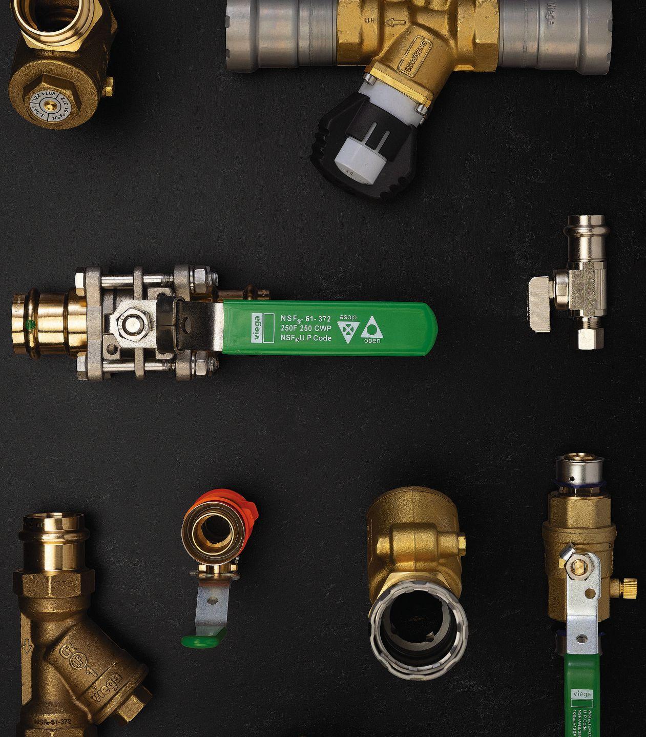
Check out the new additions to the industry-leading ProPress®, MegaPress® and PureFlow® systems. Engineered with the same press technology you trust in our fittings, our new valves can be pressed with the same tool.


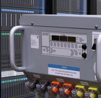
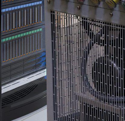

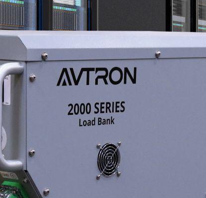
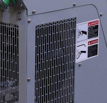


In this Roundtable, experts answer common questions about the challenges and considerations of designing data centers in our highly connected world
CSE: What are some current trends in data centers?
Amanda Carter: Current trends in data centers include developing new approaches to on-site power distribution as utility capacity is becoming more difficult to acquire, whether it is limited by utility timelines for expansion or a utility simply not having available capacity to support the ever-increasing power requirements of data center facilities. These increasing power requirements are largely driven by the data center industry's response to artificial intelligence (AI) and other developing technologies that require more and more computing power.
William Kosik: In the data center developer space there is a drive to increase power density, decrease cost and increase speed to market. We are currently working on projects, either in design or construction, that are nearing 100 milliwatts (MW) for the facility. We are also developing concepts for data center facilities that are far beyond 100 MW.
Brian A. Rener: Higher Density, water-cooled high-performance computing (HPC) and AI machines are now becoming main stream. Previously these were utilized only in national labs, universities and research facilities.
CSE: What future trends (one to three years) should an engineer or designer expect for such projects?
Amanda Carter: In the near future, look for the optimization of power distribution, whether that means extending medium voltage distribution interior to the data center facility or streamlining the overall distribution from substation to server. There will also be a continued embrace of cooling technologies, such as liquid cooling and coolant distribution units, as the servers require higher power input for increasing computing requirements.
Brian A. Rener: We are already seeing significant increase in demand for both power and water, which will only accelerate in the next one-three years. Some forecasts warn of significant impacts to electrical grid supply from growth in the data center market. Various leading organizations are working on ways to reduce this demand including grid interactive battery energy storage systems (BESS) and evolution of the use of new generation small modular nuclear reactors.
William Kosik: Current hyperscaler data centers use 200 to 400 watts per square foot for the data halls. To provide power and cooling for those loads, highly effective and energy efficient methods of
•


Chicago Brian A. Rener, PE, LEED AP
Mission Critical Leader
Smith Group Chicago


cooling are required, including the use of fan walls and liquid cooling.
CSE: What types of challenges do you encounter for these types of projects that you might not face on other types of structures?
William Kosik: There two important issues: these data centers are electrically dense and are extremely large in physical size and scale. Based on the site, especially urban locations, the buildings will have multiple floors to provide data hall space and power to the tenants. The scale of the facilities also requires dozens of chillers, cooling towers, computer room air handler units and more.


Turn


Control
Data centers have never been more strategic or critical than they are today. They have also never faced greater scrutiny regarding efficiency, availability and flexibility. As your data center evolves, we’re here to help you operate with optimized performance at every stage of the lifecycle. Connect
Delivers
Ensures peace of mind and helps enable continuous operations around the clock, and around the globe.


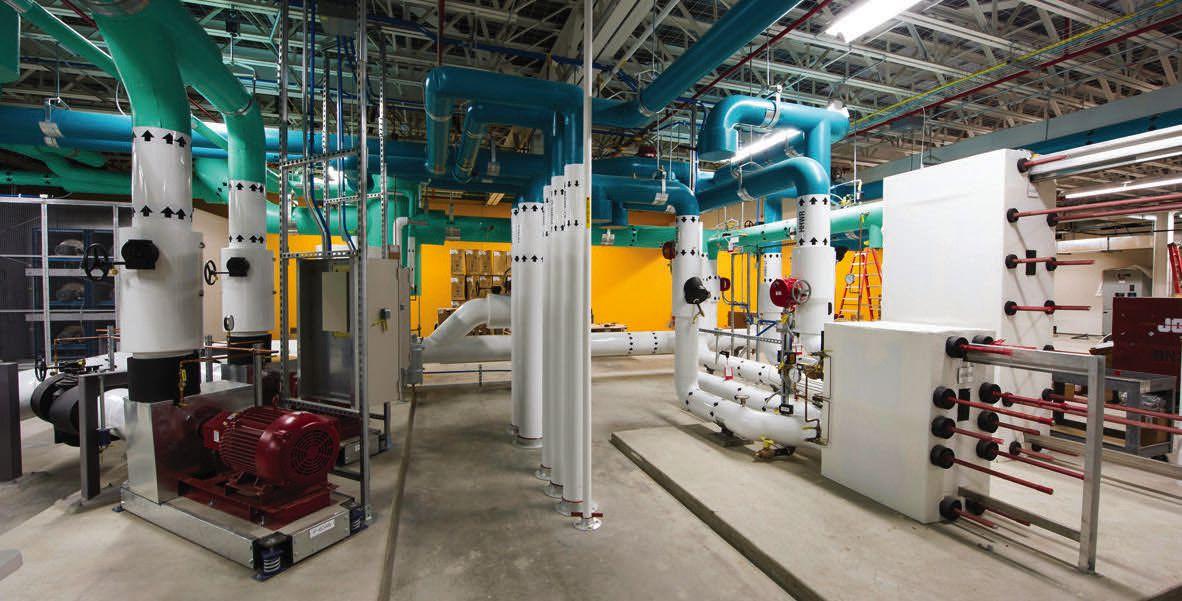
FIGURE 1: Example of heat recovery system at National Renewable Energy Labs ESIF HPC data center. Courtesy: SmithGroup.
Amanda Carter: Data center campuses often have power requirements that rival some small towns. Distributing this large amount of power across fairly compact sites, while also coordinating with other underground utilities, can require a great deal of focus and attention to minute details. And that's before even entering the building. At building entry, there is extensive coordination with structural and architectural partners to coordinate either routing under the building structure or routing attached to and then penetrating the building envelope. If routing underground, extensive Neher-McGrath calculations are required to ensure the feeders aren't operating at a temperature that would exceed their insulation rating. Unlike commercial facilities, data centers often run at a load factor close to 1.0. In addition, a data center electrical room is often dense with various electrical equipment, making coordination with mechanical counterparts imperative to ensure operating temperatures are maintained and heat rejection is properly accounted for.
CSE: Describe a co-location facility project. What were its unique demands, and how did you achieve them?
Amanda Carter: A co-location facility is a data center facility that is designed for lease to outside tenants. They are unique to enterprise or hyperscale facilities because they require maximum flexibility to respond to a future tenant’s requirements. Sometimes the tenant is known, and provisions are made for their specific needs, but often the facility is built before a tenant is under contract. Therefore, flexibility is built in by designing the data hall white spaces in blocks that include many levels of redundancy and the ability to parcel the spaces as required.
Tell us about a recent project you’ve worked on that’s innovative, large-scale or otherwise noteworthy. Please tell us about the location, systems your team engineered, key players, interesting challenges or solutions and other significant details.
Brian A. Rener: We are currently engaged in a high-performance computing facility for the Department of Energy in Virginia. The facility will be deploying the latest generation Exascale computers requiring over 300KW per rack and water to chip cooling plates. This amount of power and cooling density requires careful planning for the infrastructure and distribution within the data center to the racks.
William Kosik: In some cities in the United States, water use and sewer discharge are scrutinized heavily during the initial design phases. The municipalities require detailed studies on annual water use and sewer discharge, including peak monthly flowrates. On a recent project, the municipality had a grey-water system that was used for makeup water to the cooling equipment. The data center was required to have on-site water storage for the makeup water system in case of a low-flow condition from the municipality’s grey-water system.
CSE: How are you preparing for future phases of data center operation? How do you specifically address this challenge when the first phase is still operational?
Amanda Carter: For a co-location data center, the facility is specifically designed to be built in phases. One way this is done is by using modular electrical rooms that can be installed on skids or in prefabricated structures that sit just outside of the data center building. This allows for a plug-and-play approach to the phasing and expansion of the facility as the space is leased out. For hyperscale data centers, phasing is often done on a building-by-building approach instead of a data hall-by-data hall, which accounts for future phases through utility planning for future expansion. Underground utilities are prepared and terminated at or near future phases, and head-end services like substations and water service are sized upfront for future capacity.
Brian A. Rener: Good engineering design for data centers includes infrastructure that is concurrently maintainable. This approach also allows for phased future growth and buildout without interrupting currently operating data halls. Typical features include N+1 distribution lines, and taps for additional infrastructure and equipment. cse

AGF Manufacturing, Inc .49 .www .agfmfg .com
Avtron Power Solutions .52 .www .avtronpower .com
BELIMO .C-2 www .belimo .com
BERNER AIR CURTAINS .50 .www .Berner .com
Carrier .54 .www .carrier .com/datacenters
CDM Smith .56 .www .cdmsmith .com/en
CHAMPION FIBERGLASS .48 .www .championfiberglass .com
Cummins .C-4 www .cummins .com
Eaton .6, 20 .www .Eaton .com/microgrid
Electro Static Technology Inc .43 .www .est-aegis .com/resources/case-studies
Greenheck .1 .www .greenheck .com
Hammond Power Solutions .4 .www .hammondpowersolutions .com
Industrial Cybersecutiy Pulse .21 .WWW .ICSPULSE .COM
Metraflex .32 .www .metraflex .com
Miura North America, Inc .33 .www .miuraboiler .com
Pritchard Brown .42 .WWW .PRITCHARDBROWN .COM
Rheem Commercial Air .2 .www .RheemCommercial .com
Tjernlund Products .56 .www .tjernlund .com
ULINE . . . . . . . . . .42 .www .uline .com
Viega LLC . . . . . . . .51 .www .viega .us/valves Yaskawa America, Inc .C-3 www .yaskawa .com

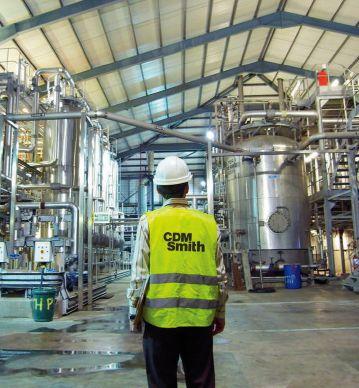

VP Sales
Matt Waddell
Sales Account Manager
MWaddell@CFEMedia.com 312-961-6840
Brian Gross BGross@CFEMedia.com 847-946-3668
Sales Account Manager
Dick Groth RGroth@CFEMedia.com 774-277-7266
Sales Account Manager
Diane Houghton DHoughton@cfemedia.com 508-298-9021
Sales Account Manager
Robert Levinger RLevinger@CFETechnology.com 516-209-8587
Sales Account Manager
Dean Morris 513-205-9975 DMorris@cfemedia.com
Sales Account Manager
Judy Pinsel 847-624-8418 JPinsel@cfemedia.com
Sales Account Manager
Mike Worley MWorley@CFEMedia.com 331-277-4733
Jim Langhenry, President, Co-Founder, CFE Media JLanghenry@CFEMedia.com
Steve Rourke, Co-Founder, CFE Media SRourke@CFEMedia.com
Patrick Lynch, CEO, CFE Media 847-452-1191, PLynch@cfetechnology.com
McKenzie Burns, Marketing-Events Manager MBurns@cfemedia.com
Courtney Murphy, Marketing and Events Manager CMurphy@cfemedia.com
Paul Brouch, Director of Operations 708-743-5278, PBrouch@CFEMedia.com
Rick Ellis, Audience Management Director 303-246-1250, REllis@CFEMedia.com
Michael Smith, Creative Director 630-779-8910, MSmith@CFEMedia.com
Michael Rotz, Print Production Manager 717-422-3622, mike.rotz@frycomm.com
Custom reprints, print/electronic: Paul Brouch, PBrouch@CFEMedia.com
Jeff Mungo, List Rental Account Director, DataAxle 402-836-6278, Jeff.Mungo@data-axle.com
Information: For a Media Kit or Editorial Calendar, go to www.controleng.com/mediainfo.
Marketing consultants: See ad index
Letters to the editor: Please e-mail us your opinions to MHoske@CFEMedia.com or fax 630-214-4504. Letters should include name, company, and address, and may be edited.


HV600 drives and packages are available in a variety of styles and enclosures to meet all your HVAC requirements:
Electronic bypass and configured packages are offered in space-saving Narrow or option-rich Enclosed designs with an array of power and control options in a “right-size” package design, allowing you to customize a package to suit your application needs. “right-size”


What type of conditions are you looking to meet? Call Yaskawa at 1-800-927-5292 today.


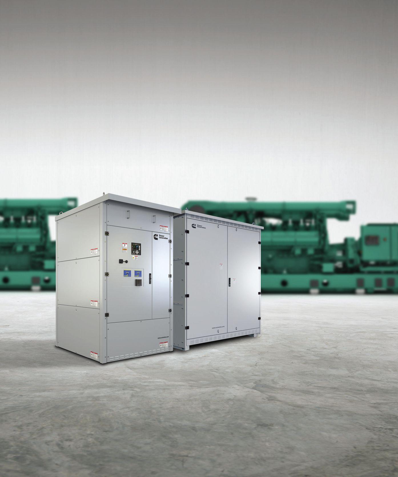
Cummins PowerCommand® X-Series and B-Series Bypass Isolation Transfer Switches
More than one product, with Cummins, you’re backed by more than 80 years of experience in power transfer control. We’re with you every step of the way in your power journey, offering unrivalled peace of mind.
Discover the strength of Cummins Cummins.tech/csemay