
14 minute read
Design Notes
How to handle tasks with contactless energy and data transfer
Edited by Mike Santora • Associate Editor
Besides saving space, the use of single-cable technology reduces cabling outlay and the weight of the overall solution.
Although robotic
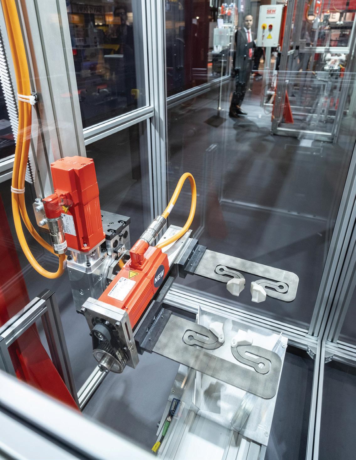
systems are sometimes limited by automation constraints and drive technology, this issue can be easily minimized. Application-specifi c automation om a single source enables machine builders to develop new, commercially benefi cial solutions for customers. To demonstrate, consider the case of a gantry robot that uses contactless energy and data transfer instead of fi xed wiring runs and cable carriers.
Gantry robots are a time-tested solution for intralogistics material fl ows within a machine or application. They are commonly used to detect products automatically, grip them securely and quickly, and take them to their destination. This type of robot is useful in many industries and can be used for various product sizes, weights, and distances. Frequently, the lengths of power and communication cables and cable carriers limit the fl exibility and adaptability of an existing machine to a new production scenario. Adding contactless energy and data transfer opens up new production scenarios and has largely consigned cables to the past. Contactless energy and data transfer combined with intelligent so ware and reliable mechatronics creates fully integrated solutions. With contactless energy transfer, multiple robots can move eely on the same horizontal stretch, greatly increasing the gantry robot application’s fl exibility. This design regularly leads to overlapping sections between robots — ultimately off ering more eedom for machine design and operations. Logistics processes of this kind would not be as easy to implement with cable carriers because of the additional area that carriers use along the length of the system. In addition, cable carriers generate noise, are subject to wear, increase inertia, and have an overall negative impact on dynamics and energy e ciency. Another benefi t of contactless energy and communication transfer is that there are no longer any restrictions regarding installation space, cable breakage, or limited cycle rates — issues all associated with cable carriers and moving cables. This is possible with

Current supply from a socket — the intelligent energy supply with the DC link bu er via doublelayer capacitor packages ensures the robots can be hooked up to a 230-volt connection.
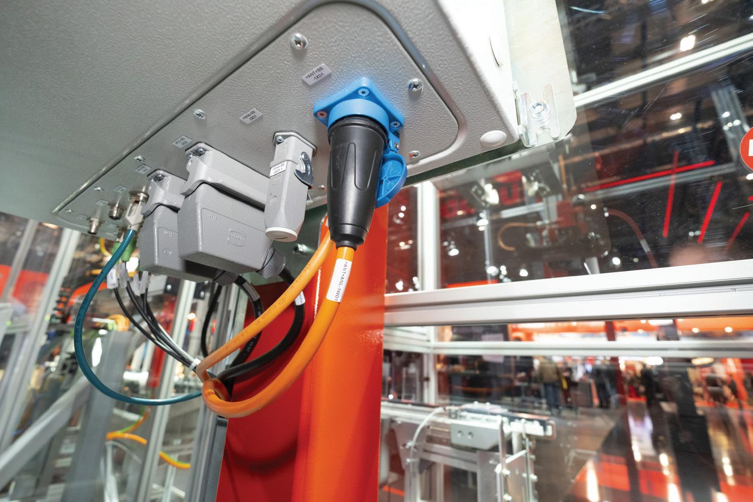

a contactless inductive energy transfer system, including a decentralized power supply module. Depending on the design, this module delivers a transmission power of between 5 and 11 Hp. Throughout the entire load cycle, the robot consumes less than 0.7 Hp via the pick-up — even though the horizontal axis alone requires more than 5 Hp of acceleration power during acceleration. The short-term energy requirements are met by the energy storage unit, a double-layer capacitor package that takes care of the primary energy supply to the robot with a DC link voltage of 100 V. The typical travel profi les of a gantry robot, which involve alternating acceleration and braking phases, led to the idea of retaining the regenerative energy generated during braking within the process instead of dissipating it via resistors. The energy storage unit absorbs this braking energy and functions as a booster when the gantry’s drives accelerate at 20 / s2. The design is so eff ective that the contactless energy transfer and storage solution only has to compensate for the system’s mechanical e ciency losses, which amount to around 0.7 Hp. Unlike the familiar DC link connection of multiaxis applications located in the central control cabinet, each unit can store energy independently. The robot gantry’s contactless energy transfer system eliminates the need for restrictive cables and extends to the communication processes. In this context, an EtherCAT data light barrier transfers the interpolated position setpoints om the central motion controller to the four servo inverters in the moving housing box at 1 ms intervals.
MAXOLUTION machine automation forms part of SEW EURODRIVE’s strategy to implement applications tailored precisely to the requirements of specifi c sectors.
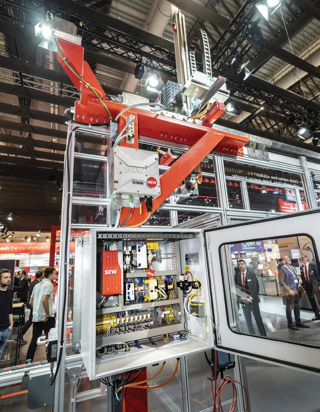
A motion controller calculates the complex robot motion control — and can do so for up to four robots at once. Motion control involves performing calculations to prevent collisions and coordinating the robots to achieve a productive system. If a machine in a production network requires double the material fl ow output, the gantry system gives users the option to move a robot om another section on a fl exible basis. Handling units that draw their power with cables, in contrast, are tied to their section. As a result, the associated resources become movable, and systems as a whole are more
Design Notes
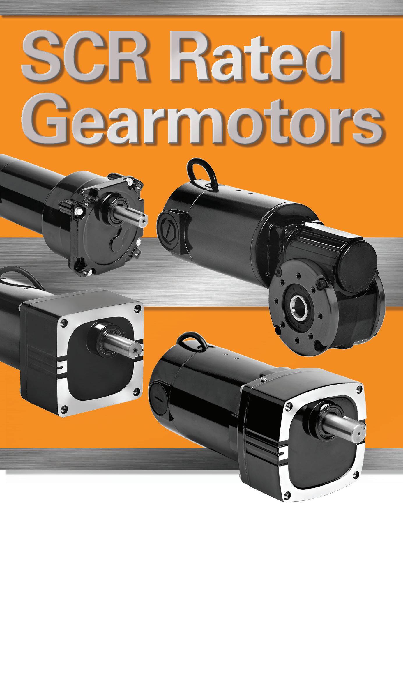
IN STOCK NOW!


Over Eighty 90V and 180VDC PMDC Gearmotors. SCR Speed Control Compatible.
With maximum rated armature speed of 2500 rpm, Bodine SCR rated gearmotors provide reliable performance, adjustable speed, and quiet operation. These new stock models can replace gearmotors sold by Baldor, Bison Gear, Leeson, or Grainger.
Visit our website: bodine-electric.com In the MOVI C automation
controller, data from the FSoE (Fail Safe over EtherCAT) master is routed and mapped to the relevant robot axes.
fl exible and productive. Engineers can create new machine concepts based on this approach. The demands placed on communication are correspondingly high as well. The automation provider opted to use the real-time Ethernet protocol EtherCAT in the gantry — again dispensing with cables by adding an optical connection to the mobile units. The drive data can be delivered to the robots via data light barriers. Having separate motion controllers in each robot is a thing of the past: one does the job of running the whole robotic system. With each cycle taking 1 ms, the optical system has practically no latency periods when transmitting the interpolated position setpoints to the inverters or feeding back the relevant actual values. Communication for safety technology works in the same way. For this application, a central safety controller for all robots and the machine as a whole was selected. This safety controller communicates directly with the MOVI-C automation controller via EtherCAT using the EtherCAT FSoE (Fail Safe over EtherCAT) protocol. This setup enables both controllers to share data with ease, simplifi es programming, and off ers good conditions for diagnostics and debugging, thanks to its high information density. The seamless integration of the FSoE safety master and the EtherCAT data light barrier are integrated into a comprehensive automation solution including motors, electronics, and visualization. Working with a skilled automation provider can streamline the development process, and the newest drive technology innovations and trends can be considered. In this context, standardized interfaces play just as important a role as prepared so ware modules or application-specifi c function modules. DW
SEW-EURODRIVE seweurodrive.com
Design Notes
How to overcome micro defects for aerospace manufacturing applications aerospace manufacturing applications
Edited by Mike Santora • Associate Editor

“Measure twice and cut once” is a common expression in manufacturing, but it’s easier said than done when machining di cult materials. That’s why, when a global aerospace manufacturer sought to eliminate an entire second stage om its drilling processes while also improving hole quality, it turned to metal cutting specialists. Here, James Thorpe, global product manager at Sandvik Coromant, explains how a drill’s design is integral to producing holes with better quality.
Most manufacturers are exploring new vendor bases and products. Thus, machine shops that once specialized in a certain production area are now opening their CNC lathes and mills to a wider variety of tough and challenging materials. At the same time, manufacturers must explore new ways to increase profi ts and reduce cycle times without sacrifi cing product quality. In other words, it’s time for manufacturers to rethink how they go about making holes.
The white stuff
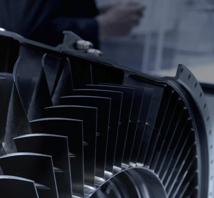
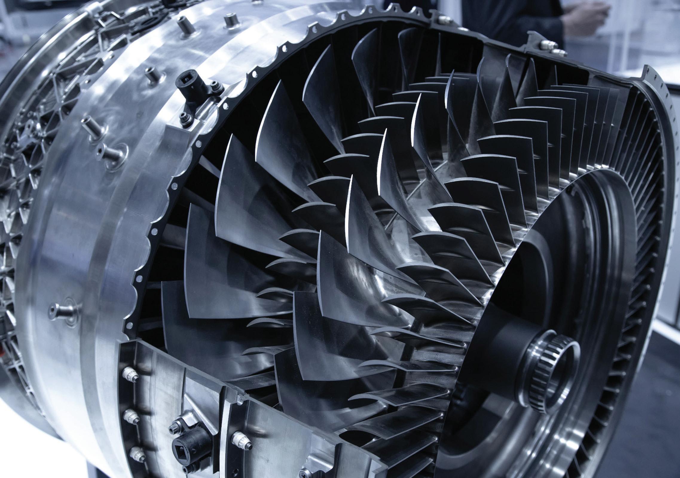
Hole surface integrity is a real concern for aerospace manufacturers or general engineering companies that want to diversi into aerospace. Better hole quality is vital for preventing component failure and is determined by the manufacturing processes used for machining or fi nishing the holes. Tooling solutions and cutting-edge geometries in drills are continually evolving to meet the highest manufacturing and part quality standards. Coolant is also being used more eff ectively for reducing heat buildup in the tool. And tests have found that each of these factors can control the so-called “white layer” eff ect on workpiece materials. An aerospace manufacturer coined the term. It refers to a thin, ultrafi ne grain structure observed a er component drilling, caused by the heat of the drill. Not only can the white layer change the surface properties of the material, but it was also deemed unacceptable in the customer’s quality management processes. The manufacturer applies a strict hole-fi nishing process to drilled holes in aerospace components, including turbine discs, compressors, drums, and sha s. That’s why it chose to partner with Sandvik Coromant to investigate why the white layer forms and how to control it.
Second act
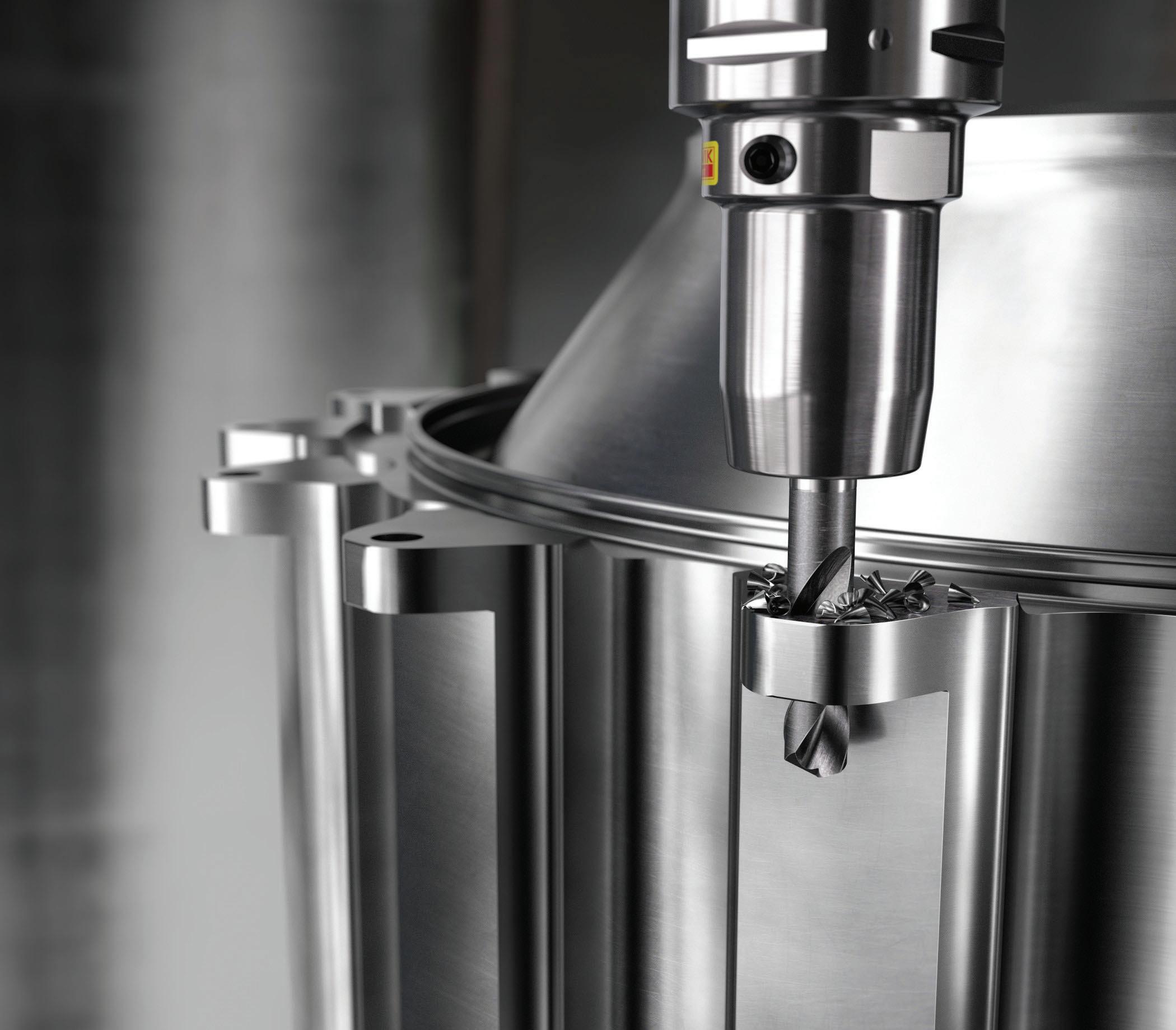
The secondary process happens a er a hole has been created with the carbide drill, and it can involve reaming, plunge, or end milling to fi nish the component. The secondary stage occurs mainly to meet surface integrity demands and reduce issues like the white layer, rather than for dimensional accuracy, except when machining holes with tight tolerances. From an overall cost perspective, the secondary process is even more expensive than maintaining low cutting data, which is the other way to preserve surface integrity. That is why the user wanted to investigate doing away with the process altogether. A supplier with a product that produces a conforming hole to size without any secondary processes can greatly reduce the cost per part. The investigation into causes and possible ways to prevent the white layer involved four tests of drilling the highstrength, nickel-chromium material Inconel 718, a popular aerospace material. It was the fi rst time any such investigation had been carried out by the user. The tests assessed drilling with two solid carbide drills, the CoroDrill R840 and CoroDrill R846. Each was run at two diff erent sets of cutting parameters, 58 mm/min and 98 mm/min, respectively, and spin speeds of 829 rev/min and 757 rev/min, respectively. Cutting force and torque data were measured throughout the tests, as was the white layer thickness. R840 has been superseded by the CoroDrill 860 with -GM geometry, and R846 has been superseded by the CoroDrill 860 with -SM geometry. Each of these tools are designed to enhance tool life without compromising hole quality. The results provided insights into what causes white layer thickness. Particularly of note was that the R846 generated less of a white layer due to





Design Notes
the preparation of its curved and radial cutting edges. Meanwhile, the straight cutting edges and chamfer imposed on the cutting edge of the R840 are believed to be linked with the increase in cutting force, torque, and white layer thickness. Therefore, the drill’s design determines whether high hole quality with a reduced white layer can be achieved without sacrifi cing cutting data. The company has also been able to eliminate some secondary processes, like reaming and plunge milling. The range includes the CoroDrill 860 with -GM (CD860-GM) geometry, designed to be a good all-rounder for drilling challenging ISO P, M, K, and H materials across all industry sectors. The CoroDrill 860 with -SM geometry (CD860-SM) is designed for machining ISO S grades like superalloys (HRSAs), titanium, and Inconel. The latter drill has proven especially popular in aerospace. With the CD860-GM and CD860-SM, Sandvik Coromant’s engineers applied the ethos that longer tool life and better hole quality come down to the drill design. The CD860-GM has a polished fl ute design that improves the evacuation of chips and yields high core strength and reduced cutting forces while drilling. The CD860-SM, meanwhile, has a new grade and optimized and refi ned point geometry, which further enhances tool life when working with di cult-tomachine HRSA materials. The result is greater hole quality. DW
Connect and discuss this and other engineering design issues with thousands of professionals online
Design Notes
Custom miniature thrust ball bearings for screw driving spindles
Edited by Mike Santora • Associate Editor

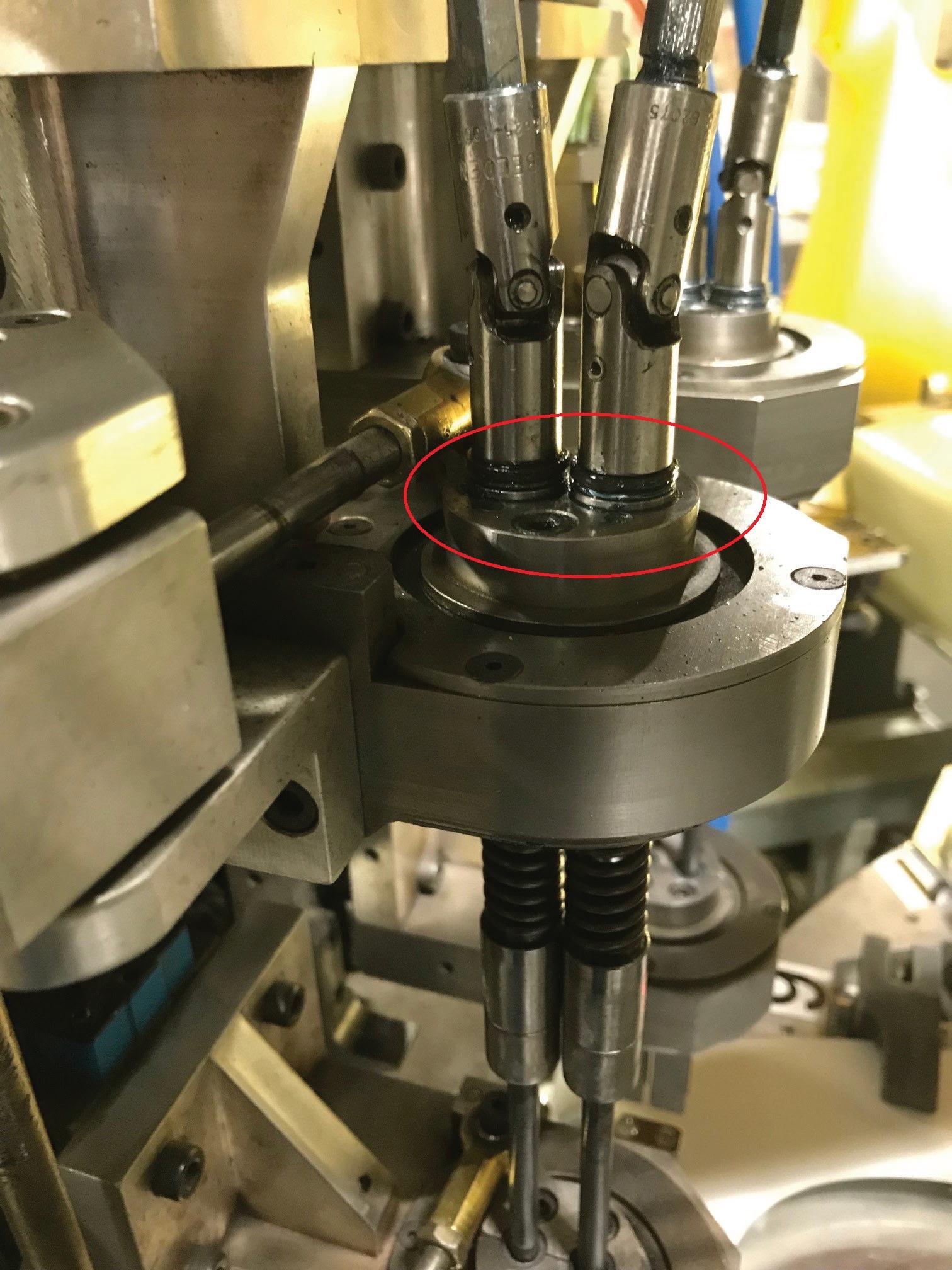
A custom screw driving equipment manufacturer had been purchasing a standard-sized miniature thrust bearing om a large bearing manufacturer for many years. The 3-piece bearing was being used in a moderate to high volume (20 to 30 bearings per month) in the custom screw driving equipment and was being replaced regularly.
Because of the bearing’s open style, it is subject to various contaminants and is di cult to keep properly lubricated. The bearings needed to be completely taken apart and lubricated on a weekly basis. With this weekly maintenance, the typical life of each bearing was three months, and at the end of its life, signifi cant wear was visible on all components of the bearing. This company chose to go to Auburn Bearing a er becoming ustrated by the loss of time and productivity they were experiencing om replacing a signifi cant amount of prematurely failing miniature thrust ball bearings. They were looking for a new solution that would extend the bearing’s life by keeping lubrication in and keeping
debris out as well as reduce the downtime and inconsistencies caused by these bearing failures. Auburn Bearing proposed a one-piece banded thrust ball bearing that would use a special lubricant. This custom design would serve to protect the bearing om debris and other contaminants as well as contain the grease inside the bearing. A er a three-month trial run using this new solution, the screw driving equipment manufacturer found that the bearing race and balls remained in excellent condition without having to perform any maintenance on them. “Frankly, I don’t pay much attention to these bearings any longer. With the new design, it has gone om a headache to a non-issue. Therefore, I would rate this a great success. Machine consistency is the biggest improvement. Also, the inability for a maintenance person to assemble the old 3-piece bearing incorrectly,” says Brett S., Engineering Manager, Bemis Manufacturing. The Auburn Bearing engineering team was able to design this custom bearing solution for the specifi c application parameters. It signifi cantly reduced operational downtime, maintenance equency, and replacement costs. Improved machine consistency by reducing bearing contamination and bearing failure reduced the cost of labor and downtime by eliminating the need to clean and re-lubricate bearings, previously performed on a weekly basis. DW


Auburn Bearing auburnbearing.com
WHAT DO YOU THINK?
Connect and discuss this and other engineering design issues with thousands of professionals online
PROVEN SHOCK, VIBRATION & NOISE REDUCING SOLUTIONS
PROTECT AGAINST DROP SHOCK DAMAGE DAMAGE
800.838.3906 sorbothane.com
Sorbothane_DesignWorldAd_C-9.indd 1
MATERIAL
SORBOTHANE® MADE IN THE U.S.A.
2/3/20 9:24 AM


