2 minute read
Motion Control
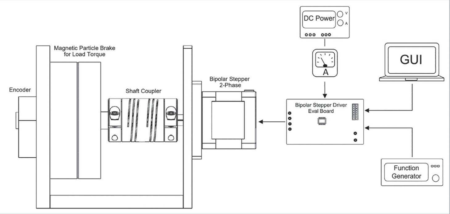
• A 24V dc bench supply placed in series with a current meter measures the dc current draw of the stepper motor under di erent load conditions. In addition, the 24V dc bench supply powers the stepper motor driver.
• The motor driver’s MotionLAB, which is compatible with the serial peripheral interface (SPI), configures the stepper motor driver’s parameters, such as the step mode, rated current, and additional motor settings.
• A function generator sends square pulses to the driver, which drives the motor forward.
Brushless dc motor test
Similar to the stepper motor test, the brushless dc motor test set-up includes a magnetic particle brake for load simulation, as well as a NEMA 17 BLDC motor with an integrated controller.
To power the controller, a 24V dc bench supply is used in series with a current meter to measure the dc current draw of the brushless dc motor under di erent load conditions. Then the MotionLAB GUI can drive the BLDC in speed control mode for this test.
Current draw comparison
Steppers typically operate under constant current, otherwise known as constant torque. This forces steppers to always draw the maximum current, regardless of the load on the motor shaft. As a result, steppers can provide maximum torque across the low-speed range. However, this also leads to large amounts of wasted energy in the windings in the form of heat.
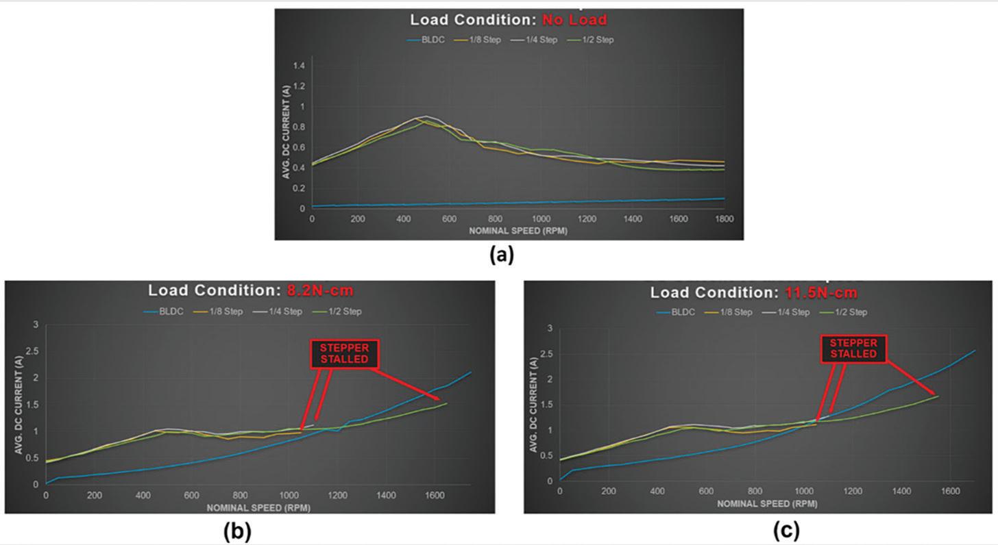
In this experiment, the stepper motor was tested in three microstepping resolutions: half-step, fourth-step, and eighth-step. The dc
The dc current draw at various motor speeds under di erent load conditions are current draw was recorded at various motors speeds under three di erent load conditions (no load, 8.2 N-cm, and 11.5 N-cm). The experimental results demonstrate the stepper motor’s less e cient measured dc current draw compared to a BLDC motor.


The no-load current draw was also measured for the brushless dc motor, half-step stepper motor, fourth-step stepper motor, and eighth-step stepper motor. The stepper motor draws a significantly higher zero-speed current than the BLDC, even when there is no mechanical operation. Furthermore, the stepper motor current draw remains high across the low-speed range. As the motor speed increases to the high-speed range, the stepper motor’s current draw begins to decrease due to the inductance of the motor windings and back EMF.

Next, the current draw was measured for the BLDC motor, half-step stepper motor, fourth-step stepper motor, and eighth-step stepper motor when there was some load added on the shaft. The stepper motors stall at high speeds because they have less current in the windings. Although microstepping increases the motor’s positional resolution, it also decreases the output torque. The eight-step and fourth-step stepper motors stalled at the midrange speed as well. Meanwhile, the BLDC motor only draws what it needs depending on the shaft’s load.
Under no-load conditions, the BLDC draws a small current to rotate the rotor. At the same time, the current draw increases if load is added to the shaft, allowing the BLDC motor to continue spinning at a higher speed than the stepper motor. Therefore, BLDC motors are more power-e cient compared to stepper motors due to their ability to draw current based on the load.

Power density comparison

Power density is a measure of motor output power per unit volume. Brushless dc motors typically have higher power density compared to stepper motors.
Using these dimensions, the volume can be estimated as 73 cm3 for the BLDC motor and 131 cm3 for the stepper motor. A motor’s output power is equal to the output speed multiplied by the output torque. The BLDC motor continues to spin at a higher speed compared to the stepper motor under the same load conditions, which means that the BLDC motor provides a higher power density, because it has a higher power output with a smaller volume.


