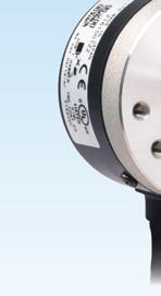
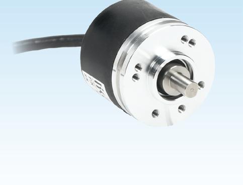
Light-duty encoders are cost-effective for applications with light shaft loads, perfect for industrial environments with good mounting conditions and flexible shaft couplings.
• Small bodies: 38mm or 40mm diameter
• 6mm solid, or 8mm hollow shaft
• Resolutions from 100 to 4096 ppr
• Universal output (works with HTL/open collector and TTL/line driver)
• Up to 200 kHz response frequency
• IP40, IP50, or IP65 environmental rating
• 2m cable with tinned leads
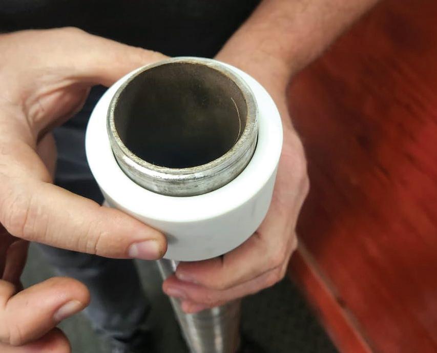
Measuring Wheel Systems
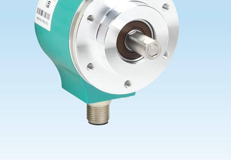
Starting at $299.00 (AR01-0250-HM12-A)
Starting at $154.00 (TRDA-20R1N100RZD)
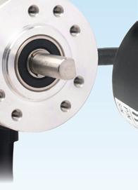
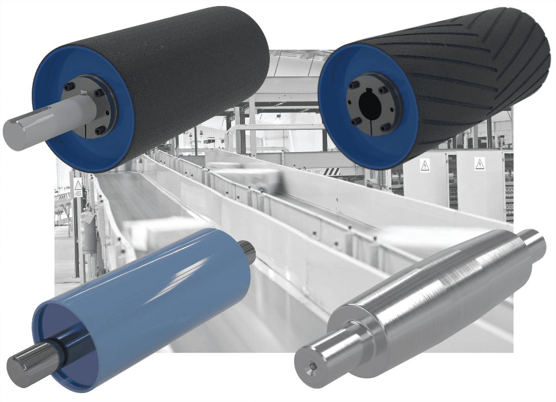
Our most popular style for industrial installations, these encoders are perfect for applications with moderate shaft loading and flexible shaft couplings.
• 2” or 50mm body diameter
• 2.5” removable flange on select models
• 1/4”, 3/8”, or 8mm solid shaft; 3/8”, 8mm, 15mm, or 30mm hollow shaft
• Resolutions from 1 to 16,384 ppr
• Universal output (works with HTL/open collector and TTL/line driver)
• Up to 500kHz response frequency
• IP50, IP64, or IP65 environmental rating
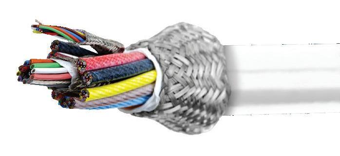
• 2m cable or MS (Military Style) or M23 connectors (mating connectors and pre-made cables sold separately)
• Metric and US/imperial wheel sizes
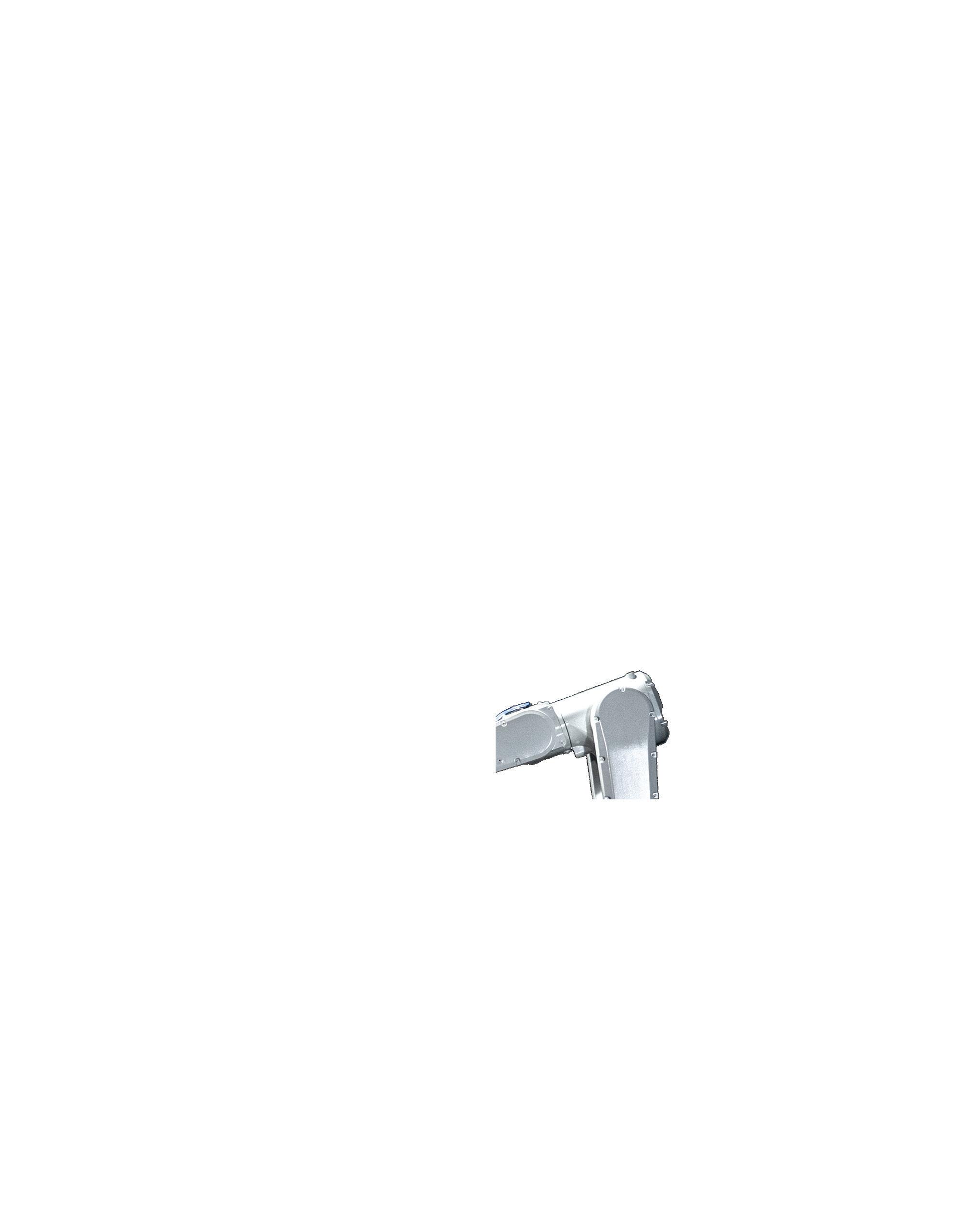
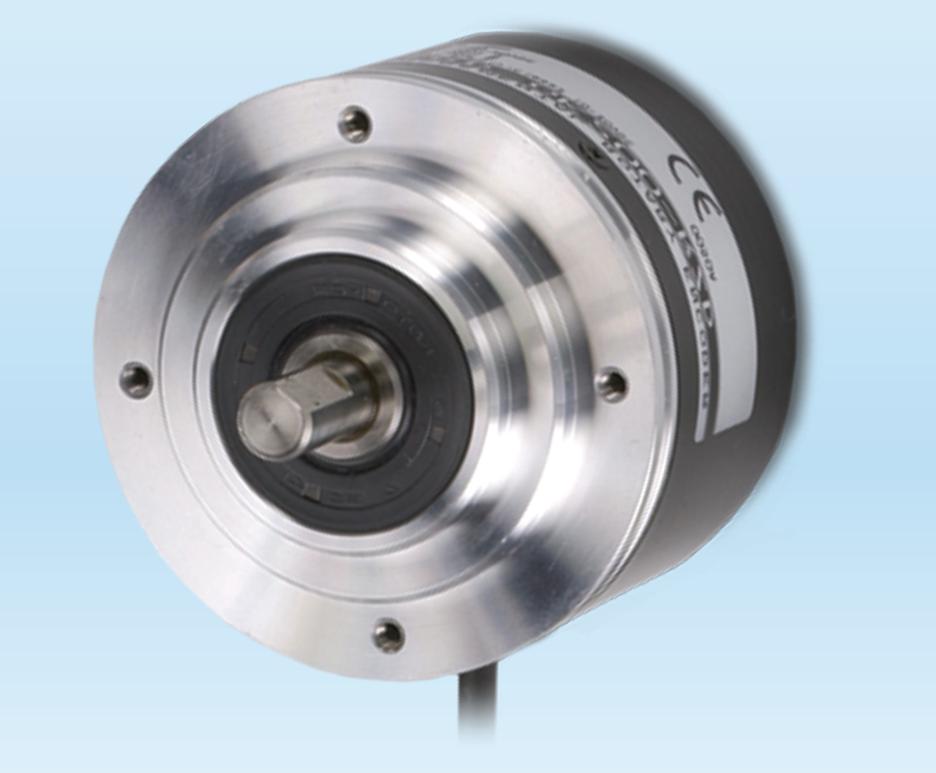
Heavy Duty Incremental
Starting at $319.00 (TRD-GK100-RZD)
For demanding applications, we offer the most rugged encoders available. Top-of-the-line bearings ensure a service life of 12 billion revolutions and allow significant shaft loading.
• 78mm body diameter
• 10mm solid shaft
• Resolutions from 30 to 5000 ppr
• Totem pole output (10-30 VDC, sink/source)
• 100 kHz response frequency
• IP65 environmental rating
• 2m cable with tinned leads
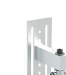
Medium-duty measuring wheels ride directly on the product (above or below) or a conveyor to measure or provide speed control feedback. These can also be used for cut-to-length and positioning applications.
• Optional 80mm wheel (250mm circumference)
• Spring loaded arm with up to 30mm deflection
• IP65 environmental rating
• Standard 4” wheel (12.5” circumference)
Learn more about the fundamentals of industrial encoder sensing technologies, motion detection theory, & signal output styles
www.go2ADC.com/wpe
WHITE PAPER
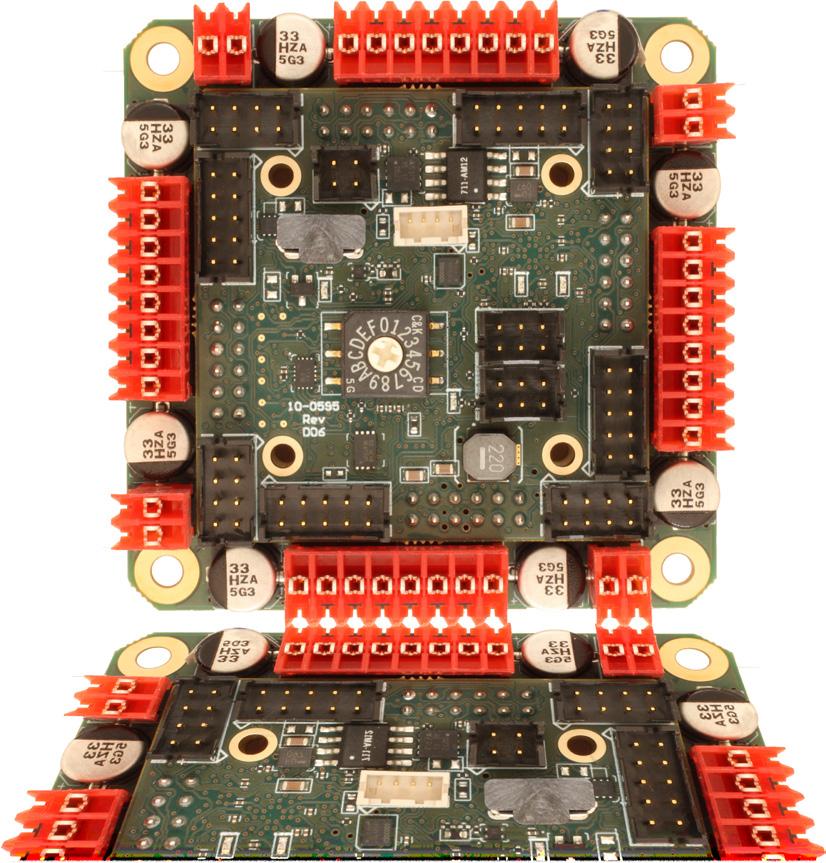
4 AXIS SERVO
- brushed or bldc motors
- 5 amps per axis - 16 analog inputs - 16 on/off drivers - home and limit in - live tech support - made in the USA
The Semiconductor Industry Association (SIA) predicts that 114,800 new jobs will be created in the U.S. semiconductor industry by 2030. However, it expects more than half of those jobs to go unfilled. Of the 67,000 vacancies, nearly 27,300 are pegged for engineers at the bachelor’s, master’s, and Ph.D. levels — and that’s just for one (extremely critical) industry. Across the U.S. economy, SIA predicts 273,000 engineers will be missing. It seems engineers aren’t earning degrees fast enough to meet demand. Plus, each year, thousands of international students get their degrees and get out of Dodge to work in other countries.
As part of the CHIPS Act, the Department of Energy (DOE) is on the hook for helping develop a skilled workforce to support semiconductor manufacturing. DOE aims to increase STEM professionals and provide more opportunities for minorities and community college graduates. It’s also supposed to leverage “programs that facilitate collaboration between and among teachers at elementary schools and secondary schools served by local educational agencies,” according to Section 10111.
Now, I live in a state where local school districts can’t pass levies to keep their buildings open and teachers employed, and the state legislature is trying to dramatically slash funding for public schools. In my state, taxpayers aren’t happy with how the other DOE manages their money, and parents and teachers are worried about their children’s education and future. Mind you, my state is also the new home for cutting-edge fabs that cost billions of dollars to build and are poised to strengthen the U.S. semiconductor supply chain.
How are we to develop a skilled technical workforce, from kindergarten through college, when we can’t even agree on bankrolling our schools? What underfunded community could possibly pump out enough engineers to fill the gaps?
2030 is a mere five years away. That’s not much time, yet a lot can change, and already is with the new administration. (It’s also 15 years after Doc and Marty tried to fix the future to prevent Marty’s son from screwing up his life while severely screwing up the space-time continuum in the process. I don’t recommend we take that route, and if you don’t understand the reference, I suggest you stream “Back to the Future” and its sequel immediately.)
I’m quite perplexed. SIA proposes fantastic recommendations to help close the workforce gap and get more folks into engineering degree programs and jobs. The CHIPS Act touts lovely prose on how government, academia, and industry can perform triple axles during the economy’s fluctuations and gracefully land on their feet, strides ahead of the rest of the world.
So, why is my son’s school closing? Why is my state denying millions of dollars to public education while multi-billiondollar fabs are being constructed? There seems to be a disconnect here. Perhaps the most hopeful option is to dust off the old flux capacitor, go back to 2015, and just buy shares of Nvidia when it was dirt cheap. That should fund an engineering education quite well. DW
Rachael Pasini
rpasini@wtwhmedia.com
linkedin.com/in/rachaelpasini
SOURCES:
• Chipping Away: Assessing and Addressing the Labor Market Gap Facing the U.S. Semiconductor Industry: wtwh.me/chippingaway
• 2024 State of the U.S. Semiconductor Industry: wtwh.me/2024semiconductor
Innovation in PLCs has brought to the fore new functions and capabilities to answer industry needs and address new application challenges.
Leadscrews are often used in NEMA-stepmotor linear actuators. Improvements in the manufacture of these leadscrews have led to their increased adoption.
Automated disassembly and recovery addresses environmental and regulatory demands as well as worker welfare.
These companies represent the
EDITORIAL
VP, Editorial Director Paul J. Heney pheney@wtwhmedia.com
Digital Production Specialist Elise Ondak eondak@wtwhmedia.com
WEB DEVELOPMENT
Web Development Manager B. David Miyares dmiyares@wtwhmedia.com
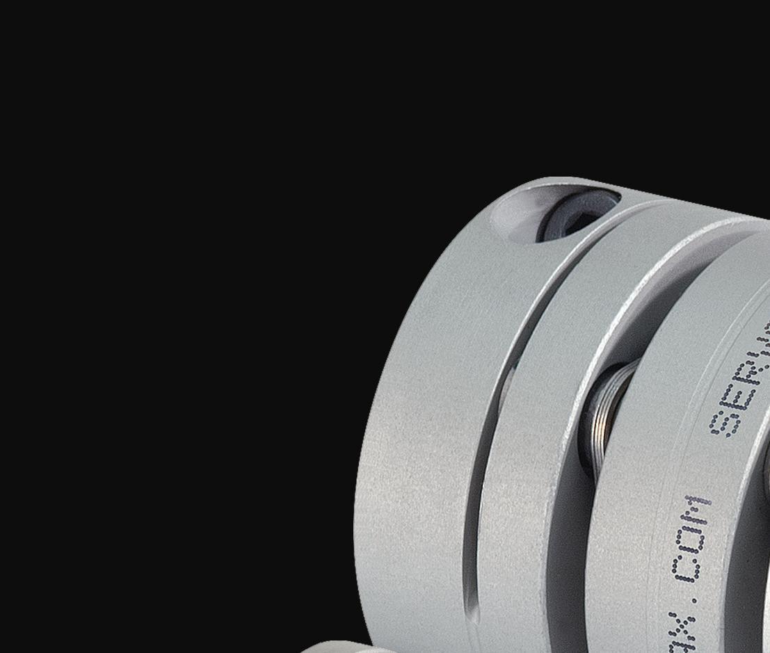
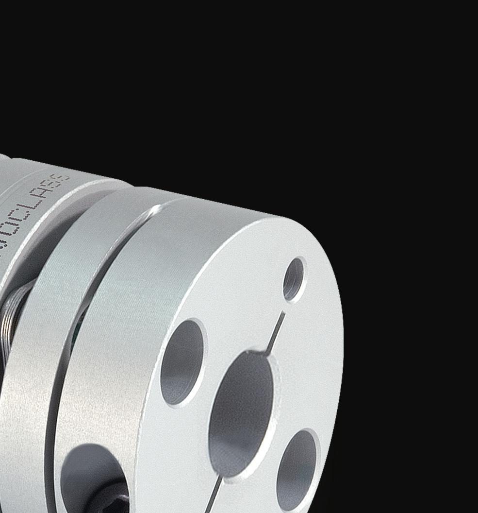
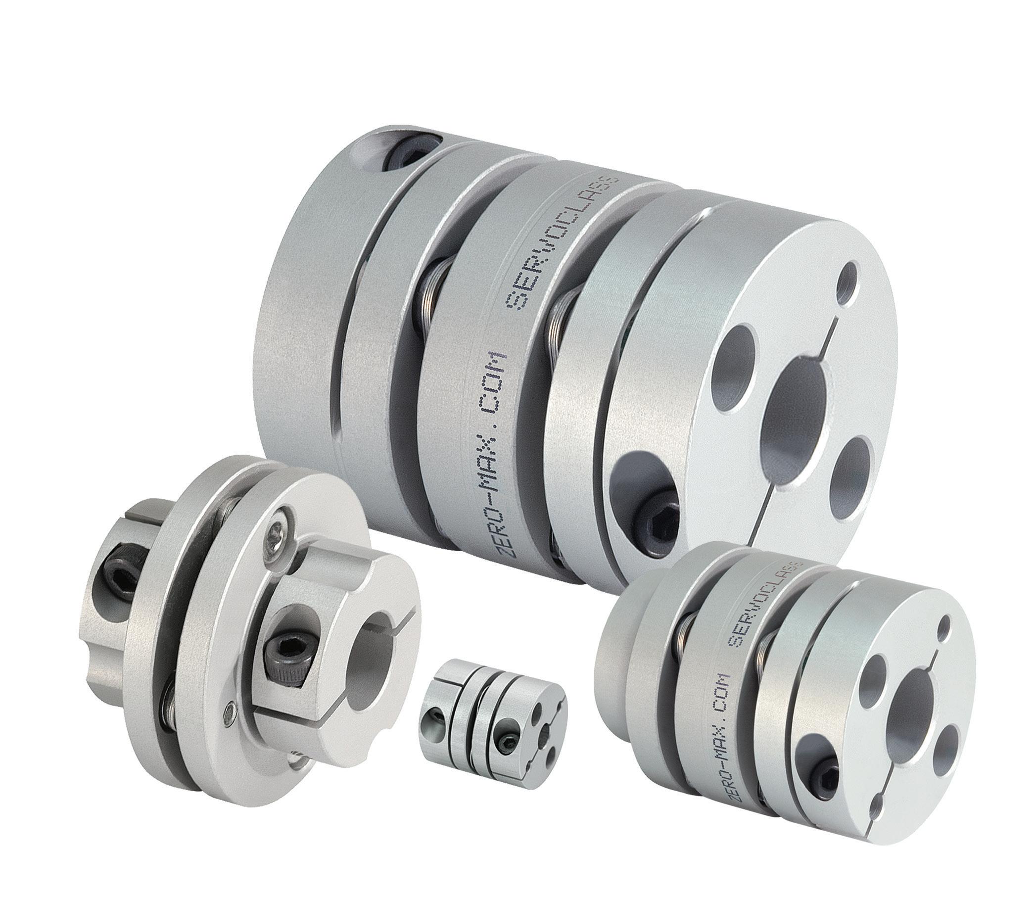
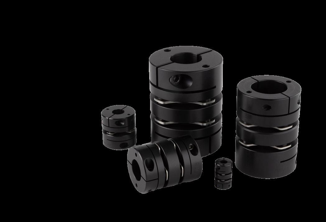
LARGE BORE DISC COUPLINGS
• Bore sizes up to 1-3/4” and 45mm
• Torque up to 1150 in-lbs (130 Nm)
• Reduced vibration due to a balanced design
• Double disc for increased misalignment
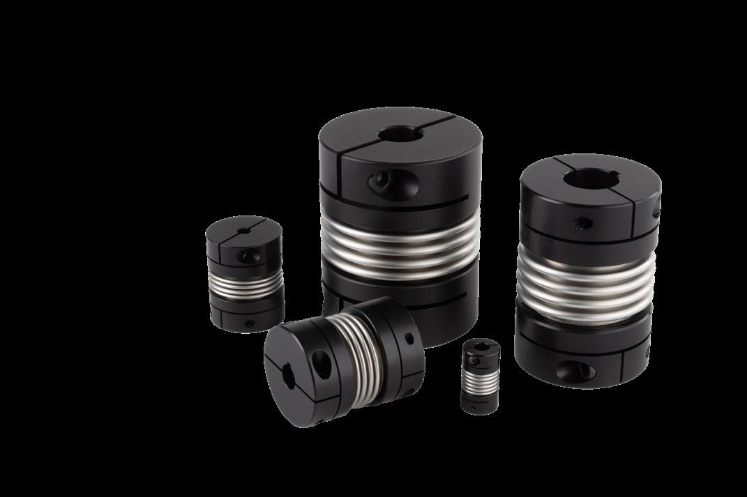
LARGE BORE BELLOWS COUPLINGS
• Bore sizes up to 1-3/4” and 45mm
• Torque up to 1300 in-lbs (152 Nm)
• Reduced vibration due to a balanced design
• Highest torsional stiffness
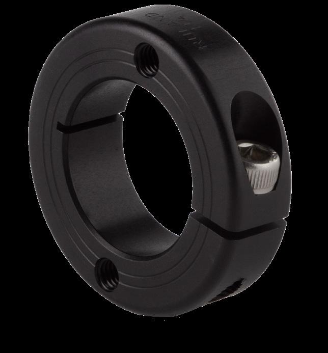
SHAFT COLLARS WITH FACE HOLES
• Maximum mounting flexibility with drilled holes
• Most secure mounting connection with thread- ed holes
• Bore sizes from 3/8”-2” and 10-50mm
• Carefully made by Ruland in aluminum, steel, and stainless steel
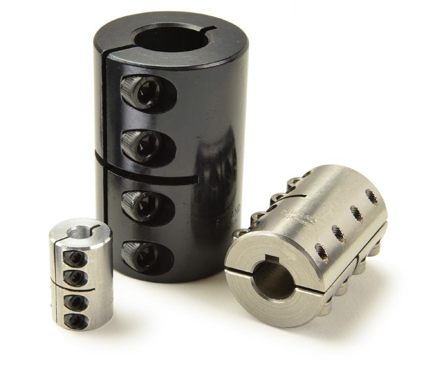
INCH-METRIC RIGID COUPLINGS
• Widest selection of standard inch-tometric bores with or without keyways
• Supplied with proprietary Nypatch® anti-vibration hardware
• One-piece style for easy installation
• Two-piece style with a balanced design
Join us at the 2025 AMUG Conference March 30 - April 3, 2025 | Chicago, IL, USA
Expertise
Gain practical knowledge through proactive participation and handson experience
n Become more productive through AMUG’s community of problem solvers
n Learn and share expertise, best practices, challenges, and application developments
Network
Impactful networking without any agendas
n Embrace the camaraderie and enjoy effortless networking
n Form meaningful connections through casual conversations
Value
Get the most value of any conference with an ALL-INCLUSIVE program
n 4-day conference
n Hands-on workshops
n Technical competition
n AMUGexpo
n Meals and entertainment throughout
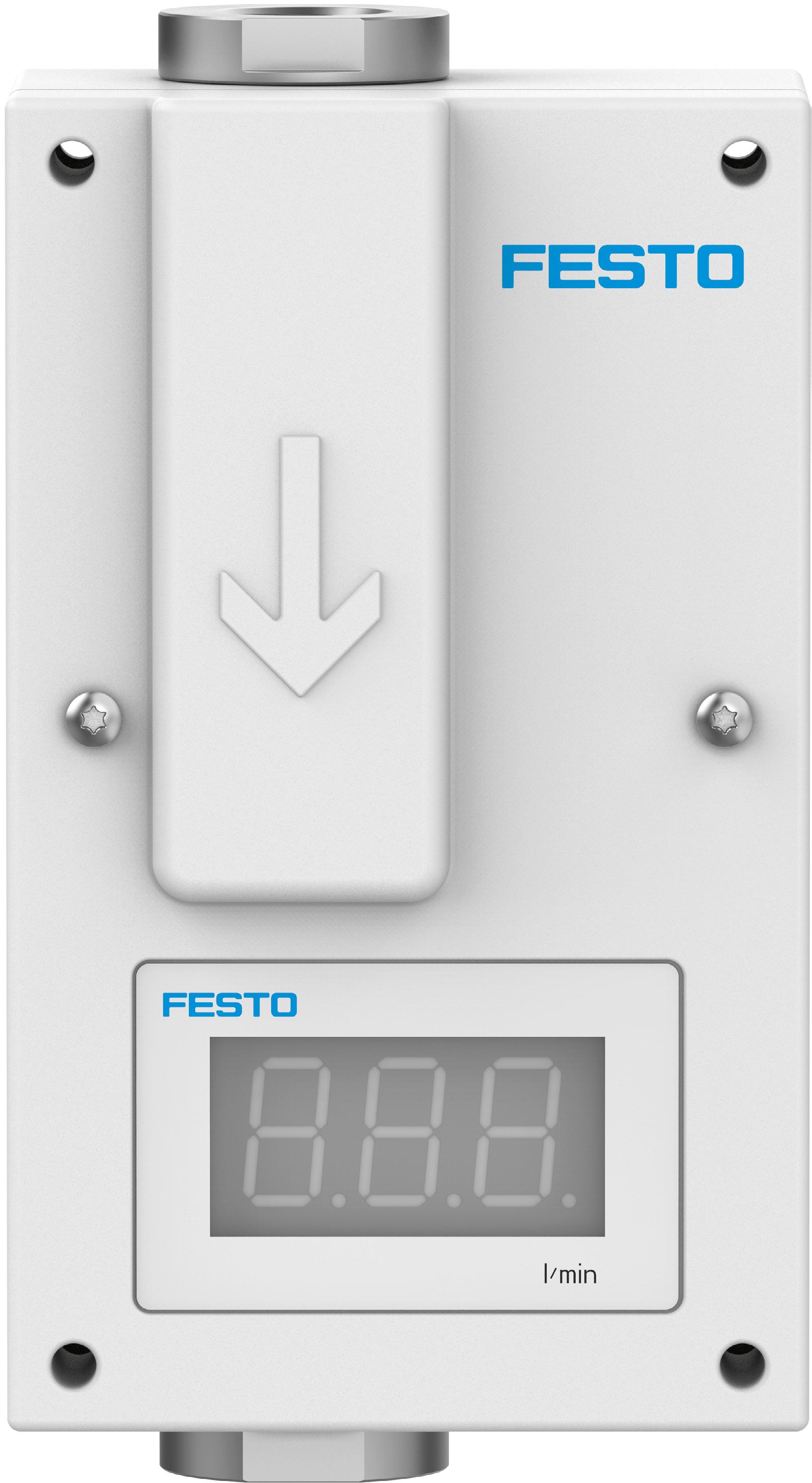
New nitrogen purging technology can save millions
Semiconductor fabrication plants (fabs) use front-opening unified pods (FOUPs) to securely transport wafers from one manufacturing step to the next in an oxygen- and particle-free environment. During a research effort, Festo found that its new generation of low-energy flow-control valves used in FOUP purge systems can reduce nitrogen gas (N2) consumption by up to 75%.
The company estimates that for every 1,000 FOUPs using precision N2 flow-control systems, fabs can save $163,000 annually in air-separation unit (ASU) electricity costs through reduced N2 demand. This figure is based on a $0.06 per kWh utility rate. Considering that the largest fabs manufacturing 300 mm wafers can have upwards of 20,000 FOUPs active in daily production and that fab electricity rates can go higher than $0.06 per kWh, the $163,000 can quickly multiply into millions of savings.
For every 1,000 FOUPs equipped with new generation purge systems, Festo calculates a reduction in the environment of 1,045 metric tons of carbon dioxide (CO2) emissions directly from electricity generation. Putting this reduction into perspective, 1,045 tons of CO2 emitted into the atmosphere is the equivalent of burning 1.2 million pounds of coal, according to the U.S. Environmental Protection Agency’s greenhouse gas equivalencies calculator.
Festo’s piezo-based controlled-flow system reduces N2 flow from 20 nl/min to 5 nl/min per FOUP. The N2 purge system also significantly lowers the risk of oxidation and particle contamination. It has a peak particle size per switching cycle of 0.1 μm, about five times smaller than current FOUP N2 purge systems. Closed-loop control ensures an accurate, reliable, stable, and linear flow rate without hysteresis. The system’s repetition accuracy is rated at ±0.25% of the setpoint.
Low-friction piezo technology is designed to prolong controller service life and minimize maintenance. The solution requires less than 1 W and reduces energy consumption by about 80%. The N2 purge flow controllers consist of a two-way proportional valve, integrated flow sensor, and integrated electronics that include a power supply, high-voltage technology for the piezo bender, piezo proportional control valve, and a stable, precise control loop for the sensor. DW
Festo • festo.com
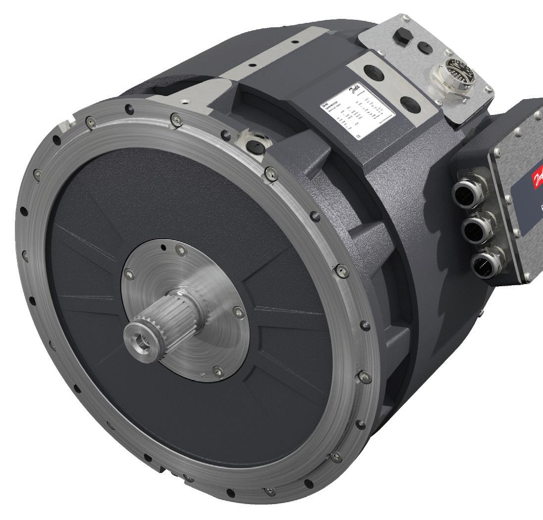
Chao Wang, head of portfolio management for Danfoss Power Solutions’ Editron division, stated that there are few options for true 690-V mobile-grade inverters and motors in the market. He said most are based on industrial solutions with lower vibration and shock tolerance.
To fill that gap, Danfoss developed the Editron EMPMI375, based on synchronous reluctance-assisted permanent magnet technology, to function as a motor and a generator. It is designed to work with the Editron ECC1700B inverter, offering a system solution for 690-Vac and 1,050-Vdc applications, such as winches, cranes, marine vessels, and mining and material handling machinery.
This model is the same size and shape as the EMPMI375 500-V motor and includes the same standardized options. It is small and lightweight, up to 96% efficient throughout its operating range, and has a compact aluminum frame structure with an IP67 ingress protection rating.
The new EM-PMI375 690-V motor and EC-C1700B inverter are the first two pieces of Danfoss’ 690-V ecosystem, and engineers can expect more to come. The 690-V motor’s housing design enables a maximum operational altitude of 3,000 m, and the 500-V motor’s nominal altitude rating increased from 1,000 to 4,000 m.
The EM-PMI375 electric motor is available in four sizes (T200, T500, T800, and T1100) to suit a range of torque and power needs. All models have a speed range of up to 4,000 rpm. The motors are liquid-cooled with low coolant flow requirements. DW
POWER TRANSMISSION RETAINING DEVICES & maintenance & assembly
WHITTET-HIGGINS manufactures quality oriented, stocks abundantly and delivers quickly the best quality and largest array of adjustable, heavy thrust bearing, and torque load carrying retaining devices for bearing, power transmission and other industrial assemblies; and specialized tools for their careful assembly.
Visit our website–whittet-higgins.com–to peruse the many possibilities to improve your assemblies. Much technical detail delineated as well as 2D and 3D CAD models for engineering assistance. Call your local or a good distributor.
• MACHINE TOOL
Combining precision and simplicity with closed-loop control
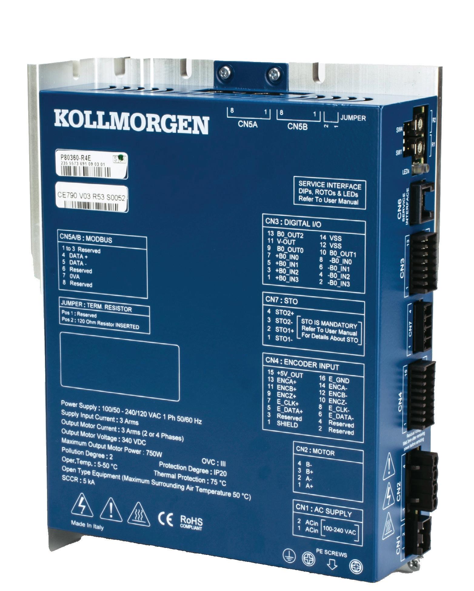
Stepper systems are usually open-loop and do not require position feedback. However, machine builders can use an encoder to monitor the motor’s position and speed to enhance performance. The encoder sends feedback to the stepper drive that adjusts the motor’s current and position for greater precision and to reduce errors.
For example, Kollmorgen’s P80360 stepper drive, part of the P8000 series, includes closed-loop position control and full programmability. It combines the precision of servo systems with the reliability and simplicity of stepper technology. Its stepless control provides smooth, quiet operation and consistent performance across a broad speed range. The closed-loop position control incorporates encoder feedback to automatically correct overshoot or undershoot errors, enhancing precision and reducing scrap or equipment damage risks. This also improves energy efficiency by optimizing motor operation and reducing heat generation.
The drive is fully programmable through Kollmorgen Space software, enabling point-to-point movements and complex motion sequences without requiring an external PLC or indexer. It also includes a Motor Wizard tool for quick machine setup with Kollmorgen motors, requiring only basic input parameters, such as velocity and acceleration.
The stepper drive supports stepper motors with phase currents up to 3.0 A rms (4.2 A pk). It is suitable for various applications, including labeling systems, indexing tables, CNC machines, XYZ gantry systems (such as 3D printers), packaging machines, and medical laboratory equipment. The P8000 series, including the P80360, is certified for CE, RoHS, and REACH standards and provides precision for motors powered by 100 to 240 Vac single-phase power. DW
Kollmorgen • kollmorgen.com
MADE IN INCH, METRIC and O-RING SIZES
• Round, Flat and Connectable Polyurethane Belts
• Very Clean Operation Lifetime Warranty Against Manufacturing Defects
• Eliminates Tensioning Devices
• Exceptional Abrasion Resistance
Reduce energy waste with real-time monitoring
Most manufacturers, including original equipment and industrial manufacturers, consumer packaged goods companies, and food and beverage producers, face mounting pressure to increase productivity while reducing energy use and environmental impact. Yet industrial machinery is energy-intensive, consuming high power even when idle. To meet efficiency and sustainability goals better, operators need better visibility into their facilities’ energy use to address waste and inefficiencies.
To help simplify industrial electricity monitoring, Emerson launched a preengineered hardware and software solution called Energy Manager. This solution is ready out of the box and monitors asset energy use in real time. Manufacturers can gain insight into energy consumption, operating costs, and CO2 emissions to maximize energy and operational efficiency. They can quickly view detailed values for savings opportunities, such as idle consumption and peak loads. The software’s dashboard provides
asset-specific energy use, associated costs, and CO2 emissions for up to 10 endpoints (expandable to 50 endpoints with a license).
This level of visibility gives organizations greater control to identify idle machines and optimize machine schedules during off-peak hours. This, in turn, can reduce electricity use across the plant floor and significantly lower overall utility costs. Most facilities can reduce energy waste by up to 10 to 30% and carbon emissions by up to 15 to 30%.
The solution is scalable and can integrate with new or existing energy meters. The software is preinstalled on edge hardware, such as the PACSystemsTM RXi2-BP industrial PC, or manufacturers can use a stand-alone application installed in a virtualized environment. For more extensive media and utilities monitoring, the Energy Manager can be paired with the Emerson Compressed Air Manager for a streamlined view of energy costs and compressed air usage of machines across a production line, factory, and site.
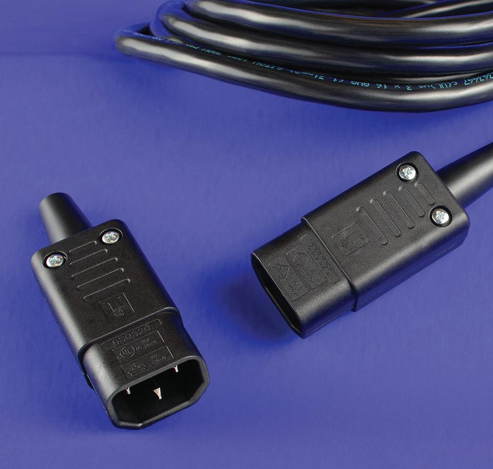
Interpower North American and international cords and cord sets provide the correct AC power to allow country-specific customers to safely connect to their mains power without reconfiguration. Interpower manufactures stateof-the-art electrical cord sets for global markets with 1-week U.S. lead times.
Interpower cords and components are manufactured in accordance with Interpower’s product quality plan: hipot testing, continuity testing, and ground testing with inspections after each stage of the manufacturing process.
Emerson emerson.com
• EDITED BY MIKE SANTORA
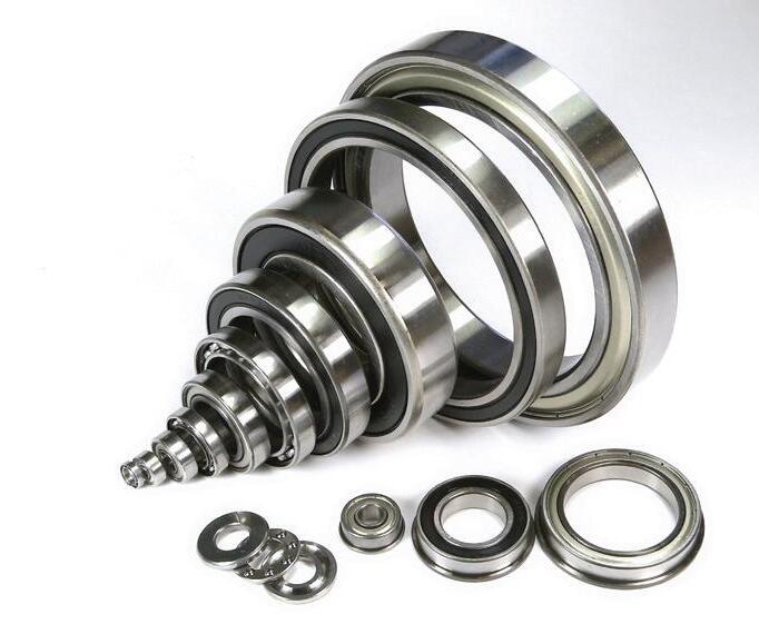
Order up! Bearings help with autonomous robotic kitchen assistants
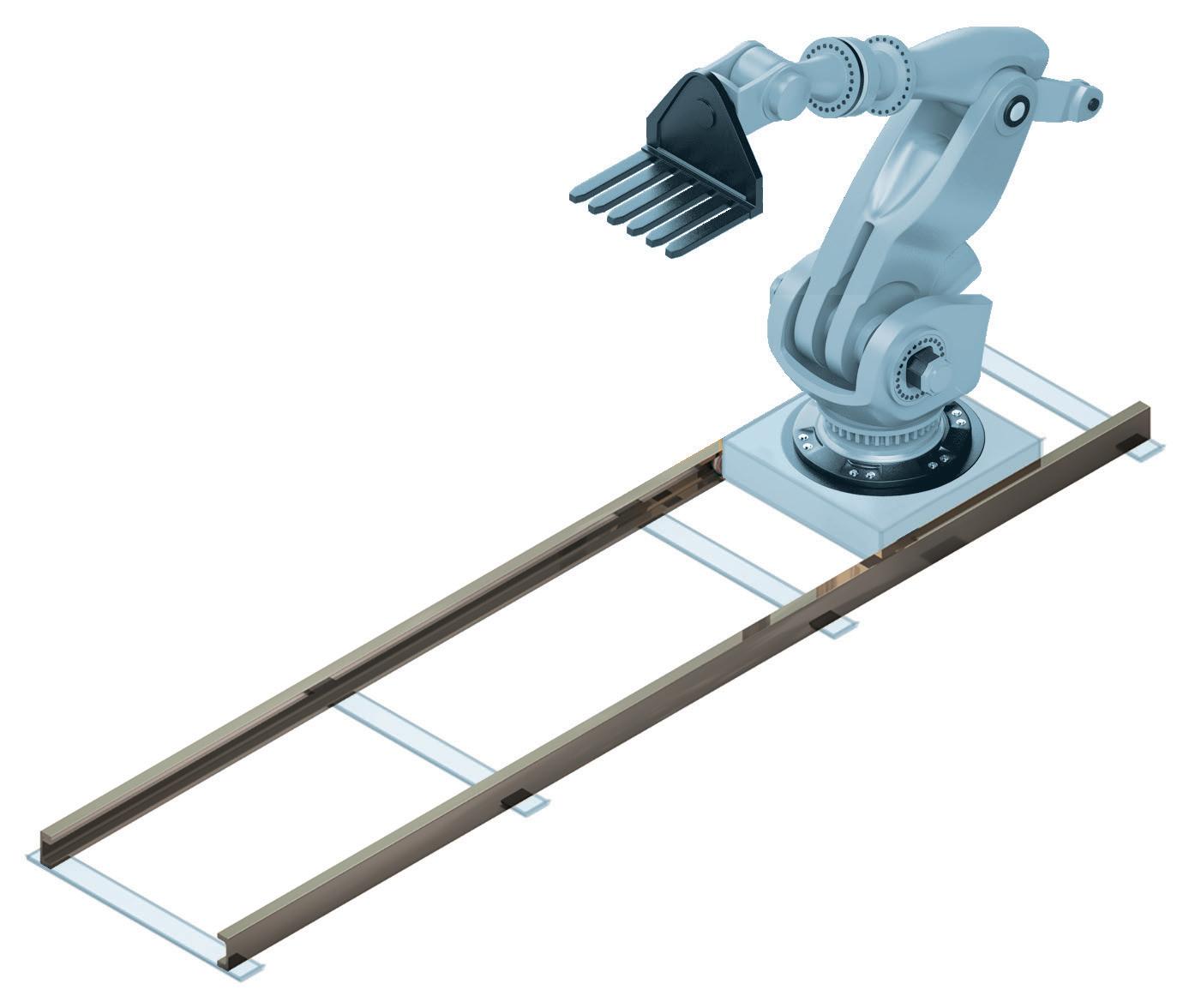
Cobots, unlike traditional industrial robots, are designed to work near humans. Achieving this necessitates levels of precision, safety, and reliability in cobots that are far higher than their industrial counterparts. Flippy, for instance, operates safely alongside human workers, showcasing the high standards required for such collaboration.
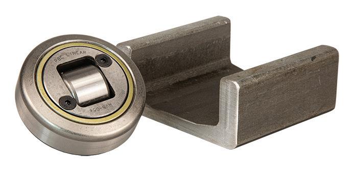
Bearings play a pivotal role in achieving these standards. Precision bearings in particular, are essential for the smooth and accurate movement of cobots, allowing them to perform delicate tasks with the precision of a human hand.
The economic impact of cobots extends beyond individual businesses to the broader economy. By enabling
The vision of robots and humans working side by side is now a reality driven by the rise of collaborative robots — or cobots. Flippy, the world’s first autonomous robotic kitchen assistant, is one example. Debuting in 2017, Flippy flips burgers, fries, sides, and more. But what makes these cobots so effective? One crucial factor is industrial bearings. Here, Chris Johnson, managing director at bearing specialist SMB Bearings, explores how precision bearings are enhancing the performance and reliability of cobots.
Bearings also contribute to the fail-safe mechanisms in cobots. In the event of a malfunction, the robot can come to a controlled stop which helps avoid injury to human coworkers without the need for extensive safety barriers.
companies to automate more processes and increase productivity, cobots can contribute to economic growth and competitiveness. For example, a report by McKinsey & Company estimates that automation technologies could help raise global productivity growth by 0.8 to 1.4% annually.
The prospects for cobots
According to Fortune Business Insights, the market for cobots is expected to grow at a compound annual growth rate (CAGR) of 42.7% from 2020 to 2028. This growth is driven by several factors including the increasing need for automation and the push for improved workplace safety. Cobots are not replacing human labor but are instead augmenting it by performing repetitive
and dangerous tasks, while allowing humans to focus on more specialized tasks.
Manufacturers are particularly drawn to cobots for their flexibility and ease of integration. Unlike traditional robots, which often require extensive reprogramming and retooling, cobots can be quickly adapted to new tasks and environments. This makes them suitable for small and medium-sized enterprises (SMEs) that need to remain agile and responsive to market changes.
But why are industrial bearings so critical to the functionality of these machines? Bearings ensure these robots can move fluidly, reducing wear and tear and extending the life of the machinery.
In terms of efficiency, bearings reduce the friction between moving parts, which
decreases energy consumption and increases the operational speed of cobots. This is particularly important in industries like electronics manufacturing, where speed and precision are essential. The ability to maintain high speeds without compromising accuracy allows cobots to significantly boost manufacturers’ productivity.
Consider the automotive industry, where cobots are increasingly used for tasks like assembly, painting, and welding. These applications demand high degrees of precision and reliability as even minor errors can lead to significant defects.
Safety first
Safety is a primary concern when integrating cobots into a human workspace. The bearings used in cobots are designed to provide accuracy and repeatability, ensuring that the robots’ movements remain controlled and predictable. This predictability is crucial for preventing accidents and ensuring a safe working environment.
Bearings also contribute to the failsafe mechanisms in cobots. In the event of a malfunction, the robot can come to a controlled stop which helps avoid injury to human coworkers without the need for extensive safety barriers.
The food processing industry is another area where cobots are making significant inroads. Here, the precision and reliability of bearings are essential not only for the robots' performance but also for maintaining hygiene and safety standards. Bearings used in food processing cobots are often made from stainless steel or other materials that resist corrosion and can withstand frequent cleaning and sterilization.
Advanced materials and coatings
Advances in bearing technology are also driven by the development of new materials and coatings.
For instance, ceramic bearings are gaining popularity due to their superior performance characteristics, including higher resistance to wear and corrosion compared to traditional steel bearings. These properties, and the ability to run unlubricated, make ceramic bearings a possibility for use in cobots, especially in environments that involve high temperatures, exposure to chemicals or where weight reduction is required.
What’s more, specialized coatings such as Teflon and graphite can be applied to bearings to further reduce friction and improve their durability. These advances not only improve the performance and longevity of bearings but also contribute to the overall efficiency and reliability of cobots. By reducing the need for frequent maintenance and replacements, these advanced bearings help manufacturers achieve higher levels of productivity and cost-effectiveness.
As cobots continue to evolve, the future of cobots is bright. With precision bearings at their core, cobots like Flippy are paving the way for a new era of collaboration between humans and robots. These bearings ensure smooth, reliable operation, enabling cobots to perform tasks with high precision and safety. The right components, like advanced bearings, are key to unlocking limitless possibilities for cobots and the industries they serve. DW
SMB Bearings • smbbearings.com
Bearings play a pivotal role in achieving these standards. Precision bearings in particular are essential for the smooth and accurate movement of cobots, allowing them to perform delicate tasks with the precision of a human hand.
® With Interpower cords, cord sets and components, you don’t have to worry about waiting on North American and international cords and cord sets. With over 2 million cords and components currently in stock to ship the same day, and 1-week U.S. lead times on customized country-specific power cords, you can ease into the new year without stressing about your electrical design. Interpower cord sets provide the correct AC power for country-specific customers to safely connect to the mains power.
Toll-Free Phone: (800) 662-2290
E-mail: info@interpower.com
Business Hours: 7 a.m.–5 p.m. CST Order Online! www.interpower.com ®
• EDITED BY MIKE SANTORA
Polymer guide carriages knock it out of the park
The igus carriages operate without lubrication, eliminating the risk of debris embedding in the lubricants and affecting precision.
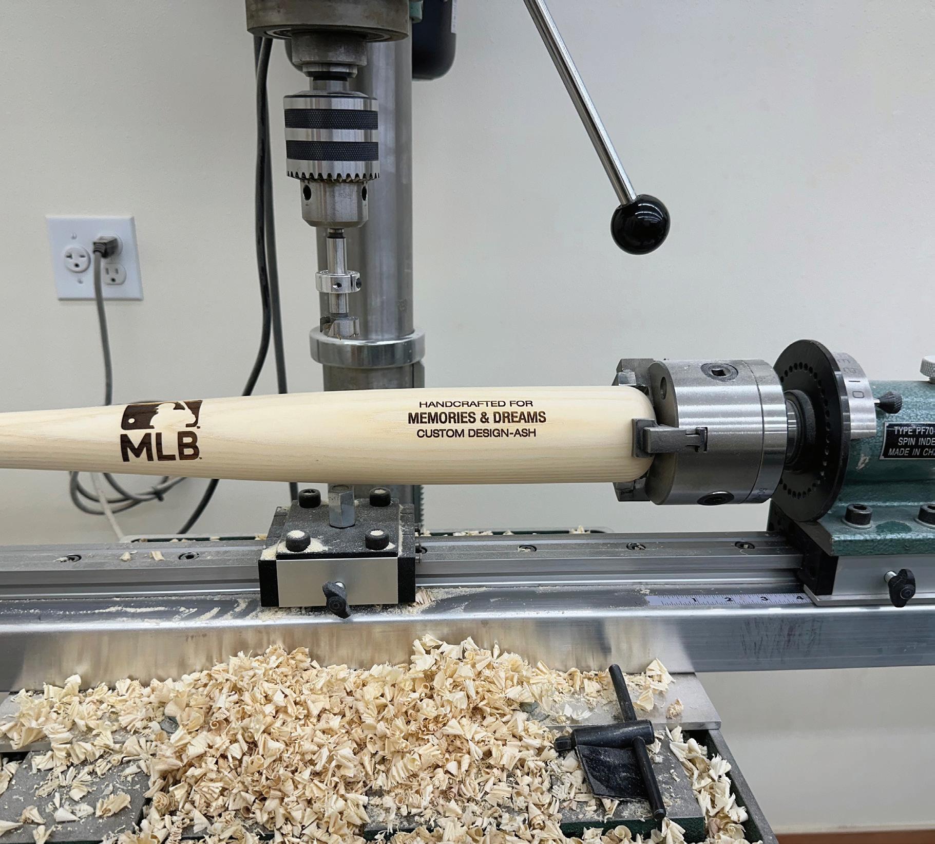
In 2013, the New York Yankees presented newly retired Hall of Fame pitcher and legendary closer, Mariano Rivera with a unique rocking chair made entirely from baseball bats. The Supple Rockers rocking chair created quite the buzz and a good laugh during the retirement ceremony. Whether for professional athletes or sports enthusiasts, these custom chairs are more than just pieces of furniture — they signify a one-of-a-kind experience for anyone with a passion for the game of baseball.
Based in Astoria, Oregon, Supple Rockers handcrafts each rocking chair from genuine baseball bats. Six bats and two wooden balls form each chair’s structural components. The backrests, which can be laser-engraved with names, dates, or unique ticket-stub
designs, are made from Northern white ash lumber, known for its strength, durability, and aesthetic appeal. The seats are upholstered with premium, topgrain cowhide leather — hand-sewn with baseball stitch details.
The creation of each Supple Rocker is a meticulous process that relies on engineering as much as it does art. That’s because each chair requires the utmost precision to achieve the balanced, final product. One of the mechanical components critical to each rocker’s success — and dubbed the “MVP” by Dan Supple, Owner and Principal Craftsman of Supple Rockers — is a linear guide carriage from igus.
Supple, a former single-A baseball player, founded Supple Rockers in 2009. Although building each chair is predominantly a hand-crafted process
In this story, we look at how igus linear guide carriages made from motion plastics have contributed to the success of one company’s baseballthemed rocking chairs.
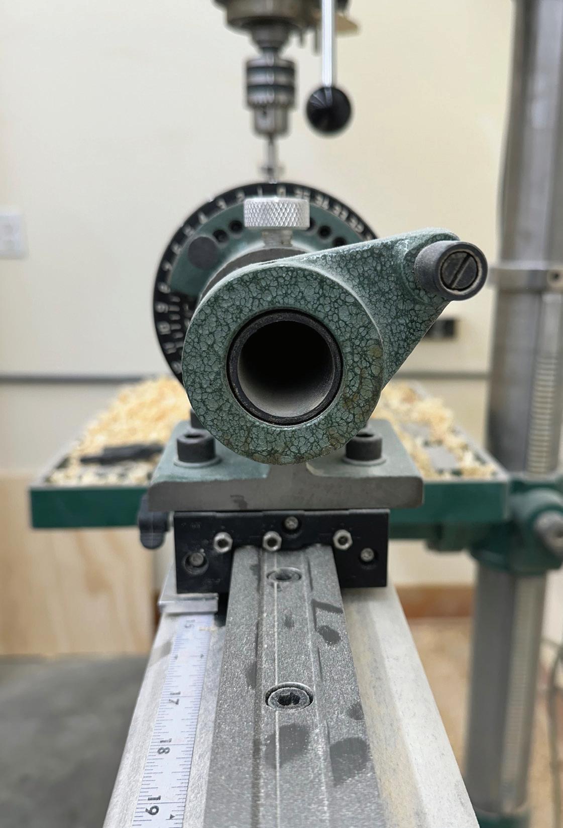
— one that takes roughly two weeks to complete — Supple is no stranger to automation. Already familiar with automated equipment and suppliers from his previous line of work in the canned salmon business, Supple contacted motion plastics company igus when he needed linear guide carriages for an indexing machine. This machine enables the craftsmen to slide and rotate the bats beneath a drill press machine.
“Building rocking chairs requires a lot of geometry to achieve the right balance,” Supple said. “The igus carriages keep each bat perpendicular to the drill press, ensuring the holes we’re drilling are perfectly aligned. It’s critical to move the bats precisely so we can space the holes evenly and get a consistent depth each time. If the holes aren’t precise, the entire chair will be thrown off balance.”
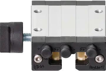
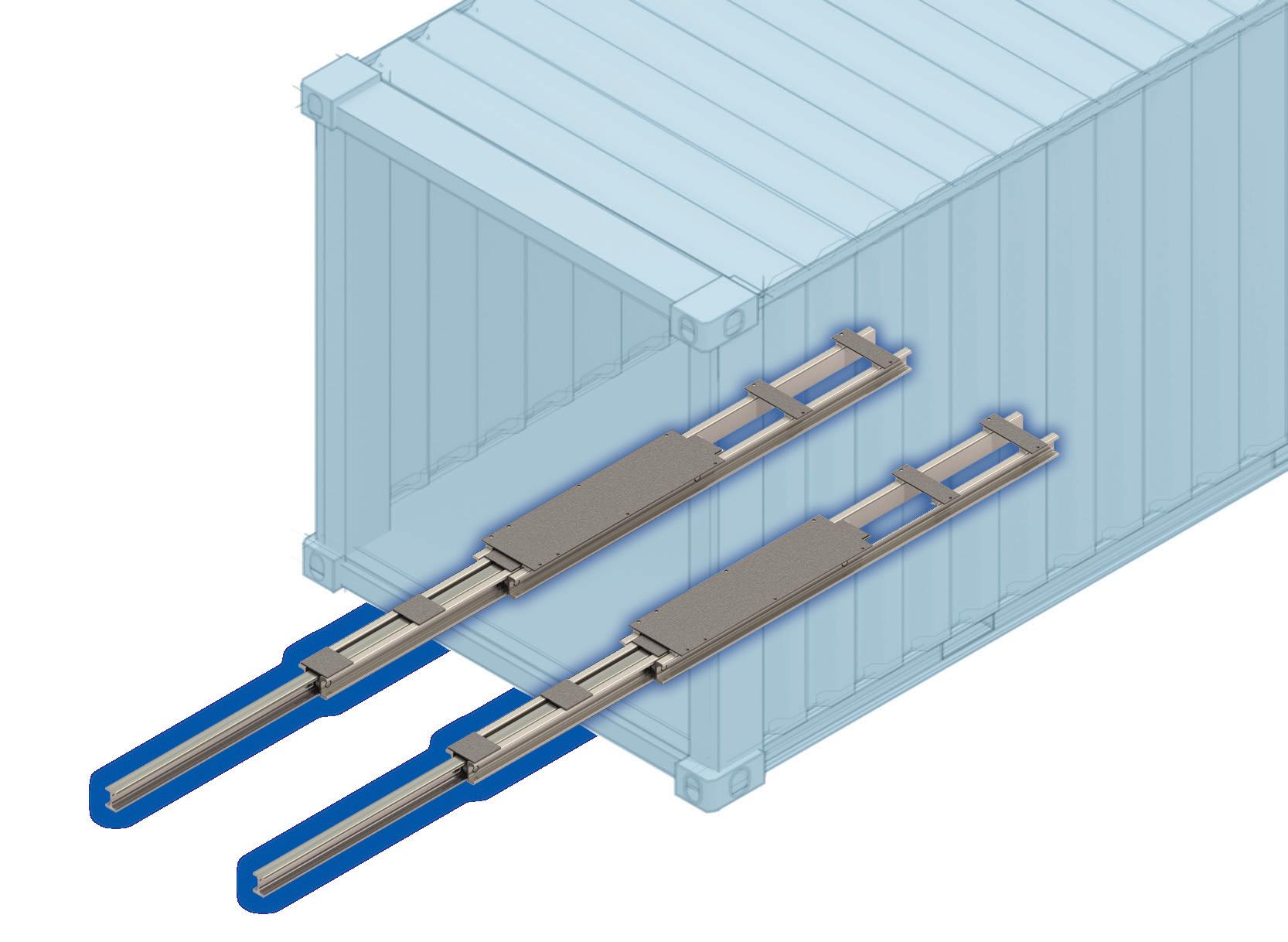
The igus drylin T series standard carriage, made from highperformance polymers.
The indexing machine’s 8-ft rail incorporates four igus drylin T series standard carriages.
The indexing machine’s 8-ft rail uses four igus drylin T series standard carriages, on top of which the craftsmen place and slide each bat during the drilling process. Each carriage includes a hand clamp and is constructed from aluminum and iglide J, a highperformance polymer that offers wear resistance and low friction. The T series is compatible with standard guide rails of 15, 20, 25, and 30 mm (widths) and are dimensionally interchangeable with recirculating ball bearing guides.
The drylin T carriages offer several characteristics that make them a suitable choice for the precision-driven Suppler Rocker crafting process. Their adjustable bearing clearance allows users to fine-tune the carriage alignment, ensuring optimal performance with minimal play. Carriages also operate without lubrication, eliminating the risk of debris embedding in the lubricants and affecting precision. The absence of rolling elements also reduces the risk of misalignment and wear that often occur in traditional bearings. Together, these features enhance the reliability and accuracy of the drylin T systems.
customizable,
In addition to their precision, drylin T carriages are maintenance-free, enabling craftsmen like Dan to “set them and forget them.” That’s because these polymer components don’t require grease or oil-based lubricants — unlike recirculating ball bearing systems, which drive more downtime and maintenance costs. In addition, iglide J’s material properties contribute to a longer service life, enabling the drylin carriages to resist wear and corrosion — even in the presence of wood shavings and other debris.
“In all the years I’ve used and operated the igus carriages, I’ve never had an issue with them,” Supple said. “Their performance is just top-notch.”
Since founding Supple Rockers, Supple has created 123 rocking chairs — each one of which is unique and tells its own story. “Yet at the same time, they’re pretty technical,” he said. “It’s taken us years of pounding our pencils on the drafting table to get them right. Without the igus carriages, we couldn’t do what we’re doing.” DW
igus • igus.com
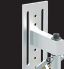
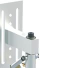
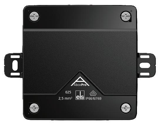
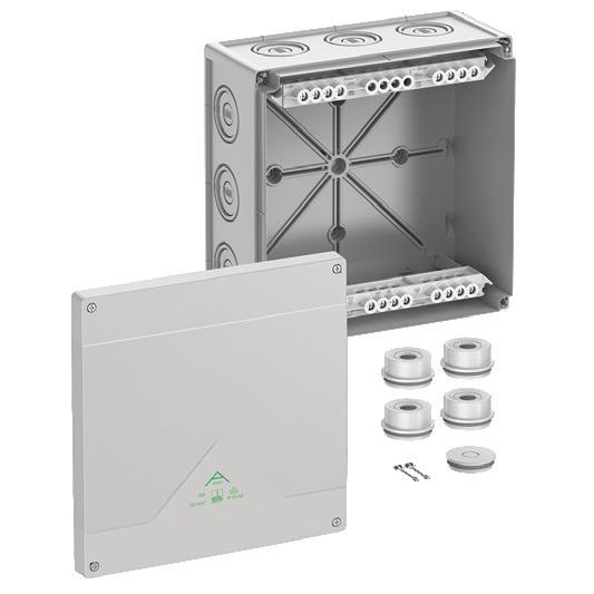
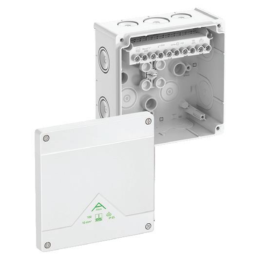
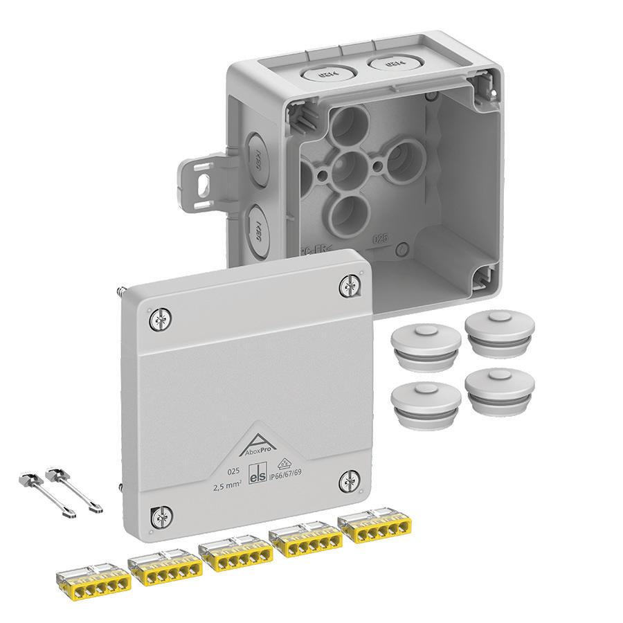
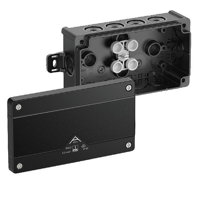
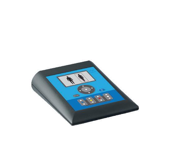
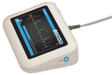
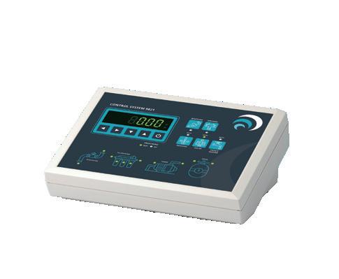
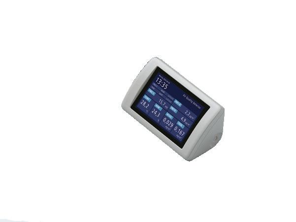
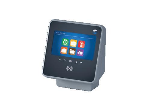
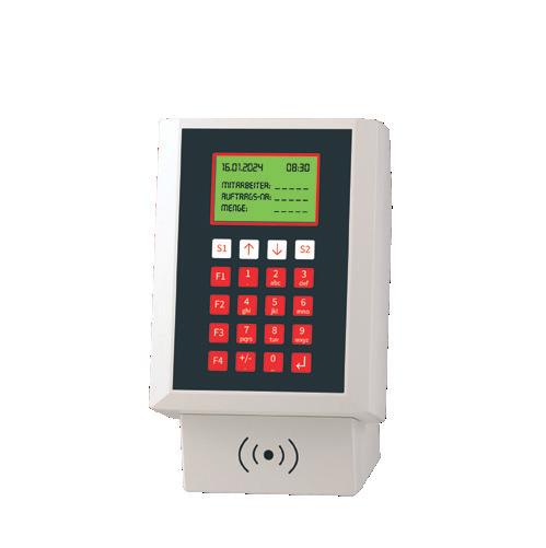
TERMINAL ENCLOSURES
Elevate your electronic terminals with our sleek sloping-front table-top/wall-mount enclosures. Designed for optimal ergonomics, these stylish housings enhance functionality and esthetics. Choose from a wide selection of models o ering recessed control panels, protection up to IP 65, battery compartments and customizing options to meet your specific needs.
Request a sample today!
Unique and
each Supple Rocker is made from Northern white ash lumber and features seats made from top-grain cowhide leather.
• EDITED BY MIKE SANTORA
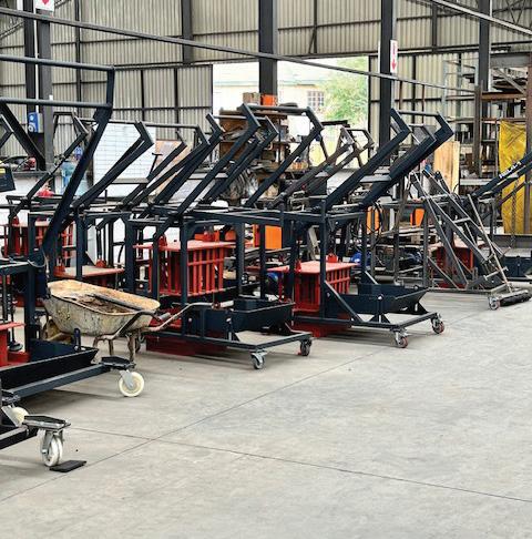
Brick machine supplier embraces the benefits of new bushings
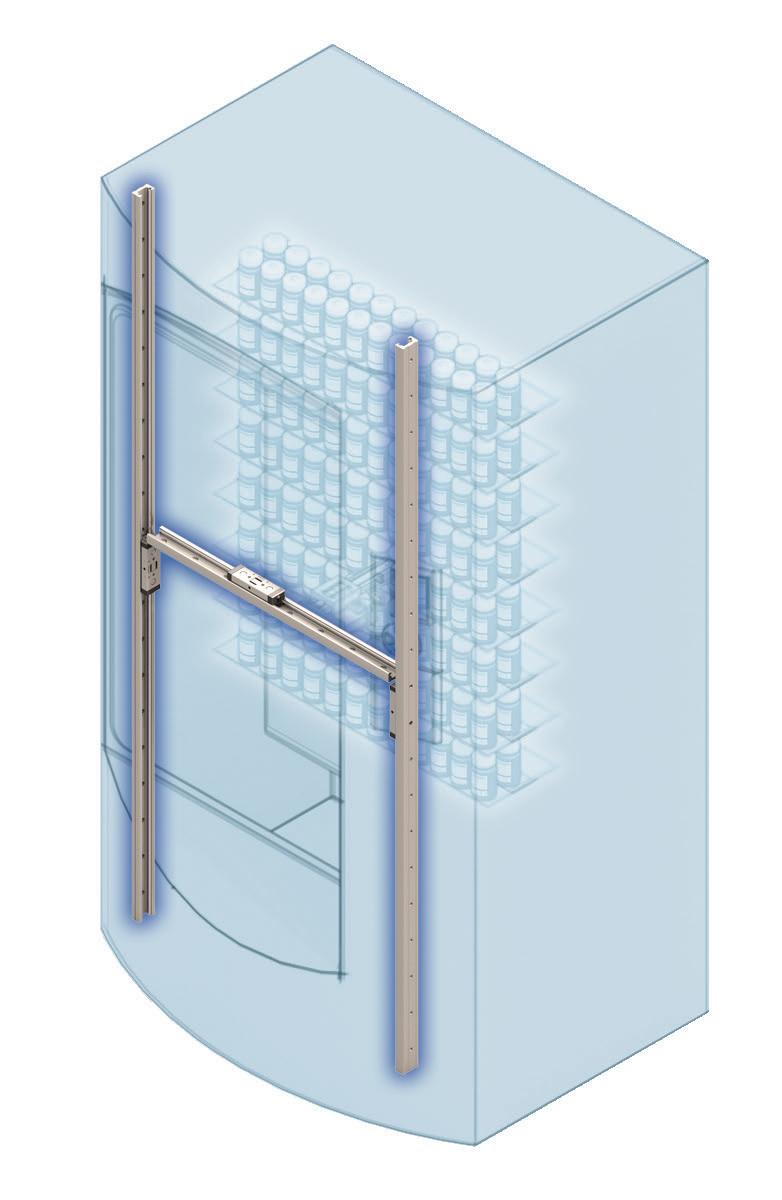
A South African manufacturer and supplier of concrete brick-making machines has started using Vesconite Hilube linear bushings as spare parts for its manual/electric brick-making machines and as standard components in its range of manual brick-making machines.
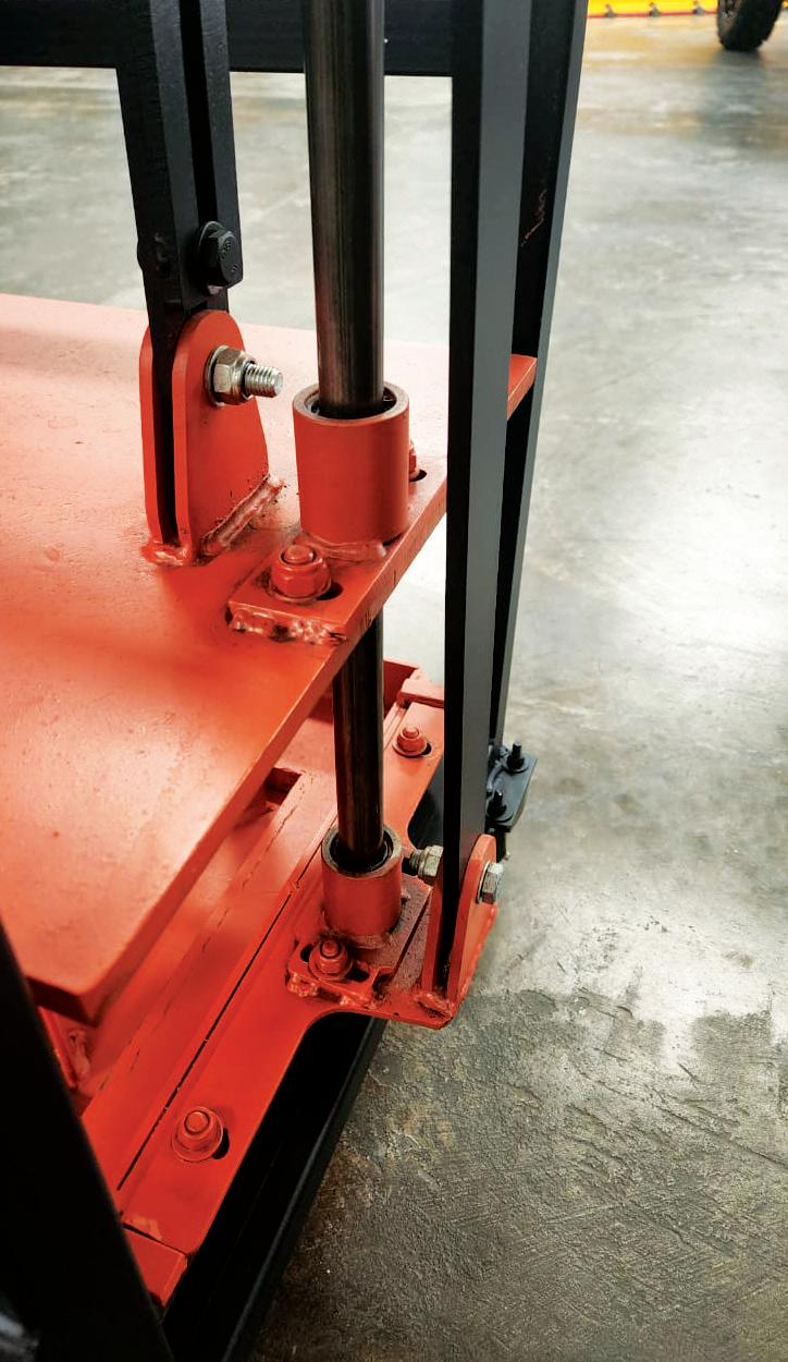
The Vesconite Hilube wear-resistant selflubricating bushings are installed on the shafts on which the tamper guide system moves to compress the concrete aggregate to produce bricks.
Vesconite Hilube has become a standard feature in the manually operated brick-making machines produced by the company. These machines cater to entrepreneurs and startup companies requiring low-output production, where reliability and ease of maintenance are paramount. Each hand-operated machine, known as an egg layer, incorporates eight Vesconite Hilube bushings, ensuring optimal performance and longevity.
Vesconite Hilube bushings are also offered as replacement bushings for the manual/electric brick-making machines that the brick-machine company sources from elsewhere. Supplied with steel bushings initially, the company offers Vesconite Hilube bushings as replacements, recognizing their superior performance, longevity, and good availability. These machines, equipped with 16 Vesconite Hilube linear bushings, cater to higher production demands.
The decision to adopt Vesconite Hilube bushings stems from their many advantages.
Foremost among these is the simplicity of installation and replacement. Traditional steel bushings supplied with manual/electric machines are prone to breakage, particularly during removal. Vesconite Hilube bushings have streamlined maintenance procedures because of their ease of installation and removal. They also minimize downtime since they are fit-forpurpose and include holes for the screws that attach the bushings to the blocks that are placed on the four shafts on which the tamper guide system is located.
Moreover, these bushings demonstrate remarkable resistance to wear and tear, a crucial
TOP: The Vesconite Hilube wearresistant self-lubricating bushings are installed on the shafts on which the tamper guide system moves to compress the concrete aggregate to produce bricks.
LEFT: The hand-operated brick machines that use eight Vesconite Hilube bushings.
requirement for brick-making machines exposed to harsh environments in which cement and dust are found. Operators are encouraged to clean the machines before and after shifts, but where this does not occur, maintenance challenges are increased and are more effectively managed where Vesconite Hilube bushings are in place.
The transition from steel bushings to Vesconite Hilube has also mitigated the issue of accelerated wear on shafts caused by metal-on-metal friction. In the past, this wear and tear necessitated shaft replacements, incurring additional
costs and operational disruptions. With Vesconite Hilube in place, the brickmaking machine supplier anticipates improving the durability of both bushings and shafts, translating into long-term cost savings and enhanced operational efficiency.
Collaboration between the brickmaking machine supplier and Vesconite Bearings, the supplier of the bushings, has been ongoing for several years, facilitating continuous improvement in bushing design and performance. With each iteration, the bushings have become increasingly snug on the shaft, promising
further machine efficiency and reliability enhancements.
The brick-making machine supplier acknowledges the varying degrees of wear experienced on their clients' machines, depending on usage and maintenance practices. However, the company reports no bushing-related issues since Vesconite Hilube bushings were introduced. DW
Vesconite Bearings vesconite.com
The transition from steel bushings to Vesconite Hilube has also mitigated the issue of accelerated wear on shafts caused by metal-on-metal friction.
• EDITED BY MIKE SANTORA
New conveyor pulleys roll out in airports, warehousing
ProVeyance Group has launched its new ProSeries Pulleys so engineers and maintenance professionals who design, operate, or repair conveyance systems can have better performing, longer-lasting applications. The ProSeries Pulleys include head and tail pulleys as well as idlers for the baggage, material handling, and parcel markets.
The ProSeries Pulleys are well-suited for conveyance systems at airports, warehouses, and other applications for safely and efficiently moving products. The new pulleys measure up to 9-in. (23 cm) in diameter and 60-in. (152 cm) in length. Many of the conveyor pulleys on the market include shafts with welded hubs. After enough cycles and flexing in
the pulley’s shaft, the welds can fail. In contrast, the ProSeries Pulleys use either quick-detachable (QD) hubs or hubs with a tapered bore bushing and locking collar. ProVeyance also takes TIR measurements at several locations and balances the pulleys at the desired RPM range to ensure a long-lasting component. Depending on the application, the ProSeries Pulleys come with various shaft materials including cold rolled 1018 or 1045 steel with a higher carbon content.
“We work with customers and if one of our new pulleys doesn’t already exceed a spec, we can design a new one as a replacement for an OEM part,” adds Webster. “As another level of precision, we offer TGP steel for a precision fit in
pillow block bearings and other mounting solutions. We keep a lot of inventory and can meet short lead times.,” said Adam Webster, vice president of Engineering & Innovation for ProVeyance Group.
“As part of our portfolio we make a lot of conveyance components like tapered rollers for OEMs; we’ve been called to make pulleys, too, but we always treated them as a one-off project,” said Collin Sullivan, vice president of Marketing. “Requests kept piling up, so the demand was an opportunity to design and manufacture a full product line of betterquality pulleys, in less time. We dived in with the ProSeries.” DW
Woodsage woodsage.com
The ProSeries Pulleys are well-suited for conveyance systems at airports, warehouses, and other applications for safely and efficiently moving products.
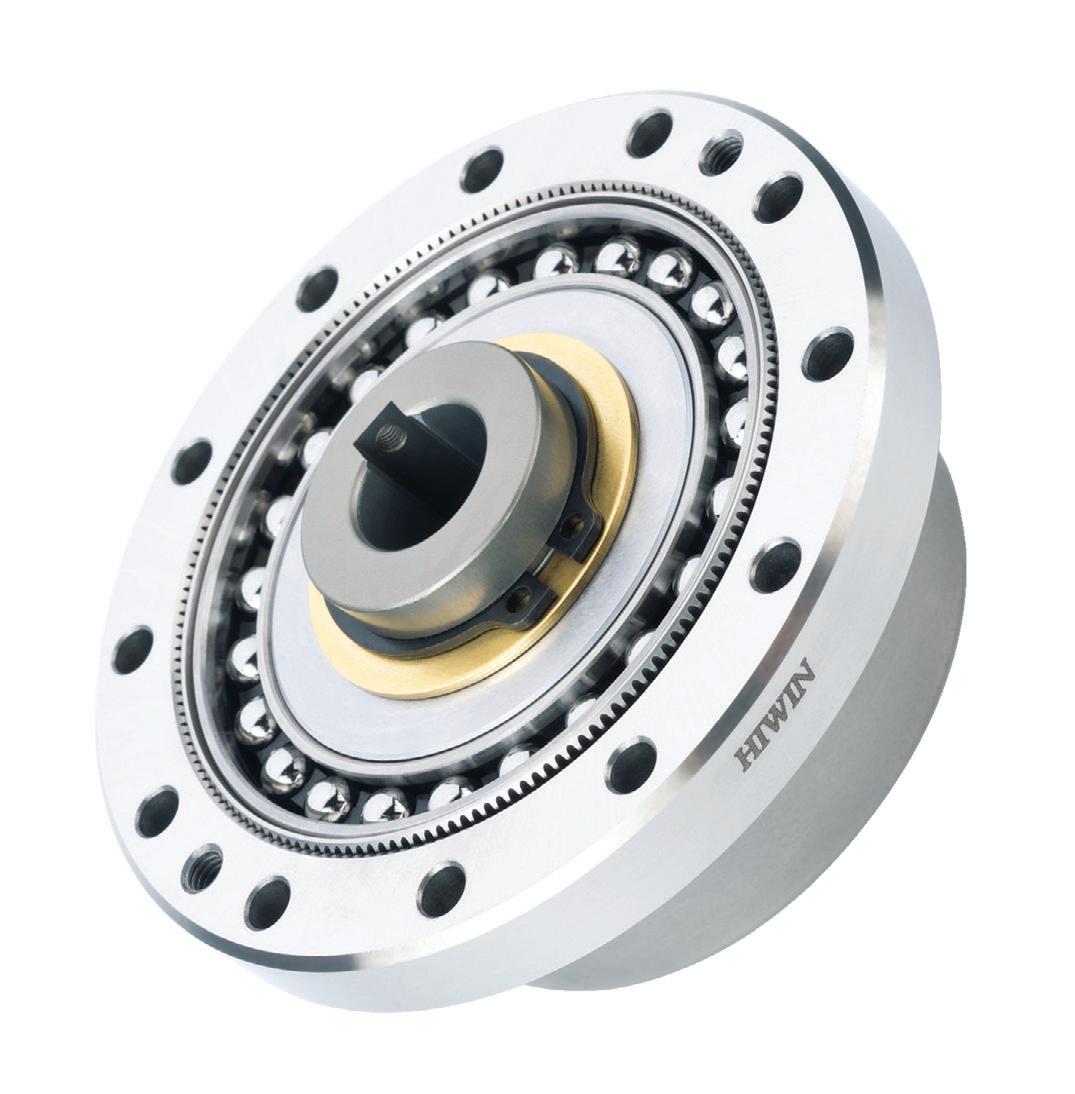
DATORKER® STRAIN WAVE GEARS
AVAILABLE IN STANDARD, HEAVY LOAD, AND LIGHTWEIGHT CONFIGURATIONS, OFFERING HIGH PRECISION, EFFICIENCY, TORSIONAL RIGIDITY, AND LOW STARTING TORQUE.
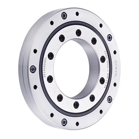
LIGHTWEIGHT AND COMPACT DESIGN, EASY TO INSTALL AND MAINTENANCE, VARIETIES OF BEARING TYPES AND SIZES FOR SOLUTION.
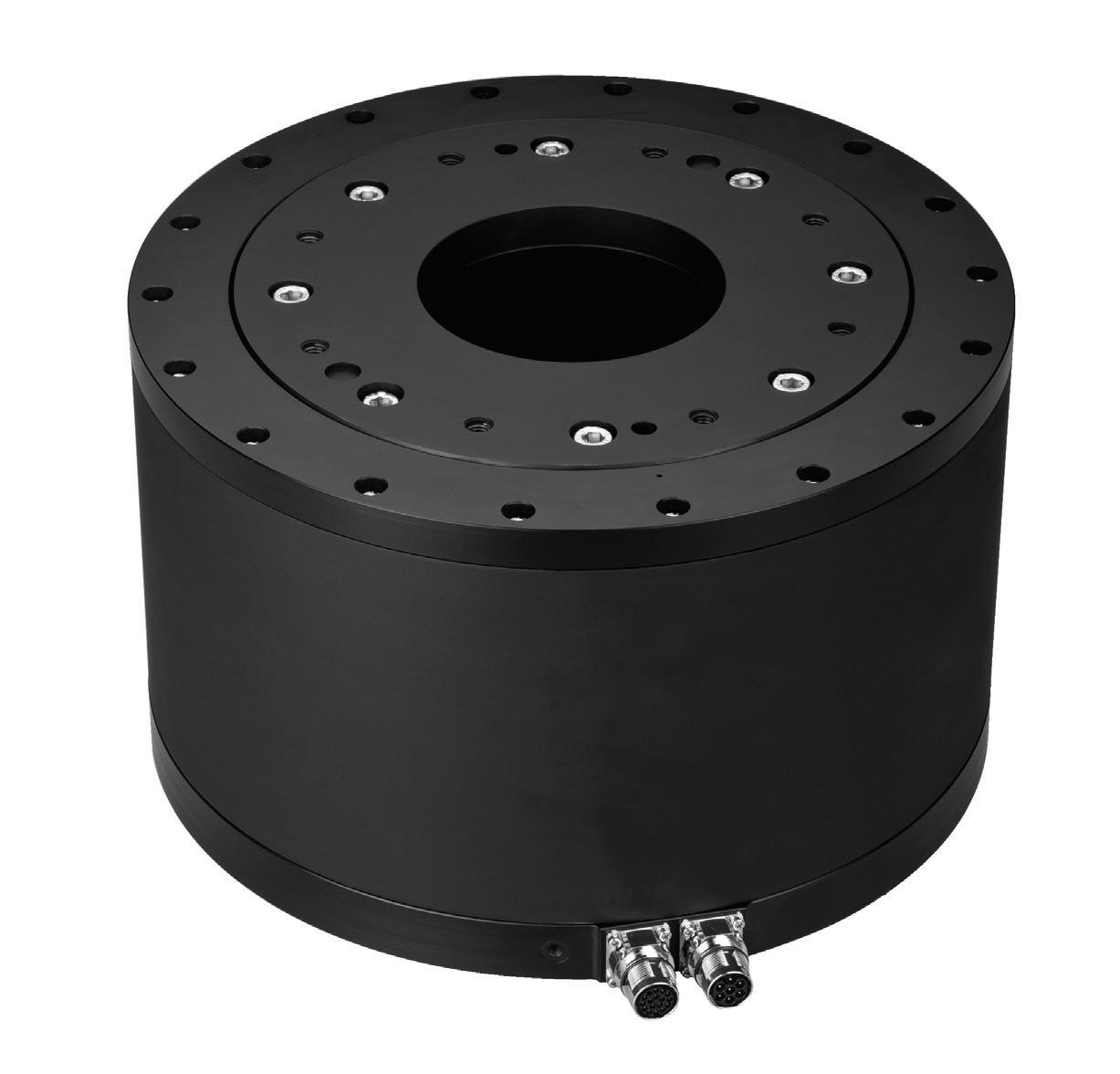
EQUIPPED WITH A WATER-COOLED TORQUE MOTOR, HIGH-PRECISION BEARINGS, ANGLE ENCODERS, AND A POWERFUL BRAKE SYSTEM.
ENGINEERS ON-SITE TO ASSIST IN FINDING THE IDEAL SOLUTION.
• BY MARK HAMPTON
MANAGER
Bearing considerations for offshore wind platforms
Wind power is the most developed alternative energy source globally with growth driven by rising fuel prices, an increasing concern for the environment, and a need for countries to enhance their energy security. After nearly 40 years, installed wind power capacity reached a milestone of one terawatt (TW) worldwide in 2023 and global policies are driving this towards two TWs by the end of 2030.
Clean electricity produced by wind power plays an important role in the future of sustainable energy. Wind turbines are key in working toward the International Energy Agency’s goal to reach net zero emissions by the year 2050 and limit the global temperature rise to 1.5° C2. The energy sector must balance its CO2 emissions so there is no overall increase in the atmosphere which is one of the factors driving a significant increase in wind power investments.
Offshore platforms take advantage of higher wind speeds and greater wind consistency, generating more power than onshore turbines. Constructed on platforms tethered to the seabed, they potentially allow for an even greater number of turbines in deeper waters further offshore. All the leading floating foundation concepts for offshore wind turbines require mooring to the seabed.
Mooring systems are comprised of mooring lines, anchors, and connectors. They keep ships and floating platforms stationary on the surface in all water conditions. Selecting the optimal materials to construct these long-lasting, environmentally sensitive, and efficient offshore wind platforms is critical.
The bearing components in offshore wind platform mooring systems must be dimensionally stable, have minimal environmental impact, be durable with
Clean electricity produced by wind power plays an important role in the future of sustainable energy. Wind turbines are key in working toward the International Energy Agency’s goal to reach net zero emissions by the year 2050 and limit the global temperature rise to 1.5 °C2
long service life, and have minimal negative impact on adjacent parts. Original equipment manufacturers (OEMs) of offshore floating platforms should work with a components partner that offers a solution with low wear rates during continuous operation while enhancing the performance of the fairleads and tensioner risers.
Trelleborg’s Orkot composite bearing materials are well-suited for demanding high-load applications like offshore wind platforms. Orkot C620 has an outstanding ultimate compressive strength of 470 newtons/square millimeter (N/mm2). The design limit of 400 N/mm2 allows engineers to meet the ever-increasing needs of larger wind turbines and platforms. In the mooring system, Orkot C620 provides a strong bearing material with excellent impact strength to protect against shocks, has very low swell (<0.1 percent) and excellent dimensional stability.
Tell me moor
Fairleads: A fairlead is a device used to guide ropes, wires, or chains to control their direction without chafing or excessive wear. In a mooring system, fairleads are typically located at the surface side of the mooring system and mounted on the offshore wind platform. Low-wear radial bushes and thrust washers are needed in fairleads to help ensure continuous operation without compromising performance. A lowfriction bearing material with excellent stick-slip properties will ensure smooth running with no sudden release or whipping of the mooring lines.
Tensioner risers: A tensioner riser is a mechanism used to apply a controlled force to the mooring lines, compensating for changes in environmental conditions such as waves, currents and wind
which can cause variations in tension. Tensioner risers help keep the moored structure in a stable position and require wear rings to ensure smooth movement, reduce wear, and decrease maintenance.
Mid-water arches (MWA): Mid-water arches support the mooring lines of floating structures such as offshore wind platforms. The connections holding the arches in place require a highperformance bearing to ensure the arch can move as designed and help prevent galvanic corrosion.
Spreader bars: A spreader bar is a structural element that helps distribute loads over a wider area, reducing stress concentrations on the mooring system. Spreader bars provide multiple attachment points for mooring lines, improving the overall stability and load distribution of the mooring system.
Padeyes: Often used in conjunction with spreader bars, padeyes are reinforced metal fittings or brackets welded or bolted onto the mooring structure, providing secure attachment points for lines, rigging, or lifting equipment. Padeyes require bearing solutions with a very low coefficient of friction allowing smooth operation at high loads and low speeds.
A lasting solution
Orkot bearings were fitted in 1998 into mooring line links for a floating production storage and offloading (FPSO) unit in West Africa. In 2023, after 25 years of permanent use underwater, the top parts of the spiral strand wires of the mooring line were recovered and inspected. After examination, the operator determined that the original
bearings were still in excellent condition and fit to extend the life of the FPSO unit.
Orkot TLMM bearings were originally chosen as the impregnated fillers in the material to provide a low-friction bearing surface and exhibit little wear when submerged in water. TLMM has a high load capability and does not promote corrosion on the counter faces, helping it to protect not only the hardware but the bearing itself.
Key considerations for floating offshore wind power materials
• Dimensional stability — will materials change with time and in response to environmental conditions, e.g. do they swell in seawater?
• Environmental impact — will materials avoid any negative impact on ecosystems and the environment, e.g. do bearings require lubrication and grease that can leak or leach?
• Effect on adjacent parts in the system — will materials contribute to corrosion or wear; is cathodic protection provided?
• Service life — will materials last for the system lifetime; are they low wearing and long lasting?
• Durability — will materials perform in harsh environments and resist prevailing temperatures, seawater, grit and contamination? DW
Orkot • orkot.com
Motion-PLC from Trio Motion Technology combines motion, robotics, and logic in one package, reducing the cost and complexity of machine design.
Miles Budimir Senior Editor
PLCs in control
PLCs (programmable logic controllers) have long been the go-to control technology for a range of control applications. They can be found in practically every kind of application across most industries and manufacturing processes; from agricultural machinery and medical equipment to automated test setups, as well as on many different types of machines.
Over time, PLCs have gotten smaller and costs have dropped, making them more attractive options not only for
machine control but many other types of applications where previously there were either size or cost restrictions.
PLCs continue to be robust options for many types of established and emerging control duties. And they continue to evolve as PLC suppliers offer more features and simplify integration into machines.
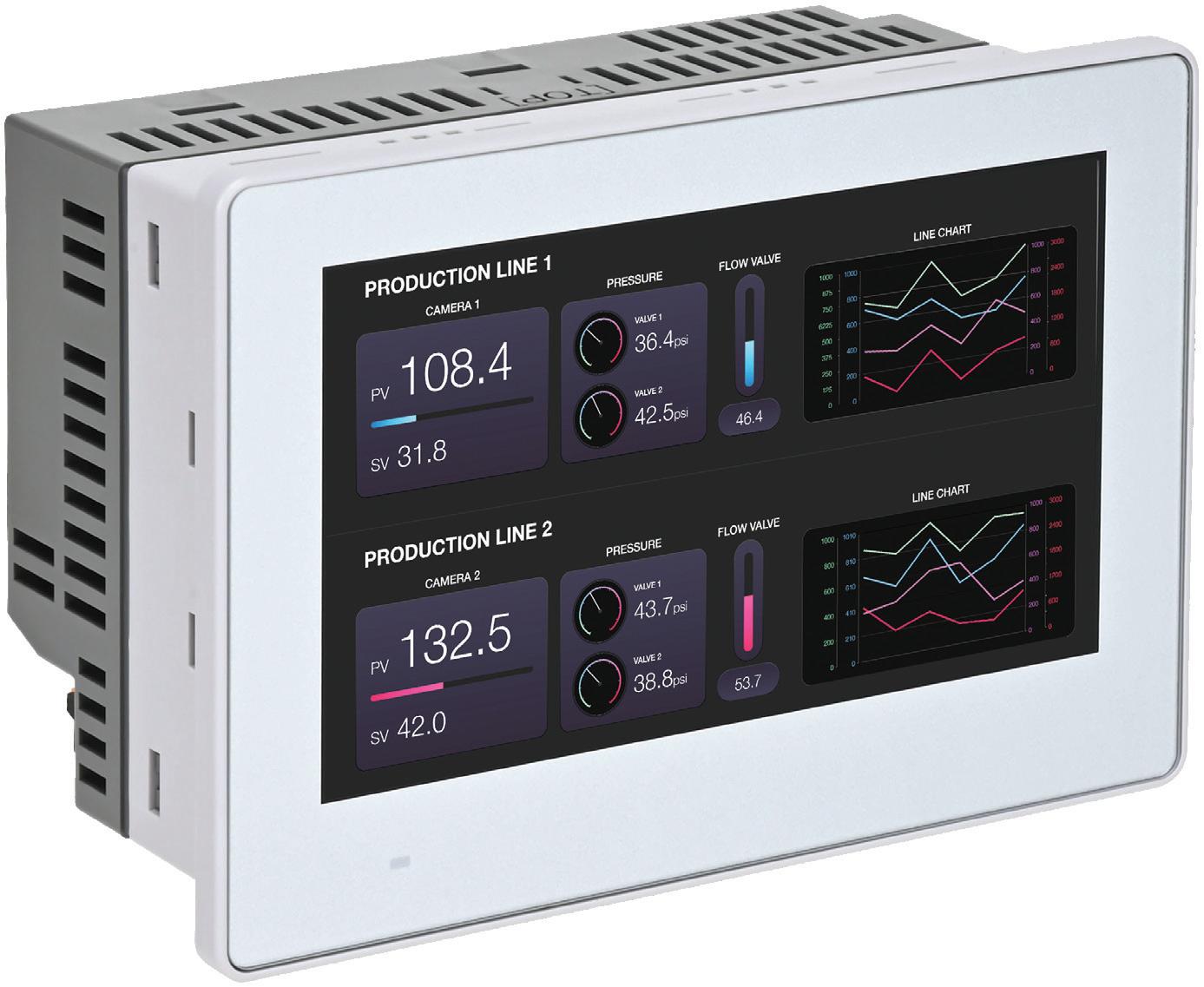
Combination PLC+HMI
One example of integration comes from IDEC, where the company has updated its SmartAXIS touch family with the new
FT1J Series combined PLC+HMI. This device combines a built-in full function controller, both onboard and expandable I/O, and a 4.3-in. touchscreen display, in a compact all-in-one form factor that is rightsized for visualizing and automating a wide range of applications.
Integrating a PLC and HMI has a number of benefits. For one, an all-inone PLC+HMI requires far less panel door and interior space than individual devices. The unit’s thin bezel provides the greatest possible display area compared with its installation footprint,
and the entire package requires only a shallow mounting depth clearance. Installation is simplified because the PLC and HMI are internally connected, share the same network connection, require only one power supply (and consumes less power than individually separate PLC and HMI installations), and all connections use push-in wiring connectors. The FT1J is also ready to use and communicate right out of the box. End users configure the PLC+HMI with an intuitive and integrated development environment for both PLC and HMI functions, providing significant configuration and programming efficiencies.
The integrated PLC and HMI each have their own dedicated CPU and user memory for optimized scan time performance, and they communicate natively with each other. Built-in I/O includes 8 points of dc inputs (configurable as all discrete, or 6 discrete and 2 analog 0-10 Vdc or 4-20 mA 12-bit). Discrete inputs can operate as high-speed counters up to 20 KHz, with a maximum of 4 points of single-phase and 1 point of two-phase. For discrete outputs, a relay version provides 4 points of 2 A relay outputs, while a
transistor version provides 4 points of 0.5 A transistor outputs. The transistor version also provides 2 points of 0-10 Vdc or 4-20 mA analog outputs. Built-in transistor outputs are also pulse capable up to 200 KHz.
The FT1J supports up to two expansion cartridges of discrete or analog I/O, in a variety of configurations and including a 2-point RTD/ thermocouple analog input version. All analog inputs and outputs are 12-bit resolution. Also, designers can use the Ethernet port and the SX8R Bus Coupler to provide expanded amounts of remote I/O.
The HMI’s projected capacitive touch panel (PCAP) advanced technology— similar to that used for smartphones and tablets—saves space and improves performance, while providing 480 x 272 resolution and 16 million colors. Besides being water- and scratch-resistant, PCAP is responsive and resists false signals when dirt or water droplets are present on the HMI face. Fewer touchscreen layers and better light transmission ratings mean less backlight power is needed, and the display provides 500 cd/m² brightness level and 50,000hour backlight life. In addition to being
This PLC+HMI combination from IDEC requires less panel door and interior space than individual devices, reducing footprint in space-critical machine designs.
multi-touch, users can interact with the touchscreen HMI while using thin gloves. Two USB-A ports support flash drives for data logging, recipes, and program transfer—along with dongles for speakers, Wi-Fi, and Bluetooth. The embedded Ethernet port provides users with easy access for remote maintenance and communication, and the Modbus TCP/ IP, BACnet IP, EtherNet/IP, and MQTT protocols are supported for connecting with other intelligent devices. The built-in RS232C and RS422/485 serial communication ports support Modbus RTU and allow the FT1J to communicate to other serial PLCs or devices, like barcode readers or temperature controllers. A main FT1J can operate up to 15 other IDEC HMI devices over the serial port using OI Link communication, which simplifies wiring and reduces communication loading.
Combining motion and logic
For applications combining traditional automation with multi-axis coordinated motion control, PLCs with built-in motion features are a good fit. One example is Motion-PLC from Trio Motion Technology which combines motion, robotics, and logic. It combines advanced motion control performance with the functionality and simplicity of a PLC to reduce the cost and complexity of machine design. The new controller combines multi-axis motion control and IEC language programming with Trio’s new MS I/O system for flexible I/O expansion.
Motion-PLC is available in six models to control a range of stand-alone machines, from two to 16 axes, including robotics integration. The Motion-PLC range is for applications that need motion control and machine logic, such as gantries, packaging, and glue laying. Control engineers can integrate Trio drives, motors, HMI, and SCARA robots, as well as Modbus TCP, PROFINET, and Ethernet/IP devices for a complete machine automation solution.
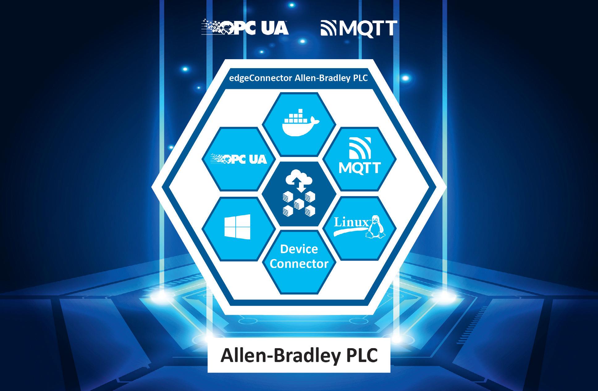
Devices like the edgeConnector product family address the growing need for integration interfaces in software that can be operated on standard hardware and managed efficiently.
All Motion-PLC models include Trio’s new MS I/O system, providing compact and robust I/O expansion through a slice interface. MS I/O slices connect directly to all Motion-PLC controllers, allowing up to 16 I/O slices that combine digital and analog inputs and outputs. The MS I/O system can be extended further with Trio’s MSEC EtherCAT coupler, allowing additional banks of MS I/O to be connected via EtherCAT.
A multi-tasking operating system allows Motion-PLC to perform motion and logic control in parallel. This optimizes machine control performance by improving data sharing between applications and removing latency of fieldbus communications. Combining motion and logic functions within a single controller also minimizes the requirement for hardware and cabling, reducing cost and footprint while improving reliability.
The controller’s motion capability is built on Trio’s motion-first automation platform, Motion-iX. Motion-iX includes a variety of pre-programmed motion features, from simple point-to-point motion through to complex kinematics and robot control. It also includes a PLCopen motion library, and motion can be programmed in familiar PLC languages based on the IEC 61131-3 standard.
An EtherCAT port allows extensive device integration and control, supporting up to 96 EtherCAT devices. Motion-PLC also offers up to two Ethernet ports supported by an Ethernet switch, enabling application programming plus HMI and PLC protocol support via Modbus TCP, PROFINET IO, and Ethernet/IP. Application development and device integration is managed through Trio’s license-free Motion Perfect software, a single tool for programming and diagnostics.
Motion-PLC removes the footprint required for a separate motion controller or PLC and has also been designed with minimal dimensions. The controller modules measure from just 100 mm high by 23 mm wide by 75 mm deep, while I/O slices are just 12-mm wide. The controllers are DIN rail-mounted, and the I/O slices feature forward insertion for easy access, and their connections enable easy wiring with spring clamp connectors.
Taking control to the edge
On the networking end of things, new devices help ease the integration of PLCs into wider industrial networks. For instance, Softing Industrial’s new edgeConnector integrates AllenBradley controllers into industrial edge applications. The edgeConnector
Allen-Bradley PLC provides convenient access to data from ControlLogix and CompactLogix controllers.
With the new Docker-based software module edgeConnector Allen-Bradley PLC, users can easily connect to their ControlLogix and CompactLogix controllers. The controllers’ data is available on edge devices or virtual environments through OPC Unified Architecture (OPC UA) and Message Queuing Telemetry Transport (MQTT). This enables flexible integration into onpremises or cloud environments without modifying the existing PLC configuration.
The edgeConnector Allen-Bradley PLC is easy to configure locally through an integrated web interface. Alternatively, remote global mass configurations are possible through the Representational State Transfer Application Programming Interface (REST API).
There are now five edgeConnector products available for the most common control systems. Besides the new edgeConnector Allen-Bradley PLC, these are edgeConnector Siemens, edgeConnector 840D, edgeConnector Fanuc CNC, and edgeConnector Modbus. All edgeConnector products can be deployed quickly thanks to containerized technology. They are operated on standard hardware and can be easily managed centrally. The integrated MQTT publisher/subscriber functionality allows IIoT solutions to be set up flexibly. The edgeConnectors support state-of-the-art security standards such as SSL/TLS, X.509 certificates, authentication, and data encryption, giving users a simple and secure way to integrate data from production into innovative and flexible IIoT solutions. DWw
IDEC Corporation www.idec.com
Trio Motion Technology www.triomotion.com
Softing Industrial www.industrial.softing.com
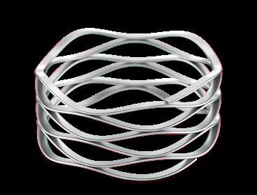
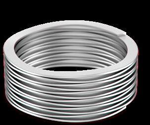
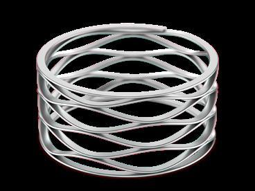
As the inventor of the edgewound wave spring with 100+ years of innovation, here’s why Smalley is The Engineer’s Choice®:
ᘩ 11,000+ standard parts in stock
ᘩ Customizable with No-Tooling-Charges™
ᘩ Trusted performance in 25,000+ applications
ᘩ Award-winning quality backed by leading industry certification
Smalley Wave Springs
ᘩ Same Force, Same Travel as a coil spring
ᘩ Lightweight and compact
ᘩ Diameters from .118” to 120” in 40+ materials
Lisa Eitel • Executive Editor
Stepper actuators benefit from advanced leadscrews
Leadscrews are often used in NEMA-stepmotor linear actuators. Improvements in the manufacture of these leadscrews have led to their increased adoption.
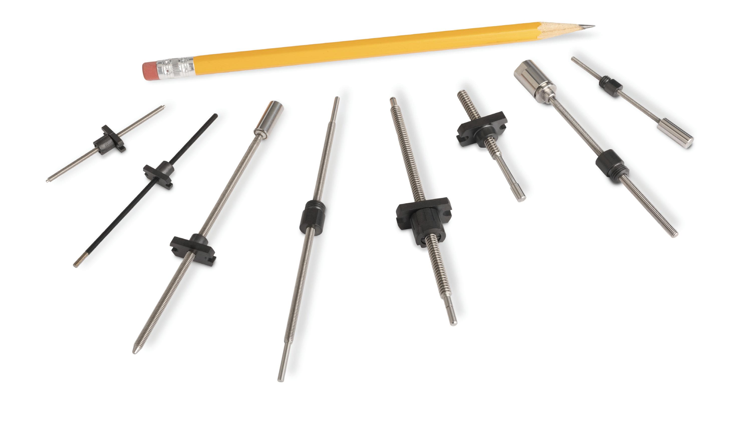
Leadscrews are those threaded rods that allow the travel of a nut via sliding for precise payload positioning. Their fastest adoption in recent years has been in NEMA-stepmotor linear actuators.
More specifically, in medical settings these integrated components impart precise motion to orthopedic devices, ventilation systems, blood analysis equipment, and drug delivery machines. In laboratory applications, these leadscrew-based actuators keeping the drive system small while providing high thrust forces and positioning accuracy — especially useful for specimen analysis, sample-handling stations, chromatography systems, and mass spectrometers.
Yet other key applications include those in 3D printing and certain small-scale CNC machinery; automated vending and kiosk stations; and general inspection stations used in various manufacturing settings.
Automation of leadscrew shaft manufacture
A couple decades ago, it was common for NEMA-stepmotor linear actuators to deliver positioning resolutions within 50 to 100 μm. Now thanks to advanced (and increasingly automated) processes, resolutions to within 10 μm per step are available. The exact capability largely depends on the manufacture of the leadscrew and stiffness of the overall system.
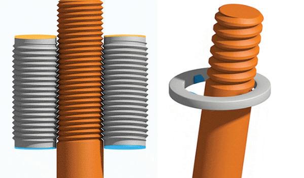
Rolled leadscrews are another key factor here. They’ve become more common over the last two decades — even overtaking machined (or cut) leadscrews in some cases. In short, a steel rod (blank) travels through a station with two or three hard steel or carbide dies. Pressed and rolled between the dies under high pressure, the rod material plastically deforms to conform to the thread pattern imposed by the dies.
What comes out is a durable leadscrew with tight dimensional tolerances and a smooth surface hardened by cold working. That hardening makes for higher load capacity. High surface tensile strength and hardness (compared to those of machined leadscrews) also make these resistant to wear. Due to economy of scale (and no material waste) modern thread rolling has also made rolled leadscrews more cost effective than certain screws that are cut or machined.
Linear Motion
That said, machine-tool technologies related to ground leadscrews have significantly advanced in recent years. There’s also been increased use of socalled leadscrew whirling. This is a kind of proprietary cutting process that makes specialty high-precision leadscrews. Multi-axis CNC machines can now precisely cut threads in one go without complicated setup and alignment. To maintain precision, most cutting tools are carbide, ceramic, or diamond coated. CAD/CAM software and realtime monitoring via sensors optimizes the tool wear and cutting forces and material temperatures to get consistent quality. There’s also been increased use of realtime inspection during machining to confirm thread accuracy and pitch consistency.
Though exceptions abound, ground leadscrews are typically the most cost-competitive option for lowvolume products needing tough power transmission.
Use-specific leadscrew surface treatments
There are an array of surface options on the market for the leadscrews used in NEMA-step linear actuators. Hard chrome plating resists wear and corrosion with high hardness and a smooth low-friction surface. In contrast, cost-effective black-oxide coating is better suited to applications needing
more corrosion resistance and moderate wear resistance.
PTFE coating for precision assemblies can reduce friction enough to preclude the use of lubrication … even while extending nut and screw life. In contrast, nickel plating is good for hardness and dimensional stability on leadscrews that must work in humid settings or cleanroom settings. Elsewhere, in high-load and hightemperature leadscrew applications (especially in aerospace and heavy machinery) the solid lubricant known as molybdenum disulfide excels.
Leadscrew coatings of titanium nitride boost wear resistance while minimizing friction in high-speed assemblies. Anodizing aluminum leadscrews is common in weightsensitive applications — especially for aerospace and mobile robotics. Anodizing imparts an oxide layer to prevent corrosion and wear … and when complemented with PTFE coating makes for a leadscrew with high lubricity.
Yet other options include anti-friction polymer
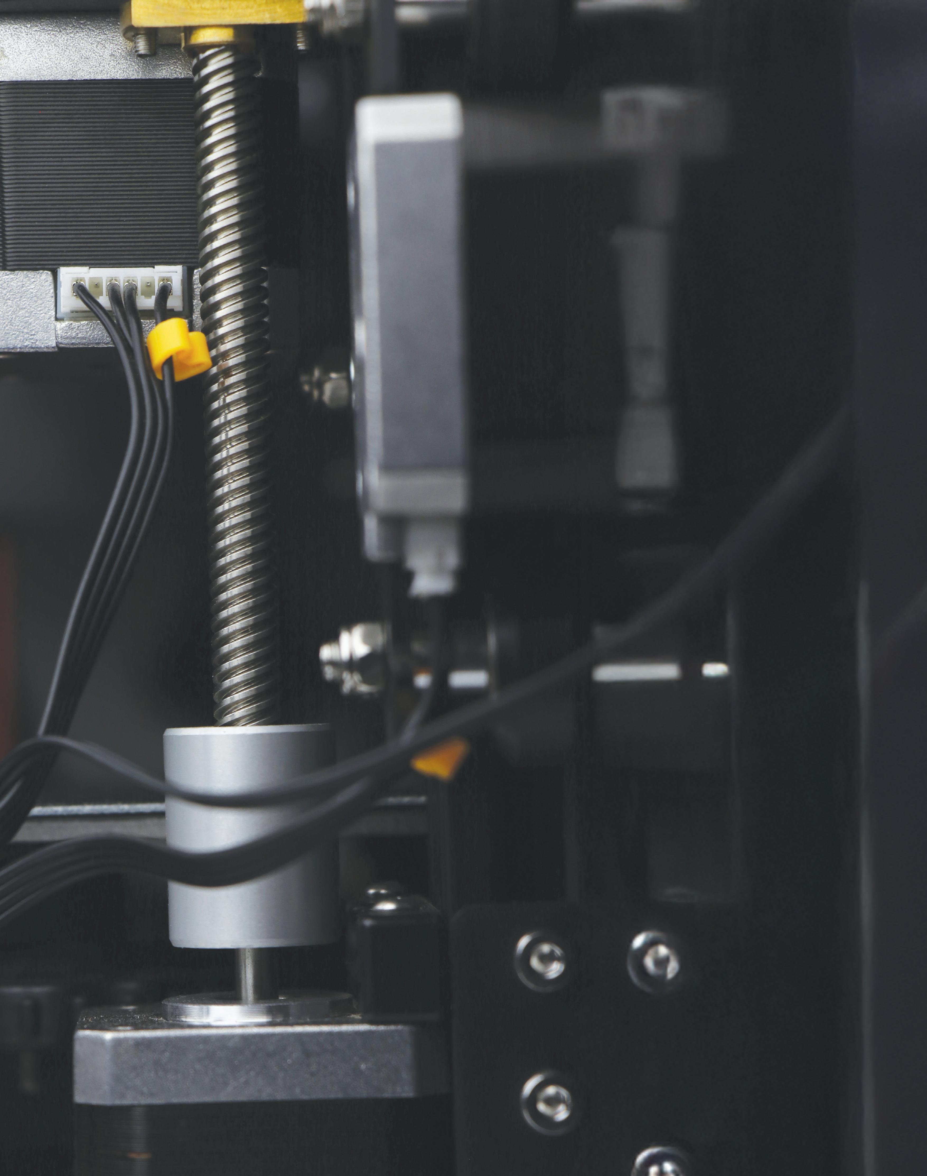
Certain leadscrews from igus are produced through a whirling process.
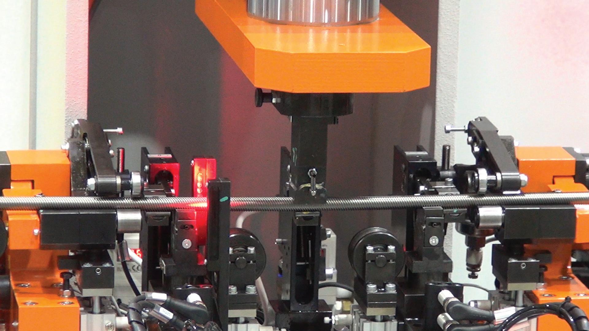
Leadscrew shaft straightness is essential to delivering accuracy and repeatability. Instead of using costly and labor-intensive manual processes (only yielding straightness tolerances to about 0.005 in./ft) PBC Linear employs a Galdabini Pas 4 STEP leadscrew straightener. This highly automated system yields more consistent leadscrews held to within 0.001 in./ft yet produced at higher volumes for a more costeffective component.
coatings that enhance lubricity for selflubrication capabilities. These may be top choices for actuators that won’t get a lot of maintenance but need to deliver long service life.
Other leadscrew elements
We’ve detailed the improvements of the screw shafts themselves. Though beyond the focus of this article, recent years have also seen advancements of other mechanical components. Common now are anti-backlash nuts to maintain actuator repeatability even upon direction reversals. These nuts use springs or compliant sub-elements to hold constant tension against the screw threads.
Leadscrew assembly for higher performance
Pre-integration of leadscrews into NEMA-stepper actuators makes for better overall linear-motion performance.
In the first of three options, called captive linear actuators, the leadscrew nut is integrated directly into the motor. The screw is connected to a spline shaft, so when the motor turns, the screw is prevented from rotating. That means linear motion is produced, allowing the screw to EXTEND and RETRACT from one end of the assembly.
In noncaptive linear actuators, the screw nut is integrated into the motor — or mounted to the face of the motor … so it doesn’t travel along the screw. Instead, the screw is prevented from rotating typically by the attached load. When the motor and nut turn, the screw travels back and forth “through” that motor-nut combination. Alternatively, if the screw is fixed so that it doesn’t travel, the assembly essentially becomes a driven nut design. Here, the motor’s rotation causes the motor-nut assembly to travel back and forth along the stationary screw.
Finally, external linear actuators are the sort of the stereotypical stepmotor actuator that many picture. Many of these actuators include a motor with a hollow shaft to physically attach one end of the screw. So, the nut is external to the motor. Like a traditional screw-motor setup, the motor’s rotation causes the screw to turn, which advances the nut (and the load) along the length of the screw shaft.
In this classic design, the opposite end of the screw (not attached to the motor) is often unsupported. Being unsupported is acceptable for light loads … and it’s okay short strokes too. However, many applications need support for that distal end of the screw, along with a linear guide to support any radial loads. This can get into full linear-stage territory. DW
Thomson Industries Inc. now lets engineers tailor miniature 2, 3, and 4-mm leadscrews for robotics, automation, and medical applications (for example, handheld medical devices including syringe pumps) with an online tool accessible through thomsonlinear.com/ls. Machining and end-support options can be specified, along with drive-end configurations such as integrated motor couplers for rapid prototyping and oversized journals compatible with standard market bearings.
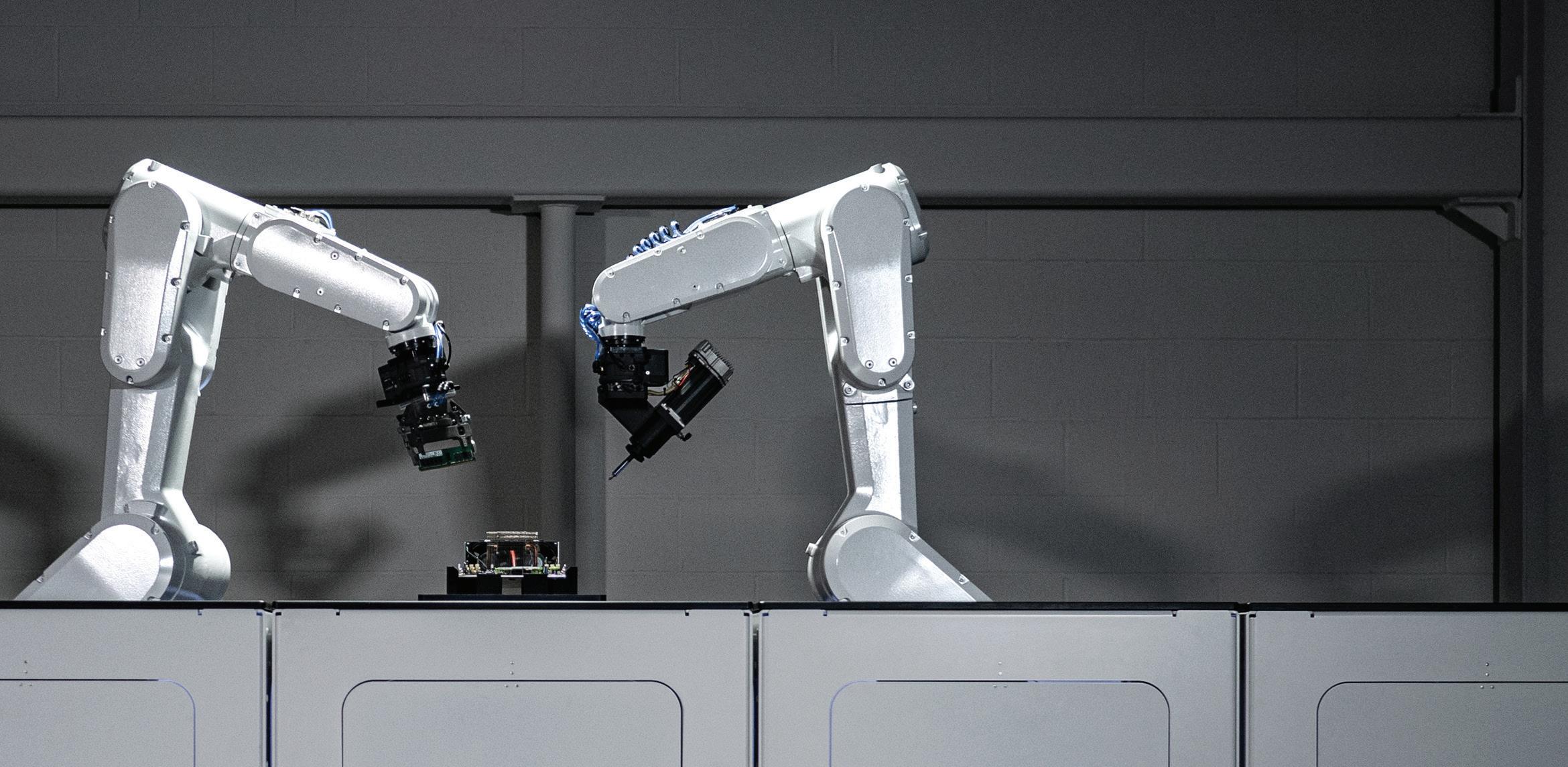
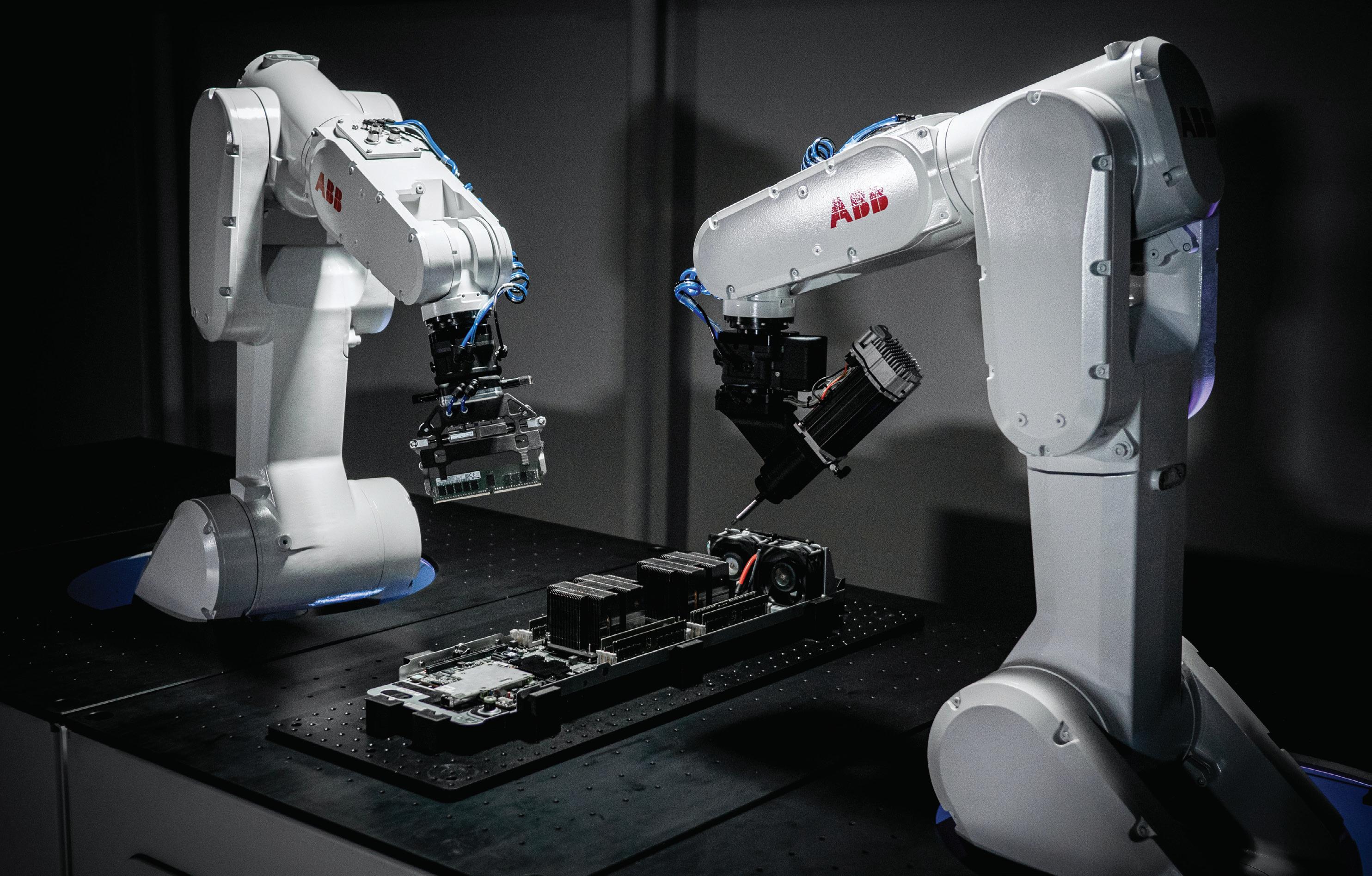
ROBOTIC MICRO-FACTORIES TACKLE DATA CENTER E-WASTE
ABB Robotics is collaborating with US start-up Molg to create robotic micro-factories to recover and recycle data center operators’ disused electronic equipment, commonly known as e-waste. With global e-waste projected to rise to 75 million tons by 2030, the micro-factories will play a vital role in reducing the electronic waste, helping the data center sector operate more efficiently and sustainably.
“Through this collaboration, we continue to realize our vision of helping organizations operate more efficiently and sustainably,” said Craig McDonnell, Managing Director Business Line Industries, ABB Robotics. With Molg, we are creating new applications for industrial robotics in a growing segment with circularity and sustainability at the core. Our solution enables the upgrading and automated disassembly of data
AUTOMATED DISASSEMBLY AND RECOVERY ADDRESSES ENVIRONMENTAL AND REGULATORY DEMANDS AS WELL AS WORKER WELFARE
Edited by: Mike Santora
center equipment, helping to create greater circularity in the data center sector through responsible disposal, recycling, and reuse of components.”
Advances in computing such as AI, machine learning, and the cloud necessitate the need for data centers to upgrade and expand their facilities more frequently. Today, data centers are major contributors to the 2.6 million tons of e-waste generated worldwide each year.
With global e-waste projected to rise to 75 million tons by 2030, microfactories will play a vital role in reducing the electronic waste, helping the data center sector operate more efficiently and sustainably.
ABB Robotics continues to support innovation ecosystems through collaboration and venture capital investments. ABB Robotics & Automation Ventures (ABB RA Ventures) participated with an investment in Molg’s seed round led by Closed Loop Partners’ Ventures Group, alongside Amazon’s Climate Pledge Fund, Overture, Elemental Impact and Techstars Ventures.
Molg was recognized as a winner by ABB’s Motion drive business in its ABB Accelerating Circularity Startup Challenge 2023, Molg’s robotic microfactory can autonomously assemble and disassemble complex electronic products including laptop PCs, servers, and industrial electronics.
As an alternative to manual disassembly, or sending equipment to landfill or incineration, the microfactory solves many of the challenges
associated with the disposal of electronic waste. With end users facing increasing regulations regarding the responsible handling of decommissioned equipment, automated disassembly reduces the risks associated with handling toxic elements that can damage the environment and human health, and releases workers from handling arduous and potentially dangerous tasks.
With many components also containing rare earth elements (REEs), the ability to maximize their recovery through automation also provides an economic opportunity to reuse them in the production of new electronic equipment.
The micro-factory solution is aimed at hyperscalers operating large networks of data centers and IT Asset Disposition (ITAD) companies.
“We are excited to have the support of ABB, a global leader in robotics and automation, as we continue pushing the boundaries of what is possible in circularity and automation,” said Rob Lawson-Shanks, CEO & Co-Founder of Molg. “With this investment from ABB, we can accelerate our work to create more sustainable, circular manufacturing processes for electronics that ensure valuable materials are kept in circulation and enhance supply chain resilience.”
The solution is part of Molg’s wider portfolio that includes design-forcircularity and component traceability software tools enabling manufacturers to create products that can be easily demanufactured and recycled at the end of their life. DW
ABB • abb.com
As an alternative to manual disassembly, sending equipment to landfills, or incineration, the micro-factory solves many of the challenges associated with the disposal of electronic waste.
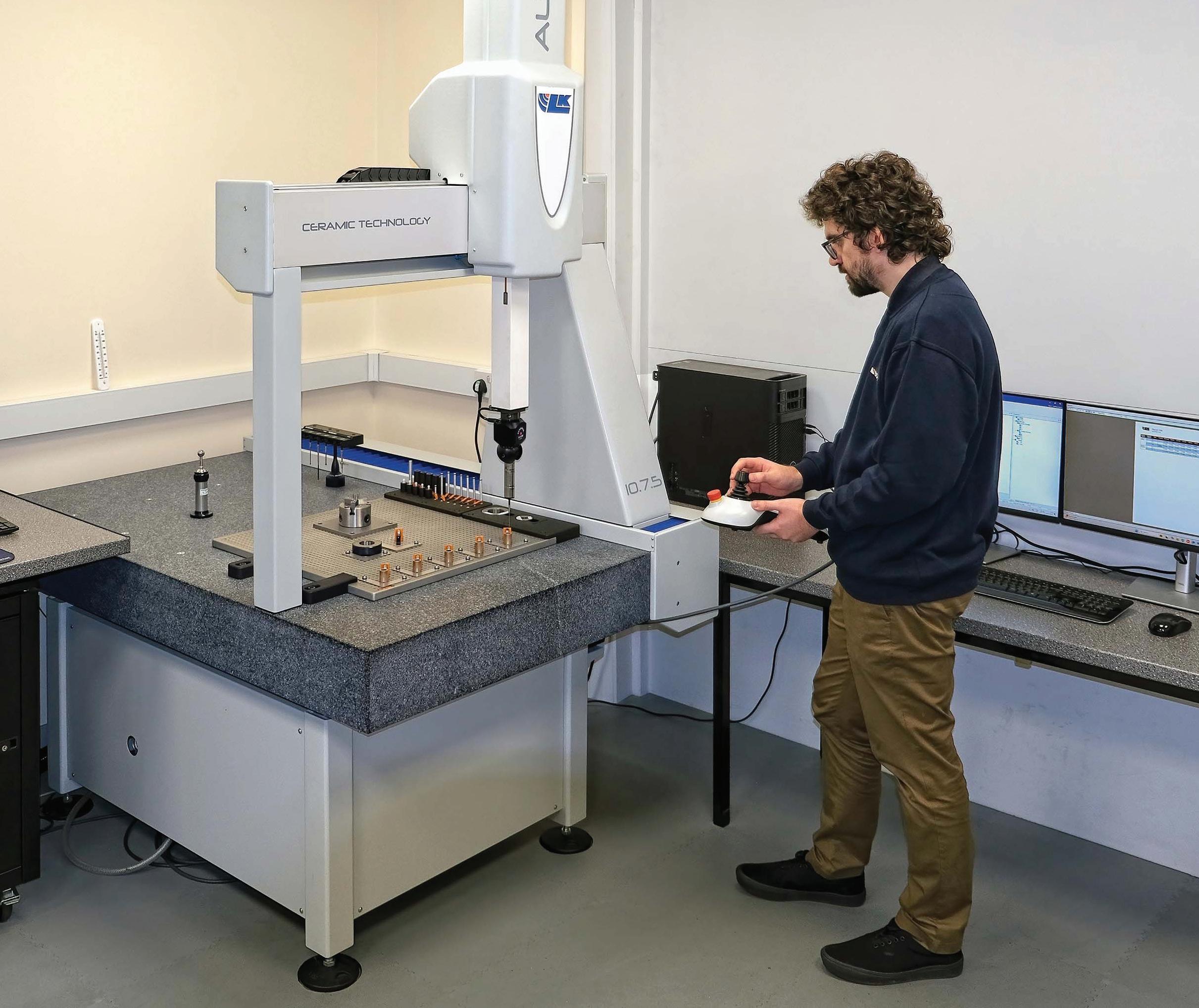
Do these bearings measure up?
Bowman International is an Abingdon-based, UK manufacturer and distributor of bearings and precisionengineered, sintered, and 3D printed components. Bowman International has upgraded the inspection of its products with the purchase of a new coordinate measuring machine (CMM) built by LK Metrology.
Bowman's latest investment comes after decades of continuous growth, mainly organic, but also through strategic acquisitions. The company has seen turnover generated from domestic and worldwide markets increase significantly over recent years, according to managing director Paul Mitchell, who joined the organization some 15 years ago.
Bowman continues to invest in technology and adopt a quality-first philosophy. Part of that progression has entailed the introduction of high precision, safety critical split bearings delivered to the automotive, aviation, defense, marine, and rail sectors, amongst others. The recent acquisition of bearings and housings manufacturer Criptic Arvis, has complemented
Edited by: Mike Santora
Bowman’s established production in its Kingswinford facility, boosting the production and sales of ISO class 7 special bearings, which account for a significant portion of sales.
Unsurprisingly, the amount of work in Abingdon being put onto the previous CMM purchased in 2016 was greatly increasing. However, its level of reliability coupled with a significant increase in product distribution was proving challenging. The equipment was also slow in operation and had basic, timeconsuming reporting, requiring results to be printed out and transcribed to an Excel spreadsheet. After considering potential replacement CMMs from five
Italian machine builders are set to showcase their cutting-edge ‘Breaking Necks’ solutions and technologies
Italian machine builders are the key to unlocking your strategic business potential.
How are end users leveraging Italian machinery to advance their operational goals and address significant industry trends? Machines Italia’s Spring 2025 issue will explore key trends across various sectors utilizing Italian machinery, including advancements in automation, environmental sustainability, and the increasing demand for flexible and adaptable machinery. For more details, visit machinesitalia.org
Metrology
different sources, Mitchell and Bowman's quality manager Owen White chose the LK option, an Altera 10.7.5, after visiting the manufacturer's factory and witnessing metrology trials carried out on sample bearings.
Standard, bought-in products generally need only first article inspection before a batch is delivered to a customer, so the daily workload on the CMM is relatively light. Conversely, bearings produced in-house normally require five to be checked to ensure consistency. This single business area therefore consumes a significant proportion of CMM capacity. Sometimes when carrying out capability studies, 25 to 50 components need to be measured. In one exceptional case, a customer requested 100% inspection of 100 Oilite safety-critical, self-lubricating bronze
bearings, which are exclusively marketed in the UK and Europe by Bowman.
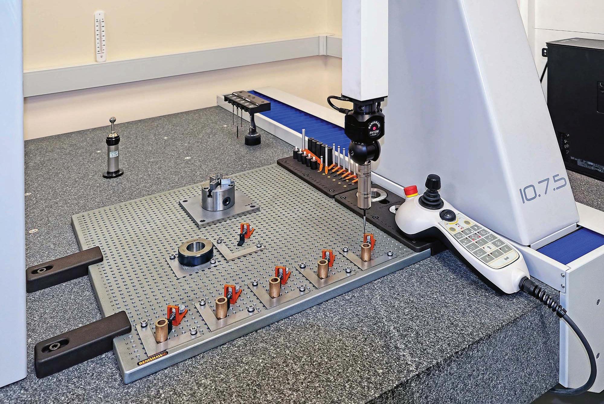
In view of the high accuracies involved, by the time the Altera arrived in early April 2024 the quality control room had been refurbished by lowering the ceiling and installing a new air conditioning unit to enable the temperature to be controlled reliably to 20 ± 1°C. The CMM's accuracy is verified every morning, rather than at the more usual frequency of once a week and then checked using a UKAS calibrated ring gage. The gage and each batch of five manufactured bearing samples are positioned precisely on the granite table using L-shaped, laser-cut retainers attached to a base plate having an array of drilled and tapped holes.
Attached also to the plate is a lathe chuck specially adapted in Abingdon
to hold washers and other awkwardly shaped items securely for probing. To the rear is a six-port probe rack that allows parts to be inspected using multiple probes in a single, automatic cycle. Components to benefit from being measured in this way include tall bearings and complex, 3D-printed plastic components, such as polyamide 11 bearing cages and seals for in-housedesigned and patented split bearings.
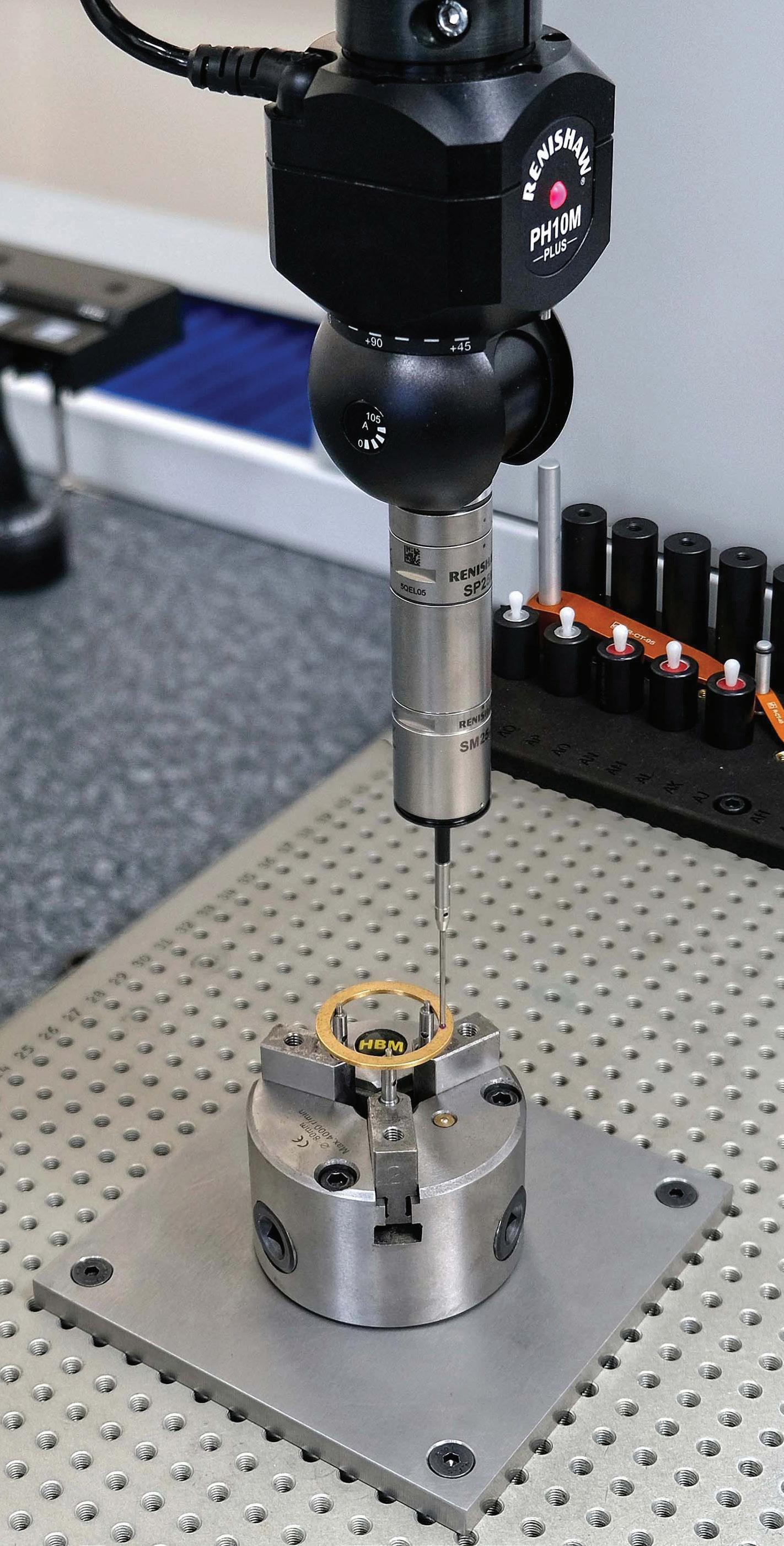
Unlike on the old CMM, which only used touch-trigger probes, a notable difference with the new LK inspection platform is that the manufacturer supplied it with an SP25M scanning probe in addition to various conventional probes, all for deployment on a PH10M Plus motorized indexing head. To enable tactile scanning as well as data analysis and reporting, LK supplied its
Five bearings from each batch being inspected.
own CAMIO 2024 R1 multi-sensor software and 3-axis scanning module interfaced to its NMC300 controller.
As White pointed out, "On one of our 20 mm diameter bearings, for example, we used to measure 12 points around the top and bottom of the ID. We now capture more than 100 points in a shorter time, which gives us a much better idea of not only the accuracy of the part but also the overall form of the bore."
He added that with the multiple sensing capability provided by the indexing head and software, it would be an easy matter to incorporate a laser scanning sensor into the metrology system. That will be advantageous if there is a future requirement to inspect complex parts made in two Hewlett-Packard plastic 3D printing machines on site. Installed in 2018, they regularly provide an additive manufacturing bureau service in addition to building parts for internal use.
Overall, quality control activities at Bowman have been accelerated right along the process chain, whether it is for ID/OD checking, or for verification of concentricity, circularity, flatness, or feature position. Programming in CAMIO takes half the time at between 15 and 20 minutes compared with when the previous CMM was in use and measuring cycles at around five to six minutes are similarly shorter. The LK software also cuts the time for producing inspection reports for customers to typically half an hour, faster by at least a factor of two and up to four times.
White also shared his positive experience undergoing one-to-one training in Castle Donington, which was carried out while the CMM was being installed in Abingdon. Not only was the learning environment excellent, but the individualized nature of the instruction allowed a focus on measuring principles as they apply to bearings, rather than involving general metrology of marginal utility. The standard of knowledge he gained made it easy for him, on his return to Bowman, to train additional staff members.
Mitchell concluded, "We have thousands of product lines and pride ourselves on our comprehensive stock availability, innovation, technical superiority, and next-day delivery.” DW
Bowman’s special lathe chuck.
DESIGN GUIDES
Key technology content produced by the editors of EE World compiled in individual PDFs. Download your free design guide today!
Find these downloadable technical guides in our DESIGN GUIDE LIBRARY, bookmark this site as guides are added on an ongoing basis!
www.eeworldonline.com/design-guide-library
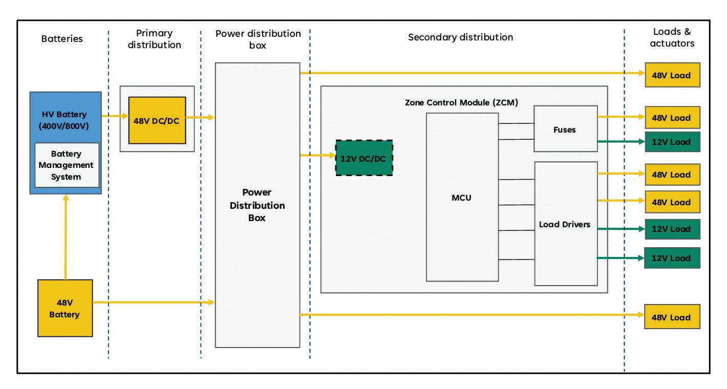
zonal architectures? Why EVs are transitioning to
MICHELLE FROESE • EDITOR
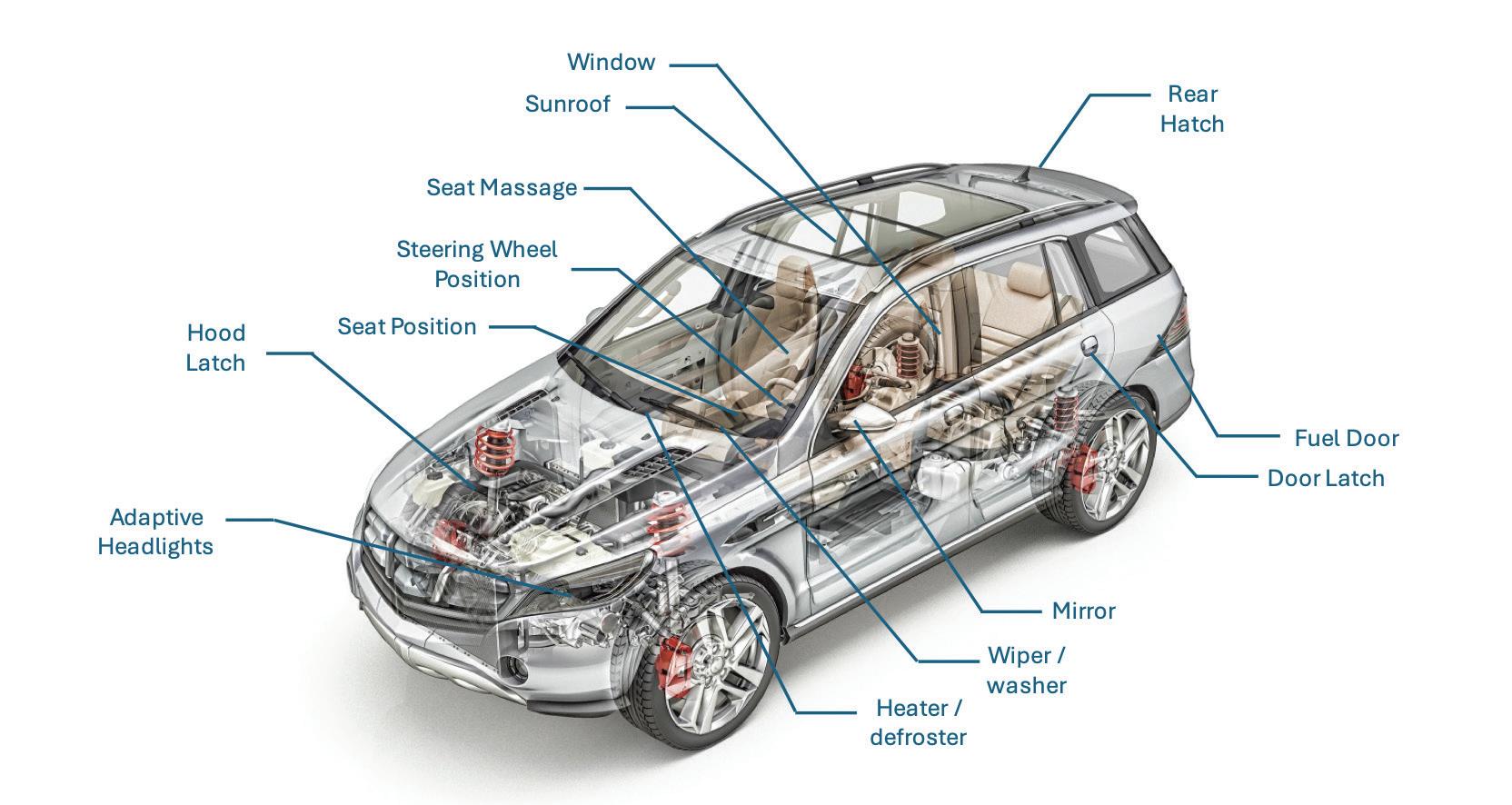
The automotive industry is undergoing a paradigm shift in vehicle design and function, transitioning from traditional distributed to advanced zonal architectures.
By 2030, vehicles with zonal control modules are expected to match those without. Today, some 80 to 90 million cars lack this technology, which will slowly shift closer to a 50/50 split between the two in the next decade.
OEMs are now defining the number of gateways (two, three, or four) required by a vehicle’s central computer and the communication protocols for high-speed data transmission.
But how many gateways are optimal? What type of computer and protocols best meet safety and data needs? And what are the benefits of zonal architecture? Let’s dive in.
What is meant by zonal architecture?
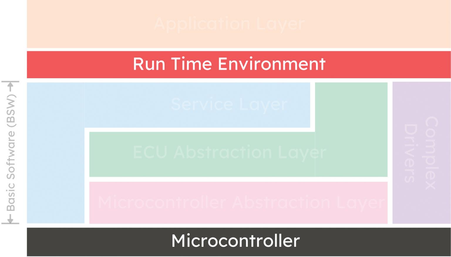
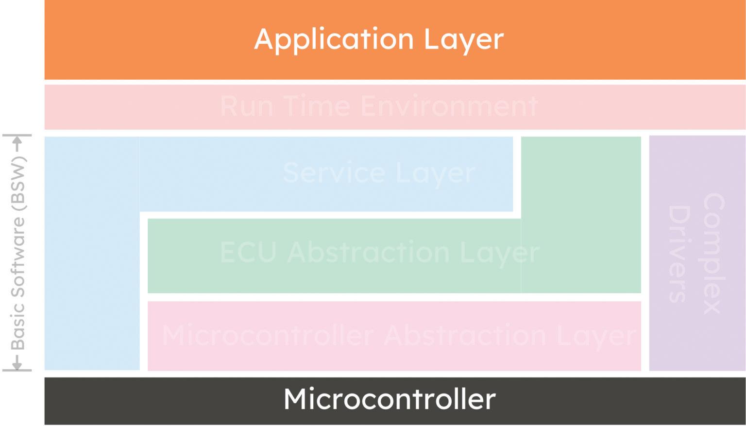
“The zonal architecture is the vehicle’s electrical or electronic, or what we call E/E architecture, that physically
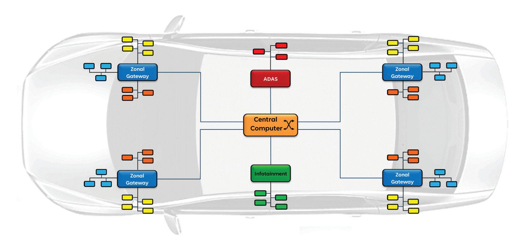
Figure 1. A zonal architecture consolidates functions into specific zones or locations and is controlled by zonal gateways that service many specific functions — such as the ADAS, body, chassis, and infotainment.
consolidates different functions into specific zones within the vehicle,” explains Aaron Barrera, strategic marketing manager with Allegro MicroSystems. “A central computer communicates and controls many of these gateways within an electric vehicle, serving different functions.”
This framework significantly reduces complexity by streamlining communication, power distribution, and system integration, making vehicles more efficient, scalable, and future-ready (Figure 1).
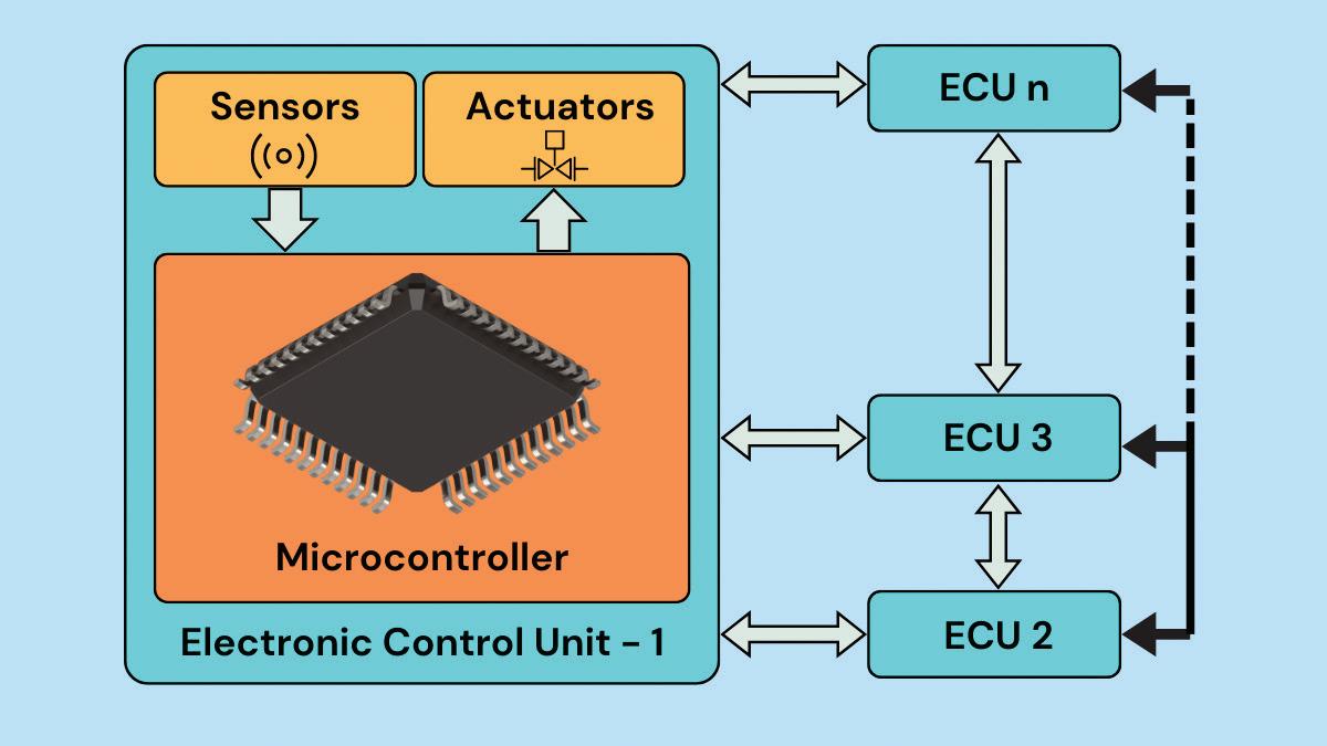
“This is a shift from the earlier distributed architecture, in which several different individual electronic control units, or ECUs, are in the domain architecture,” says Barrera. “In this case, the different functions are typically grouped by domain rather than location.”
Traditional distributed architectures grouped vehicle functions into domains such as body, powertrain, and chassis, each requiring a dedicated ECU. While effective, this system results in numerous ECUs spread throughout a vehicle, leading to a complex web of wiring and power management.
“Now, instead of grouping functions by domain, zonal architectures group systems by location,” Barrera says. “This shift has significant implications for cost, software scalability, and overall vehicle efficiency.”
Zonal architecture organizes a vehicle’s functions by physical location, using centralized computing to manage the gateways within designated zones. Advantages include greater software integration and cost efficiency.
The software-defined vehicle
One of the key drivers behind the adoption of zonal architectures is the softwaredefined vehicle (SDV).
“The software-defined vehicle enables scalability and centralization through a software-based framework — or, as I like to say, a computer on wheels,” says Barrera. “This lets OEMs integrate future technologies and deliver software upgrades without completely redesigning the hardware systems.”
The SDV approach simplifies vehicle design. By clustering multiple functions into
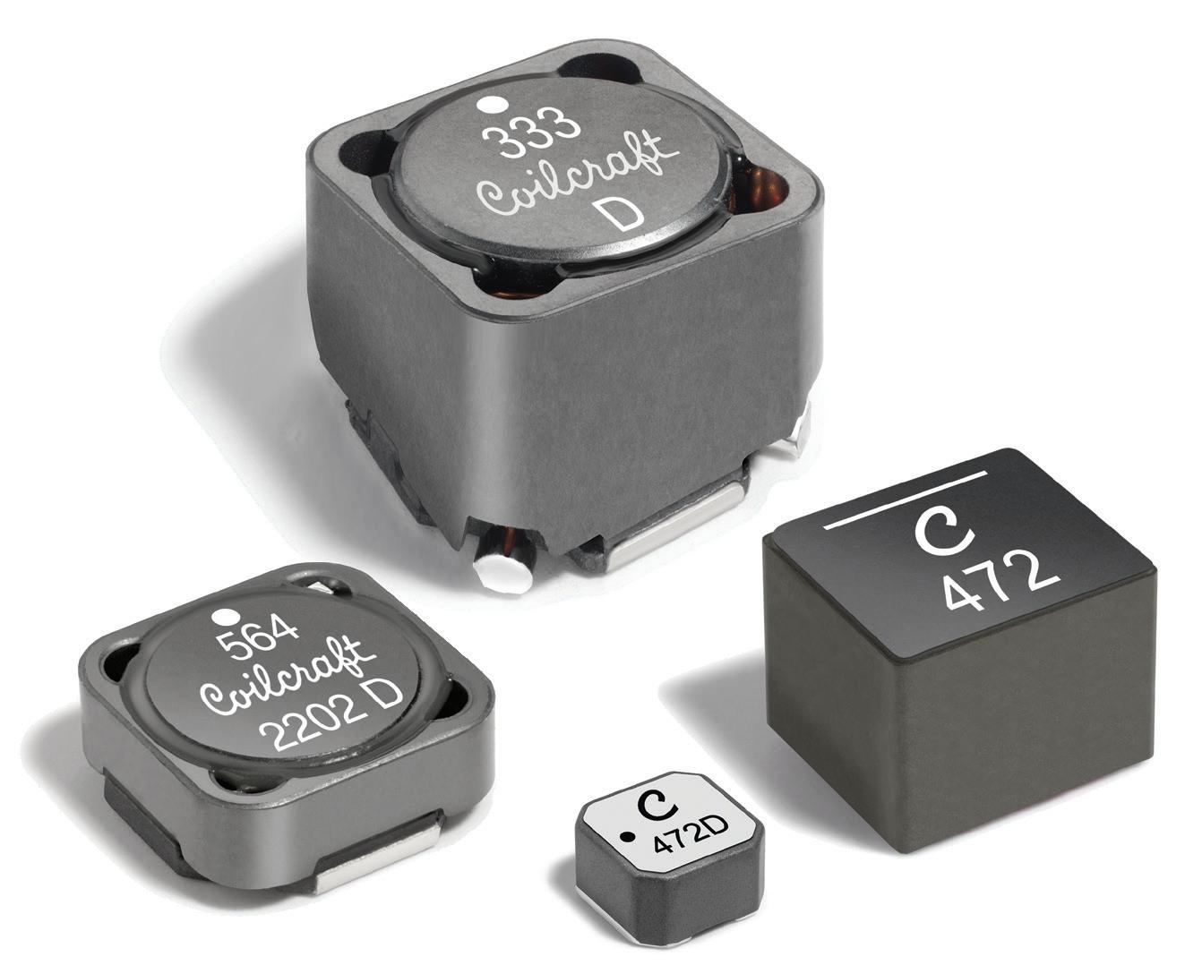
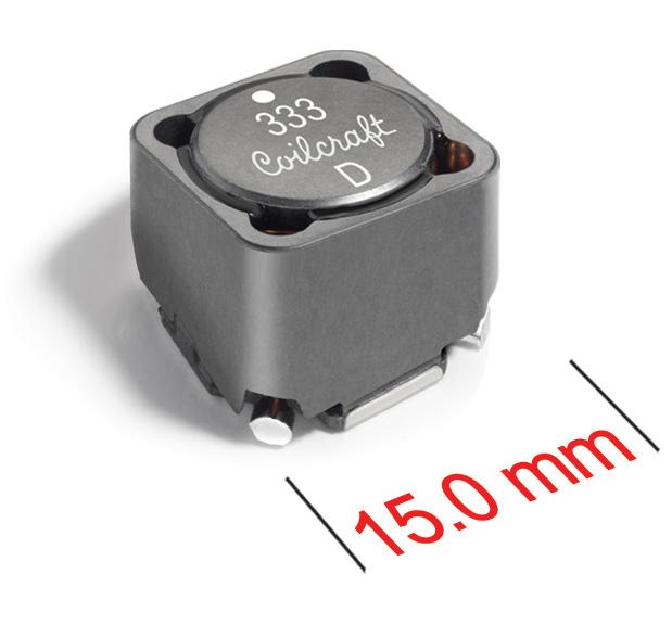
High Voltage Power Inductors
Coilcraft offers a wide range of voltage-rated power inductors that assure the safe, reliable operation of your designs.
Coilcraft voltage-rated inductors support applications such as high-voltage DC-DC and AC-DC power supplies, industrial and home automation controls, appliances, and automotive, including electric vehicles (EVs).
Our XEL and XGL Families of molded power inductors offer operating voltage ratings from 60 V to 120 V, and many of our
LPS and MSS Family inductors are suitable for 400-volt operation or higher.
Our new MSS1514V Series offers an 800 V rating in a 15.5 x 15.5 mm footprint, with excellent current handling and low DCR.
Learn more about operating voltage ratings for inductors and see our full line-up at www.coilcraft.com/ HighVoltage.
integrated modules, OEMs can reduce the number of ECUs, streamline wiring, and create a less complex framework to maintain and update (Figure 2).
“For example, think about steering, braking, and parking brake systems,” he says. “In a domain-based architecture, these were separate modules. Within zonal architecture, these functions can
be consolidated into a single module. So, rather than talking to three or four separate devices on different boards, why not consolidate this into a single board? Why not have different integrations from an IC or wire harness perspective?”
This consolidation goes beyond hardware efficiency, aligning with the SDV’s need for over-the-air updates
WHEN PRECISION MATTERS.
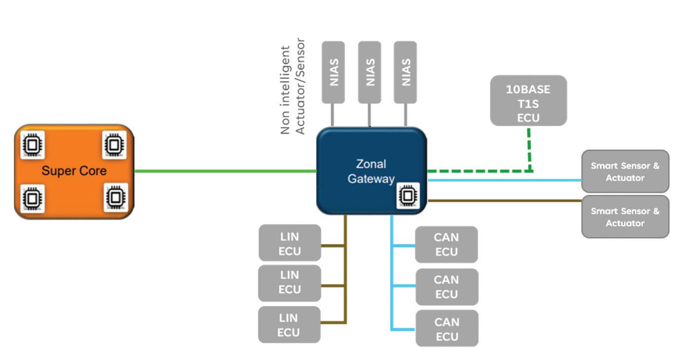
Figure 2. A central core computer (super core) communicates to many zonal gateways inside the vehicle. The gateways then communicate to many actuators or ECUs optimized for vehicle scalability, efficiency, and long-term cost reduction.
and centralized management. Zonal architectures streamline vehicle management by reducing physical components and enabling software-driven upgrades. They even let OEMs consider new business models and take advantage of subscription-based services.
Most significantly, the “clustering” of ECUs reduces wiring complexity, simplifies management, lowers costs, and creates scalable, adaptable vehicle systems.
Advantages of zonal architectures
The benefits of zonal architecture extend beyond cost savings. Reducing the number of ECUs and wiring required makes vehicles lighter and more efficient, a critical advantage for EVs, as weight directly impacts range and performance.
“If you think about cars today, especially with 12-V systems, many cables run throughout the vehicle. These cables add weight and cost, directly impacting efficiency — particularly in EVs, where lighter cars mean longer battery life. Clustering and simplifying the wiring makes creating a more efficient framework possible.”
What’s more: the centralized nature of zonal architecture enables faster data transmission and real-time communication across the vehicle.
“With a zonal control module, OEMs can optimize communication protocols to handle high-speed data transmission while ensuring safety-critical functions are prioritized,” he says.
Another advantage is the ability to decouple hardware and software development. This enables engineers to innovate and iterate faster, creating more
flexible systems that are easier to scale and update.
“When hardware solutions can reuse the same board or protocols, engineers can simply hook the same wires up, reducing hardware demands and enabling faster development,” he adds.
Zonal architecture also addresses the growing need for cybersecurity and firmware upgrades. By centralizing control, over-the-air (OTA) updates can quickly deliver new features or fixes across all modules. Given the volume of data flowing through modern vehicles, protecting systems from interception or tampering is critical.
“If there’s a system update, a central computer can manage deployment to every module in the vehicle, ensuring customers get access to the latest technology without significant downtime,” explains Barrera. “Higher-end microprocessors and central computers are essential, enabling cybersecurity measures like safe rollbacks, encryption, and firmware authentication. Ultimately, the car must recognize the driver from a hacker, safeguarding against unauthorized access.”
3.
The role of 48-volt systems
Zonal architecture also supports the current transition in the automotive industry from traditional 12-volt (V) systems to 48-V ones. The preference for 48-V systems is occurring for several reasons, including power efficiency, weight, and cost savings. Notably, 48-V systems increase power to components without raising the current (Figure 3).
“A 48-V system requires only 25% of the current needed to deliver the same power as a 12-V system, resulting in significant cost and weight savings. Additionally, 48-V systems enable more features and better efficiency, particularly for high-current loads.”
These savings translate into improved vehicle efficiency, as lighter vehicles consume less energy and achieve longer ranges in EVs. Furthermore, lower power dissipation enhances thermal performance, improving reliability and enabling greater system scalability.
While the migration to 48-V systems presents safety challenges, such as higher voltage considerations and increased component costs, advancements in integrated circuits (ICs) and thermal management technologies are providing solutions.
Power distribution is another critical element of zonal vehicle architectures, particularly in managing the coexistence of 48 and 12-V systems. A central component of this process is the Power Distribution Unit (PDU) or Power Distribution Box, which draws voltage from the vehicle battery or an external 48-V supply and converts it for distribution to various zone control modules or gateways.
“There’s a growing need to streamline power distribution across vehicles, especially as we transition to 48-V systems,” Barrera adds. “Efficient power management reduces weight, simplifies wiring, and enhances vehicle performance while supporting high-power applications.”
Power distribution approaches
There are several methods for distributing 48 and 12-V power, each offering unique advantages and drawbacks:
The first approach (Figure 4), 48-V primary distribution with 12-V secondary conversion, involves the PDU sending 48 V to the zone control modules, which then convert it to 12 V for loads requiring lower voltage. This approach provides substantial cost and weight savings
Figure
Today’s electric vehicles contain many 12-V loads in the car, but migration to 48-V loads in the future will enable vehicles to have more features, lower weights, and higher efficiency.
due to thinner, lighter cables for highcurrent 12-V loads while reducing power dissipation. However, the mixed-voltage wire harnesses necessitate stricter safety protocols, and integrating 48-V systems into existing 12-V ECU designs can be highly disruptive.
The second approach, dual 48 and 12-V distribution, sends both voltage levels from the PDU to the zone control modules, allowing greater flexibility to power various loads. This configuration enables direct powering of actuators from the PDU if necessary, offering selective options for either 48 or 12-V loads (Figure 5). However, while this approach provides moderate cost savings, it still requires robust safety measures for mixed-voltage harnesses.
The third approach focuses primarily on 12-V distribution for minimal system disruption while incorporating limited 48-V applications for high-power loads. This strategy requires less redesign for legacy systems, with lower safety demands at the zone control module level (Figure 6). However, it provides fewer opportunities for weight and cost reductions, as the use of 48-V loads is limited.
“Zone control modules play a vital role in managing these mixed-voltage systems,” explains Barrera. “In many 48-V architectures, these modules integrate dcto-dc converters to provide localized 12-V power. They may also consolidate various ECUs and manage a range of loads — including dc motors, stepper motors, resistive loads, and inductive loads.”
Depending on the load requirements, different control topologies — such as high-side drivers, low-side drivers, or H-bridge configurations — are employed to ensure optimal performance and safety.
According to Barrera, manufacturers must consider several key factors to implement mixed-voltage zonal architectures effectively. These include high-current loads (ranging from 10 to 60 amps) and low-current loads (1 to 10 amps), which demand distinct wiring strategies. Of course, safety also remains a top concern, requiring reliable insulation, short-circuit protection and adherence to strict industry standards.
“Transitioning to 48-V systems must balance short-term investment and long-term cost and performance benefits, ensuring scalability for future advancements,” he says. EV
Figure 4. A 48-V primary power distribution with a 12-V secondary power conversion provides high cost and weight savings but higher safety protocols and requires an extensive redesign.
Figure 5. A dual 48/12-V power distribution provides selective flexibility for harnesses and loads with moderate cost savings and safety requirements.
Figure 6. A limited 48-V power distribution has the least amount of redesign for legacy systems but provides fewer opportunities for cost and weight reduction.
What is the automotive open system architecture (AUTOSAR) for EVs?
RAKESH KUMAR PhD CONTRIBUTOR
AUTOSAR (AUTomotive Open System ARchitecture) is a standardized software architecture designed to facilitate the development and integration of software in automotive electronic control units. AUTOSAR plays a vital role in supporting the integration of vehicle-specific features and functionalities.
Why do we need AUTOSAR?
To answer the question, let’s first review how an electric vehicle (EV) network’s components interact in an electronic system. Figure 1 shows the various sensors and actuators connected in an EV.
Each sensor and actuator is connected to a microcontroller and collectively forms an electronic control unit (ECU). The number of ECUs corresponds to an EV’s
sensors and actuators. Additionally, all of the ECUs must communicate with one other for the proper functioning of the vehicle.
The data from one ECU is helpful for the other ECU, which leads to complex electronic machinery inside an EV. Figure 2 illustrates the same principle where several ECUs are networked to each other.
The microcontroller is the core of an ECU, and it can be programmed and reprogrammed to perform various functions. In an institution’s R&D sector, ECUs are trained for a specific application within an EV.
Over the years, a specific ECU becomes a reliable architecture that several OEMs can bank upon. However, this is where it can become a problem.
The matured ECU will possess a proprietary microcontroller from a dedicated manufacturer, which means that the continued success of the ECU also depends on the proprietary microcontroller. This leads to a serious reliability risk in EV manufacturing as any unfavorable conditions — such as price rise or stock unavailability — can also adversely affect EV manufacturing.
When switching to a new microcontroller from a different manufacturer, the ECU must be built from scratch. This is because the new microcontroller will have a different architecture.
Figure 3 shows the underlying problem. The microcontrollers could pose a vendor lock-in problem even though the
Figure 1. The various sensors and actuators in an EV.
EV ENGINEERING
peripherals and software might be open source.
EV OEMs recognized this problem and constituted AUTOSAR in 2003 to develop a common platform for building ECUs. These ECUs were not locked to any particular vendor so that EV manufacturing could grow smoothly.
What are the different architectures in AUTOSAR?
The AUTOSAR architectures are classified into three layers:
• Basic Software (BSW) Layer
• Runtime Environment
• Application Layer
Figure 4 shows the three layers arranged one over the other. The microcontroller is at the base of these layers below the BSW Layer.
The BSW Layer has different functions as set by AUTOSAR. Its primary function is to perform as an operating system for the ECU. In addition, BSW communicates via established protocols such as CAN, LIN, or ethernet. It also has access to all input and output ports and handles system diagnostics.
The BSW layer has four inner layers: the Microcontroller Abstraction Layer, the ECU Abstraction Layer, the Service Layer, and the Complex Drives Layer. Let’s review each one.
Microcontroller Abstraction Layer
Popularly called MCAL, this layer is directly connected to the microcontrollers
and forms the bottom layer of BSW. Its task is to make the higher software layers work independently of the type of microcontroller used.
The MCAL functions as an API between the microcontroller and the rest of the top layers. It’s more relevant to the semiconductor manufacturing industry because the microcontroller at the bottom
Figure 2. Components in an ECU and their arrangement.
Figure 3. The components for building an EV body control unit.
can be configured using information from MCAL.
This layer combines the controller drivers, memory drivers, crypto drivers, wireless communication drivers, communication drivers, and I/O drivers.
ECU Abstraction Layer
The ECU Abstraction Layer allows access to the software in the other ECU’s Application Layer. This means that a particular software is not bound to a specific ECU and that not all the software needs to be present in the Application Layer of each ECU.
The higher layers can easily access the drivers present in the MCAL via the ECU Abstraction Layer. This layer hosts the various drivers meant for external devices. It is good to know that this layer keeps the higher layers independent of the ECU hardware layout.
The functions of the ECU Abstraction Layer are:
• Onboard device abstraction
• Memory hardware abstraction
• Crypto hardware abstraction
• Wireless communication hardware abstraction
• Communication hardware abstraction
• I/O hardware abstraction
Complex Drivers Layer
Not a native layer of the original AUTOSAR architecture, the Complex Drivers Layer is meant for functionalities that are outside the purview of the other BSW layers.
The fact that this layer has a direct connection between the microcontroller and the Runtime Environment Layer shows that it can bypass the BSW Layer if necessary.
Service Layer
The Service Layer is the highest of the BSW Layer and houses the operating system of the ECU. It performs various non-volatile memory services and diagnostic services.
The Service Layer governs the various states and mode management of the ECU. This layer provides the communication service to network the different contact points within the vehicle. The Service Layer takes care of the system services, memory services, crypto services, off-board communication services, and communication services. Run Time Environment
The Run Time Environment (RTE) layer connects the Application and BSW Layers as a data and signal exchange medium. It also plays a similar role by connecting the different software components within the Application Layer of a specific ECU without passing through the ECU Abstraction Layer.
However, when the software components in the Application Layer of other ECUs are to be contacted, the RTE layer will ping the BSW layer and use the ECU Abstraction Layer.
One of the key advantages of the RTE layer is its ability to offer flexibility in programming the ECUs, thereby preventing any one-time program locking and empowering the developers.
Figure 4. The different layers in the AUTOSAR architecture.
Figure 6. The Run Time Environment layer in the AUTOSAR architecture.
Figure 5. The BSW Layer in the AUTOSAR architecture.
Figure 7. The Application Layer in the AUTOSAR architecture.
Application Layer
Application Layer is the layer for which many OEMs pay and buy the ECU itself. This layer houses the different software components and can change from one ECU to another.
This layer often specializes in a specific application, such as a door lock or airbag mechanism. Heavy research is focused on making this layer robust, and it is fast developing into a lucrative career in EV engineering.
Even though this layer calls for software specialization, another ECU can also use the software component of an Application Layer. For this matter, the communication has to pass to the ECU Abstraction Layer of all the ECUs concerned.
Summary
AUTOSAR is not just a standard protocol but an exciting career opportunity for those aspiring to become EV engineers. This protocol is meant to break any vendor lock-in mechanism, which means that the scope of AUTOSAR spans a wide variety of EV markets. EV
Coilcraft’s MSS1514V high-voltage power inductors are rated at 800 V, doubling the voltage capacity of comparable parts.
Note: All images courtesy of Rakesh Kumar, Ph.D.
By Eugene Demaitre and Mike Oitzman • The Robot Report
Universal Robots discusses for collaborative automation
Both the enabling technologies and use cases for collaborative robot arms are continuing to evolve, according to Chris Savoia, head of ecosystem success for the Americas at Universal Robots A/S. He recently spoke with The Robot Report Podcast about this and topics including the importance of safety, recent advances in higher-payload robots, and mobile manipulators.
Savoia also discussed Odense, Denmark-based Universal Robots’ new Polyscope X platform for developers, the enhancements from MotionPlus, and the OptiMove control feature.
Here are some highlights of that conversation, edited for length.
UR+ ecosystem, payload capacity both grow Mike Oitzman: We've watched the success of the UR+ ecosystem. It
speaks to the utility of the UR robot and how you've been able to go to so many different segments and verticals in the marketplace to hit with specific applications and using other partners to get you there.
Savoia: You'll see a recurring theme with us that we're a platform company. And we're still on the precipice of unlocking robotics for the masses.
I think a big part of that is giving people a platform to do innovation. You know, we couldn't have seen all the things that were going to happen with the ecosystem when we first set out to do it.
And it's been really cool to see the way that our partners pull us into places that we don't want to go or don't [initially] think are important.
Eugene Demaitre: Speaking of robotics trends and innovation, Universal Robots has released newer, higher-payload cobots. Collaborative robots were always viewed as sort of a subset or even a cousin to industrial robots, but that's no longer really the case, is it?
Savoia: In the past year and a half, Universal Robots has released the UR 20 and the UR 30, which are 20 kg [44 lb.] and 30 kg [66 lb.], respectively.
I like to think of it as still human scale. They have allowed us to build out a portfolio that allows the breadth of what a human might do.
We're not going to be picking up electric vehicles, battery packs, and things like that. We're not going to have 2,000 kg [4,409 lb.] payload robots, but certainly we’re approaching industrial scale.
The MC600 combines a UR cobot arm with a MiR base. Mobile Industrial Robots
In the past quarter or so, we also took the UR20 and UR30 and added five more kilograms of payload. That was done in a very specific way. So that's only done when the tool flange or the end of the robot is pointed down. And so you can imagine that it's only in the orientation where you'd be picking up a box or something like that.
The natural thing to question there is, how can you just give a robot five more kilograms? There are obviously mechanical things going on, but it’s important to point out that robots are not just mechanical systems. They're very tightly integrated with software control systems.
In fact, UR cobots are not weak robots. They just have a very good control system and a safety system that's governing the amount of torque and power that the motors and joints can put out. So what we've been able to do is find in that particular orientation, there's mechanical surplus that allows us to get this extra payload.
Get started with safety assessments
Demaitre: In terms of safety, we always tell people they need to do a safety or risk assessment based on the application and not just on the robot because the
payload, the range of motion, all those things matter.
Savoia: I'm really active in the safety community. I go to the [ANSI/RIA] R1506 meetings all the time, and I'm very up to date with like what's happening with these changes in ISO 10218 and things like that.
People may think that a safety assessment is a big bearish thing to think about. If I had one piece of advice is that it is way easier than you think it is. It really is about just looking at who is in the workcell, what those people are doing, the tasks in the workcell, and then how much of a chance do you have of those tasks of hurting someone.
And there's tons of really good documentation, like Robotiq’s riskassessment flow chart. The hardest thing is starting; it’s like writing an essay for school. You just gotta do it, and then it gets way easier.
PolyScape X is part of UR’s platform strategy
Demaitre: Can you tell us a bit about what the PolyScope X release means, and how does it help robotics developers and end users?
Savoia: This is a big re-platforming for us. It's a really important piece of our strategy going into the future.
PolyScope X allows us to do a lot of things that we have found through a lot of repetition to be difficult in the past. We've had this amazing ecosystem of people developing apps, and we're taking that to the next level now. PolyScope X is as much for developers as it is for end users.
For developers, we're giving you access to modern technologies and modern web stacks that a lot more developers are going to be familiar with. So if you can program in React or Angular or JavaScript at all, you can program a URCap.
We've already seen a ton of testimonials of people coming in and being like, “I've literally never touched a robot in my life. I have no idea about them, but I was able to bust out this
PolyScope X is designed to make robot application setup easier. Universal Robots
The UR30 cobot can lift up to 35 kg in certain orientations. Universal Robots
awesome piece of software for your robot that enables it to do something so cool.”
If you’re using the teach pendant, you can call up YouTube videos and load up a chat with someone from our partner Hirebotics. You can do all the cool things that were on its phone app before but now do them right in the robot.
That makes the entire development experience way better because it can share those same frameworks across everything there. There's also stuff around cybersecurity and other things.
MotionPlus and OptiMove add control
Demaitre: Another UR enhancement is MotionPlus – what does that support?
Savoia: So MotionPlus is a platform or an API [application programming interface] that we offer now. It's free if you want to use a single additional axis, so you can just download a URCap from us, but there's a cost to it if you want to control multiple accesses around the workcell.
If you look at robotic arms, a lot of times, if there’s six axes, they’ll be able to support a seventh or an eighth axis. So the robot can slide around on a rail or maybe turn a rotary stock unit when it's welding.
In almost every case, they support only the servo drives of that manufacturer. What we've done with MotionPlus is allow control through EtherCAT of many different servo brands on a very low level in a repeatable way.
You can also see how it would work with palletizing, where you can now actuate a seventh axis at the same time as the robotic arm. MotionPlus allows us to talk to other servos and to coordinate motion with any third party.
Demaitre: And what does OptiMove mean for controller optimization?
Savoia: OptiMove is one of those like sleeper features that like, unless you're picking up a teach pendant, you probably won't care about or know about. OptiMove strips away all of that tribal knowledge that comes with understanding speeds and accelerations.
And sometimes speeds and accelerations with robots are in angular
speeds and accelerations, which really are not intuitive to understand. I mean, what is 500 mm [19.6 in.] a second squared acceleration?
All those amazing UR engineers in Denmark have created a slider from 0 to 100. How fast do want to go with OptiMove? It's just going to optimize everything, taking into account payload, orientation of the robot, the safety settings, and everything like that.
Universal’s robots have an understanding of where their safety system is, what their payload is, and it'll actually govern your accelerations and speeds so that you don't trip the robot with nuisance stops. Not only does it make our robots last longer, but it also makes them a bit easier to use.
The net benefit is we've been able to do things like jerk limiting and all these derivations, like drive speed into acceleration. What that means is that the robot can pick up a heavy box easier, as the transition from zero payload to a heavy payload gets smoother. It gets more accurate and settles faster. RR
OF ECOSYSTEM SUCCESS FOR THE AMERICAS UNIVERSAL ROBOTS A/S
For the full conversation, tune in to the podcast episode.
WTWH.ME/ URECOSYSTEM
The UR+ ecosystem and features such as OptiMove are expanding use cases for collaborative robots. Universal Robots
CHRIS SAVOIA HEAD
While advances in humanoid robots have attracted public and investor attention over the past few years, mobile manipulation could be helping businesses sooner rather than later. Engineers have long experimented with combining collaborative robot arms with mobile platforms. In the past few months, commercial offerings have started to come to market.
The combination of lighter cobots with autonomous mobile robots (AMRs) promises greater flexibility for applications such as machine tending, piece picking, quality inspection, and surface finishing. But first, developers need to ensure that mobile manipulators have integrated controls, power management, and perception for safety.
Here are recent announcements around cobots and mobile manipulation:
Kassow offers compact Edge Edition
In November 2024, Kassow Robots introduced its Edge Edition cobots, which are specifically designed to work with automated guided vehicles (AGVs) and AMRs.
The new cobots feature a direct DC connection from battery power, enabling them to operate while mounted to a mobile robot. They offer remote power on/off control, allowing for control from the mobile robot controllers or a PLC, said Kassow.
The Teradyne Inc. unit added that its cobots can run in automatic mode without a teach pendant, streamlining operations.
The robots have a standard footprint of 160 x 200 mm (6.2 x 7.9 in.) ensuring compatibility with various applications.
Kassow’s cobots are also equipped with sensors that detect overload, ensuring safe operation in shared workspaces. The company said this eliminates the need for special safety measures, expanding the range of applications to include repetitive, dangerous, and dirty tasks.
However, a thorough risk assessment must be conducted before deploying such robots in any environment. It should include both parts of the mobile manipulator, as well as any workpieces.
“At the end of the day, we want to make it easier for our customers to integrate cobots into mobile solutions,”
said Kristian Kassow, co-founder of Universal Robots and founder of Kassow Robots.
“A look at today’s AGVs and AMRs quickly reveals just how little space they offer. Robot controllers are mostly bulky, making it harder to automate tasks,” he told Collaborative Robotics Trends. “Our Edge Edition cobots feature a slim base. We help system integrators and end customers simplify the implementation of these AGV/AMR and cobot solutions.”
Collaborative Robotics unveils Proxie mobile manipulator
After two years of relative secrecy, Collaborative Robotics Inc., or “Cobot,” unveiled its Proxie robot late last year. Company founder Brad Porter has suggested that the kinematics of a mobile manipulator are better suited to warehouse workflows than those of humanoid robots.
At Amazon, Porter led the deployment of more than 500,000 robots as vice president of robotics and distinguished engineer. After Amazon, he said saw an opportunity to accelerate more ubiquitous autonomy through better data and tooling, leading him to join Scale AI as chief technology officer.
In April 2024, Santa Clara, Calif.-based Collaborative Robotics closed a $100 million Series A round to commercialize its technology. Porter told Collaborative Robotics Trends that Proxie is already in trials with several pilot customers, including a global logistics company.
Proxie’s mobile base is different than other AMR bases, noted Porter.
“The swerve drive gives you pseudo holonomic motion, enabling you to slide sideways into a set of shelving units. The swerve drive also enables you to snap the casters before you start to move,” he explained. “With a differential drive base, the AMR doesn’t have the degrees of freedom, so it’s more clumsy. Finally, mecanum wheels have other problems that are difficult to manage in production.”
On top of the base is a vertical linear axis that carries a dual-arm, cart-interfacing gripper for cart-moving implementations. A six-degree-offreedom (DoF) cobot arm will be an optional configuration for Proxie in the future.
Porter added that Seattle-based Cobot has a dual-arm manipulator in its lab, equipped with ALOHA grippers for manipulation tasks.
MC600 combines UR arm with heavy MiR base
Also in November, Mobile Industrial Robots ApS (MiR) announced the latest addition to its list of MiR Go-approved products, the MC600 mobile collaborative robot. It combines the MiR600 AMR with the UR20 and UR30 cobots from Universal Robots A/S (UR), which is also owned by Teradyne.
Ever since Teradyne acquired UR, MiR, and Kassow, the editors of Collaborative Robotics Trends have asked the
company when it would combine their technologies.
“While some companies have explored humanoid robots or one-off custom mobile cobot solutions for such tasks, they remain far from widespread industrial use,” stated Jean-Pierre Hathout, president of Mobile Industrial Robots. “The MC600 is ready today to safely handle these complex automation challenges.”
A unified software platform by MiR Go partner Enabled Robotics coordinates the mobile base and robotic arms. Mobile Industrial Robots said this simplifies integration into existing workflows and ensures smooth operations.
The MC600 can handle payloads up to 600 kg (1,322 lb.) and automate complex workflows in industrial environments, said Mobile Industrial Robots.
“The smaller MC250 has proven especially popular in semiconductor fabrication facilities and other lowerpayload manufacturing tasks, but there’s been a clear demand for a mobile cobot that could handle heavier manufacturing applications,” noted Ujjwal Kumar, group president of Teradyne Robotics.
Building on the success of the smaller MC250, the MC600 can handle heavier items to automate tasks such as palletizing, box handling, and machine tending, said MiR. The UR20’s extended reach allows the new robot to tackle tasks that were previously inaccessible to smaller cobots, it claimed.
The Edge Edition cobot lineup is designed to be compact.
Kassow Robots
The global market for mobile cobots is projected to grow 46% annually by 2030, said Odense, Denmarkbased MiR.
ASTM proposes mobile manipulation standard
With cobots being paired with mobile robots comes the need for applicable industrial standards. ASTM International’s F45 committee for robotics, automation, and autonomous systems has proposed a new standard, WK92144.
It would provide guidelines for documenting disturbances of robot arms in unstructured manufacturing environments. The proposed standard also describes an example apparatus for testing.
According to ASTM member Omar Aboul-Enein from ASTM, factors such as heavy machinery can affect these robots, especially in critical sectors like aerospace and energy that deal with complex parts.
“Many applications of mobile manipulators require high degree of position and orientation accuracy and repeatability,” he said.
ASTM International welcomes manufacturers, integrators, and end users to participate in its standards efforts. Contact the organization at its website: www.astm.org/JOIN. RR
Editor’s note: Mike Oitzman contributed to this article.
ROBOTICS
New England Wire Technologies
Advancing innovation for over 100 years
Why accept a standard product for your custom application?
NEWT is committed to being the premier manufacturer of choice for customers requiring specialty wire, cable and extruded tubing to meet existing and emerging worldwide markets. Our custom products and solutions are not only engineered to the exacting specifications of our customers, but designed to perform under the harsh conditions of today’s advanced manufacturing processes. Cables we specialize in are LITZ, multi-conductor cables, hybrid configurations, coaxial, twin axial, miniature and micro-miniature coaxial cables, ultra flexible, high flex life, low/high temperature cables, braids, and a variety of proprietary cable designs. Contact us today and let us help you dream beyond today’s technology and achieve the impossible.
The MC600 is designed to automate the movement of heavier items. Mobile Industrial Robots
IEC 60320 rewirable sheet E plug connector
Interpower • interpower.com
Interpower announces the launch of its newly manufactured IEC 60320 rewirable Sheet E plug connector in a straight cable mount configuration initially offered in black. The Sheet E plug connector recently obtained Japanese PSE approval, joining other Interpower Sheet E plug connector safety agency approvals such as cULus, VDE, and CCC.
The Interpower part number for the new Sheet E is 83032000, replacing part 83011060. Sheet E compatible wire sizes in North America are 18, 16, and 14 AWG (SV/SJ types); in Europe and China, 0.75 mm² and 1.0 mm² (H05VV-F/RVV EU); also in Europe, 0.75 mm² and 1.0 mm² (H05RN-F EU); and in Japan 1.25 mm² (VCTF). The rewirable Sheet E plug connector carries a UL 94 V-0 flammability rating.
The connector plug material is Polybutylene terephthalate (PBT) with nickel-plated brass terminals and is rated 10A (international) and 15A (North American) 250VAC. Loss of electrical continuity could occur to any plug in the industry if improperly disconnected at severe angles over time. One advantage of a rewirable plug is having access to “rewire” the conductors, which can be inspected or repaired by simply removing the four screws from the PBT housing.
AutomationDirect has added configurable and programmable safety relays from Schmersal. Many safety systems require more than one specialty safety relay but do not justify the need for a safety controller. Schmersal PROTECT SRB-E configurable relays are easy to set up and reduce the number of safety relays required for a machine or system. These relays include up to 10 safety inputs and up to 5 safety outputs, support up to 16 different applications, and can monitor all conventional safety devices.
Schmersal PROTECT SELECT programmable relays can replace up to 8 safety relays, have a simple multilingual menu on a color display, and report error and status messages. Programmable relays require no prior programming experience and offer up to 4 pre-configured safety monitoring programs to choose from.
INA stainless-steel radial insert ball bearings CT Series toggle switch
Schaeffler • schaeffler.us
Global motion technology company Schaeffler has unveiled its new lineup of INA Stainless-Steel Radial Insert Ball Bearings. Available with housings made from rugged stainless steel (shown here) or lightweight thermoplastic, these bearings are engineered to meet the demands for corrosion resistance, reliability, and stringent hygiene standards required by the food & beverage sector.
Schaeffler's stainless-steel housings for radial insert ball bearings are a good choice for environments where strength and resilience are paramount. Designed to offer greater tensile strength, these housings are especially resistant to deformation and cracks. Their construction ensures that they do not absorb moisture, even after frequent washdowns, making them suitable for the rigorous cleaning cycles typical in the food & beverage industry. Available in both metric and inch sizes, Schaeffler’s stainless-steel housings are also lubricated for life, ensuring minimal maintenance and maximum operational uptime.
APEM • apem.com
Offered in familiar form factors with innovative options, these CT Series toggle switches and accessories integrate thoughtful design details. They provide improved performance and incorporate the features needed for industrial-grade applications in agriculture, material handling, heavy equipment, and specialty vehicles.
The APEM CT Series toggle switches are offered in various form factors and configurations, with a wide selection of associated accessories such as nameplates, protective boots, and switch guards. The most common and popular part numbers are ready for rapid order fulfillment.
One- and two-pole versions, rated 15A @ 28V DC and 10A @ 125/250V AC, with screw, solder lug, or quick connect terminals, cover an extensive range of specified applications. With UL approval, an IP67 waterproof rating, and a wide operating temperature range of -45 to +85 ° C, the CT Series is well-suited for use in the harshest environments.
Ryan Ashdown rashdown@wtwhmedia.com 216.316.6691
Jami Brownlee jbrownlee@wtwhmedia.com 224.760.1055
Mary Ann Cooke mcooke@wtwhmedia.com 781.710.4659
Jim Dempsey jdempsey@wtwhmedia.com 216.387.1916
Mike Francesconi mfrancesconi@wtwhmedia.com 630.488.9029
Jim Powers jpowers@wtwhmedia.com 312.925.7793
Publisher Courtney Nagle cseel@wtwhmedia.com 440.523.1685
CEO
Scott McCafferty smccafferty@wtwhmedia.com 310.279.3844
DESIGN WORLD does not pass judgment on subjects of controversy nor enter into dispute with or between any individuals or organizations. DESIGN WORLD an independent forum for the expression of opinions relevant to industry issues. Letters to the editor and by-lined articles express the views of the author and not necessarily of the publisher or the publication. Every effort is made to provide accurate information; however, publisher assumes no responsibility for accuracy of submitted advertising and editorial information. Non-commissioned articles and news releases cannot be acknowledged. Unsolicited materials cannot be returned nor will this organization assume responsibility for their care.
Subscription Rates: Free and controlled circulation to qualified subscribers. Nonqualified persons may subscribe at the following rates: U.S. and possessions: 1 year: $125; 2 years: $200; 3 years: $275; Canadian and foreign, 1 year: $195; only US funds are accepted. Single copies $15 each. Subscriptions are prepaid, and check or money orders only.
Subscriber Services: To order a subscription or change an address visit our website at: www.designworldonline.com
DESIGN WORLD (ISSN 1941-7217) is published monthly by: WTWH Media, LLC; 1111 Superior Ave., Suite 2600, Cleveland, OH 44114. Periodicals postage paid at Cleveland, OH & additional mailing offices.
POSTMASTER: Send address
By Mark Jones
Don’t trash those plastic spatulas
2024 was the year of spatulageddon. Plastic spatulas were trashed due to reports of dangers lurking within. The journal article that raised concern contained an error, an obvious error. A correction was made, but there’s more to the story.
The study causing spatulageddon was published in the journal Chemosphere. The corresponding author is affiliated with Toxic-Free Future.
The study found brominated flame retardants where they shouldn’t be, in objects used to touch food. A now banned compound, BDE-209, was deemed particularly worrisome. “Estimation of exposure to BDE-209 from contaminated kitchen utensils indicated users would have a median intake of 34,700 ng/day, exceeding estimates for intake from dust and diet” according to the authors. They went on to conclude, “Products found in this study to contain hazardous flame retardants included items with high exposure potential, including foodcontact items as well as toys.” Pretty alarming stuff. A PR push by Toxic-Free Future resulted in headlines like “Black Plastic Kitchen Tools Might Expose You to Toxic Chemicals. Here’s What to Use Instead” from the New York Times and “Throw Out Your Black Plastic Spatula” from The Atlantic. Spatulageddon was on.
Early in 2024, the Freakonomics podcast introduced me to the
concept of convenient errors. Leif Nelson of Data Colada explained that a one decimal point error, potentially a typo, may well escape notice if it is the direction supporting the hypothesis. That is exactly the type of error made here. Authors missed an easily detectable factor of 10 error. Reviewers missed it. Editors missed it. Once stories started to appear, sharp-eyed readers found it.
Digging into the error left me disheartened. To determine whether BDE-209 presented an acceptable or unacceptable risk, the EPA reference dose of 7,000 ng/kg of body was used. A reference dose is the maximum amount that will not cause harm. 7,000 ng/kg body weight per day for a typical 60-kg adult is 420,000 ng/day. A convenient error was made. 42,000 ng/ day was mistakenly used. Instead of concluding levels below the reference dose were okay, 80% was reported as too close for comfort and a reason for concern. Once corrected, the exposure estimate drops to a more comfortable 8%.
The estimated exposures are well below the corrected reference dose. The correction attached to the article does not back away from the conclusion that recycled plastic in food contact applications is an unreasonable risk. Others have questioned how the conclusions remain valid.
I am doubtful the paper would have been noticed with the correct reference dose. A headline claiming levels claiming spatulas are okay wouldn’t garner much attention. The convenient error got the work noticed.
But there is even more reason to doubt the conclusions. 203 items were collected and screened. Only 20 testing above 50 ppm bromine were analyzed for flame retardants. 183 items
didn’t have concerning levels. The ambiguously worded abstract states that flame retardants were found in 85% of the samples when, in reality, they were detected in only 17 of 203 samples, only about 8%. The ratio is similar for kitchen items. Only 9 of 109 measured high enough for additional testing. Over 90% were okay.
Previous work by other researchers formed the basis for exposure estimates based on exposure to hot oil. That work concluded handling of objects was unlikely to cause exposure. A relationship connecting BDE-209 concentration to exposure upon heating in oil was developed and the 20 samples tested included food service ware, toys, kitchen utensils, and hair accessories. Only a subset of kitchen utensils are used with hot oil. Utensils like peelers never contact hot oil. 34,700 ng/day is calculated using the average of all 20 of the BDE-209 measurements, including the hair accessories, toys, and peelers. The highest measured spatula gives an exposure estimate less than 0.4% of the EPA reference dose. Spatulageddon should never have happened.
A couple of things are clear. Most concerning is this story illuminates failures of peer-review. Convenient errors slip through even when obvious. More subtle errors are surely being missed. Once ominous sounding science hits the press, getting it corrected in public opinion is unlikely. Recycling does create risks that aren’t present with virgin material. We have to trust actors in the recycle chain are keeping those risks tolerable. This study shows we are recycling with tolerable risks. Lastly, if you didn’t throw out your black spatula ... don’t. DW
Redi-Rail ®
Practical Precision in Linear Motion
Precision aluminum rails with hardened steel races ensure a lightweight design without sacrificing strength. Gothic arch rollers with sealed double-row ball bearings provide high load capacity and reliable operation in contaminated environments. The carriages come standard with 3-rollers or can be upgraded to a 4-roller or 5-roller carriage. Patented preload adjustment allows for adjustments without the need for disassembly.
Hevi-Rail ®
The Apex Weightlifter in Linear Motion
Built for extreme high-load capacities and industrial strength handling, the Hevi-Rail system is easy to mount, align and use. High radial and axial load capacities ensure a long and productive life under continuous use. Available in a range of sizes from the smallest 52.5 mm diameter HVB-053 bearing to the largest 149 mm diameter HVB-063 bearing making the Hevi-Rail a perfect solution for heavy load and lift applications.