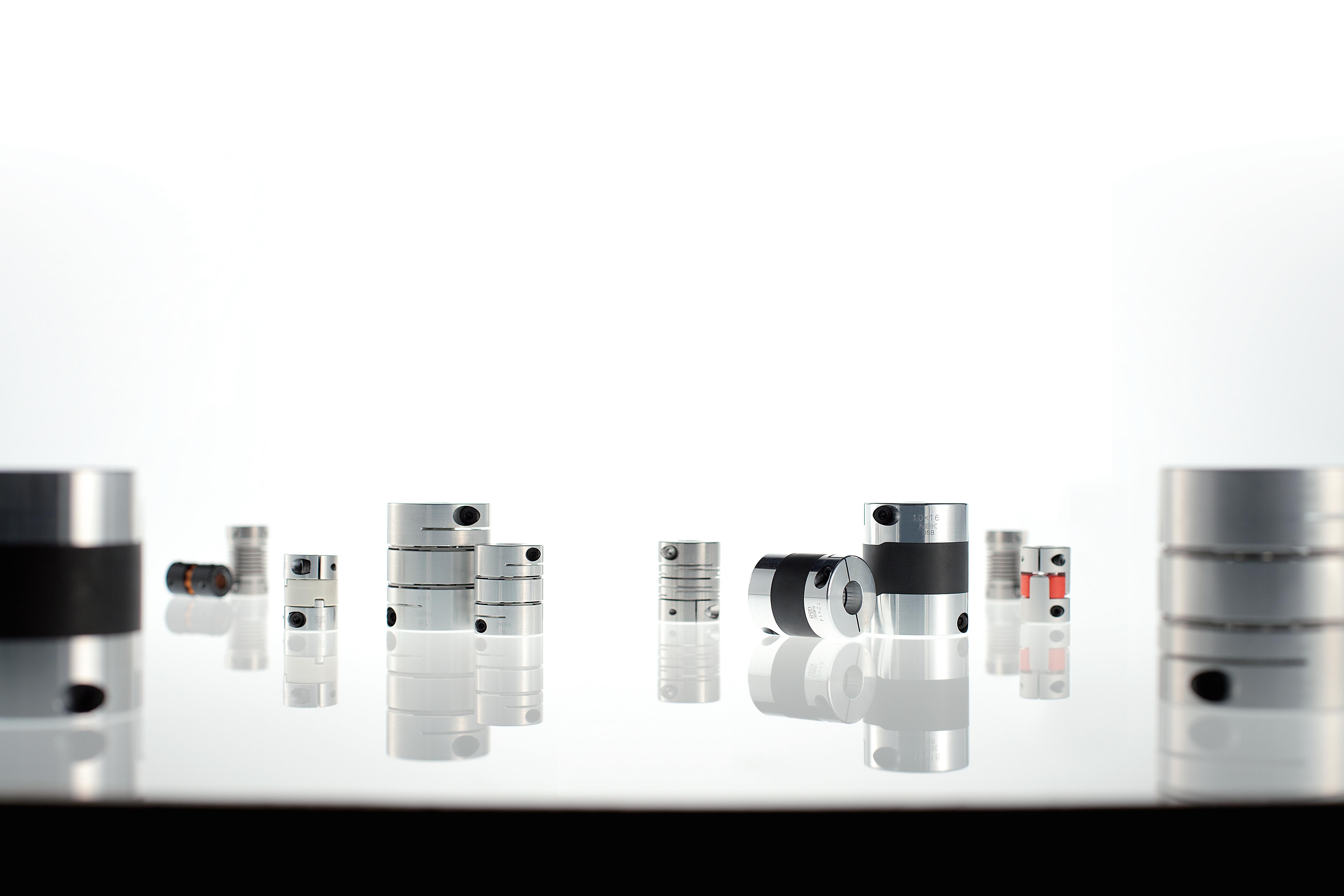
motion control handbook


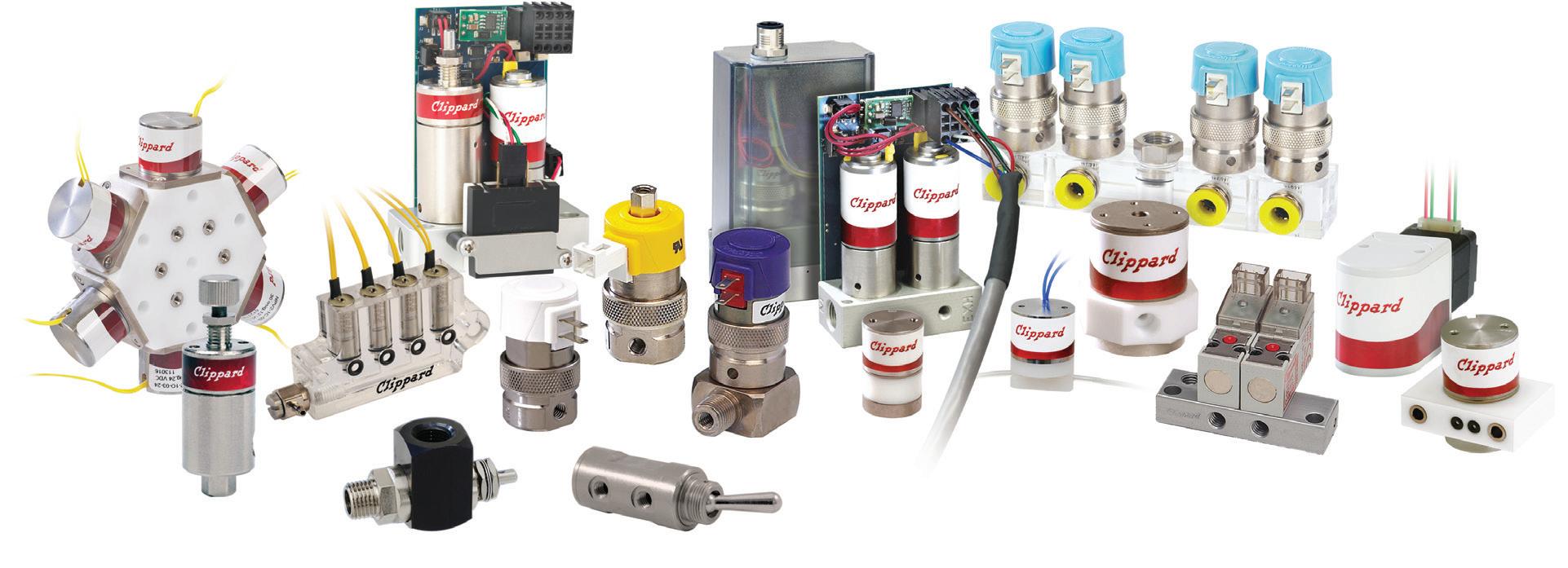
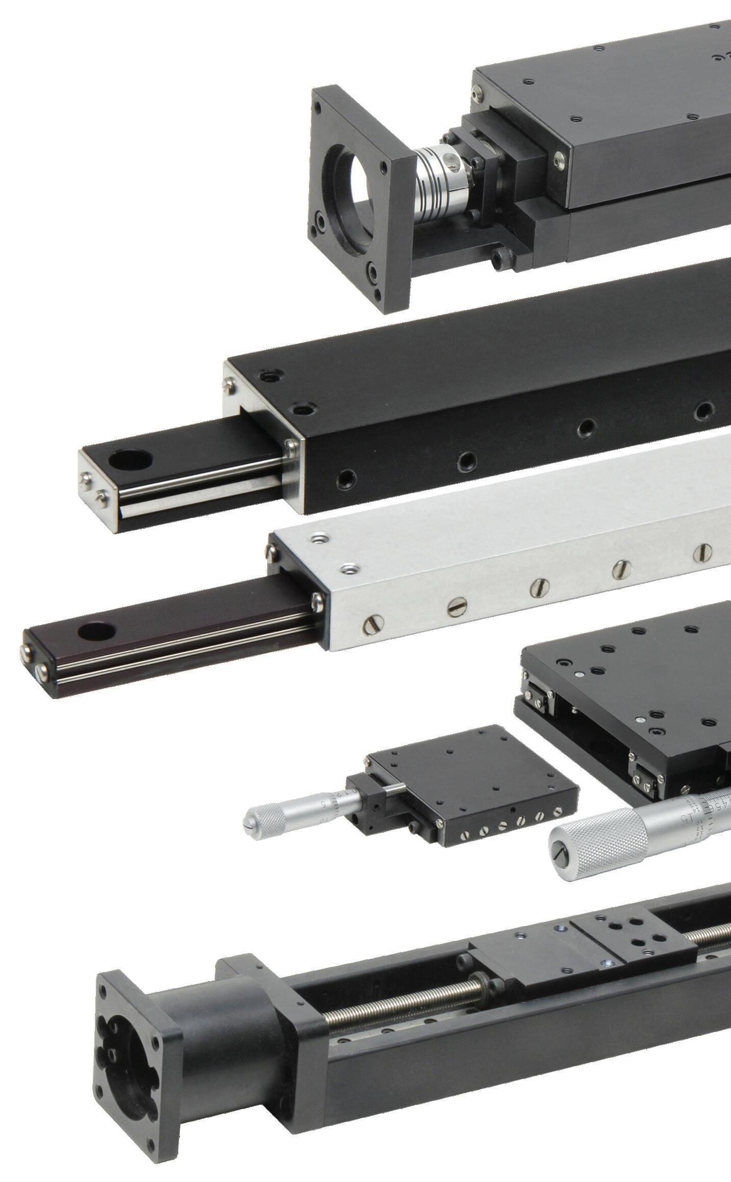
THK is a leading manufacturer of high quality and ultra precise miniature linear guides, ball screws, cross roller rings and actuators for a wide range of industries, including industrial automation, medical, aerospace, semiconductor, machine tool and robotics.


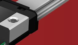


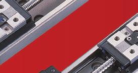
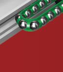
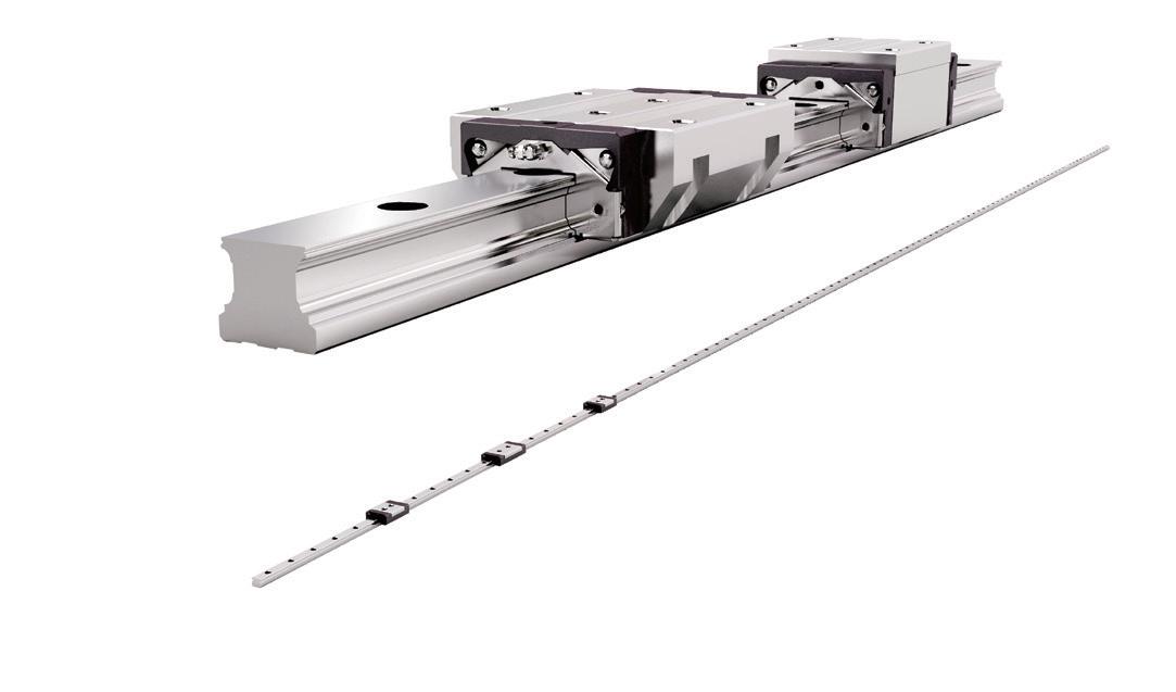
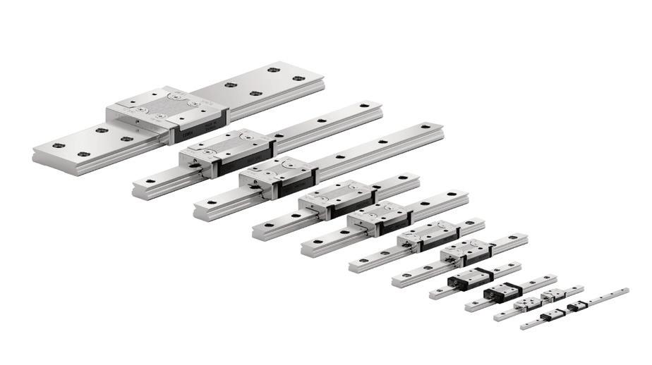
LM Guides - SRS Series - Featuring patented THK Caged Technology, the SRS Miniature LM guides perform with smooth and quiet motion, long-term maintenance free operation, increased speed and accuracy, low dust generation and a long life.
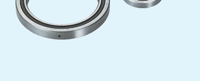
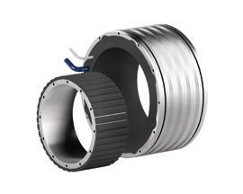
Cross Roller Rings - RAU Series - THK Micro Cross Roller Ring Series RAU are compact and lightweight and even more rigid than a double row angular contact ball bearing type. Spacer retainers enable smooth movement and high rotation accuracy.
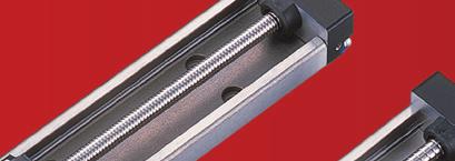
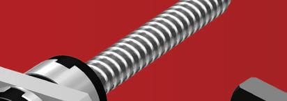
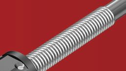
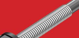
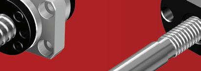
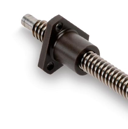
Ball Screws - BNK and MTF Series - BNK with finished shaft ends and MTF Roll-Formed screw shaft are known for their high accuracy, low noise, smooth movement and long-term maintenance free operation.
Actuators - KR Series - KR Actuators consist of LM guide units on the ends and ball screw unit in the center making them highly rigid and highly accurate in a minimal space.
To learn more, call us at 847-310-1111 or visit www.thk.com.


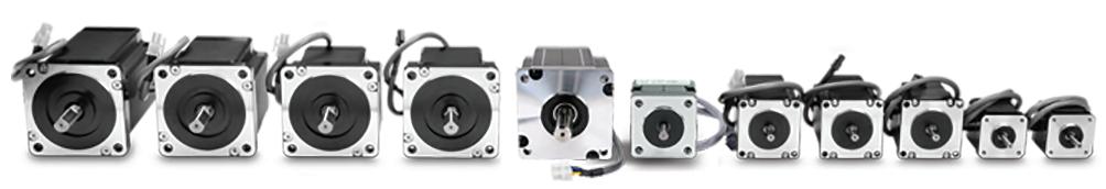
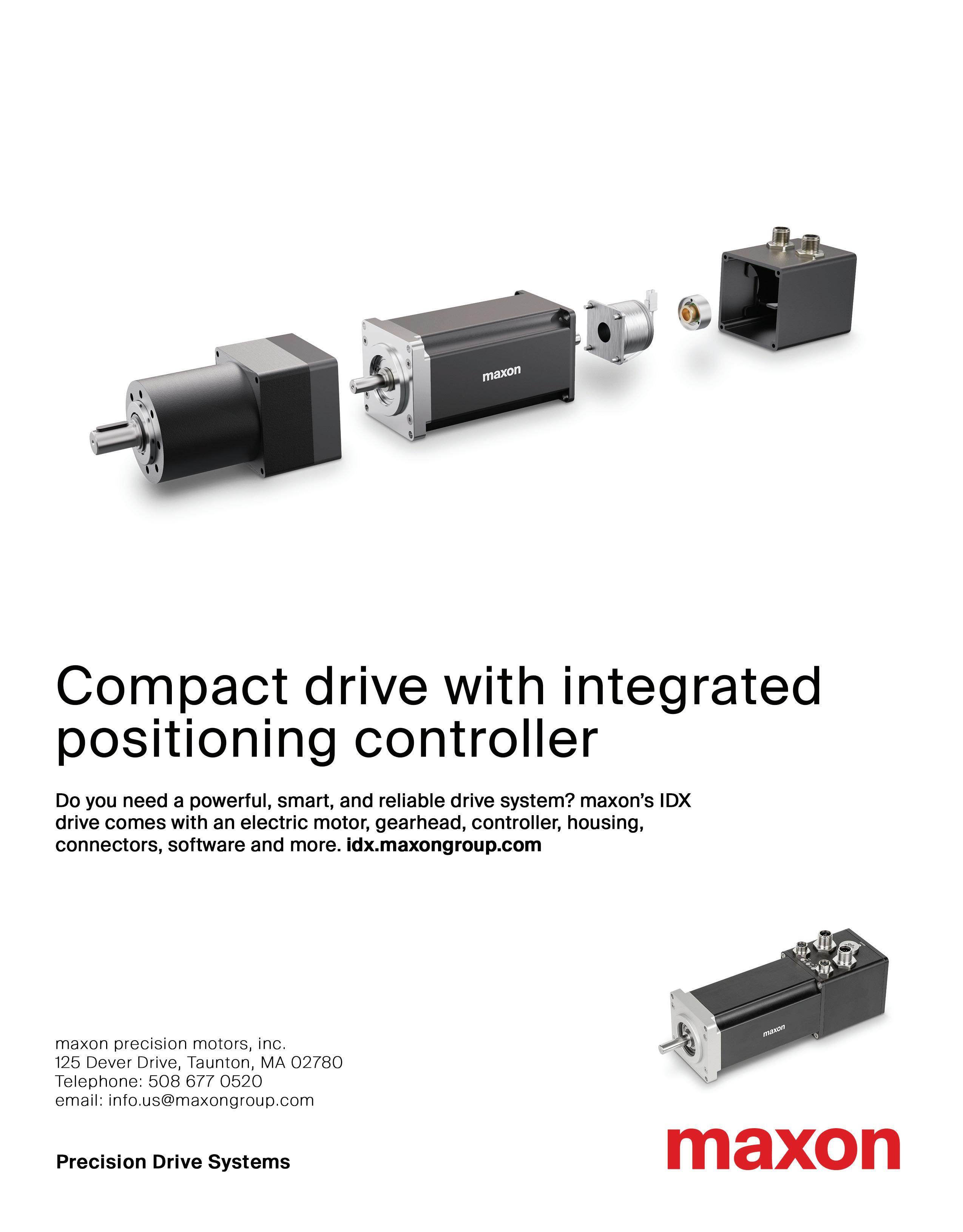
Stepper Motors, Drives, and Linear Actuators
Motors starting at: $22.50 (STP-MTR-17040)
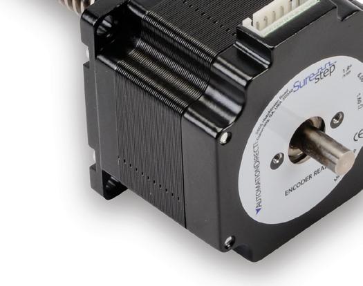
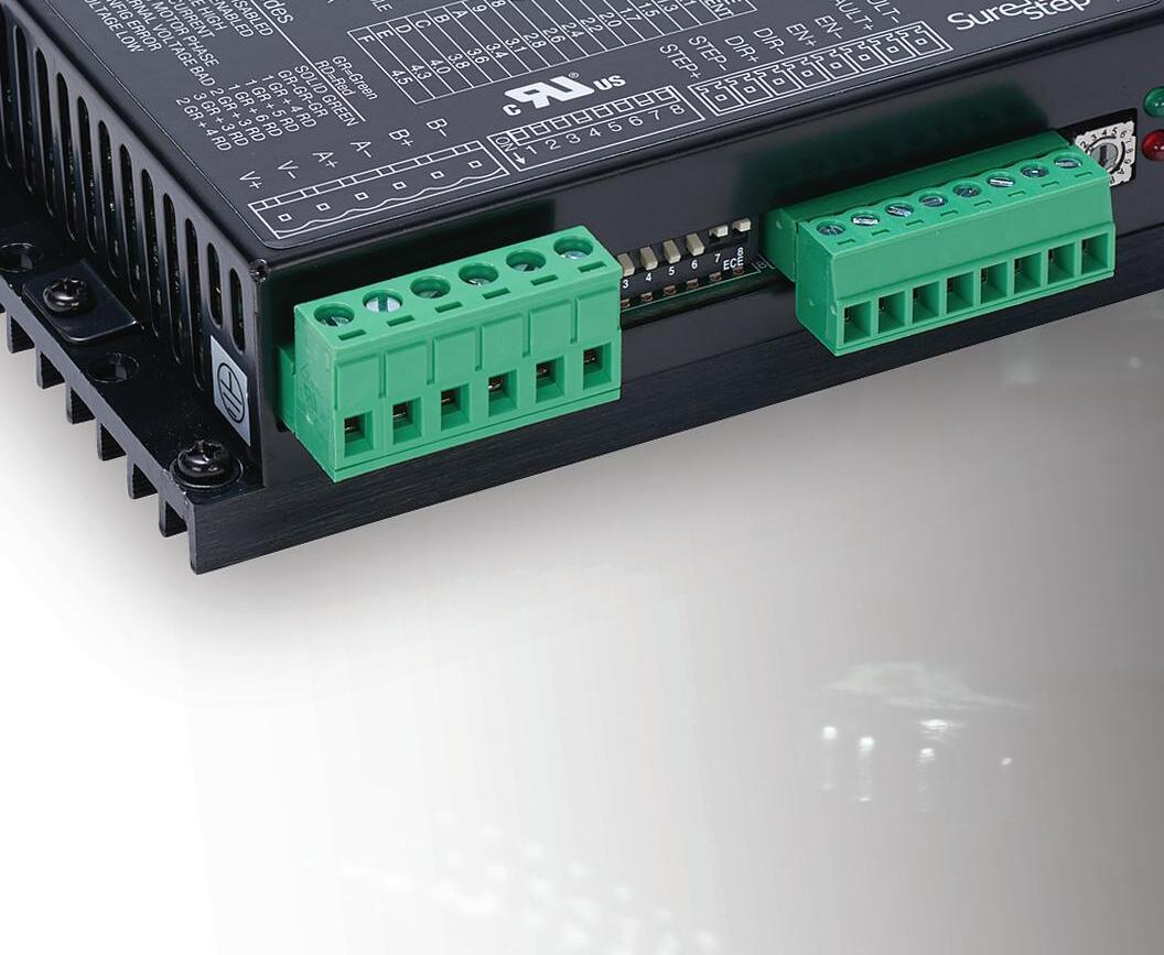
SureStep stepping systems marry high-performance microstepping drives with high-torque stepper motors (in single- and dual-shaft models) to provide simple and accurate control of position and velocity.
For utmost space and cost savings, integrated stepper motors and drives combine high-performance microstepping drives with high-torque stepper motors in one single unit. Standard and advanced models are available.


Use our Stepper System Selector to size a stepper motor for your application, then walk through all the options for that motor; including encoders, drives, power supplies, cables, and more.

www.automationdirect.com/selectors/steppers
Stepper motor linear actuators consist of a stepper motor with a lead screw as the rotor. These actuators translate the precise rotational movement of the stepper into a linear motion. Stepper motor linear actuators are maintenance- and lubrication-free and are a great costsaving option for linear motion applications.
Research, price, buy at: www.automationdirect.com/stepper-systems


- brushed or bldc motors
- 5 amps per axis
- 16 analog inputs
- 16 on/off drivers
- home and limit in
- live tech support
- made in the USA

Summer is vacation season, filled with road trips and relaxation, but also a bit of discovery and surprise. On a recent trip, I came across an outdoor historical exhibition at a park in Ashtabula, Ohio on the shores of Lake Erie.


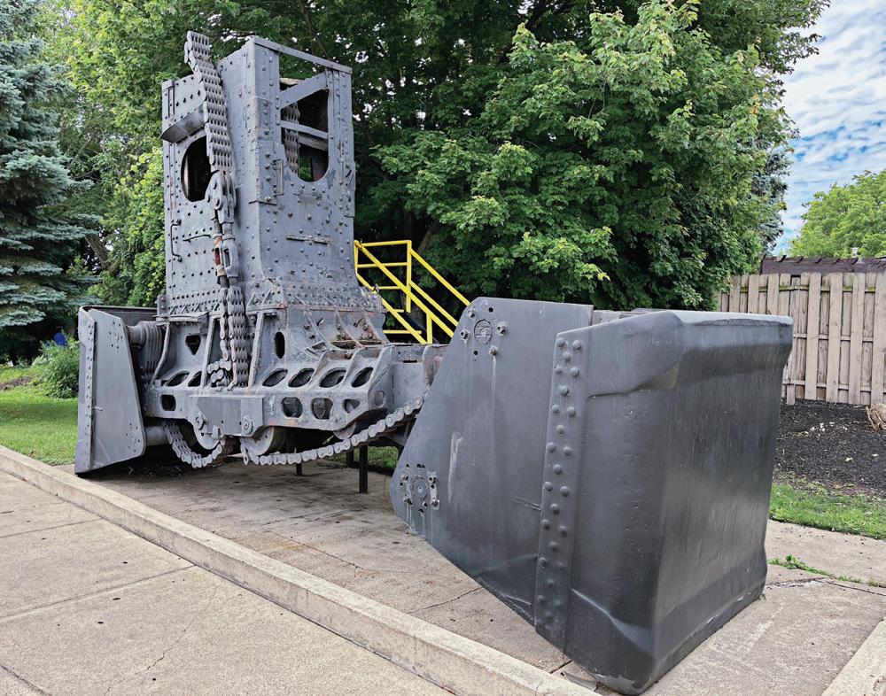
The gigantic steel structure (pictured above) was the combination operator room and leg and bucket mechanism used in Hulett ore unloaders from the late 19th century until the end of the 20th century. These Hulett ore unloaders once dotted port cities throughout the industrial Great Lakes region. They were a time and laborsaving device invented by George Hulett in the late 1890s. It replaced various methods of unloading cargo holds of ships on the Great Lakes, including teams of men using shovels who would be lowered into the holds of freighters to unload iron ore, a job which took days to complete. With Hulett’s new invention, this was cut dramatically to about 8 to 10 hours to completely unload a ship.
I was lucky enough to see a Hulett ore unloader in action several times as they were in the process of being phased out in favor of the new self-unloading ore freighters becoming more common. Seeing them in action was, as the cliché goes, poetry in motion.
They’ve been likened to gigantic metallic dinosaurs, squeaking and squealing, plunging down into a ship’s cargo hold, scooping up 15 tons of reddish iron ore in one motion, hauling it back up and dumping it into railroad cars, then repeating the process until emptying the ship.
To observe these huge machines at work was to be awed by the power and beauty of their elegant motion. But seeing the static display didn’t convey any of that raw magic. One has to imagine what it would have looked and sounded like when these machines were in their prime.
This got me thinking about the power of these and other similar motion machines to inspire awe and wonder in people, particularly future generations of engineers. Being able to see these gigantic, larger than life, impressive motion machines doing their work gives rise to a certain sense of wonder at how they operate, and the thought that went into their design and construction.
That sense of wonder can be activated for young people today by seeing the scale of these machines. And while seeing photos and videos of the Huletts in particular, or even parts of the machines on display, can certainly be inspiring, there’s still no substitute for experiencing one live and in action.
That’s all the more reason why we should support efforts to preserve more of such examples of engineering marvels and achievements of the past, in order to inspire future generations of engineers and scientists. •
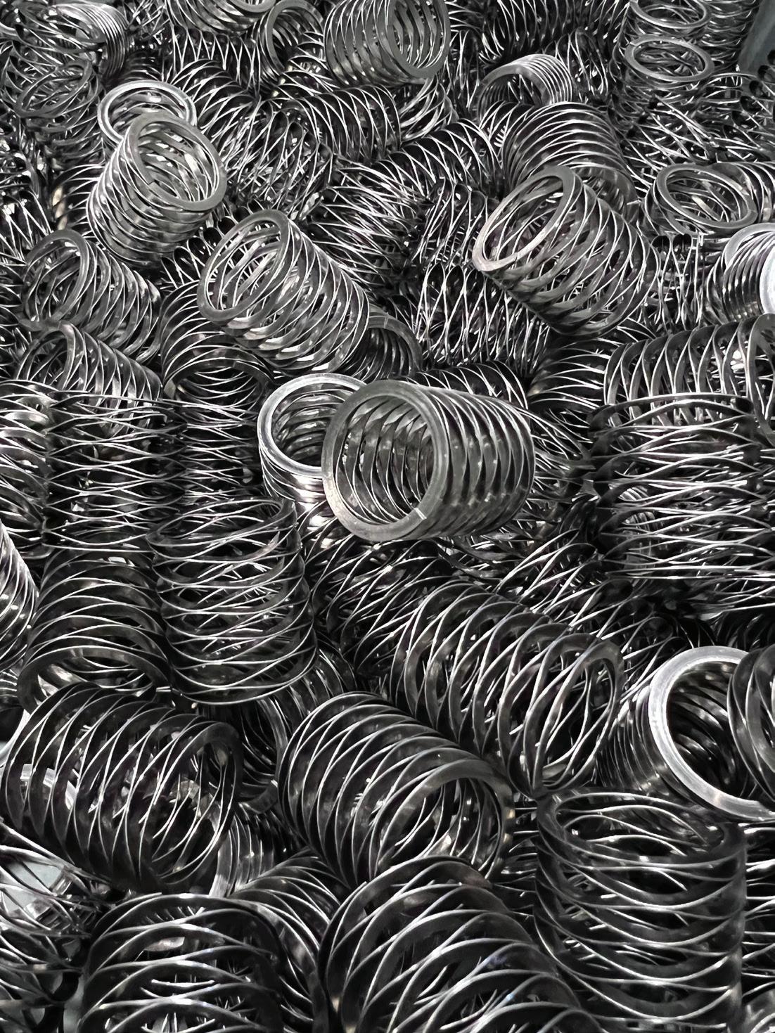
design in the material and size you require. From prototype to production, we'll provide you with the perfect spring solution for your application.

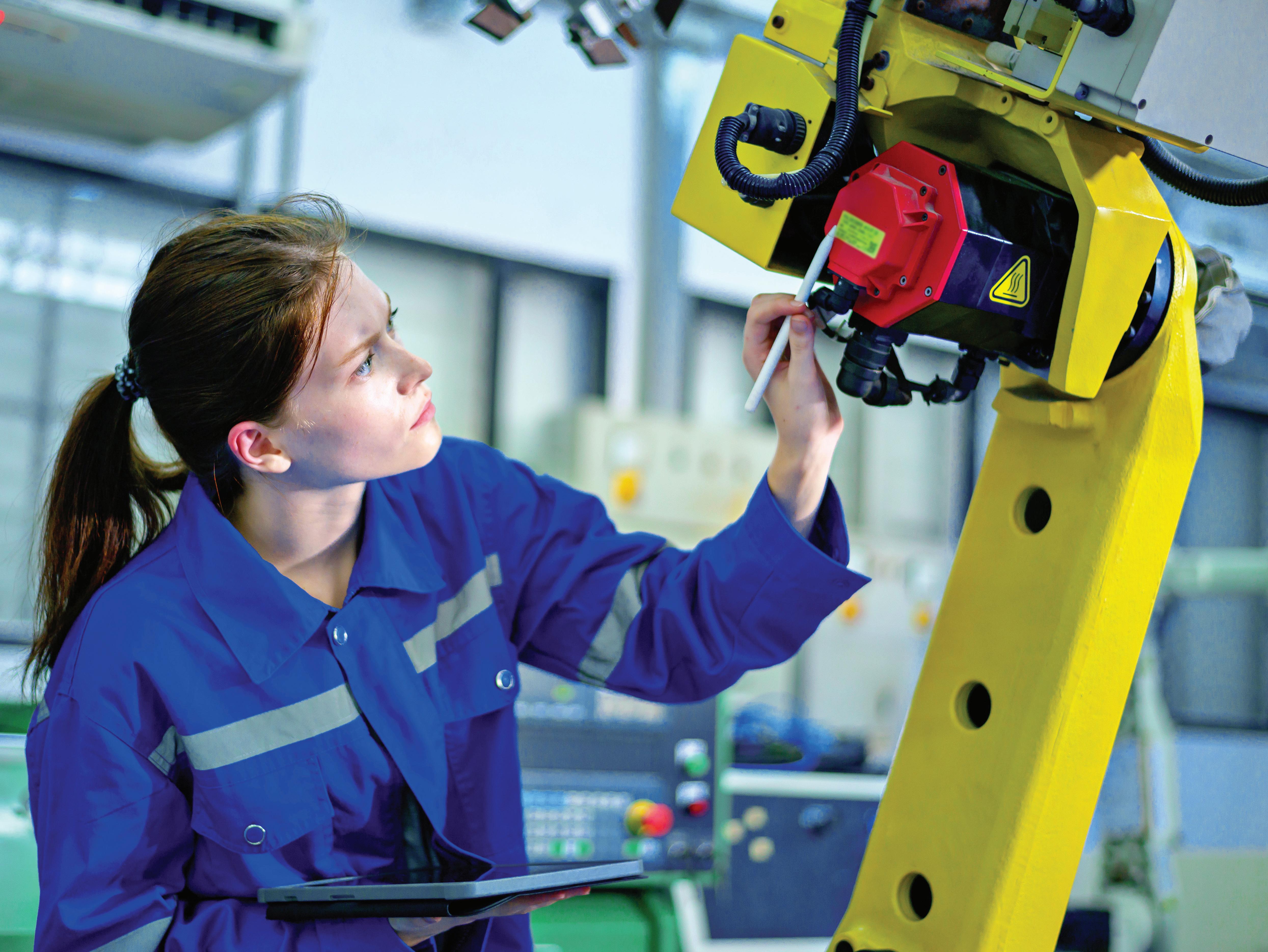
QR codes in documentation and on hardware can load AR-based assistance on an as-needed basis says
BY LISA EITEL | EXECUTIVE EDITOR
Both professional and vocational engineering training are evolving to address skill gaps and workforce-readiness issues.
Advancing communication technologies, the COVID-19 pandemic, and new digital-transformation approaches have forever changed the way technical training in manufacturing and automation is conducted. Now analytics tools can track training progress; adaptive learning can adjust curricula to offer personalized resources; and online collaboration software enables peer-to-peer learning and online classroom sessions. Where training occurs in the field, realtime feedback from IoT-enabled devices can help trainees more quickly understand how to interface with machinery. Finally, the burgeoning field of cybersecurity training has evolved to support endusers requiring digital systems that protect sensitive data and processes. To learn more about these technologies and the specifics of how technical training has continued to evolve, we recently asked several industry experts about their companies’ education efforts. Here’s what those experts had to say.
Remote and so-called electronic learning or e-learning have gained traction over the last 20 years; the COVID-19 pandemic only hastened that trend. Now, many component and system suppliers offer online training modules to let personnel learn at their own pace and revisit engineering topics until subject mastery is achieved. Mobile learning platforms also let workers access training materials for accessible continuous-learning options.
Detail your organization’s efforts to promote technical training since COVID.
GOLDER: The COVID pandemic and its aftereffects have dramatically increased self-education culture. People learned to do all kinds of new things during the
pandemic using the massive amounts of easily consumable online content available on demand on sites such as YouTube and TikTok. So now, people expect 24x7 access to various resources to help them more quickly solve problems without the need to wait for an expert to arrive. After all, sometimes the experts can’t be there in person as quickly as they’re needed.
In response to this trend, Emerson is developing a library of short how-to videos called MicroTrainings that users can access on demand. Each video is less than five minutes long. In them, Emerson experts walk viewers through issues that commonly challenge engineers, operators, and technicians. If a problem arises in the middle of a project or shift, users can get help right then and there. Whether they’re working through an immediate problem or using the videos as a training tool to prepare for the inevitable, people can use MicroTrainings to constantly improve their skills so that in the future, plant issues are less likely to become outages.
RODRIGUEZ: Even before the COVID-19 pandemic, Festo had implemented distributed technologies in our products and operations; e-learning, simulation, remote meeting platforms were used to train users and congregate our own remote teams across continents and time zones.
When COVID-19 hit, we saw education and training significantly impacted across our main customer base as well as at technical colleges and universities. Many of these institutions began implementing remote learning and
virtual training strategies. Luckily, Festo was already positioned with key products — including our fluid-power simulation platform FluidSIM that we began to offer free of charge on a limited basis.
Many educational programs that were not already using these products very quickly transitioned to them. They also began to implement virtual classrooms using tools such as Teams and Zoom which became integral for group projects, discussions, and remote teamwork. This shift let users access training (albeit virtual) from anywhere — enabling flexibility in education and training to proceed despite the pandemic. We also implemented remote access capabilities in some of our equipment so students could access and exercise equipment from home.
Increased adoption of simulation and digital twins (which we were already using before COVID-19 on several platforms) let our endusers virtually design, test, and troubleshoot training products. This reduced the need for physical access to facilities and boosted collaboration across distributed teams.
These changes aimed to adapt to the limitations imposed by the pandemic while leveraging technology to maintain educational training for our endusers along with uninterrupted collaboration among our own design, engineering, sales, and manufacturing teams.
B. BURKE: Bishop-Wisecarver University is an online training platform that we utilize internally to provide role-specific training courses for new hires … and
Brian Burke ...................... Product manager III Bishop-Wisecarver Corp.
Brian Dengel General manager • KHK USA Inc.
Chris Caldwell.................. Product manager – material handling Yaskawa Motoman
Daniel Rodriguez Sales director — didactic Festo
Emily Blanchard ............. Senior global commercial training specialist Kollmorgen
Josh Leath Senior product manager — thermal Yaskawa Motoman
Lauren Griffith ................. Director of learning and development Schaeffler Americas
Mike Korkowski Operations manager LinMot USA
Nina Golder VP of global lifecycle services Emerson
Robert Cachro Program manager — growth and innovation • Dynapar
Sebastian Werler Head of product management and software development — digital business • Festo
to grow the knowledge of our existing workforce. BWU is an online platform with a growing list of courses that lets employees schedule learning at their own pace. This platform was vital during COVID restrictions because new hires could receive quality training based on our industry knowledgebase. Now, as an extension of the platform, BWU is expanding to in-person face-to-face training for new hires.
CACHRO: Before the pandemic, Dynapar heavily relied on in-person sessions, hands-on workshops, and live demonstrations for product training. However, the onset of COVID-19 prompted a swift shift to virtual platforms. This adaptation was a response to the immediate challenges of the pandemic as well as a strategic move emphasizing self-service approaches to education. Key elements of this transition include …
Digital video tutorials: A significant initiative has been the creation of comprehensive video tutorials, exemplified by those for the HS35iQ product launch. These tutorials are self-paced to let learners access and revisit the content as needed, from any location and at any time.
Webinars and virtual workshops: Traditional in-person events have been largely replaced by live webinars and virtual workshops. These sessions often feature Q&A segments to foster realtime interaction with experts.
Product certification and partner empowerment: The HS35iQ Champion
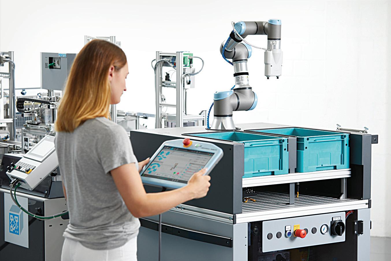
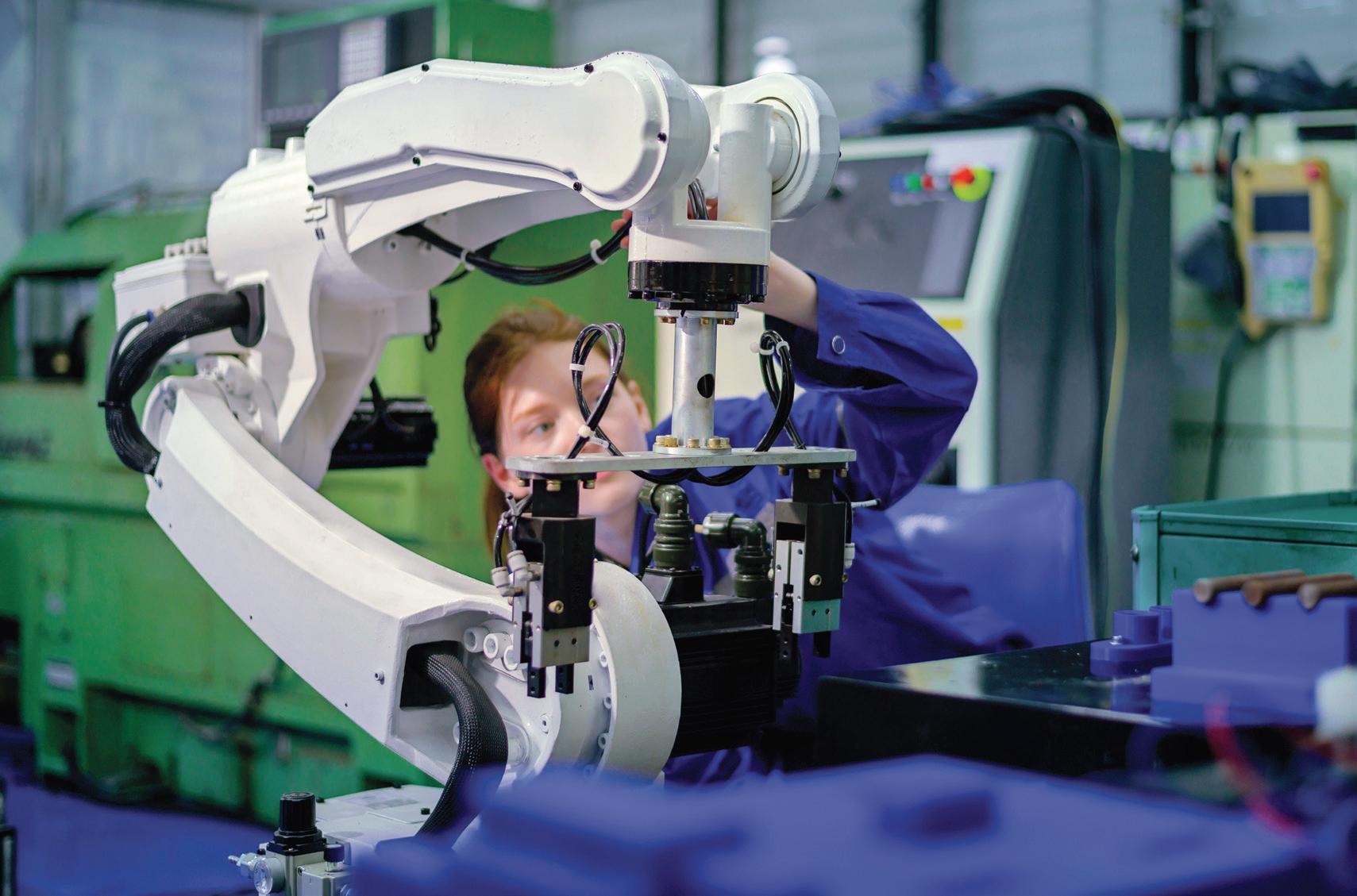
FAR LEFT:
Utilizing a blended learning model, Festo Didactic training services are customized and implemented through various modalities, including e-learning, instructor-led sessions, virtual experiences, and as shown here hands-on activities.
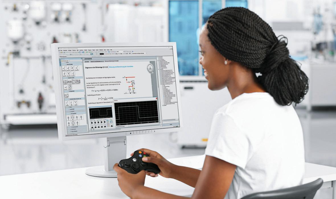
LEFT:
Festo LX offers a holistic approach to technical education and training, featuring a wealth of professionally developed learning content coupled with relevant practical applications. Its innovative blend of e-learning courses and hands-on exercises ensures that students are well-prepared for the demands of today and those of future high-tech industries.
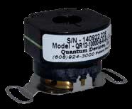

Since
We
from the ground up, with design and manufacturing on-site allowing us to offer custom, high accuracy encoders plus applicationspecific models.
Program is central to our new strategy. It serves to acknowledge professional skills and promote ongoing learning. Furthermore, it provides a unique opportunity for partner distributors to achieve HS35iQ Champion status. This status lets them offer our products at reduced prices and positions them at the forefront of digital transformation. The program is designed to enhance our partners’ understanding of our products and strengthen their sales skills, giving them a competitive advantage in the market.
Now, our focus is on creating remote learning experiences that are just as effective as in-person formats. We aim to ensure that all participants, regardless of their location or circumstances, have equal access to high-quality training resources.
Those interfacing daily with automated machinery must know how to operate it. Other modes of understanding are required for those who service or sell parts to be integrated into such equipment. Personnel in such roles rely on vocational training.
Rebounding enrollment and debates about higher education in North America haven’t entirely quelled persisting stigmas associated with trades-type work, even in automation. But demand for skilled tradespeople in the U.S. remains high in new manufacturing, automation, infrastructure, energy, and distribution operations. New training programs are key to preparing workforces for digitally transformed engineering and manufacturing operations.

• Standard optical encoders featuring numerous configurations
• In
• Small to medium batch custom photodiodes from our own silicon foundry
• Custom caliper [ring] encoders for large bores--starting at 1”; incremental and commutation options available
Describe your certification or upskilling programs to educate engineers and other personnel — including technicians, distributor sales representatives, and endusers. GRIFFITH: Schaeffler offers a suite of learning programs through our in-house Schaeffler Academy. We recognize industry trends and are focusing on the future business needs through our Fit4… learning series, which
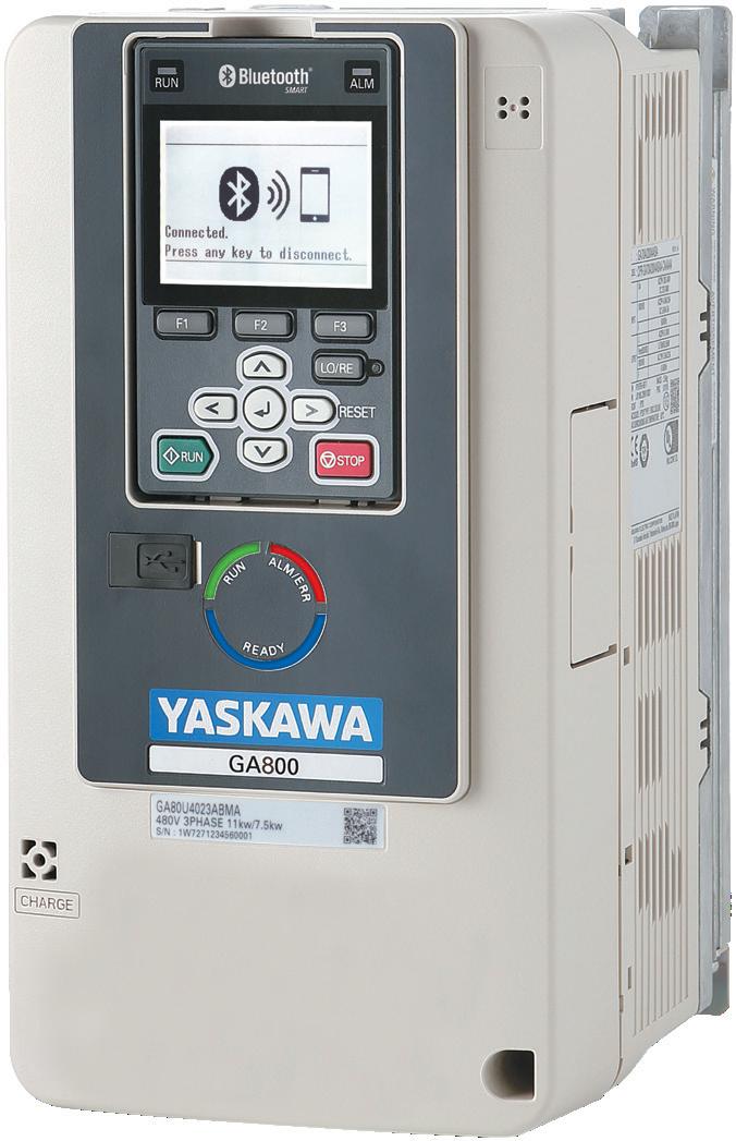
Your time is valuable. The easy-to-use GA800 AC Drive from Yaskawa gives you the power to make all of your operations better.
• Rest easy with legendary Yaskawa quality and embedded functional safety.
• Experience ultimate ease-of-use with DriveWizard® Mobile and optional Bluetooth® connectivity.
• Enjoy incredible torque production and network connectivity.
Your days are complicated enough. Let us help simplify them. To learn more, visit or call Yaskawa today at 1-800-YASKAWA.


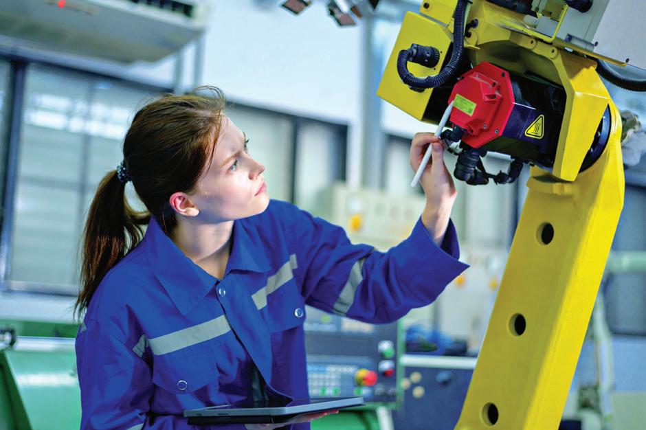
In the wake of COVID, employees are craving face-to-face interaction and learning from on-the-job enhancements, says Lauren Griffith, director of learning and development at Schaeffler Americas.
Fit4Mechatronics (providing technical skills for our engineers as we shift to boosted electrical production), Fit4Production (providing a strong foundation for non-degreed personnel to enhance technical skills), and Fit4Digitalization (providing digital skills for increasingly innovative business).
During COVID, we used a combination of iPads, Go-Pros, and security monitoring devices inside machines to let employees (as part of their technical development) learn processes and troubleshoot directly from a computer (instead of on the shop floor). This significantly lowered the risk of infection. Although the systems and tools created during the pandemic have proved invaluable, we’re now transitioning to standard blended learning components.
BLANCHARD: Kollmorgen creates learning programs leveraging cognitive neuroscience — a combination of psychology and neuroscience. For more than 15 years, we’ve offered an online channel-engagement program providing short monthly touchpoints based on job function for sales and application engineers. Using monthly touchpoints
keeps Kollmorgen technology, processes, and thought leadership on a cadence that prevents learning degradation.
In addition, our hybrid and instructor-led courses use online modules to prepare students for precious instructor time so they can focus on hands-on instruction, practice, and troubleshooting. With online modules already in place, we were well positioned as COVID struck and quickly implemented an online seminar program addressing many learners — including endusers, our distribution channel, and our employees. Post-COVID, we continue to expand our mix of online offerings while utilizing valuable inperson sessions to their fullest interactive experience.
GRAHAM: Our team has a comprehensive training program for OEMs, distributors, and endusers. Through training, we help individuals develop expertise in the installation, connection, implementation, networking, calibration, maintenance, and servicing of HEIDENHAIN components and automated systems. Our courses cover setup and optimization, software adaptation through PLC and Python

Post-COVID, we continue to expand our mix of online offerings while utilizing valuable in-person sessions to their fullest interactive experience, says Emily Blanchard, senior global commercial training specialist at Kollmorgen.
programming, and diagnostic and servicing. More information is available at heidenhain.us.
SACHDEV: To help our endusers, OEMs, and integrators, Cognex recently launched a new Getting Started website that provides step-by-step training videos and FAQs as well as connection help for external systems and additional software utilities. We’re committed to making machine vision easy, and this site is part of that commitment.
For more complex deployments, we offer even more education and support to ensure long-term success. For sophisticated logistics environments, for example, we provide support packages
that include analytics and data to optimize overall system performance as well as training and coaching for operators and maintenance staff — plus dedicated setup help to get new systems up and running.
Any continuing-education offerings?
KORKOWSKI: LinMot provides inperson training at our facility several times a year. We’re also exploring e-learning. Our product representatives are technically knowledgeable on all our products and given continuous learning; regular sessions are conducted to keep representatives updated on new products and improvements. Special training is available to endusers on an as-needed basis.
RODRIGUEZ: Industry is in constant evolution, embracing new technologies for increased efficiency, sustainability, and productivity. This has been true since the early days when the fi rst human used a stick plow to more effectively cultivate land. For nearly a century, Festo has been at the forefront of driving industrial progress. However, the rapid pace of change poses challenges in keeping up with advancements. Our industrial endusers emphasize the need for qualified workers to leverage our technologies and maintain competitiveness in the global economy. Festo and Festo Didactic (our education and training division) are committed to identifying gaps and employing our training solutions to
cultivate an agile and flexible workforce.
Conducting comprehensive diagnostic assessments of factory-training needs lets us tailor our approach to specific requirements. We also specialize in pre and post-employment skills assessments to provide valuable insights for comprehensive workforce development.
Utilizing a blended learning model, our training services are customized and implemented through various modalities, including e-learning, instructor-led sessions, hands-on activities, and virtual experiences. Our tailored training programs and on-site courses prioritize hands-on lab instruction, constituting a significant 60% to 70% of the learning experience. This focus on hands-on
practice enhances retention and overall performance.
The online portal of Festo Learning Experience (Festo LX) offers a holistic approach to technical education and training with a wealth of professionally developed learning content coupled with relevant practical applications. Its innovative blend of e-learning courses and hands-on exercises ensures that students are well-prepared for today’s demands and those of future high-tech industries. Our instructors bring industry-specific expertise and experience to the table, aiding in the cultivation of a multi-skilled workforce capable of adapting to dynamic business changes.
Finally, we advocate for a lifelong learning approach, encapsulated in the concept of K-to-Gray. This involves STEM programs for early learners, integrating
science and technology into every young person’s experience. Collaborating with technical colleges and secondary schools to create pathways aligned with industry needs, coupled with an industrial community offering advice, mentorship, and support at all education levels, completes the holistic solution.
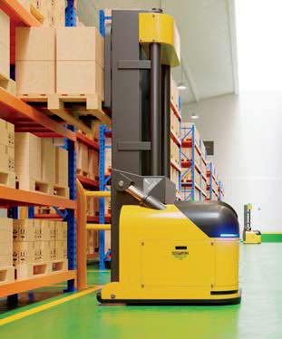
RODRIGUEZ: Intralogistics with respect to material handling, warehouse management, and automation technology is one of Festo’s focus sectors. We see several trends shaping data digitalization in warehousing. The skills gap and labor shortage in this sector grows every time a new warehouse pops up in a neighborhood.
Warehouses today are highly automated but require a great deal of
support to install, operate, program, and maintain. Automation technologies such as robotics, AI, and IoT devices are increasingly integrated into these operations. These technologies not only streamline processes but also generate vast amounts of data, offering insights into inventory movement, picking patterns, and operational efficiency.
IoT devices and sensors are used extensively to track and monitor inventory in realtime. They provide data on factors such as temperature, humidity, location, and condition of goods, enabling better inventory management and predictive maintenance. That said, once a problem occurs, it needs to be corrected and repaired by a human. Warehouse operations are adopting digital twin technology, creating virtual replicas of physical warehouses. This allows for

With a comprehensive line up of encoder solutions, Renishaw brings the expertise needed to address your manufacturing challenges. Whether your application calls for optical, magnetic or laser technology, our encoders achieve the highest levels of accuracy, durability and reliability.
Powerfully positioned for innovative motion control.


With decades of combined experience and industry expertise, we provide our customers with multiple solutions and products from one source to help create a better tomorrow. This also extends to working in partnership with our customers to solve your problems. We are ready to show you what we can achieve together.


simulation, testing, and optimization of processes before implementation, reducing risks and enhancing efficiency and the Festo learning platforms integrate and develop skills in these technologies. In addition, with increased digitalization comes the need for robust cybersecurity measures, so we cover that in our training programs as well.
These trends in data digitalization are transforming traditional warehousing practices, making operations more efficient, and agile — and starved for the human talent to make them work.
An array of companies has expanded North American vocational training in recent years — especially to support
advanced manufacturing operations. These companies include many of the automation suppliers Design World surveyed as well as Rockwell Automation, Schneider Electric, FANUC America, and Eaton. Many of these programs were modeled after European programs or developed in partnership with local community colleges serving students from communities that are underrepresented in automation and manufacturing. In a few cases, Biden-Harris Administration investments in workforce development (through Perkins funding) have expanded this type of career-connected learning to bridge the divide between K-though-12 school systems and industry internships.
How are you supporting education at the local level and addressing labor shortages?
KORKOWSKI: We’re partnered with
several local high schools and universities to expose young people to the benefits of industrial automation.
GRIFFITH: We internally and externally develop our workforce by participating in school STEM programs to engage students with our company and industry at an early age. That has the potential to increase our pipeline of people capability. Early-career development opportunities include apprenticeships, co-ops, and engineering-focused development programs. The pandemic forced the general training industry to be more virtually inclusive, which has rendered Schaeffler’s training opportunities more accessible — thereby enhancing the speed and pace of delivery to put the content in the hands of the users through live online trainings at all locations in the region (instead of just local course offerings).

Over seventy percent of the gearmotors we build are customized. From wiring harness to windings, we will modify our products to meet your design specifications. Minimum order quantities apply. Visit bodine-electric.com/custom-solutions

RODRIGUEZ: For starters, the only way to address our labor shortages and the skills gap is through training. The notion that technology offers new solutions to address persistent skills gaps across industries is not new, and Festo has been keeping pace with this evolution throughout its history.
Festo quickly began to automate its woodworking machine tools shortly after one of our founder’s sons returned from the 1933 Chicago World Fair, billed as the Century of Progress International Exposition. The new technology in question was pneumatics and the idea was to automate machine tools Festo was building. Soon it became apparent that both our users and machine designers needed to be trained on the new technology. Festo Didactic was born to implement automation being used to fi ll labor gaps, assume repetitive tasks, increase efficiency, and reduce human labor in some roles.
Since then, it’s been a constant evolution of adapting to the changing technological panorama, using the tools of the day to do it. Today, part-time remote-learning options let trainees gain theoretical knowledge before attending
a hands-on session. With such offerings, we’ve accessed a worker that may have been unable to attend a full-time training program. These options let companies and schools tap into a wider pool of talent beyond local geographical boundaries.
Festo is also leading the training field in integrating cobots that work alongside humans, assisting in tasks that require human dexterity or decision-making. This is just another tool to increase productivity and overcome labor shortages.
GRIFFITH: Because manufacturing is an ever-changing industry with new technologies and modernization occurring daily, Schaeffler cannot be successful without a culture of continuous learning. Our plants’ onsite technical trainers are responsible for partnering with our in-house subject matter experts on new trends, updating an on-the-job and qualification database to track skill enhancement, and ensuring compliance. All of this starts with creating partnerships with community workforce boards and educational institutions, so that we can ensure that the material being taught in schools matches the current and
future needs of our business. Doing so improves onboarding speed for technical roles and allows Schaeffler to be an industry leader.
Any local or regional education programs you particularly admire?
RODRIGUEZ: Answering this question is difficult because there are many creative and unique approaches to the problem. What I fi nd most admirable is genuine collaboration across the various education levels, spanning from primary to secondary schools, colleges, and the industrial and commercial communities they serve. School districts are now incorporating STEM and technicalvocational programs, establishing pathways to both employment and further education.
The traditional emphasis on a four-year degree as a prerequisite for a successful and economically viable future is, in my opinion, gradually diminishing. Instead, there’s a growing recognition of education as a continuous series of steps throughout a worker’s life. This perspective is gaining traction, with an increasing focus on practical, lifelong learning.
It all begins, however, with a strong academic foundation and the development of collaborative problem-solving skills. As we see these shifts in education and the acknowledgment of diverse paths to success, a more dynamic and adaptable approach to learning is taking root.
VARLEY: At Mitsubishi Electric Automation, we have an entire group dedicated to workforce development. We’re involved with program throughout the country ranging from high schools to trade schools to four-year colleges and universities. All our product groups contribute to this effort to deliver both hardware components and classroom materials. We see this trend continuing and expanding in the years to come.
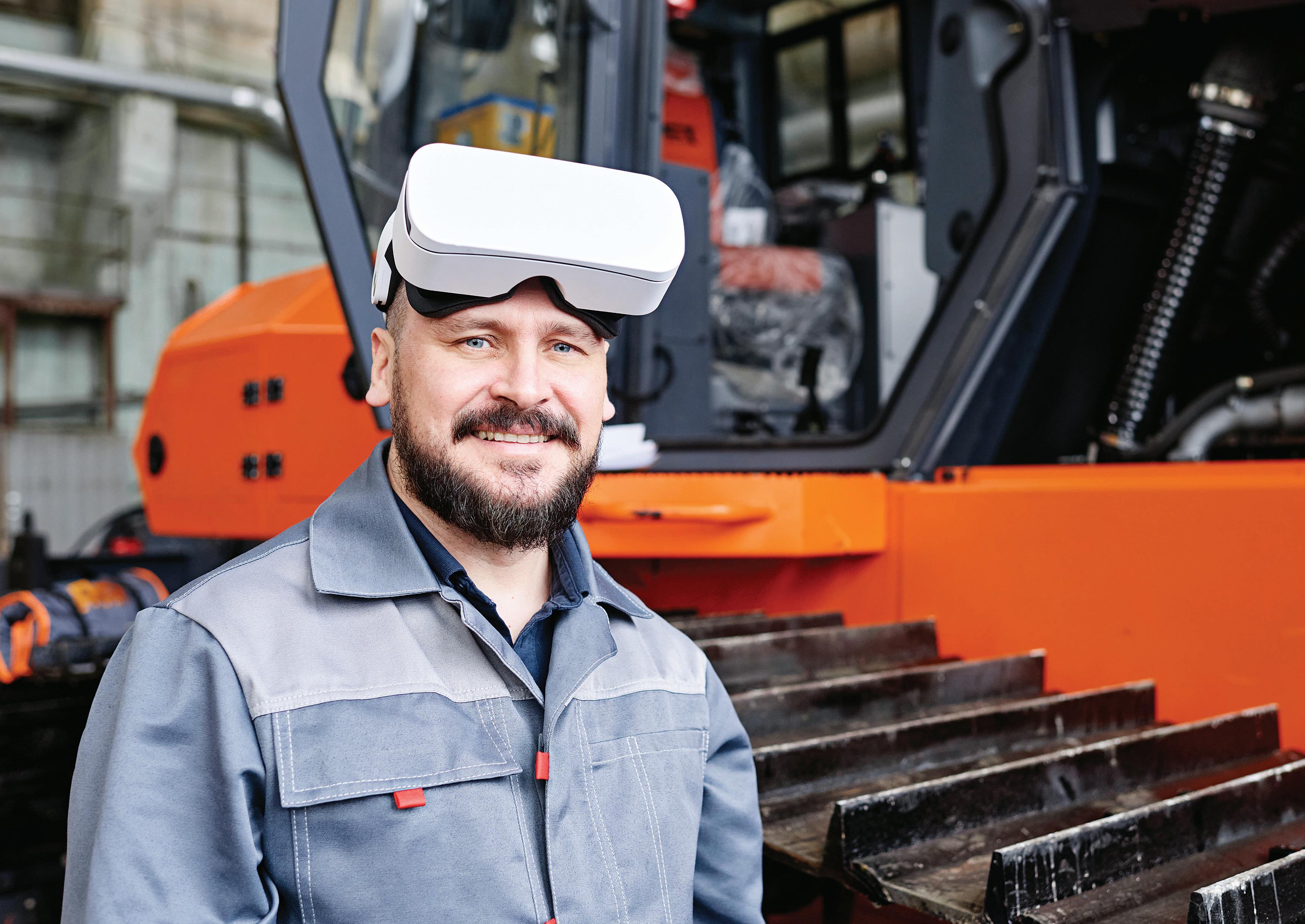
Once relegated to novelty video-game applications, virtual reality (VR) is seeing modest adoption for immersive technical
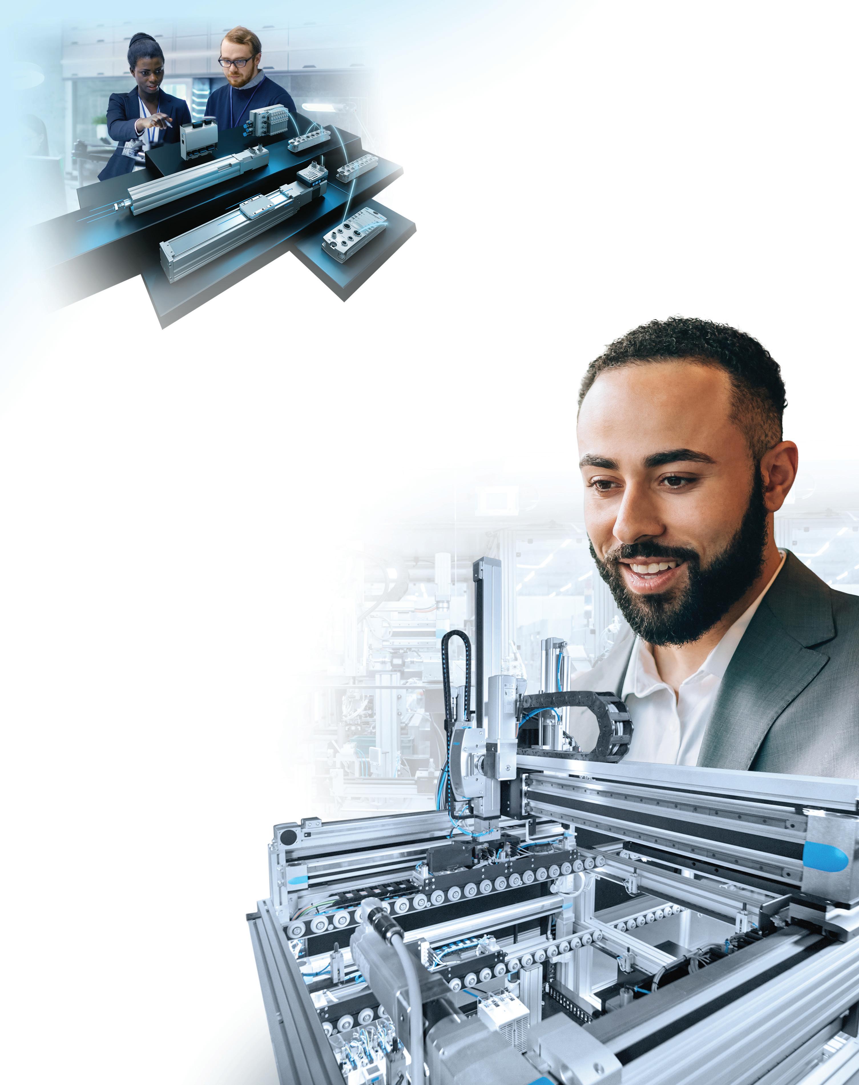
Realize your vision with Festo’s approach to smart automation. Partner with Festo today.
Superior
Global

training, especially where personnel must be trained to interface with manufacturing environments or very large and complex designs. Likewise, the digital overlays of augmented reality (AR) are now seeing more use to help trainees navigate physical environments during hands-on training, especially where it’s important that personnel feel comfortable with a particular setting.
Sometimes these tools are complemented by modules featuring learning management systems (that tailor modules to individual learning needs) and gamification (that feature special challenges, badges, and leaderboards to make learning more fun).
The virtual models (digital twins) of physical machinery and processes spurred by digital-transformation initiatives have also found use in training programs — especially those for maintenance personnel. Such use of digital twins is most useful where (for whatever reason) it’s difficult or dangerous to let trainees interface with actual equipment.
Are VR, AR, and the metaverse becoming more applicable to technical training?
LEATH: VR and AR are currently used in many industries for training. I could see more application training or maintenance instructions being done with VR or AR for the robotics space — to let users learn and experience a task before actually doing it on live equipment. Also, as more humanoid robots appear in the marketplace, I expect many will be driven by real humans remotely steering such robots via VR gear.
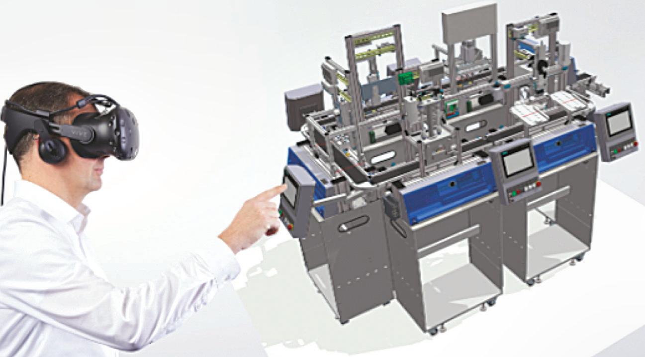
RODRIGUEZ: Festo actively uses the metaverse as a virtual shared space that includes technologies such as VR, AR, artificial intelligence (AI), cloud computing, and the internet. These technologies stopped being science fiction long ago, and we’ve been using them in training as technologies advance.
In fact, Cloud Technology is a key element of our Industry 4.0 training. Augmented-reality links in our hardware let trainees see the inside of a valve or a motor — things that otherwise would’ve been impossible.


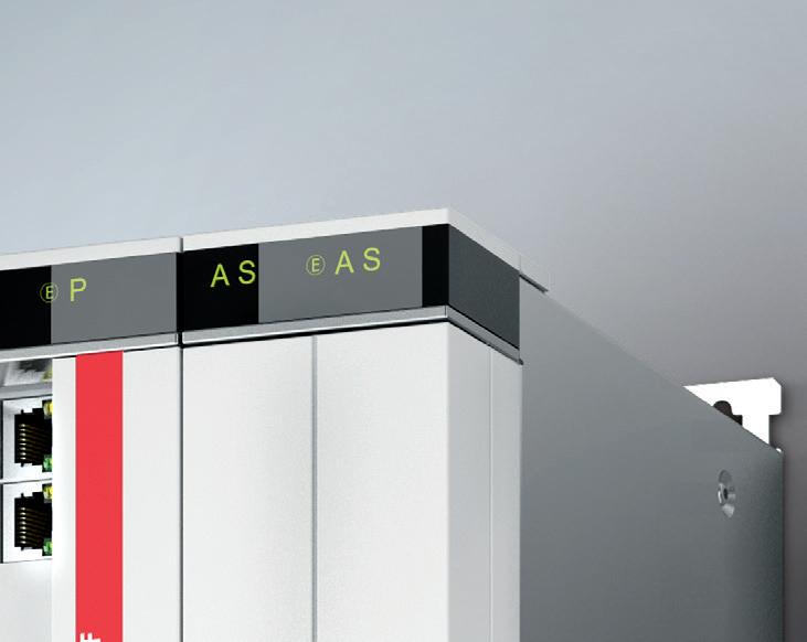
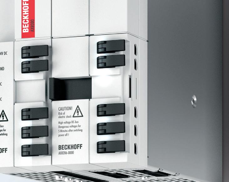
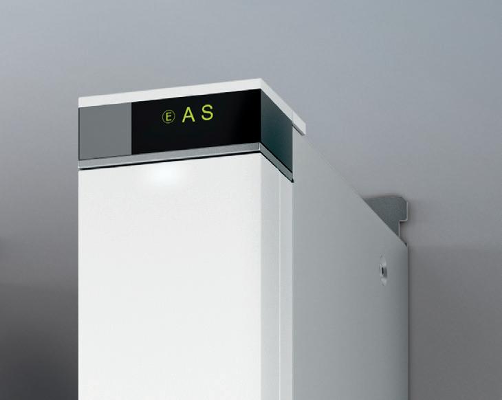
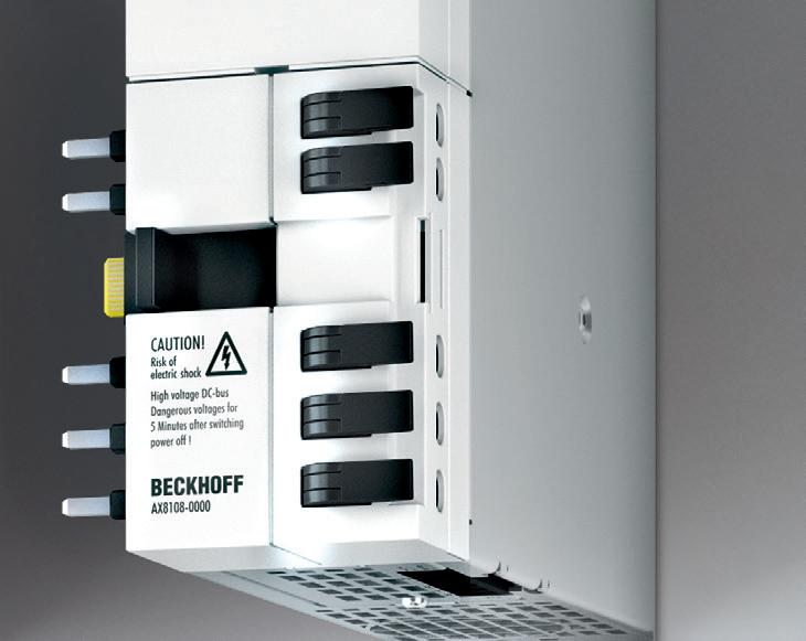
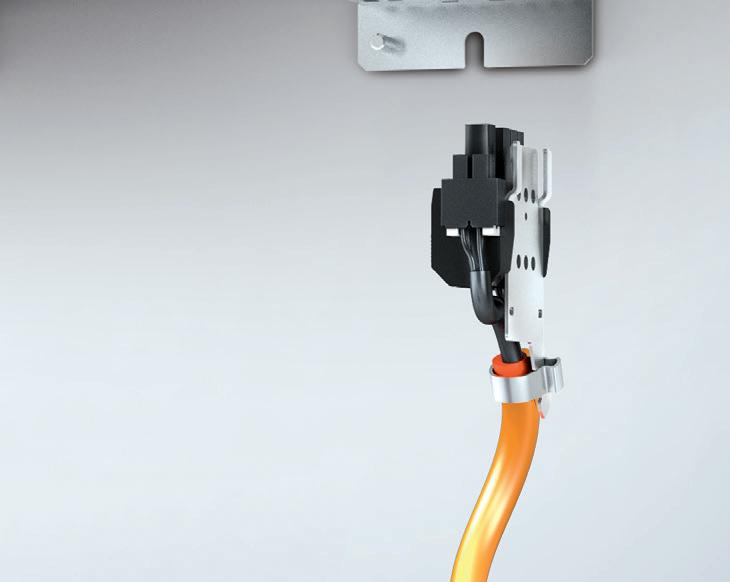
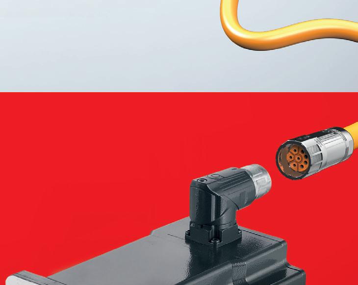
Extremely compact, superior performance, and seamless setup! The AX8000 multi-axis servo system from Beckhoff optimizes not just operation, but also installation in 3 easy steps:

1. Fast, gap-free connection of drive modules via the AX-Bridge system – with zero tools required
2. Safe and simple motor connection with user-friendly plug connector on the underside of the drive
3. Reduced number of cables and lower installation cost with One Cable Technology
How else does AX8000 simplify servo system implementation? With high precision and performance – through real-time EtherCAT communication. And safety – through 17 drive-integrated TwinSAFE functions. Sounds pretty easy, right?


Apple Vision Pro will come to dominate for high-end VR and AR applications and commodity glasses with integrated AR software will become most common in lower-end applications predicts Sebastian Werler, Festo’s head of product management and software development — Digital Business.
Festo software, including Ciros and FluidSim, empower users to craft and contribute content to the metaverse — to shape the environment and experiences for both themselves and others. With the metaverse, Festo can offer a diverse range of applications for training, certification, and upskilling across fields such as mechatronics, electric power, renewable energy, biopharma, and telecommunications with the added benefit of reaching distant populations with our training materials.
Beside VR training simulations,
Festo can enhance technical skills development such as programming, engineering, and other fields that benefit from metaverse platforms … for example, offering coding environments or 3D modeling tools that let learners practice and experiment in a virtual space.
Certification programs for trade skills and vocational training that use online courses leveraging the metaverse (to simulate real-world environments, tools, and scenarios) offer engaging and interactive learning experiences. These enhance the other hardware and lab-based
programs for which we’re known.
Finally, AR applications overlay digital information onto our real-world programs. That makes tasks such as maintenance training (where instructions or guidance can be displayed onto real equipment) more effective.
These uses demonstrate how the metaverse can revolutionize traditional training methods by providing immersive, interactive, and adaptable learning experiences.
GRIFFITH: While the metaverse certainly
AR and VR tools are not in use; we have welding simulators, forklift driving courses, and even customized machine learning in some of our facilities.
WERLER: We employ digital learning and training supported by AR and VR to create human-centric workplace designs and pretest assembly stations. In addition, these technologies support maintenance and repair job functions … and make workflows partly automated by supplying timely information to personnel — thus adding value at the right place and time.
HALSTEAD: VR can be used to speed up product design. After all, these tools can help individual designers visualize systems and (more importantly) share their vision with their team to greatly improve end results.
users mimic application motions — so for example, the operator holds the wand and goes through the motions of welding a part. The release of the wand was followed by an intuitive software package that feels more like a slick iPad application than a programming interface.
RODRIGUEZ: Collaboration tools facilitate seamless communication and teamwork among remote workers, allowing companies to access skilled professionals who might not be locally available. AR and VR technologies can enhance training processes, allowing employees to learn new skills or procedures in a simulated environment. This can expedite the onboarding process and make training more accessible and effective.
How have you seen increased use of human-centric design over the last year?
CALDWELL: Human-centric design is paramount to Yaskawa because ease of use is important to robotic expansion for all user levels. Many of the tools we’ve developed are meant to ease the installation and use of robotics. One area in which we’re continually experimenting is AR adoption for our manuals and maintenance offerings. Here, QR codes in documentation and on hardware can (when scanned) load AR-based assistance on an as-needed basis.
provides opportunities to enhance the learning experience using simulations and avatars, Schaeffler has not yet made investments in the equipment to scale these programs. Given the fact that large percentages of our workforce are shop-floor employees, we tend to lean toward traditional e-learning (sometimes gamified) to help us set standards and build consistency. In the wake of COVID, we have found that our employees are craving face-to-face interaction and learning from classroom or on-the-job enhancements. This is not to say that
B. BURKE: I expect to see to continued adoption of AR and VR to streamline production for a more flexible workforce — and to make production instructions more robust.
DENGEL: AR and VR can be tools used to teach assembly personnel or maintenance personnel how products work, thereby reducing the time needed for training and troubleshooting.
LEATH: More and more lead-to-teach intuitive technologies have been hitting the market to appeal to skilled workforces and younger generations. For example, the Wandelbots wand helps
WERLER: Yes, Festo fi rst used its Bionic Learning Network (to study exoskeletons, soft grippers, self-adjusting workplaces, and more) a decade ago. Employing such software along with agile processes and minimum viable product concepts helps us review customer needs and continuously develop to deliver humancentric designs. Our Smartenance maintenance software is a perfect example here … and it was developed in partnership with production staff. Another example is the GripperAI. This design leverages neuronal-network-based DL software that lets cobots and robots detect and grip any unknown object — even when changing robot tools — to support (or collaborate with) workers in logistics settings. •
Many applications call for the use of electromechanical linear actuation — which includes electric motors paired with various mechanical components for controlled movement of equipment or payloads. Options for linear actuation have proliferated in recent years. Actuators and linear-motion options today are also easier than ever to integrate into machinery ... and they’re often less costly than in the past.
Most linear actuators turn an electric motor’s rotary power into linear motion in one of three ways: Through a rack-and-pinion set; through a chain or belt (via a sprocket or pulley mounted to the motor output); or through a screw drive — whether ballscrew, leadscrew, or roller screw.
A fourth option for linear actuation is linear motors — a technologically advanced direct-drive method of transmitting motor power into axis motion. These entirely omit the mechanical linkage for rotary-to-linear conversion and instead include a moving forcer that moves along a stationary platen.
Linear actuators come in myriad configurations to suit almost any application, environment, or industry. They’re primarily


categorized by their drive mechanism; then manufacturers use other features such as the type of guide and housing to further differentiate them. Below is an explanation of the most common linear actuator categories.
Belt and screw-driven actuators: Although belt and screw drives are different technologies, it makes sense to put them in the same category because they are the two most common types of electromechanical actuators. Most manufacturers of linear actuators offer both belt and screw-driven options.

PLANAR ERRORS AFFECT ADJACENT AXES ...


Belt-driven actuators can use a variety of guide mechanisms ... plain bearings, the more advanced option of wheel-based linear guides, and recirculating bearings (riding on a profi led rail or round shaft) are most common. Because their strengths are high speeds and long strokes, belt-driven systems are often housed in an aluminum extrusion or in an open configuration with no protective housing.
Within the linear-screw category, there are two subcategories — ballscrew and leadscrew drives. While ballscrew actuators have higher repeatability and thrust forces than leadscrew actuators, both provide inherent gearing through the lead (pitch) of the screw.
The most common guide system for screw-driven actuators is the profi led rail, although leadscrew types are sometimes guided by plain bearings. Because screwdriven actuators require end bearings that must be rigidly mounted, they are often enclosed in an aluminum extrusion. However, when high travel accuracy is required, ballscrew types are commonly offered with a machined steel housing.
Ballscrew actuators also pair with track-roller linear guide mechanisms on high-speed axes and those to deliver high thrust force.
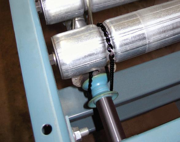
Pneumatically driven linear actuators: Although they’re not electromechanical devices like the other actuator types, their prevalence in automated equipment makes pneumatic driven versions an important category of
linear actuators. Pneumatic actuators can be further divided into two sub-categories … slider-type and rod-type.
In slider-type actuators, the motion is contained within the limits of a housing and the load is mounted to a slider — also called a carriage, saddle, or table.
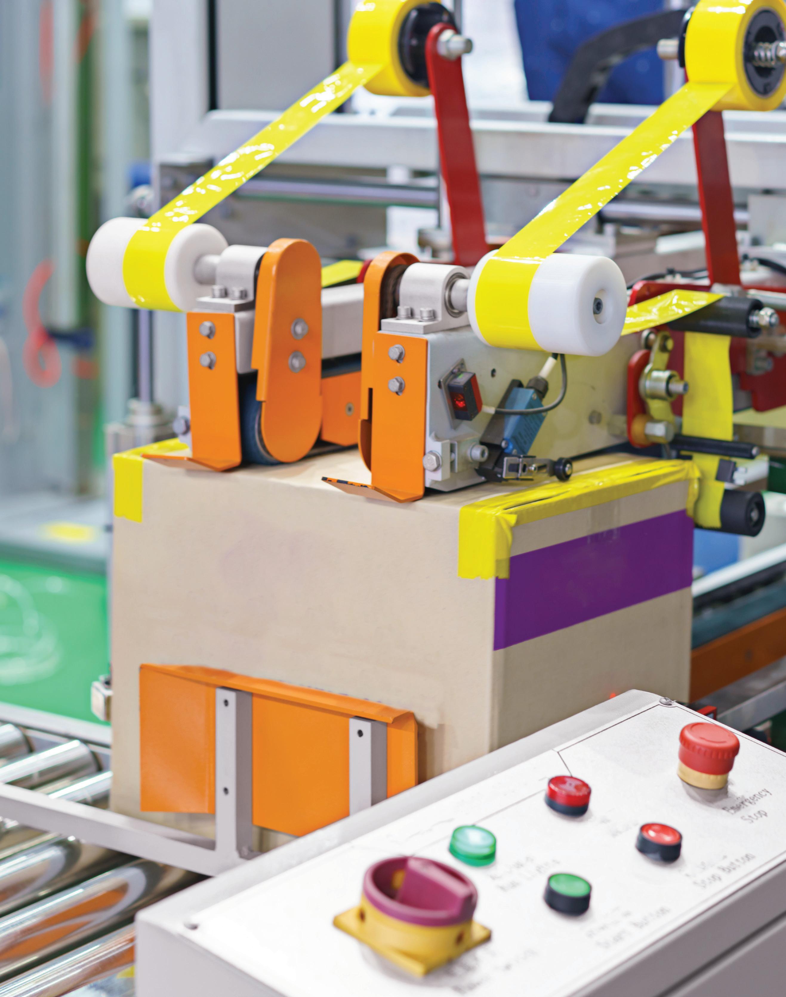
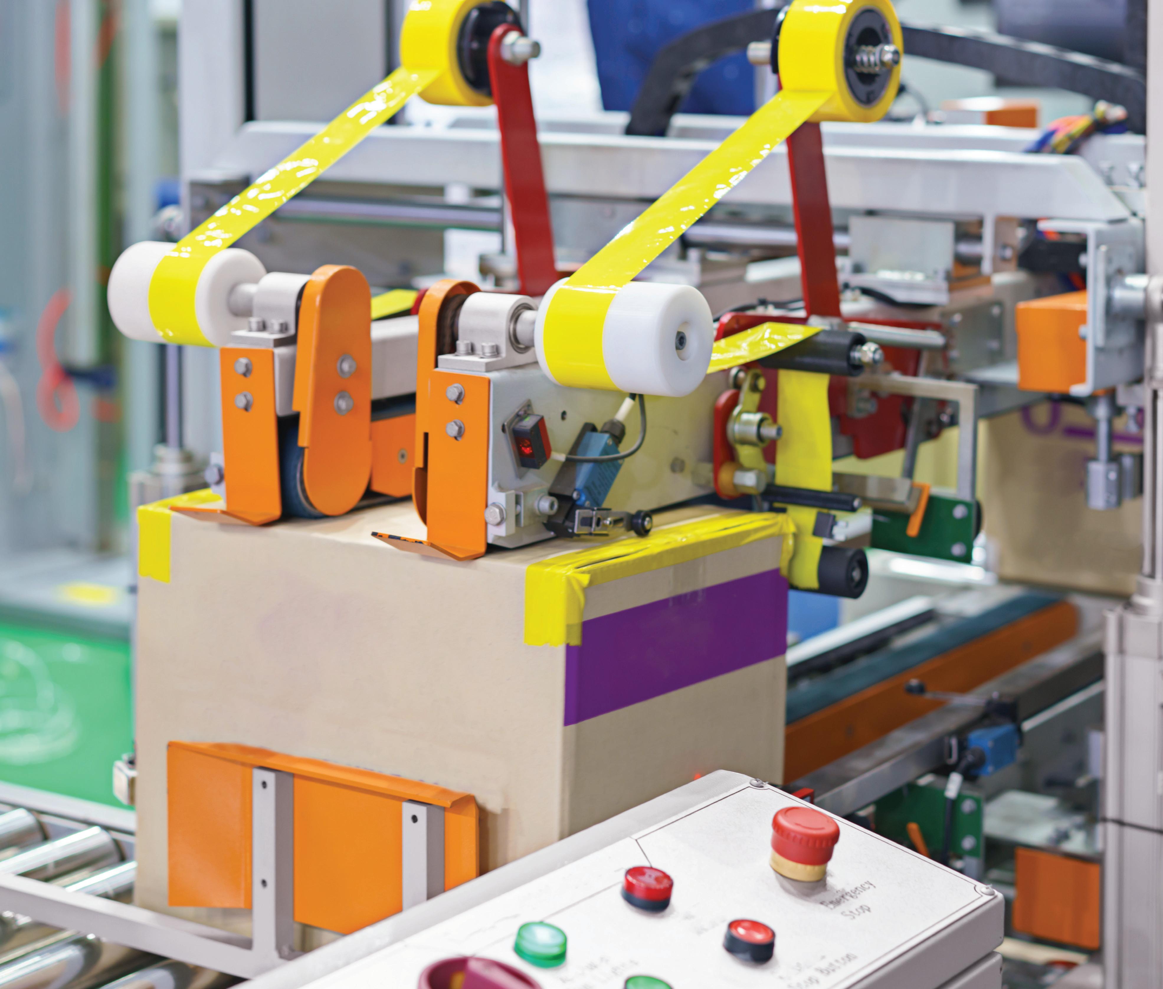
In rod-type actuators, the motion is produced by a rod that extends and retracts from a housing. The load may be mounted to the end of the rod or the rod can be used to push the load. One common application is the pressing or stamping of labels onto cartons … or pushing defective products to a diverter lane along a conveyor.
Slider-type pneumatic actuators can be guided by recirculating or plain bearings, depending on the load for which they’re designed. In contrast, rodstyle versions are not typically designed for radial (downward-upward-side) loads and use simple plain bearings to provide guidance to the rod without significantly contributing to load-carrying capacity. Note: Ballscrew-driven actuators also come in slider and rod-types, making the actuator family tree even more complex.
Chain and rack-and-pinion driven actuators: For extremely long lengths and robustness against contamination, chain drives and rack-and-pinion drives are often the most suitable choices. Joined profi le rails are sometimes used with these drives. However, in settings with a lot of debris, these actuation systems

are best paired with guide wheel based options.
Linear-motor based actuators: Linear motor actuators are also capable of long travel lengths with multiple carriages. They’re primarily used for high precision and highly dynamic motion. To complement the strengths of the linear motor, these actuators use high precision profi led rails, crossed roller guides, linear guide wheels, or even air bearings as their guidance system.
Linear motor types can be mounted in an extruded housing or on a machined aluminum plate ... though to meet the highest travel accuracy specifications, they typically mount on a machined steel plate or granite base.
So, suppose we’re designing a new linear motion system with one of the four options just described. Should we design it for high accuracy or repeatability? Before we answer this question, let’s defi ne accuracy and repeatability for linear systems.
Accuracy: In linear motion, there are two generally categories of accuracy — positioning accuracy and travel accuracy. Positioning accuracy specifies the difference between the system’s target position and the actual position that it reached. Travel accuracy specifies errors that occur during movement — in other
words, does the system travel in a straight line, or does it move up-and-down or sideto-side as it travels?
Accuracy is given in relation to a true or accepted value or reference. For positioning accuracy, the reference value is the target position. For travel accuracy, the reference value is a defi ned plane of motion in both the vertical direction (also known as the flatness of travel) and in the horizontal direction — also known as the straightness of travel. Note that accuracy relates to how closely the target position is reached when approaching from either direction.
Repeatability: This defi nes how closely a system returns to the same position over multiple attempts. Repeatability can be specified as either unidirectional (which means the specification is valid when the position is approached from one direction)
or bidirectional — which means the specification is valid when the position is approached from either direction.
As mentioned earlier, linear systems are made up of four basic components: The base or mounting structure; the linear guide (or guides); the rotary-to-linear drive mechanism; and the motor. Each of these plays some role in the system’s accuracy or repeatability ... and secondary components such as couplings, connectors, mounting plates, sensors, and feedback devices also influence the system’s performance. In fact, even parameters that aren’t easily controlled (such as temperature fluctuations and vibrations originating elsewhere in a machine, for example) affect overall linear-system accuracy and repeatability specifications.
When working to maximize positioning accuracy, the drive mechanism should typically be the area of focus.
Ballscrews are generally recognized as the best choice for high positioning accuracy. The latter is specified by the screw lead error or tolerance-grade classifications. But leadscrews with preloaded nuts and high-precision rack-and-pinion systems are also capable of providing high positioning accuracies.
Flexing and vibrating of the system can degrade positioning accuracy, so the stiffness of the mounting structure, linear guide, and the connections between components is also important for systems that require high positioning accuracy. In contrast, a system’s travel accuracy is almost entirely dependent on the mounting structure and linear guide system. Most recirculating linear guides are specified by accuracy class, which defi nes the maximum deviations in height, parallelism, and straightness during travel. But a linear guide is only


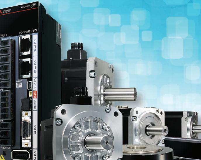

Setting up and confi guring a servo system can be painful. MELSERVO-J5 Servo motors and amplifi ers from Mitsubishi Electric create a pain-free experience that can:
Simplify or eliminate the commissioning process with unique tuning capabilities and software options.
Enhance system performance through predictive maintenance, functional safety over network, and 3.5 kHz speed frequency response.
Improve margins with fl exibile drive capacity and 10+ year design life.
Enjoy personalized support by phone, partner programs, and region, as well as extended warranties.

Maximize Efficiency and Performance Instantly

as “accurate” as the surface to which it’s mounted, so the mounting structure is an important factor. Mounting a “precision” accuracy linear guide to an unmachined base or an aluminum extrusion negates the guide’s travel accuracy performance.
Predictable, measurable factors that influence a system’s positioning and travel accuracy, such as screw lead deviation or profi led rail height, can be compensated to some extent through the feedback and control system. In systems with closed-loop, servo control, it can be more cost-effective to choose lower accuracy mechanical systems and use the servo system to improve accuracy through error mapping in the control.
The repeatability of a linear system is determined primarily by the drive mechanism — that is, the lead accuracy of a screw, the tooth pitch deviation and maximum stretch of a belt, or the backlash in a rack and pinion system.
The best way to improve repeatability is to remove play, or clearance, in the drive mechanism. Ballscrews are often specified with preload to eliminate backlash, and many leadscrew designs also offer zero backlash. Rack and pinion systems inherently have backlash between the gear rack and the pinion teeth, but dual pinion and split pinion designs remove this backlash.
If the system experiences significant temperature fluctuations, the expansion and contraction of components due to thermal effects can also reduce a system’s repeatability. Unlike positioning or travel accuracy, the repeatability of a system cannot be improved through feedback and control. The only way to improve the repeatability of a linear system is to use a drive that has higher repeatability.
Whether a designer or engineer should be more concerned with accuracy or repeatability depends on the type of application. In positioning applications such as those in pick and place or assembly operations, positional accuracy and repeatability are often the most critical factors. But in applications such as dispensing, cutting, or welding, where uniformity and accuracy of the process during travel is critical, travel accuracy should be the primary focus.
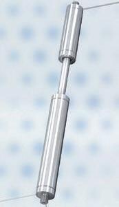
When an application requires pure thrust forces, the best type of linear actuator is often a rod-style actuator. Also called thrust actuators or (when a motor is integrated) simply electric actuators, these electromechanical devices excel at providing axial or thrust forces for pushing, pulling, or holding loads.
Although their function is straightforward, thrust actuators come in an extensive range of designs, sizes, and configurations.
The typical drive mechanisms for thrust actuators are ball, lead, or roller screws, and tubular linear motors. Drive mechanisms that aren’t common in these designs are belt and pulley or rack-andpinion systems. That’s because these other technologies don’t have sufficient thrust force and rigidity (in the case of belts) or a suitable form factor (in the case of rack-and-pinion sets) to make sense in thrust actuators.
Thrust actuators can also be driven by pneumatic or hydraulic cylinders, but electromechanical designs are more common than air or fluid technologies in motion control applications.
Thrust force is transmitted to the load by a rod that extends and retracts, guided by a plain bushing, from the actuator body. Typical thrust actuators don’t include linear guides, because their design is not inherent to carrying loads — only pushing, pulling, or holding them. If support or guiding of the load is required then rails, shafts, or tracks independent of the actuator are used.
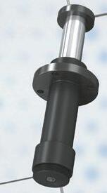
While most rod-style actuators include a housing to remain stationary and the thrust tube to extend and retract, some designs allow the tube to be fi xed and the housing to move. This is more common in linear-motor designs, but some screw-driven designs allow this configuration as well.
Because they often replace pneumatic or hydraulic versions, it’s common for electromechanical thrust actuators to be designed with outer dimensions and mounting options that follow standards, such as ISO and NFPA to
which pneumatic and hydraulic cylinders commonly adhere. Ball and leadscrew versions are good replacements for pneumatic technologies because they eliminate the need for compressors, fi lters, valves, and other air-handling equipment. When driven by large-diameter ballscrews or by roller screws, electromechanical thrust actuators have extremely high power density and provide a less complex solution than hydraulic actuators.
Electromechanical rod-style actuators are more likely than their traditional slider-type counterparts to be provided with an integrated motor and control hardware. In addition to reducing complexity for OEMs and end users, providing a full electromechanical solution in one package makes the switch from pneumatic or hydraulic technology to electromechanical technology less cumbersome. Integration options for thrust actuators range from low-voltage dc motors with limit switches for simple end-to-end positioning, to plug-and-play servo designs with integrated motor, drive, and controller.
Thrust force is transmitted to the load by a rod that extends and retracts, guided by a plain bushing, from the actuator body.
The housing of a thrust actuator is typically a fully-enclosed design that encapsulates the mechanical and electrical components. With a seal added to the thrust rod, it’s often possible for these actuators to achieve high IP ratings, making them suitable for applications where the actuator is exposed to fi ne particles, liquids, or washdown conditions. Most manufacturers also offer plating and coating options for the housing for corrosion resistance to myriad chemicals and environments.
Although there are no industry standards that defi ne linear actuators and linear stages, generally accepted terminology indicates that a linear actuator is typically constructed with an aluminum extrusion or base; or a linear stage is typically built
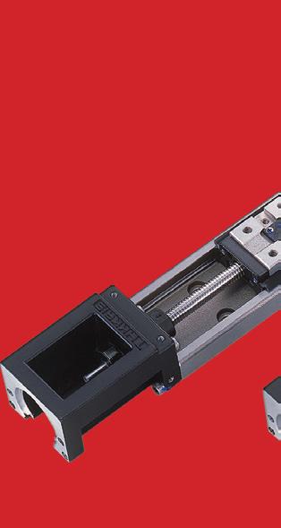
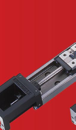
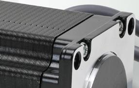
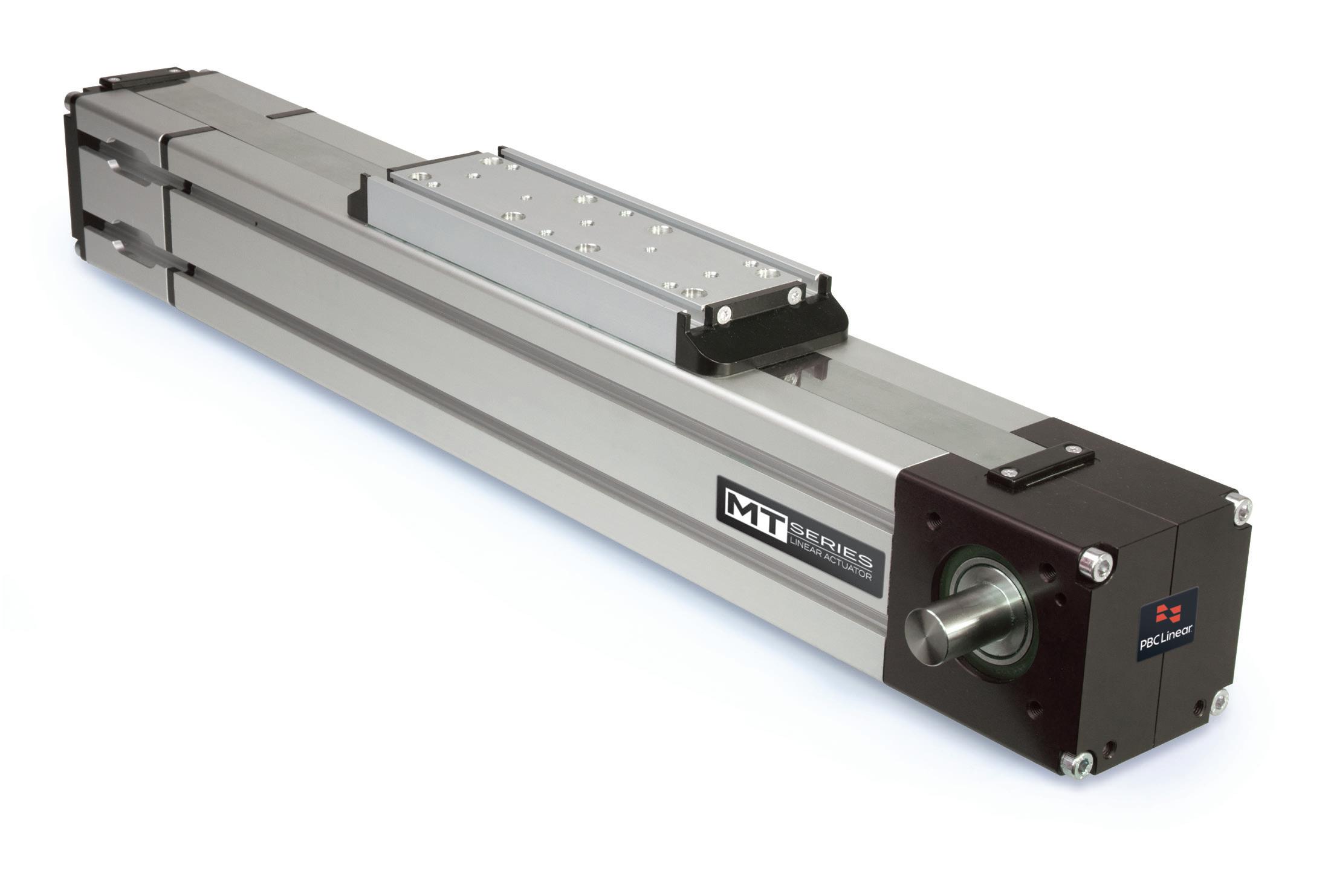
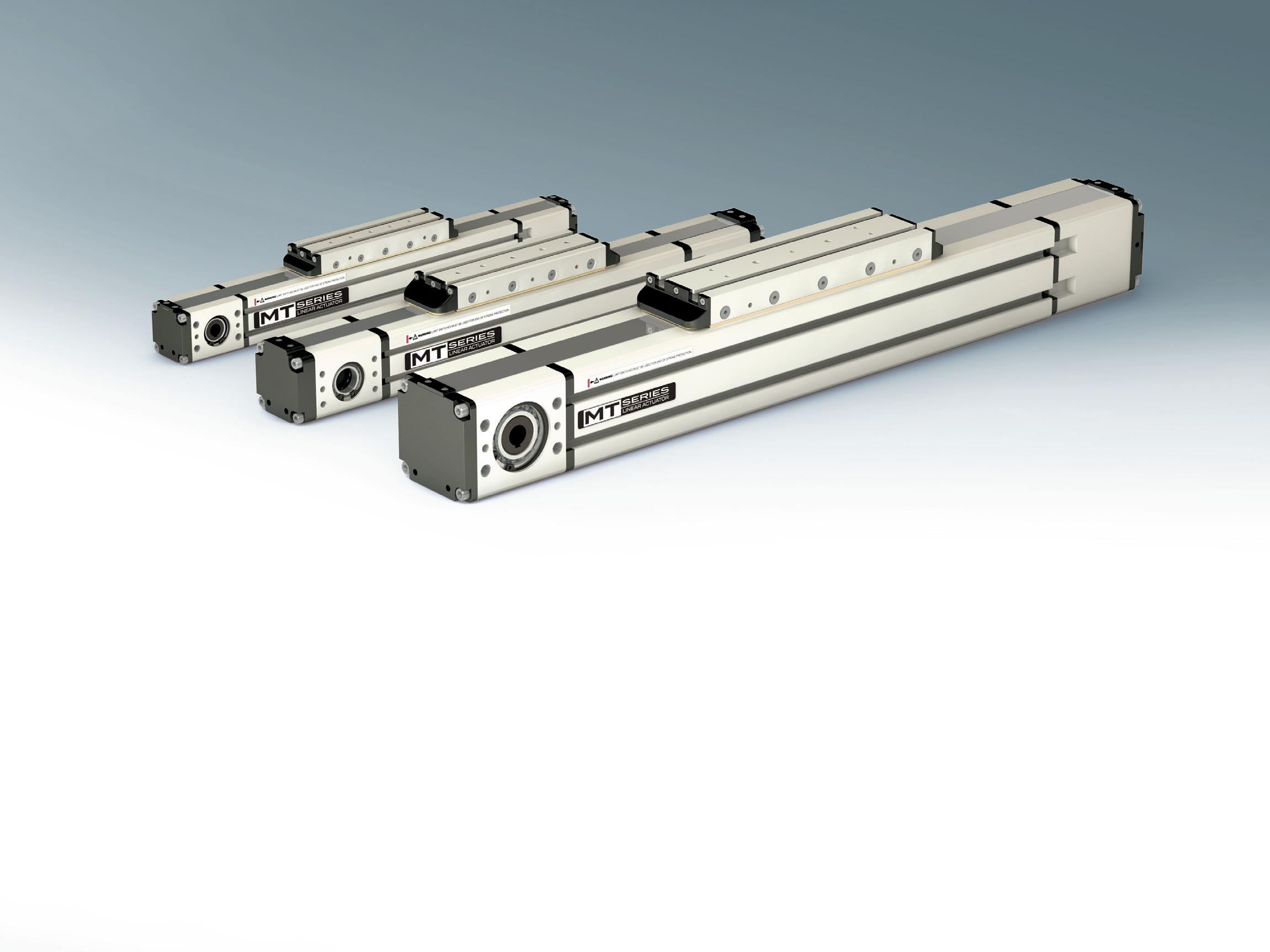
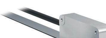
The MTB Series is a belt driven, profile rail linear actuator that has a number of sizes with some design configuration availability to meet high loads and stroke length.
MTBs are fully enclosed systems that perform at speeds up to 3000 mm per/second. With the addition of the MTB 105 linear actuator, the series now can move a static load of 7500 N and with a thrust capacity of 2750 N.
Applications:
Packaging and Assembly Automation
Cartesian Multi-axis Gantry Systems
Pick & Place Gantries
Automated Door Systems
Manufacturing Equipment Motion
MAX
MAX


VIBRATION CONTROL


SAFETY PRODUCTS


on a flat machined steel or granite base. This distinction implies that linear actuators can provide longer strokes and use a variety of drive mechanisms (belt, screw, rack and pinion) while stages generally have higher rigidity and use high-precision linear guides and drive mechanisms (typically a ballscrew or linear motor) for excellent travel and positioning accuracies.
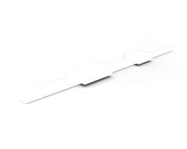
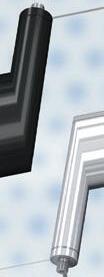
But one actuator design — the U-shaped linear actuator — defies these specifications ... using an extruded steel base to provide rigidity and travel accuracy specifications that rival some linear stages.
The use of a steel (rather than aluminum) profi le makes the U-shaped design extremely rigid and allows manufacturers to offer a linear actuator with the high travel and positioning accuracies typically found in more precise (and more expensive) linear stages.
The steel base can also be machined to provide a reference edge for precise alignment with other machine components ... or with other actuators in a multi-axis system.
With their very high rigidity, U-shaped linear actuators can be better suited than other designs to applications where the actuator is supported only on one end.
These include two and three-axis Cartesian systems, for example.
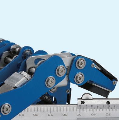
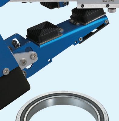
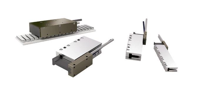
In the U-shaped actuator design, the linear guide system is integrated — and there is no guide rail. Instead, the raceways that would normally be found on the guide rail are ground into the inside of the base. The carriage or table is analogous to a linear bearing block turned inside-out, with the balls riding on the outside.
This leaves the center portion of the carriage available to accommodate the ballscrew nut. This construction principle makes the entire actuator extremely compact, with a width-to-height ratio of approximately 2:1.
For example, a U-shaped actuator with a width of 60 mm is only 33 mm high. The most common cross-sections (width x height) are 40 x 20 mm, 50 x 26 mm, 60 x 33 mm, and 86 x 46 mm … although
other sizes are offered as well.
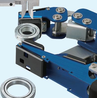
Despite their compact dimensions, U-shaped linear actuators have excellent load and moment capacities. This is because the raceways are spaced relatively far apart ... so the geometry of the carriage is like that of a bearing block much larger than the actuator could accommodate in its standard form.
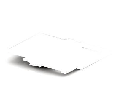
Some manufacturers offer U-shaped linear actuators made from extruded aluminum profi les, with steel inserts for the linear guide raceways.
Aluminum versions lack the rigidity of steel designs, but they offer a very compact profi le. In addition, they are often dimensionally interchangeable with steel versions where an application might benefit from a lower-cost option.
The use of a steel (rather than aluminum) profi le makes the U-shaped design extremely rigid and allows manufacturers to offer a linear actuator with the high travel and positioning accuracies typically found in more precise (and more expensive) linear stages.
While steel versions of U-shaped linear actuators use ballscrew drives almost exclusively, aluminum designs are more likely to be offered with both ballscrew and leadscrew drive options.
Originally developed for highprecision applications such as semiconductor wafer handling and medical diagnostic dispensing — for which space constraints don’t allow a typical linear stage — U-shaped linear actuators are now used in a wide variety of industries and applications. These include plasma welding, automated assembly, and optical inspection.
One of the driving factors behind the widespread adoption of U-shaped actuators is that they are the only linear actuator design with dimensional interchangeability between manufacturers.
However, due to differing guideway and ballscrew designs, technical specifications (such as load capacity, speed, or rigidity) can vary between manufacturers and product lines — even for products with the same cross-sectional size and mounting dimensions. •
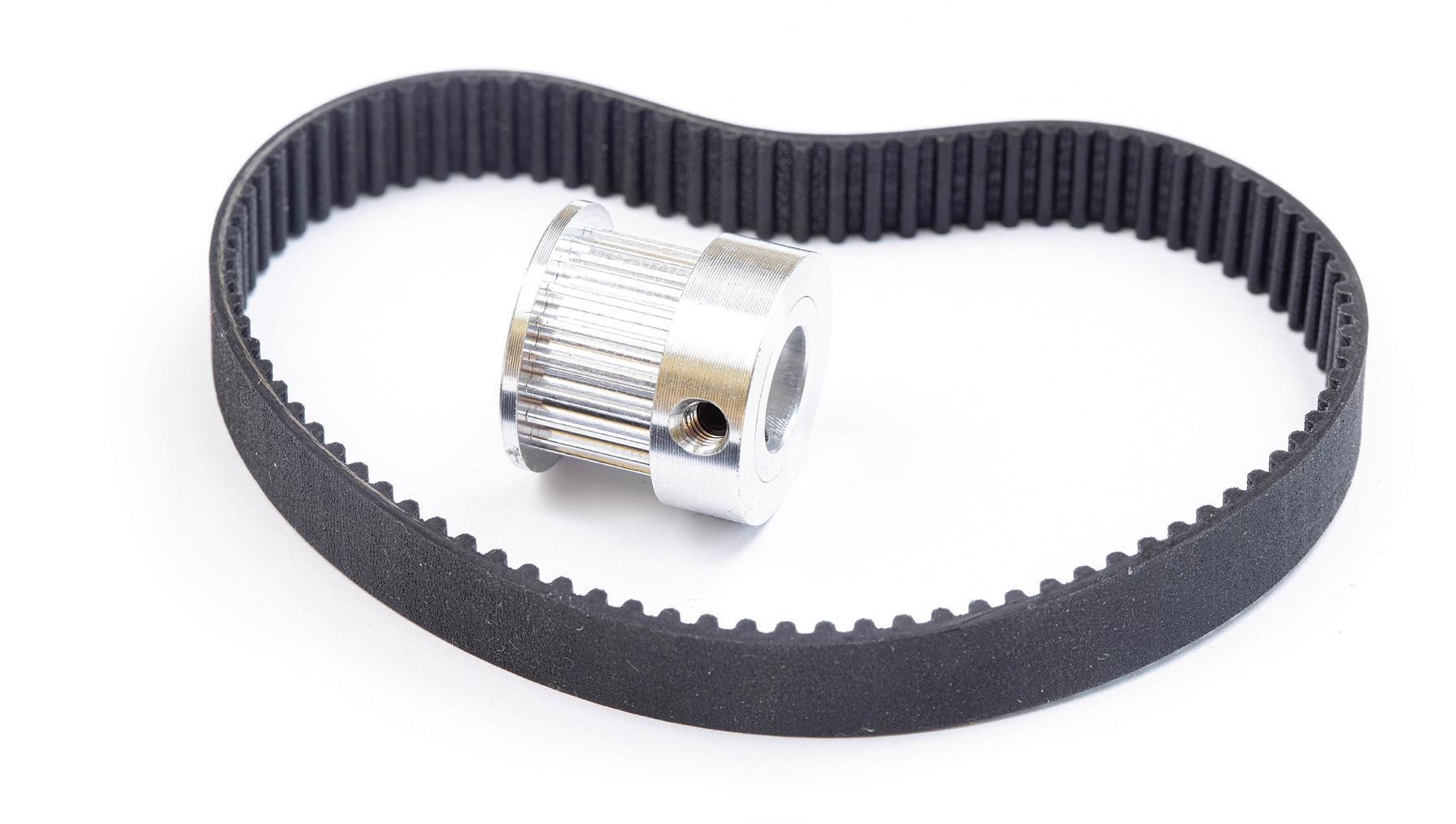
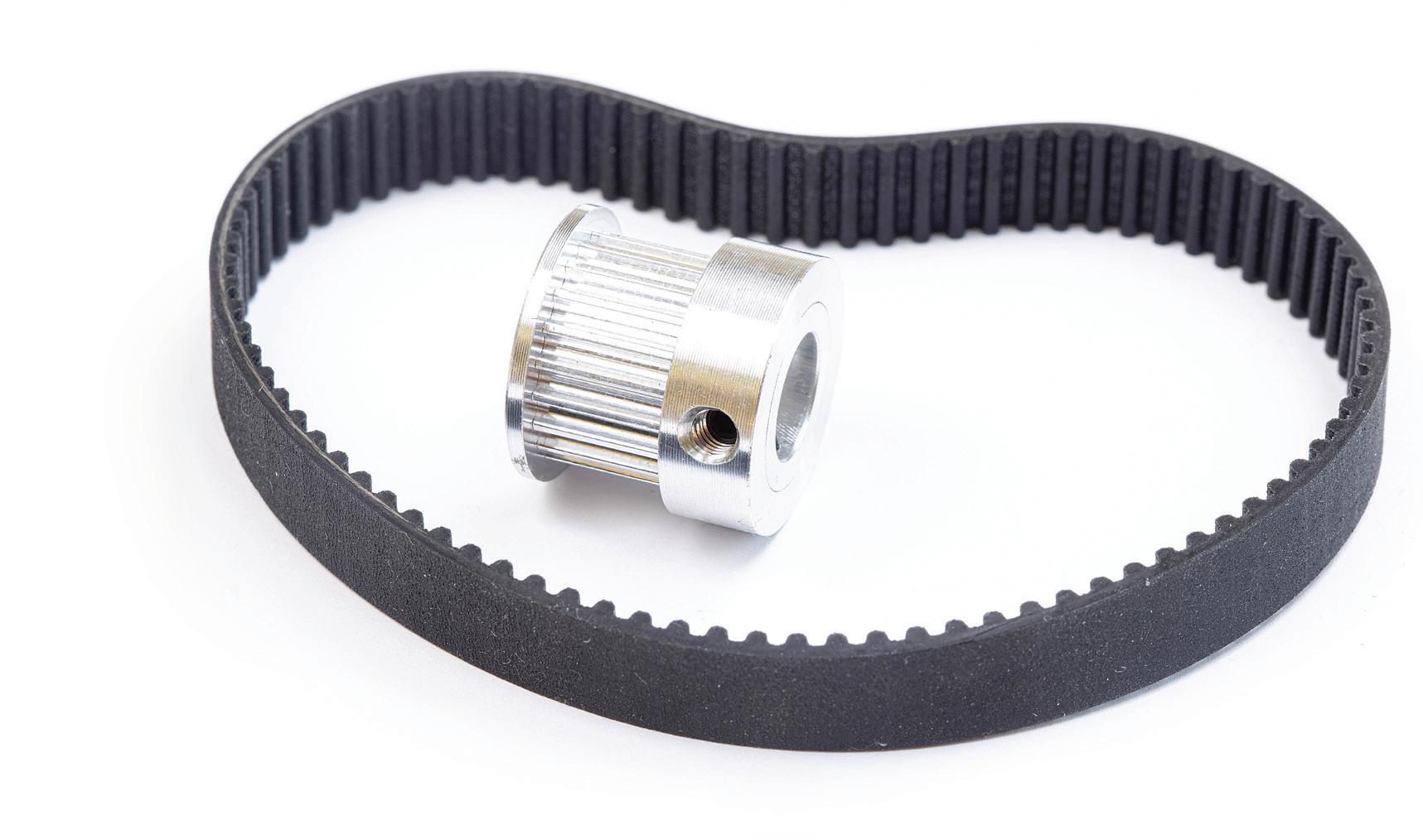
A common method of power transmission is the belt drive system. Industrial belt drives typically consist of belts that wrap around drive pulleys, that are in turn driven by electric motors.
Design engineers use belt drives because they require little if any maintenance, they’re less expensive than chain drives, and they are quiet and efficient, up to 95% or more. They also offer longer stroke lengths and faster speed capabilities than screw driven designs, with less inertia and better resistance to contamination than rack and pinion drives. And although linear motors boast better positioning accuracy than belts, the priceperformance ratio of a belt-driven actuator is tough to beat. As for the belt material, the tensile members of the belts used today — cords embedded into the belt rubber that carry the majority of the belt load—are stronger than ever. They’re made of a number of materials including polyester, aramid, fiberglass or carbon fiber.
Belt-driven actuators have been used
for decades in applications ranging from high-speed transport to basic positioning. The most common designs use an aluminum extrusion housing for protection against contamination, or an open-frame design for lower weight and reduced cost.
Despite their inherent versatility, belt drive actuators continue to evolve, with manufacturers introducing new designs to reduce size, weight, and cost — making them better able to compete with leadscrew actuators.
To achieve this, recirculating ball or wheel-based guides are replaced with plain bearing guides made of plastic or composite, and carriages are made of aluminum or even thermoplastic. Although plain bearings have lower load capacities than steel ball or rollerbased linear bearings, they do offer a benefit in harsh environments by withstanding debris and chemicals better than their steel counterparts. And because these lower-cost versions aren’t meant for high-accuracy positioning, non-reinforced neoprene belts are often suitable.
Manufacturers typically describe belts and pulleys with five main geometries. Pitch diameter is the drive pulley’s diameter. Center distance is the distance between the two pulleys’ centers. Minimum wrap angle is a measure of how much the belt wraps around the smallest pulley. Belt length is how long the belt would be if cut and laid flat. Finally, in the case of toothed belts (also called synchronous belts) the pitch is the number of teeth per some length — for instance, a 3-mm pitch means that the belt has one tooth every 3 mm.
Recently there has been a convergence of specialty belt drive systems in mass-produced consumer and light industrial tools with the standard belt drives integrated into various machine designs. That’s because options have proliferated for belts with flat and round profiles as well as those with various V-shaped profiles and toothed belts for synchronous operation.


Synchronous belts can transmit high torque without the potential for slip, due to positive engagement between the teeth of the belt and the grooves of the pulley. But the performance of synchronous belt drive systems can be affected by installation errors, unexpected application conditions, or the use of components that aren’t suitable for the operating requirements. Here are six ways that synchronous belts can fail and their most common causes.
Flanged pulleys provide tracking for synchronous belts by resisting the lateral forces from the belt as it tries to move from side to side on the pulley. But in some cases, the belt can ride along the flange and exert significant force on it, resulting in wear on the edge of the belt. Common causes of edge wear are parallel misalignment, using a belt that is too wide for the selected pulley, or using pulleys that are damaged or have a rough surface finish.
Belt cracking usually occurs parallel to the teeth, in the areas between the teeth called land areas. Cracking is often associated with temperature issues – either a
temperature that is too low at startup or too high during operation, causing the material to harden and crack due to bending. Other causes of belt cracking are a skewed pulley assembly or exposure to chemicals.
This type of failure is typically due to crimping or severe shock loads to the belt. Crimping often produces a tear straight across the belt and can be caused by mishandling of the belt, inadequate tension, a pulley diameter that is too small, or debris in drive system. Shock loads often result in an angled tear across the belt and can be accompanied by tooth shear.
Tooth wear is a normal result of the positive engagement between the belt and pulley and is mitigated by belt materials that are wear-resistant. However, excessive wear can result from either too much or too little tension, misalignment, excessive loading, debris in the drive system, a damaged pulley, or a pulley that is out of spec or does not have sufficient hardness. Under normal operating conditions, tooth wear generally does not affect the service life of the belt.
Tooth shear is a catastrophic failure that can be caused by shock loads or


misalignment. It can also be a result of insufficient tension, which causes a condition known as self-tensioning — which in turn makes the belt teeth ride out of the pulley. When this happens, the load is no longer carried at the roots of the teeth, but rather further down the tooth flanks. This causes the teeth to bend and rotate, which can cause them to tear at their base and separate from the belt.
Ratcheting is a condition in which belts jump or skip teeth on the pulley. The primary cause of ratcheting is insufficient belt tension. One of the benefits of synchronous belts, when compared to V-belts, is that once the tension is properly set, they do not require re-tensioning.
While synchronous belt failures can occur in many forms, pulleys generally fail in one of two ways: tooth wear or flange failure.
Abnormal or excessive pulley tooth wear is typically due to use in an abrasive environment, although pulley misalignment, excessive loading, and improper tension can also be causes. Pulley flange failure is most often a result of angular or parallel pulley misalignment. •
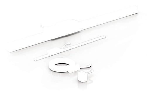
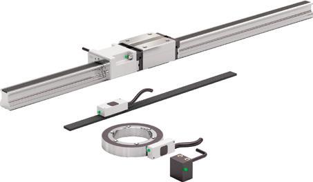
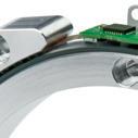
Position, angle and speed measurement
Contactless, no wear and maintenance-free
High positioning accuracy and mounting tolerances
Linear and rotary solutions


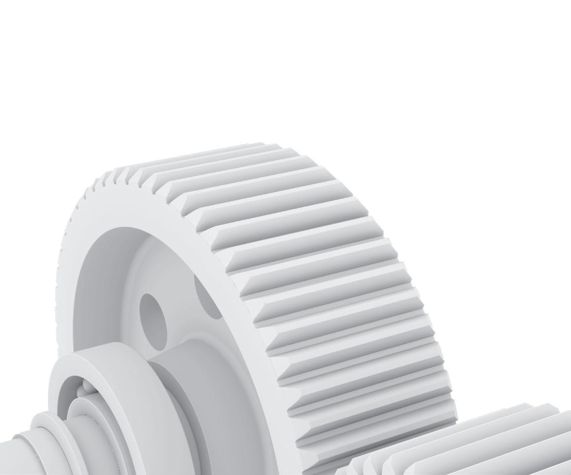
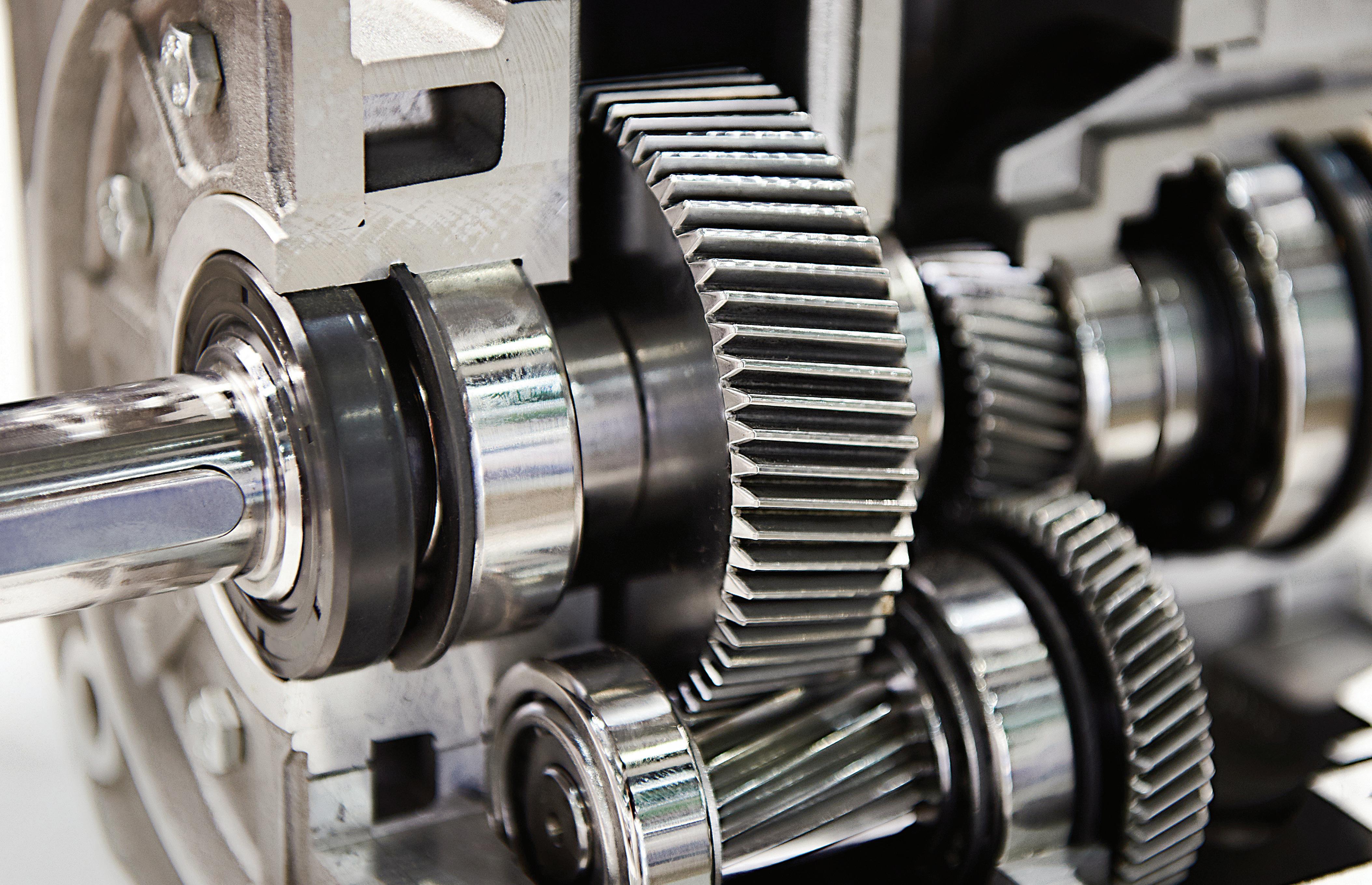
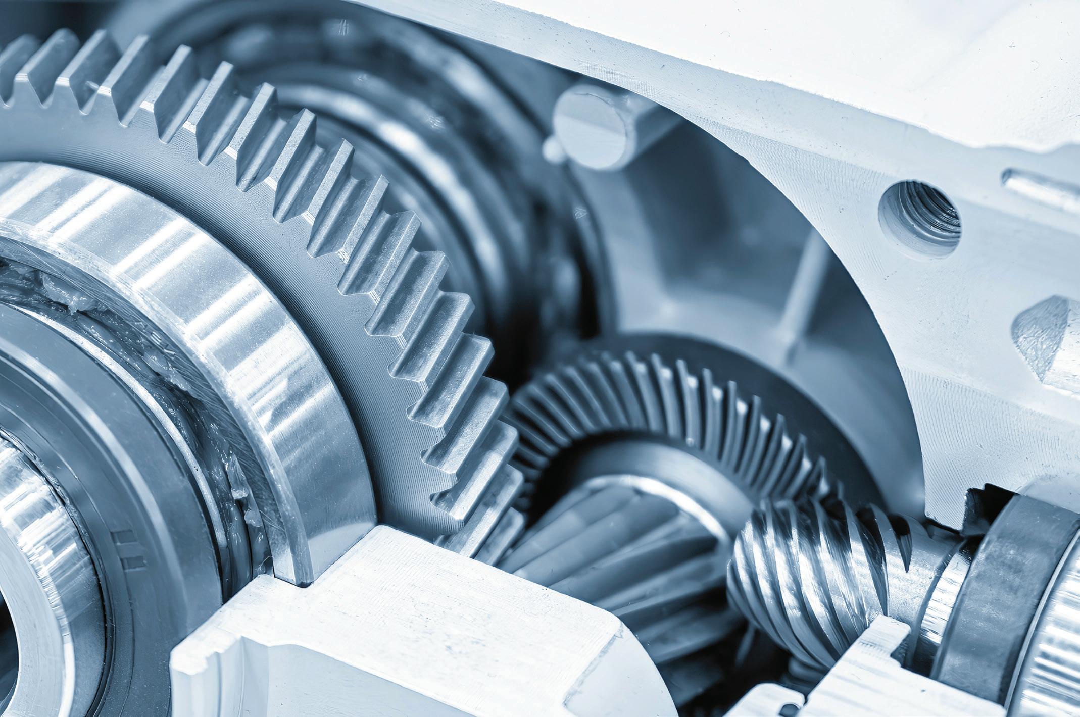
With helical gearing, multiple teeth are always in mesh, so there is less load on each individual tooth. This results in a smoother transition of forces from one tooth to the next … for reduced vibrations, shock loads, and wear.
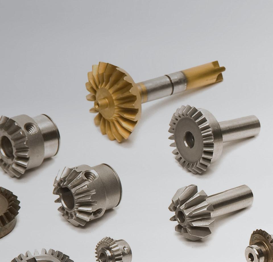
Gears use globally has seen a shift with increased adoption of electric vehicles. This industry has driven new innovation that has advanced gear technologies that are more accurate, quiet-running, and efficient than in the past. In fact, digitization is also leveraging additive manufacturing, DX connectivity, and roboticized processes for advanced manufacturing to continually increase quality standards. That in turn has prompted the manufacture of gears having better finishes than what was possible even a few years ago.
These developments have even advanced tried-and-true spur gears — especially with new applications for profi le modifications, fi nite-element analysis, and direct metal laser sintering. Spur gears are a type of cylindrical gearing with shafts that are parallel and coplanar ... and teeth that are straight and oriented parallel to the shafts. They’re arguably the simplest and most common type of gear — easy to manufacture and suitable for a wide range of applications.
The teeth of a spur gear have an involute profi le and mesh one tooth at a time. The involute form means that spur gears only produce radial forces (no axial forces), but the method of tooth meshing causes high stress on
the gear teeth and high noise production. Because of this, spur gears are typically used for lower speed applications, although they can be used at almost any speed.
Involute gear teeth have a profi le that is the involute of a circle. So as two involute gears mesh, they contact at a single point where the involutes meet. This point moves along the tooth surfaces as the gears rotate ... and the line of force (known as the line of action) is tangent to the two base circles. In this way, the gears adhere to the fundamental law of gearing — that the ratio of meshing gears’ angular velocities must remain constant throughout the mesh.
Spur gears can be made from metals such as steel or brass or from plastics such as nylon or polycarbonate. Plastic gears are quiet but at the expense of strength and loading capability. Unlike other gear types, spur gears don’t experience high losses due to slippage, so they generally have high transmission efficiency. Multiple spur gears can work in series (referred to
as a gear train) to achieve large reduction ratios.
The two types of spur gears are external and internal. External gears have teeth that are cut on the outside surface of the cylinder. Two external gears mesh together and rotate in opposite directions. In contrast, internal gears have teeth cut on the inside surface of the cylinder. An external gear sits inside the internal gear, and the gears rotate in the same direction. Because the shafts are positioned closer together, internal gear assemblies are more compact than external gear assemblies. Internal gears are primarily used for planetary gear drives.
Spur gears are generally best for applications needing moderate speed reduction and torque multiplication — such as ball mills and crushing equipment. High-speed applications that use spur gears (despite their high noise levels) include consumer appliances such as washing machines and blenders. Though noise limits the use of spur gears in passenger automobiles, they’re common in
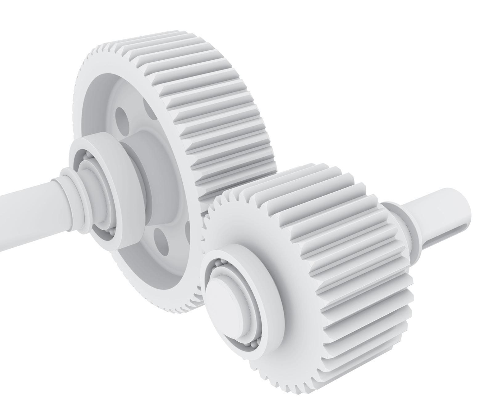
aircraft engines, trains, and even bicycles. Now consider another common gear type — that of helical gears. Spur gears are simple and inexpensive to manufacture, but helical gears offer some important advantages over spur gears. The teeth of a helical gear are set at an angle (relative to axis of the gear) and take the shape of a helix. This allows the teeth to mesh gradually, starting as point contact and developing into line contact as engagement progresses. One of the most noticeable benefits of helical gears over spur gears is less noise, especially at medium- to high-speeds. Also, with helical gears, multiple teeth are always in mesh, which means less load on each individual tooth. This results in a smoother transition of forces from one tooth to the next, so that vibrations, shock loads, and wear are reduced.
But the inclined angle of the teeth also causes sliding contact between the teeth, which produces axial forces and heat, decreasing efficiency. These axial forces play a significant role in bearing selection for helical gears. Because the bearings must withstand both radial and axial forces, helical gears require thrust or roller bearings, which are typically larger (and more expensive) than the simple bearings used with spur gears.
The axial forces vary in proportion to the magnitude of the tangent of the helix angle. Although larger helix angles provide higher speed and smoother motion, the helix angle is typically limited to 45° due to the production of axial forces.
The axial loads produced by helical gears can be countered by using double helical or herringbone gears. These arrangements have the appearance of two helical gears with opposite hands mounted back-to-back, although in reality they are machined from the same gear. Note that the difference between the two designs is that double helical gears have a groove in the middle, between the teeth, whereas herringbone gears do not.
This arrangement cancels out the axial forces on each set of teeth, so larger helix angles can be used. It also eliminates the need for thrust bearings.
Besides smoother motion, higher speed capability, and less noise, another


CGI Motion standard products are designed with customization in mind. Our team of experts will work with you on selecting the optimal base product and craft a unique solution to help di erentiate your product or application. So when you think customization, think standard CGI assemblies.

Connect with us today to explore what CGI Motion can do for you.


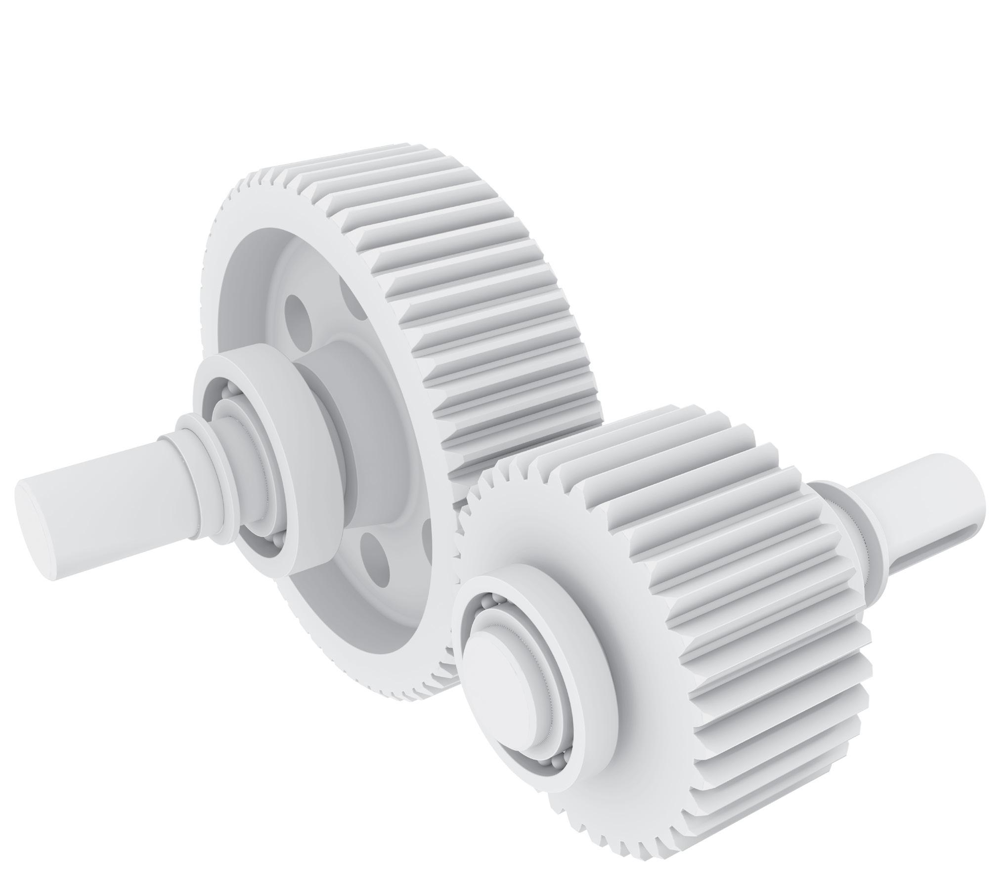
Spur gears are simple and inexpensive to manufacture, but helical gears offer some important advantages over spur gears.
The straight teeth of spur gears are easier to manufacture, so are cost effective.

FREQUENCY (Hz)
advantage that helical gears provide over spur gears is the ability to be used with either parallel or non-parallel (crossed) shafts. Helical gears with parallel shafts require the same helix angle but opposite hands —in other words, right-handed teeth versus left-handed teeth.
When crossed-axis helical gears are used, they can be of either the same or opposite hands. If the gears have the same hands, the sum of the helix angles should equal the angle between the shafts. The most common example of this are crossed helical gears with perpendicular (90°) shafts. Both gears have the same hand, and 90° is the sum of their helix angles. For configurations with opposite hands, the difference between helix angles should equal the angle between the shafts.
Crossed helical gears provide flexibility in design, but the contact between teeth is closer to point contact than line contact. That means they have lower force capabilities than parallel-shaft designs — so are not the most suitable for heavy loads or axes needing very dramatic
The angled teeth of helical gears are longer for higher load capacity and quieter engagement.

FREQUENCY (Hz)
speed reductions. Helical gears are often the default choice in applications that are suitable for spur gears but have non-parallel shafts. They are also used in applications that require high speeds or high loading. Plus regardless of the load or speed, they generally provide smoother, quieter operation than spur gears.
To review, the axial loads produced by helical gears can be countered by using double helical or herringbone gears. Besides smoother motion, higher speed capability, and less noise, another advantage that helical gears provide over spur gears is the ability to be used with either parallel or non-parallel (crossed) shafts. Helical gears with parallel shafts require the same helix angle, but opposite hands (i.e. right-handed teeth vs. lefthanded teeth). When crossed helical gears are used, they can be of either the same or opposite hands. If the gears have the same hands, the sum of the helix angles should equal the angle between the shafts. Crossed helical gears provide flexibility in
design, but the contact between teeth is closer to point contact than line contact, so they have lower force capabilities than parallel shaft designs.
In addition, helical gears are often the default choice in applications that are suitable for spur gears but have nonparallel shafts. They are also used in applications that require high speeds or high loading.
Worm gears are found in industrial applications, heavy equipment, and even consumer applications. The efficiency of a worm gear varies based on the ratio and manufacturing methods.
Worm gears are constructed of a worm and a gear (sometimes called the worm wheel) with non-parallel and nonintersecting shafts oriented 90° to each other. The worm is analogous to a screw with a V-type thread ... and the gear is analogous to a spur gear. The worm is typically the driving component with the worm’s thread advancing the teeth of the gear.
Like a ball screw, the worm in a worm

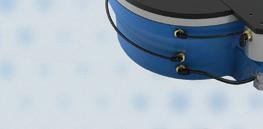
The SHA-IDT Series is a family of compact actuators that deliver high torque with exceptional accuracy and repeatability. These hollow shaft servo actuators feature Harmonic Drive servomotor, a brake, two magnetic absolute encoders and an integrated servo drive with CANopen communication. This revolutionary product eliminates the need for an external drive and greatly simplifies cabling yet delivers high-positional accuracy and torsional stiffness in a compact housing.
• Actuator + Integrated Servo Drive utilizing CANopen® communication
• 48 VDC nominal supply voltage
• A single cable with only 4 conductors is needed: CANH, CANL, +48VDC, 0VDC
• Zero Backlash

• Panel Mount Connectors with radial and axial options
• Dual Absolute Encoders
• Output Encoder: 16bit (65,536 cpr) resolution
• Input Encoder: 17bit (131,072 cpr) resolution
• Control Modes include: Torque, Velocity, and Position Control, CSP, CSV, CST
gear may have a single start or multiple starts — meaning that there are multiple threads or helices on the worm. For a single-start worm, each full 360° turn of the worm advances the gear by one tooth. So a gear with 24 teeth will provide a gear reduction of 24:1.
For a multi-start worm, the gear reduction equals the number of teeth on the gear, divided by the number of starts on the worm. This is different from most other types of gears, for which the gear reduction is a function of the diameters of the two components.
The meshing of the worm and the gear is a mixture of sliding and rolling actions, but sliding contact dominates at high reduction ratios. To minimize friction (and therefore heat) the worm and gear are made of dissimilar metals — for example, the worm may be made of hardened steel and the gear made of bronze or aluminum.
Although the sliding contact reduces efficiency, it provides very quiet
operation. (The use of dissimilar metals for the worm and gear also contributes to quiet operation.) This makes worm gears suitable for use where noise should be minimized, such as in elevators. In addition, the use of a softer material for the gear means that it can absorb shock loads, like those experienced in heavy equipment or crushing machines.
The primary benefit of worm gears is their ability to provide high reduction ratios and correspondingly high torque multiplication. They can also be used as speed reducers in low- to medium-speed applications. Plus because their reduction ratio is based on the number of gear teeth alone, they are more compact than other types of gears. Like fi ne-pitch lead screws, worm gears are typically self-locking, which makes them suitable for hoisting and lifting applications.
In a worm gear assembly, the worm is typically the driving component. Selflocking means that the gear cannot drive
the worm. In other words, back driving is not possible.
Self-locking can occur when the assembly is in either a static or a dynamic state, although it is more common when the worm gear is static – in other words not moving. In theory, as long as the coefficient of friction between the gear and the worm is larger than the tangent of the worm’s lead angle, the worm gear is considered self-locking and will not back drive. The static coefficient of friction generally depends on the materials of the two components and any lubrication between them. But in real-world use, other factors, such as the condition of the surfaces (ground surfaces introduce less friction than rough surfaces) or the presence of external vibrations, can lower the static coefficient of friction.
Dynamic friction is lower than static friction, and correspondingly, dynamic self-locking is less likely to occur than static self-locking for a worm gear with the
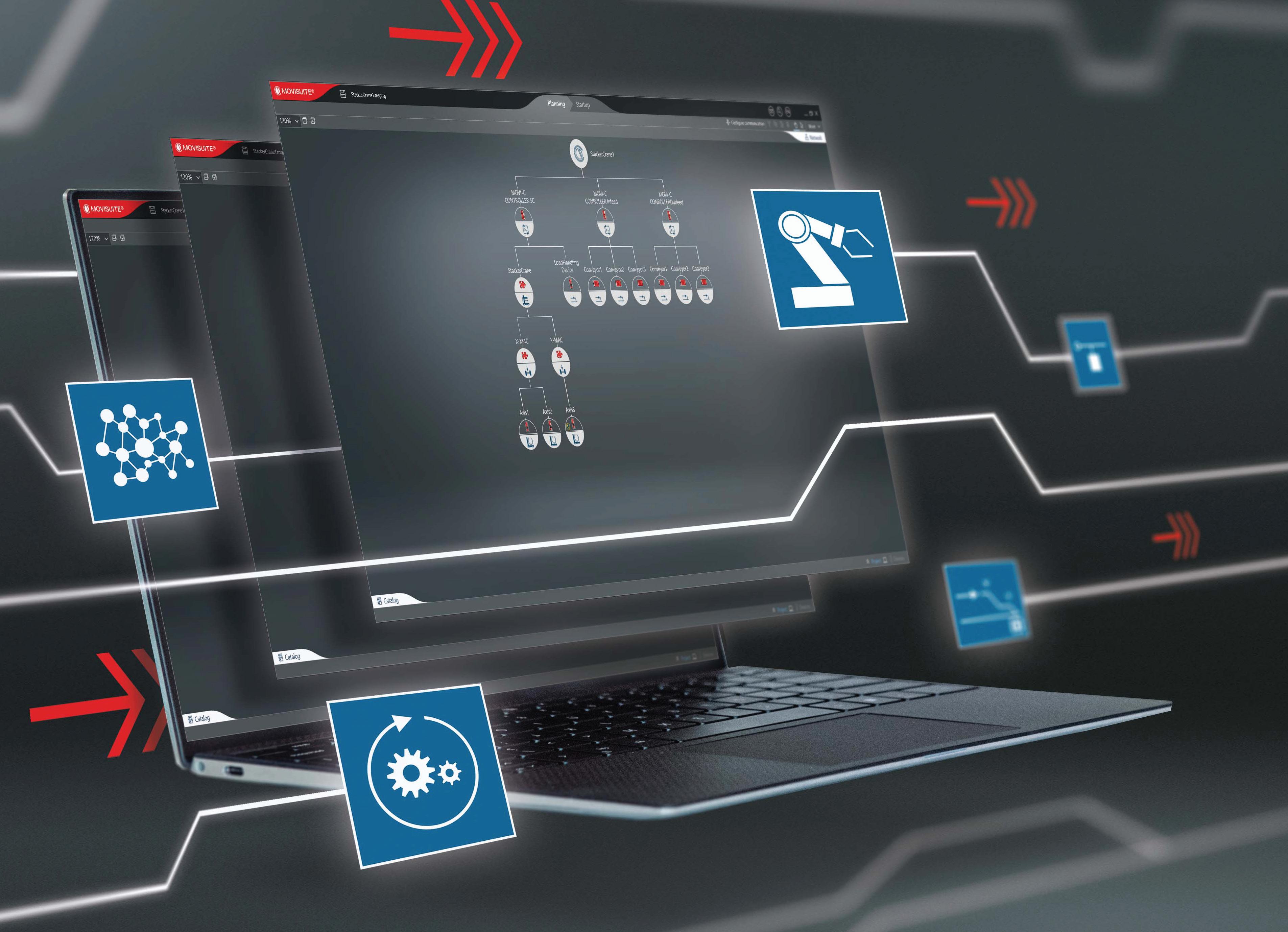
Pre-configured software modules for motion control
Would you rather enter parameters, or code? MOVIKIT ready-to-use automation modules are pre-configured software elements for many common motion control tasks ranging from simple speed control and positioning to complex multi-axis sequences. These intuitive, user-friendly modules are hardware independent, and can save commissioning time and costs. Simply enter paramters, and GO!

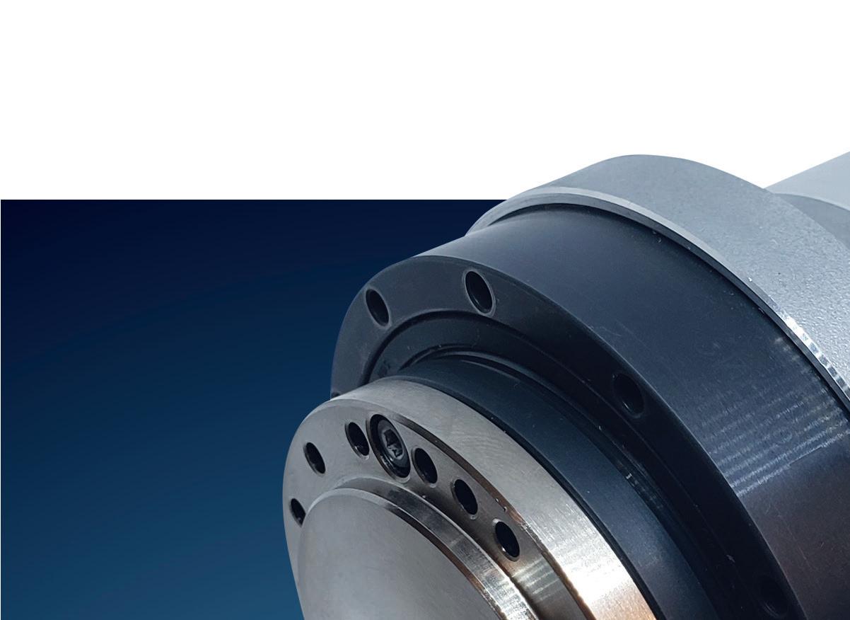
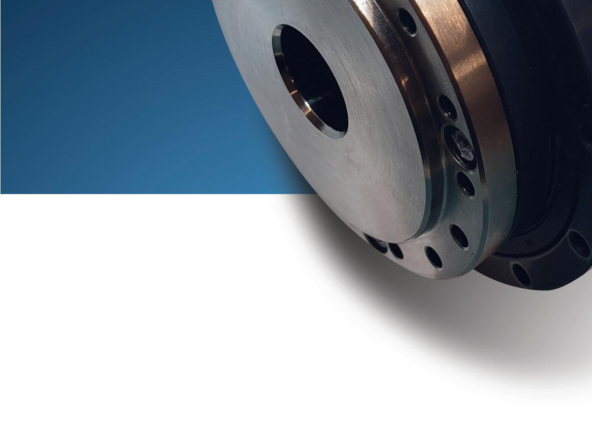
Strain-wave gearing is indispensable in robotics applications.

same lead angle and operating conditions. In addition to the considerations mentioned above for the static coefficient of friction, the coefficient of dynamic friction is also affected by the worm gear’s rotational speed and the lubrication’s behavior under dynamic conditions.
Another way to state the condition for self-locking is that the friction angle
between the worm and the gear must be larger than the worm’s lead angle. The static friction angle is the angle at which relative motion between two components (such as a block and a wedge) just begins to occur under otherwise static conditions. The dynamic friction angle is the angle that causes the motion between the two objects to cease.
The static coefficient of friction between a steel worm and a bronze gear is approximately 0.15, which gives a friction angle of approximately 8 to 9°: arctan(0.15) = 8.5°. The dynamic coefficient of friction depends on the speed of the worm gear. It can range from 0.08 at slow speeds –giving a friction angle of 4.6° to less than 0.02 at high speeds giving a friction angle of approximately 1 degree.
Self-locking, or the prevention of backdriving, is useful in applications that require lifting and/or holding loads. But the American Gear Manufacturers Association (AGMA) recommends that a brake should be used to ensure that a worm gear will not back drive, rather than relying on the worm gear’s theoretical ability to self-lock.
Now let us consider high-precision gear options. Many of today’s precision applications necessitate gears capable of dramatic speed reductions, power densities, and transmission accuracies. Leading choices in these designs include trochoidal and cycloidal gearing as well as gearsets relying on wave-inducing subcomponents having an elliptical or Reuleaux or other polygonal shape.
Recall from geometry that trochoidal and cycloidal gearing includes elements that rotate and trace curves around some other element. More specifically, cycloids traced by a point on a rolling element’s circumference include epicycloids (for which the element rolls along the outside of a sun gear or other reference component) and hypocycloids for which the element rolls within a ring or other reference component. In contrast, trochoids (and their subtypes) are traced not by a point on the rolling element’s circumference but rather some point within or without. One particularly common subtype of epicyclic gearing is planetary gearing. Here we’ll review other variations that are increasingly common in high-end machine tool, aerospace, material handling, and robotic applications requiring precision servo motion.
Consider the latter — in a robotic joint employing a motor (running at a few thousand rpm) fitted with gearing for output speeds to 100 times slower. Gearing in such designs also serves to
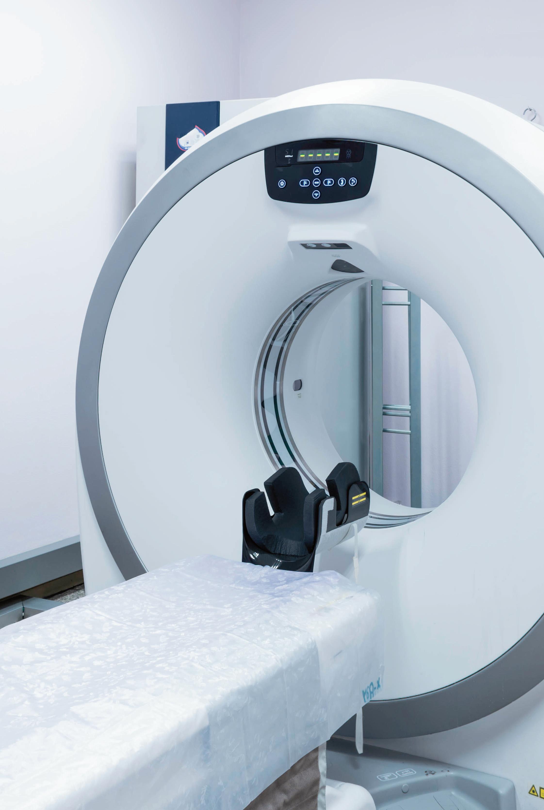
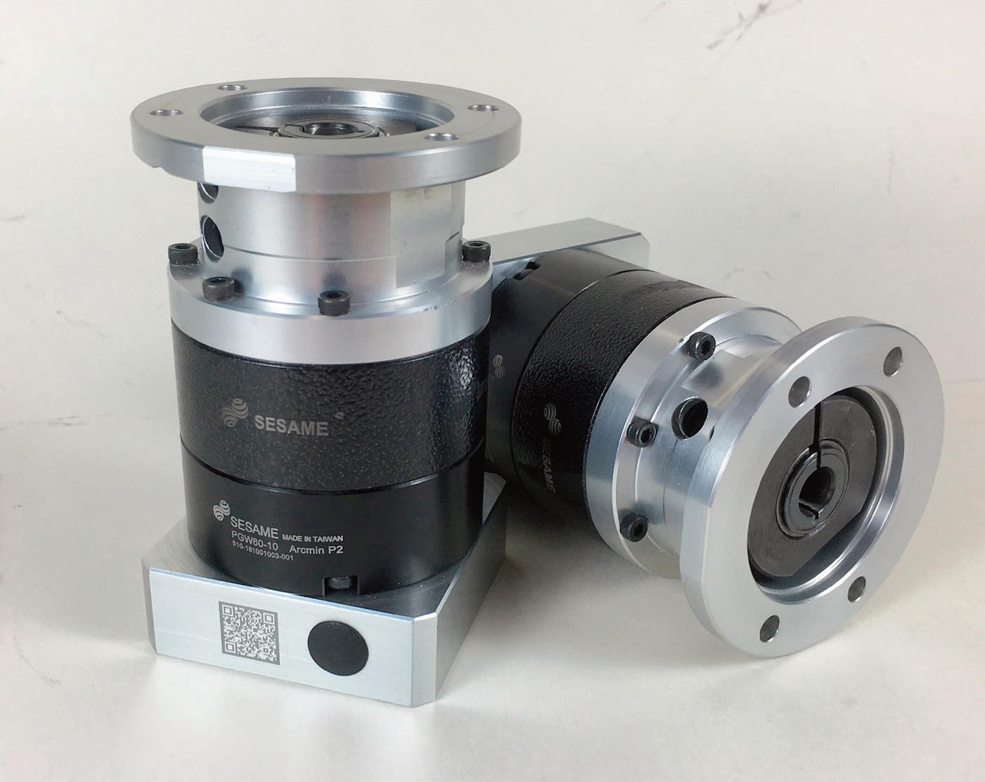
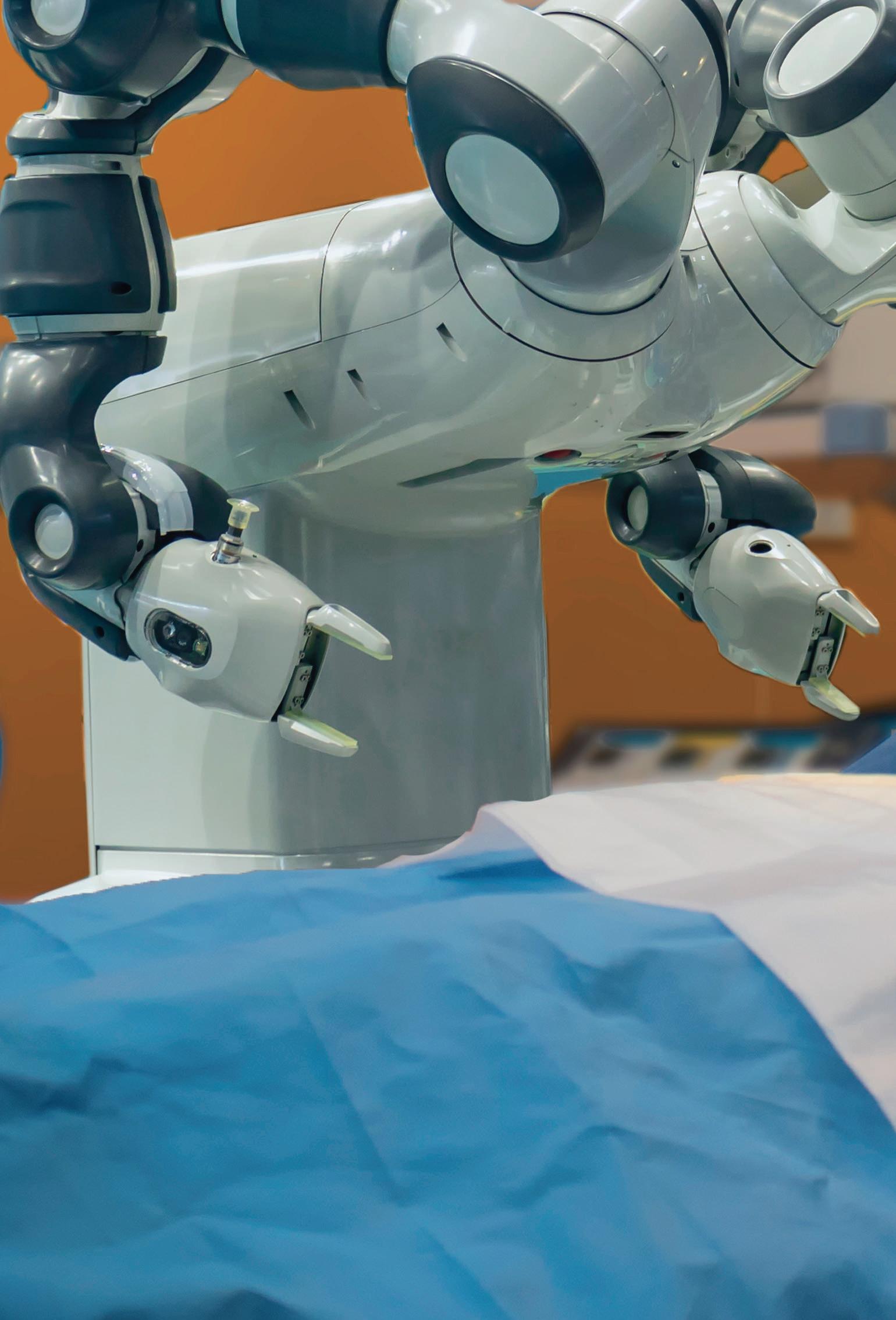
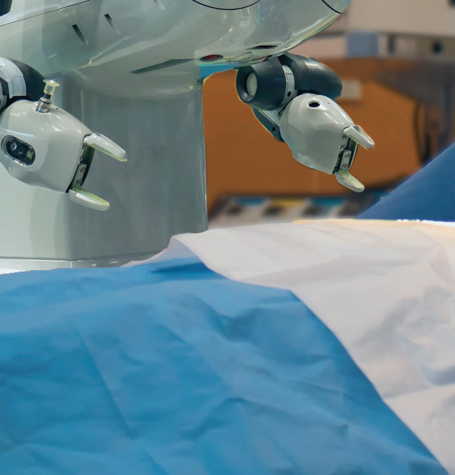


boost acceleration torque for top power density — a priority design objective for SCARAs and collaborative robotics for which the total assembly is essentially a cantilevered mass.
Recall that conventional gearing used in such designs (including some planetary gearsets) usually exhibit a very small amount backlash. This is often limited to only a few arc-min. (100ths of a degree) and serves to accommodate lubrication and thermal expansion. However, this backlash can in some cases degrade system accuracy by unacceptable amounts. So let’s take a look at other gear options that avoid the issue.
Strain-wave gearing uses the metal elasticity (deflection) of a gear to reduce speed. Key benefits of strain-wave gearing include zero backlash and high power density and positional accuracy.
A strain-wave gearset consists of three components: wave generator, flexspline, and circular spline. The wave generator is an assembly of a bearing
and a steel disc with an elliptical shape machined to precise specifications. A specialty ball bearing fits around this disc and conforms to the elliptical shape. Most designs attach the wave generator to a servomotor — to serve as the motion input.
The flexspline is a thin-walled steel cup. These cup walls are radially compliant but remain torsionally stiff — because the cup has a large diameter. Manufacturers machine the gear teeth into the outer surface near the open end of the cup ... near what one might call the brim.
The flexspline usually serves as the output.
The cup has a rigid boss at one end to provide a rugged mounting surface. The wave generator is inside the flexspline so the bearing is at the same axial location as the flexspline teeth. The flexspline wall near the brim of the cup conforms to the same elliptical shape of the bearing. This conforms the teeth on the outer surface of the flexspline to the elliptical shape. That way, the flexspline effectively has an
elliptical gear-pitch diameter on its outer surface.
The circular spline is a rigid circular steel ring with teeth on the inside diameter. It is usually attached to the housing and does not rotate. Its teeth mesh with those of the flexspline. The teeth of the flexspline engage the teeth of the circular spline along the major (long) axis of the ellipse. So there are two areas of meshing made by the ellipse inscribed concentrically within the ring. Roughly 30% of the teeth are engaged at all times — in contrast with six or so teeth engaged at any time for an equivalent planetarygear set, and one or two teeth for an equivalent spur-gear set.
Recall that backlash is the difference between the space to accommodate the teeth and the tooth width ... and this difference is zero in strain-wave gearing. Elastic radial deformation of the strain-wave flexpline (preloaded by the manufacturer against those of the circular spline at the major axis) acts like a very stiff spring to compensate for space between the teeth that would otherwise cause backlash. Preload is set to keep stresses well below the material’s endurance limit.
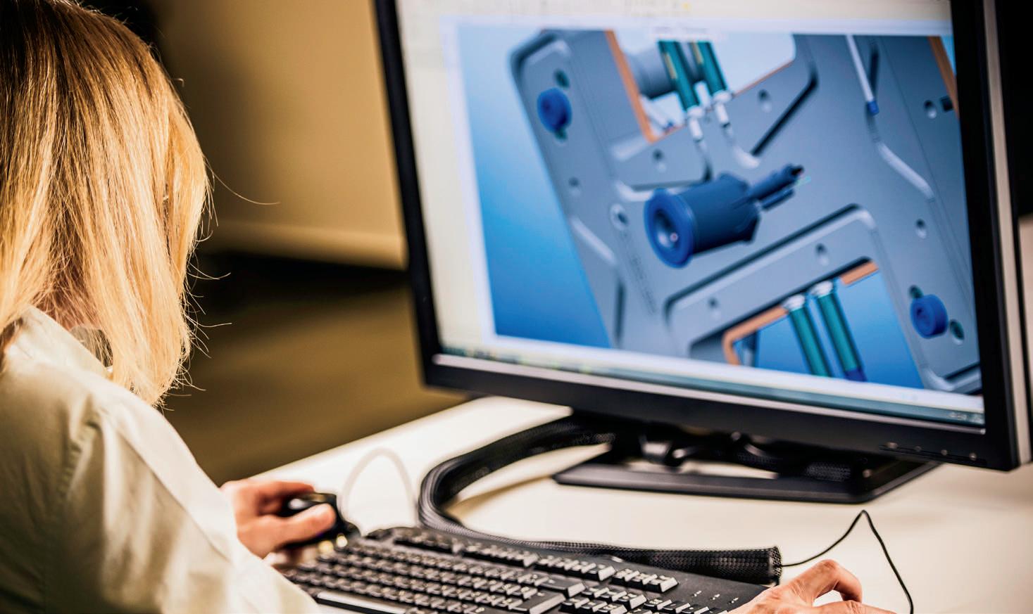
The pressure angle of the gear teeth transforms the output torque’s tangential force into a radial force acting on the wave-generator bearing. The flexspline and circular spline teeth engage near the ellipse’s major axis and disengage at the minor axis. The flexspline has two less teeth than the circular spline, so every time the wave generator rotates one revolution, the flexspline and circular spline shift by two teeth. The gear ratio is the number of flexspline teeth ÷ (number of flexspline teeth – number of circular spline teeth).
The lightweight construction and single-stage gear ratios (to 160:1) of strainwave gearing let engineers use the gears in designs needing minimized weight and volume. Even small motors can leverage their large mechanical advantage. Certain tooth profi les (of convex and concave arcs) for strain-wave gearing let more teeth engage — for increased torsional stiffness and torque ... as well as a longer MTBF.
Now let’s consider the thrusted-
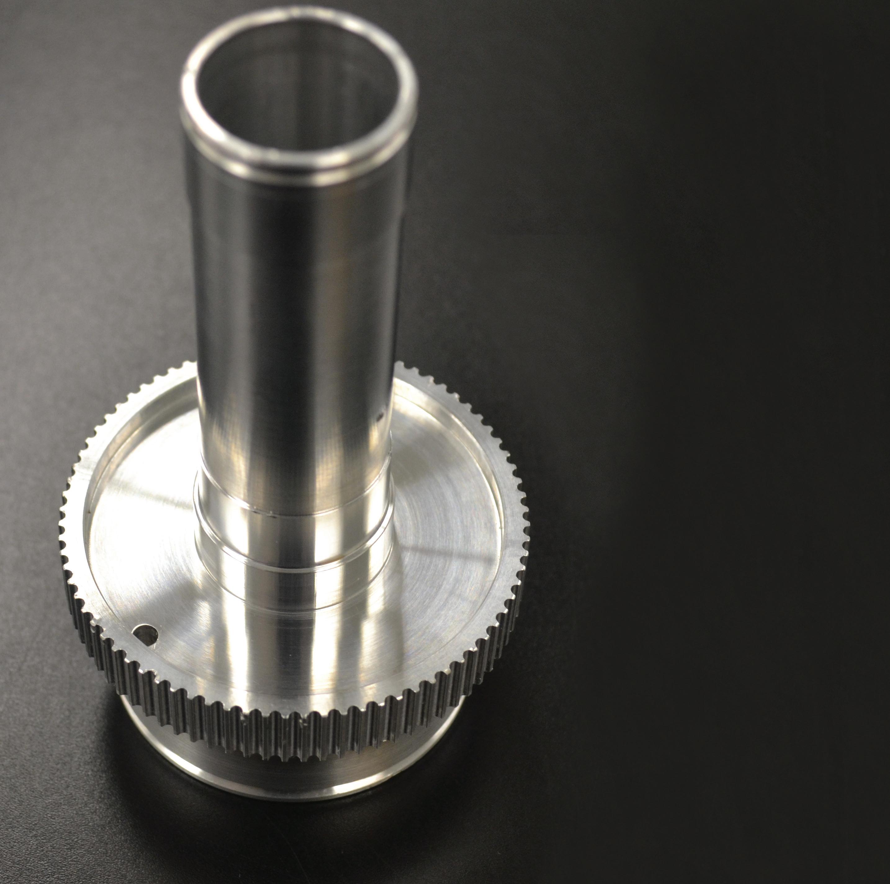

You’ve created a unique design. Now relax. We’ll take it from here.
Custom precision manufacturing.
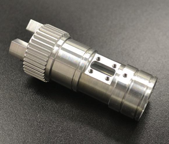
Manufacturer
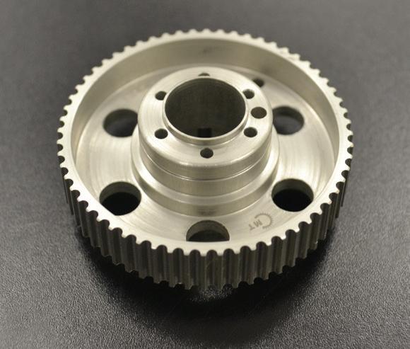
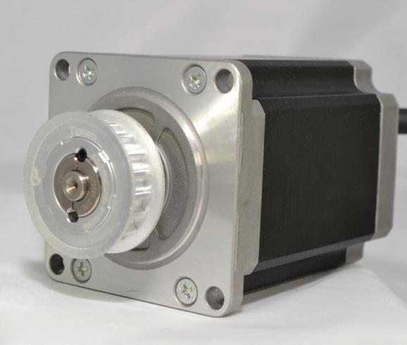
tooth design mentioned earlier. This newer high-torque gearbox offering offers extreme torsional rigidity and zerobacklash operation for applications that need superior precision in output motion. In contrast with other gear offerings that transmit power over lines of contact on gear teeth, meshing gears in the drive make almost full-surface contact. This allows for tooth contact that’s up to 6.5 times that of certain types of conventional involute teeth.
How does it work? In short, the gearbox guides a large array of individual teeth along an internal ring gear. The tooth geometry follows a logarithmic spiral that lets multiple teeth transmit power at once through hydrodynamic contact — covering much larger surface areas than traditional line contact. The result is a gearbox with zero backlash even at the zero crossing. The logarithmic spiral path of the teeth allows for synchronization accuracy that outperforms traditional hollow-shaft drives with comparable outer diameters.
The gearbox also boasts up to 91% efficiency — 18 to 29% better than traditional strain-wave and cycloidal geared arrangements.
As part of a drive system, hydrodynamic tooth contact of the gear drive also delivers high overload capability. Emergency stop torque is 150 to 300% better than comparable systems, and torsional rigidity is to 580% higher ... so gearboxes of other designs might need to be up to three times larger to deliver the same torque as a given thrusted-tooth gearbox. The gear design also allows for a very large hollow-shaft diameter in relation to the outer diameter — to 70% larger in some cases.
Whether defi ned by IEC, NEMA, JEMA, or other agencies, efficiency standards allow manufacturers and purchasers of electric motors to quantify efficiency, removing ambiguity and disparities in ratings among manufacturers. It also allows users to meet the MEPS required in their region or country, regardless of the origin of the motor.
According to the U.S. Department of Energy (DOE), electric motors are responsible for half the energy use in the U.S. manufacturing sector, and the International Energy Agency (IEA) estimates that electric motor-driven system account for more than 40% of global electricity consumption.
To promote energy savings, increase efficiency, and reduce operating costs for manufacturing operations, many countries and regions around the world have established minimum efficiency performance standards (MEPS) for motors used in industrial, commercial, and residential applications. The ability to establish and enforce MEPS, however, depends on a standardized testing and classification system for motor efficiency.
The U.S. began regulating electric motor efficiency in 1992 with the “Energy Efficiency Provision” of the Energy Policy Act (EPAct), and in 1997, the U.S. was the fi rst country to establish MEPS for electric motors. These regulations, however, only applied to motors manufactured in or sold to U.S. markets, with many countries around the world operating under their own efficiency rating systems and MEPS for electric motors.
To harmonize efficiency classifications for motors manufactured and sold in the global market, the International Electrotechnical Commission (IEC) introduced the standard IEC 60034-30 : 2008, which was updated in 2014 and is now referred to as to IEC 60034-30-1 : 2014, “Rotating electrical machines – Part 30-1: Efficiency classes of line operated AC motors.”
In addition to defi ning efficiency classes for electric motors, the IEC has also developed a standard that specifies how to determine motor efficiencies based on testing methods. This IEC 60034-2-1 : 2014 provides the basis for defi ning the efficiency classes in IEC 60034-30-1. Both standards were developed in conjunction with the National Electrical Manufacturers Association (NEMA), the Japan Electrical Manufacturers Association (JEMA), and the European Committee of Manufacturers of Electrical Machines and Power Electronics (CEMEP).
The IEC standard 60034-30-1 : 2014 applies to motors that meet the following criteria:
• Single speed induction or permanent magnet type motors (single- and threephase) operated on a sinusoidal mains supply
• Frequencies of 50 or 60 Hz
• 2, 4, 6, or 8 poles
• Rated output from 0.12 kW to 1,000 kW
• Rated voltage from 50 V to 1,000 V
• Capable of continuous operation at rated power without exceeding the specified insulation class (S1, continuous, duty)
• Ambient operating temperature between -20° C and +60° C
• Operating altitude up to 4000 m above sea level
For these motors, the IEC 60034-30-1 standard defi nes four efficiency classes:
• IE1: Standard Efficiency
• IE2: High Efficiency
• IE3: Premium Efficiency
• IE4: Super-premium Efficiency
The actual efficiency values required to meet each class (IE1, IE2, etc.) depend on the motor’s operating frequency, number of poles, and rated output, as shown in the example below.
Although much work has been done by the IEC to create a single, harmonized standard, some countries and regions still use local efficiency standards. But in many cases, the IEC efficiency levels overlap with local standards.
Case in point: In the U.S., NEMA efficiency standards for electric motors are still widely used, but for more than 95% of ratings, the NEMA premium classification is identical to the IEC classification of IE3.
For most induction motors rated from 0.75 to 357 kW, the U.S. MEPS is NEMA premium, and the EU MEPS is IE3 — making the required efficiency essentially the same in both regions. •
EDITORIAL
VP, Editorial Director Paul J. Heney pheney@wtwhmedia.com
Executive Editor Lisa Eitel leitel@wtwhmedia.com
Managing Editor Mike Santora msantora@wtwhmedia.com
Senior Editor Miles Budimir mbudimir@wtwhmedia.com
Senior Editor Rachael Pasini rpasini@wtwhmedia.com
Ryan Ashdown rashdown@wtwhmedia.com 216.316.6691
Jami Brownlee jbrownlee@wtwhmedia.com 224.760.1055
Mary Ann Cooke mcooke@wtwhmedia.com 781.710.4659
Jim Dempsey jdempsey@wtwhmedia.com 216.387.1916
Mike Francesconi mfrancesconi@wtwhmedia.com 630.488.9029
Jim Powers jpowers@wtwhmedia.com 312.925.7793
CREATIVE SERVICES & PRINT PRODUCTION
VP, Creative Director
Matthew Claney mclaney@wtwhmedia.com
Senior Art Director
Tory Bartelt tbartelt@wtwhmedia.com
Director, Audience Development Bruce Sprague bsprague@wtwhmedia.com
PRODUCTION SERVICES
Customer Service Manager
Stephanie Hulett shulett@wtwhmedia.com
Customer Service Representative Tracy Powers tpowers@wtwhmedia.com
Customer Service Representative JoAnn Martin jmartin@wtwhmedia.com
Customer Service Representative Renee Massey-Linston renee@wtwhmedia.com
Customer Service Representative Trinidy Longgood tlonggood@wtwhmedia.com
ONLINE DEVELOPMENT & PRODUCTION
Web Development Manager B. David Miyares dmiyares@wtwhmedia.com
Senior Digital Media Manager Patrick Curran pcurran@wtwhmedia.com
Digital Production Manager Reggie Hall rhall@wtwhmedia.com
LEADERSHIP TEAM
Senior VP, Engineering Courtney Nagle cnagle@wtwhmedia.com 440.523.1685
CEO Scott McCafferty smccafferty@wtwhmedia.com 310.279.3844
EVP
Marshall Matheson mmatheson@wtwhmedia.com 805.895.3609
CFO Ken Gradman kgradman@wtwhmedia.com 773.680.5955
FINANCE
Controller Brian Korsberg bkorsberg@wtwhmedia.com
Accounts Receivable Specialist Jamila Milton jmilton@wtwhmedia.com
MARKETING
VP, Digital Marketing Virginia Goulding vgoulding@wtwhmedia.com
Digital Marketing Manager Taylor Meade tmeade@wtwhmedia.com
Digital Design Manager Samantha Goodrich sgoodrich@wtwhmedia.com
Webinar Manager Matt Boblett mboblett@wtwhmedia.com
DESIGN


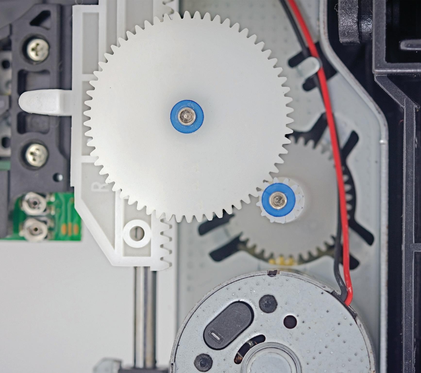
Plastic gears are primarily recognized for their quiet operation and resistance to rust — attributes that are important the food processing, medical equipment, and chemical processing industries, as well as in consumer applications. But plastic gears offer many other benefits, and advances in materials and manufacturing processes are helping to close the remaining performance gap between plastics and metals in gearing applications.
When determining whether a plastic gear will be suitable for a particular application, the most critical factor is environment. Some though not all plastics maintain less dimensional stability than metals ... and in a few cases, their strength and stiffness characteristics are dependent on temperature and exposure to
water or chemicals. When properly specified, plastic gears will exhibit no swelling or shrinking.
Plastic and metal gears also experience different types of contact under load. Metal gears have primarily line contact, with one tooth in mesh at a time. But plastic gear teeth have an involute surface that deforms under load, distributing the contact pressure across a larger surface and allowing contact between adjacent teeth. This provides load sharing among teeth and helps to improve the life of plastic gears in some applications — especially those with high impact loads and relatively low continuous loads.
The lighter weight of plastic gears means they have lower inertia than their metal counterparts, which is essential for aerospace and some military applications. In addition, most plastic gears can run without lubrication ... or can be embedded with lubricating materials such as graphite, silicone, or PTFE. However, some operating conditions benefit from (or even require) lubrication. Choosing a lubricant for plastic gears should take into consideration the environmental, load, and speed conditions in which the gears will operate. If the lubricant isn’t compatible with the plastic material, stress cracking or even failure of the plastic can result.
Due to sliding contact, plastic worm gears can in some cases experience heating which in turn decreases strength and accelerates wear. Speed capability is limited for such plastic worm gears, and lubrication is typically recommended.
The variety of plastics that are suitable for gear applications is extensive, but common choices include nylon, acetal, polycarbonate, polyphenylene sulfide, and polyurethane. The addition of glass fiber can improve the stiffness and heat conductivity of some materials, although it reduces the material’s fatigue endurance. Plastic gears can be processed by injection molding for lower cost than machined plastic gears. However, machined plastic gears typically offer better tooth strength and can be produced to meet higher AGMA quality levels than can be achieved with injection-molded versions.
A metal hub — either molded into the gear or assembled after manufacturing — can help in heat dissipation. It can also increase the rigidity of the gear and provide a secure surface for fastening the gear to the shaft. •
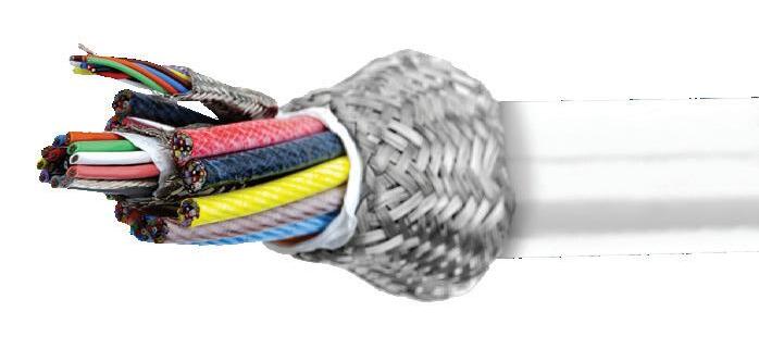


Designing efficient systems involves much more than simply understanding a few basic principles. There is a true art to balancing the specific requirements of an application in order to achieve the desired goals in the best possible way. Help us understand the unique needs of your application and together, we’ll develop something that surpasses what any of us could have done alone.
Contact your distributor to learn more, or visit clippard.com to request a free catalog and capabilities brochure.