AUGUST 2022 DESIGNWORLDONLINE.COM MOTIONCONTROLTIPS.COM Compact&LightWaveSpringsMOTIONHANDBOOKSYSTEMS
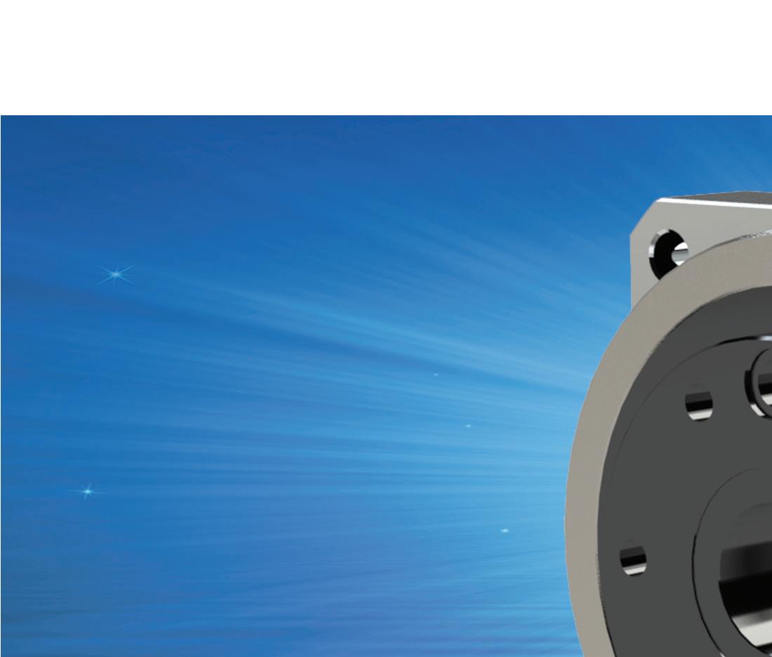
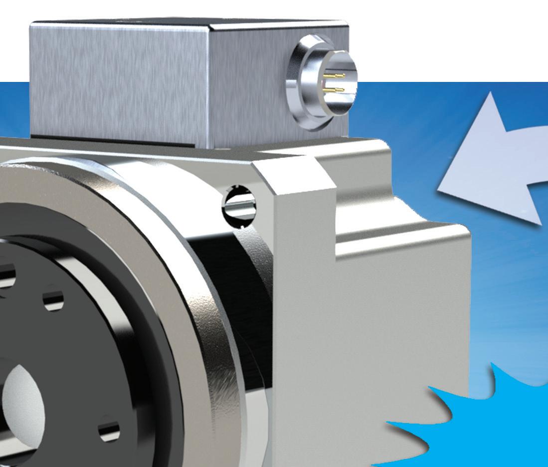
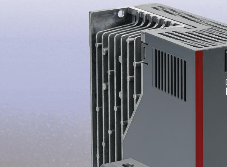
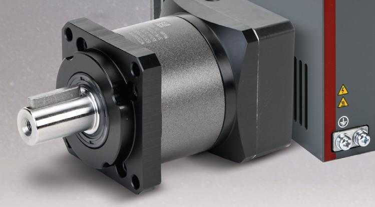
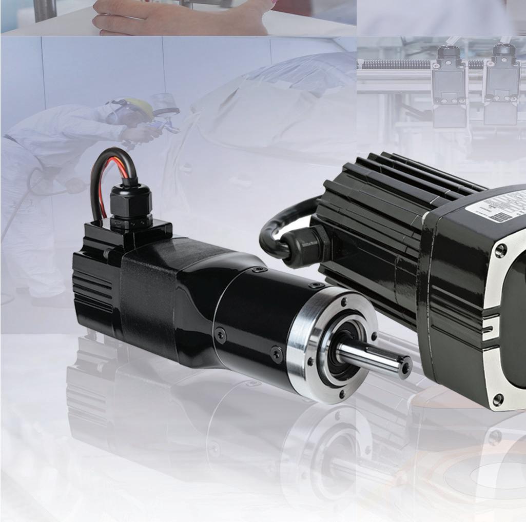
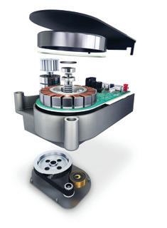
• Actuator + Integrated Servo Drive utilizing CANopen communication • 24VDC Nominal +7-28VDC Supply Voltage Range • Single Cable with only 4 wires needed: CANH, CANL, +24VDC, 0VDC • Zero Backlash • Dual Absolute Encoders • Panel Mount Connectors with 4 exit options • Output Sensing Encoder 14bit (16384 cpr) resolution • Input Sensing Encoder 15bit (32768 cpr) resolution • Control Modes Including Torque, Velocity, and Position Control, CSP, CSV, CST • Harmonic Drive HDL Software The FHA-C Mini Series is a family of extremely compact actuators that deliver high torque with exceptional accuracy and repeatability. As part of the FHA-C Mini family, an integrated servo drive version utilizing CANopen® communication is now available. This evolutionary product eliminates the need for an external drive and greatly improves wiring while retaining high-positional accuracy and torsional stiffness in a compact housing. The Servo Drive is in Actuator!the FHA-C Mini Actuator with Integrated Servo Drive Harmonic Drive is a registered trademark of Harmonic Drive LLC. CANopen is a registered trademark of CAN in Automation. 42 Dunham Ridge, Beverly, MA 01915 | 800.921.3332 | www.HarmonicDrive.net


AUGUST 2022 DESIGNWORLDONLINE.COM MOTIONCONTROLTIPS.COM Compact&LightWaveSpringsMOTIONHANDBOOKSYSTEMS
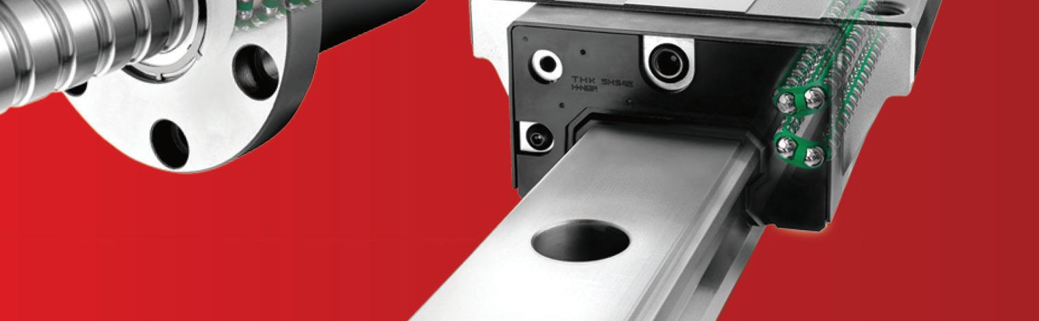
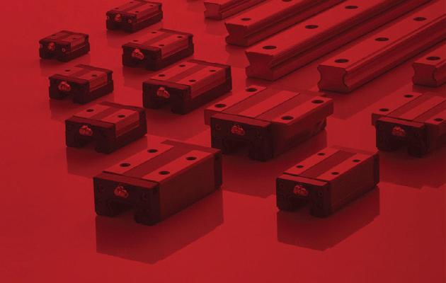
THK is committed to meeting the worldwide demand for linear motion products. At THK Manufacturing of America, Inc (TMA), we manufacture, assemble, and ship all over North America from our location in Hebron, Ohio. We’ve also ramped up our automating processes at existing facilities including our U.S. manufacturing plant where over 70% of THK Robotics Components are manufactured. Automated processes at this state-of-the-art facility enable increased production while maintaining the high standard of precision associated with our products. To learn more, call us at 1-800-763-5459 or visit www.thk.com. Quality Linear Motion Solutions from THK LOCAL MANUFACTURING WORLD-CLASS LINEAR MOTION 1–2 Week Delivery of Select LM Guides and Actuators QUICK SHIP COMPONENTS THK Manufacturing in Hebron, Ohio See us at: IMTS 2022 • September 12-17 Chicago • Booths 134802 & 134803


the #1 value in automation Order Today, Ships Fast! * See our Web site for details and restrictions. © Copyright 2022 AutomationDirect, Cumming, GA USA. All rights reserved. 1-800-633-0405 Research, price, buy at: www.automationdirect.com/servos LS Electric servo systems provide the most requested featuressetup wizards, auto tuning, built-in indexers and more - in an extremely cost-effective package: • 5 standard servo systems from 100W to 1kW • 200-230VAC single-phase input power on all systems • Control via high-speed pulse train, analog speed or torque signal, or internal indexing • Use with AutomationDirect CLICK, Do-more BRX, or Productivity Series PLCs; or any other host controller • Auto-Tuning and FREE setup software (with built-in o-scope function) • Fully digital with up to 1kHz velocity loop response • 30-day money-back guarantee • Two-year warranty NEW! LS Electric® L7C Servo Systems Starting at $610.00 (100W system with cables and I/O breakout) Servo Systems at Stepper Prices These L7C systems offer popular features at a fantastic price CompletestartingSystemsat: $610.00 (100w) Use our L7C Servo Selector Tool to size your system, and to specify all the required and optional accessories for YOUR application. Get all the parts you need on the first order! www.automationdirect.com/selectors/ls-servo Online L7C System Selector Tool Pre-matched LS Electric gearboxes offer easy mounting to the servo motor. Use these gearboxes to increase the available torque or to solve inertia mismatch problems. • 5:1, 10:1 and 20:1 gearbox models perfectly matched to each motor size • Increase the available output torque by 5x, 10x or 20x • Full motor output torque allowed for all pairings • Reflected inertia of the load is reduced by the square of the reduction ratio! • Mounting hardware included Need more torque? LS Electric® MSS Series Inline Planetary Gearboxes Starting at $264.00 (96200004)


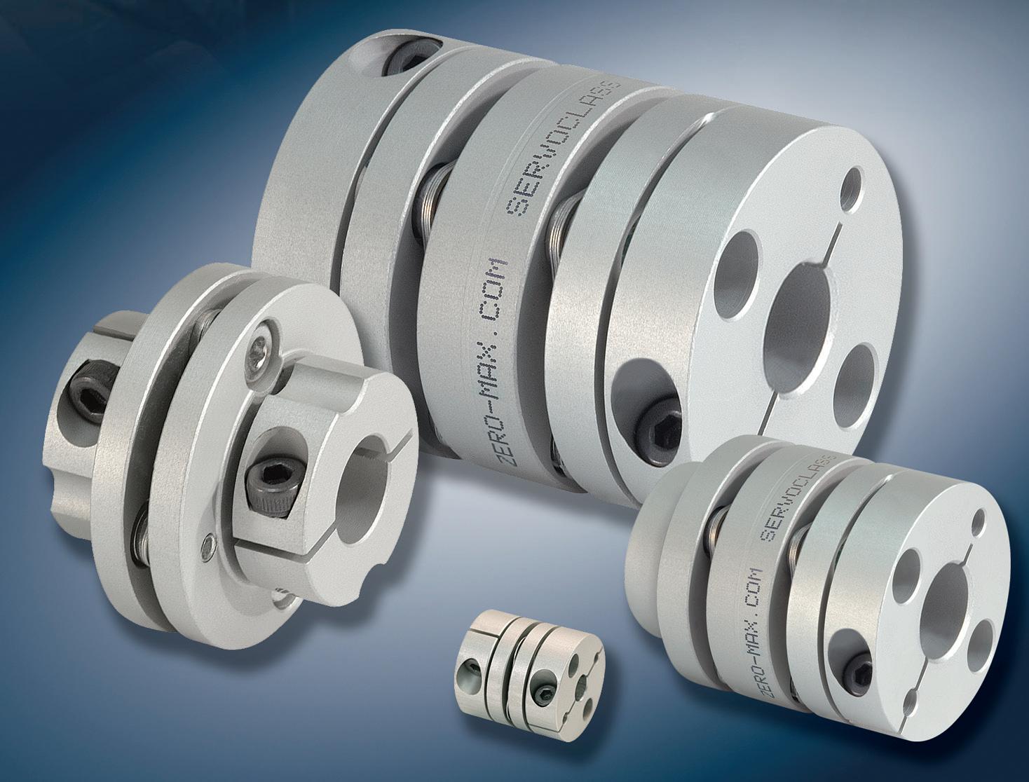
• Engineering Assistance / Fast Delivery www.zero-max.com 800.533.1731 PRECISE. ROBUST.AVAILABLE.


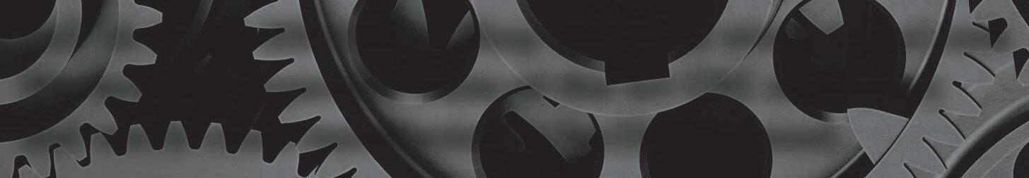
Early in the COVID-19 pandemic way back in 2020, we here at Design World did quite a number of stories on companies designing and building ventilators and other medical devices to accommodate the rapid uptick in need in the face of the COVID surge.
Now, two years later, we are far removed from those early emergency days and know a lot more about the virus and how it spreads. We also have many more effective ways to both combat the spread of the virus, including a number of highly effective vaccines which also lessen disease severity, as well as treatments should one get infected.
This was still in the emergency phase of the pandemic, with much uncertainty and the sudden and surging need for all sorts of medical supplies, including PPE of various types for front-line medical workers as well as the ventilators that were in short supply.
Other mitigation strategies, including the by now all-too-familiar social distancing and masking, can also be effective. However, there is still one huge area of impact that is often overlooked or just not covered in the media much at all. And this is where engineering comes in. From almost the beginning of the pandemic, we’ve known that the virus spreads primarily through the air, either in aerosol form or in droplets. The truth of the matter is that engineering can play a central role in dealing with COVID-19 and other respiratory diseases by focusing on air quality, something that HVAC engineers know all about.
A number of studies including from the EPA and the NIH as well as published studies in journals of building design and engineering conclude that HVAC systems play a central role in indoor air quality and what steps need to be taken to help reduce the risk of viral transmission and spread. Key areas include air movement in buildings including exchange rates for fresh air. Other factors include filter design in HVAC systems and using high quality filters to clear the air of contaminants such as bacteria and viruses. This means not only the coronavirus but other viruses that cause respiratory illnesses like the common cold and the flu.
Anyone who’s ever worked in a building with poor air quality, where people were always sneezing or catching colds or other respiratory ailments, knows the importance of good indoor air quality. In this sense, improving HVAC systems in the ways suggested can not only decrease the spread of pathogens such as the coronavirus but also others that make people sick, making for a better and healthier indoor environment all around.
HOW ENGINEERING - brushed or bldc motors - 5 amps per axis - 16 analog inputs - 16 on/off drivers - home and limit in - live tech support - made in the USA WWW.ALLMOTION.COM (510) 471-4000 30097 Ahern Avenue Union City, CA 94587 Technical Support (408) 460-1345 See the EZQUAD SERVO in action! 2.25” 4 AXIS SERVO from NEW! 4 DESIGN WORLD — MOTION 8 • 2022 Motion Systems Handbook CAN CLEAR THE AIR respiratory MILES BUDIMIR •SENIOREDITOR
Air quality is perhaps the single most important environmental factor that engineering can control in order to reduce the risk of illness. This can include better air filtration and air flow rates from building HVAC systems that increase supplies of fresh air, to something as low tech as opening windows to let in fresh outside air.
The world learned these lessons once before in the wake of the 1918 flu pandemic, which caused a shift in thinking in terms of building design and ventilation. A lot has already been done, but we can (and should) push to do more.


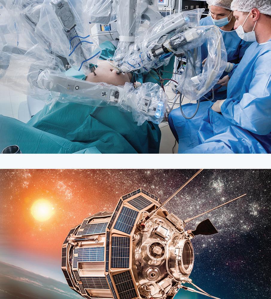
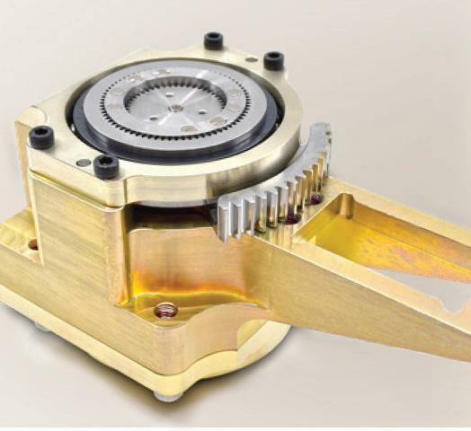
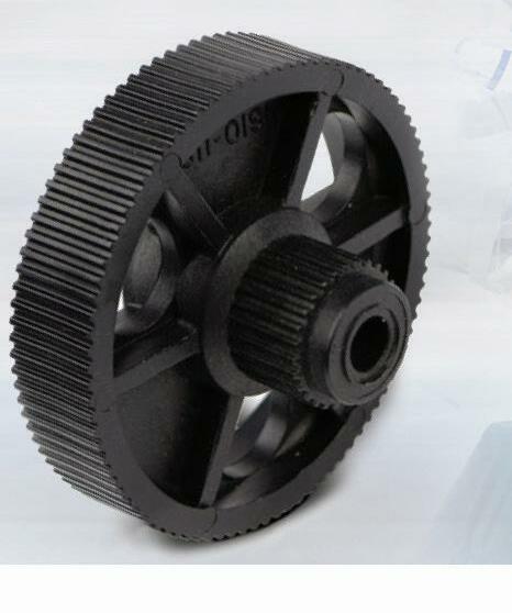
Call Us at 516-328-3300 or Shop SDP/SI at www.sdp-si.com We have the expertise, state-of-the-art CNC machinery and world-class manufacturing facility you need. SDP/SI offers the industry’s most comprehensive selection of precision gears, timing belt & pulley drives, mechanical components, motors, gearheads, and motion control products. ISO 9001 + AS9100 CERTIFIED Facing a design challenge? SDP/SI engineers provide problem solving, customized solutions. With over 70 years of engineering development and precision manufacturing experience, SDP/SI is a proven partner to the most recognized names in medical, aerospace, defense, and robotics industries. From prototype to high-volume production, SDP/SI high-quality components and subassemblies provide the reliable performance your application requires. Our products are found worldwide in surgical gear drivers, pharmaceutical processing & packaging, robotic surgery, patient positioning, drug delivery, pumps, and aerospace & defense applications including actuation/positioning systems, instrumentation, door releases, stabilization systems, camera positioning, weapons targeting, and cargo movers. • 88,000 Stock Components • Custom Gears and Gearboxes • Custom Timing Belt & Pulley Drive Systems • Couplings • Bearings & Linear Motion Products • Brushless DC Motors • Integrated Motor Drive Controllers • Frameless Motors • Miniature Gearheads • Planetary Gearheads


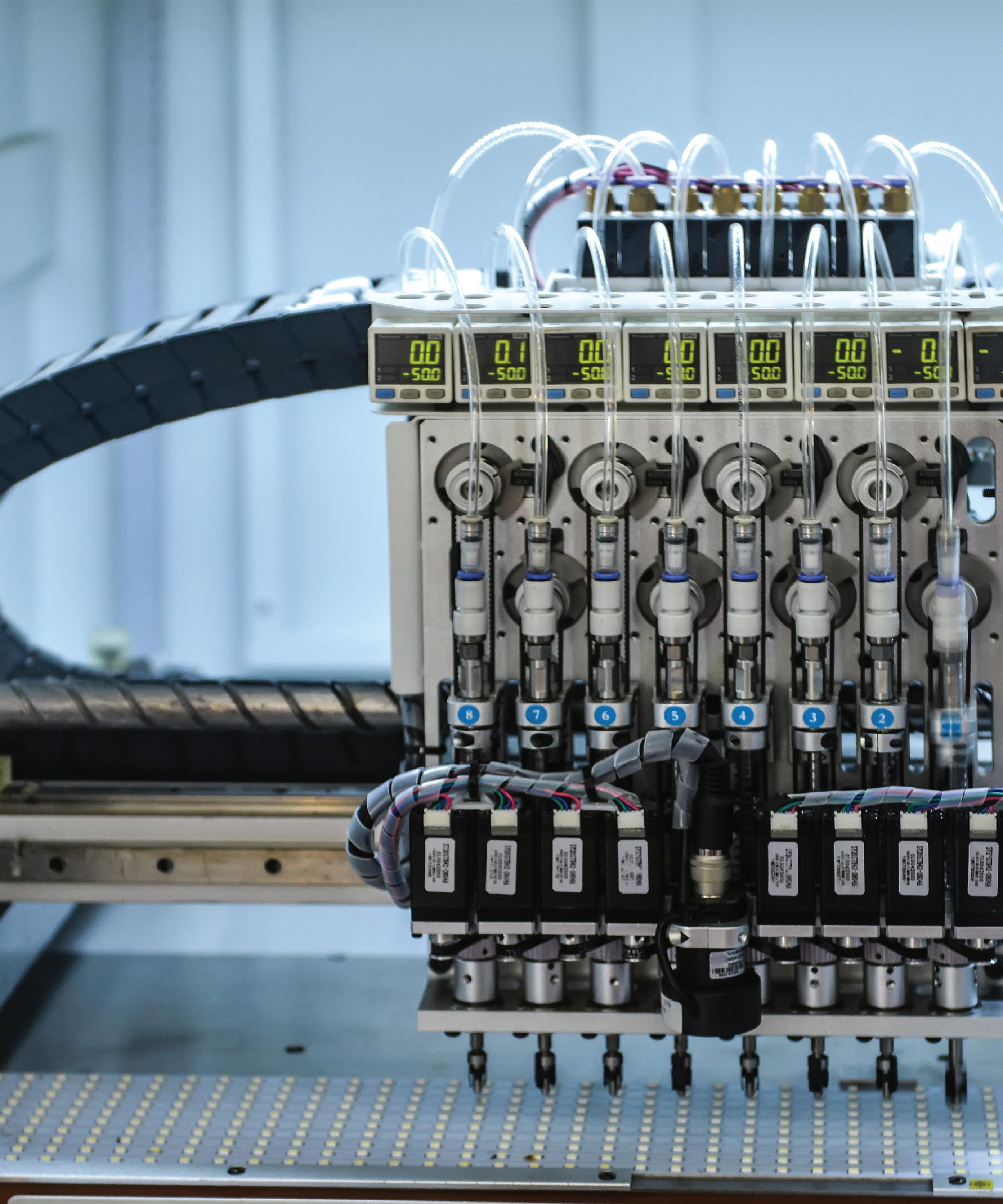
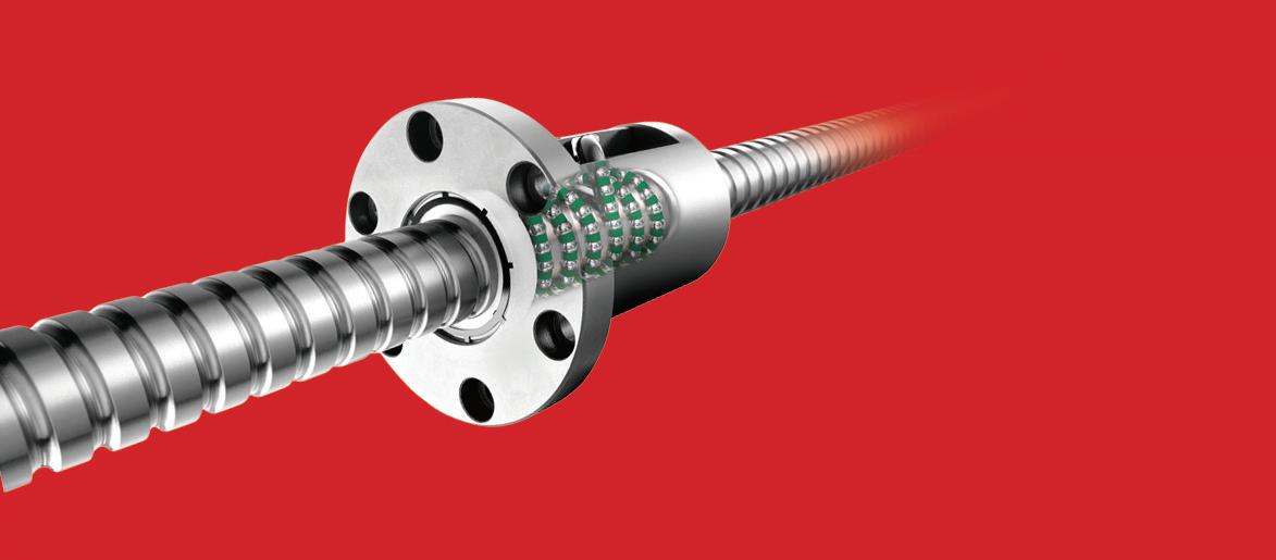
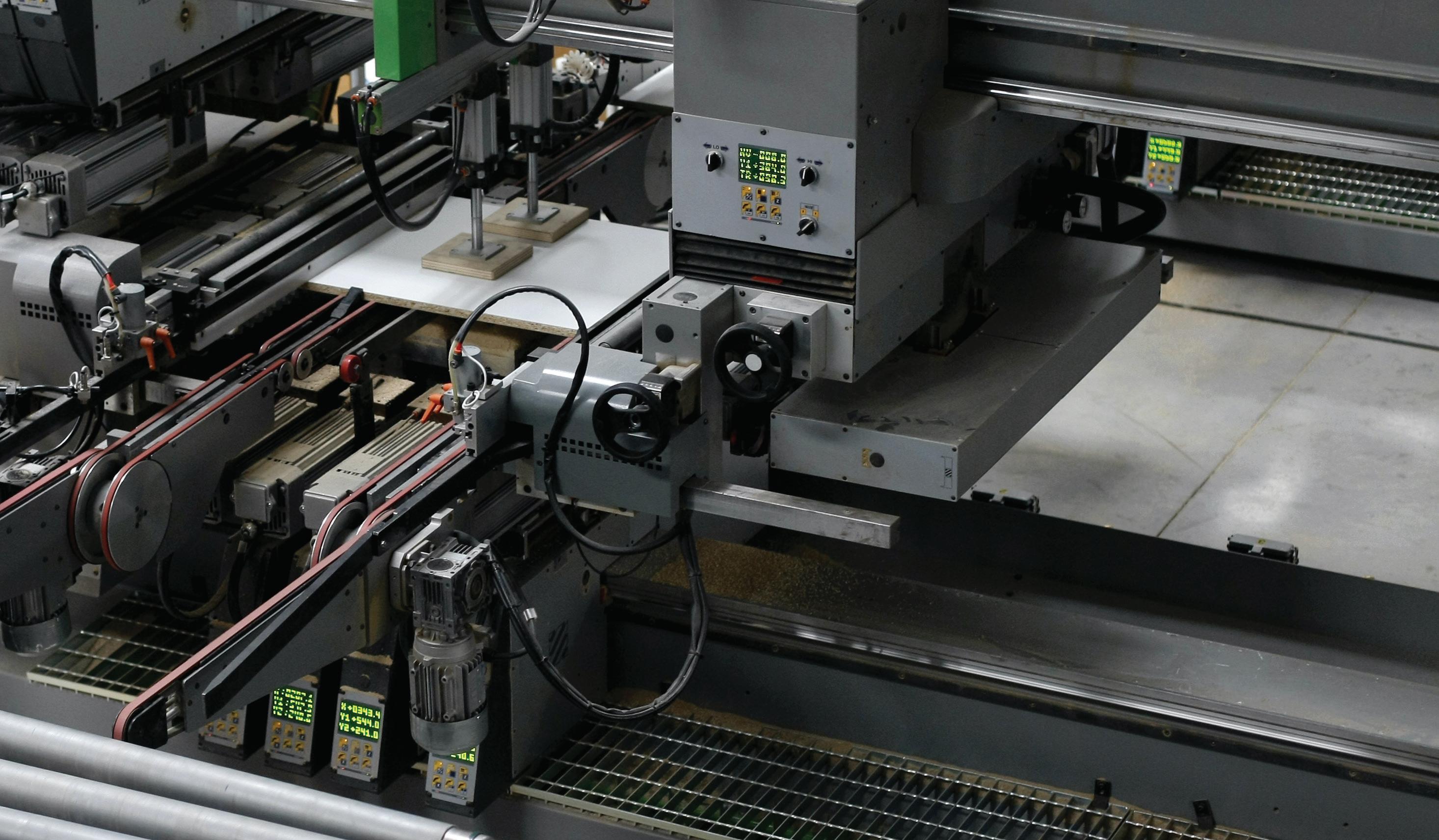
Contents VOLUME 8 NUMBER 3 ON THE COVER: SERVO COUPLINGS COMPLEMENT PRECISION LINEAR DRIVES AND PROFILE-RAIL LINEAR GUIDES IN THIS AUTOMATED ASSEMBLY EQUIPMENT. | COURTESY OF PHOTOMALL 6 DESIGN WORLD — MOTION 8 • 2022 motioncontroltips.com | designworldonline.com 4 EDITORIAL 8 STAFF 10 ACTUATORS — PNEUMATIC & ELECTRIC 14 BELTS & PULLEYS 17 BRAKES & CLUTCHES 18 CABLES & CONNECTIVITY 22 CONTROLLERS 24 CONVEYORS 26 COUPLINGS 31 DRIVES 33 ENCODERS & SENSORS 37 GEARING & GEARMOTORS 48 LINEAR GUIDES & RAILS • SLIDES & WAYS 52 SCREWS — BALL & ROLLER 54 MOTORS 58 SHOCK ABSORBERS • DAMPERS • GAS SPRING S 63 SPRINGS 65 TABLES & STAGES • CARTESIAN ROBOTS • GANTRIES 68 AD INDEX


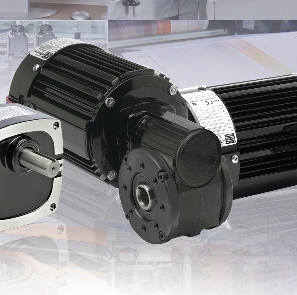
visit us at bodine-electric.com | info@bodine-electric.com | 773.478.3515 (USA) With over 1,400 standard products to choose from you can count on the engineers at Bodine to help you find a gearmotor with the right torque, power and speed for your application. We’ll get your design moving. bodine-electric.com The right gearmotor for your application.


Design W ldFOLLOW THE WHOLE TEAM ON TWITTER @DESIGNWORLD DESIGN WORLD does not pass judgment on subjects of controversy nor enter into dispute with or between any individuals or organizations. DESIGN WORLD is also an independent forum for the expression of opinions relevant to industry issues. Letters to the editor and by-lined articles express the views of the author and not necessarily of the publisher or the publication. Every effort is made to provide accurate information; however, publisher assumes no responsibility for accuracy of submitted advertising and editorial information. Non-commissioned articles and news releases cannot be acknowledged. Unsolicited materials cannot be returned nor will this organization assume responsibility for their care. DESIGN WORLD does not endorse any products, programs or services of advertisers or editorial contributors. Copyright© 2022 by WTWH Media, LLC. No part of this publication may be reproduced in any form or by any means, electronic or mechanical, or by recording, or by any information storage or retrieval system, without written permission from the publisher. Subscription Rates: Free and controlled circulation to qualified subscribers. Non-qualified persons may subscribe at the following rates: U.S. and possessions: 1 year: $125; 2 years: $200; 3 years: $275; Canadian and foreign, 1 year: $195; only US funds are accepted. Single copies $15 each. Subscriptions are prepaid, and check or money orders only. Subscriber Services: To order a subscription or change your address, please email: designworld@omeda.com, or visit our web site at POSTMASTER:www.designworldonline.com Send address changes to: Design World, 1111 Superior Ave., Suite 2600, Cleveland, OH 44114 WTWH Media, LLC 1111 Superior Ave., Suite 2600 Cleveland, OH 44114 Ph: 888.543.2447 FAX: 888.543.2447 VP, Editorial Director Paul J. Heney Managingpheney@wtwhmedia.com@wtwh_paulheneyEditor Mike Santora Executive@dw_MikeSantoramsantora@wtwhmedia.comEditor Leland Teschler Executive@dw_LeeTeschlerlteschler@wtwhmedia.comEditor Lisa Eitel Senior@dw_LisaEitelleitel@wtwhmedia.comEditor Miles Budimir Senior@dw_Motionmbudimir@wtwhmedia.comEditor Mary Gannon Senior@dw_MaryGannonmgannon@wtwhmedia.comContributingEditor Leslie Langnau @dw_3Dprintingllangnau@wtwhmedia.com EDITORIAL Video Manager Bradley Voyten Videographer@bv10wtwhbvoyten@wtwhmedia.com Garrett McCafferty gmccafferty@wtwhmedia.com VIDEOGRAPHY SERVICES VP, Creative Services Mark Rook Art@wtwh_graphicsmrook@wtwhmedia.comDirector Matthew Claney Senior@wtwh_designermclaney@wtwhmedia.comGraphicDesigner Allison Washko Graphic@wtwh_allisonawashko@wtwhmedia.comDesigner Mariel Evans Director,@wtwh_marielmevans@wtwhmedia.comAudienceDevelopment Bruce Sprague bsprague@wtwhmedia.com CREATIVE SERVICES & PRINT PRODUCTION Controller Brian Korsberg Accountsbkorsberg@wtwhmedia.comReceivableSpecialist Jamila Milton jmilton@wtwhmedia.com FINANCE IN-PERSON EVENTS Events Manager Jen Osborne Event@wtwh_Jenjkolasky@wtwhmedia.comMarketingSpecialist Olivia Zemanek ozemanek@wtwhmedia.com Customer Service Manager Stephanie Hulett Customershulett@wtwhmedia.comServiceRepresentative Tracy Powers Customertpowers@wtwhmedia.comServiceRepresentative JoAnn Martin Customerjmartin@wtwhmedia.comServiceRepresentative Renee Massey-Linston renee@wtwhmedia.com PRODUCTION SERVICES Web Development Manager B. David Miyares Senior@wtwh_WebDavedmiyares@wtwhmedia.comDigitalMediaManager Patrick Curran Front@wtwhseopatrickpcurran@wtwhmedia.comEndDeveloper Melissa Annand Softwaremannand@wtwhmedia.comEngineer David Bozentka Digitaldbozentka@wtwhmedia.comProductionManager Reggie Hall Digitalrhall@wtwhmedia.comProductionSpecialist Elise Ondak Digitaleondak@wtwhmedia.comProductionSpecialist Nicole Johnson VP,njohnson@wtwhmedia.comStrategicInitiatives Jay Hopper jhopper@wtwhmedia.com ONLINE DEVELOPMENT & PRODUCTION VP, Digital Marketing Virginia Goulding Digital@wtwh_virginiavgoulding@wtwhmedia.comMarketingManager Taylor Meade Digital@Taylortmeade@wtwhmedia.comMeadeDesignManager Samantha King Marketingsking@wtwhmedia.comGraphicDesigner Hannah Bragg Webinarhbragg@wtwhmedia.comCoordinator Halle Kirsh Webinarhkirsh@wtwhmedia.comCoordinator Kim Dorsey kdorsey@wtwhmedia.com MARKETING 2011- 2020 2013 - 2017, 2021 2014- 2016 2014 Winner 8 DESIGN WORLD — MOTION 8 • 2022 Design MotionWorld’sControl Classroom An online reference series for design engineers. Each motion installment features current trends, videos, typical and emerging applications and FAQs. learn more at: www.designworldonline.com/mc2 • Ball Screws • Cable Carriers • Conveyors • Couplings • DC Motors • Gearing • Integrated Motors • Linear Guides • + More MC² installments include stay up-to-date MC² Classroom installments cover topics including essential power-transmission and motion-control technologies for an array of OEM machines, powered end-user products, servo drives, and automated installations.


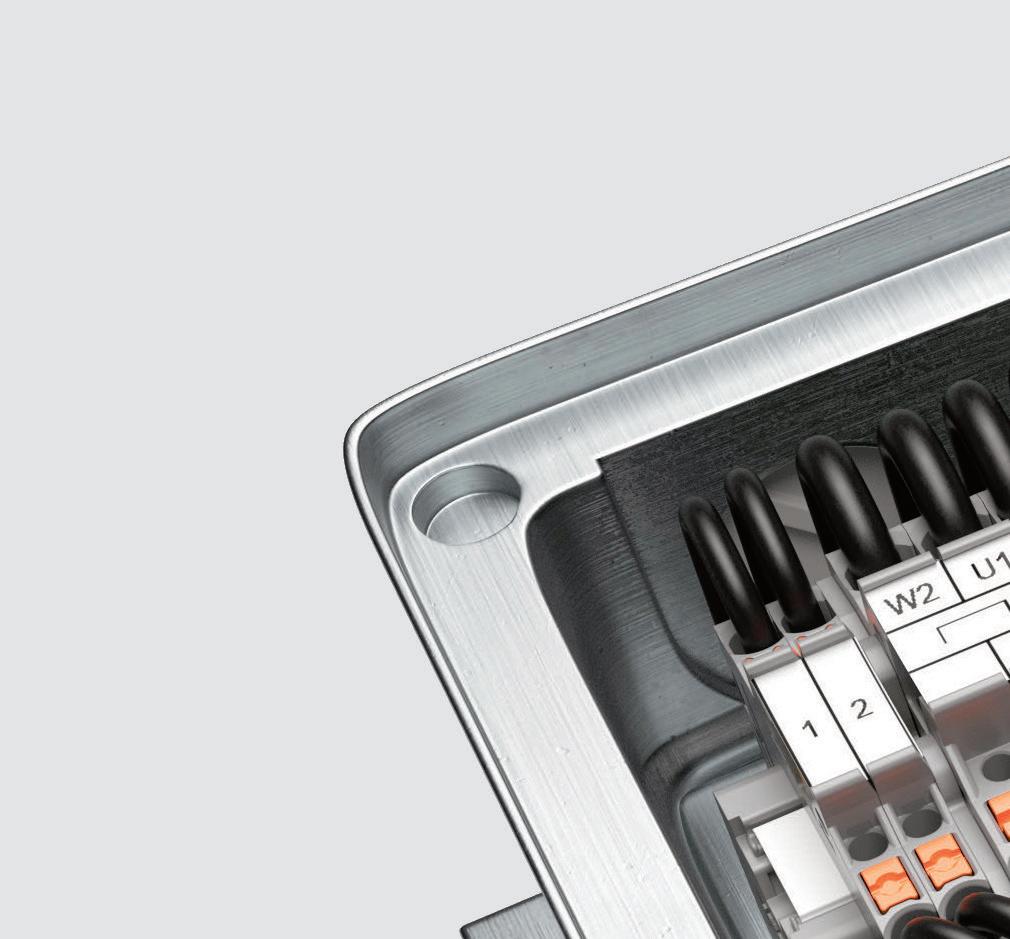
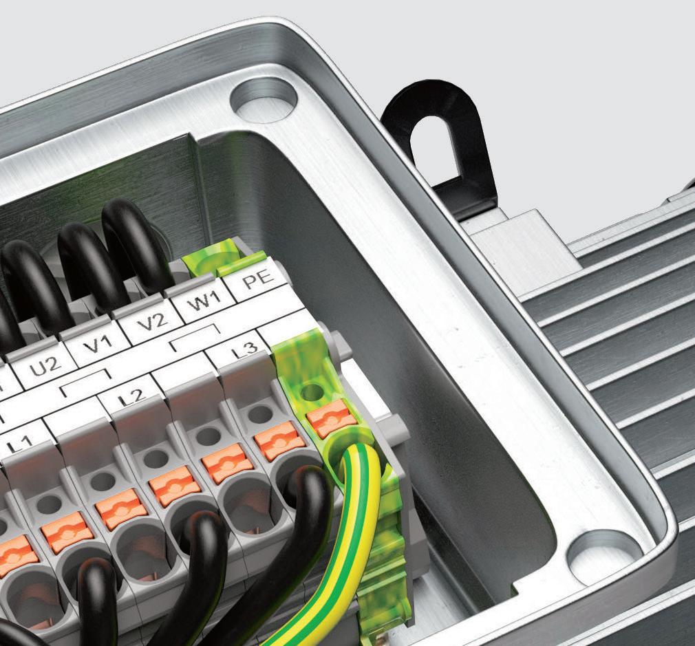
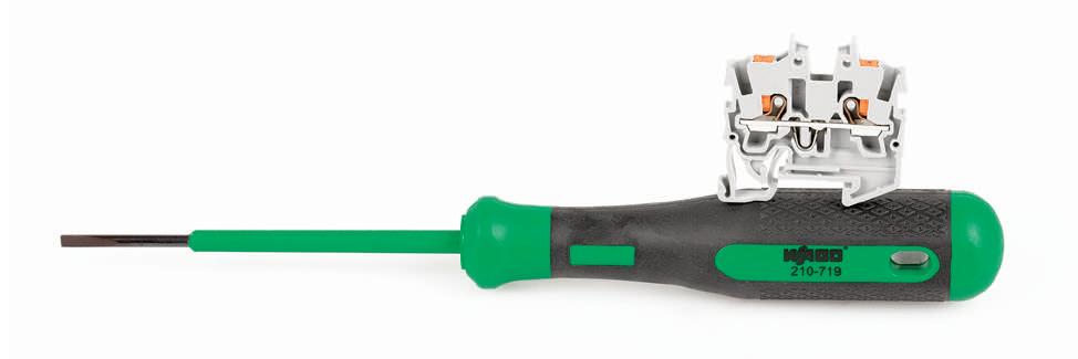
TOPJOB® S MINI TERMINAL BLOCK A REAL SPACE GENIUS The compact design of WAGO’s TopJob® S Mini Rail-Mount Terminal Blocks makes them ideal for work in tight spaces. Various mounting and actuation variants are also available for maximum flexibility; allowing you to choose your Mini terminal blocks based on use and convenience. Thanks to spring pressure connection technology, they can be used in junction boxes and are also suitable for vibration-proof connections. www.wago.us/ discover-terminal-blocks/mini-rail-mount-terminal-blocks PUSH-IN CAGE-CLAMP® TECHNOLOGY


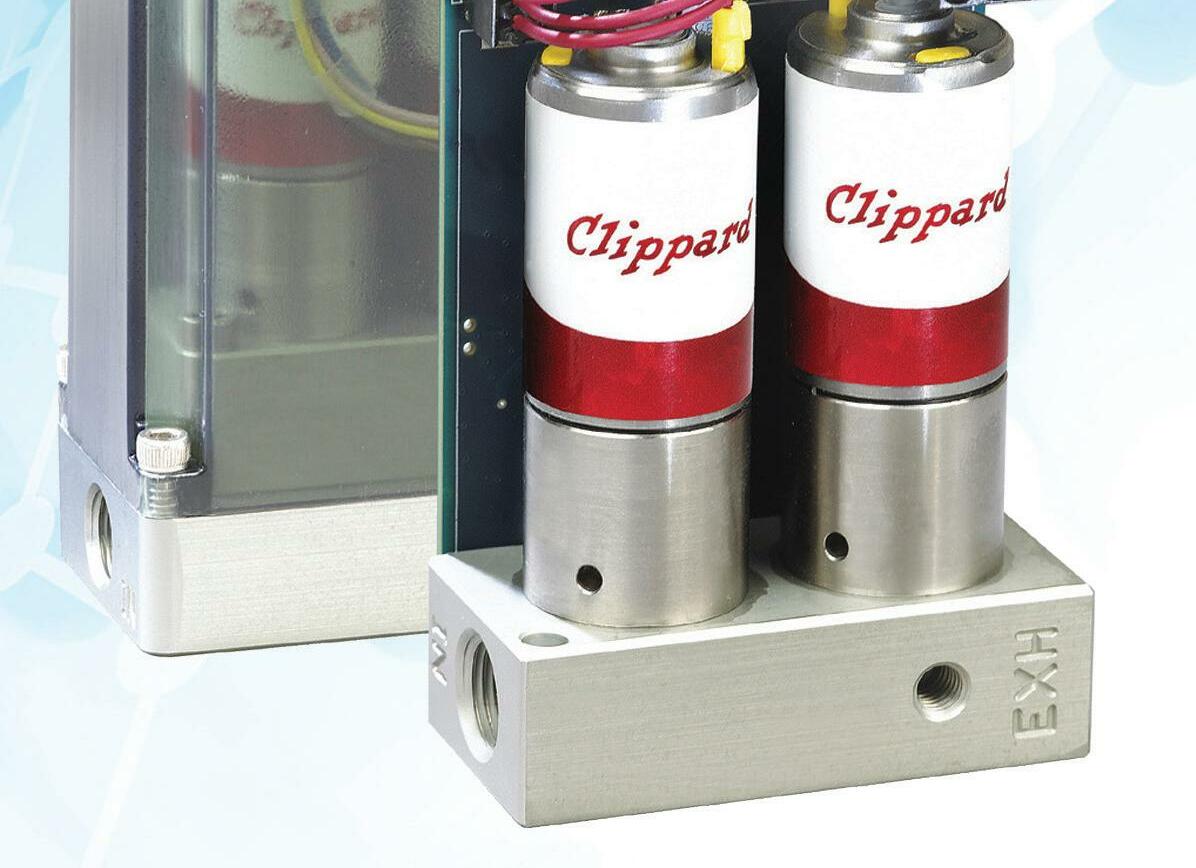
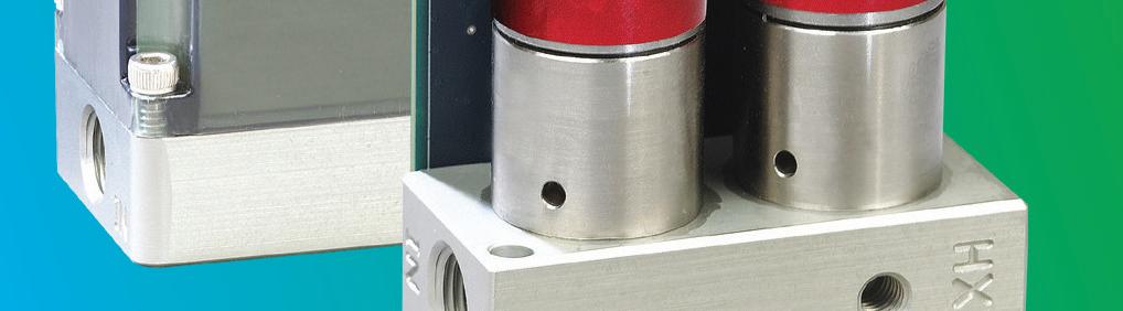
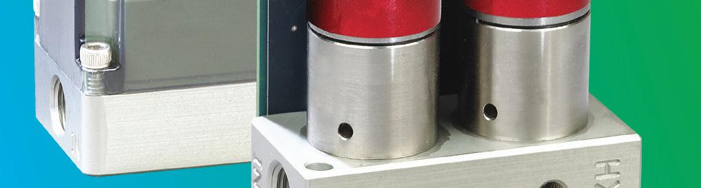
Of course, electromechanical actuators can provide accurate position and force control, but servo pneumatics have a much higher power density—that is, force capability for a given size. A servo pneumatic cylinder or actuator typically provides many times the force capability of an electromechanical actuator of a similar body size, which is a significant advantage in pressing, inserting, and tightening applications.
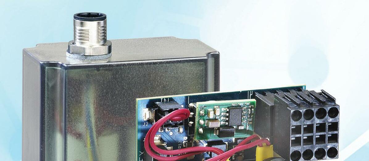
Servo pneumatics also operate with 24 Vdc power supplies, which allows them to be used in low-power applications. Lower power also reduces heat generation and thermal build-up, so they perform well in continuous-duty applications and high-temperature environments.
While electromechanical servo systems have been in use for decades, the adoption of servo pneumatics in industrial applications hinged on advancements in controls and software. Air is compressible, and this
COMPARING ACTUATOR TYPES 10 DESIGN WORLD — MOTION 8 • 2022 motioncontroltips.com | designworldonline.com | COURTESY OF VIOREL DUDAU
One drawback (real or perceived) to traditional pneumatics is air consumption. Air preparation and delivery costs money, and pneumatics can use a significant amount of air even when they’re not working.
Servo pneumatics, on the other hand, control air flow based on the required position and force. This leads to less air consumption than standard pneumatics, by as much as 30%. It’s important to note that servo pneumatics require higher quality air than standard pneumatics.
Motion Systems Handbook
Traditional pneumatics enable rapid, high-force, point-topoint motion. Servo pneumatics provide the same speed and force capabilities, with the advantage of higher accuracy positioning, not only at the ends of the stroke, but also at intermediate points along the travel. In addition to obtaining feedback on position, servo pneumatics also monitor and regulate air pressure, which enables precise control of the force that’s produced.
In addition to industry-standard filtration, a 5- mm filter is typically recommended for servo pneumatic systems.
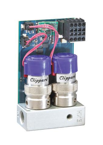
Pneumatic cylinders and actuators are sometimes called bang-bang devices — making quick moves from one end of their stroke to the other, with limited regulation of the force or move profile. On the other hand, electromechanical actuators with servo controls offer high levels of refinement in positioning, force/torque, and accuracy. Pneumatics offers a cost-effective solution for rather crude point-to-point moves while electromechanical actuators provide high precision, at a higher cost. However, there’s a spot between these two solutions where a relatively high level of control is needed, but without the complexity and cost of electromechanical servo driven systems. Bridging this gap are pneumatics that operate in a closed-loop system—in other words, servo pneumatics. A servo system is one that uses a feedback device and a controller to monitor and correct the system’s error (in position, speed, or torque/force). Hence, integrating a pneumatic cylinder or actuator with a feedback system and a controller that can issue commands based on that feedback, gives us a servo pneumatic device. Another key component of a servo pneumatic system is a proportional valve, which precisely regulates air delivery to ensure that the commanded position and/or force is achieved.
Servo pneumatics versus electromechanical actuators


Pneumatics is the technology of compressed air. Pressurized gas — generally air that is dry or lubricated — actuates an end effector and do work. End effectors in this context can range from the common cylinder to more application-specific devices such as grippers or air springs. Vacuum systems, also in the pneumatic realm, use vacuum generators and cups to handle delicate operations, such as lifting and moving large sheets of glass or delicate objects such as eggs. Pneumatics is common in industries that include medical, packaging, material handling, entertainment and even robotics. By its nature, air is easily compressible, and so pneumatic systems tend to absorb excessive shock, a feature useful in some applications. Most pneumatic systems operate at a pressure of about 100 psi, a small fraction of the 3,000 to 5,000 psi that some hydraulic systems see. As such, pneumatics is generally used when much smaller loads are involved. A pneumatic system generally uses an air compressor to reduce the volume of the air, thereby increasing the pressure of the gas. The pressurized gas travels through pneumatic hoses and is controlled by valves on the way to the actuator. The air supply itself must be filtered and monitored constantly to keep the system operating efficiently and the various components working properly. This also helps to ensure long system life. How do these fluid-power actuators work? Many industrial applications require linear motion during their operating sequence. One of the simplest and most cost-effective ways to accomplish this is with a pneumatic actuator, often referred to as an air cylinder. An actuator is a device that translates a source of static power into useful output motion. It can also be used to apply a force. Actuators are typically mechanical devices that take energy and .com
In a typical application, the actuator body connects to a support frame and the end of the rod is connected to a machine element that is to be moved. An on/off control valve is used to direct compressed air into the extended port while opening the retract port to atmosphere.
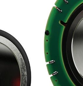
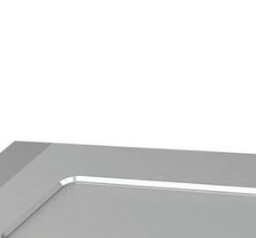
| designworldonline.com
The difference in pressure on the two sides of the piston results in a force equal to the pressure differential multiplied by the surface area of the piston.
The most popular style of pneumatic actuator consists of a piston and rod moving inside a closed cylinder. This actuator style can be sub-divided into two types based on the operating principle: single acting and doubleSingle-actingacting. cylinders use one air port to let compressed air enter the cylinder to move the piston to the desired position, as well as an internal spring to return the piston to the home position when the air pressure is removed. Double-acting cylinders have an air port at each end and move the piston forward and back by alternating the port that receives the high pressure air.
Undersized upstream components can cause pneumatic actuators to perform poorly, or even make them incapable of moving their loads.
Motion Systems Handbook 12 DESIGN WORLD — MOTION 8 • 2022 motioncontroltips
Pneumatic actuator benefits
But the past ten years or so have seen the development and integration of high-response valves and digital signal processors (DSPs) that can perform high-speed computations, making servo pneumatic systems a reality, capable of providing accurate, highly responsive positioning and force control.
If the load connected to the rod is less than the resultant force, the piston and rod will extend and move the machine element. Reversing the valving and the compressed air flow will cause the assembly to retract back to the home position. Pneumatic actuators are at the working end of a fluid power system. Upstream of these units, which produce the visible work of moving a load, are compressors, filters, pressure regulators, lubricators, on/off control valves and flow controls. Connecting all these components together is a network of piping or tubing (either rigid or flexible) and fittings. Pressure and flow requirements of the actuators in a system must be considered when selecting these upstream system components.
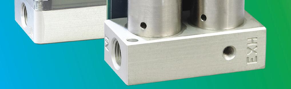
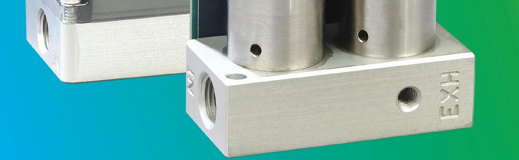
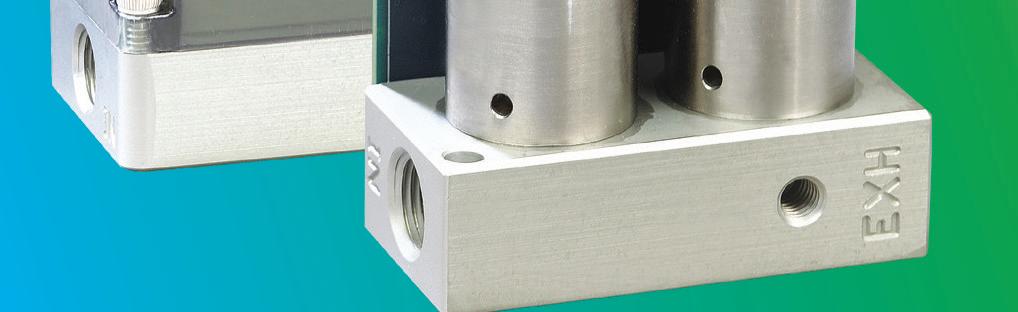
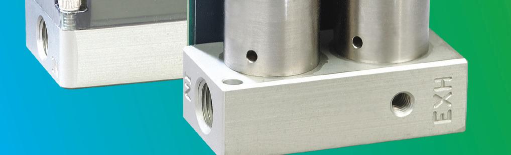
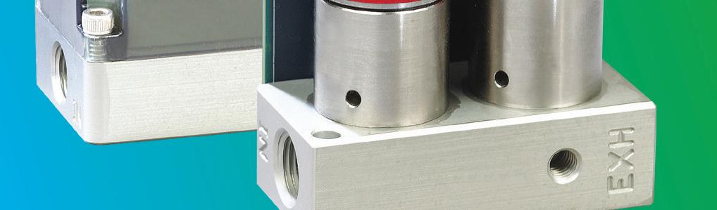
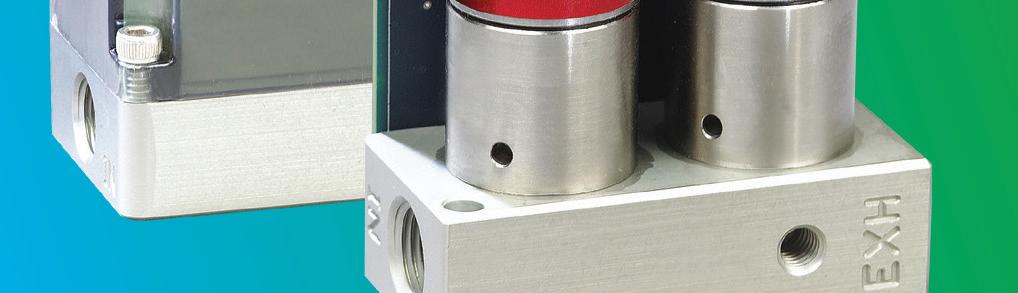
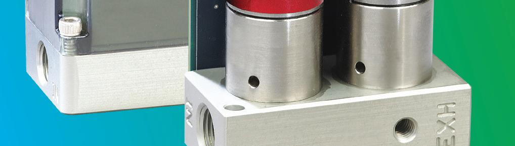
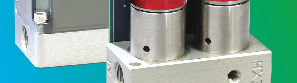
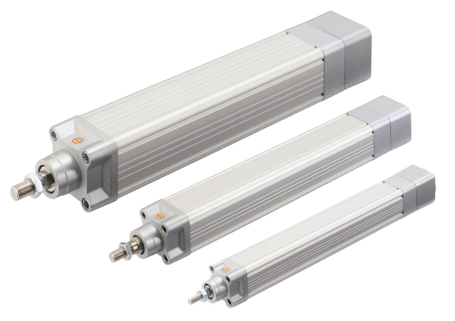
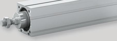
THE NEW AVENTICS SERIES SPRA ELECTRIC ROD-STYLE LINEAR ACTUATOR IS A COST-EFFECTIVE PERFORMANCE SOLUTION. THE SERIES SPRA PROVIDES ENHANCED LOAD CAPACITY, ACCURACY AND RELIABILITY, AS WELL AS OUTSTANDING PRECISION AND REPEATABILITY. EMERSON OFFERS THE SERIES SPRA WITH THREE DIFFERENT SCREW TECHNOLOGIES THAT ALLOW IMPLEMENTATION WITHIN A WIDE RANGE OF APPLICATIONS — MAKING IT A VERSATILE AND FLEXIBLE SOLUTION. convert it into controlled motion. That motion can be for a variety of functions — including blocking, clamping, or ejecting.
variable is much more difficult to define and model than the compliance, or backlash, in an electromechanical system. Before servo pneumatics could be commercialized, pneumatic control algorithms capable of considering this nonlinearity had to be created.
Pneumatic actuators are mechanical devices that use compressed air acting on a piston inside a cylinder to move a load along a linear path. Unlike their hydraulic alternatives, the operating fluid in a pneumatic actuator is simply air, so leakage doesn’t drip and contaminate surrounding areas. There are many styles of pneumatic actuators, including diaphragm cylinders, rodless cylinders, telescoping cylinders and through-rod cylinders.
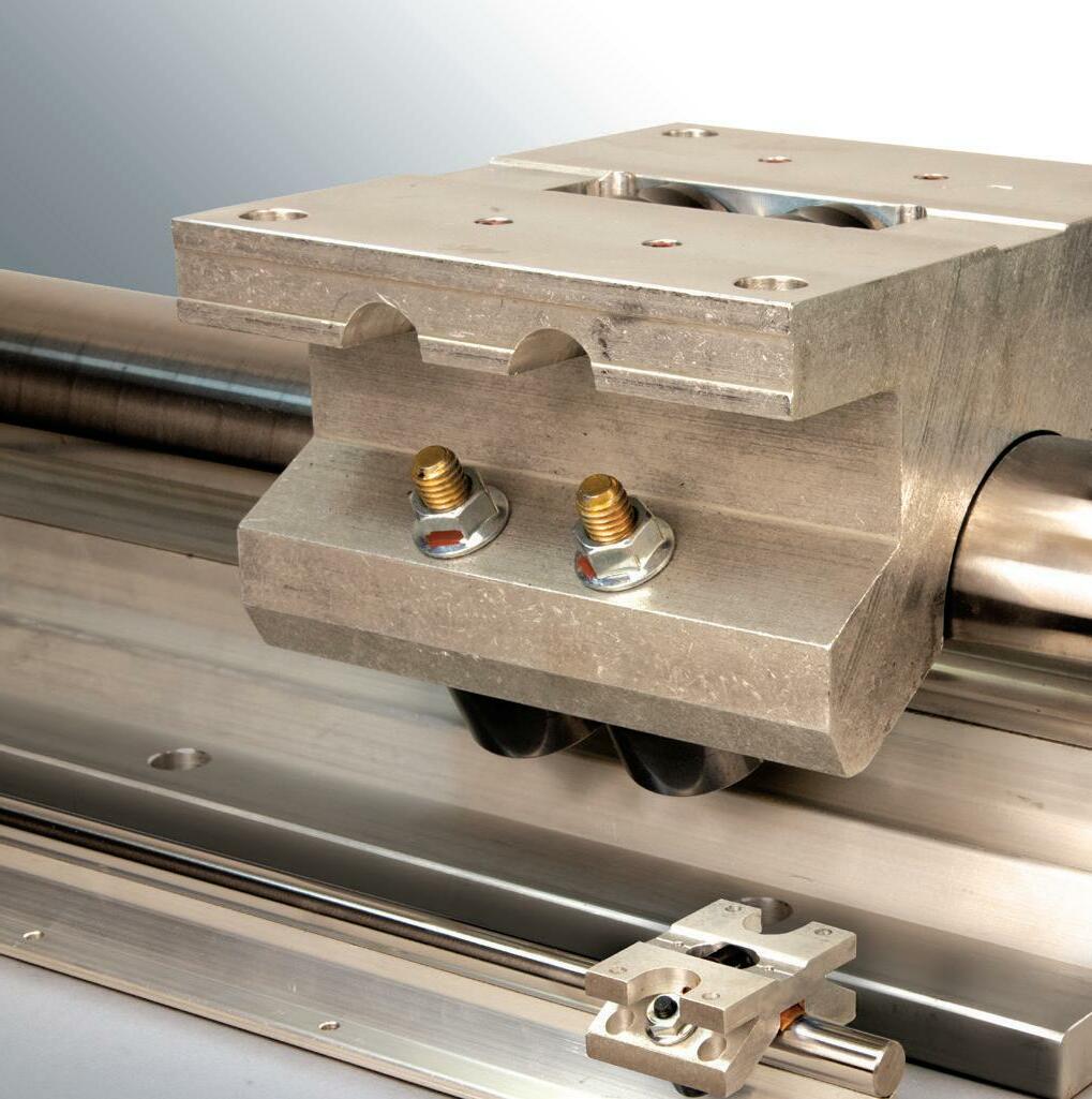
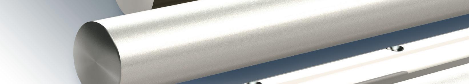
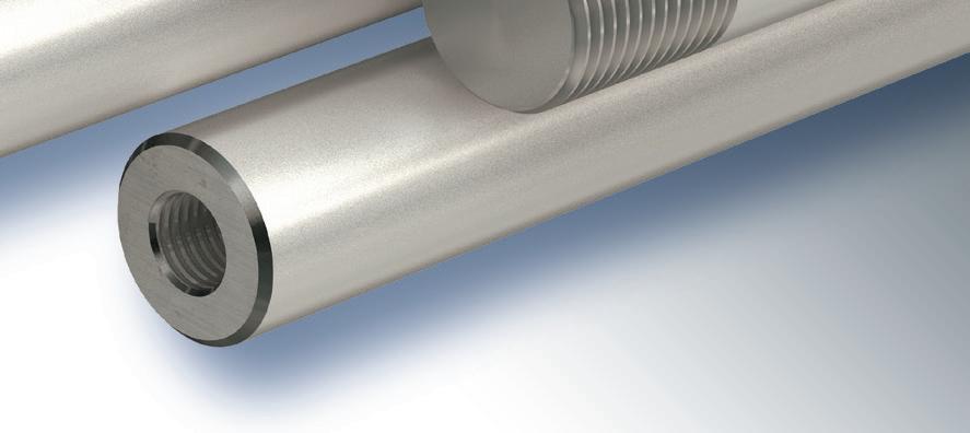
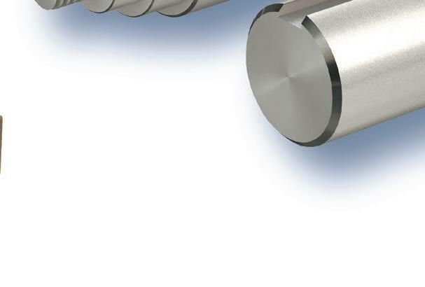
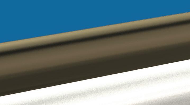
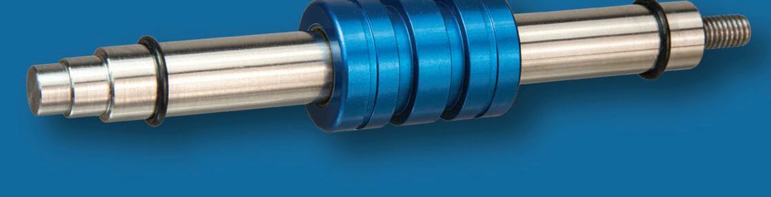
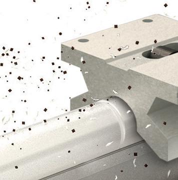
Request a FREE Sample at6402 E. Rockton Rd. Roscoe, Illinois leelinear.comsales@leelinear.com+1.800.221.0811USA Flexibility to Meet Your Needs LEE Linear has the ability to manufacture custom shafting to required standards in a short amount of time, eliminating downtime and increasing profits for our customers. Special machining capabilities include threading, diameter reduction, flats, keyways, plating, and more. Steel, Stainless Steel, and Aluminum Shafting cut to length and optimized for use with LEE Linear bearings. Large cam follower design delivers superior forandSimplifiedresistancecontaminationandexcelsinapplicationsrequiringjoinedshaftsorrailassemblies.installationalignmentmakeslowersystemcosts. PillowRoller Blocks are well suited for heavy loads and long travels. bit.ly/LEESample


Motion Systems Handbook
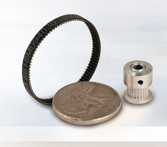
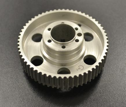
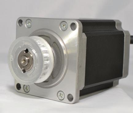
Belts can either be the source of motion themselves or transmit power or motion, depending on the setup. A typical belt drive includes the belt and a number of pulleys, as well as clutches and mechanisms for ratio variation. In some cases belt drives function as a conveyor, with the load riding on the belt. In other situations such as in actuators or machineaxis coupling, belt drives function as the device to convert rotary motion of an electric motor to linearIndustrialmotion. belt drives include a number of variations, including the common design of a rubber belt that wraps around drive pulleys, which are in turn driven by electric motors. The belt also typically wraps around one or more idler belts – cords embedded into the belt rubber that today’s belt drives thoroughly modern power
KEEPING BELT AND PULLEY 14 DESIGN WORLD — MOTION 8 • 2022
The pulleys used in belt drives are typically metal or plastic, and the most suitable depends on a number of factors including the required precision, price, inertia, color, magnetic properties and the engineers’ preference based on experience. Plastic pulleys with metal inserts or metal hubs are a good compromise. Engineers use belt drives in motion systems for a number of reasons. For starters, belt drives are simple and relatively inexpensive compared with other drive technologies. Plus, modern belt drives require little if any maintenance and are relatively quiet and efficient, even up to 95% or more in some cases. Another plus is that they are more tolerant of shaft misalignment, meaning that they do not require axially aligned shafts. motioncontroltips many forms; from the latest linear motor designs to mechanical means systems involving chains or belts and pulleys can carry the majority of the belt load – are stronger than ever. Made of polyester, aramid, fiberglass or carbon fiber, these tensile cords make
.com | designworldonline.com
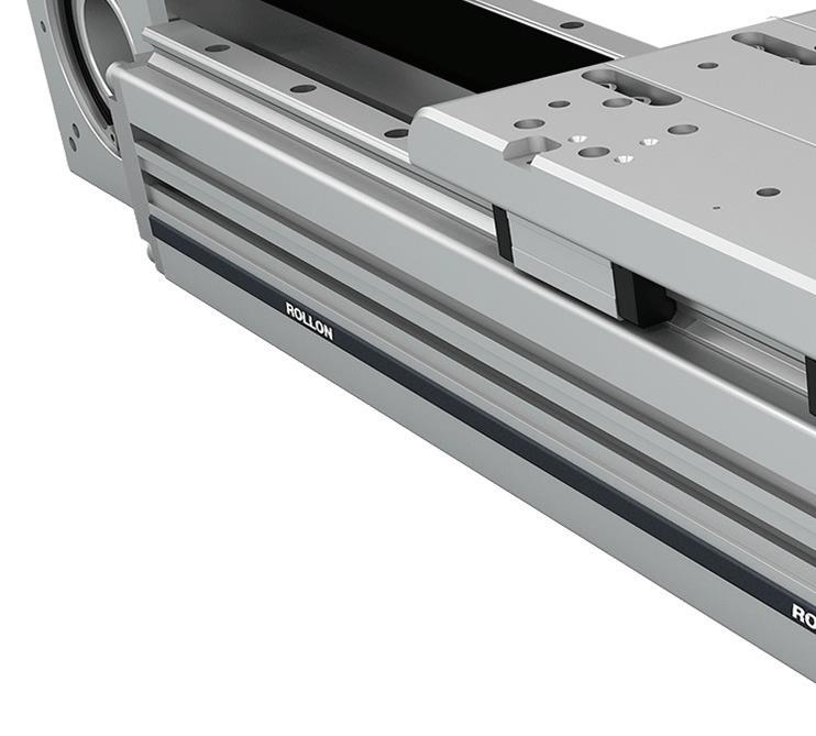
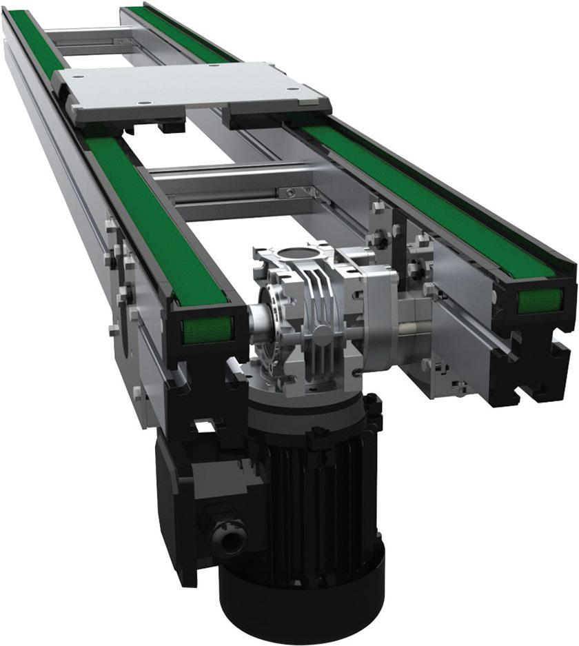
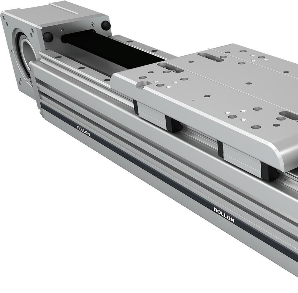
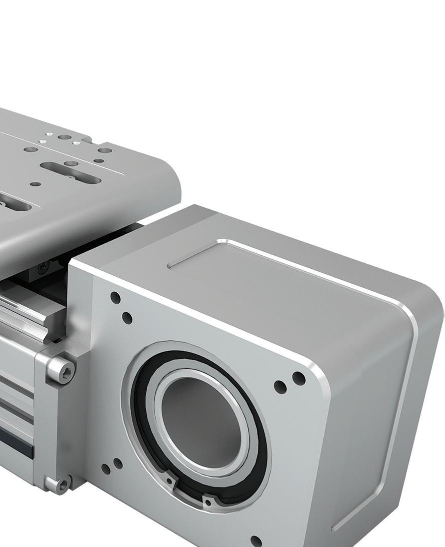
BELT-DRIVEN LINEAR ACTUATORS, SUCH AS THE SMART SYSTEM FROM ROLLON SHOWN HERE, CAN SUPPORT HEAVY LOADS AND OFFER LOW MAINTENANCE IN A RANGE OF APPLICATIONS IN AUTOMATED MANUFACTURING. MISALIGNMENT OF THE BELT PULLEYS CAN CAUSE SEVERAL ISSUES, INCLUDING BELT WEAR AND THE BELT “JUMPING” OFF THE PULLEY DURING OPERATION. COURTESY OF TIMKEN
|
DRIVES ON TRACK involving screw actuators. Mechanical drive systems involving chains or belts and pulleys can also be a reliable option.


DrivesSynchronousCustom Precise. Reliable. Trusted. American Engineering | American Made © 2017 Custom Machine & Tool Co., Inc. Manufacturer of Power Transmission and Motion Control Components You’ve created a unique design. Now relax. We’ll take it from here. Custom precision manufacturing.


During operation, if the belt comes off the sheave or turns over, this can indicate misaligned pulleys or contamination in the drive. Other conditions that can cause the belt to jump off the sheave or turn over include insufficient belt tension, significant vibrations in the drive, and shock loads.
Failure to carry the load
Any abnormal wear – whether on the top, bottom, sides, or grooves of the belt – can indicate a problem in the application. Wear on the top or bottom corners of the belt is often caused by a poor fit between the belt and the sheaves, due to incorrect sizing or due to wear on the sheaves. Wear on the bottom of the belt is also a sign of poor fit between the belt and the sheaves, although debris in the drive can also cause bottom surface wear.
A belt that’s unable to carry the designed load will often slip and is an indication that the drive is improperly sized or has insufficient tension. If sizing and tension are found to be sufficient, other potential causes are damaged tensile cords or worn sheave grooves.
Broken belt
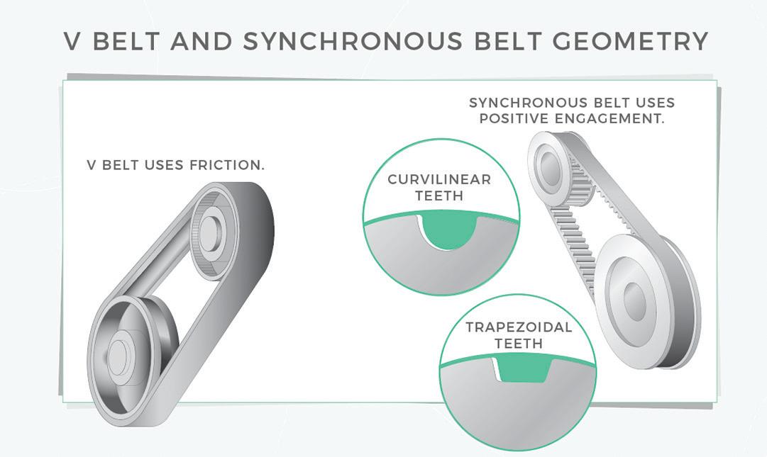
Motion Systems Handbook LINE SHAFT CONVEYOR BELTS Original Equipment and Connectable CUSTOM MADE IN INCH, METRIC & O-RING SIZES • Round, Flat and Connectable Polyurethane Belts • Very Clean Operation • Eliminates Tensioning Devices • Exceptional Abrasion Resistancexxxxxxxxxxxxxx pyramidbelts.com POWER TRANSMISSION-PART CONVEYING PYRATHANE® BELTS Lifetime Warranty Against Manufacturing Defects AN ISO 9001 CERTIFIED COMPANY 641.792.2405 sales@pyramidbelts.com 19Pyramid_4x475_PC.indd 1 12/4/2018 4:56:13 PM 16 DESIGN WORLD — MOTION 8 • 2022 SHOWN HERE IS THE DIFFERENCE BETWEEN FRICTION BELTS AND SYNCHRONOUS BELTS – THE FORMER USE FRICTION AND HAVE MORE POTENTIAL FOR ERROR IN POSITIONING, WHILE THE LATTER MAKE USE OF TOOTHED PULLEY ENGAGEMENT.
Belt comes o the sheave
Focus on V-belt troubleshooting
Abn mal wear
If belt surfaces — especially the belt sidewalls or the top surface — become hard or stiff, this can indicate that the belt is slipping (which increases heat and friction), or that it has been exposed to excessive heat from the environment or the process. Similarly, contamination from oil other chemicals can cause the belt — in this case, typically the top surface — to swell or become flaky or sticky.
Although there are more than a dozen symptoms of premature wear and impending failure for V-belts — ranging from visible damage to audible noise — there are a few key ways that these friction-based belts can fail during operation. To help users determine the root cause of a failure or signs of potential failure, V-belt manufacturers provide troubleshooting guides that suggest causes and remedies for a wide range of issues. Here, we’ll look at fi ve common ways that V-belts can fail and the most probable causes of each condition.
Edge c d damage Edge cord damage or failure can be a product of sheave misalignment, which causes the belt to track unevenly and, in some cases, twist during operation. Damaged tensile cords can also lead to edge cord damage or failure.
The earliest belt iteration — and one that’s still economical today — is the friction-based V-belt design. These pair a belt with a pulley (often on an electric motor’s geared output shaft) to provide reliable operation in a variety of end-user and industrial designs. Modern V belts are rubber, urethane synthetic, and neoprene designs with either a V or trapezoidal profile. The latter increases the amount of contact between V belts and pulleys to minimize tension needed to transmit torque. Even so, polyurethane outperforms rubber thanks to its higher resistance to chemicals and adaptability to specialized profiles.
The clearest sign of accelerated belt wear or failure is a broken belt, which typically indicates that the tensile cords have been damaged. Damage to these load-carrying members can be caused by severe shock loads during operation or by using a belt that’s under-sized for the application.Tensilecord damage can also occur if the belt is pried or rolled onto the sheave during installation. In extreme cases, foreign objects in the drive can damage the belt severely enough to cause breakage.


plys
sheets. INPUT SHAFT DC POWER INPUT Brakes & clutches
MAGNETIC-PARTICLE ACTION
Magnetic-particlestator.
paper-feeding
ELECTROMAGNETICMAGNETIC-PARTICLECLUTCHES
Constraints: Magnetic-particle brakes and clutches are typically used on horizontal applications, as vertical arrangements can cause the particles to fall to the bottom of their cavity and degrade torque capacity. That’s especially true where machinery is subject to vibration. Though usually quite smooth running, a faint stiction of these units at near-zero rpm may render them inappropriate for exceptionally slow axes. At the other end of the spectrum, these brakes and clutches don’t do particularly well on axes involving exceptionally fast slip speeds … as such situations tend to make magnetic-particle units exceed their heat-dissipation limits. In fact, magnetic-particle components must be sized to accommodate the application’s torque and heat-dissipation requirements.
Another caveat is that eventually the magnetic particles can indeed wear out … though usually that’s only a risk on tensioning axes involving constant slip and heat sufficient to eventually degrade the particles’ magnetic capacity. In-field serviceability is also limited for magnetic-particle clutches and brakes.
AND THAT’S HELPFUL WHEN THEY’RE MOUNTED
BRAKES ARE TORQUE DENSE.
TO MOTORS REQUIRING MINIMAL ADDITION OF INERTIA — WHEN DRIVING AXES NEEDING QUICK ACCELERATIONS AND REVERSALS FOR EXAMPLE. 17DESIGN WORLD — MOTION8 • 2022motioncontroltips.com | designworldonline.com OUTPUT SHAFT FIELD MAGNETICCOILPARTICLES ROTOR INPUTFLUXSHAFTPATH
Magnetic-particle clutches and brakes include a profiled magnet-studded wheel (rotor) half and a cup half that (when assembled) enclose an internal ring-shaped cavity — or (for higher-torque units) multiple arc-shaped cavities. During assembly, the component manufacturer fills this cavity (or cavities) with magnetic particles. Then during operation, these particles respond to the application of direct current fed to an electromagnetic coil embedded in the component’s outer assembly half. More specifically, the particles within the cavity lock into chains to drag against the steel housing. Maximum torque of components thus locked depends in large part on the quantity of particles as well as the magnitude of applied electrical power — with full power causing the particles to lock as a solid drag mass and lower input power allowing the particles to slip somewhat.
When the stator coil is energized, the magnetic particles in the cavity align into chains to drag on the clutches are useful in applications such as printers and ATMs, as they slip upon detection of the feeding of muliple or
Strengths: Unlike friction-element-based units that can shed dust as their friction elements wear, magnetic-particle clutches and brakes run clean. That’s exceptionally helpful on machines manufacturing electronics or optical components … or medical products such as pharmaceuticals or sterile bandages. Magnetic-particle clutches and brakes also excel in webprocessing applications and other machines involving tension control or torque limiting. That’s because converting and general web and cable-tensioning processes usually need smooth and adjustable torque. Here it’s magnetic-particle clutches and brakes can engage across myriad input-power values for adjustable and smooth-running (cog-free) slipping even down to very low rpm … as their particles can (as mentioned above) slip past each other. In contrast, frictionbased components tend to exhibit stick-slip behavior during most low-force low-speed engagement.
Common design types
THE IMPORTANCE OF FLEXIBILITY
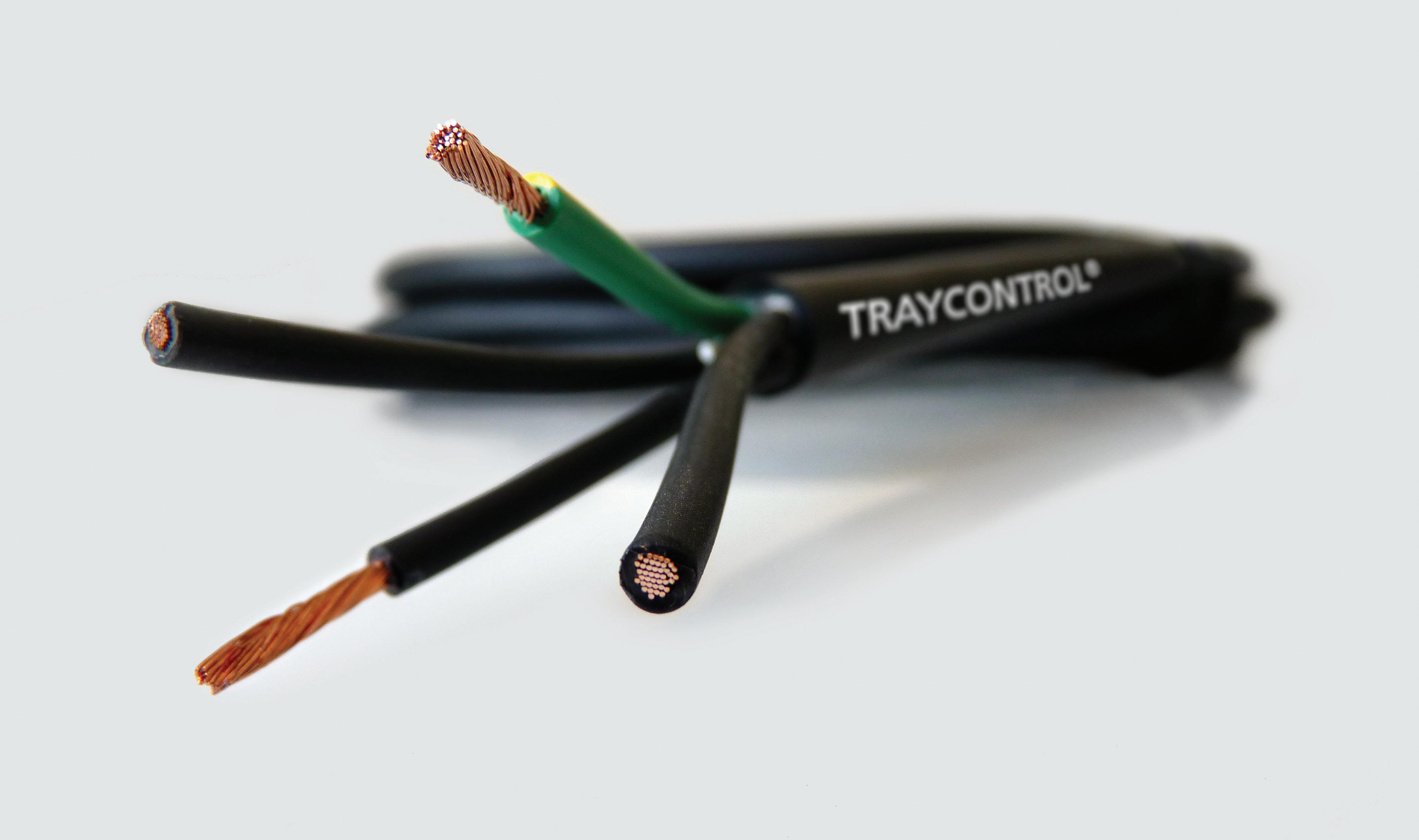
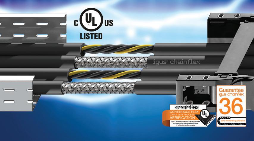
Standard cables typically manage 50,000 cycles, but a flexible cable can complete between one and three million cycles.
18 DESIGN WORLD — MOTION 8 • 2022 motioncontroltips.com | designworldonline.com HELUKABEL’S TRAYCONTROL PRODUCT FAMILY IS A VERSATILE, HIGHLY FLEXIBLE LINE OF INDUSTRIAL CONTROL, POWER AND INSTRUMENTATION CABLES CAPABLE OF BEING USED IN VARIOUS APPLICATIONS AND INDUSTRIES. Motion Systems Handbook
IN INDUSTRIAL CONTROL CABLES
Multi-axis machines and robots are always in continuous operation, featuring repetitive motions that can stress all the moving parts of the machine. Electrical data, power and signal cables — critical components in these designs — must be considered with care. Standard cables can fail prematurely, so it is necessary to select the right type of high-flex motion control cables for your industrial motion application. Designed and manufactured to cope with the tight bending radii and physical stress associated with motion applications, these highly flexible or continuous-flex cables have long service lives, especially if run inside protective cable carriers.
Flexible cables fall into two categories — those with conductors stranded in layers inside the cable and those with bundled or braidedCablesconductors.withstranded layers are easier to produce so usually less expensive. The cable cores are stranded firmly and left relatively long in several layers around the center and are then enclosed in an extruded tube-shaped jacket. In the case of shielded cables, the cores are wrapped up with fleece or foils. However, this type of construction means that during the bending process the inner radius compresses and the outer radius stretches as the cable core moves. This can work quite well because the elasticity of the material is still sufficient, but material fatigue can set in and cause permanent deformations. The cores move and begin to make their own compressing and stretching zones, which can lead to a corkscrew shape and even core rupture.
Flat cables o er compact design
An alternative to flexible cabling in some motion applications are flat cables. These cables can incorporate any variety of power, signal, and video conductors in a single compact cable. In addition to every type of electrical conductor, flat cables can also include tubing for air or liquids, and even fiber optics. By incorporating all these elements into a single flat cable, motion equipment can be significantly smaller, quieter, and more energy efficient. Flat cables are best for continuous flexing. Their wire conductors can individually flex in a single plane, which provides optimum flex life. Some motion control systems may encase separate wires, cables, and tubes in a carrier track to contain and manage the separate elements and to constrain their motion. These tracks are usually made of plastic and have a rather large bend radius. These tracks do not add performance to the motion device or machine, as they are simply cable management devices. Cable tracks can add bulk, mass and inertia to the motion system, and moving this extra mass requires more energy. While certain motion systems such as robotic applications may require this design, others may not and can use standard flat cabling instead to save weight and cost. Some flat-cable manufacturers offer cables
The other construction technique involves braiding conductors around a tension-proof center instead of layering them. Eliminating multiple layers guarantees a uniform bend radius across each conductor. At any point where the cable flexes, the path of any core moves quickly from the inside to the outside of the cable. The result is that no single core compresses near the inside of the bend or stretches near the outside of the bend, which reduces overall stresses. An outer jacket is still required to prevent the cores from untwisting. A pressure-fi lled jacket fi lls all the gussets around the cores and ensures that the cores cannot untwist. The resulting fl exible cable is often stiffer than a standard cable, but lasts longer in applications where it must constantly fl ex.

HELUKABEL is a global cable system solutions provider specializing in the production of cables, wires, cable assemblies, robotic dress packs, and drag chains. Our electrical solutions consistently and reliably bring power and transmit data to our customer’s applications in various automation-focused industries including machine building, automotive manufacturing, material handling, food and beverage, wood, pulp, and paper processing, oil and gas, and robotics. With a comprehensive product portfolio of more than 33,000 stock items, and the capabilities to design and build custom solutions, HELUKABEL is your one-stop source for electrical connection technology. HELUKABEL® USA, Inc. | West Dundee, IL | www.helukabel.com | sales@helukabel.com


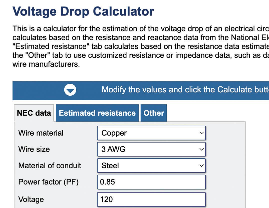
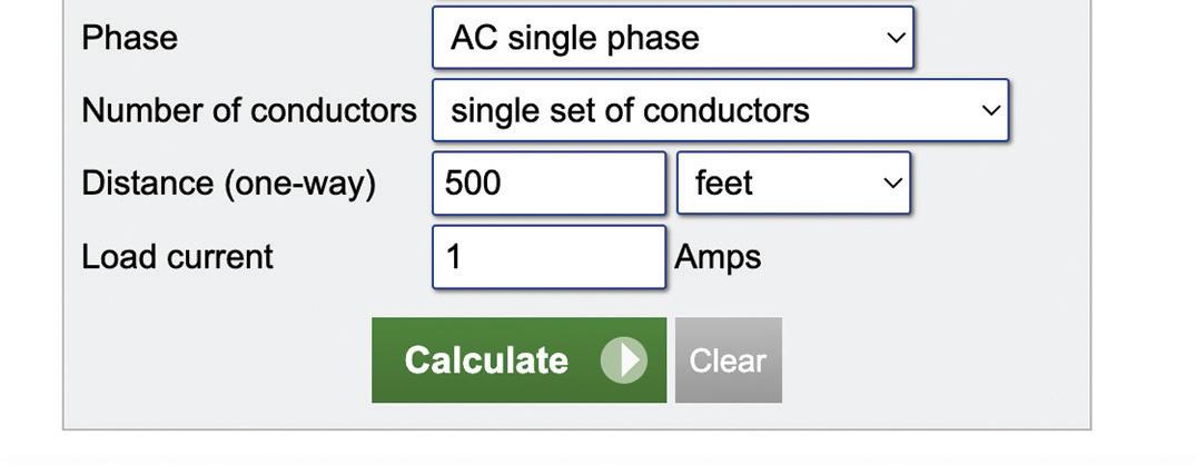
WHY SHOULD ONE WORRY ABOUT VOLTAGE DROP?
Motion Systems Handbook 20 DESIGN WORLD — MOTION 8 • 2022 motioncontroltips.com | designworldonline.com
Selecting the right cable Selecting the right cable for an application starts with fundamental parameters. First, determine whether the cable will be moving. Does the motion induce cable flexing or twisting? Or does the application induce flexing and torsion? Cables exist for all three situations.
If the application is only bending, determine the cable’s worst-case bend radius. Bend radius depends on the cable wire gauge and the kind of conductors in the cable. Cable size is determined by the gauge of wire which in turn is dependent on current requirements (and the number of conductors the application needs). As a general rule, finer conductor gauge allows tighter bend radii. Flat cables with PTFE jackets can have a larger bend radius than cables with silicone jacketing for a given number of conductors. For cabling in flexing applications, two key factors are wire conductors and the cable jacket. With continuous flexing, conductors containing multiple strands of fine-gauge wire generally last the longest.
To put it simply, excess voltage drop can reduce the operating efficiency of motors, lights, appliances, and other electrical equipment. If too much voltage is lost while passing through wires, equipment may not function properly, or at all. For certain equipment such as pumps, large motors, or machines that use compressors, even a small loss of voltage can be problematic. Keep in mind that voltage drop also generates heat, which can build up in wires or cables and damage the insulation, ultimately leading to safety issues such as fire and shock. Let’s take a look at the four main factors that affect voltage drop, and how to keep it to an acceptable minimum — defined by the National Electrical Code (NEC) as 5% at the furthest receptacle in a branch wiring circuit. For example, in a 120 V/15 A circuit, there should be no greater than a 6 V drop (to 114 V) at the furthest outlet, with the circuit fully loaded.
Chief environmental factors dictating the most suitable cable choice include exposure to harsh conditions such as temperature and humidity and required resistance to environmental contaminants such as oil or corrosive materials. For instance, what is the operating temperature for the application? Will the cables be in cold (freezing and below freezing) or hot environments? Will the cables need to endure exposure to oil? Here, other cables can resist full immersion for days. In the same way, cables also have varying degrees of flame resistance.
The most suitable choice of cable material depends on application needs, and can include PVC and halogen-free to Neoprene, rubber, silicone and other materials. Also, do the cables require electrical shielding? Tip: Consider any approvals that the cables may need to meet such as UL, CSA, CE, and RoHS.
When current passes through wire, it is pushed along by electrical potential, or voltage, which must exceed a certain level of opposing pressure from the wire itself. Voltage drop is defined as the amount of electrical potential loss that is caused by the contrary pressure of the wire. The four chief variables involved in voltage drop include the wiring material, diameter, and length, and the amount of current being carried. The current carrying capacity of a wire is often called ampacity, which stands for ampere capacity. With regard to the wiring material, copper and aluminum are widely used due to their excellent electrical conductivity and relatively low price compared with more expensive options such as silver or gold. Copper will experience less voltage drop than aluminum for the same wire length and diameter, as copper is a better conductor. Next, a larger wire size (diameter) will have less voltage drop than a smaller size of the same length. Wire length is also a key factor. A shorter wire will have less voltage drop than a longer wire of the same diameter. Finally, the amount of current being carried will affect voltage drop levels. An increase in current leads to increased voltage drop, but just how much depends on the wire’s ampacity, which in turn depends on variables such as wire material and temperature. One of the easiest ways to decrease voltage drop is to increase the size (diameter) of your wires or cables, which will lower the resistance of the overall wire length. Take into consideration that a larger copper or aluminum cable will add cost, so be sure to calculate voltage drop in order to specify a properly sized wire. Online voltage drop calculators and wire manufacturers are a good place to start.
MULTIFLEX 512-PUR UL/CSA, WITH OR WITHOUT A SHIELD FROM IGUS , IS A DRAG CHAIN-RATED CONTROL AND POWER CABLE SUITABLE FOR NOMINAL VOLTAGES UP TO 1,000 V (UL AWM). with silicone jacketing. These types of flat cables are durable and need no external armor for protection. They resist abrasion and will even self-heal minor nicks. Silicone encapsulation also provides protection against oils, acids, ozone, steam, and extreme temperatures.


The term “embedded motion” is most often used when referring to a motor that is an integrated part of the mechatronic system, rather than a separately coupled mechanism.
Of course, the right controller will always depend on the particular application needs.
A familiar type of controller is the programmable logic controller (PLC). These devices serve as the programmable smarts for a host of applications, from simple machine control up to advanced multi-axis motionThecontrol.nextstep in evolution beyond PLCs are programmable automation controllers or PACs. These industrial controllers combine the functionality of a PLC with the processing power of a PC. Note; because there is no industry-standard definition for a PAC the distinction between PACs and PLCs can be a bit fuzzy. For instance, higher-end PLCs now incorporate some of the features considered PAC territory. In fact, many PLCs now include standard programming languages, the ability to expand functionality through add-on modules, and connectivity to a range of the most common data bus systems.
Controllers are at the heart of every motion system, issuing motion commands to a motor or actuator. The controllers available to motion design engineers today are more powerful and offer better performance than ever before. Many of them feature built-in functions adaptable to a range of applications, making them more versatile. Typically, controllers are categorized in one of several ways. They can be divided by physical format (plug-in board, stand-alone, embedded) or by function (PLC, PAC, motion controller) or even by architecture (distributed vs. centralized.)
Spotlight on embedded control
Still, PACs differentiate themselves from PLCs by employing a more open architecture and modular design. They’re also more capable than PLCs at monitoring and controlling a large number of I/O, such as in a large processing plant or a complex automation system. They do this because data can be exchanged between devices and applications in different domains, such as motion and process control.
For example, standalone controllers are complete control units that include control circuitry, power supplies and external connections that mount to one physical enclosure. Such control units fit into machines in applications that consist of a single motion axis up to multiple axes of motion.
EMBEDDED CONTROLLERS FOR MOTION 22 DESIGN WORLD — MOTION 8 • 2022 motioncontroltips.com | designworldonline.com PACSYSTEMS RSTI-EP CPE 200 PROGRAMMABLE AUTOMATION CONTROLLERS (PAC) FROM EMERSON ARE HELPING DESIGNERS MINIMIZE THE NEED FOR SPECIALIZED SOFTWARE ENGINEERING. THE CONTROLLERS OFFER OPEN COMMUNICATIONS THROUGH NATIVE, PRE-LICENSED SUPPORT FOR OPC UA SECURE AND OTHER COMMON INDUSTRIAL PROTOCOLS FOR FLEXIBLE CONNECTIVITY OVER HIGHSPEED GIGABIT ETHERNET. IEC 61131 PROGRAMMING LANGUAGES HELP ENGINEERS WRITE AND RUN HIGH-PERFORMANCE ALGORITHMS FOR ADVANCED AUTOMATION FUNCTIONS.
Motion Systems Handbook
On the other hand, plug-in board controllers (sometimes called PC-based controllers) include a basic PC motherboard or ruggedized industrial PC as well as PCtype hardware components and a high-speed dedicated bus that transmits data to and from the processor. Inputs and outputs from the controller board provide interfaces to factory floor devices such as motors, actuators, and sensors and feedback.
Over the past several years, embedded solutions have found their way into the motion control space, with terms such as embedded motion, embedded motion control, and embedded motion controller now commonly used in product descriptions. Although there are no standard definitions for these terms, they all refer to some level of integration of motion control components for the purpose of making end devices better-suited for applications in which size, performance, and efficiency are paramount.

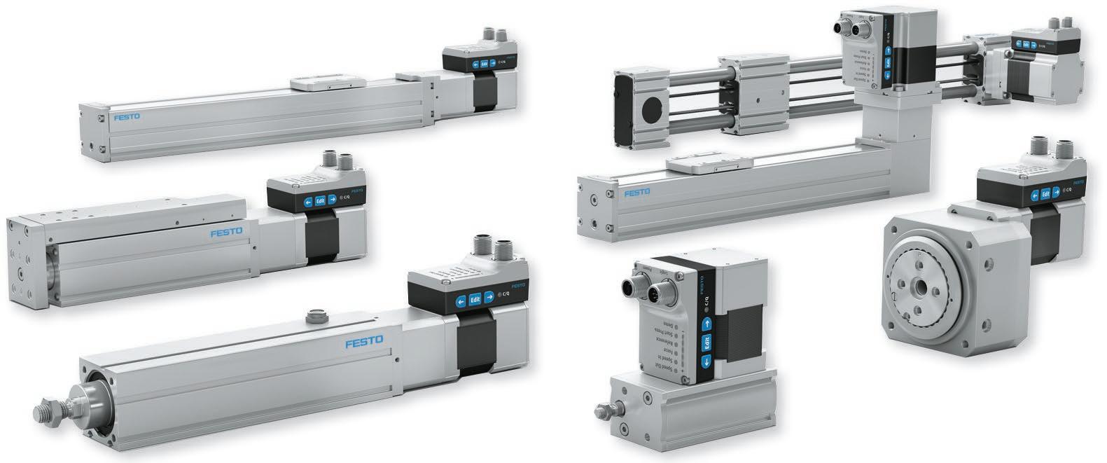
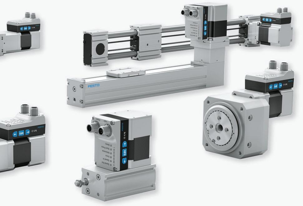
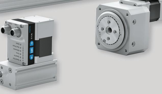
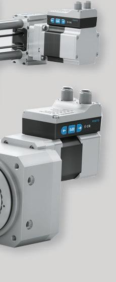
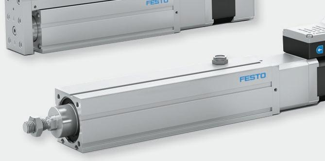
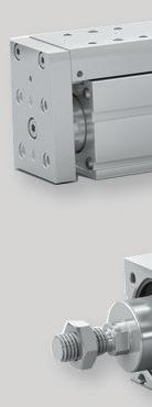
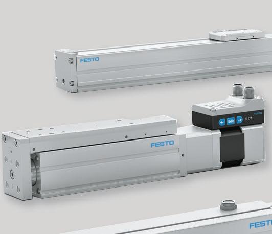
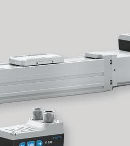
• Quick and easy commissioning using the integrated buttons on the motor or via IO-Link
• Simple control with 2 digital inputs for basic functions or enhanced control with IO-Link for additional functions, multi position download with speed and torque data festo.us 23DESIGN WORLD — MOTION Controllers
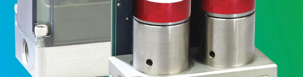
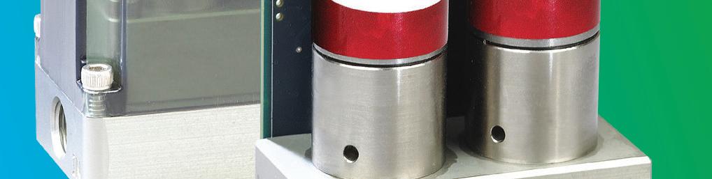
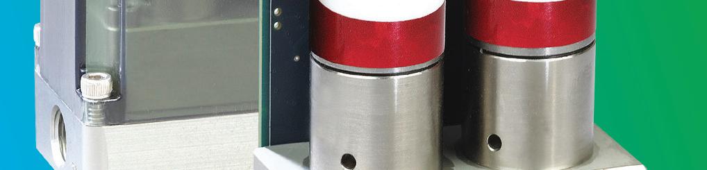
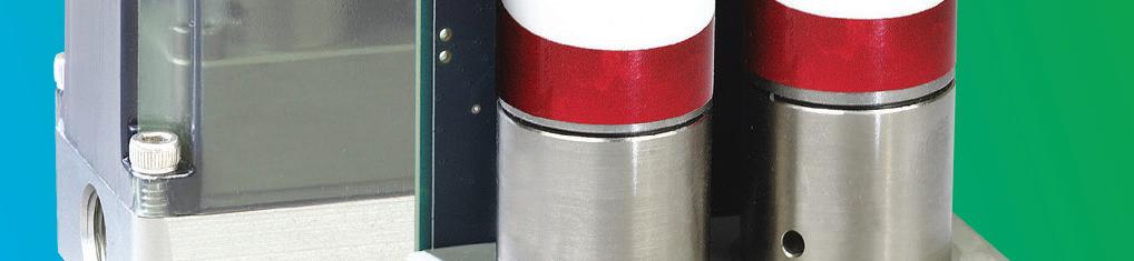
The Simplified Motion Series axes are ideal for simple positioning and pressing/clamping movements.
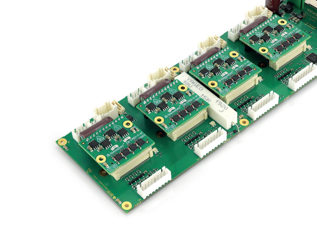
THE CM-CPB3-44 ETHERCAT CONTROLLER FROM NANOTEC CONTROLS FOUR BRUSHLESS DC OR STEPPER MOTORS WITH A RATED POWER OF UP TO 150 W PER AXIS. FEEDBACK ON THE MOTOR POSITION IS PROVIDED BY HALL SENSORS OR INCREMENTAL OR SSI ENCODERS. FEATURES SUCH AS FIELD-ORIENTED TORQUE, SPEED AND POSITION CONTROL, COMBINED WITH OTHER FEATURES SUCH AS ACCELERATION FEEDFORWARD AND JERK-LIMITED RAMPS, ENSURES OPTIMUM DYNAMIC PERFORMANCE AND CYCLE TIME.
Looking for cost effective and energy efficient positioning?Thesimplicity of pneumatics combined with the advantages of electric automation
• Connection via IO-Link for enhanced functionality including diagnostics
For example, frameless motors (sometimes referred to as “kit” motors) can be integrated into a robot joint, with the load directly coupled to the motor or even integrated into the motor itself. Embedded motion reduces the number of transmission components required, which in turn provides higher efficiency and reliability. And in many cases, the drive and control electronics are also integrated into the end device, rather than being mounted remotely on the machine or in a separate control cabinet. Where embedded motion commonly refers to the mechanical part of the motion system (the motor), the term “embedded motion controller” typically refers to PCB-mounted motion control modules that are integrated directly into the machine. These modules take care of all motion controller functions, such as servo path planning and motion profile generation. The primary benefit of an embedded motion controller is that the system no longer requires remote-mounted drives and PLCs (or other controllers), significantly reducing the length of encoder and feedback cables between the motor and the controller. This means less wiring, better signal integrity, fewer failure points, and better machine performance.
The term “embedded motion control” refers to an embedded system that includes the mechanical devices (motor, actuator); sensors or encoders; motion control hardware, software, and firmware; and a network interface. In other words, embedded motion control combines mechanical and electrical components and functionality into one device that has been optimized for size, performance, and efficiency. Because they’re purpose-built (rather than general purpose, like a PLC or industrial PC), embedded controllers and embedded motion control systems significantly reduce development time and simplify programming, allowing designers to focus on the specific motion application and how it operates within the system, rather than designing the motion system from scratch.


a range of shapes and sizes to accommodate the many diverse uses they can be put to. For instance, conveyor widths can range from less than 2 in. for moving extremely small parts to several feet wide for handling boxes in packaging applications.
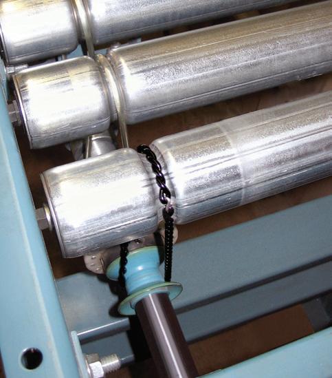
A common type of conveyor drive setup is based on timing belts. Timing-belt conveyors use toothed belts that engage synchronous drive pulleys while serving as the conveyor surface as well. These provide excellent belt movement control for accurate part or fixture positioning.
Conveyors are usedsystemsto deliver bulk or discrete materials through processing operations or along assembly lines. Advances in materials, controls, and modular subcomponents have spurred advancements in conveyor systems including new large conveyors for bulk material transport, miniature conveyors for discrete sorting, and a host of other Conveyorsinnovations.comein
When designing a conveyor, one of the first considerations is the conveying media to be used, which depends on the size, shape, CONVEYORS TAKE CENTER STAGE motioncontroltips.com | designworldonline.com exceed rated load, speed, or acceleration, and the product can move, or slip, on the belt during starts and stops or any time there’s a change in acceleration. Also referred to as synchronous or toothed belts, timing belts have toothed surfaces that engage with matching, toothed pulleys. This positive engagement between belt and pulley, together with pre-tension (force applied to the belt in the direction of motion) eliminates the problem of belt slipping. And timing belt conveyors typically use belts that are reinforced with steel or Kevlar tensile cords to provide increased load carrying capability and enable high acceleration rates (which result in high forces on the belt) without causing the belt to stretch. To improve grip, the top (carrier) side of the belt can be coated to increase friction between the product and the belt surface and reduce the possibility of the product slipping on the belt. Belt and pulley materials and finishes can also be selected to meet specific application requirements and environmental conditions, such as ESD-compatible, foodgrade, or clean environments.
BELT-DRIVEN
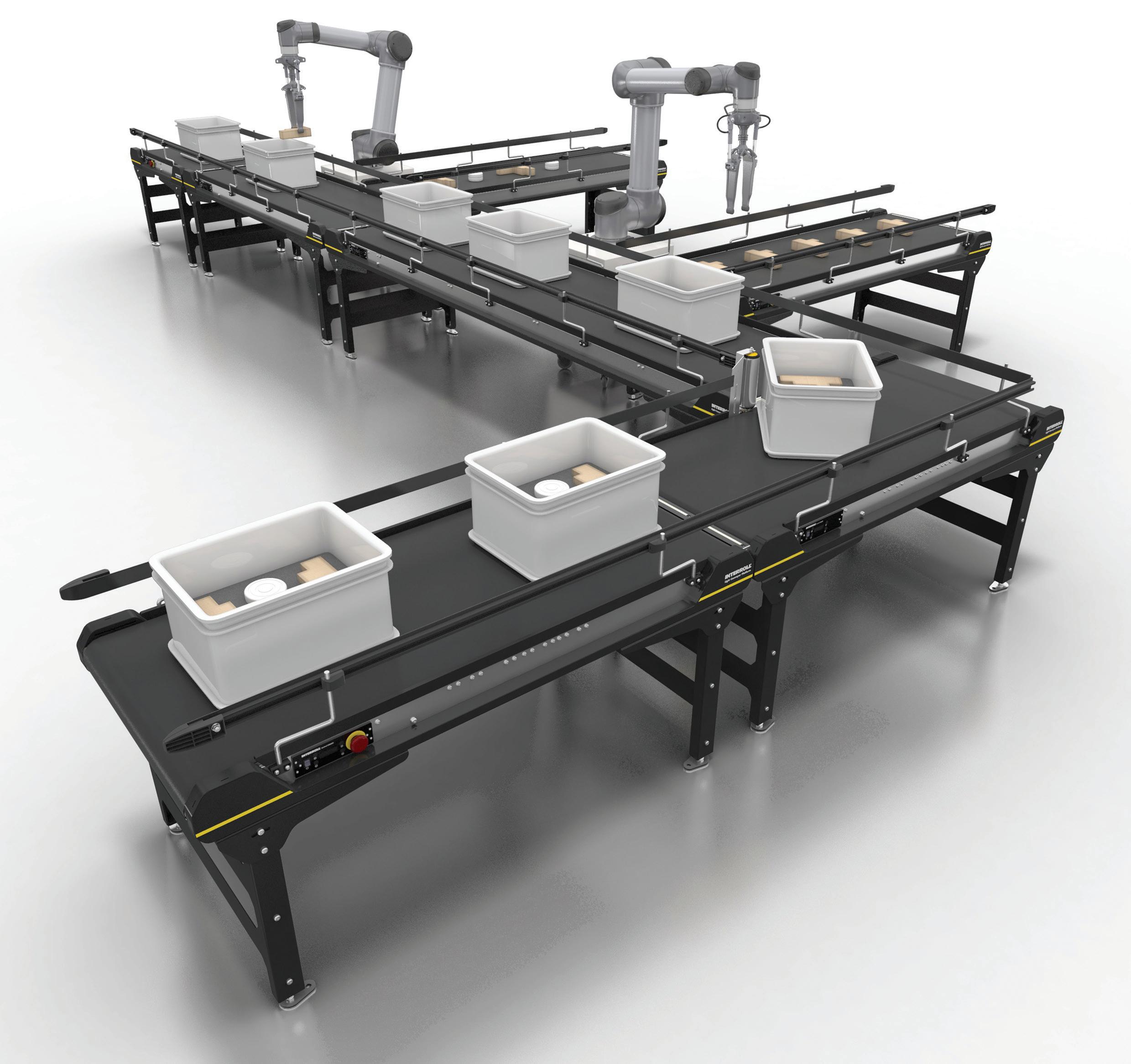
INTERROLL’S LIGHT CONVEYOR PLATFORM (LCP) IS DESIGNED TO TRANSPORT SMALLER CONVEYED GOODS, AS WELL AS BOXES OR POLYBAGS WEIGHING UP TO 50 KILOGRAMS. THE SYSTEMS ARE DESIGNED TO INCREASE PRODUCTIVITY OF PRODUCTION CELLS AS WELL AS ASSEMBLY AND PACKAGING STATIONS THROUGH EFFICIENT MATERIAL FEED AND DISCHARGE. and weight of the product being handled and on the process requirements, such as conveying distance and route, transport speed, and positioning accuracy. For assembly and automation applications, the most common conveying media are belts, chains, flat-top chains, and powered rollers. Of these media choices, belts are arguably the most versatile. They can be manufactured in virtually any width and can span long conveying distances, and they operate with lower noise and less required maintenance than chains or rollers. Belts and their mating rollers (or pulleys) are also available in many different materials and finishes to meet specific application requirements and environmental conditions.
Most conveyors in light to medium duty discrete transport applications use belts that wrap around two or more pulleys. A motor powers the pulleys that in turn engage the conveyor belt. A range of styles and materials are available to meet specific applications. Some belts are low friction, so products can slide a bit for accumulation. In contrast, highfriction belts have more grip to better hold products to the belt. One of the most common types of conveyors are belt-driven. Here, servo drives can accurately start and stop belt conveyors to provide precise part location. They also let engineers control acceleration and deceleration, and thus are most suitable for conveyors used in assembly operations. Manufacturers often mount encoders to a conveyor’s drive shaft to sense shaft rotation or count pulley revolutions for accurate control of the belt in feeding or indexing applications. Single drive, multi-belt conveyors are set up to run off of a single gearmotor or driveshaft of coupled shafts. In some arrangements, the belts even mount to a single conveyor frame.
Focus on timing belt conveyors
24 DESIGN WORLD — MOTION 8 • 2022
Traditional belt-driven conveyors use flat belts that rely on friction between the belt and rollers to transmit power. They also rely on friction between the belt surface and the product to hold the product at a specific location on the conveyor. This friction-based design is flexible and economical, but it leads to a potentially variable product positioning and orientation. Case in point; the belt can slip on its drive rollers if working conditions
Motion Systems Handbook
When application requirements call for accurate product location with no loss of position, cleats or fixtures can be attached to the belt carrier surface to hold the product in a specific location and with the correctAnotherorientation.option to ensure precise location and orientation is to transport the product on a pallet. Locating the product on a fixed pallet, together with the accurate, no-slip conveying of the timing belt, provides the highest level of position accuracy and certainty.
mk’s
| info@mknorthamerica.com Recirculating Over-Under Conveyors Streamline Over-Under
No
25DESIGN WORLD — MOTION Conveyors
| Faster Deliveries
www.mknorthamerica.com/SPU better products. better solutions. (860)
PALLET
Some key industry trends are shaping conveyor technology as well. For instance, the push to automate assembly, distribution operations, and material handling are leading to innovations in conveyor design, as is the drive for more energy-efficient designs in general.
A further benefit of timing belt conveyors is that the movements — and, therefore, the products being carried — of multiple conveyors can be synchronized. This makes timing belt designs ideal for dual- or multipleline configurations and allows large, heavy loads to be transported, even when accurate positioning is required.
Applications with
Units | Less
Other conveyor types
These conveyors are used to move work piece pallets from one assembly station to another.
In terms of conveyor technology, systems based on belt and roller designs are the most common, with pallet conveyors gaining ground. These conveyor types consist of individual pallets on conveyors that typically hold a single product. The conveyor itself is belt driven with a dc motor and they are smart in that they can be controlled individually, which also eliminates accumulation of products on a conveyor belt. Some conveyors for pallet handling include a basic timing belt or roller-chain conveyor. 769-5500 Conveyor the SPU 2040 from mk North America, Inc. SPU 2040 conveyor system is a powerful alternative to traditional over-under conveyor systems. Vertical Transfer System Controls
One of the things that differentiates this style of conveyance from a traditional large diameter roller or flat belt conveyor is the ability to easily add additional components and devices to further manipulate the work piece pallet. Typical applications involve some type of orientation change to the work piece pallet as it moves about the system. Another common task is to precisely locate the work piece pallet for a robotic application. CONVEYORS, SUCH AS THIS EXAMPLE FROM GLIDE LINE, SHOWS THE COMPONENTS IN THE DRIVE MECHANISM INCLUDING THE MOTOR AND GEARBOX DRIVING THE BELT DRIVES ON BOTH SIDES OF THE CONVEYOR WITH THE PALLET ON TOP.


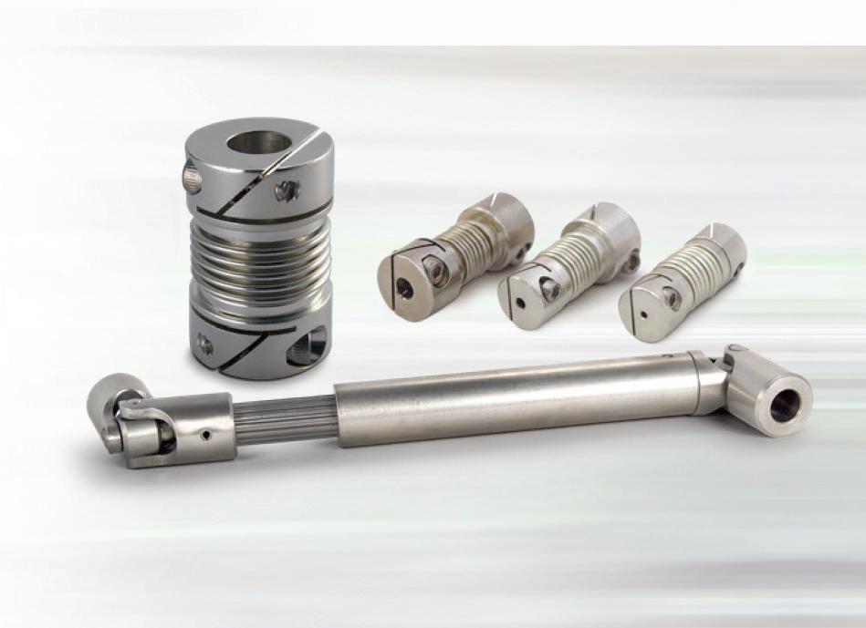
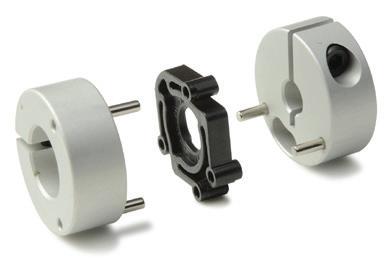
STEEL DISC COUPLINGS LIKE THESE FROM RINGFEDER PROVIDE BACKLASH-FREE TORQUE TRANSMISSION AND EXCELLENT POSITIONING ACCURACY IN MACHINES THAT INVOLVE SYNCHRONOUS OPERATION, FREQUENT STARTS AND STOPS, OR REVERSING OPERATIONS.
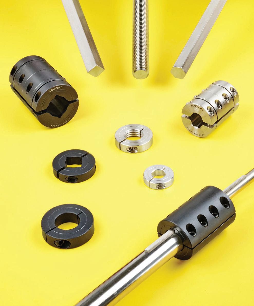
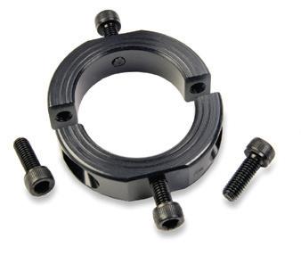
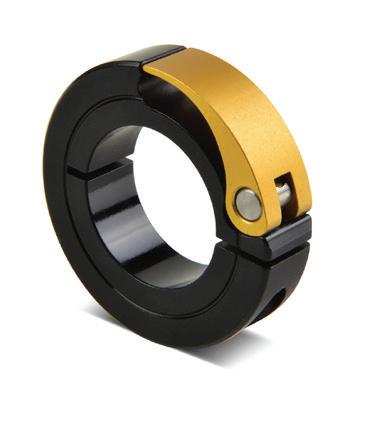
SHAFT COLLARS AND COUPLINGS, LIKE THESE FROM STAFFORD WITH DIFFERENT BORES, ARE OFTEN AVAILABLE IN STANDARD INCH AND METRIC SIZES FROM 1/8 TO 10-IN. I.D. (COUPLINGS TO 6-IN. I.D) TO PRECISELY MATCH DIFFERENT SHAFTS AND POSITIVE DRIVE SYSTEMS.
Environmental considerations include moisture, temperature, chemicals, and vacuum — all important things to consider at the time of selection. The question to ask yourself is “What are we dealing with in all these different issues?” For example, an aerospace application where engineers are using a coupling to control the aperture on a telescope. In this situation, a coupling that can survive the vibration of an actual spacecraft during takeoff would be necessary. motioncontroltips
Motion Systems Handbook
Additionally, other factors like handling the vacuum of space, extreme temperatures, and no outgassing would need to be examined. In this specific example, Ruland chose 316 stainless steel Oldham hubs and a special non-outgassing PEEK Oldham
AtemperaturesaForinexampleAnotherinsert.applicationwouldbeacouplinganautoclave’senvironment.anapplicationlikethis,couplingmustsurvivehighforshortintervals.bellowscouplingmightbean option, but autoclave temperatures will often exceed the temperature capability of the epoxy in the Oldham. To work around this, an Oldham coupling with a PEEK disk might work. The disk not only does not outgas, but it can also withstand high temperatures.
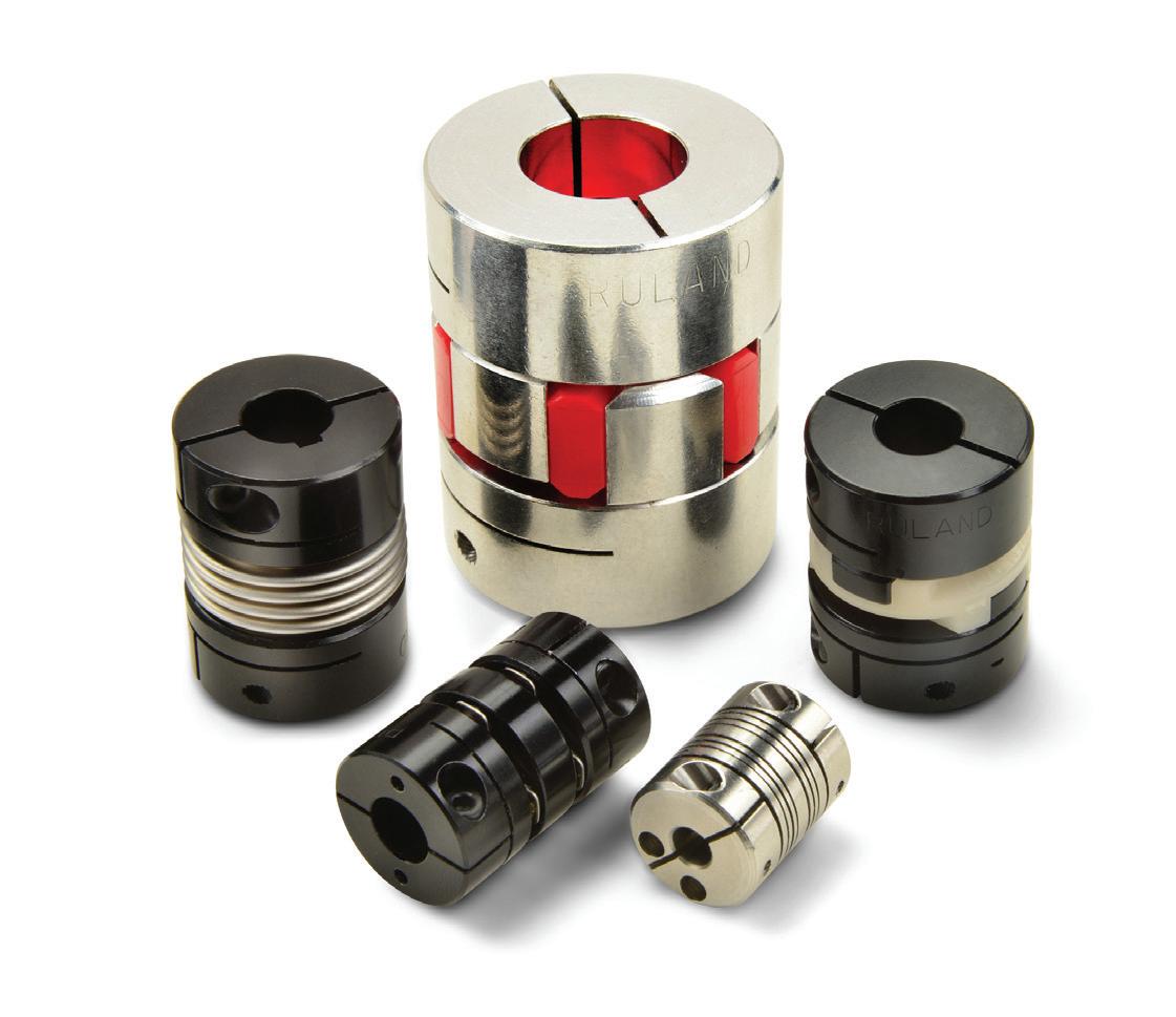
Couplings are motion system devices that connect two shafts and are found in countless motion systems. Mechanical couplings are often found on rotating equipment like motors to transmit several motion parameters. These parameters include the transmission of angular positioning, velocity, and torque. Here, we look at a few of the most frequently asked questions about mechanical coupling selection fundamentals and more.
Certain applications are relatively easy to solve with most any coupling at 5,000 or even up to 10,000 RPM. Occasionally, couplings may get up near 25,000 RPM or even higher — 75,000, 80,000 RPM. The consideration engineers need to factor in is not just torque capacity but how well balanced the coupling is for the type of speed they expect the coupling to encounter. If the coupling is not either balanced or symmetrical by nature, a vibration problem is likely because of the imbalance of the weight. This is an important and often overlooked consideration. As positioning devices accelerate faster and faster, coupling balance is more important than ever.
Windup Often confused with backlash, windup is easy to overlook when selecting couplings for a motion system. But windup is an important consideration that can cause real problems if not factored in early in the design process. Windup and backlash are often confused. They are not the same. Windup is dampening. It’s dampening or cushioning. It is not an error in the coupling — It’s not “play.” A jaw coupling provides a perfect example of windup: The spider compresses, rebounds, and absorbs shock and dampens — that’s wind up, not error. Some couplings have different amounts of wind up. A bellows coupling or disc coupling, for example, has little windup. They have high torsional stiffness. Rigid couplings have almost no windup. Windup is a good thing to have in your coupling design. Especially for applications where frequent shock loads are expected and a jaw coupling has been selected. Windup is your friend at that point in the jaw coupling. Duty cycle Duty cycle is a critical but often overlooked consideration during the coupling selection process. Essential elements like types of motion, potential shock load scenarios, and start/stop situations should all be evaluated when selecting a coupling for your next motion systemDutyapplication.cycle,types of motion, continuous start/stop and reversing, and asking, “how often is the system running?” These all come into play with selection. Selection error often occurs when the type of motion is not accounted for or when the number of cycles is not understood. Talk to the manufacturer and give them your duty cycle. A system running at full speed, that does not stop or reverse abruptly, will often have a jaw coupling selected for the application. Gradual
Speed
Temperature The environment where the coupling will operate is one of the first questions to be answered when selecting a coupling for an application. Understanding the myriad environmental variables a coupling might encounter is crucial during the early design stages of your motion system.
COUPLING SELECTION FUNDAMENTALS 26 DESIGN WORLD — MOTION 8 • 2022
.com | designworldonline.com
Coupling selection fundamentals

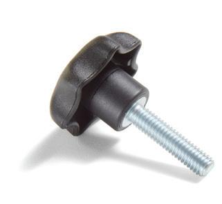
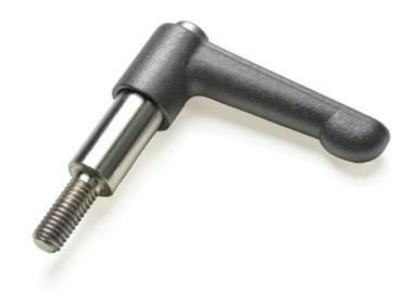
TOOL-LESS ADJUSTMENT COMPONENTS • Adjustable handles and knobs replace standard hardware and can be used to torque components without tools. • Levers can be used with Ruland shaft collars for quick installation and adjustment. MODULAR MOUNTING SYSTEMS • Assortment of components that allow users to build small assemblies for mounting sensors, conveyor rails, machine guards, and more. • Optional pre-designed kits make it easier to select the right system for your application. UNIVERSAL JOINTS • Widest selection in the industry: over 3000 standard single and double universal joints to start your next design with. • Available from Ruland in 2 weeks or less for the shortest lead times in the industry. • Yokes, pins, and blocks are precision machined, ground, and selectively heat treated for smooth operation at high operating angles. Ruland Manufacturing is proud to support the FIRST Robotics Competition as a Gold Supplier of precision shaft collars & couplings.SLIT AND CONTROLFLEX COUPLINGS • Slit couplings are available in short and long styles giving designers a variety of body sizes to choose from to t application envelope and performance requirements. • Control ex is a highly exible encoder coupling designed for applications with high speed, low torque, and wide differences in shaft sizes (up to a 4:1 small to large ratio). • Slit couplings are available in bore sizes from 1.5mm to 12mm (1/8” to 1/2”) and control ex couplings are available in sizes from 6mm to 40mm (1/4” to 1-1/2”). QUICK CLAMPING COLLARS • Hand operated: no tools required to install, remove, & adjust. • Best suited for systems that require adjustments.application.frequent All products available directly on RULAND.COM www.ruland.com | sales@ruland.com MOUNTABLE SHAFT COLLARS • Available with OD ats and holes for direct mounting of the collar to other components. • Proprietary manufacturing processes ensure superior t, nish, and holding power. • Manufactured in a variety of sizes, styles, and materials.NEWWHAT’S RULANDfrom Adjustable Handle Star Knob Shaft Collar with Lever Slit Coupling Control ex Coupling
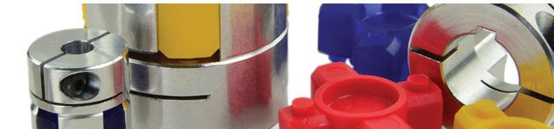


MECHANICAL COUPLINGS ARE OFTEN FOUND ON ROTATING EQUIPMENT LIKE MOTORS TO TRANSMIT SEVERAL MOTION PARAMETERS. THESE PARAMETERS INCLUDE THE TRANSMISSION OF ANGULAR POSITIONING, VELOCITY, AND TORQUE. OF RULAND
| COURTESY
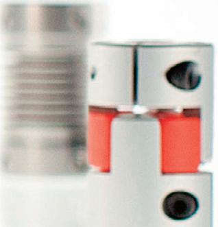
In that type of application, beam couplings are common. When asking for increased dampening, choose a jaw Dampeningcoupling.application examples where there are different materials available —different hardness of material to change the dampening characteristics — are common in food processing OEM applications. What are slit couplings?
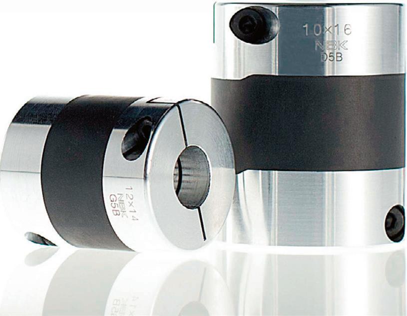
28 DESIGN WORLD — MOTION Motion Systems Handbook yourMaximizeperformance with the widest range of precision couplings NBK® www.nbk1560.com 307 East Church Road, Suite 7, King of Prussia, PA 19406 phone: 484-685-7500 fax: 484-685-7600 e-mail: info.us@nbk1560.com BOOTH 134043
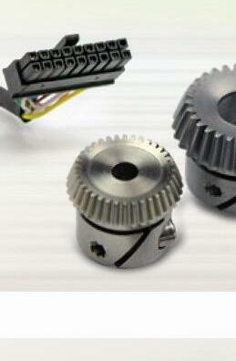
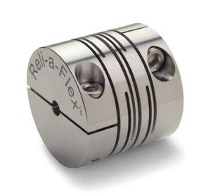
Slit couplings are mechanical couplings and can offer zero-backlash, reduced weight, and are manufactured with intermittent slit cuts, making them a good starting point for designers of robotic systems. While they are visually similar to multiple beam couplings, the slit cut design gives them higher torque and torsional stiffness capabilities and numerous length options in the same outer diameter, allowing coupling performance to be tailored to system requirements. Slit couplings have torque comparable to a single disc coupling, torsional stiffness like a stainless-steel beam coupling, and misalignment consistent with an aluminum beam coupling. This combination of specifications allows a slit coupling to be used in place of one of these styles, which all have limitations such as no accommodation of parallel misalignment in a single disc coupling. Along with low mass and inertia, these characteristics make slit couplings a good choice for robotic systems. Robotic applications such as those found in medical, surgical, factory, and warehouse environments often require a zero-backlash coupling with high torque, torsional rigidity, and speed. These robots can start, stop, and reverse constantly, necessitating a responsive coupling. Along with other performance benefits, slit couplings have a moderate amount of dampening, which is useful in robots requiring vibration control, such as material handling and articulating robots.
start/stop — systems running at full speed then slowly coming to a stop or reverses — often have beam couplings. Beam couplings can work well in these applications. Many of the coupling types like the bellows type, and in most cases the disc types, are also used, however. This gradual start/stop cycle is a must for coupling life because they can’t handle the hard stop and start shock loads. For dampening, frequent starts and stops, or high shock load applications, the applications may require a coupling that can dampen the impulse load; again, jaw couplings are a good option. Selection error occurs when this is not accounted for.


DESIGN WORLD ONLINE EVENTS AND WEBINARS Check out the DESIGN WORLD WEBINAR SERIES where manufacturers share atheir experiences and expertise to help design engineers better understand technology, product related issues and challenges. WEBINAR SERIES FOR UPCOMING AND ON-DEMAND WEBINARS, GO TO: www.designworldonline.com/design-world-online-events-and-webinars

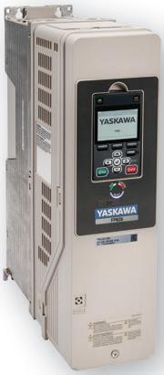
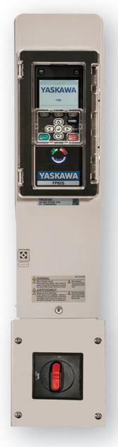
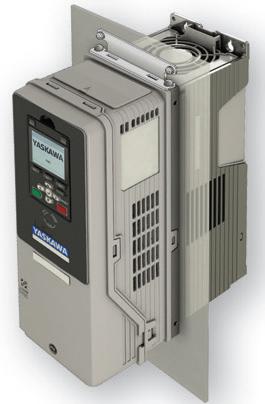
Yaskawa America, Inc. 1-800-YASKAWA Email: info@yaskawa.com | yaskawa.com PUMP PRODUCTIVITYUP MAKE THE COMPLICATED SIMPLE You will get pumped up when you take a look at Yaskawa’s FP605 industrial fan & pump drive. The FP605 is a versatile drive that saves time and resources on installation and programming, while maximizing efficiency for peak energy savings and the return on your investment. • Enclosure options: IP20/UL Type 1 or IP55/UL Type 12 • Narrow footprint for side-by-side mounting • Induction, PM and synchronous reluctance motor control • Supports all major industrial network communications • Pump control features that maximize drive and pump life • Mobile-friendly setup with optional Bluetooth keypad • Programmable without main power supply connected Need to optimize your industrial fan and pump operations? Call Yaskawa today at 1-800-927-5292, FP605 INDUSTRIAL FAN & PUMP AC DRIVE w/SwitchIP55/ULType12IP55/ULType12IP20/ULType1 Type Backside12Flange IP20/UL IP55/UL IP55/UL For more information, https://go.yaskawa-america.com/yai1436visit:


Spotlight on VFDreflected waves
Inductance is a conductor’s resistance to change in electric current, and capacitance is the ability to store an electrical charge. Both are impeding mechanisms and present an opposition to current when voltage is applied. The collective impedance caused by inductance and capacitance is known as reactance. Additionally, when the voltage pulses reach the motor, they encounter a different (higher) impedance than in the cable, causing the pulses to be reflected back to the drive. Under certain conditions, a pulse from the VFD can add to a pulse reflected back from the motor, resulting in a doubling of the voltage level. The greater the length of the cable (i.e. the distance between the motor and the VFD), the greater the over-voltage, or reflected wave.
Drives are generally split into dc and ac. One of the most common type of ac drives are variable frequency drives (VFD). VFDs operate by switching output devices on and off, which can be transistors, IGBTs (insulated gate bipolar transistors), or thyristors. VFDs can be either constant voltage or constant current, with constant voltage types being more common. They use pulse width modulation (PWM) to control both the frequency and the voltage applied to the motor.
Drives
Most VFDs today operate via PWM, with the inverter producing a continuous train of pulses rather than sinusoidal wave forms. These voltage pulses are transmitted to the motor terminals through the motor cable. The cable’s inductance (a factor of impedance) is proportional to the length of the cable. High inductance, due to long cable lengths, increases the amount of time it takes to charge the capacitance of the motor, which increases the amount of energy in the cables.
In motion control systems, drives are the interface between control signals and an electric motor, delivering the signals in the form of voltage and current that cause the motor to move. Sometimes drives are referred to as amplifiers because they amplify the voltage signals that come from the controller, which are too low to drive sufficient current through the motor windings to cause meaningful speed or torque. Modern digital drives have internal processing capabilities that allow them to not only manage position, velocity and torque loops but also take over high-level functions such as trajectory generation. Digital drives also allow tuning to be done via software, and they’re able to monitor internal functions and provide fault diagnostics.
Together with cable length, the rise time of the switching device also has an effect on reflected waves and the amount of voltage overshoot. If the turn-on time of the switching device is slow, the capacitance of the motor has time to charge and discharge in step with the switching device. But if the switching device’s turn-on time is fast, the voltage
First, their quick switching time (also referred to as rise time, or dV/dt) means lower energy losses, which allows for less cooling and smaller designs. IGBTs also permit the VFD to use a higher carrier frequency for sending output voltage pulses to the motor, which reduces audible motor noise and provides the motor with reduced harmonics and lower peak current. Lower peak current enables the motor to run cooler and develop more torque-producing current throughout the speed range.
MANY ENVIRONMENTS.
Causes of reflected waves
Reflected waves, also known as transmission line effects or standing waves, are over-voltages that can damage the motor and cable. The use of IGBTs in variable frequency drives has helped to improve VFD performance in several ways.
On the flip side, IGBTs have brought to light the phenomenon of reflected waves. Also known as transmission line effects or standing waves, reflected waves are over-voltages that can damage motor insulation and cables.
One of the reasons why VFDs are becoming more common are for their energy savings. By controlling the amount of current drawn by the motor, energy costs can be decreased due to the motor not running at full load all of the time. This is especially important as motor efficiency and energy savings become top design priorities. VFDs also provide an advantage on motor start-up. For motors operated without a VFD, an induction motor on start-up has to handle a high initial in-rush current. As the motor speeds up and approaches a constant speed, the current levels off from the peak in-rush values. With a VFD, the motor’s input starts off with low voltage and a low frequency, avoiding the problem of high in-rush currents. Eliminating the in-rush currents upon start-up also gets rid of the excessive torque on components, increasing the life of the motor and reducing maintenance costs and the need for repair.
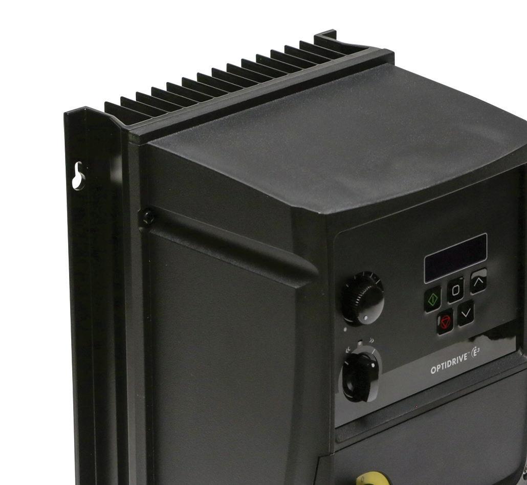
VFD S, LIKE THIS MODEL FROM BISON, SIGNIFICANTLY REDUCE ENERGY CONSUMPTION BY ENABLING ELECTRIC MOTORS TO OPERATE AT LESS THAN FULL SPEED. SUCH NEWER MODELS ARE ALSO DESIGNED TO BE EASY TO COMMISSION AND OPERATE. THIS PANEL-MOUNTED VFD IS OUTDOOR-RATED, WASHDOWN-READY AND DUST-TIGHT, MAKING IT SUITABLE FOR
FOCUS ON VARIABLE FREQUENCY DRIVES 31DESIGN WORLD — MOTION8 • 2022motioncontroltips.com | designworldonline.com detailed
The most effective way to prevent the occurrence of reflected waves and overvoltage is to keep the cable length shorter than manufacturer’s recommended maximum. In cases where reducing the cable length isn’t feasible, there are hardware solutions, such as output reactors, filters, and terminator devices, that can reduce or eliminate reflected waves, protecting the motor and cable from damage.
Motion Systems Handbook 32 DESIGN WORLD — MOTION applied across the cable increases, and more energy is stored, resulting in a higher over-voltage.
Precision Motion. Made Easy.
THE SCHEMATIC SHOWS THE ELECTRICAL LAYOUT OF A TYPICAL VARIABLE FREQUENCY DRIVE, WITH 3-PHASE INPUT AT LEFT, THE BRIDGE RECTIFIER AND FILTER SECTION, FOLLOWED BY THE INVERTER SECTION AND THE PWM OUTPUT TO THE MOTOR.
E ects of reflected waves
Aerotech’s Automation1 motion control platform powers some of the most precise processes in operation all over the world. Yet, it is very simple to use and easy to integrate. Reduce your risk with the variety of software, controller and high-performance drive options available with Automation1. Make your precision motion easier at aerotech.com/automation1
The problem with reflected waves is that the voltage spikes can ionize the air in the air gap between motor windings, as well as the air between the cable insulation and cable jacket, causing partial discharge, or corona. The point at which this ionization causes arcing across the motor windings (or across the conductors in the cable) is known as the corona inception voltage (CIV). When the motor CIV is reached, the insulation in the motor windings can be damaged or even fail. When the cable CIV is reached, a short-circuit can occur and the cable can be permanently damaged. Although reflected waves can occur regardless of the type of switching device—IGBT, GTO (gate turn off), or BJT (bipolar junction transistor)—the fast switching capability (rise time) of IGBTs makes this phenomenon more prevalent. Case in point: current IGBTs have turn-on times as fast as 0.1 msec, where BJTs switch at 0.5 to 1.0 msec, and GTOs switch at 15.0 to 20.0 msec. Damage due to reflected waves is more prevalent with 460-V and 575-V IGBT-based drives. Drives that operate on 230 volts are rarely damaged due to voltage overshoot because the reflected waves have amplitudes that are lower than the motor CIV.
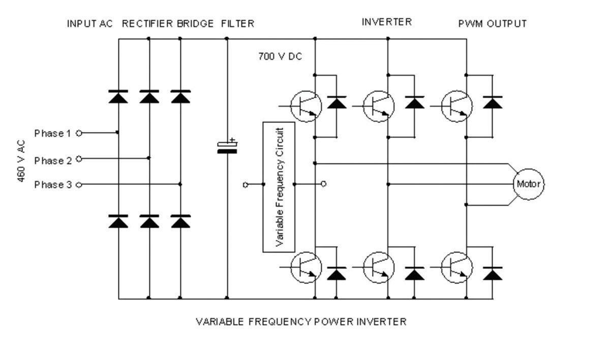


We’ve covered several different magnetism-based linear-sensor technologies in past Design World Motion Handbooks … and one induction-based variable-reluctance linear sensor (VR sensor) type as well — that of LVDTs. In fact, there are several other types of linear sensors based on induction. Two that are particularly common in motion applications are: Linear variable-reluctance transducers (LVRTs) — another VR sensor type — and differential variable-reluctance transducers (DVRTs) along with related variations on traditional LVDTs
Linear-variable-inductance transducers — also called LVITs These linear sensors actually track inductance variations — disturbances made by a conductive target through a magnetic field. The latter is made by primary winding transformer that’s been energized … sans permanent magnets needed with magnetism-based linear sensors. LVRTs resemble LVDTs but include a continuous core winding and not a segmented winding as in LVDTs. In contrast, LVITs contain an inductive sensing coil connected to onboard sensor electronics. Upon axis traversal, a conductive cylinder called a spoiler coupled to the axis’ end effector travels axially through the coil — in turn changing the inductance and prompting the sensor electronics to generate an output signal proportional to axis’ move.
Most design involvedengineersinmotion system engineering are intimately familiar with the function of induction motors. Most are also familiar with proximity sensors that use induction for metalobject presence detection. But there’s a third design leveraging induction for its operation. Called inductive linear sensors, these use field induction (in a conductive subcomponent) for linear-motion feedback.
LINEAR SENSING BASED | COURTESY OF VLADIMIR TIMOFEEV 33DESIGN WORLD — MOTION8 • 2022motioncontroltips.com | designworldonline.com
ON INDUCTIVE TECHNOLOGY Encoders & sensors

Another induction-based technology There are also more sophisticated technologies based on inductive operation and advanced electronics to offer OEMs accuracy, speed, and reliability exceeding those of other linear-sensing options. In one proprietary design, the physics described in both Ampère’s law and Faraday’s law are put to work. Conductive sine and cosine-patterned traces are manufactured onto a circuit board. 90° phaseshifted alternating current on these traces function as a coil to generate twin fi elds perpendicular to the traces’ 2D plane. An active position marker (which attaches to the moving carriage or component of the motion axis — but needs no external wiring) passes over the traces. Summing the resulting signal yields: H · sin(x) · cos(w·t) + H · cos(x) · sin(w·t) = H · sin(w·t + x) Where x = Marker position t = Time and w = Applied waveform frequency H = Signal strength. In other words, the phase of the signals’ sum at each location is proportional to marker position x Amplitude is modulated along the travel, and sin(w·t) is the reference signal. First the electronics phase shift the Motion Systems Handbook Your Responsive Experts IN MOTION CONTROL USA–BASED We design & manufacture our Accu-Coder®, Accu-CoderPro®, and Tru-Trac® encoders to ISO 9001:2015 standards in-house at our headquarters in Idaho, USA. WE’RE HERE TO HELP EPC’s engineers and encoder experts are here to answer your most technical questions. Contact us today. 1-800-366-5412 · encoder.com Contact us We’ll help you find the right motion feedback solution for your application. Contact us today. AMPÈRE’S LAW RIGHT-HAND RULE MAGNETIC FIELD FROM CURRENT = = Line integral of B around a closed path = Permeability of free space = Current CONDUCTIVEWIRE SOLENOIDMAGNETICFIELD AMPÈRE’S LAW STATES THAT A CURRENT THROUGH A CONDUCTOR CAUSES A PROPORTIONAL MAGNETIC FIELD AROUND THAT CONDUCTOR.

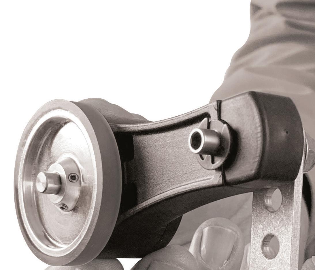


Finally, the sensor electronics compare the phase information with the reference signal. The marker returns summed signals back to the circuit board; tracking phase shift between outgoing and returned sinusoidal signals produces a dc voltage proportional to their phase shift — which serves to inform motion controls of the marker’s positional change.
HOLLOW SHAFT KIT ENCODERS Designed for Drives, Robot Joints Slim, Open-Center Form Factor for Simple Integration Wiegand Energy TechnologyNo Batteries Required! Absolute and Multiturn Insensitive to Dust & Factory-FriendlyMoistureAssemblyTolerances www.posital.com 35DESIGN WORLD — MOTION8 • 2022 Encoders & sens s first signal 90° to get the second with sin(w·t + 90°) = cos(w·t). Then the addition theorem is applied, and amplitude information is converted into phase information: sin(w·t + x) = sin(w·t) · cos(x) + cos(w·t) · sin(x)
SPOILER BASICLINEARINDUCTION-BASEDTRANSDUCER INDUCTIVECOIL ELECRONICS ONE LVIT VARIATION INDUCTION-BASEDPROPRIETARYTRANSDUCER 45° 225° 135° 360° 270° 315° POSITIONMARKER NO MATTER THE PERMUTATION — SIMPLE TO SOPHISTICATED — INDUCTIVE LINEAR-SENSOR TECHNOLOGIES ARE WEAR-FREE AND INHERENTLY IMMUNE TO EXTERNAL MAGNETIC EFFECTS.
In another patented variation, linear sensors employing this technology integrate both transmission and receiver coils on a common circuit board protected by a ruggedized housing. During operation, the position marker receives an alternating field from the transmission coil. In response, the marker induces current in the receiver coil … a current that varies with location.
Receiver-coil sine and cosine structures include coarse and fine tracks for both approximate and high-precision position tracking. The position marker’s position is reflected in the signals’ phase relationship — converted to a usable position signal by the linear sensor’s electronics. 0° 180° 90°


BESIDES STROKE LENGTH, ANOTHER IMPORTANT FACTORS FOR SELECTING SENSOR OR ENCODER INCLUDE
Motion Systems Handbook Superior encoders for position and motion control With a comprehensive line up of encoder solutions, Renishaw brings the expertise needed to address your manufacturing challenges. Whether your application calls for optical, magnetic or laser technology, our encoders achieve the highest levels of accuracy, durability and reliability. Powerfully positioned for innovative motion control. See us at: IMTS Booth2022135509 www.renishaw.com/encoders usa@renishaw.comRenishaw Inc., West Dundee, IL 60118 © 2022 Renishaw Inc. All rights reserved. Your partner for manufacturinginnovative Despite what is essentially electromagnetic operation, these induction-based linear sensors are immune to external magnetic fields — including EMI from electric motors and inverters. That’s because they operate within an exceptionally narrow frequency range and reject any signals at frequencies outside that tight range. That also avoids the problems associated with sensing components that rely on magnetic markers (such as magnetostrictive sensors) that can collect metal shavings during normal operation ... as in machine-tool and assembly settings, for example.
More sophisticated linear-feedback components based on inductive measurement are readily programmable, as the microprocessor electronics for deriving position from marker-induced signals can also accept programmable settings. These include status reporting as well as customizing the electrical measurement range, slope, and positions for minimum and maximum output voltages and currents.
THE APPLICATION’S REQUIREMENTS FOR LINEAR POSITION-SENSOR OUTPUT TYPE — WHETHER ANALOG (0 TO 20 mA, 4 TO 20 ma , OR 0 TO 10 V) OR DIGITAL.
A LINEAR-POSITION

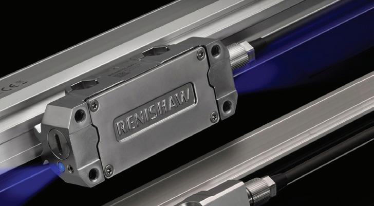


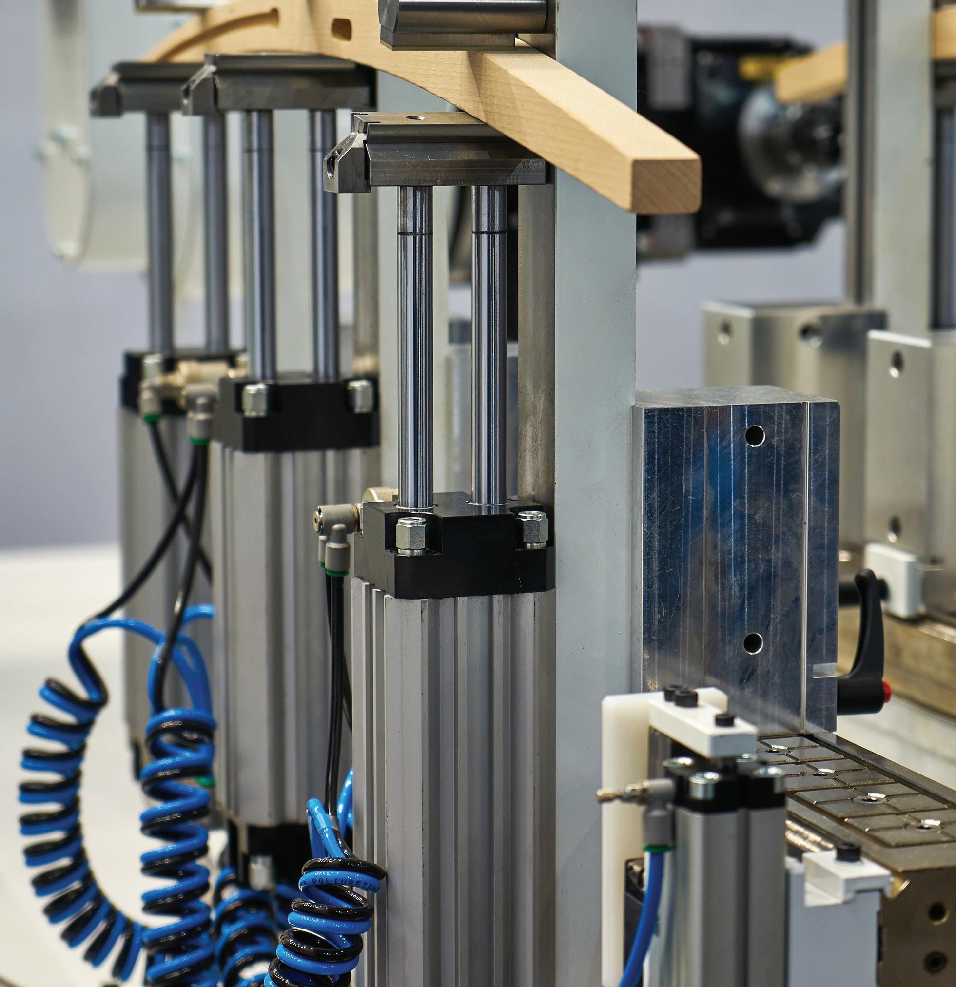
One common solution is to include a clutch or brake in the assembly to prevent large inertial loads from driving the gearmotor backward through axis backlash … or forward after de-energization.
Another common solution is the employ drives and controls capable of electronic compensation to prevent such backdriving and overrunning, which can otherwise damage gearmotors as mentioned … as well as attached system components and workpieces. Sudden or erratic and large peaks in torque called shock loading present similar modes of potential gearmotor damage. Such loading is in some cases unavoidable: After all, punches, presses, and extruders subject their components to necessarily powerful strokes during normal operation; professional-grade crushers and power tools must sometimes power past temporary obstacles and jams; debarking, grinding, and chopping axes must sometimes drive through unusually dense material volumes; and hoists and conveyors must sometimes
CONSIDERING GEAR GEOMETRIES,|COURTESYOFNIKONAFT 37DESIGN WORLD — MOTION8 • 2022motioncontroltips.com | designworldonline.com Gears & gearmotors INERTIA, AND USUAL LOAD CONDITIONS
Note however that these load types differ from the rapid stops or reversals that can damage most gearmotors … especially inertial-load plug reversals — rapid switches in rotational direction sans intermediate stopping. That’s why properly designed gearmotor axes will either:
The limits of a gearmotor include those related to unusual loads, load arrangements, and duty cycles. Durability and (gear) strength ratings are the limiting factors when a gearmotor is subject to cyclical loads.
• Bring attached loads to a full stop before reversing or • Will fully disengage load attached to the gearmotor before such changes.
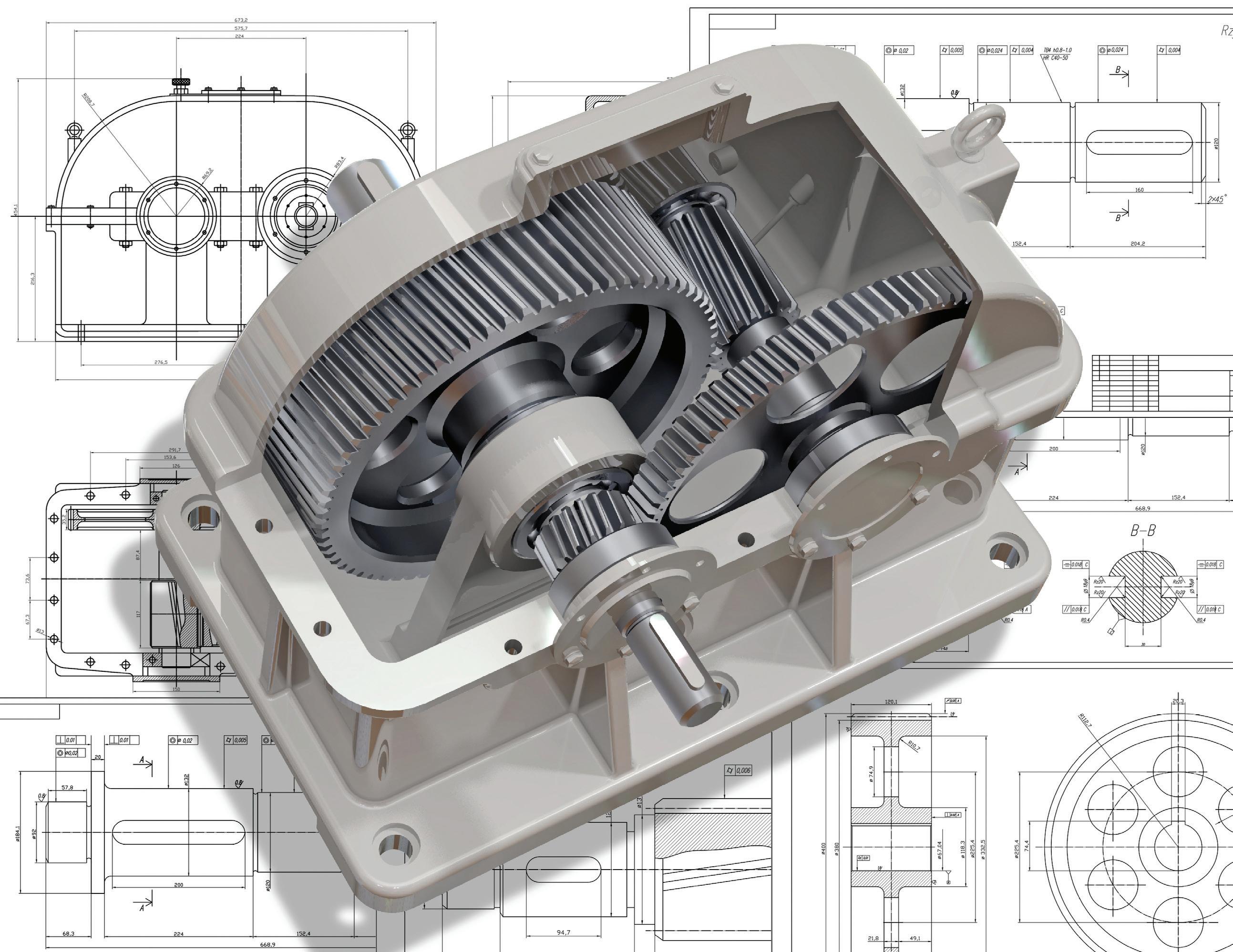
CGI Motion standard products are designed with customization in mind. Our team of experts will work with you on selecting the optimal base product and craft a unique solution to help di erentiate your product or application. So when you think customization, think standard CGI assemblies. Connect with us today to explore what CGI Motion can do for you. copyright©2021 cgi inc. all rights reserved. YOUR CUSTOM SOLUTIONS ARE CGI STANDARD PRODUCTS Advanced Products for Robotics and Automation 800.568.GEAR (4327) • www.cgimotion.com
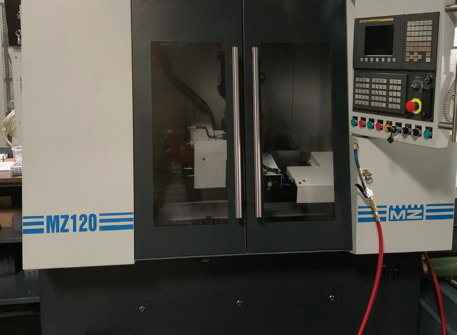


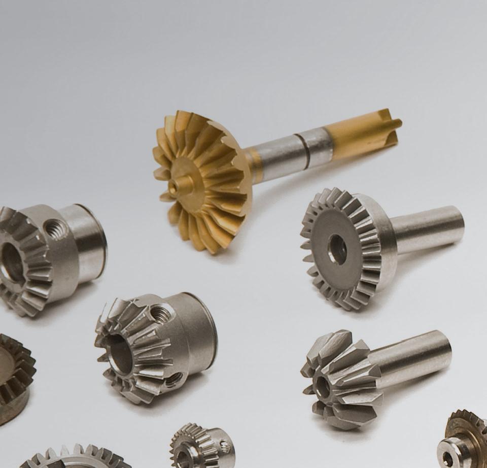

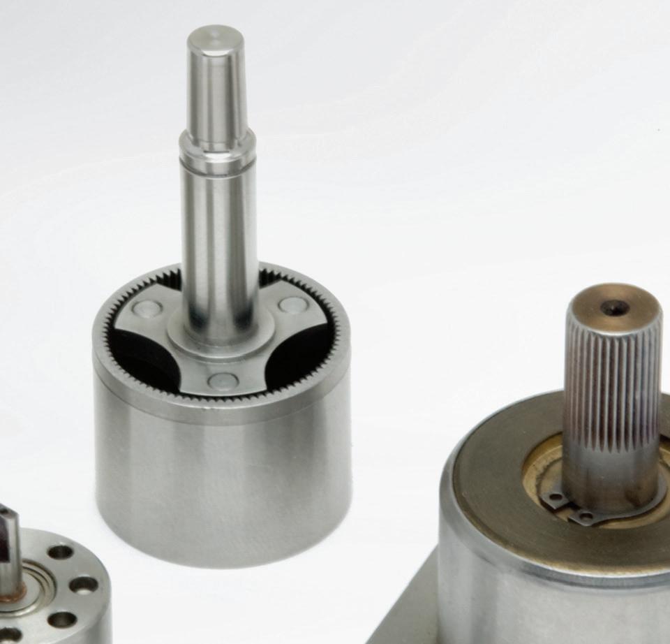


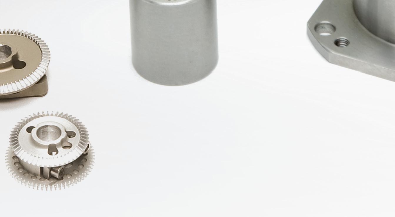


On the other hand, if the motor’s inertia significantly exceeds the load’s inertia, it’s likely that the motor is oversized. That in turn has negative implications throughout the system — including higher initial cost, higher operating cost, larger footprint, and the need to oversize other components such as mounting hardware, couplings, and cables. If the inertia ratio is too high, the load inertia is much higher than the motor inertia and will cause problems with positioning accuracy, settling time, or control of velocity or torque.Ifthis is the situation at hand, load inertia
In this context, the inertia to which we’re referring is mass moment of inertia, sometimes called rotational inertia — an object’s resistance to change in rotational speed. An object’s mass moment of inertia depends on its mass and geometry … usually the radius defined by the object’s center of mass and the point around which the object rotates. If the load’s inertia significantly exceeds the motor’s inertia, that load will essentially try to drive the motor … and the motor will struggle to get the load to its target position, speed, or torque. That in turn will prompt the motor to draw higher current … which decreases efficiency and increases wear on the motor and electrical components.
• (Less commonly) the payload itself
39DESIGN WORLD — MOTION8 • 2022motioncontroltips.com | designworldonline.com HIGH-TORQUE GEARBOXMOTOR PAIRING | COURTESY OF STEFAN11 Gears & gearmot s overcome sudden additions of payload — as when unexpectedly large products are dropped on conveyances, for example. Shock loading is generally quantified by its severity as well as its switching duty — the frequency with which the torque peaks occur. Most gearmotor manufacturers publish figures on maximum gearmotor shock-loading capabilities according to a grading system or as a percentage of running load. For example, a heavily ruggedized unit may be capable of withstanding shock that is 300% greater than the typical continuousrunning load for the axis. However, especially challenging inertia ratios and duty along with significant shock-load conditions (as well as shock-amplifying mechanical components such as chain in the drivetrain) can often necessitate further upsizing of the gearmotor.
• Shaft misalignment, often addressed with the addition of a flexible coupling Overhung loading can cause detrimental bending in the gearmotor output shaft — necessitating resistance to this force by both the shaft itself as well as its support bearings. In fact, any mechanical belt, cable, or chain drive directly mounted on the gearmotor’s shaft will exert some bending force. Mounting such drives as close as possible to the gearmotor body helps minimize the effects of overhung load on the bearings and shaft. Overhung load Ō can be calculated:Where T = Torque; r = Radius of mechanical output-shaft component; and x = Power-transmission adjustment factor.
Using gearing to optimize mot -system inertia rati Any system using a motor to drive a load with precise positioning, velocity, or torque requires consideration of inertia. That’s because the ratio of load inertia to motor inertia significantly impacts a motor’s ability to effectively and efficiently control attached loads. That’s especially true during the acceleration and deceleration portions of the motion profile.
In some rating systems, the latter is unity for chain drives, 1.3 for timing-belt drives, and 2.5 for flat-belt drives. Once the (unavoidable) overhung load requirement for a given axis is calculated, the design engineer should consult overhung-load limits in charts supplied by gearmotor manufacturers ... or communicate the details of the overhung load during the specification process.
Yet another extenuating condition is that of overhung loads — those which occur when some load exerts a perpendicular force (or hangs off) a gearmotor’s output shaft. These loads can be: (Most commonly) attached powertransmission components (including cable, belt-drive pulley, or chain sprocket)
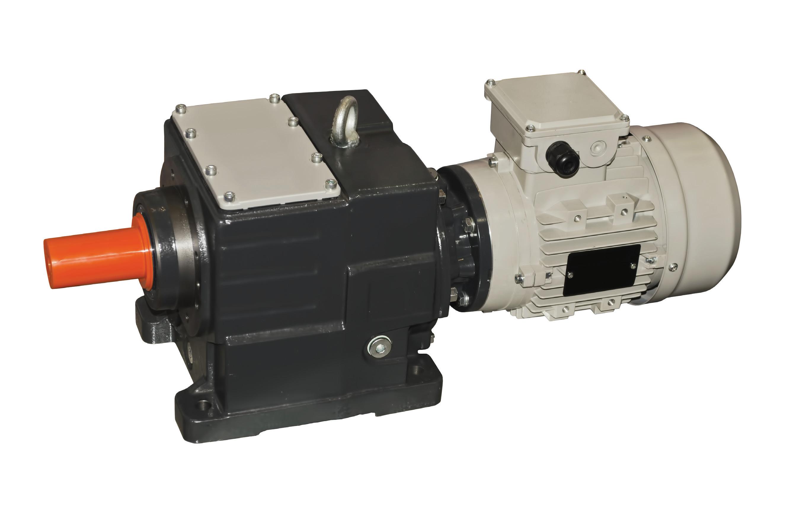
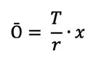
Although it is possible to use a gearbox or gearset that is configured to reduce torque (and increase speed) in motion control applications, a more typical solution here is to choose a smaller motor.
Gearmotor: This complete motion component is a gear reducer integrated with an ac or dc electric motor. Usually the motor includes the gears on its output (typically in the form of an assembled gearbox) to reduce speed and boost available output torque.
Special requirements for servogearing Servo systems are precision-motion setups with feedback and (in most cases) stringent accuracy demands. So for these designs, engineers should pick servogear reducers with good torsional stiffness, reliable output torque, and minimal backlash. OEMs tasked with integrating servo systems should look for quiet reducers that easily mount to the motor and require little or (if possible) no maintenance. In fact, advanced machinery often integrates servogears into application-specific electromechanical arrangements … and several of these arrangements are common enough to have specific labels. Here is a look at some of the most widespread.
Note that the inertia of the gearset or gearbox JG is added to the load inertia, but its effect is typically small compared to the reduction provided by the gear ratio.
Engineers use gearmotors in machines that must move heavy objects. Speed specifications for gearmotors are normal speed and stall-speed torque.
Gearbox: This is a fully integrated mechanical component consisting of a series of mating gears contained in a housing with shafts and bearings (to support and resolve loads) and in many cases a flange for motor mounting.
Gearhead: Most of the motion industry makes no differentiation between the terms gearhead and gearbox. But in a few contexts, the term gearbox specifically refers to housed gearing as described above while the more general term gearhead also refers to assemblies of otherwise open gearing that installs within some existing machine frame.
40 DESIGN WORLD — MOTION 8 • 2022 Motion Systems Handbook that is seen by (reflected to) the motor can be decreased by adding a gearset or gearbox between the motor and the load: Where JL = Inertia of the load reflected to motor and JM = Inertia of the motor. Adding a gearset or a gearbox to a motor-driven system reduces the load inertia by the inverse square of the gear ratio, meaning that even a relatively low gear ratio can have a significant effect on the inertia ratio: Where JL = Inertia of load reflected to motor; JD = Inertia of drive — whether ball screw, belt, or rack-and-pinion set; JE = Inertia of external (moved) load; JC = Inertia of the coupling; JG = Inertia of gearset or gearbox; and i = Gear ratio.
Other open gearing simply mounts to the electric-motor output and operates exposed to the environment. Some such open gearing is self-lubricating — constructed of dimensionally stable polyamides or similar materials engineered to meet stringent cleanliness, vibration, weight, and cost requirements.
In addition to optimizing the load-motor inertia ratio, gearboxes are often used in motion control applications to increase the torque delivered to the load from the motor, but they also decrease the rotational speed delivered to the driven component from the motor, by an amount equal to the gear ratio. Therefore gearboxes are often called gear reducers or speed reducers.
The latter are often targeted to compact, consumer-grade, or battery-powered mobile designs necessitating especially tight integration and omission of potentially redundant subcomponents. In one variation, a series of parallel plates might support gear-train shafts (and bearings) and allow bolting to a motor face.
In other words, if a motor running at 1,200 rpm is driving a load through a 3:1 gearbox, the rotational speed delivered to the load will be 1,200 ÷ 3 = 400 rpm. This reduction in speed can enable the system to operate at a more favorable location on the motor’s speed-torque curve.

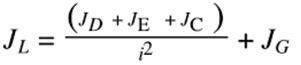

www.gamweb.com/linear | info@gamweb.com | 888.GAM.7117 Build your own Cartesian System with GAM Linear Mount Products Everything Between the Motor and the Actuator Parallel mounting kits save space by mounting the motor parallel to the ballscrew Parallelactuatormounting EPL-U Inline gearbox with hollow or shaft output and custom adapter for easy mounting to linear actuators WDS Bellows style distance couplings connect actuators additionalwithoutshafts DL-DC Right angle Dyna-Lite gearbox with hollow output design for easy mounting to linear actuators. Includes output adapter tailored to the actuator GSL Theta axis with zero-backlash strain wave gearbox includes output flange or thru-hole for tooling and integrated motor mount Simplify the process of designing and building your own Cartesian systems with GAM’s Linear Mount Products Choose from a variety of inline and right angle gearboxes that connect directly to actuators, along with the necessary mounting adapters and couplings, to transform individual products into an integrated solution.®
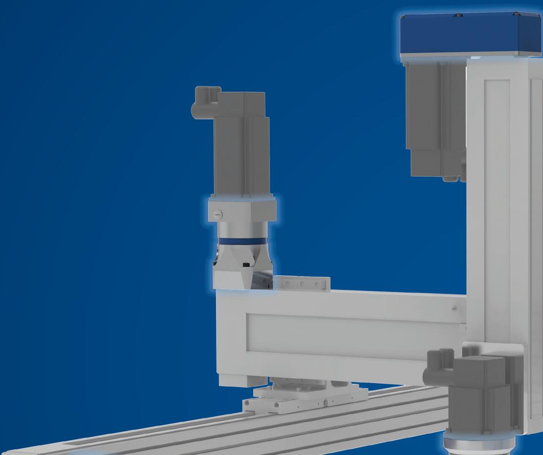


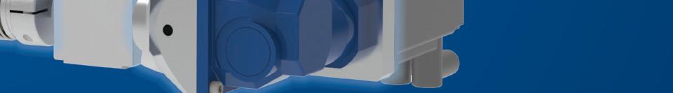

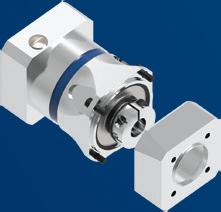
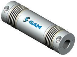
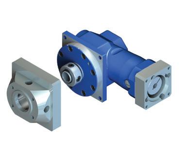

42 DESIGN WORLD — MOTION 8 • 2022 motioncontroltips.com | designworldonline.com PLANETARY GEARSET | COURTESY OF JACEK JĘDRZEJOWSKI
More on planetary gearsets
Planetary gearsets offer several advantages over other gearsets. These include high power density, the ability to get large reductions from a small volume, multiple kinematic combinations, pure torsional reactions and coaxial shafting. Another advantage to planetary gearbox arrangements is power-transmission efficiency. Losses are typically less than 3% per stage, so rather than waste energy on mechanical losses inside the gearbox, these gearboxes transmit a high proportion of the energy for productive motion output. Planetary gearbox arrangements distribute load efficiently, too. Multiple planets share transmitted load, which greatly increases torque density. The more planets in the system, the greater load ability and the higher the torque density. This arrangement is also very stable due to the even distribution of mass and increased rotational stiffness. Disadvantages include high bearing loads, inaccessibility and design complexity. In servo systems, besides boosting output torque, gearboxes impart another benefit — reducing settling time. Settling time is a problem when motor inertia is low compared to load inertia … an issue that’s the source of constant debate (and regular improvement) in the industry. Gearboxes reduce the reflected inertia at the controls by a factor equal to the gear reduction squared.
Motion Systems Handbook GEARMOTORS DRIVE CONVEYORS IN A WIDE ARRAY OF LOGISTICS APPLICATIONS. | COURTESY OF NORD DRIVESYSTEMS
More on hypoid gearsets
Particularly common in servo systems, planetary gearsets consist of one or more outer planet gears that revolve about a central sun gear. Typically the planet gears mount on a movable arm or carrier that rotates relative to the sun gear. The sets often use an outer ring gear, or annulus, that meshes with the planet gears. The gear ratio of a planetary set requires calculation, because there are several ways they can convert an input rotation to an output rotation. Typically, one of these three gear wheels stays stationary; another is an input that provides power to the system, and the last acts as an output that receives power from the driving motor. The ratio of input rotation to output rotation depends on the number of teeth in each gear and on which component is held stationary.
Hypoid gearboxes are a type of spiral bevel gearbox — with the difference that hypoid gears have axes that are non-intersecting and not parallel. In other words, the axes of hypoid gears are offset from one another. The basic geometry of the hypoid gear is hyperbolic rather than having the conical geometry of a spiral bevel gear. In a hypoid gearbox, the spiral angle of the pinion is larger than the spiral angle of the gear, so the pinion diameter can be larger than that of a bevel gear pinion. This provides more contact area and better tooth strength, which allows more torque to be transmitted and high gear ratios (up to 200:1) to be used.

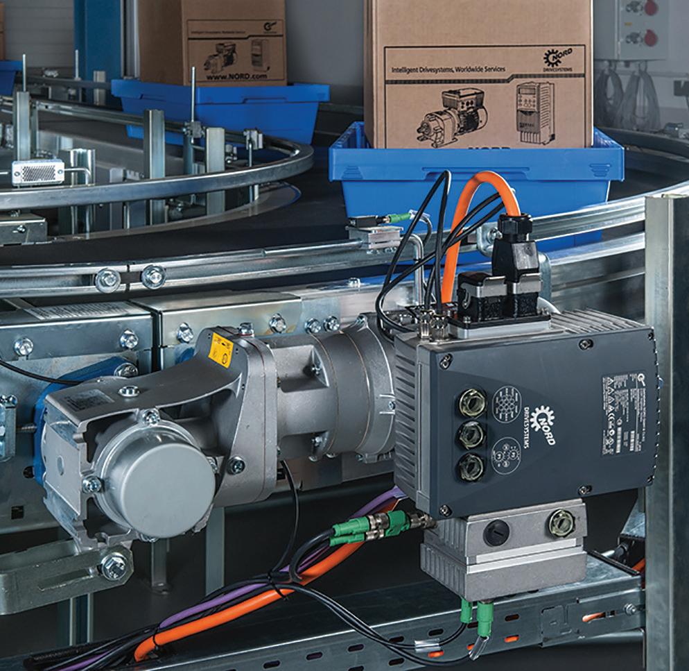
toComponentsMotionAutomateanyIndustry 800-363-2145 diequa.com/dw Right Angle Precision Servo Gearheads with Single or DUAL Output Options

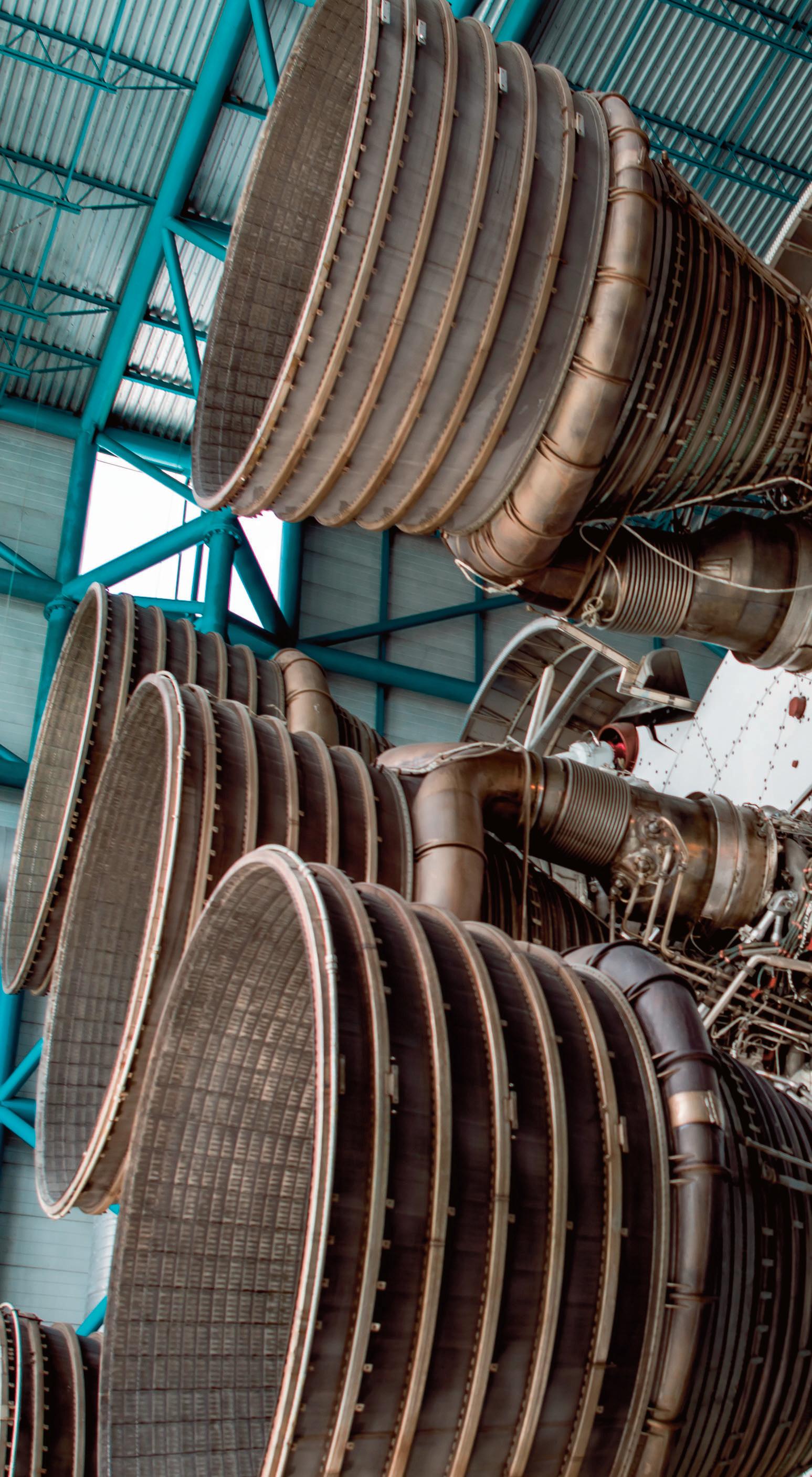
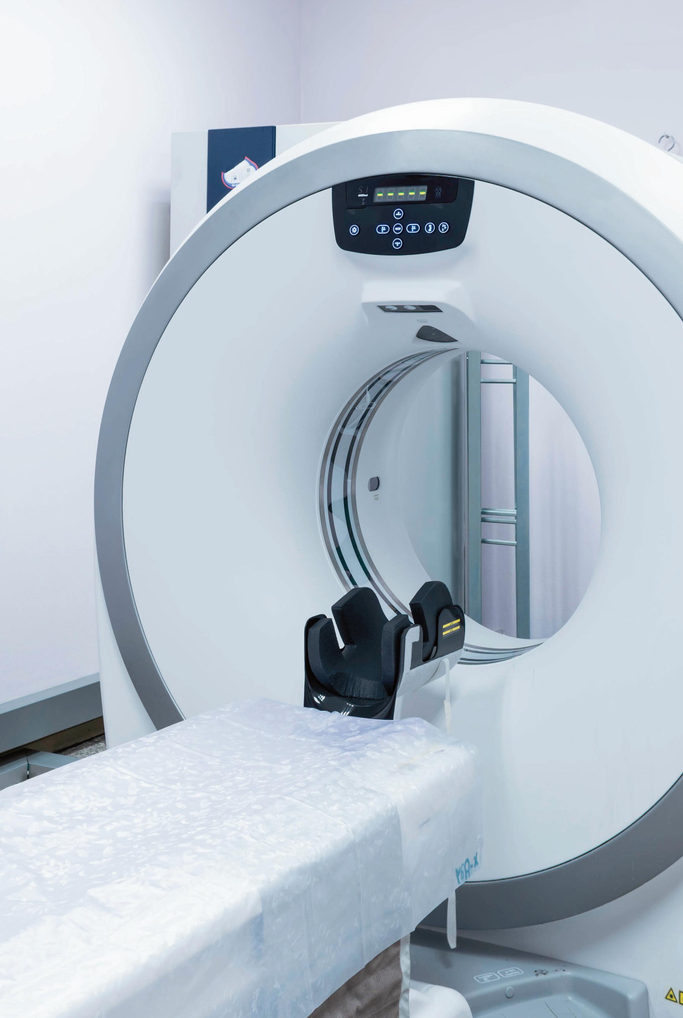


Plastic and metal gears also experience different types of contact under load. Metal gears have primarily line contact, with one tooth in mesh at a time. But plastic gear teeth have an involute surface that deforms under load, distributing the contact pressure across a larger surface and allowing contact between adjacent teeth. This provides load sharing among teeth and helps to improve the life of plastic gears in some applications — especially those with high impact loads and relatively low continuous loads. The lighter weight of plastic gears means they have lower inertia than their metal counterparts, which is essential for aerospace and some military applications. In addition, most plastic gears can run without lubrication ... or can be embedded with lubricating materials such as graphite, silicone, or PTFE. However, some operating conditions benefit
Because the shafts of hypoid gears don’t intersect, bearings can be used on both sides of the gear to provide extra rigidity.
The difference in spiral angles between the pinion and the crown (larger gear) causes some sliding along the teeth, but the sliding is uniform, both in the direction of the tooth profile and longitudinally. This gives hypoid gearboxes very smooth-running properties and quiet operation. But it also requires special extreme pressure (EP) gear oil to maintain effective lubrication due to the pressure between the teeth.
From Concept
Bison & Engineering is an industry leader in designing and manufacturing
To Creation
Motion Systems Handbook 44 DESIGN WORLD — MOTION
Gear
custom gearmotors for the fractional horsepower market. Our engineering team will work with you to find the perfect solution for your power transmission needs. Challenge us today with your custom www.bisongear.comproject
Hypoid gearboxes are generally used where speeds exceed 1,000 rpm ... although above 8,000 rpm ground gears are recommended. However, hypoid gearing is also useful for lower speed applications that require extreme smoothness of motion or quiet operation. In multistage gearboxes, hypoid gears are often used for the output stage, where lower speeds and high torques are required.
When determining whether a plastic gear will be suitable for a particular application, the most critical factor is environment. Some though not all plastics maintain less dimensional stability than metals ... and in a few cases, their strength and stiffness characteristics are dependent on temperature and exposure to water or chemicals. When properly specified, plastic gears will exhibit no swelling or shrinking.
The most common application for hypoid gearboxes is in the automotive industry, where they are used in rear axles — especially for large trucks. With a left-hand spiral angle on the pinion and a right-hand spiral angle on the crown, these applications have what is known as a below-center offset ... which allows the driveshaft to be located lower in the vehicle. This lowers the vehicle’s center of gravity and in some cases reduces interference with the interior vehicle space.
Industrial-grade plastic gearing
Plastic gears are primarily recognized for their quiet operation and resistance to rust — attributes that are important the food processing, medical equipment, and chemical processing industries, as well as in consumer applications. But plastic gears offer many other benefits, and advances in materials and manufacturing processes are helping to close the remaining performance gap between plastics and metals in gearing applications.


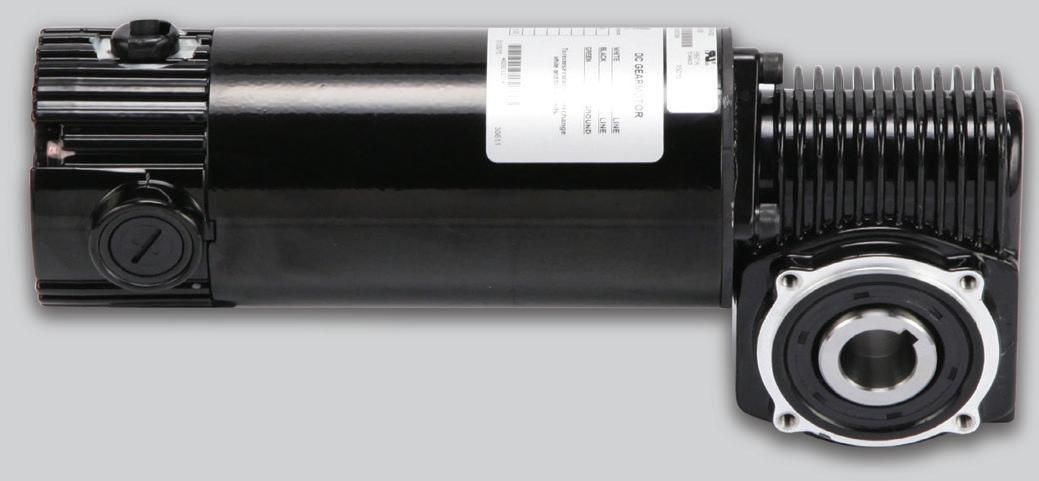


46 DESIGN WORLD — MOTION 8 • 2022 motioncontroltips.com | designworldonline.com
The variety of plastics that are suitable for gear applications is extensive, but common choices include nylon, acetal, polycarbonate, polyphenylene sulfide, and polyurethane. The addition of glass fiber can improve the stiffness and heat conductivity of some materials, although it reduces the material’s fatigue endurance. Plastic gears can be processed by injection molding for lower cost than machined plastic gears. However, machined plastic gears typically offer better tooth strength and can be produced to meet higher AGMA quality levels than can be achieved with injection-molded versions.
IN.)LB/SQ(KILOSTRENGTHENSILET MOISTURE (%) 9876543210 101286420 NYLON 6 NYLON 6.6 CAST NYLON 12 WATER ABSORPTION (%) (%)INCREASELENGTH 0.51.52.53.5123 1 234 5 67 8 90 NYLONNYLON6 6.6 CAST NYLON 12 NYLON 11 POLYAMID GEARS IN MOISTURE MOISTURE ABSORPTION AFFECTS TENSILE STRENGTH SOME PLASTICS USED IN THE CONSTRUCTION OF GEARS EXCEL IN WET SETTINGS. FOR EXAMPLE, CAST NYLON (POLYAMIDE-12) GEARS THAT ARE SUBMERGED DURING OPERATION NEVER SWELL BEYOND A TENTH OF A PERCENT. THAT’S FAR LESS MOISTURE ABSORPTION THAN OTHER NYLONS USED IN CONSTRUCTING PLASTIC GEARS — FOR MAINTENANCE OF DIMENSIONS AS WELL AS RATED TENSILE STRENGTH.
A metal hub — either molded into the gear or assembled after manufacturing — can help in heat dissipation. It can also increase the rigidity of the gear and provide a secure surface for fastening the gear to the shaft. KALINOVSKY
Motion Systems Handbook WORM-GEAR|COURTESY OF DMITRY
If the lubricant isn’t compatible with the plastic material, stress cracking or even failure of the plastic can result.
from (or even require) lubrication. Choosing a lubricant for plastic gears should take into consideration the environmental, load, and speed conditions in which the gears will operate.
Due to sliding contact, plastic worm gears can in some cases experience heating which in turn decreases strength and accelerates wear. Speed capability is limited for such plastic worm gears, and lubrication is typically recommended.
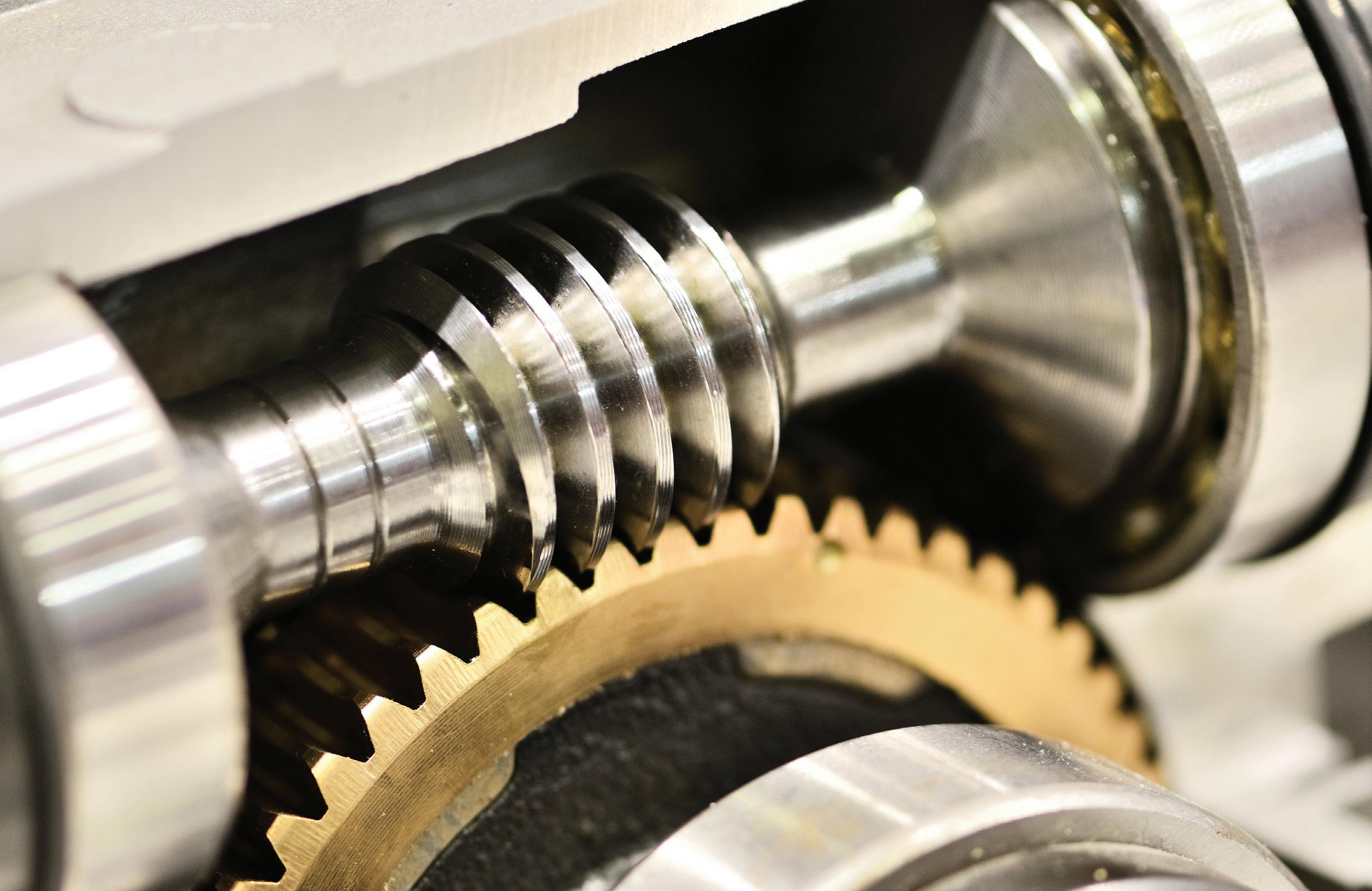
The MOVI-C modular automation system from SEW-EURODRIVE is a onesoftware, one-hardware automation platform that combines fully integrated drive components, control electronics and automation software – all from one source. The key to the MOVI-C platform is that each of those components is designed to work together perfectly. More control. Less programming. MOVI-C works with decentralized control architectures as well as centralized approaches, from the controller and inverter all the way to the gearbox. MOVI-C components can be fully integrated into all network standards and fieldbus topologies such as EthernetIP, PROFINET, PROFIBus, Modbus, EtherCAT and OPC UA. This is automation made simple.
seweurodrive.com/movi-c
Goodbye complex automation. Hello MOVI-C® .


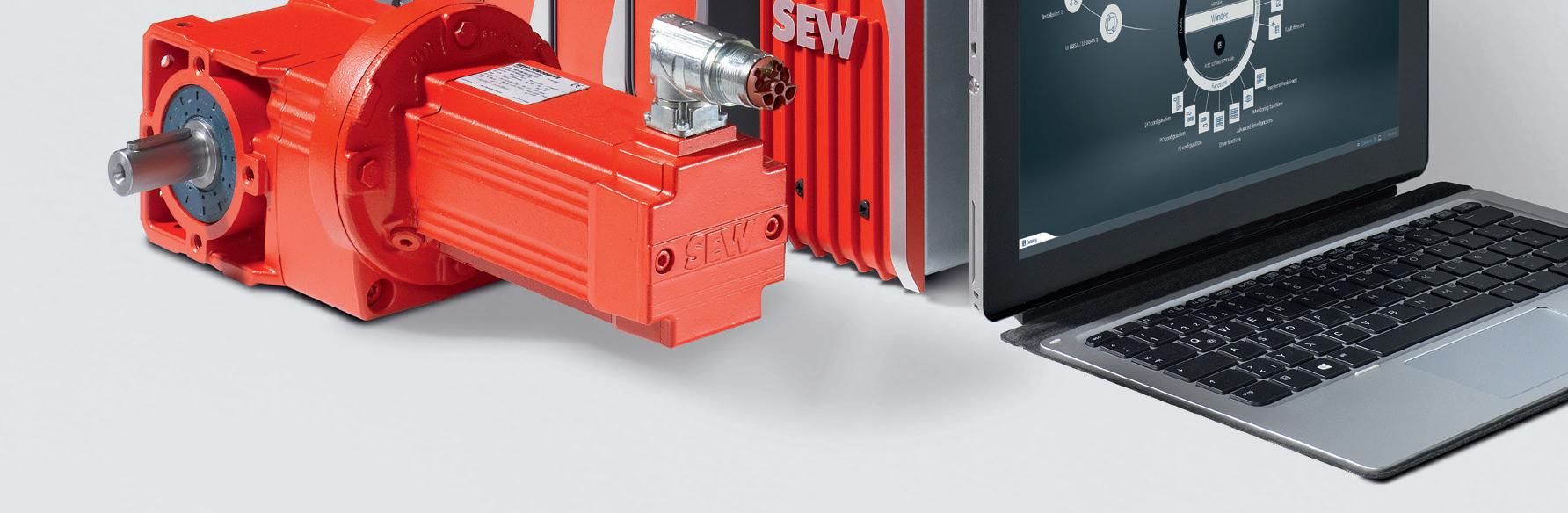

As covered in earlier Motion Handbook installments, ball splines are a type of rolling-bearing linear guide. They’re much like linear bushing (round shaft and bushing) assemblies but with a critical distinction in their operation. The ball-spline shaft is much like a linear-guide shaft except that the spline shaft has grooves along its length. The spline nut (analogous to the bearing, or bushing, of a traditional rolling bearing guide) contains circuits of recirculating balls. But instead of the spline nut riding freely on the shaft with the ability to rotate during linear travel, the load-carrying balls ride in the shaft grooves that constrain the spline nut and totally prevent rotation.
Consider how transferring a workpiece from one station or conveyor to another might involve:
In this case, a rotary ball spline can be driven by a pneumatic cylinder (for the linear motion) in conjunction with a belt-and-pulley system for the rotary motion. Ball-spline designs fall into two categories — those for torque transfer and those for combined linear and rotary motion. Ball splines for torque transfer abound in machinery for product assembly, welding and plating, wire winding, paper processing, and material handling. In contrast, ball splines for combined linear and rotary motion abound in pick-andplace robotics, water jets, automatic tool changers, laboratory equipment needing quick transfers of pipettes and other test samples, and packaging equipment. Ball splines for torque transfer: A ball spline is essentially a linear bushing and shaft pairing … except with both the axial shaft and the nut ID sporting axial grooves … hence the term spline. Load-carrying balls recirculate within the nut just as they do in a linear bushing. However, the grooves in the shaft prevent rotation and facilitate the transmission of torque. This allows ball splines to withstand overhung loads and moment loads, unlike linear bushings, which can only support radial loads. The ball-spline assembly’s part housing the recirculating balls is called a nut — and not usually called a bushing. Even this terminology is somewhat imperfect though … as a ballspline nut’s functionality is indeed different from that of a ballscrew’s recirculating-ball nut. Because the design of a ball spline affords much greater contact area between the balls and the grooves than that of standard bushings, ball splines have significantly higher load capacities. Ball splines typically have two, three, or four grooves … although some designs have up to six grooves. Like the raceways of profiled rail bearings, the grooves in a ball spline can be designed with either: Circular arch geometry for two-point contact on each ball Gothic-archor geometry for four-point contact on each Essentially,ball. Gothic arch geometry provides higher rigidity but also contributes to higher friction. In contrast, circular arch geometry has lower friction and smoother running characteristics. Torque capacity is determined by the number of contact points, so a ball spline with four Gothic arch grooves will have 16 contact points and transmit more torque than an otherwise identical component with two Gothic arch grooves and just eight contact points. Sizing and selection of ball splines combines technical considerations from both linear recirculating bearings and ballscrews. Life is calculated via the standard bearing life equation, using both radial loads and torque
Motion Systems Handbook
Another version of the ball spline is the rotary ball spline, which incorporates a rotating element — such as an angular contact ball bearing, crossed rollers, or gear teeth — on the outer diameter of the nut. This adds the capability of rotary motion to the linear motion provided by the ball spline — somewhat like a cross between a recirculating linear guide and a ballscrew. Because the recirculating balls of the spline nut ride in grooves, the contact area is greater than for ball bushings, giving ball splines much higher load capacities than ball bushing assemblies of the same size. But even though higher load capacity is a benefit, the primary reason many designers and engineers use ball splines is their ability to prevent rotation or (in the case of rotary ball splines) to provide both linear and rotary motion in one device. Traditional linear bushings are almost exclusively used in dual-shaft configurations to prevent the bearings from rotating as they ride on the shafts. But since ball splines are inherently anti-rotation, they can be used in single-shaft configurations. And replacing two shafts with one also means a smaller footprint, less weight, and easier alignment and assembly. Linear and rotary motion in one: Rotary ball splines also provide excellent solutions for Z-theta axes on SCARA robots.
• Picking the part from the first station — with vertical motion • Rotating to the position of the second conveyor — with rotary motion
• Placing the part on the second conveyor — with vertical motion
SPLINES TO LINEAR-GUIDESERVEFUNCTIONS 48 DESIGN WORLD — MOTION 8 • 2022 motioncontroltips.com | designworldonline.com | COURTESY OF VIOREL DUDAU
The spline shaft provides the Z (vertical) movement. The rotary bearing on the spline nut then provides the ϴ rotational movement. These properties also make rotary ball splines suitable for automatic tool changers in CNC machine Pick-and-placetools.or assembly applications also make copious use of rotary ball splines.

Rotary ball splines incorporate a rotating element — angular contact ball bearings, crossed rollers, or gears — on the outer diameter of the nut. This provides rotary motion in addition to the linear motion of the ball spline itself. Both standard and rotary ball splines are offered with a hollow spline shaft, which helps with integration into systems such as SCARA robots … allowing electrical or pneumatic lines to route through the spline shaft. In fact, one of the most common applications for rotary ball splines is the Z-theta axis of SCARA robots. Linear ball-spline rigidity — a characteristic of paramount importance in designs that need a ball spline to execute reciprocating circular or straight strokes or withstand vibration and impacts — is largely dependent on ball-bearing preload. This preload is the removal of all mechanical clearance (radial play) in the ball-spline nut’s rotational direction … and in fact, this value is often called negative clearance. So how exactly is preload (negative clearance) introduced into a ball-spline assembly? Well in many cases, the manufacturer sets this value at the factory. But where that’s the case (or the OEM or end user sets the preload) essentially this is set by introducing a slight interference fit between the shaft’s grooves and the nut tracks (and their balls) that ride these grooves. In some cases, this preloading is set by the inclusion of balls that are slightly larger than those used in otherwise
A ROTARY BALL SPLINE CAN INCORPORATE ANGULAR CONTACT BEARINGS (AS SHOWN) OR CROSSED ROLLERS OR EVEN GEARS TO PRODUCE ROTARY MOTION.
motioncontroltips.com | designworldonline.com loads. Like profiled rail guides, ball splines can be preloaded to increase rigidity and provide better support for moment loads. Ball splines are fixed with rotary bearings much like ballscrews, and the end fixity (such as fixed-fixed or fixed-floating and so on) influences critical speed — as do the shaft root diameter and unsupported length. Accuracy grades are also assigned to ball splines in a way that’s similar to those assigned to ballscrews — based on:
• Perpendicularity of the nut flang (where However,applicable).ball-spline accuracy classes aren’t based on industry standards such as DIN or JIS. That means one manufacturer’s “top-precision” accuracy class may be similar to another manufacturer’s middle-of-the-road accuracy class.
Rotary ball splines for combined linear and rotary motion: While recirculating linear bearings provide linear motion and ballscrews provide rotary motion, rotary ball splines fill the gap between the two — generating both linear and rotary motion.
Linear guides & rails • slides & ways 49DESIGN WORLD — MOTION8 • 2022
• Radial runout and perpendicularity of the shaft ends • Radial runout of the nut body


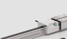
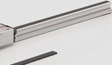
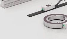


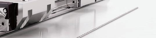


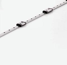


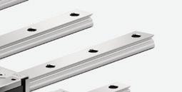
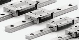


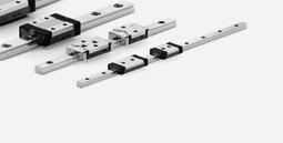


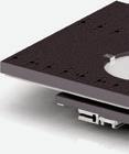
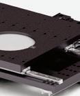
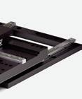
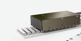


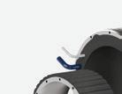
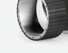


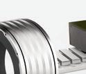
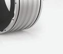


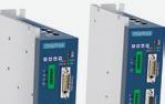


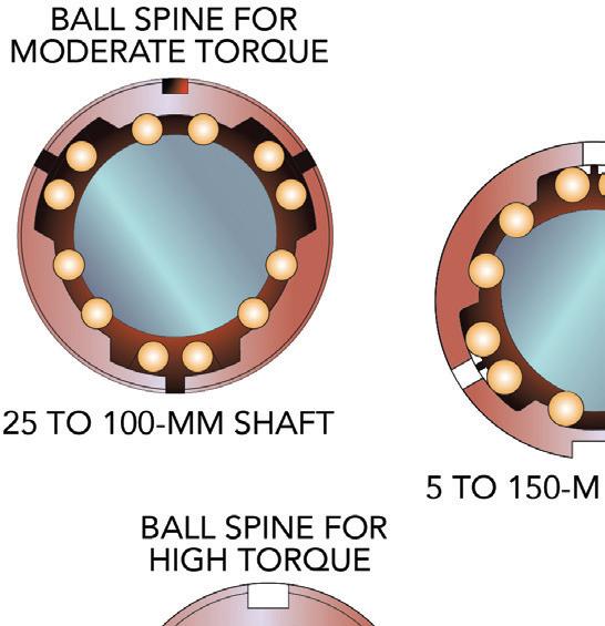

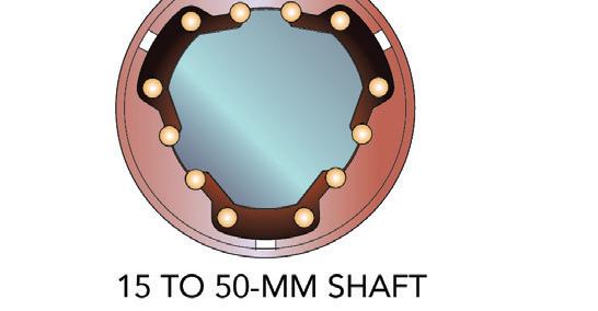
LINEAR
versatility and
adapt to various workpieces, offering
Most ball-spline manufacturers publish guidelines for typical ball-spline applications and their recommended preloading or clearance values. Most ball-spline manufacturers also express preload as a negative value in micrometers (μm) ranging from a positive value of say 1 to 7 μm — which in fact indicates a small amount of intentionally included clearance or backlash — to -1 to -20 μm for common levels of preloading or even -25 to -40 μm for rather heavily preloaded assemblies.
TWIN RAILS
…
fingers in each position. WIDE RANGE OF USE Suitable for both industrial and collaborative robots. Visit phdinc.com/flexion to see FLEXION in action. Empowering Automation A gripper inspired by the motion of a human finger 50 DESIGN WORLD — MOTION Motion Systems Handbook UNLIKE
One complicating factor in the specification of ball-spline rotational clearance is that of inertia — especially in systems subject to various load and speeds. Axes with high moments of inertia about the ball-spline assembly will exhibit more backlash and degradation of positioning accuracy. Even so, there are reasons to avoid preload in the rotational direction for some ball-spline applications: Axes involving modest loads and force requirements and axes that always turn in a single direction (as on instrumentation that uses spinning or scanning functions) are some examples. Other examples of applications needing no preload include web-winding equipment and certain axes on automated welding robots.
A BALL
CONFIGURABLE SYSTEM Modules can be assembled in radial
Another approach to addressing ball-spline backlash is to employ twin nuts on a single shaft. Ball splines with moderate preload (even to -40 μm) make sense where a design requires the maximum possible rigidity for an axis — even when subject to vibration and impact loading. Such applications include axes relying on single ball splines, lathes, welding machines, and off-highway applications. conform and an unmatched level of application potential. or parallel hub to five THE STRAIGHTFORWARD DESIGN OF A SYSTEM BASED ON SPLINE, OTHER TYPES OFTEN NECESSITATE OR MECHANISMS WHICH IN TURN
ADAPTIVE DESIGN Finger modules flex multiple joints to
comparable ball-spline nuts. Elsewhere, the preload is introduced by the slightest of offsets between the nut’s rows of balls and the spline’s groove crests.
Light preload (of -10 to -20 μm or so) makes sense on motion axes for positioning precision loads — as in semiconductor applications, die setting (in machine-tool presses), or pick-andplace arms tasked with populating a conveyor with delicate workpieces. Lightly preloaded ball splines are also suitable for axes involving oscillating loads and overhung loads (moments) and various guide-shaft applications.
arrays with one
INCREASES OVERALL DESIGN COMPLEXITY AND SIZE.
So for example, a spline shaft having three crests will receive flanking by twin rows within a six-row nut for secure bidirectional engagement … and symmetrical application of preload. This and an appropriate shaft-to-nut contact angle impart high-torque moment rigidity sans angular clearance … with higher contact angles complementing preload with the most rigidity.
LINEAR-BEARING


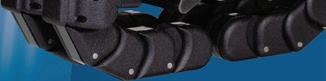


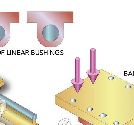


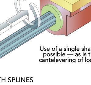

whenLinearPrecisionMotionyouneed it NOW! Order Today! 800.245.5013 • deltron.com ISO 9001:2015/AS9100D CERTIFIED MADE IN USA Linear Motion Specialists 800-245-5013deltron.com Solid Models Available for all Del-Tron Model Numbers MarketsVarietyAServeDesignedComponentsLinearEngineeredCustomAndStandardMotiontoWideof
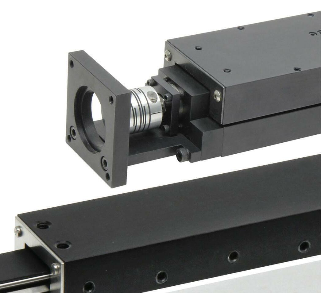
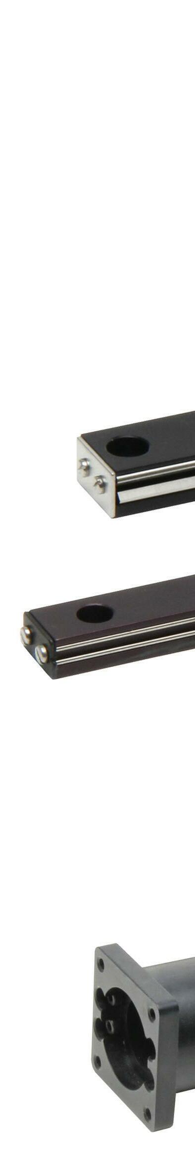
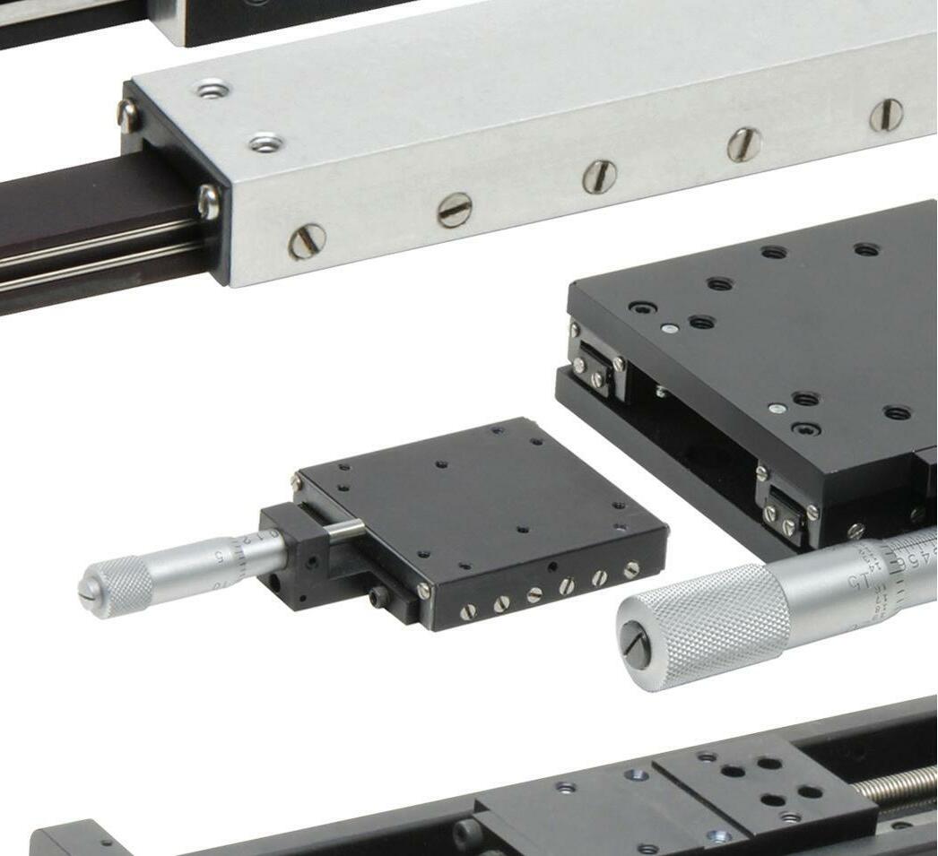
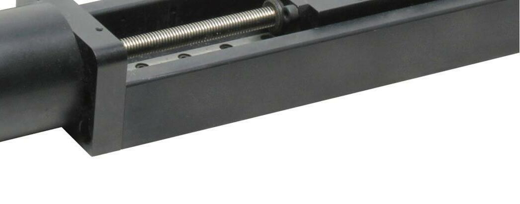


Systems Handbook
SCREW ACTUATORS
The permissible operating speed of a ball screw assembly depends on two parameters — critical speed and characteristic speed. Characteristic speed is determined by factors related to the ball nut, including the ball return system and the mass of the balls. However, improvements in ball nut manufacturing and ball recirculation methods have provided most ball screw assemblies with high characteristic speeds, so the limiting factor is typically the criticalForspeed.arotating shaft, such as a ball screw assembly, critical speed is defined as the angular velocity that excites the natural frequency, or first resonant frequency, of the assembly. If the shaft is operated at its natural frequency, it can begin to resonate, causing severe damage — or even destruction — to the assembly.Intheory, a shaft is perfectly balanced — that is, its mass is perfectly distributed about its volume — so that when it rotates, there is no bending of the shaft and the center of mass lies along the axis of rotation. But in the real world, even the most precisely manufactured and machined shafts are not perfectly balanced, so the center of mass is slightly offset from the axis of rotation. In addition, because the screw shaft is supported only at
Focus on ball screw whip Ball screws are often the drive mechanism of choice in applications that require high thrust forces with excellent positioning accuracy and repeatability. But one of the drawbacks of ball screw technology is that speed is inversely related to length — the longer the ball screw shaft, the more likely it is to whip, like a jump rope, as it turns. This behavior limits the maximum travel distance that can be achieved when high speeds are necessary, and vice-versa.
52 DESIGN WORLD — MOTION 8 • 2022 motioncontroltips.com | designworldonline.com AS A BALL-SCREW SHAFT ROTATES, IT BEGINS TO WHIP – MUCH LIKE A JUMP ROPE. THIS BEHAVIOR LIMITS THE SCREW’S CRITICAL SPEED.
Motion
– HOW TO KEEP BALL SCREWS IN LINE
LEAD DEVIATION PER 300 MM DEFINES THE MAXIMUM RANGE OF TRAVEL DEVIATION (PEAK-TO-VALLEY) OVER ANY 300 MM SECTION OF THE USEFUL SCREW LENGTH. cost, precision ground ball screws, while lower lead accuracy and some axial play is associated with lower-cost, rolled ball screws. Fabricated by rolling or other means, ball screw shafts yield a less precise, but mechanically efficient and less expensive ball screw. Ball recirculation inside the ball nut can impact precision and repeatability. Thus, ball nuts are available with a range of preload options to reduce or remove the axial play as they rotate around the screw. Minimal axial play allows better accuracy, for example, because no motion is lost from the clearance in the balls as they reengage.
Screw drives used in power transmission and motion applications are one of two types: screws that rely on sliding contact such as lead screws, and those that use re-circulating balls or rollers, for ball or roller screws respectively. The sliding contact design is used primarily in applications that require corrosion resistance and selflocking operation, while ball or roller screws are mainly used where high rigidity, high duty cycles, and position accuracy is key. Ball screws have a few basic components including a nut, a screw with helical grooves, and the balls that roll between the nut, the screw, and the grooves when either the screw or nut rotates. The balls are typically made from either steel, ceramic, or some hard plastic material. The balls are routed into a ball return system of the nut and travel in a continuous path to the ball nut’s opposite end. Seals are typically used on either side of the nut to prevent debris from compromising screw operation. Ball screws are typically classified according to a few key parameters including lead accuracy, axial play and preload, and life/ load Leadrelationship.accuracy refers to the degree to which the shaft’s rotational movements are translated into linear movement. With lead accuracy and axial play determined by the manufacturing method of the ball-screw shaft and the assembly of the nut, high lead accuracy and zero axial play is generally associated with relatively higher-
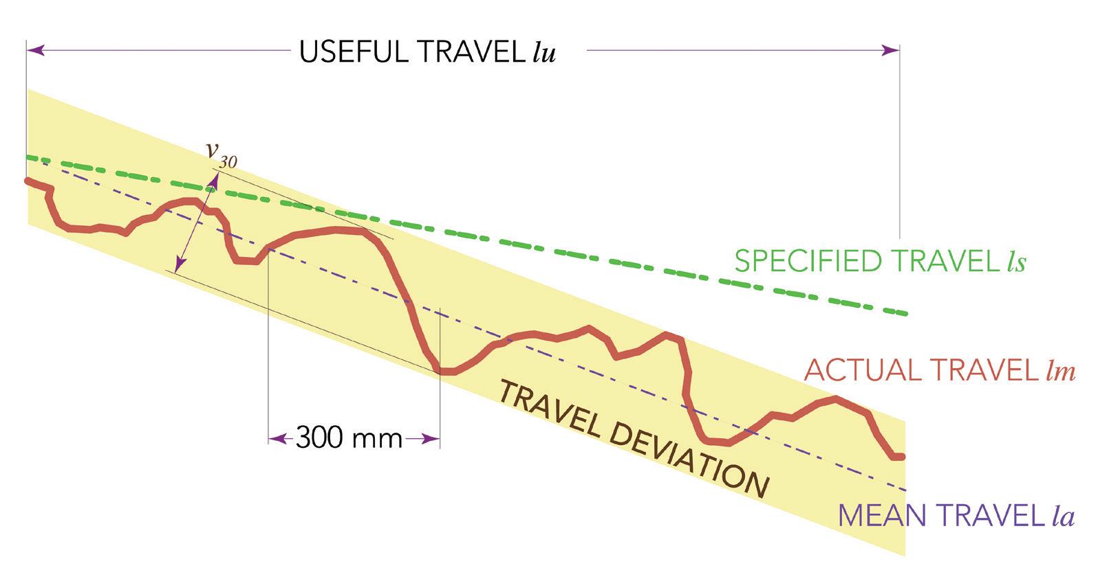
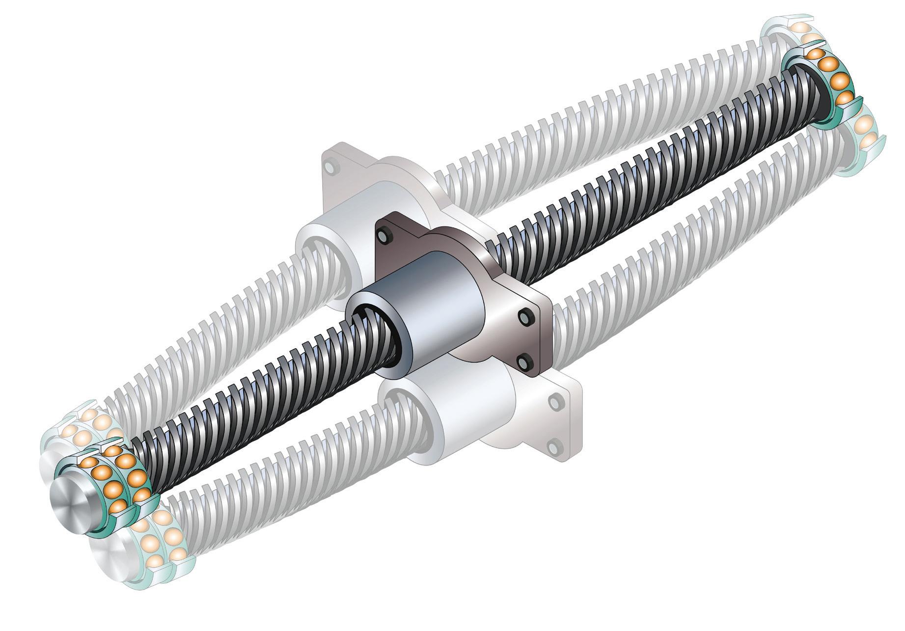
A power transmission screw translates rotary motion to linear motion through a helix formed around the screw shaft. When “unwrapped” from the screw shaft, the ideal helix thread will form a straight line that serves as the hypotenuse of a right triangle, with the other two sides being the circumference of the screw and the pitch, or lead, of the screw. However, variations in the thread helix will cause it to produce a curved line when unwrapped. This curvature of the helix represents erratic motion of the screw with each individual rotation.
If this vibration — or ball screw whip — approaches or reaches the natural frequency of the screw shaft, resonance can ensue and lead to increased noise, damage, and, in extreme cases, yielding of the shaft.
Ball scre follow industry standards such as DIN ISO 3408, JIS B1192-1997, or ANSI-B5.48 for accuracy classifications. Two of the most common ball-screw lead accuracy specifications are lead deviation per 300 mm and lead deviation per revolution.
In DIN ISO and JIS standards, this travel deviation within one revolution of the screw is defined by the specification ν2π, whereas the ASTM standard refers to this specification as wobble error.
WWW.NSKAUTOMATION.COM MORE LINEARDH/DSOPERATINGDOUBLETHANTHELIFE.SERIESGUIDES. Maximize machine uptime with long-life Tough Steel technology. NSK DH/DS series linear guides deliver outstanding positioning accuracy with precedent-setting capacity and operating life. NSK’s proprietary Tough Steel material technology augments optimized ball circulation and rolling contact to deliver 26% higher dynamic load ratings, and double the fatigue life of our conventional product series. Even in the toughest operating environments. Enabling Automation in Motion & Control. 53DESIGN WORLD — MOTION8 • 2022motioncontroltips.com | designworldonline.com Linear scre A LOOK AT BALL SCREW ACCURACY STANDARDS
Lead deviation per revolution
The DIN ISO and JIS standards classify ball screws as one of two types: positioning or transport. Positioning screws are denoted with the letter “P” by DIN ISO, and with the letter “C” by JIS. Transport screws are denoted with the letter “T” by DIN ISO, and with the letters “Ct” by JIS.
The ν300 lead accuracy specification applies to both positioning and transport screws, although there are slight differences between the ν300 values for DIN ISO versus JIS versions. However, lead deviation per revolution, ν2π, is only defined for positioning screws. its ends, it bends somewhat under its own weight, moving the center of mass even farther from the axis of rotation. As the ball screw shaft rotates, the discrepancy between the center of mass and the axis of rotation produces centrifugal forces, which cause the shaft to deflect, or whip, like a jump rope.
Lead deviation per 300 mm Lead deviation per 300 mm defines the maximum range of travel deviation (peak-to-valley) over any 300 mm section of the useful screw length. In the DIN ISO and JIS standards for ball screws, this specification is denoted as ν300, while the ANSI ball screw standard refers to it as maximum rate error.
Each type of ball screw — positioning or transport — is further broken down into numerical accuracy grades, with lower numbers indicating higher (better) accuracy. For example, P3 and T5 are both DIN ISO accuracy classes (with P3 being higher, or better, accuracy than T5), while C1 and Ct7 are JIS accuracy classes (with C1 being higher, or better, accuracy than Ct7).
P itioning versus transp t ball scre


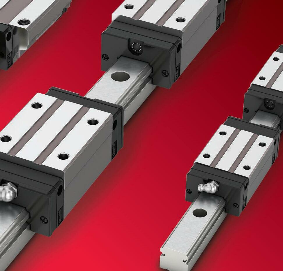


FRAMELESS SERVO MOTORS, SUCH AS THE TBM2G SERIES FROM KOLLMORGEN, ARE MOST SUITABLE FOR ROBOTIC APPLICATIONS IN MEDICINE AND AEROSPACE WHERE THEY OFFER HIGH-PERFORMANCE TORQUE IN A COMPACT PACKAGE. THESE MOTORS ENABLE ROBOTS WITH LOWER JOINT WEIGHT, HIGHER LOAD-CARRYING CAPACITY, AND IMPROVED ENERGY EFFICIENCY FOR FASTER AND SMOOTHER MOVEMENTS.
Motion Systems Handbook
Recall that brushless dc motors use permanent magnets on the rotor and coils in the stator to produce rotation (and torque). This configuration is similar to a synchronous ac motor, but a key difference between BLDC motors and synchronous ac motors is in how the stator coils are wound. In a synchronous ac motor, the coils are wound sinusoidally and commutation is a continuous, sinusoidal waveform. This gives synchronous ac motors smooth performance. BLDC motors, on the other hand, have trapezoidally wound stator coils and commutation that takes place in six steps (every 60 degrees), which can lead to torque ripple.
Brushless dc motors are typically constructed with a stator made from slotted steel laminations and copper windings inserted into the slots. Slotted designs can be constructed with the rotor at the center of the motor and the stator surrounding the rotor (sometimes referred to as an “inrunner,” or internal rotor, design). This reduces the motor’s inertia and allows for dynamic performance. Alternatively, slotted BLDC motors can be constructed with the slotted stator at the center of the motor and the rotor magnets surrounding the stator (sometimes referred to as an “outrunner,” or external rotor, design). This allows the motor to produce high torque and to be constructed with a short overall length (referred to as a “flat” design), but at the expense of reduced dynamics due to higher rotor inertia. Whether constructed with an internal or external rotor, slotted BLDC motors suffer from cogging torque due to the permanent
MOTOR OPTIONS FOR PRECISE POSITIONING 54 DESIGN WORLD — MOTION 8 • 2022 motioncontroltips.com | designworldonline.com
Note that brushed dc motors are capable of operating in a servo system, but the wear and maintenance they require — due to the mechanical brushes and commutator — make them less desirable for most servo applications.
BLDC mot construction variations
F motion applications that need precise positioning, there are a few different types of motors that are suitable in such cases. For instance, stepper motors work for precise positioning and control with torque. Intermittent moves are what steppers output best. Stepper motors are also suitable on axes that must hold loads still for extended lengths of time, as the motors can remain in one position indefinitely. With proper design and damping, the motors can also output motion with minimal velocity ripple. Additionally, stepper motors have high repeatability and are reliable. From a cost perspective, they are often far cheaper than servomotors and can often be used in applications where servomotors are used with significant savings. However, stepper motors shouldn’t be used in applications with continuous operation. When applications need motors to operate nonstop, steppers exhibit dwindling efficiency and torque. Servo motors are the other common choice. Servo motors are used in applications where precise control of position, speed, or torque is required. But many different types of motors can be considered servo motors — the defining feature of a servo motor is that it incorporates or reads feedback in a closedloop system. In fact, although many servo applications use synchronous ac motors, dc motors can also be used in servo systems. Synchronous ac motors are typically brushless, with the exception being universal motors, which are mechanically commutated with brushes and can run on either an ac or dc power supply. Likewise, the dc motors used in servo systems are most commonly brushless types, typically referred to as BLDC motors.
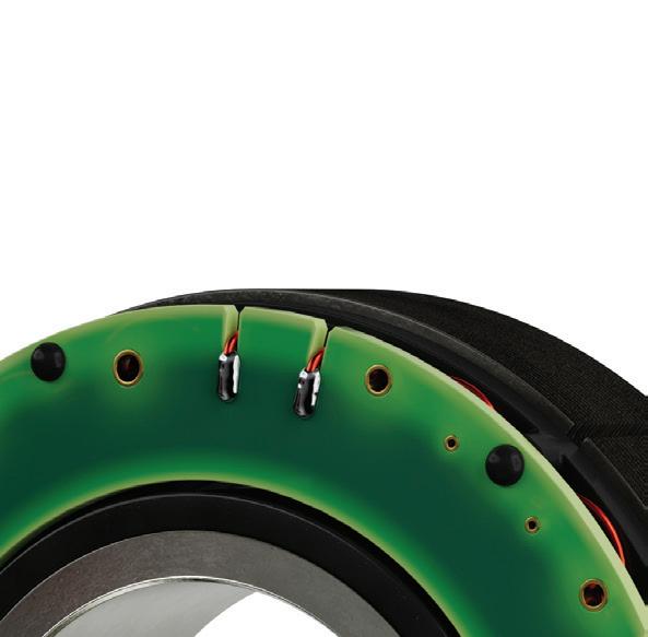
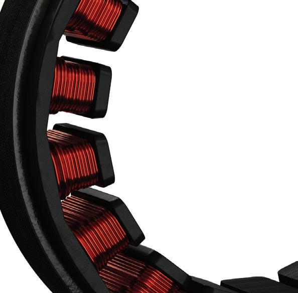
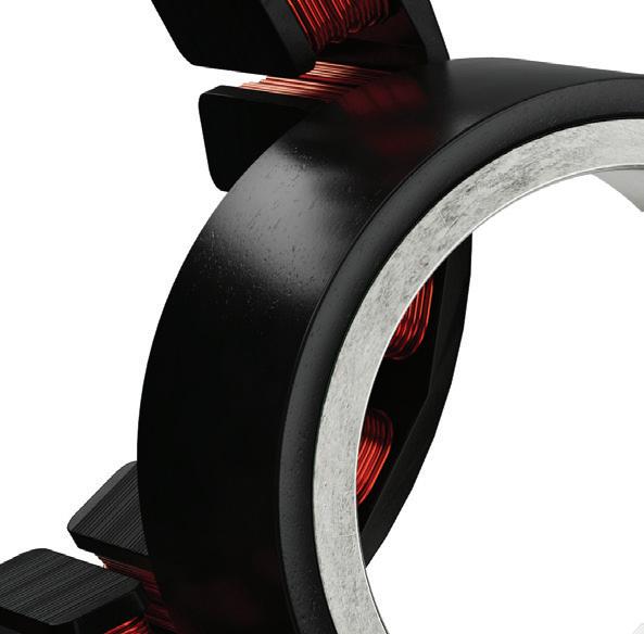
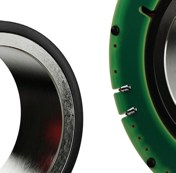
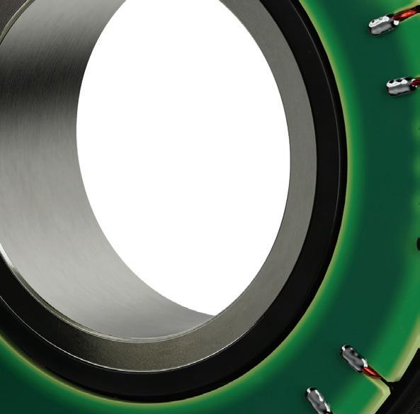
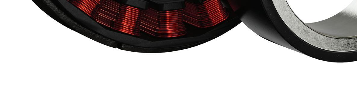
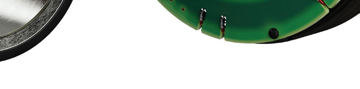


NEWER BRUSHLESS SLOTTED FLAT MOTORS, SUCH AS THE 32ECF FROM PORTESCAP, FEATURE AN 8-POLE DESIGN AND HIGH-POWER DENSITY IN A FLAT ARCHITECTURE. THE MOTOR DIAMETER IS 32 MM AND IT USES AN OUTER ROTOR CONFIGURATION WITH AN AIR GAP BETWEEN THE COIL AND MAGNETIC STRUCTURE THAT IS MANAGED RADIALLY. SUCH SMALL MOTORS ARE SUITABLE FOR APPLICATIONS WHERE SPACE IS LIMITED SUCH AS IN LAB AUTOMATION AND ROBOTICS.
MOTION DESIGN GUIDES A collection of key motion control technology topics available for download CHECK OUT Design World ’s online Motion Design Guide Digital Library. The editors of Design World produce relevant content broken out by key technologies. Motion Design Guide categories include (but are not limited to): • Linear Actuators • Gearmotors • Gearboxes • Couplings • DC Motors • Linear Guides + more BOOKMARK: designworldonline.com/design-guide-library Additional Design Guides are added on an ongoing basis. 56 DESIGN WORLD — MOTION 8 • 2022 motioncontroltips.com | designworldonline.com
Motion Systems Handbook
A newer permutation of the BLDC motor is the slotless design. This design does away with the slotted steel laminations and instead uses a stator constructed of steel rings stacked together, with the windings encapsulated in an epoxy resin. The winding is placed in the air gap between the stator lamination and the rotor, which resides in the center of the motor. The slotless design eliminates cogging torque, reduces audible noise, and reduces inductance, so acceleration and dynamic response are improved over slotted designs. BLDC motors are often used in servo applications that require high efficiency, high reliability, and good torque density (torque production for a given size), but without the magnitude of torque production that can be provided by larger, synchronous ac motors. Common applications for BLDC servo motors include robot joints, medical devices, and packaging equipment. BLDC motors are also suitable for battery-powered equipment and for applications that require direct integration of the motor into the mechanical design, thanks to their numerous design options and the myriad ways they can be customized.
magnets in the rotor attempting to line up with the slots of the stator. The primary effect of cogging torque is that it causes motor rotation to be jerky, especially at low motor speeds.
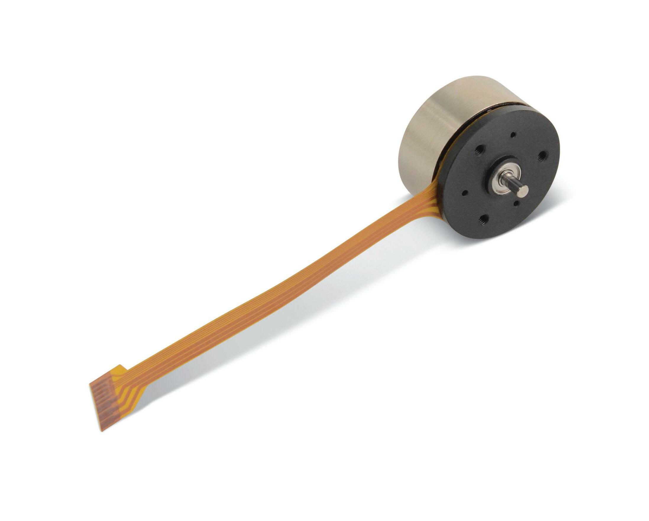


Meeting Customer Needs with Diverse Product Categories and Customized Products Linear Piezo Motor DC Brushless Servo Motor Canon Precision proprietary technology and internal production systems provide our partners with micro-motor design flexibility, quality control and rapid delivery. Canon Precision motors can also be equipped with optional gear units and encoders and can be optimized to meet your size, speed, gear ratio and reliability requirements. CANON U.S.A., INC. Motion Control Products 3300 North 1st Street • San Jose, CA 95134 TEL: 1-408-468-2320 • Email: motors@cusa.canon.com www.usa.canon.com/ Canon is registered trademark of Canon Inc. in the United States, and may also be registered trademarks or trademarks in other countries. All other referenced product names and marks are trademarks of their respective owners. Specifications and availability subject to change. Not responsible for typographical errors. ©2021 Canon U.S.A., Inc. All rights reserved.
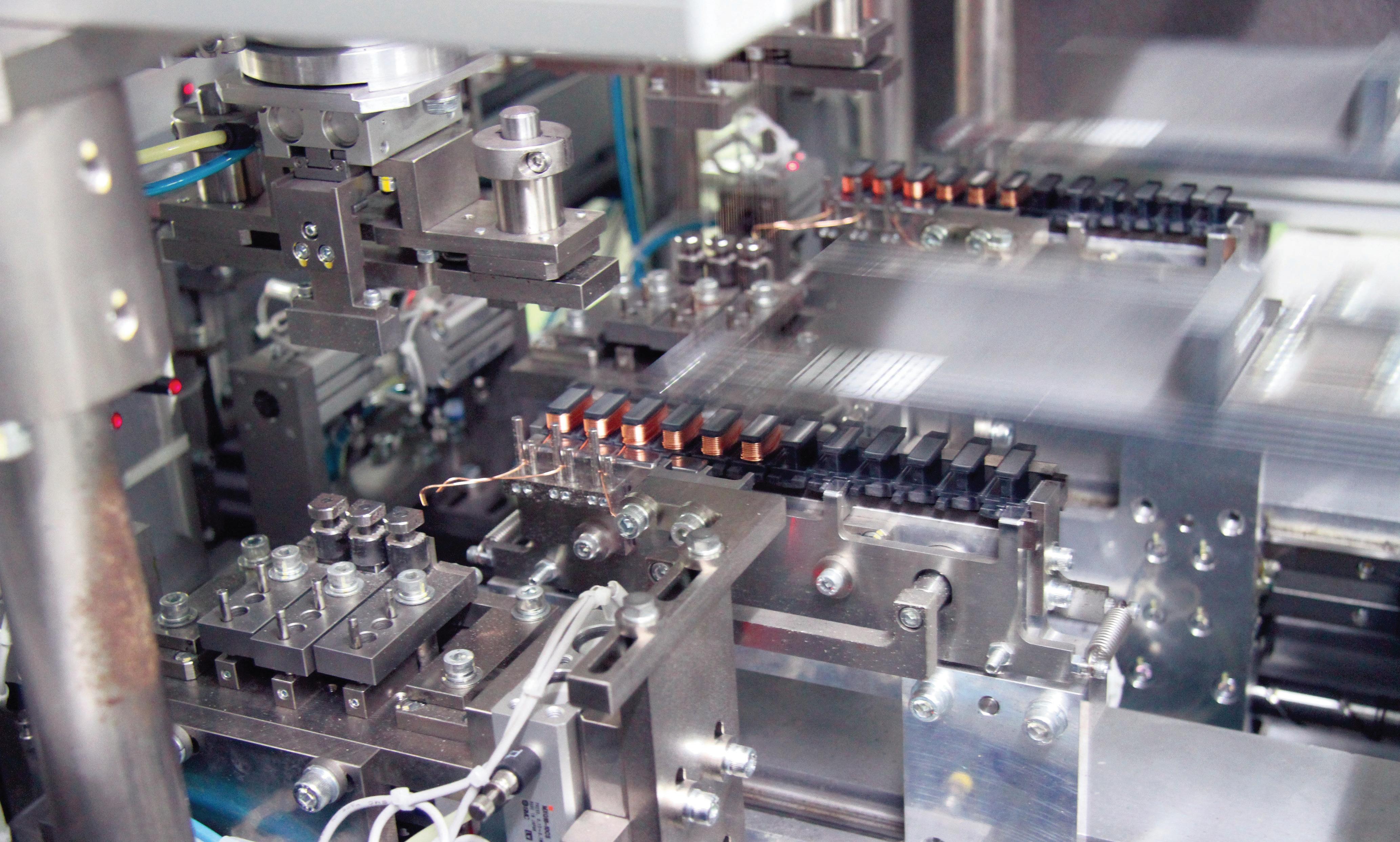

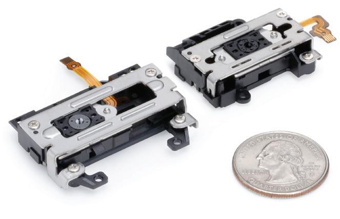
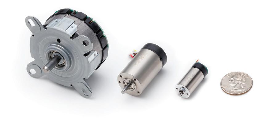


A look at design Shock absorbers are essentially small-bore hydraulic cylinders equipped (or drilled) with orifices in the piston. Those orifices’ combined cross-sectional area dictates the piston’s flow rate potential. The “compound orifice” of the drillings equates to an overall orifice size that adheres to any chart displaying pressure versus flow curves. The smaller the orifice size, the less flow across the shock absorber piston and the higher spring brakingLargereffect.orifices result in a more relaxed damping effect on the spring oscillation, while
AUTOMOTIVE AND INDUSTRIAL 58 DESIGN WORLD — MOTION 8 • 2022 motioncontroltips.com | designworldonline.com MINIATURE SHOCK ABSORBERS. | COURTESY OF ACE CONTROLS SHOCK ABSORBERS THE DIFFERENCE BETWEEN Motion Systems Handbook
Your first thought upon hearing the term shock absorber leads your mind to the cylindrical tubes mounted to the four corners of your vehicle’s suspension system. Other than the misnomer (“shocks”), your correct thinking applies to the term. Even the term “shock absorber” is a bit misleading, and industry professionals may prefer you to call them dampers. But just as another vehicle suspension component — the anti-roll bar – is sullied with “roll bar,” we’ve learned to live with such colloquial terms. Vehicle shock absorbers don’t even absorb shock the way you assume. A vehicle with only four coil springs will absorb the impacts of bumps just fine — only once the spring compresses to absorb that bump, the energy stored in that compression releases to expand the spring past its previous resting point. If you’ve experienced a ride in a vehicle with “blown shocks” or driven in any American-made sedan from the 1980s, you’ll remember the wallowing that occurred after a large bump. The vehicle would continue to oscillate until the chassis settled down once again. Springing into action Springs naturally oscillate when attached to a mass spurred into motion. The oscillation rate depends on the weight of the mass and the spring’s constant or spring rate. The spring rate defines the compressibility of the spring, usually described in pounds per inch. For example, if 200 lb were loaded onto a spring, causing it to compress 2 in., the spring rate is 100 lb/in. A loaded spring will oscillate indefinitely in a vacuum with no friction, but on a vehicle, friction eventually tames the spring until it once again achieves balance. Although spring motion is periodic, meaning it will continue to oscillate until prevented from doing so, you can view this motion as linear. Linear motion such as the forward travel of a vehicle will continue until acted upon by an outside force, assuming we ignore friction. For example, a vehicle uses brakes to convert its inertia into heat, slowing the vehicle to a stop. The same effect must be applied to a spring — its inertia must be converted to heat to slow the oscillation. Most intuitively know that shock absorbers slow the spring’s oscillation (and therefore the vehicle’s bouncing) but are unaware they do so by converting that motion into heat. As a fluid power professional, you probably know better than most how fluid dynamics govern the behavior of shock absorbers and that friction from pads on steel is not the only way to convert motion into heat. Restricting fluid motion under pressure offers a convenient and controllable energy conversion method. The kinetic energy comes from the imparted inertia created when a vehicle dives, pitches, rolls or hits a bump or hole. The pressure created inside the shock absorber must go somewhere, or the entire unit would just blow apart. Orifices inside the piston of monotube “shocks” restrict flow and convert the hydraulic energy into heat as the fluid passes under pressure.
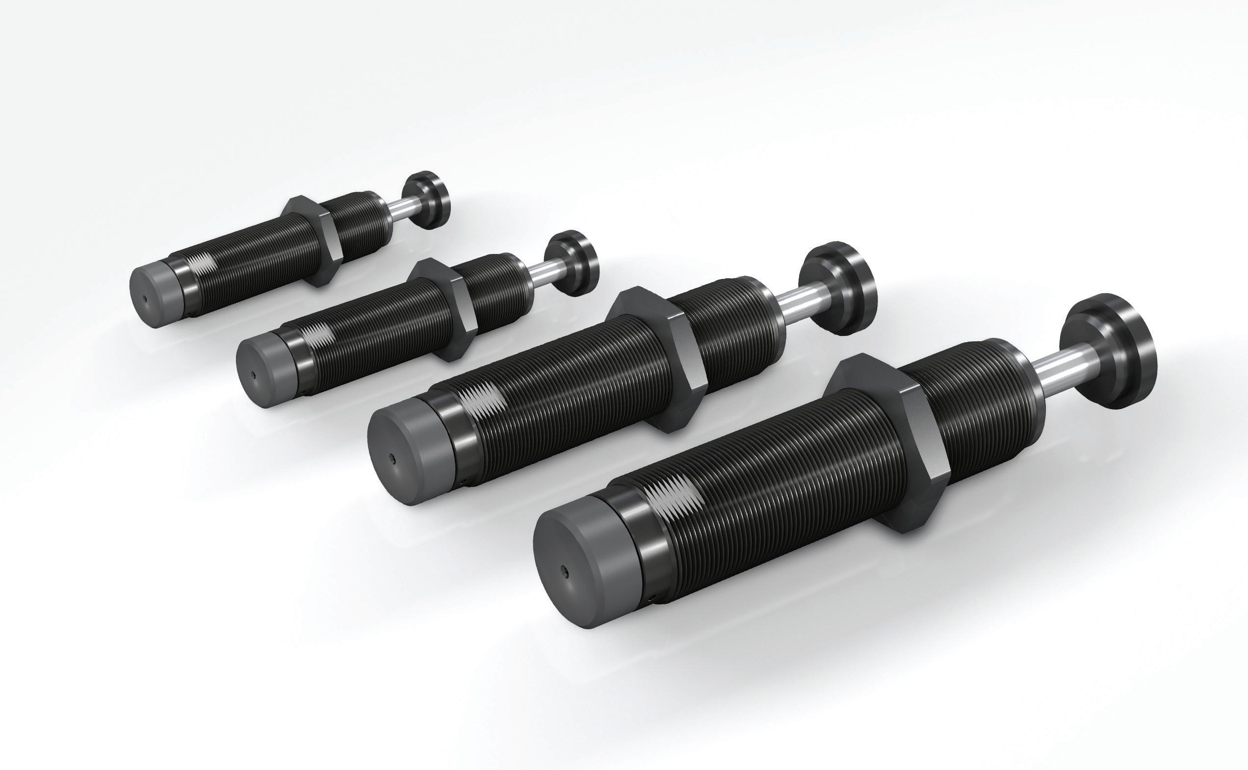

MAIN INTERESTS no longer enough for industrial robots tosimply perform single task. provideintelligent solutions offering simpleapproach to advanced and flexible production.am indispensable in times of considerablechange by helping my employers evolvetowards increased diversification reducedto market.Vernon Hills, Illinois BA in Robotics, summa laude Candy How to Hire an Industrial Robot
AD-VH-00147
Quality Performance Compatibility Meet your new “hire”! https://go.meau.com/HireRobotDW2208P
WORK EXPERIENCE SCARASERIES RH-FRH WORK EXPERIENCE Apple Picker Candy
VernonMitsubishiPackagingMaterialAssemblyPickerExperienceHandlerExperienceUniversity,Hills,Illinois
Download the FREE eBook Mitsubishi Electric is committed to solving your everyday business challenges, no matter how big or small.
ASSISTA COBOTSERIES MELFA QUALIFICATIONSASSISTA My reach and payload are good.can work in hostile environmentscan work like an industrial robot butI can also act like a force-limited cobot MAIN INTERESTS The new series of cobots that can work collaboratively withhumans and offers an intuitive accompanying engineeringsoftware that enables quick and easy start-up.
*Standard warranty is two years, parts only. If the robot is registered through Mitsubishi Electric Automation, it becomes a three year parts and labor warranty. If enrolled in our Robot Diamond Assurance™ preventive maintenance program, it becomes a five year parts and labor warranty.
RESUME
PackagingAssemblyCollaborationsAssemblyPickerExperiencewithHumansExperienceExperienceMitsubishiUniversity,VernonHills,IllinoisBAinRobotics,
QUALIFICATIONS
“HIRE” THE RIGHT ROBOT More Affordable, Capable, and Flexible Our collaborative and industrial robots keep workers safe, are easy to program, and are covered for up to five years with a parts and labor warranty.* Read our free eBook, How to Hire an Industrial Robot, to learn about the process of introducing robotics to your facility, common pitfalls to avoid, as well as use cases and selection recommendations.
I’m very affordable I’m easy to understandbecause I’m pretty basic.I’m slim and compact so canfit in small spaces. am very fast need a conveyor to hold fourhours of parts. can work in an industrialenvironment ...unless it’s verydirty.
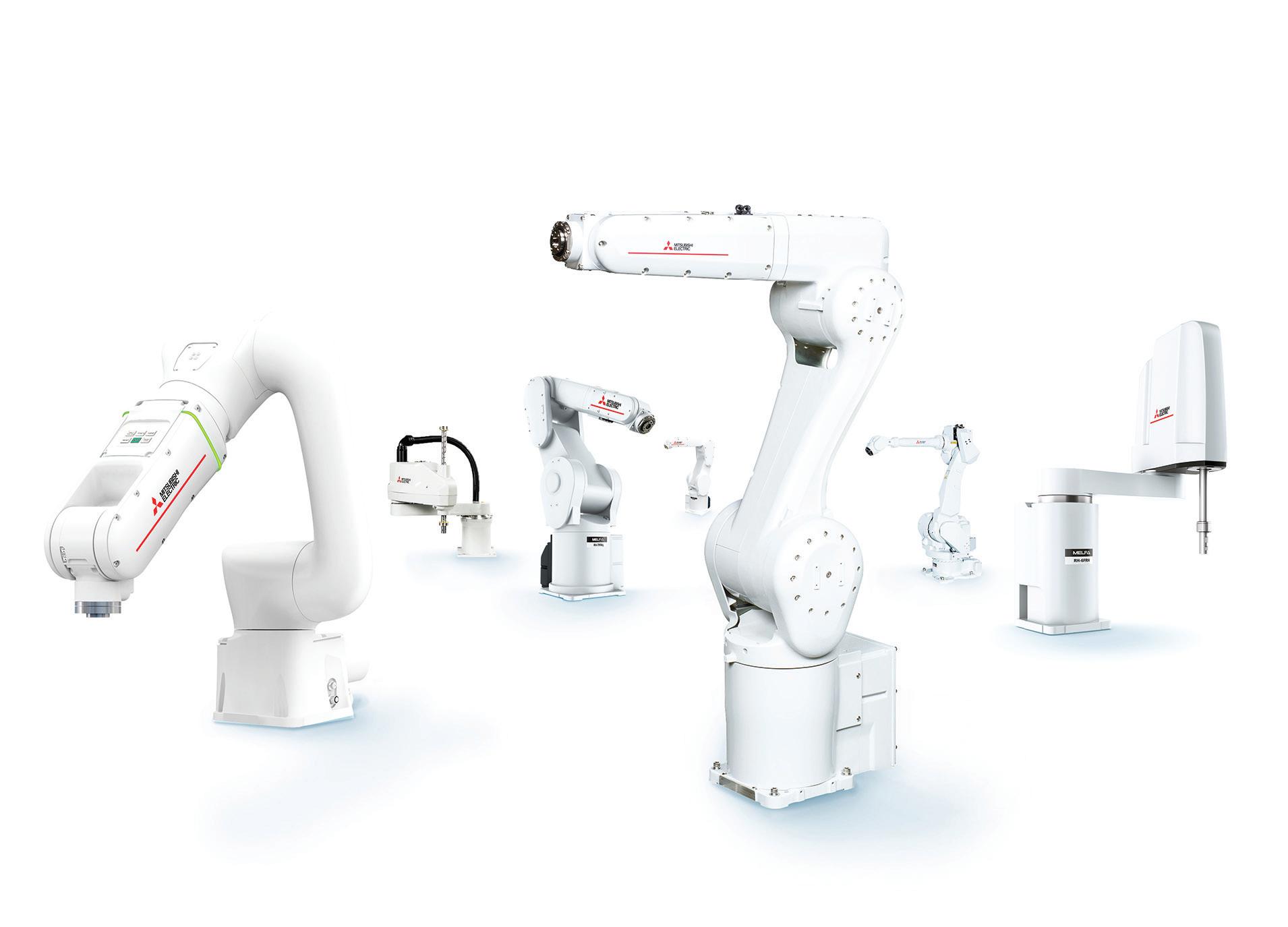


Custom pieces of the material work for vibration and acoustic damping and isolation. Sorbothane turns mechanical energy into heat as the material is deformed. Molecular friction generates heat energy that translates perpendicularly away from the axis of incidence. a smaller orifices reign tighter control over the suspension movement. In real-world terms, you’d correctly expect a luxury vehicle to take advantage of the relaxed damping of larger orifice sizes. At the same time, sports cars wish their suspension movement highly damped to more quickly subdue the movement of their stiffer springs. High-performance shock absorbers use much more sophisticated technology than the simple example described above, ignoring modern examples such as magnetorheological dampers.
Elastomer, synthetic and rubber pads damp vibration and isolate shock loads. They come in tubes, bushings, blocks, pads and washers, to work in heavy-duty applications while delivering strong cushioning for cranes, presses, pipelines and bridges; they also excel in vibration reduction for lab and testing equipment and aerospace.
A primary high-performance shock absorber uses a monotube design alongside nitrogen charging, making it a sophisticated hydraulic component. Imagine placing a second floating piston in the space between the primary piston and the cap and then nitrogen charging the volume between the cap and floating piston, much like a piston accumulator. Add fixed flow control valves to each side of the piston, and you have a highperformance shock absorber. The pistons are more complex than the machined round slug used in hydraulic cylinders, using multiple layers, plates and disc valves. Their combination allows different damping rates for compression and rebound while also allowing multistage damping. A low-speed orifice allows easy fluid flow for shallow dips or bumps, providing a gentle ride. When a harsh impact results in rapid movement, the disc valves close to direct fluid through the morerestrictive orifices, attenuating suspension movement more rapidly. Twin-tube shock absorbers previously dominated the market, most notably because they became popular more quickly. Early suspension damping technology used two SORBOTHANE STANDARD PRODUCTS, ABOVE, AND ISOLATION PADS WITH FABRIC, BELOW.
60 DESIGN WORLD — MOTION 8 • 2022 Motion Systems Handbook ACE Controls · Farmington Hills, Michigan www.acecontrols.com • Enhance operator and machine control through the entire range of motion without excess strength • Perfect support of muscle power with forces from 2 to 2,923 lbs. • Stainless steel options for wash down and sterile environments • A variety of accessories allows for universal SPRINGSINDUSTRIALapplicationGASARETHE SMART WAY TO LIFT AND LOWER
ELASTOMER, RUBBER PADS FOR VIBRATION AND SHOCK REDUCING
Rubber-like materials let these padding elements satisfy specific requirements related to natural frequency, load, and area. Because they are soft, they are also forgiving. Predicting the natural frequency of an application lets material manufacturers target known disturbance frequencies to dissipate energy. The lower the ratio of natural system frequency to disturbance frequency, the more it’s possible to isolate problem vibrations. These cushioning plates can protect machinery subsystems against impacts and isolate vibration and structure-borne noise. For example, PAD plates from ACE Controls withstand compressive loads to 10,000 psi or 69 N/ mm2 depending on plate form and size.
Sorbothane (from a company with the same name) is a thermoset that attenuates shock with near-faultless memory. Deformation is elastic and not plastic, so pads of the material reliably return to their original shape.

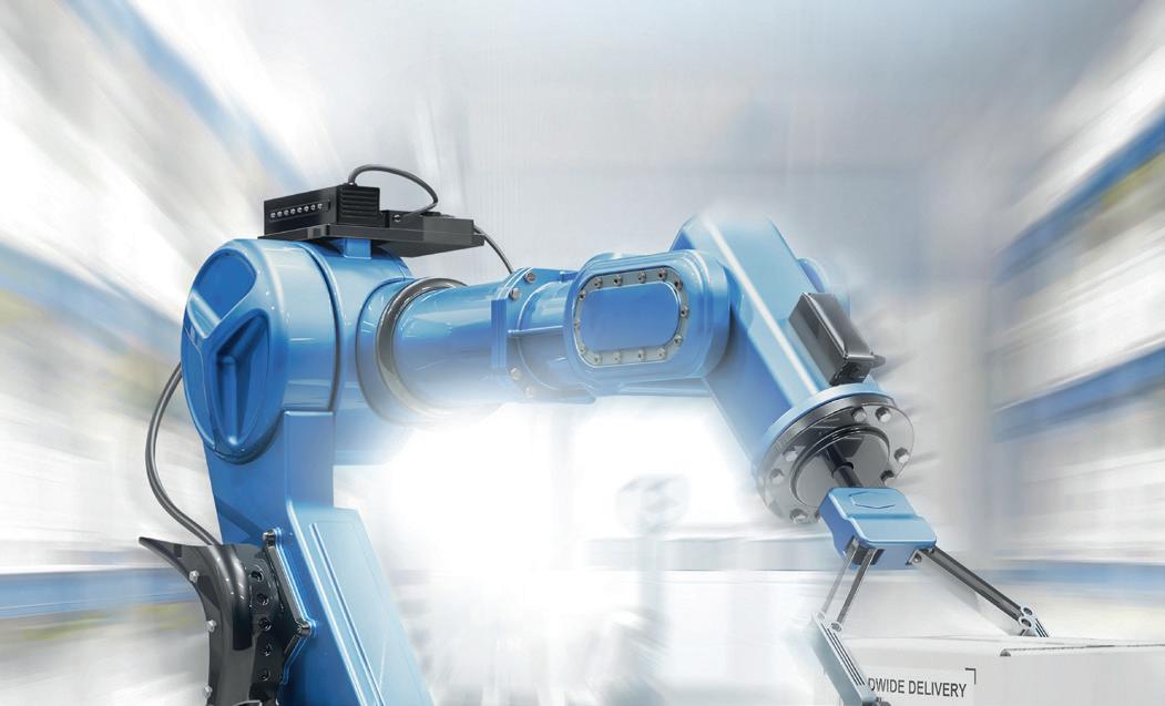


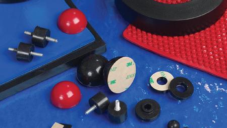
I should mention that shock absorbers cannot simultaneously handle their maximum shock force rating with their maximum acceptable velocity. If you’re unsure, discuss your requirements with your shock absorber manufacturer of choice. Ultimately, automotive and industrial shock absorbers are dynamic orifices designed to transform kinetic energy into heat. That damping may be against an oscillating load or simply one piston compression stroke. Either example offers a peek into yet another fluid dynamic principle that fascinates our industry.
Shock a bers • dampers
Shock absorber applications aren’t limited to automotive applications, of course. Industrial shock absorbers find themselves on material handling applications, trollies, conveyor systems and even amusement rides — machines and applications where a moving object must slow quickly and safely without slamming or bouncing.
Industrial shock absorbers come in downright tiny versions with less than 10-mm bore shock tubes, growing across various sizes and configurations up to 8 in. bore or larger. The smallest examples may absorb loads of 250 lb at a velocity of 50 in./sec or faster (although not simultaneously). Larger bore shock absorbers damp the movement of even the most enormous loads, quickly tackling 200,000 lb of force. Remember that the spring installed with the shock does the heavy lifting to handle a high load, and the shock absorber itself simply damps the motion of the spring.
sorbothane.com 800.838.3906 SORBOTHANE ® MADE IN THE U.S.A. PROVEN SHOCK, VIBRATION & NOISE REDUCING SOLUTIONS MATERIAL SHOCK & VIBRATION INNOVATING SOLUTIONS Online Design Guide Calculators for working with Sorbothane Sorbothane_DesignWorldAd_8-2020_A.indd 1 8/18/20 11:25 AM 61DESIGN WORLD — MOTION
Finally, when only the last orifice remains open, the load should have slowed proportionately relative to stroke length, and combined with the increased spring force, the load will stop.
Industrial shock a ber construction The construction of industrial shock absorbers differs slightly from those used in automobiles. Both designs use orifices to meter the flow of oil, although where the oil is metered varies by design. The more popular multiple-orifice shock absorber uses an ingenious yet simple method to increase the damping response sequentially as the device nears its bottom position. The shock tube equivalent to the pressure tube used in automotive looks similar until you discover the orifice drillings in the shock tube itself. Rather than equip disc valves and axially aligned drillings, the industrial shock absorber uses orifices along the tube length to increase damping force inversely proportional to the stroke length. For example, assume the tube has four drillings along its length, evenly spaced between the piston’s retracted position and the cap. Then, as the load compresses the shock absorber assembly and the piston travels down the length of the shock tube, fluid exits all four orifices under pressure, where a relatively light damping action takes place. The piston covers the hole and continues past the first orifice, reducing the flow potential across the combined orifices. As a result, the shock absorber slows further with only three holes to pass pressurized fluid. The same effect occurs as the piston covers the second orifice, leaving only two left to evacuate fluid, once again reducing the velocity of the piston.
• gas springs
An ideal shock absorption damping rate is linear and should neither bounce off the rod end nor slam down against the shock absorbers’ bump stop. The deceleration rate should appear on a graph as a 45° downward slope with the initial velocity at the top and dead stop at the bottom. Without using the shock’s full stroke, you’re damping too quickly or not quickly enough. The shock absorber should come to a rest near (but not at) the bottom of the stroke.
leather-covered sleaves mounted one inside the other, and clamping devices allowed mechanics to increase the friction as the assembly wore. Not a sophisticated component, modifications to its design led to the twin-tube shock absorber, where a valve assembly was added to the piston and the cap of the primary tube. Twin-tube shocks were also popular because of their inexpensive cost to manufacture. Their barrel requires no precision machining, such as on the monotube design. Without a precision-machined tube, the floating piston designed to separate the nitrogen from the oil would have no chance of sealing. The twin tube design was also more prone to aeration as the nitrogen gas could quickly enter the primary tube, although some modern designs now employ a bladder.
Because a shock absorber is a differential cylinder, you fluid power professionals are intuitively wondering where the cap side fluid has gone since you know its larger volume cannot fill the less volume taking up space around the rod. As fluid exits the shock tube, it flows into a cavity between the tube and the primary cylinder.
A hole in the shock tube ports to the rod’s area, so fluid entering there helps prevent cavitation. The rest is absorbed by a foam accumulator and stored until the piston retracts, drawing the fluid out and back into the shock tube.
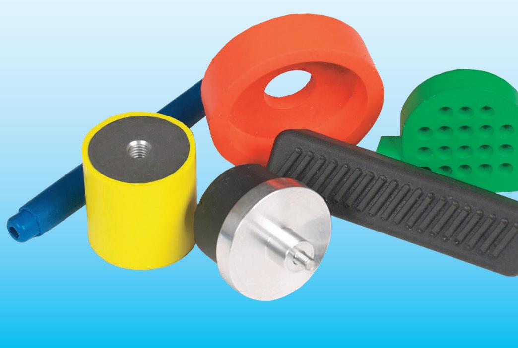
SolutionsDrivenApplication™ Request Samples rotorclip.com Product Focused, Support Driven Reduce Operating Heights By Up To 50% Free Engineering Support: info@rotorclip.com • applicationsThousands+1.732.469.7333ofsupportedDiametersfrom.118"to140"Stainlesssteel&exoticalloysreadilyavailableStandard&customcapabilities


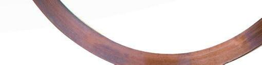

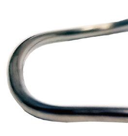


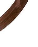
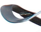
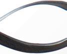
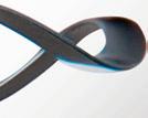


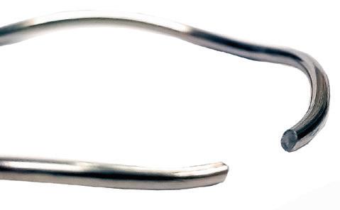
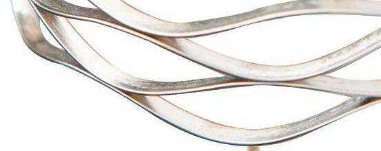


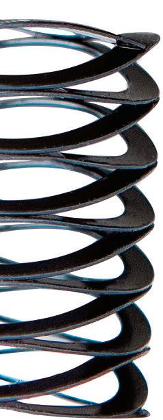

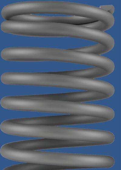
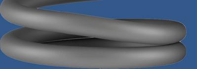
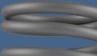


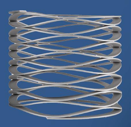


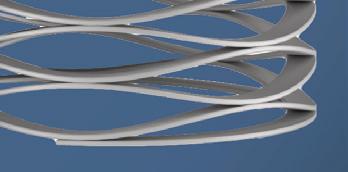


It should be noted that industrial-grade extension springs don’t strictly obey Hooke’s Law because they have some initial tension F1 that must be overcome before any extension takes place. Therefore, a better approximation for the force of an extension spring is F = F1 + kx. The initial tension F1 can be difficult to control and may vary significantly between springs of the same part number. The dimensions of extension springs are normally given in their relaxed state. They may be specified in terms of outside diameter and inside diameter or wire diameter. The length of the body coils may be given in addition to the unloaded length inside the hooks as well as the maximum extended length inside the hooks.
Typically, a sprung steel spring wire is coated with zinc, but stainlesssteel springs are also available. Rubber bands, elastic bands, or bungee cords can provide low-cost alternatives to steel extension springs.
Extension springs can be stretched to increase their length, causing tension force within the spring.
EXTENSION SPRINGS VERSUS TORSION SPRINGS 63DESIGN WORLD — MOTION8 • 2022motioncontroltips.com | designworldonline.com TORSION SPRINGS LIKE THESE ARE COMPONENTS MADE FROM AN ELASTIC MATERIAL THAT (WHEN TWISTED) EXERTS A MOMENT RESISTING THE ROTATION. COMMON TYPES OF TORSION SPRING INCLUDE HELICAL TORSION SPRINGS, TORSION BARS, AND SPIRAL WOUND TORSION SPRINGS. | COURTESY OF DREAMSTIME
Extension springs (or tension springs) are springs that can stretch in length. When extended, these springs are under tension. Typically, each end of the extension spring is attached to a different component and when the components separate, the spring force works to pull them back together. Most extension springs are coiled springs manufactured from sprung steel spring Extensionwire.springs can have a hook or an eye at each end for fastening; variations include open hooks, extended hooks, side hooks, and double full loops.Extension springs are frequently used to create a restoring force in mechanisms such as latches and counterbalances. Because extension springs are under tension, they require no support along their length. This often makes for a mechanism that’s simpler than those based on compression springs.
Springs for motion system applications
Hooke’s law — F = kx — is frequently used as an approximation for elastic objects. It states that the force F required to extend or compress a spring by some distance x is proportional to that distance. The rate that the force increases will depend on the stiffness of the spring stiffness k.
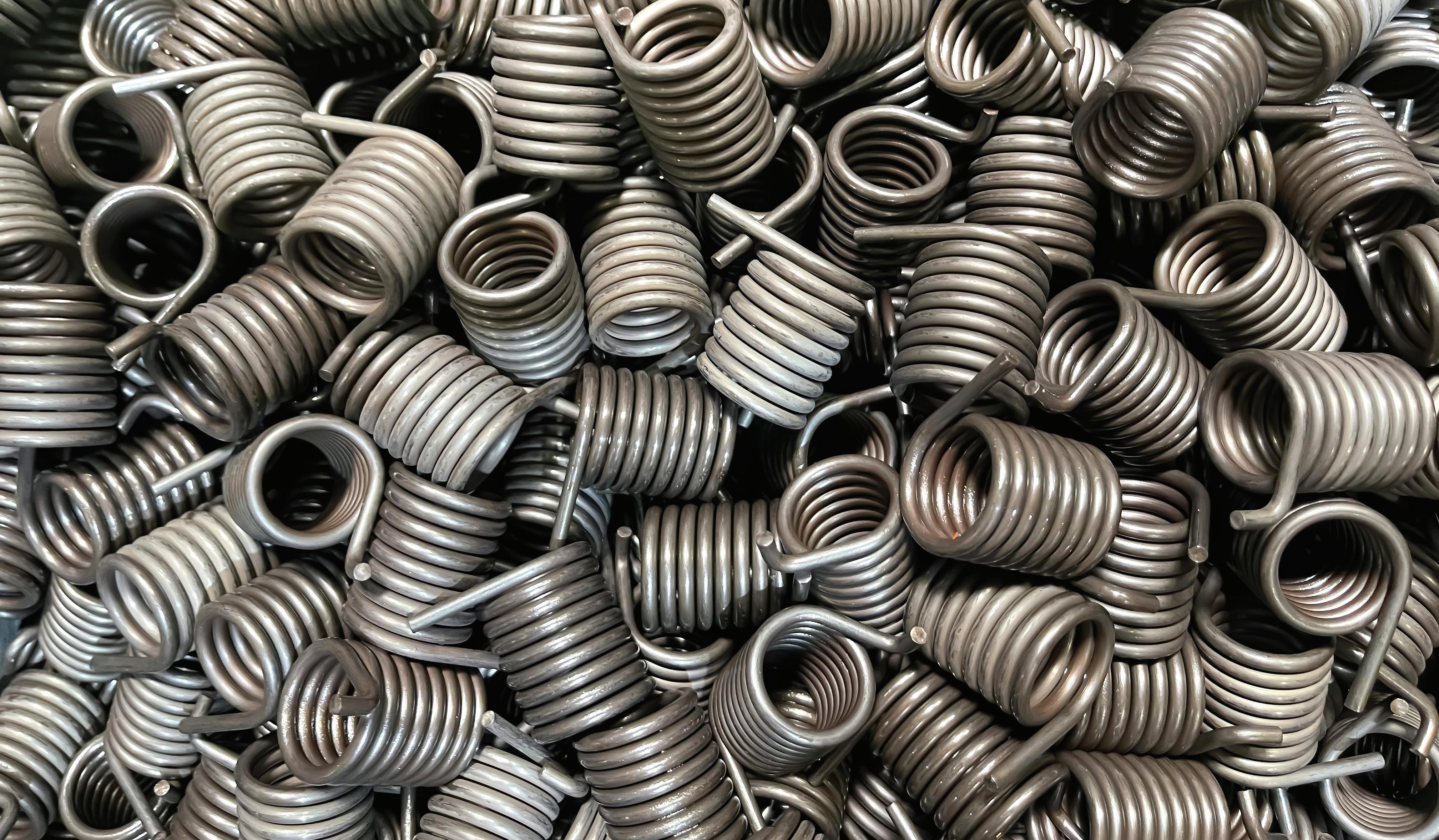
Motion Systems Handbook EXTENSION
Torsion bars are simply straight bars of elastic material that can be twisted to its elastic limit. Torsion bars are typically constructed from steel or rubber. They are often used for heavy-duty applications, such as the suspension of trucks and tanks.
Helical torsion springs are used in a range of applications, with wire diameters ranging from fractions of a millimeter to over an inch. Light-duty torsion springs are typically used as return springs in electrical devices, whereas heavy-duty springs are used in applications such as folding seats and door returns.
| COURTESY
A torsion spring is a component made from elastic material that (when twisted) exerts a moment resisting the rotation. Common types of torsion spring include helical torsion springs, torsion bars, and spiral wound torsion springs.
Torsion bar suspension is extremely durable because of its mechanical simplicity. It is also compact and allows for easy adjustments. Light-duty torsion bars may require tension to generate a restoring torque, which is referred to as a torsion fiber.
A spiral wound torsion spring is formed from a spring wire or (more commonly) a thin strip of sprung steel, coiled into a flat spiral. This configuration allows large angular deflections of many revolutions with relatively little variation in torque during the movement. No wonder spiral-wound torsion springs are used in clockwork devices, clocks, and other devices that require energy to be stored and consistently released.
Helical torsion springs are made from a material, typically sprung steel spring wire, and formed into a helix. At each end, the helix extends to form two straight legs through which the torque is applied. A circular mandrill inside the coil or a circular housing around the coil retains the spring position.
The legs typically extend tangentially, which results in the lowest stresses — though radial and axial legs are also used at times.
Power springs are a specialty type of spiral-wound spring that can exert a consistent torque over many revolutions. They are sometimes referred to as clock springs or motor springs. Power springs are wound tightly within a case to provide particularly high energy density. WORLD — MOTION SPRINGS (OR TENSION SPRINGS) ARE SPRINGS THAT CAN STRETCH IN LENGTH. WHEN EXTENDED, THESE SPRINGS ARE UNDER TENSION. TYPICALLY, EACH END OF THE EXTENSION SPRING IS ATTACHED TO A DIFFERENT COMPONENT AND WHEN THE COMPONENTS SEPARATE, THE SPRING FORCE WORKS TO PULL THEM BACK TOGETHER. OF DREAMSTIME
A single coil version has a single leg extending from each end of a single helix. A double coil version is, essentially, two single coil springs that mirror one another — with the coils concentric but of opposite-handed windings. Both coils are wound from a single length of wire with the two central legs joined in a 180° bend.
SICK OF COIL SPRINGS? Request Free Samples at 847-719-5900 or smalley.com We were too. That’s why we invented the wave spring. • Optimize Application Space & Weight • Industry-Specialized Design Support • Large Selection from Stock • Easy to Customize Crest-to-Crest® Wave Springs 64 DESIGN
Another spring type: T sion springs


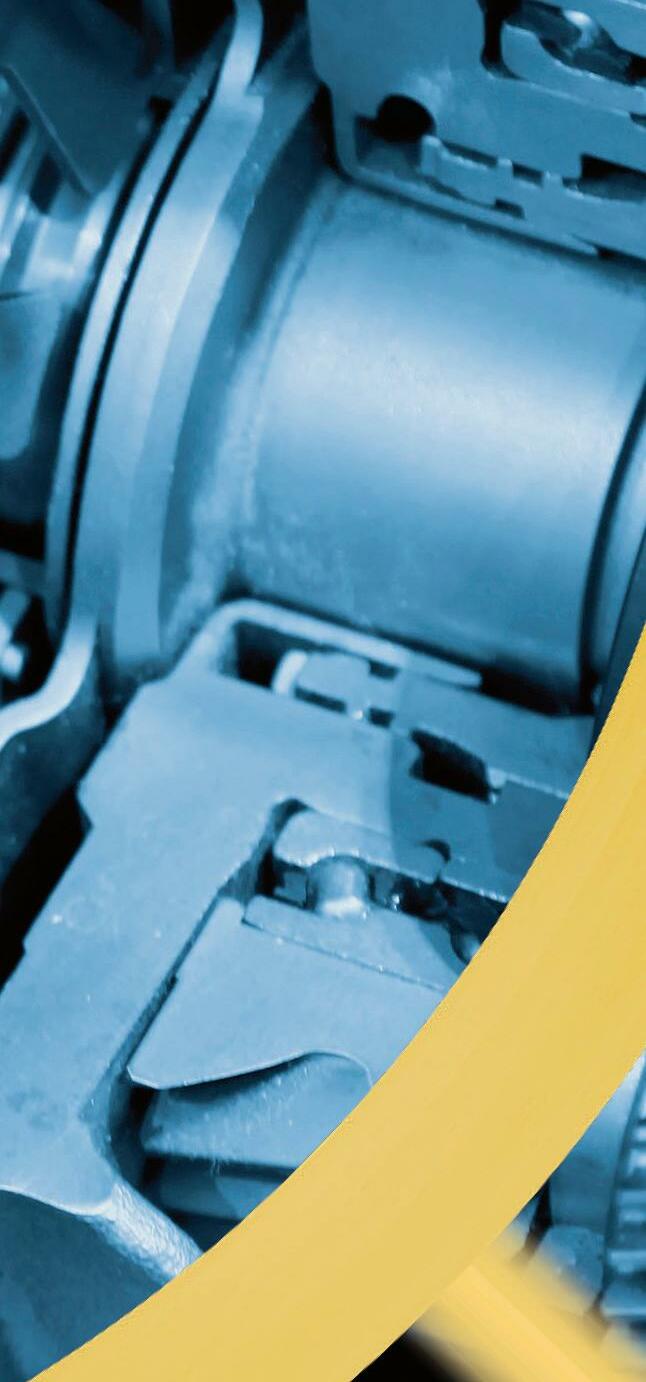


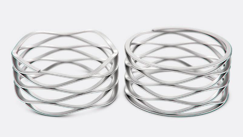

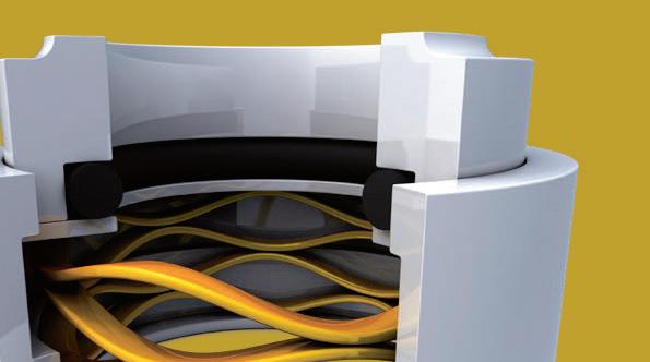

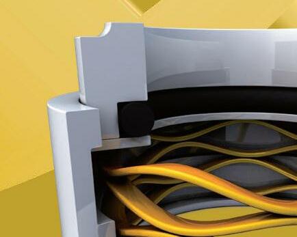
• Miniaturized slotless and coreless motors sporting thumbnail-sized drives and encoders within housings are often no larger than a pencil
• Linear actuators that tightly integrate shape-memory alloys
• Linear stages with linear rails pre-engineered into the build by the supplier
Tables & stages • Cartesian robots • gantries
Top markets f precision and miniature motion Semiconductor manufacture continues to spur many of scaled-down machine designs, along with demand for pocket-sized consumer home products and small appliances with motion functions. Consider the challenging applications of semiconductor manufacturing — including backend wafer inspection. Some operations require motion stages capable of strokes of a few hundred millimeters even while maintaining X and Y-direction accuracy of 1 µm. The extra wrinkle is that some such operations (because of the need for high throughput) must process wafers quite quickly — demanding stage speeds of a couple m/sec along with accelerations to 2 g sans significant vibration in the focal Z axis. No wonder the stage kinematics and heat dissipation capabilities as well as its motion-controller sophistication are all soIncritical.fact,the manufacture of microelectronics and silicon photonics (ICs employing light along nano-optical structures for driving and fast and efficient data transmission) has grown thanks in part to the kinematics and controls advances for ultra-high-precision motion stages. Most of these ultra-high-precision motion stages are pre-integrated, as such systems do two things: They free researchers and manufacturers in demanding fields to focus on core competencies, and they outperform serial-kinematic Cartesian-type robots (often built by end users’ stacking linear stages into XYZ systems). Such Cartesian-type stages typically require additional degrees of freedom — which are often had through still more (bulky and error accumulating) addition of goniometers and rotational yaw, pitch, and roll stages. In contrast, Stewart (hexapod) platforms deliver motion dictated by the controller and not the mechanical bearings and power-transmission linkages. A user-definable rotational center along with lower inertia and higher stiffness are just a few benefits.
A TABLETOP STAGE FOR LIQUID HANDLING AND PIPETTING MIGHT MAINTAIN POSITIONAL ACCURACY TO 50 µm AT SPEED TO 20 MM/SEC WITH A LOAD CAPACITY OF 500 G. WITH HORIZONTAL AND VERTICAL TRAVELS MEASURED IN A FEW DOZEN MILLIMETERS, SOME CONTEXTS MIGHT CLASSIFY THIS AS A MINIATURE MOTION DESIGN … WHILE OTHERS WOULD NOT.
Other examples of pre-integration for compactness abound. No matter how they’re built into systems though, nearly all motion components come in diminutive versions that were unimaginable even a decadeNowago.we’ll cover some of the components that lend themselves to precision multi-axis designs.
Recent decades have seen the unabated spread of automation continues into applications that just a decade or two ago were considered exotic, prohibitive, or downright impossible. Nowhere are the resulting technologies more specialized than those for new nanopositioning and miniature linear-motion designs — where a proliferating array of tiny motors, mechanical components, and especially electronics have enabled nanopositioning and miniature machine designs for specialty workcells, handtools, and mobile robotics. These builds often rely on components pre-integrated into subsystems such as:
• Frameless motors that don’t come with their own housing, but rely on the OEM’s component frame for protection and support
ULTRA-PRECISION ACTUATORS AND MULTI-AXIS STAGES 65DESIGN WORLD — MOTION8 • 2022motioncontroltips.com | designworldonline.com
• Piezo-based hexapods, stages, and other designs sans the unavoidable bulk of copper-wire-based electromechanical actuation


A concurrent trend in medical devices — from medical robots to handpieces to implantables — is that they’re ever smaller and more compact. So medical continues to adopt technologies from consumer electronics and the small motor-driven designs they enable.
.com |
Perhaps the next-biggest driver of miniature motion designs (after the semiconductor industry) is the medical-device industry … a trend likely to grow as COVID demands creative new approaches to medical manufacturing, distribution, and treatment — including more emphasis on automated statusmonitoring systems, distributed laboratory operations, and home healthcare.
The medical-device industry necessitates an array of miniature motion designs. Complicating matters is how FDA requirements on medical-device makers and their suppliers continue to include actuator and motor manufacturers in regulatory scrutiny, so controls on design processes continue to tighten — usually as reverification of production lines and test equipment. Overseas competition, medical-device taxes, and withering Medicare reimbursements are also forcing lower costs for devices and the motors for these applications.
The piezoelectric micromotors in these hexapods are complemented by miniature bearing assemblies, motor mounts, flexures, spring preloads, and miniature drive electronics to cancel hand-tremor movements during the use of microsurgical tools.
In fact, the six-DOF technology delivers enough precision to drive handheld surgical tools, biometric identification, and in-vitro diagnostics. Some dc motors with diameters of just a few millimeters now have enough power density and reliability to satisfy technical and regulatory requirements for implantable pumps to treat an array of conditions.
Case in point: To address the issue of outer axes causing a moment load on the inner axes, certain gantry systems use two X axes or (in some cases) two Y and two Z axes. Gantries almost always have three axes … X, Y, and Z. The load on a gantry system is located within the gantry’s footprint and the gantry is mounted over the working area. However, for parts that cannot be handled from above, gantries can be configured to work from below.
Elsewhere, miniature motion designs automate processes that surgeons still do manually. Consider an implant procedure in which a doctor must physically turn a knob to locate and move a device inserted into a patient’s body. Now, automated motion systems integrating tiny gearmotor, leadscrew, and nut can execute such tasks more precisely.
Case in point: Bean-sized mechatronic hexapods employing piezomotors under closed-loop control are indispensable in motioncontroltips designworldonline lens-focusing functions of consumer and smartphone-grade cameras and UAVs.
Motion Systems Handbook 66 DESIGN WORLD — MOTION 8 • 2022
Of course, such tools must be extremely small and sterile and (because they’re single use) must be Anotherinexpensive.application example demanding increased power density and miniaturization is brushless dc cannulated gearmotors — those with gearbox-motor combinations that (among other things) allow for inline driving of Kirschner wires and pins in orthopedic surgery. Demand for cannulated gearmotors is rising as orthopedic-drill designers are looking to decrease their designs’ overall size. Where applications require tight integration (as for handheld or mobile designs) shrinking semiconductor sizes have let miniature-component suppliers integrate eversmaller drives and controls into smaller and
ALONG WITH INSPECTION, TEST AND MEASUREMENT, AND METROLOGICAL EQUIPMENT, AEROSPACE TOO CONTINUES TO REQUIRE PINT-SIZED DESIGNS FOR MAXIMAL EFFICIENCY AND FUNCTIONALITY.
SOME SERIES OF MINIATURE PROFILED RAILS HAVE RAIL WIDTHS OF JUST A FEW MILLIMETERS OR SMALLER AND TWO ROWS OF RECIRCULATING BALLS. THIS ONE ALSO HAS ENCODER FEEDBACK.
Another option in some instances are ultra-precision motion stages with clever kinematics for well-placed centers of gravity and optimized system dynamics.
.com
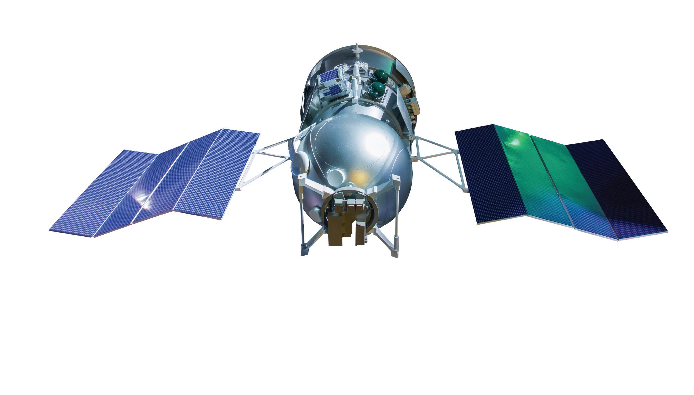
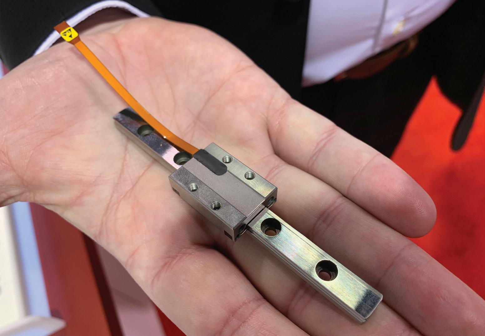
Whileeffectiveness.themachines and devices get smaller, in many cases they must also be increasingly precise. Consider the interest in making more inpatient procedures into outpatient procedures. To this end, surgeons are now using robots or motor-assist tools to boost accuracy. Even risky forms of eye and brain surgery now rely on motor-driven automation to let doctors treat diseased areas in the body while avoiding healthy tissue.
motioncontroltips.com designworldonline.com smaller motors for top reliability and cost
|
Tables & stages • Cartesian robots • gantries 67DESIGN WORLD — MOTION8 • 2022
The medical industry is also prompting electric-motor innovation for smaller and less costly designs. For example, motor-driven tools in operating rooms must draw low voltage and be quiet. Here, traditional peristaltic pumps can be noisy, especially when they’re in a bank or driven by brush motors. Some manufacturers have addressed the problem with alternative dc-motor designs paired with quiet planetary gearing. Another example is portable oxygen concentrators that demand long life because they run off batteries. Miniature motion designs in these are increasingly efficient and power dense as well. Caveat on motionindustry terminology The motion-control industry (like any) has its own system of terminology and naming conventions. The nomenclature for motion components and technologies are highly dependent on the discrete-automation market and equipment type at hand. Where nanopositioning or miniature design is not specifically mentioned, design engineers should assume that traditional definitions (associated with more mainstay machine builds) apply. In fact, even the term miniature can refer to components and systems in a broad range of footprints. Other potentially ambiguous motion-industry designations that rely on context include heavy duty, corrosion-resistant, and high speed. Linear-actuator manufacturers do in fact follow some loose guidelines when classifying and marketing their actuators as high speed. These guidelines are typically based on the drive mechanism, actuator type, and even primary use or industry. But those definitions of high speed lose their relevancy in micro and nano-positioning applications — for which the actuators of choice are often voice coil or piezo technologies. Ultrasonic piezo actuators can reach speeds of 0.5 m/sec or greater, but they typically have maximum strokes of 100 mm or less. Voice-coil actuators operate at speeds to 2 to 3 m/sec with strokes that are typically to 150 mm … although some variations have strokes to beyond 250 mm. These specifications may not fit the general industry definition of highspeed linear actuators. That said, considering the rapid acceleration required to reach these speeds in very short stroke lengths, piezo and voice coil designs are certainly classifiable as high-acceleration actuator options.
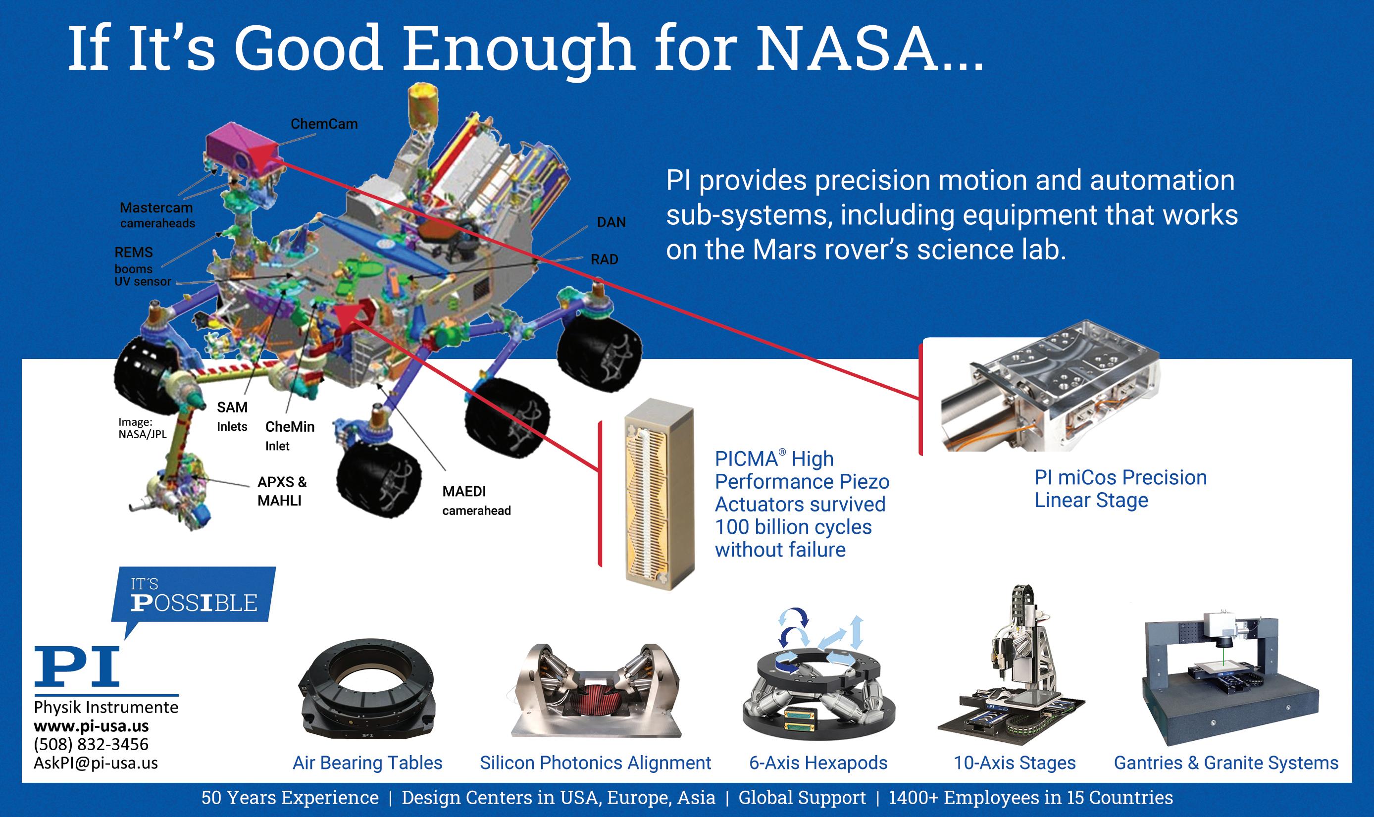
68 DESIGN WORLD — MOTION 8 • 2022 motioncontroltips.com | designworldonline.com Ad Index MOTION SYSTEMS HANDBOOK 2O22 Ace Controls 60 Aerotech .......................................................................... 32 AllMotion 4 CanonBodineBisonBeckhoffAutomationDirect...............................................................1AutomationIBCGear44ElectricCompany7U.S.A.,Inc.57 CGI Inc. ........................................................................... 38 Chieftek Precision 49 Clippard .......................................................................... BC CMT 15 Del-tron 51 Diequa ............................................................................. 43 Digi-Key Electronics 3 Encoder Products Company ............................................. 34 FESTO 23 GAM 41 HELUKABEL USA 19 igus 11 Intech ............................................................................... 40 Lee Linear (PBC) 13 maxon .............................................................................. 55 Mitsubishi Electric Automation 59 mk North America, Inc. 25 NBK America LLC ............................................................. 28 New England Wire & Tubing Technologies 21 NSK .................................................................................. 53 Parvalux 45 Phd .................................................................................. 50 PI (Physik Instrumente) LP 67 POSITAL FRABA 35 Pyramid Inc ...................................................................... 16 Renishaw 36 Rotor Clip..............................................................Cover, 62 Ruland Manufacturing 27 SEW-Eurodrive 47 Smalley Steel Ring 64 Sorbothane 61 Stock Drive Products/Sterling Instrument ..........................5 THK America Inc. IFC WAGO Corporation ...........................................................9 Yaskawa Electric America 30 Zero-Max, Inc. 2 JamiSALESBrownlee 224.760.1055jbrownlee@wtwhmedia.com Jim Dempsey 216.387.1916jdempsey@wtwhmedia.com Mike Francesconi mfrancesconi@wtwhmedia.com630.488.9029 Jim Powers @jpowers_media312.925.7793jpowers@wtwhmedia.com Courtney Nagle 440.523.1685cseel@wtwhmedia.com Publisher Mike Emich Managing@wtwh_memich508.446.1823memich@wtwhmedia.comDirector Scott McCafferty @SMMcCafferty310.279.3844smccafferty@wtwhmedia.com LEADERSHIP TEAM EVP Marshall Matheson @mmatheson805.895.3609mmatheson@wtwhmedia.com
AT11-20USA productIndividualtransport Free motion6DlayoutsystempayloadScalablekg planarLevitatingmovers upVelocitiesto2m/s XPlanar enables new dimensions of freedom in product and material handling: Levitating planar movers fly over flexibly arranged planar tiles accommodating nearly any track layout and path planning. Individual 2D transport at up to 2 m/s Processing with up to 6 degrees of freedom Transport and processing in one system Wear-free, hygienic and easy to clean Free arrangement of planar tiles enabling totally customized machine and process layouts Multi-mover control enables parallel and individual product handling Fully integrated into the powerful and standardized PC-based Beckhoff control system (TwinCAT, PLC IEC 61131, Motion, Measurement, Machine Learning, Vision, Communication, HMI) For use across all industries: assembly, packaging, food/bev, pharma, laboratory, entertainment, … Flying 2D product transport with up to 6 degrees of freedom : Agile machines with adaptive automation Scan inXPlanarexperiencetoaction


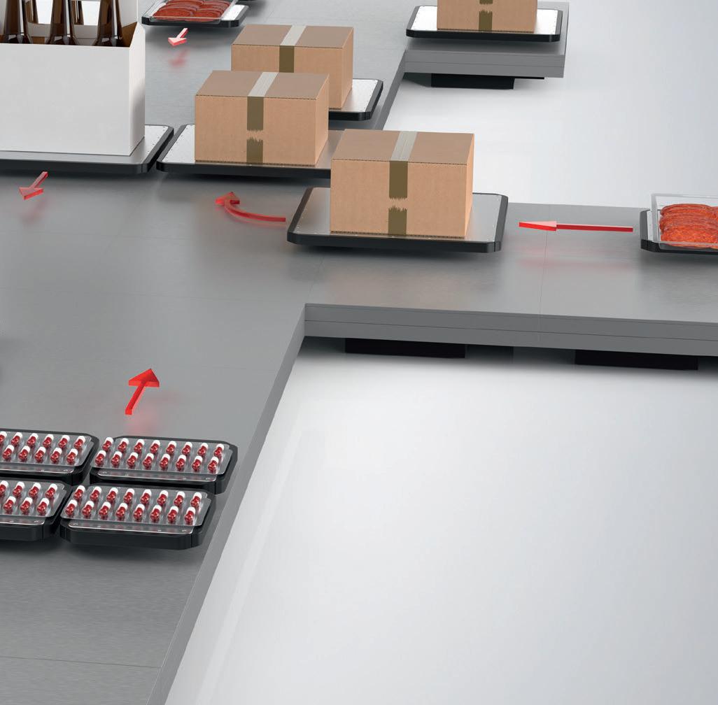


Take Control with Cordis
The
future of proportional control has arrived— and it’s digital. The Clippard Cordis is a revolutionary microcontroller primed for escape velocity from a proportional control market that has grown stagnant. With unparalleled performance and flexibility not possible with current analog proportional controllers, the Cordis makes everything from calibration, to sensor variety, to future development opportunities more accessible and less complicated. Precise, Linear Digital Pressure Control • Resolution ≤5 mV • Accuracy ±0.25% of full scale • Real-time adjustable PID control • Integrated 0 to 10 VDC, 4-20 mA signal, or 3.3 VDC serial communication • 0 to 10 VDC feedback pressure monitor • Virtually silent • No integral bleed required • Multiple pressure ranges from vacuum to 150 psig • 2.7 to 65 l/min flow control 877-245-6247 CINCINNATI • BRUSSELS • SHANGHAI Contact your distributor today to learn more about how the Cordis can provide precise, real-time control for your application, or visit clippard.com to request more information. ELECTRONIC PRESSURE REGULATION