TRANSMISSION POWER GUIDE


DESIGNWORLDONLINE.COM MAY 2023
MOTIONCONTROLTIPS.COM


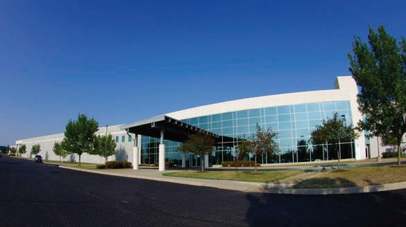
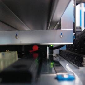
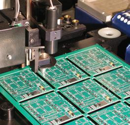
THK is committed to meeting the worldwide demand for linear motion products. We manufacture, assemble, and ship across North America from our location in Hebron, Ohio. We’ve also ramped up our automating processes at existing facilities, including our U.S. manufacturing plant, where over 70% of THK Robotics Components are manufactured. Automated processes at this state-of-the-art facility enable increased production while maintaining the high standard of precision associated with THK products.
To learn more, call us at 1-800-763-5459 or visit www.thk.com.
See us at: Rapid + TCT, Chicago IL, May 2-4 Booth #1634


See us at ATX West, Anaheim CA, Feb. 7 - 9, Booth #4254

Robotics Summit & Expo. Boston MA, May 10-11, Booth #332
Automate, Detroit MI, May 22-25, Booth #5610


THK Manufacturing in Hebron, Ohio
1–2 Week Delivery of Select LM Guides and Actuators

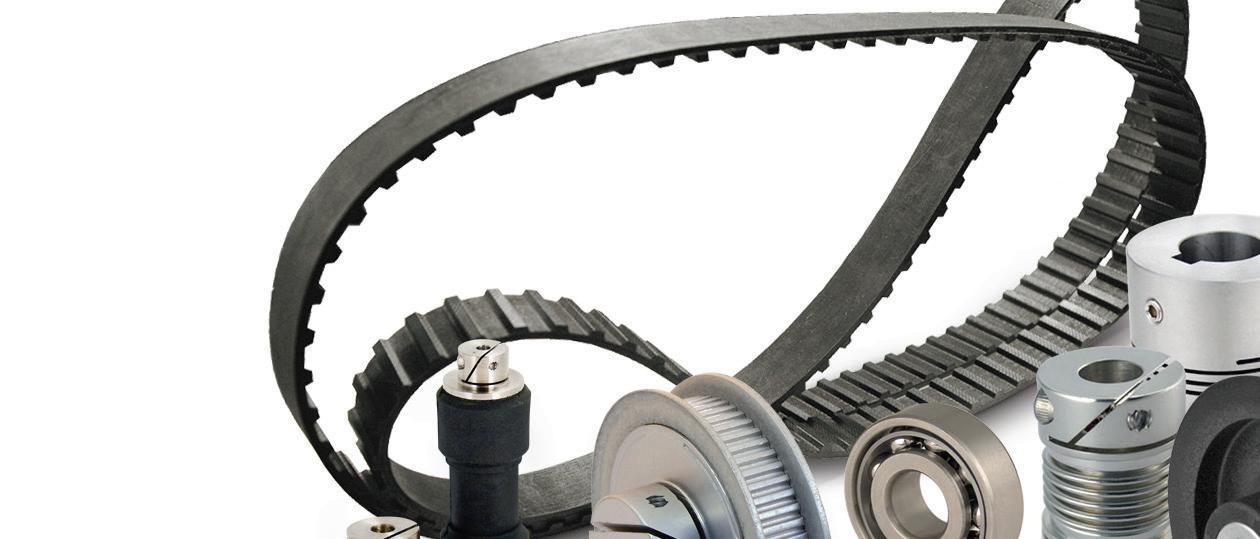
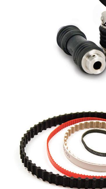
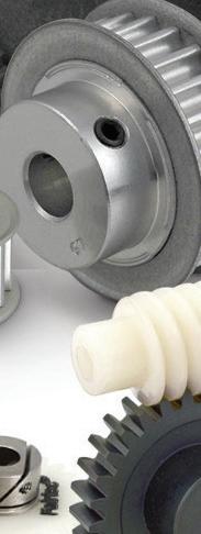
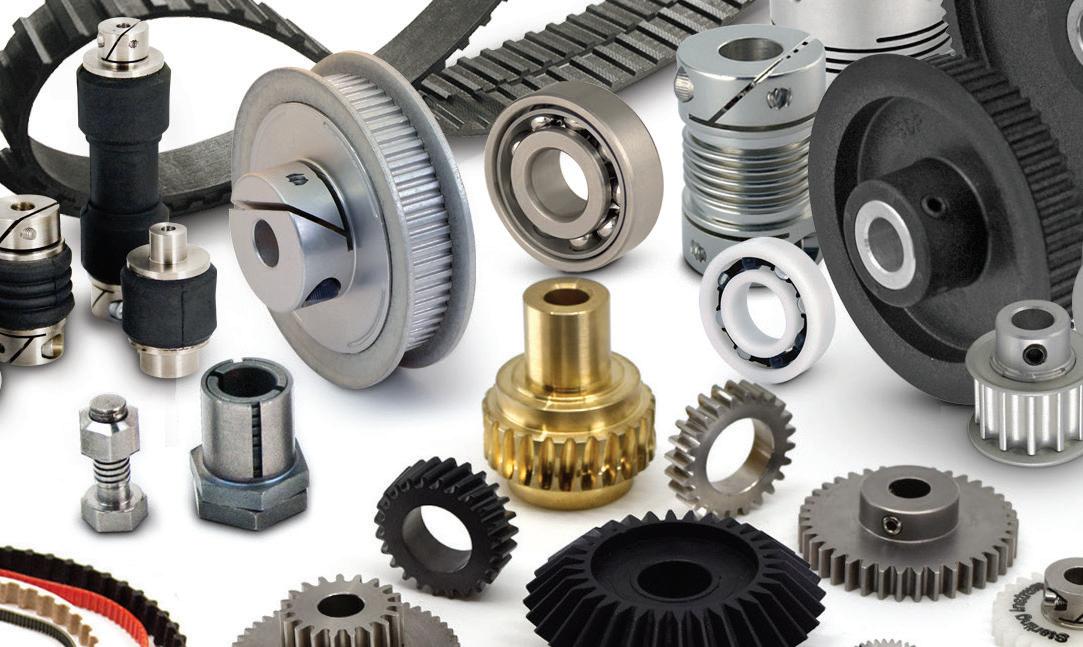
A huge selection of power transmission products, including belts and pulleys STARTING AT ONLY $3.50 (60XL025NG)


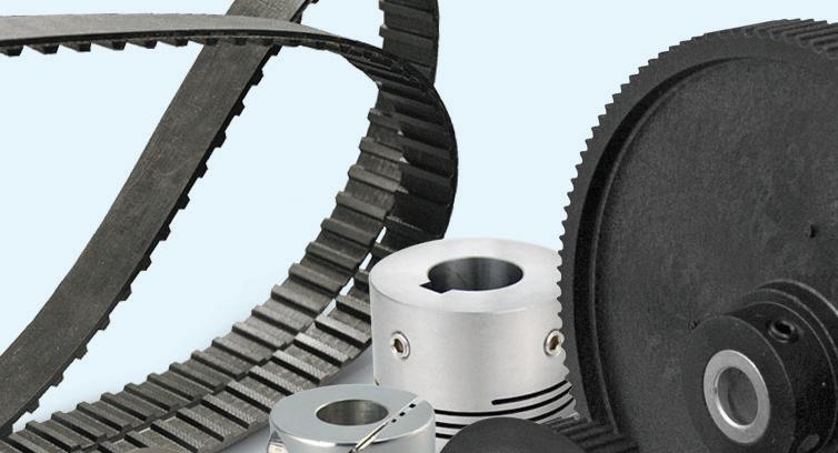
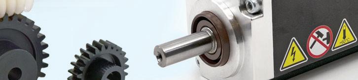
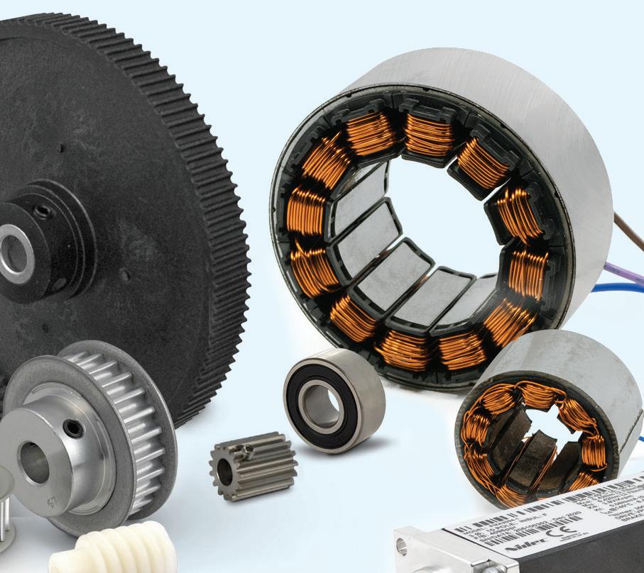
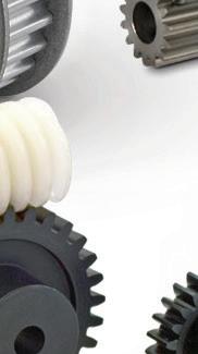
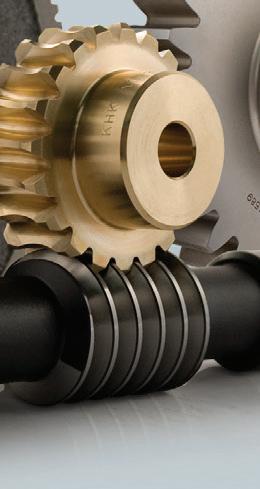
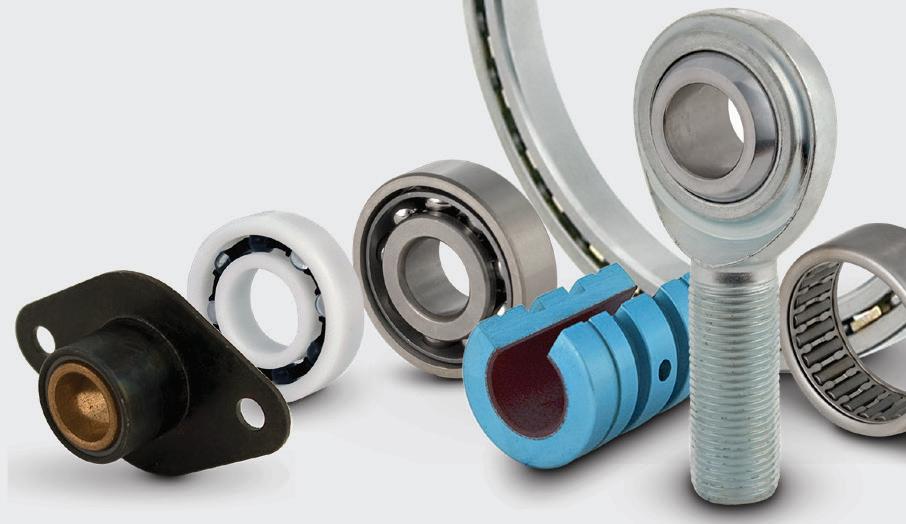
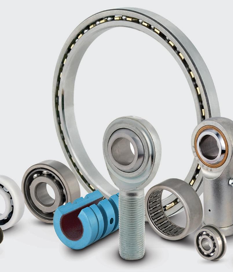
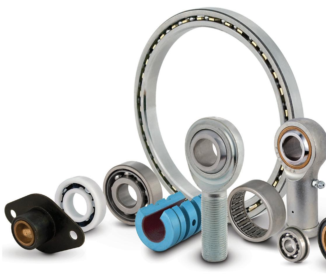
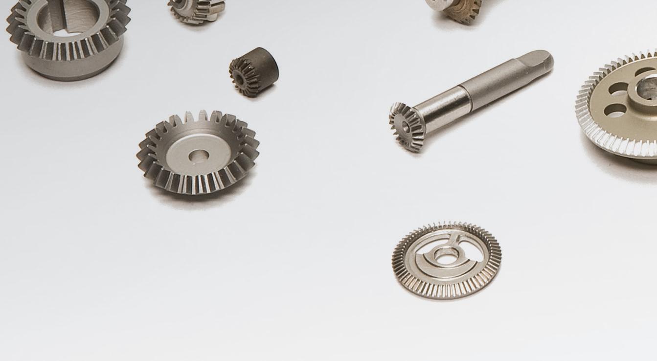
Power transmission products transfer mechanical motion from its source to where it’s needed to perform a task. Most commonly used in mechanical drivetrains to create movement, power transmission products can alter the source motion’s direction, torque and speed.
Available components include:


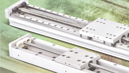
• Linear motion slides and actuators


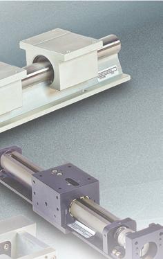

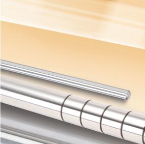
• Linear shafts and shaft supports


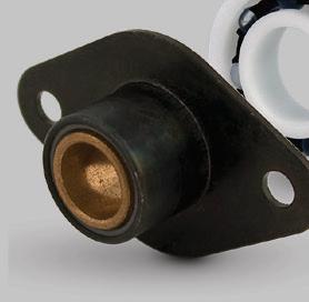
• Polymer bearings


• Cast iron and aluminum general purpose gearboxes with a variety of torques, shaft orientations and gear ratios


• High precision gearboxes


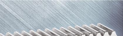
• Rack and pinions
• Linear bearings and rails


• Timing belts/pulleys/bushings


• A host of shaft couplings, bore reducers, and other purely mechanical devices


Welcome to the 2023 edition of Design World’s special Power Transmission Guide.
Each year, the motion editors at Design World prepare four special issues devoted to motion control; one surveying the newest trends in the industry, one spotlighting unique motion applications, and two special issues covering the basics of motion systems more generally. Just as this Power Transmission Guide does here – covering the basics of power transmission by spotlighting basic components such as gears, actuators, motors and other mechanical components.
Why the focus on motion basics? For a number of reasons. First, covering the basics can serve as a good introduction for new engineers just entering the field. Such guides help in introducing basic principles as well as doing a deep dive on some finer grain details of how various components work.
Second of all, presenting the basics of motion can also help established engineers by serving as a refresher on some of the basics they may have forgotten. And let’s be honest; seeing as how humans excel at forgetting things, we can all use a refresher once in a while.
In fact, study after study shows the importance of repetition for learning, whether for tasks involving manual labor (training our so-called “muscle memory”) or learning basic knowledge like multiplication tables. And apparently the opposite holds true, encapsulated in the old cliché of “use it or lose it.”
We can see this play out in basic training and continued learning aimed at keeping one’s skills intact, with first responders such as EMTs and police officers and firefighters constantly practicing and training, learning new skills and techniques but also polishing and honing existing, necessary and crucial ones that are essential for doing their jobs.
Perhaps this is why we’ve invented all sorts of ways to remember and recall and stay sharp; crossword puzzles, sudoku, memory games, including the recent Wordle craze, as well as its geographic counterpart Worldle.
While some of these admittedly are meant to stave off overall cognitive decline by keeping cognitive function sharp, in the technical world such basics and tutorials and refreshers serve to keep one’s technical knowledge current. For licensed professional engineers, there are even requirements for ongoing continuing education. For example, here in the state of Ohio, licensed PEs are expected to complete 30 hours of continuing education credits during each two-year renewal period. This can include technical work as well as ethical and managerial work as well.
In this light, it’s no coincidence that one of the world’s greatest works of philosophy, The Analects of Confucius written more than 2,300 years ago, begins with a series of observations about what is good in human life, including this:
“To learn and at due times to repeat what one has learned, is this not after all a pleasure?”

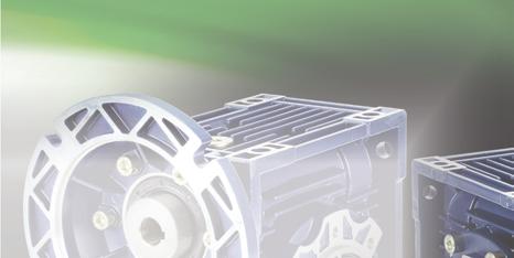
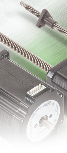
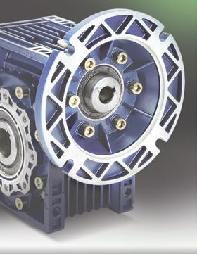
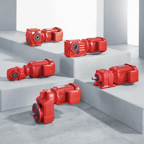
Servo motors and gear units from SEWEURODRIVE offer a high degree of dynamics and performance with a compact design, making them excellent for confined spaces. Multiple frame sizes and torque ratings makes them the perfect fit in material handling, hoist and gantry applications, and a wide variety of
machine automation applications. Their modular design allows for direct gear unit mounting without adapters or couplings. Pair that with the option of single-cable technology and you’ve got a flexible, precise servo drive solution.
8 TRENDS IN DIGITAL MANUFACTURING
12 CONSUMER-PRODUCT PRODUCTION AND DISTRIBUTION LEAD AUTOMATION TRENDS
For the annual Design World Trends issue, dozens of industry experts shared their insights. Here is additional information from some of those experts on the design, manufacture, and distribution of consumer products. Especially since COVID, the manufacture and distribution of home appliances, consumer electronics, and have evolved with advanced automation technologies.
18 FOCUS ON HIGH-SPEED ACTUATORS

2O DIFFERENTIATING BELT-DRIVE TYPES
Synchronous belt drives dominate motion control designs for positioning and other precision functions. Here we detail V belts and other belt types used in industrial, robotic, and consumer designs for both linear and rotary axes.
26 COUPLING BASICS
30 MEASURING POSITION AND SPEED IN MOTION APPLICATIONS
35 GEAR RATIO BASICS
38 GEARMOTORS DRIVING THE TIMBER INDUSTRY
Rugged innovative gears and gearmotors along with other drive technologies rise to the challenge in demanding wood-processing applications.
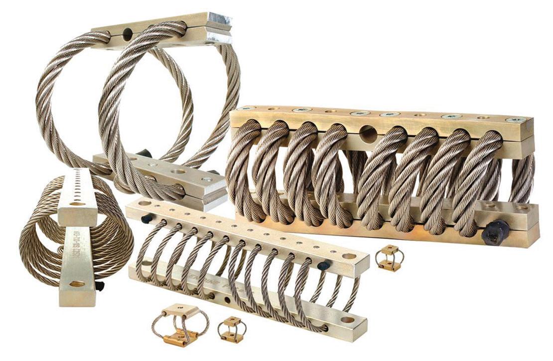
44 BASICS OF SHOCK AND VIBRATION ABSORBERS
47 AS-INTERFACE REDUCES CONTROL-CABINET WIRING
48 AD INDEX
EDITORIAL
VP, Editorial Director Paul J. Heney pheney@wtwhmedia.com @wtwh_paulheney
Executive Editor Lisa Eitel leitel@wtwhmedia.com @dw_LisaEitel
Managing Editor Mike Santora msantora@wtwhmedia.com @dw_MikeSantora
Senior Editor Miles Budimir mbudimir@wtwhmedia.com @dw_Motion
Senior Editor Mary Gannon mgannon@wtwhmedia.com @dw_MaryGannon
Senior Editor Rachael Pasini rpasini@wtwhmedia.com @WTWH_Rachael
Associate Editor Heather Hall hhall@wtwhmedia.com @wtwh_heathhall
IN-PERSON EVENTS

Events Manager Jen Osborne jkolasky@wtwhmedia.com @wtwh_Jen
Events Manager Brittany Belko bbelko@wtwhmedia.com
Event Marketing Specialist Olivia Zemanek ozemanek@wtwhmedia.com
VIDEOGRAPHY SERVICES
Videographer Garrett McCafferty gmccafferty@wtwhmedia.com
Videographer Kara Singleton ksingleton@wtwhmedia.com
CREATIVE SERVICES & PRINT PRODUCTION


VP, Creative Services Mark Rook mrook@wtwhmedia.com @wtwh_graphics
VP, Creative Services Matthew Claney mclaney@wtwhmedia.com @wtwh_designer
Art Director Allison Washko awashko@wtwhmedia.com @wtwh_allison
Senior Graphic Designer Mariel Evans mevans@wtwhmedia.com @wtwh_mariel
Director, Audience Development Bruce Sprague bsprague@wtwhmedia.com
ONLINE DEVELOPMENT & PRODUCTION
Web Development Manager B. David Miyares dmiyares@wtwhmedia.com @wtwh_WebDave
Senior Digital Media Manager Patrick Curran pcurran@wtwhmedia.com @wtwhseopatrick
Front End Developer Melissa Annand mannand@wtwhmedia.com
Software Engineer David Bozentka dbozentka@wtwhmedia.com
Digital Production Manager Reggie Hall rhall@wtwhmedia.com
Digital Production Specialist Elise Ondak eondak@wtwhmedia.com
Digital Production Specialist Nicole Johnson njohnson@wtwhmedia.com
WTWH Media, LLC
1111 Superior Ave., Suite 2600 Cleveland, OH 44114
Ph: 888.543.2447
FAX: 888.543.2447
MARKETING
VP, Digital Marketing Virginia Goulding vgoulding@wtwhmedia.com @wtwh_virginia
Digital Marketing Manager Taylor Meade tmeade@wtwhmedia.com
@Taylor Meade Digital Design Manager Samantha King sking@wtwhmedia.com
Marketing Graphic Designer Hannah Bragg hbragg@wtwhmedia.com
Webinar Coordinator Emira Wininger emira@wtwhmedia.com
FINANCE
Controller Brian Korsberg bkorsberg@wtwhmedia.com
Accounts Receivable Specialist Jamila Milton jmilton@wtwhmedia.com
PRODUCTION SERVICES
Customer Service Manager Stephanie Hulett shulett@wtwhmedia.com
Customer Service Representative Tracy Powers tpowers@wtwhmedia.com
Customer Service Representative JoAnn Martin jmartin@wtwhmedia.com
Customer Service Representative Renee Massey-Linston renee@wtwhmedia.com
Customer Service Representative Trinidy Longgood tlonggood@wtwhmedia.com
DESIGN WORLD does not pass judgment on subjects of controversy nor enter into dispute with or between any individuals or organizations. DESIGN WORLD is also an independent forum for the expression of opinions relevant to industry issues. Letters to the editor and by-lined articles express the views of the author and not necessarily of the publisher or the publication. Every effort is made to provide accurate information; however, publisher assumes no responsibility for accuracy of submitted advertising and editorial information. Non-commissioned articles and news releases cannot be acknowledged. Unsolicited materials cannot be returned nor will this organization assume responsibility for their care. DESIGN WORLD does not endorse any products, programs or services of advertisers or editorial contributors. Copyright© 2023 by WTWH Media, LLC. No part of this publication may be reproduced in any form or by any means, electronic or mechanical, or by recording, or by any information storage or retrieval system, without written permission from the publisher.
Subscription Rates: Free and controlled circulation to qualified subscribers. Non-qualified persons may subscribe at the following rates: U.S. and possessions: 1 year: $125; 2 years: $200; 3 years: $275; Canadian and foreign, 1 year: $195; only US funds are accepted. Single copies $15 each. Subscriptions are prepaid, and check or money orders only.
Subscriber Services: To order a subscription or change your address, please email: designworld@omeda.com, or visit our web site at www.designworldonline.com
POSTMASTER: Send address changes to: Design World, 1111 Superior Ave., Suite 2600, Cleveland, OH 44114


Materials of: CARBON, ALLOY and HARDENED ALLOY STEELS
Materials of: ALLUMINUM and CORROSION RESISTANT STEEL
WHITTET-HIGGINS manufactures quality oriented, stocks abundantly and delivers quickly the best quality and largest array of adjustable, heavy thrust bearing, and torque load carrying retaining devices for bearing, power transmission and other industrial assemblies; and specialized tools for their careful assembly.
Visit our website–whittet-higgins.com–to peruse the many possibilities to improve your assemblies. Much technical detail delineated as well as 2D and 3D CAD models for engineering assistance. Call your local or a good distributor.
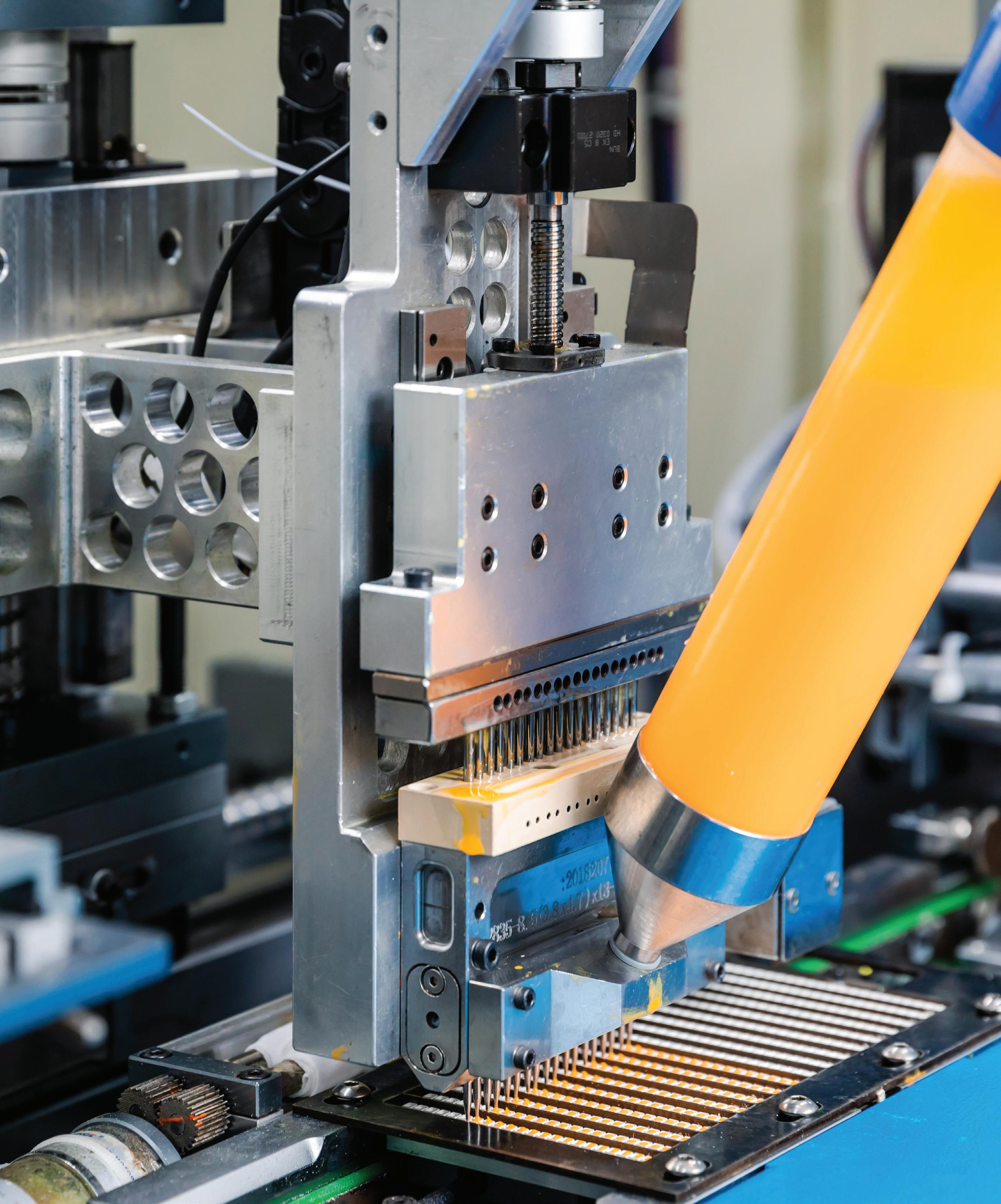
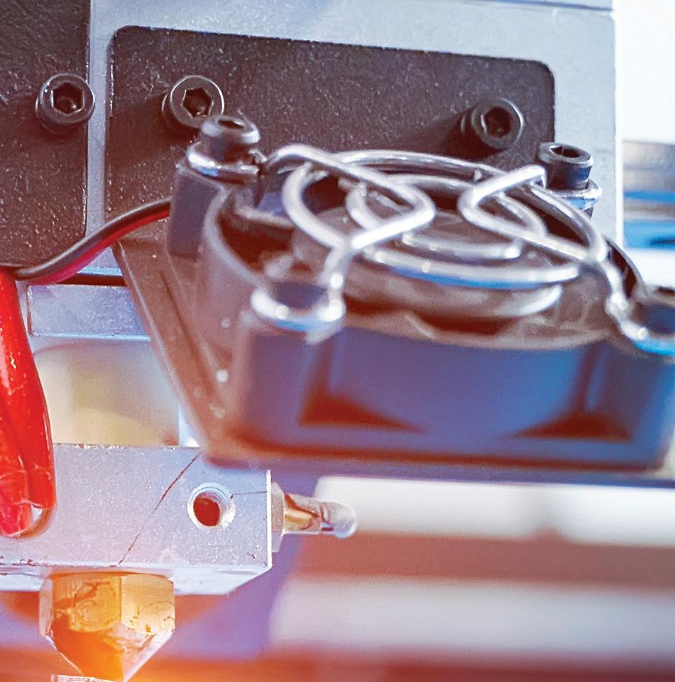
The convergence of software, cloud computing, and additive manufacturing (3D printing) technologies has given manufacturers the ability to cost-effectively supply millions, thousands, or dozens of a given workpiece — and even batch sizes down to one. It’s no wonder that worldwide, batch sizes have in fact shrunk ‚ catering to increased demand for customized products‚ and additive manufacturing has played a role in this trend. To be clear, this has vaulted additive manufacturing into a realm far beyond its hobbyist and rapid-prototyping origins.
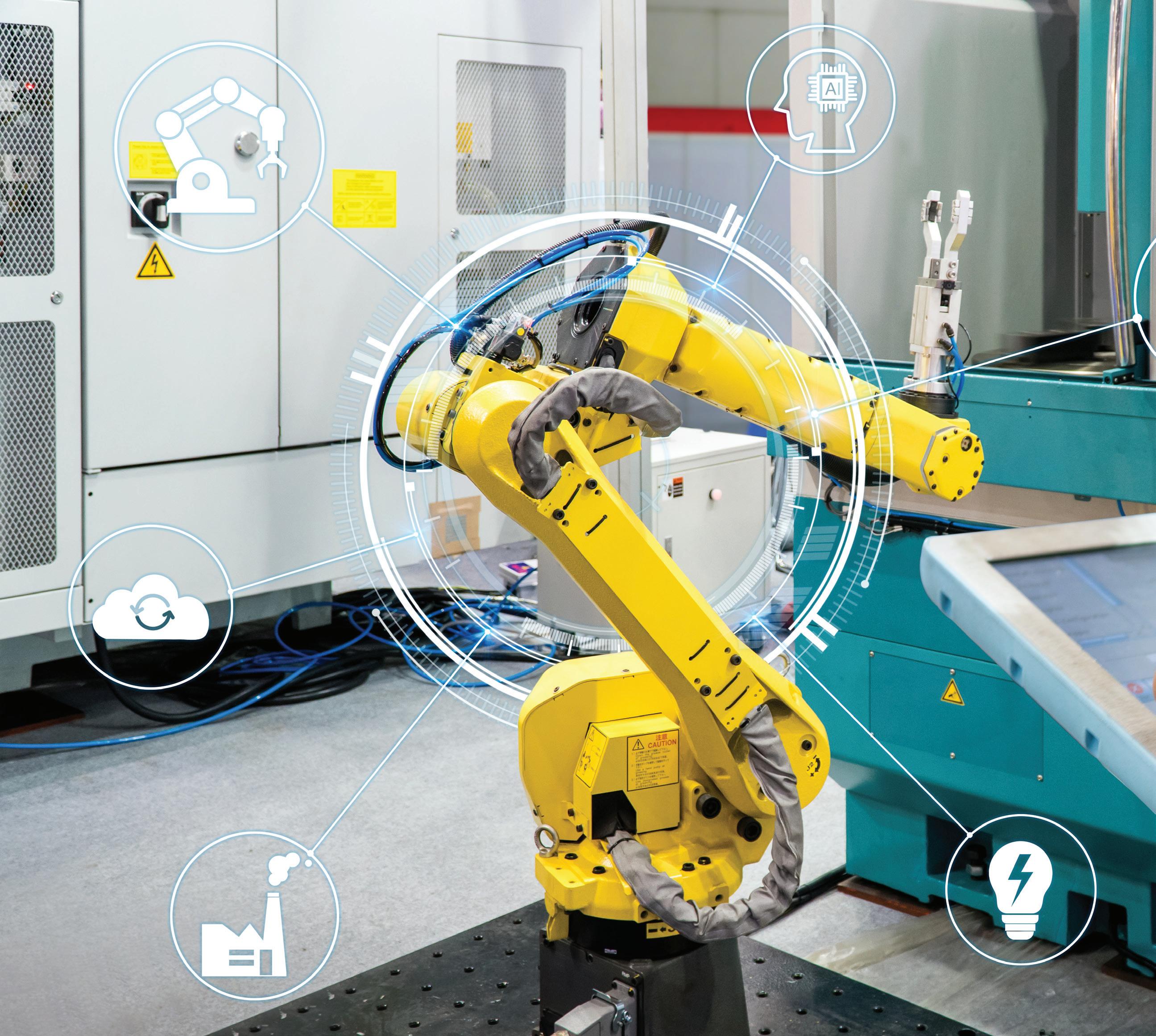
Digital manufacturing adoption accelerated during the COVID-19 pandemic and continues to increase as supply-chain and labor-shortage issues persist.
(Image
So today, manufacturing relies on additive manufacturing as well as traditional machining and injection molding incorporating software and other digital tools for top flexibility and efficiency. Even legacy machine-tool equipment has become increasingly retrofitted to accept instructions in digital formats to execute the production of workpieces. Injection molding is less digitized than the machine-tool industry, but software-centric approaches have made inroads here as well. Interestingly, digitally driven additive manufacturing is the perfect solution for the rapid production of injection-molding fixtures and jigs. This is just one example of cross-pollination between the various branches of digital manufacturing.
The COVID-19 pandemic has only hastened adoption of digital-manufacturing approaches in the U.S. Consider how many manufacturers relying on Chinese production facilities saw their supply chains negatively affected by shipping and transportation slowdowns in 2020 only to see more challenges in 2021 and 2022 caused by rolling regional manufacturing shutdowns arising from stern governmental attempts at completely containing the COVID virus. For some companies with digital-manufacturing capabilities, rerouting the production of key parts to other regions of the world can be triggered with a click of a button. Those with connectedenterprise capabilities integrating transportation and logistics are most nimble of all.
For the 2023 Design World Trends issue, the editors asked industry experts to comment on these digital-manufacturing developments. Here’s what the sources had to say.
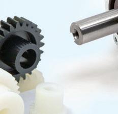
Gallant: We’ve added minor 3D printing to our suite of design services — more specifically, to help streamline customers’ R&D processes. We manufacture dc motors and gearmotors for the motion control world, and 3D printing helps us provide accessories such as mounting brackets, gears, motor holders, and enclosures. This way, accessories are correctly sized to fit our motor solutions so the customer can get started on their prototyping that much quicker. Once a design concept is finalized, we can then turn over the design to our injectionmolding experts for mass production.
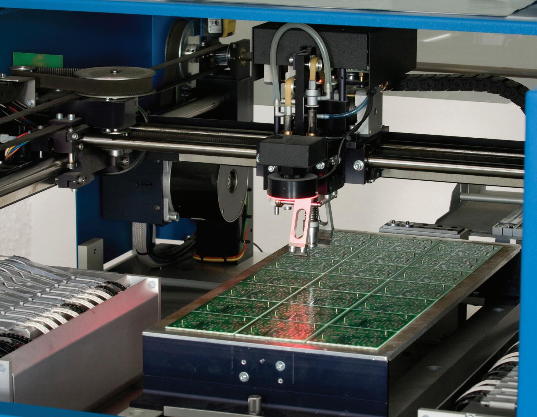
Luchars: We use software to scale hardware solutions that can be manufactured anywhere in the world. To accomplish this, ECM pairs PCB Stator printed circuit boards with our PrintStator cloud-based CAD/CAM optimization platform. This fundamentally changes the way motors are devised and manufactured, as the latter lets our partners provide exact performance and dimensional specs on procured PCB Stator designs. These designs are automatically generated into a Gerber file that can be used to immediately print the stator worldwide. The result offers unmatched flexibility, time-tomarket, and scalability in a digital manufacturing model.
Walden: We are both a consumer and supplier. We use additive manufacturing as a cost-effective approach to rapid prototyping. We also look for opportunities to leverage this technology where it makes sense to replace traditionally machined parts. This provides opportunities
customization with low batch sizes. We also supply materials and subassemblies to AM equipment manufacturers, and our technology is well-suited to some of these harsh environments.
Gottlieb: MBrain — our powerful no-code, paperless smart manufacturing platform — is appropriate in the field of digital manufacturing. MBrain’s no-code platform allows for building-block type of workflows and staff work instructions for high-mix manufacturers to reduce build errors, kitting time, and staff onboarding and training time. MBrain can potentially replace a customer’s MES system and tie into most organizations’ ERP systems and IoT/Automation/SCADA systems agnostically.
Luchars: We’re currently beta testing our CAD/CAM optimization platform with plans for a full SaaS release in 2023. Thus far, we’ve taken customer specs for various electric motor applications. From there our in-house engineers and beta partners have used the cloud-based CAD/CAM platform to prototype and produce design solutions. Many of our clients have their own manufacturing facilities and arrangements. For those who don’t, we’ve created partnerships to leverage existing PCB house infrastructure around the world. The resulting motors offer premium weight and performance efficiencies and are produced with less raw materials than conventional machines. Altogether, our innovation and SaaS business model converges software with cloud computing and vertical integration to offer a scalable digital manufacturing solution for next-generation electric motors.
Andaya: We’re currently using additive manufacturing in our design process. We have a series of manufacturing robots and cobots to assist with our automated manufacturing.
Luchars: For motion control and automation, we’ve explored a number of robotic actuators with various input and output encoders for high-resolution positioning. Our design flexibly allows for custom integration of the encoder within the motor housing, which maintains a thin form factor. In addition to the feedback and control mechanism of the machine, we can further customize the motor design to optimize its inertia and dynamic response.
Maina: Our 3D Platform brand builds 3D printers using PBC Linear mechatronics (SIMO Series linear actuators). One of their main functions is the 3D printing of engineered prototype components to effectively get products and system designs to market faster. 3D printers are also instrumental in producing low-volume custom product storage trays for our automation brands, Applied Cobotics and Cobot Feeder.
Luchars: Our technology and design software platform have enabled the creation of electric motors with performance and form-factor characteristics impossible in the past. So, innovators can leverage unlimited design flexibility to create a perfect fit versus a best-fit motor — and engineers can design a motor around their system rather than designing their system
around a motor. The applications for these technology benefits extend to HVAC equipment, e-mobility, consumer electronics, household appliances, robotics, medical devices, aerospace, defense, unmanned vehicles‚ and more.
Zaske: Due to the forces and precision requirements of most of Tolomatic’s actuators, we haven’t been able to make use of 3D printing in a significant fashion for making parts. However, we have been buying and installing more capable and flexible machining centers to reduce to time between changeovers. We have also found that 3D-printed parts can be very effective in prototyping and making fixtures and tooling for manufacturing assembly.
Luchars: All the prototypes we design are custom, so we can implement any washdown or sealing design elements on a case-by-case basis, depending on the application requirements. We don’t normally have the entire system available to test the motor, so the system-specific tests are conducted by the customer … but we try to do as much testing as possible before the customer receives the prototypes to ensure the motor design will absolutely meet customer needs.
James Gallant | Director of operations • ISL Products International Ltd.
Robert Luchars | V.P. of business development • ECM PCB Stator Technology
Kelly Walden | V.P. of manufacturing Bishop-Wisecarver Corp.
Chris Gottlieb | Director — Drives and controls Kollmorgen
Jeff Maina | Senior applications engineer PBC Linear
Andy Zaske | V.P. of sales and marketing Tolomatic
Nathan Andaya | Director — Techline strategic business unit LINAK U.S.
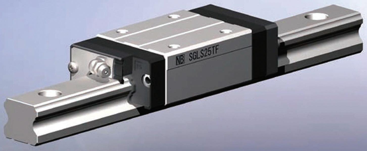

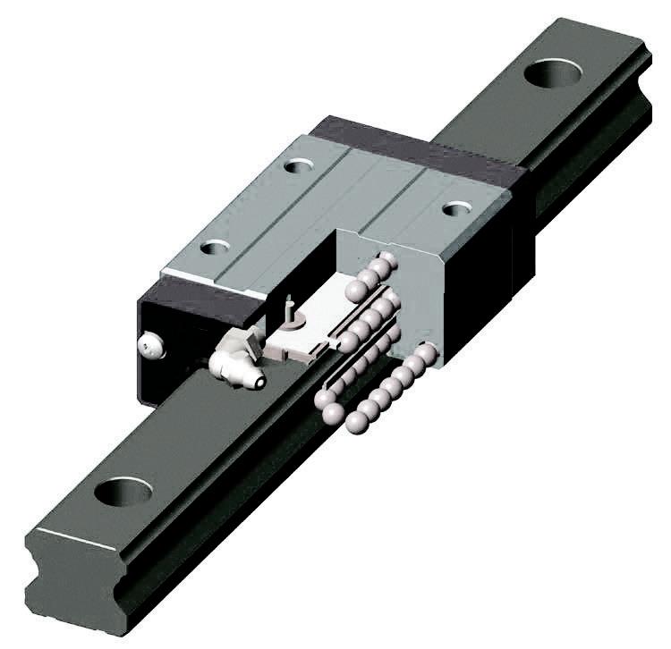


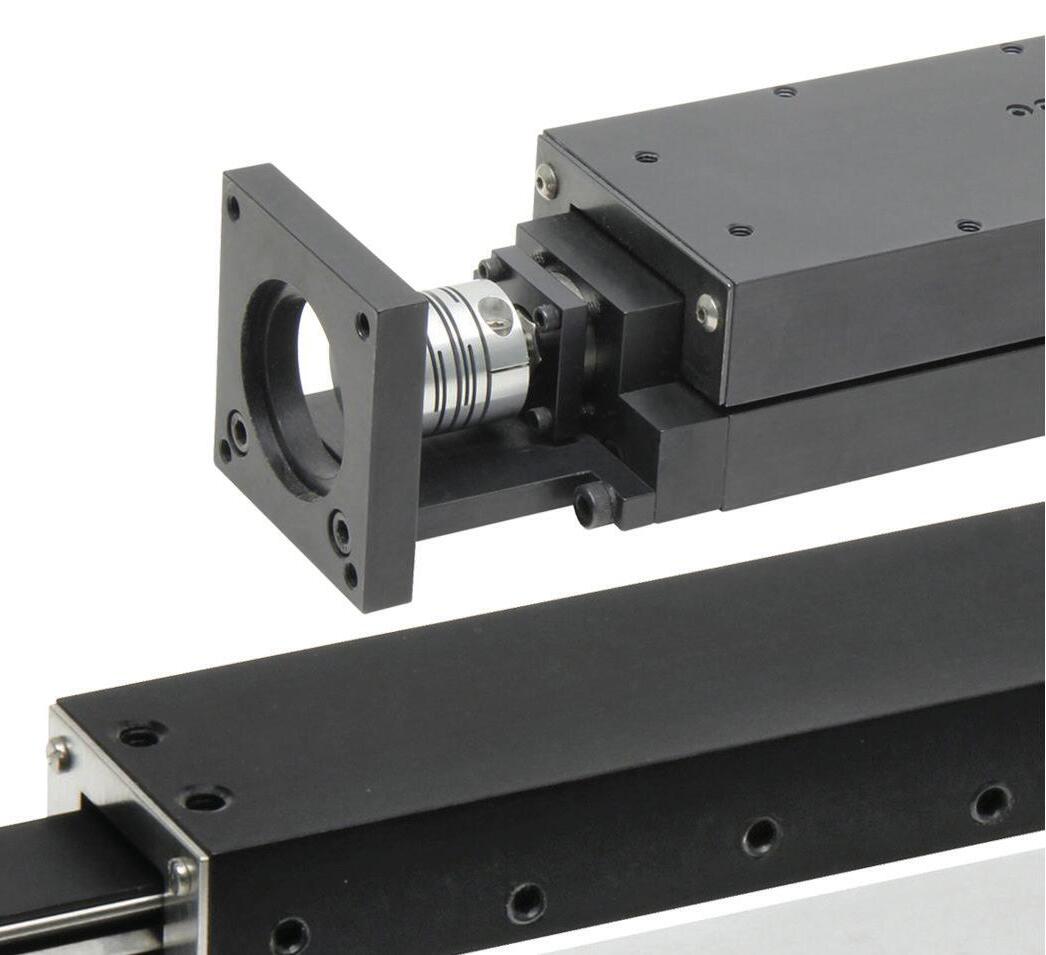
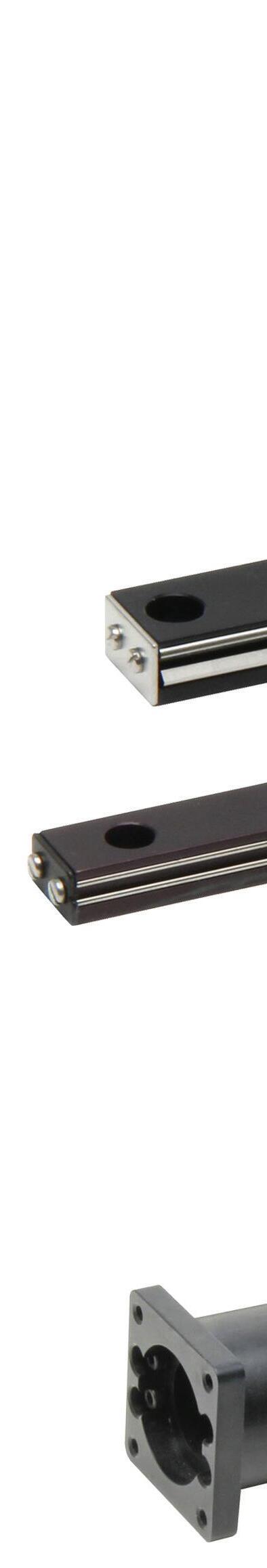
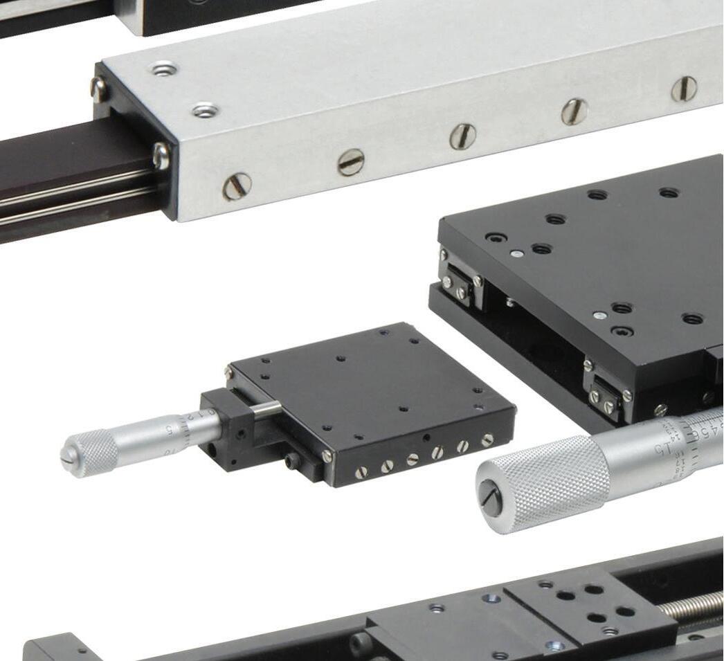
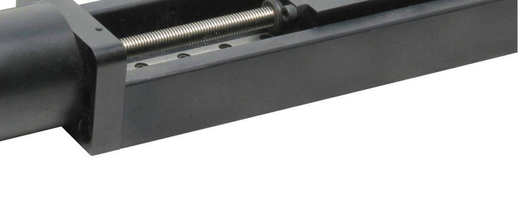
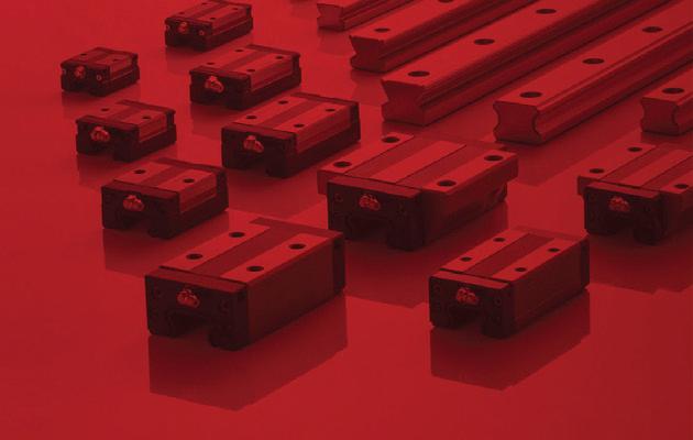
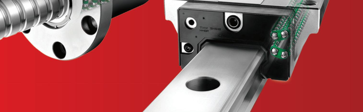
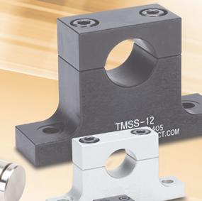
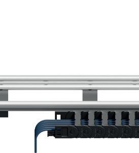
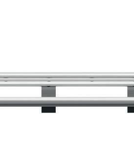
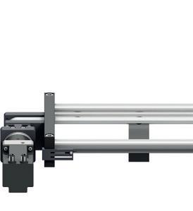
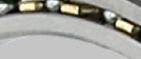
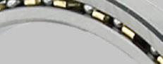
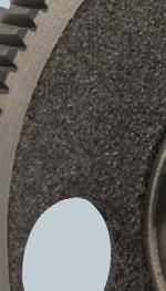
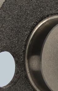
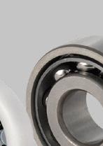
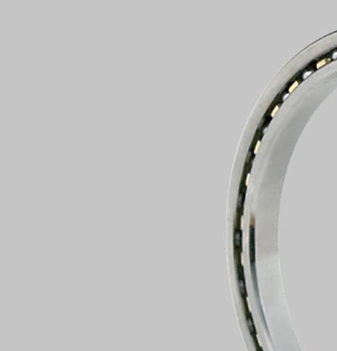
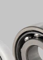
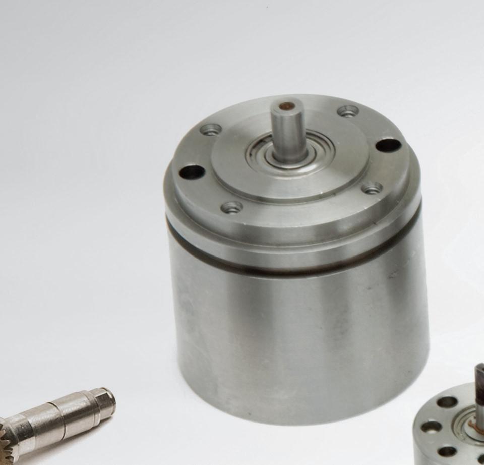
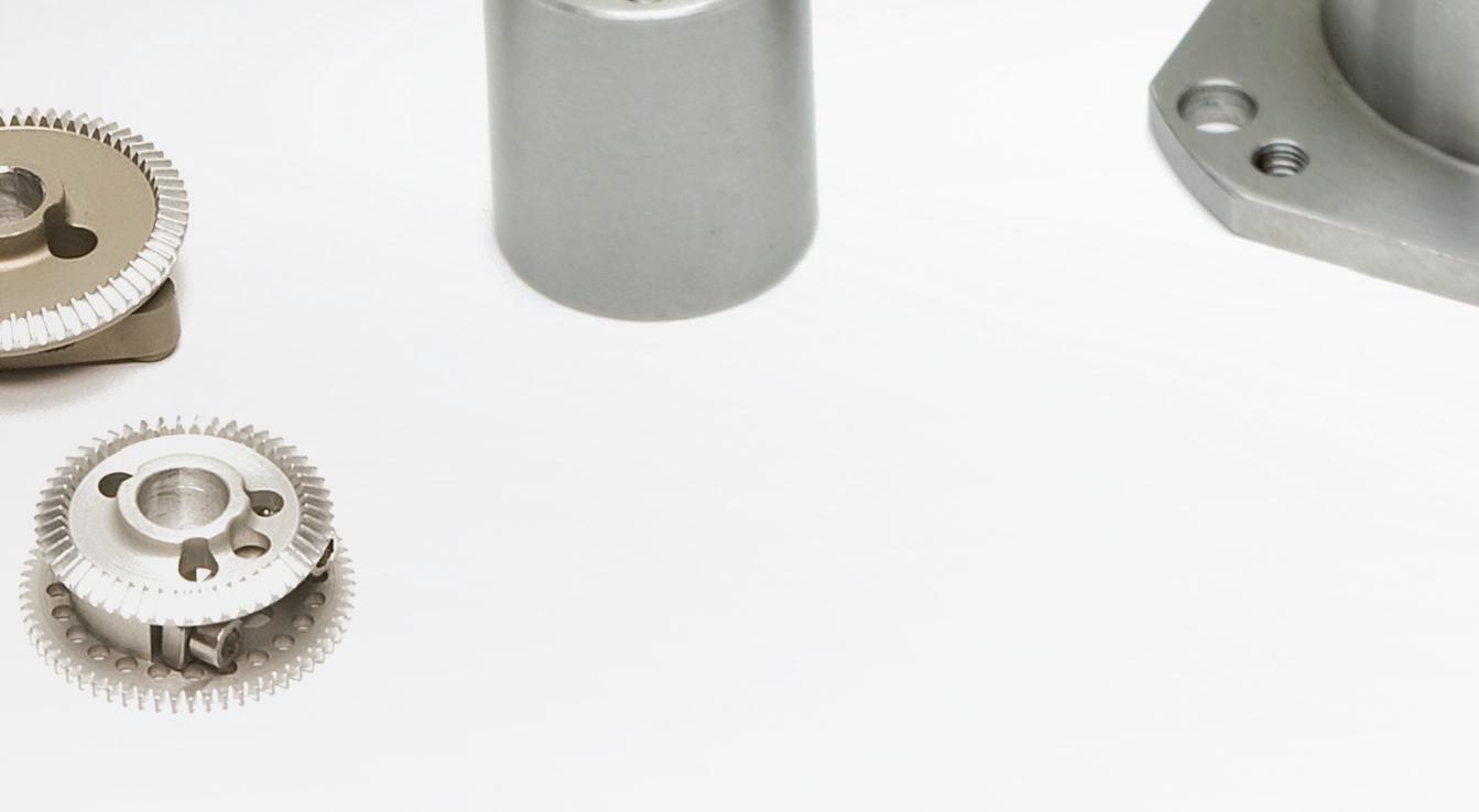
You have so many choices within each guide class –the NB standards, unique guides.
• 2 lubricant systems with lubricant options.
• Reverse Seal and Fiber Sheet Option provide maintenance free environments.


• Quick delivery from US inventory.
• Remarkable interchangeability.
• Myriad mix and match styles.
• 15mm to 69mm rail widths
• Extended block options.
• Choice of coating.
Precision ground raceways provide smoother ball movement. Four ball circuits for more load and accuracy. Fiber sheet lubricant delivery makes guides easier to maintain.* *Optional fiber sheet shown installed. Guide shown is from the SGL family within the NB Slide Guide product line.For the 2023 Design World Trends issue, dozens of industry experts shared their insights. Here is additional information from some of those experts on the design, manufacture, and distribution of consumer products.
Especially since COVID, the manufacture and distribution of home appliances, consumer electronics, and have evolved with advanced automation technologies.

Adoption of custom components in consumer products continues unabated.
Gallant: Our dc gearmotors can be found in many consumer products; the applications are essentially endless. Applications include handheld power tools, delivery robots, coffee machines, hunting devices, farming equipment, blenders, hand mixers, e-bikes, drones, and automated door locks. We never know what we will be working on next, which makes our work very fun.
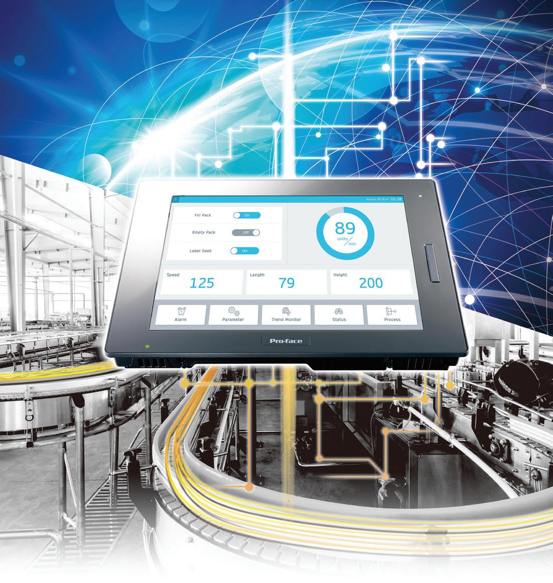
Solomon: Touchscreen penetration is on the rise among home-appliance OEMs. Until recently, OEMs shipped their highest-end models with touchscreens. Now though, intuitive and functional (and beautiful) touchscreens are being integrated into some more mainstream home-appliance models. The trend is towards reducing user-interface clutter and moving more controls to a single touchscreen.
Jung: Bishop-Wisecarver products impart long life to sliding doors, automated wine cellars, and other motorized designs needing smooth and quality operation.
Luchars: We’ve created custom electric motors having with 96% efficiency to power home appliances, power tools, and automated devices. In contrast with bulky off-the-shelf motors with copper windings, our technology uses a printed circuit board as the central motor component. A SaaS design platform lets innovators dial in precise performance and dimensional specs to create these custom electric motors that are lighter, quieter, faster, and requiring less raw materials to manufacture than traditional motors.
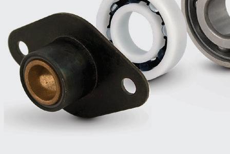
Maina: We welcome the opportunity to collaborate on new designs and updates to lower cost, extend life, and boost performance. Custom bearings and bearing assemblies can
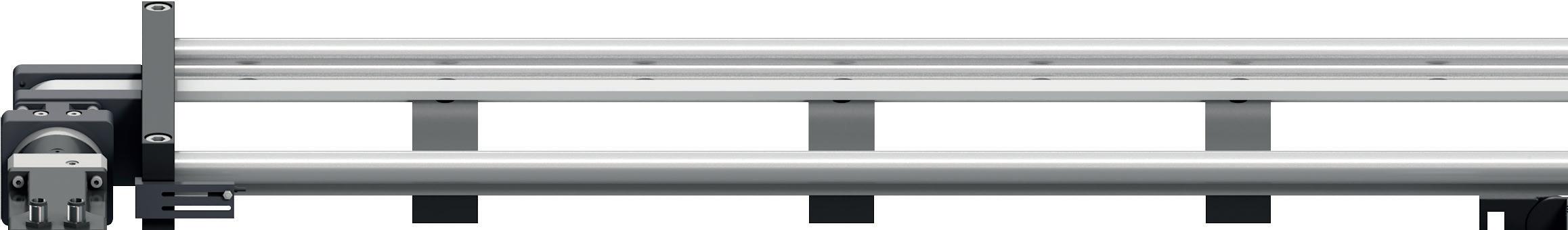
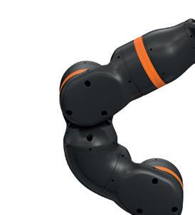
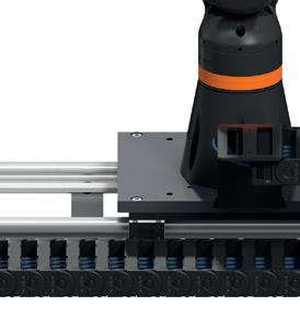
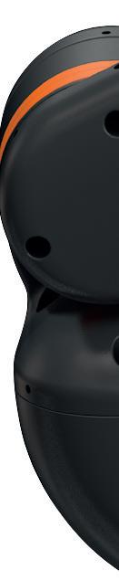
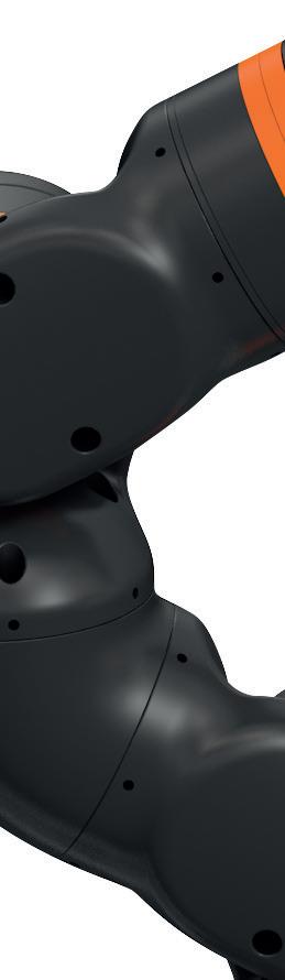
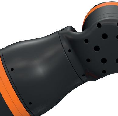
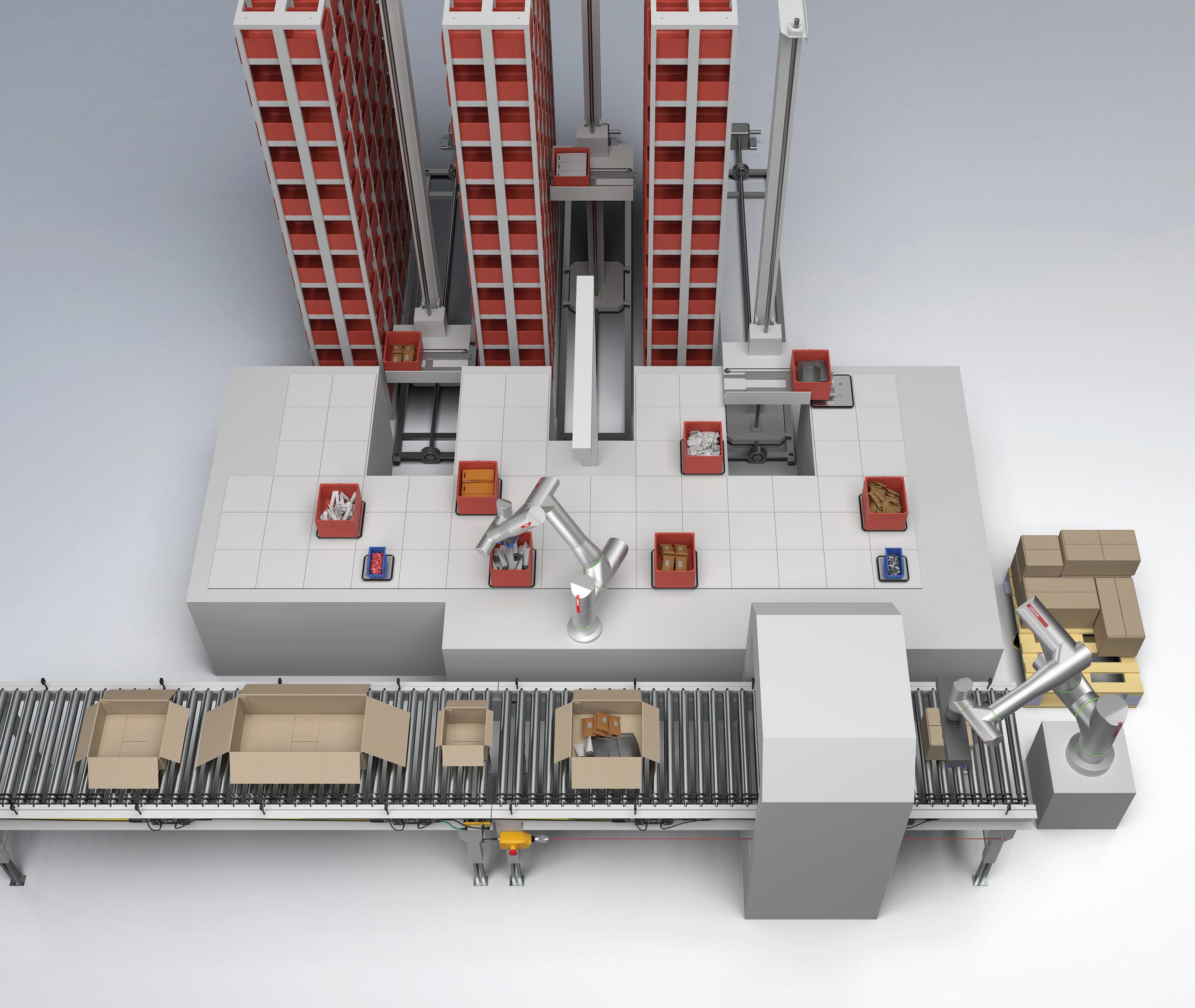
igus 6-DOF Robotic embedded-BDLC & electronics Link or ReBeL robots work as cobots and service robots in a wide variety of consumer-product processing

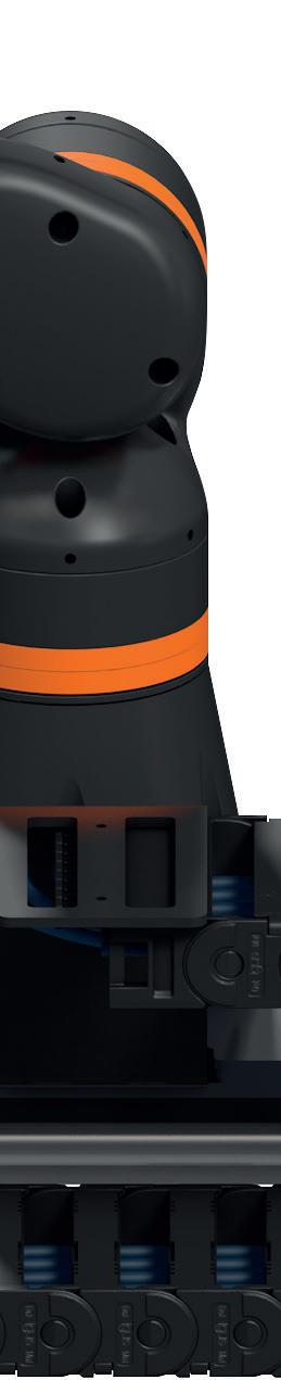
be designed (or redesigned) to solve specific application problems, lengthen service intervals, improve equipment performance, or save energy. In fact, about 25% of our total revenue comes from custom solutions.

Luchars: Recently we collaborated with Los Angeles film-equipment startup NODO on action-movie filming equipment. With us, NODO developed an Inertia Wheels MAX controller design leveraging PCB-stator motors. It offers haptics feedback with the electric motor deep in its wheel assembly for more torque sans cogging. We’ve also created unique designs for blenders and washing machines.
Maina: PBC Linear online product configurators let users configure linear-guidance and actuator products via prompted selections. Once configured, a budgetary list price is provided with the option to download 3D CAD models in various file formats. Design engineers can access several communication paths and connect with a team of application engineers dedicated to assisting and supporting design engineers. Often this via collaboration and (in some cases) videoconference application review.
Beasley: For power tools, we sell on features and benefits (not cost) so are primarily specified into professional-grade equipment

used by contractors and not do-it-yourselfers. Here, maxon’s compact power-dense BLDC drives make for lightweight, efficient, and precise designs for demanding applications. Recent trends in the power-tool market are shrinking operator skillsets requiring the ability to record operating times and conditions for future use. We address this need with closed-loop active-feedback smart drives as well as HMI connectivity.
Solomon: Safety regulations once presented a significant hurdle for appliance OEMs looking to simplify their interfaces because separate controls were needed with
functional safety certification for appliances such as ovens with self-cleaning functions and laundry machines with door-lock controls. Microchip is the first company to have removed those hurdles by allowing all controls — including functional safety critical buttons — to be moved to the touchscreen.
We offer the world’s only touchscreen controllers that are pre-certified for UL 60730
Class B (for U.S. shipments) and IEC 60730


Class B (for Europe, the Middle East and Africa or EMEA and Australia and New Zealand or ANZ shipments). maXTouch now lets OEMs develop single global models that can ship into Asia (where these standards are not mandatory but can be used as a point of differentiation for OEMs to position themselves as the safe choice for consumers) in addition to North America and EMEA.
New conveyor solutions are core to the manufacture, warehousing, and distribution of consumer goods. Warehouses around the world could number nearly 200,000 in just a few years. Where warehouse labor is in short supply, conveyorcentric automation often offers fast ROI to support and execute a wide array of materialhandling and packaging tasks.
Pardo: When you strip down almost any automation, the heart is conveyance. After all, the ability to accurately move products through each step of manufacturing and packaging depends on conveyance. That’s why selecting the right conveyor to complement a specific line’s automation requirements is so important.
We specialize in developing conveyance
for challenging automation applications. Often, product must be correctly oriented at specific times at various locations along the line. That’s not an easy thing to do, but our specialized conveyance solutions do this well.
Al Ramadan: As intelligent conveyance becomes common across industries, we could see increased use of linear synchronous motor-based systems. These motors provide a unique combination of precision, speed, power, and flexibility for advanced automation environments.
Fuqua: Data analytics and AI is being strongly considered for use in warehouse automation as well as life sciences. Add-on systems are already leveraging these technologies to drive conveyance predictive-maintenance programs.

Pardo: Dorner’s DCMove conveyors feature motors internally mounted in the tails to minimize the conveyor footprint and simplify integration. With flush-side design allows installation in tight spaces and maximizes belt coverage. In combination with V-guided belt tracking and precise rack-and-pinion belt tensioning, DCMove belt conveyors are suitable for logistics, e-commerce, and material handling.
Al Ramadan: Today’s high-speed conveyance now allows full dynamic control, data collection, and the ability to quickly change product specifications. Our ACTIVE Mover conveyor excels in case packing because it allows on-the-fly changes to case size; lets operators control pallets; and run packaging of various sizes based on demand.
Uzzolino: The need for conveyance will continue to grow with the proliferation of e-commerce, e-grocery operations, microfulfillment centers, urban warehousing, and warehouse automation in general. Brushless motor-driven rollers or MDRs eliminate belts and pulleys as well as motor-brush maintenance — and can have high IP ratings to operate in challenging environments.
In increased demand are power efficiency from low-voltage motors; integrated power management (to allow sleep mode when product isn’t flowing, for example); and highefficiency brushless motors. Also becoming mainstream are integrated networking and Industry 4.0 for IoT integration, cloud computing, analytics, functional safety, and artificial intelligence.
Soon (as power density and energy efficiencies continually improve) we’ll see directdrive motor-driven rollers without gearboxes … a solution needing almost no maintenance.
Al Ramadan: In the life sciences industry, Bosch Rexroth is seeing increased use of high-speed intelligent conveyance based on conveyors having independently driven pallets. Applications include the production of pharmaceuticals and medical devices. Intelligent conveyors are also heavily used in the consumer-packaged goods market. Here, the conveyors support case packing, cartoning, and flow wrapping.
Fuqua: The intelligent conveyance trend applies to warehouse automation as well. The goal is no longer moving something from point
A to point B. Increasingly functional conveyance solutions can now execute positioning, gapping, and accumulation tasks as well.
Increasingly important is the intersection of robots and conveyance in consumer-goods manufacture and packaging. Pardo: Robotic automation typically involves unscrambling, sorting, picking, labeling, case packing, sealing, palletizing, and stretch wrapping. Maximizing efficiency on these larger-scale lines requires conveyance that integrates well with robotic automation.
Al Ramadan: Our autonomous mobile robots support various applications and can even integrate with conveyors for pallettransfer applications. At a recent Pack Expo, we demonstrated a pick-and-place application using our ctrlX AUTOMATION platform, VarioFlow plus conveyor system, MP1000R autonomous mobile robot, and a Kassow seven-axis collaborative robot.
Pardo: We’re seeing many companies within a variety of industries take steps to automate warehousing operations because they see the long-term value that investment brings. Especially in the e-commerce segment involving products and parcels continually on the move, the best way to maintain those shipping goals is through robotic automation. Of course, a critical component to ensuring those products are sorted, picked, labeled, and shipped ontime is conveyance.
As more industries add automation to their warehousing, conveyance will be vital to
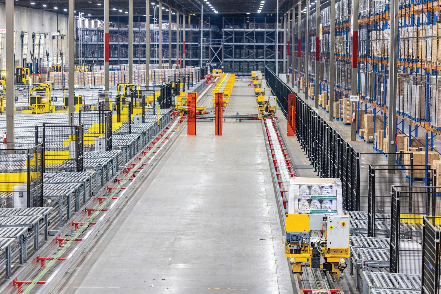
Henkel’s Kentucky logistics operations integrates Industry 4.0 innovations to enhance efficiency, optimize storage space, and drive digital automation (DX) insights that help improve decision-making across the company’s supply chain.
The facility supports the production, storage, and distribution of Purex, Snuggle, Persil, Schwarzkopf, and Dial-brand products with DX capabilities to proactively respond to dynamic market conditions. The 1.4 million ft2 logistics hub can store up to 200,000 pallets and supply up to 1,000 trucks per day. (Image courtesy of Henkel)
maximizing efficiency. We lead in developing new technologies to aid in e-commerce, automation, material handling, and packaging. Here, robots do much of the heavy lifting … but conveyors are the heart of the automation.
Varley: Our robotics are increasingly used for the production of home appliances, power tools, and consumer electronics.
Our DCMove belt conveyors are well paired with collaborative robots. Cobots are becoming more universally accepted; they’re safer for employees to work around and are
Brad
James
Chad
Andrew Jung | Director of engineering Bishop-Wisecarver
Marco
|
Jeff Maina | Senior applications engineer PBC Linear
John Uzzolino | Business develop manager Parvalux
Robert
|
|
easy to setup. Of course, robotic automation is not a one-size-fits-all solution. Quickly gaining popularity are small agile cobots designed to safely share a workspace with people. This is opening new applications within packaging, assembly, and other industries that previously involved no robotic interaction.
For example, robotics are increasingly common for modest operations in end-of-line applications where light parts are palletized. Here, robots can relieve employees of monotonous pallet loading and unloading all day long. That save organizations money in the long run while reducing the risk of repetitivestress injuries.
Pardo: Robotics manufacturers have gone to great lengths to remove the guesswork and fear associated with programming and make integration with conveyance an easier endeavor. So many traditional conveyor facilities are now considering adding robotics.
Streamlining conveyor-and-cobot integration begins with robotic manufacturers who’ve created their own software to make installation and programming fast and easy.

Universal Robots offers a software package that allows Dorner to piggyback off their system. For example, Dorner’s 2200 Series conveyor and related accessories can be controlled with Universal Robot’s software plugin to aid in setup, configuration, and control. Once the program is installed, conveyors can be added to the cobot control program, and users can set inputs and outputs needed for starting, stopping, speed reference, and monitoring status information. This integration acts as a handshake between the conveyor and cobot so operators can run multiple conveyors off one controller as well as observe overall line performance.
Fuqua: Traceability and inspection are key in logistics — and that includes usage of barcodes, tracking product locations within a warehouse, and 3D scanning of package sizes. Here we’ve seen some big advances. For serializations and tracking of barcodes, our ctrlX AUTOMATION platform can automate that tracking. In addition, warehouse engineers can use the platform as an IT device when monitoring entire operations.
Read the rest of our experts’ insights in this series by visiting designworldonline.com/trends.


Actuators are central to many industrial applications. A range of actuator types exist to accommodate the wide array of application uses such as electric actuators including linear motors, pneumatic and hydraulic actuation, ball- and lead-screw actuators, as well as belt and chain types.
No matter the type, one of the most important parameters when sizing and selecting an actuator for an application is the actuation speed. However, like many terms used in the linear motion industry, such as “heavy duty,” “miniature,” and “corrosion-resistant,” to name a few, there is no industry standard that specifies what constitutes a “high-speed” linear actuator.
Nevertheless, there are some general guidelines that manufacturers follow when classifying and marketing their actuators as high speed. These guidelines are typically based on the drive mechanism, actuator type, and even primary use or industry. Understanding these distinctions can help you make an informed decision when your application calls for a highspeed linear actuator.
The limiting factor of a linear actuator’s speed capability is typically the drive mechanism.
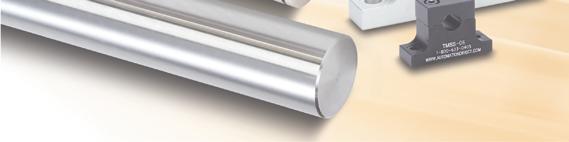
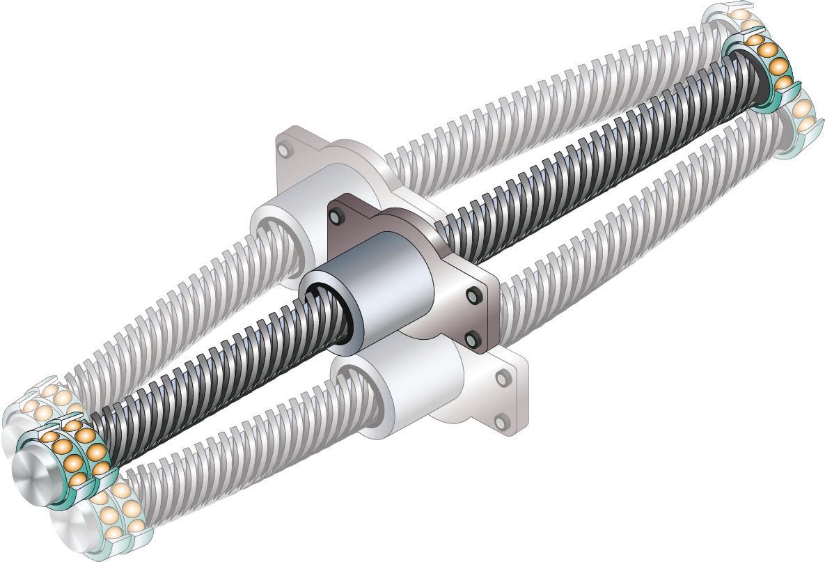
Ball screws and lead screws are limited in speed by their tendency to whip, which is a function of the screw diameter, length, and end bearing arrangement.
Because lead screw designs are based on sliding contact and generate high heat due to friction, they often have lower maximum speeds than ball screws of a similar size. Of the screw technologies, actuators based on ball screw drives are more likely to be deemed “high speed” than those based on lead screw drives.
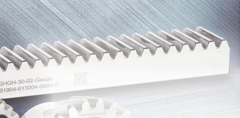
Actuators based on belt drives or rack and pinion assemblies are typically able to reach higher speeds than ball screws, provided they are properly tensioned (for belt drive
versions) or preloaded (for rack and pinion versions). Actuators with steel reinforced belts can achieve speeds of 10 m/sec or higher, while rack and pinion driven actuators can commonly reach speeds of 5 m/sec.
Another factor comes into play when discussing high speed linear actuators; the type of actuator. The “high speed” designation is most often applied to thrust-rod type actuators (also called electric cylinders) because their primary applications involve pushing-pulling and inserting operations, which typically require short extension and retraction times. These actuators can be either ball screw or lead screw driven, with speeds ranging from 0.1 m/sec to more than 1 m/sec.
A few manufacturers even offer beltdriven rod-style actuators that can reach speeds to 2.5 m/sec.
Slider or carriage-type actuators (also called rodless actuators) can achieve even higher speeds than rod-type actuators in many cases. But because their primary uses are for positioning and transport, typically with high loads, they are less often marketed as high
speed. Rodless or slider-type actuators have a wide range of drive options, including lead screw, ball screw, rack and pinion, belt, and linear motor.
Linear motors inherently provide the highest speed capabilities, with no mechanical parts to limit speed or create friction and heat. But when incorporated into a linear actuator, linear motor drives are limited by the speed of the guide mechanism. Similarly, steel reinforced belt drives can achieve speeds greater than 12 m/sec, but like linear motors, are limited by the maximum speed of the guide. The most common guide systems used with linear motors and belt drives are recirculating profiled rail bearings, whose maximum speeds typically reach up to 5 m/sec., limiting the overall speed of the actuator to 5 m/sec or less.
However, higher speeds can be achieved when belt drives are paired with cam roller guides instead of recirculating profiled rail bearings. With preloaded cam roller guides and a properly tensioned, steel-reinforced belt drive, these high speed linear actuators win the race, with travel speeds up to 10 m/sec.
The case of micro- and nano-positioning
For micro and nano-positioning applications, the actuators of choice are often based on voice coil or piezo technologies. Ultrasonic piezo actuators can reach speeds of 0.5 m/sec or greater, but they typically have maximum strokes of 100 mm or less. Voice-coil actuators operate at speeds to 2 to 3 m/sec with strokes that are typically to 150 mm, although some variations haves strokes to beyond 250 mm.
While these specifications may not fit the general definition of high-speed linear actuators, considering the rapid acceleration that is required to reach these speeds in short stroke lengths, piezo and voice coil designs can easily be classified as “high acceleration” actuators.
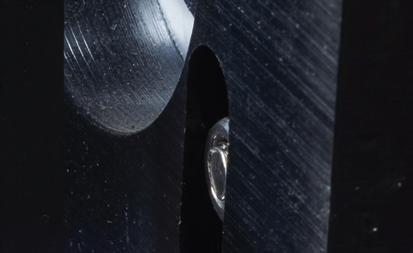
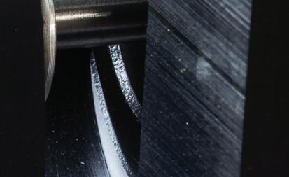
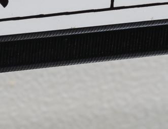
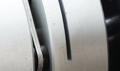
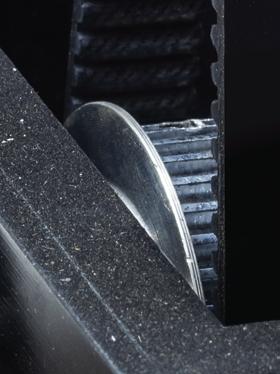
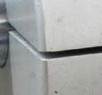
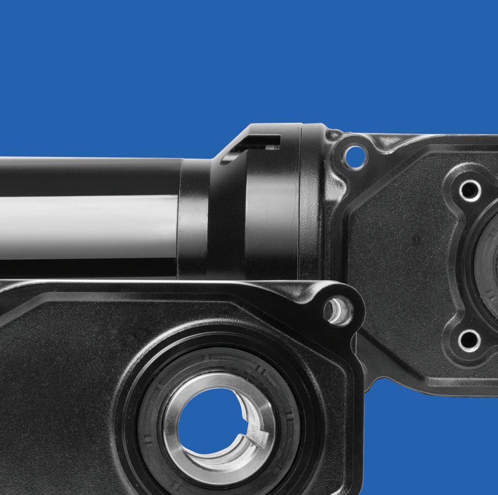
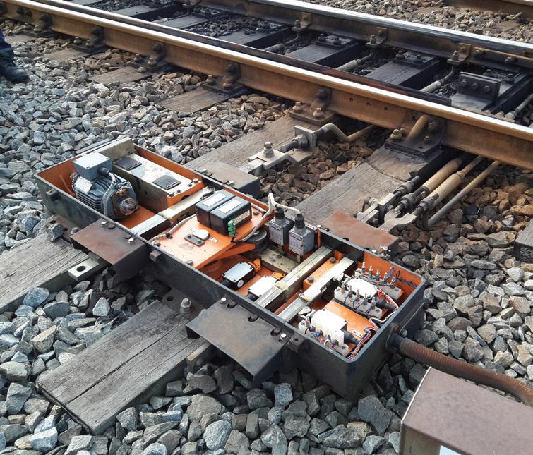
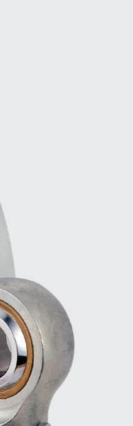
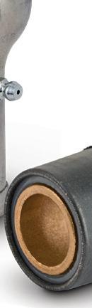
Actom Signalling, a Southern African railway signal-equipment company, has found minimal wear in accelerated wear testing on Vesconite slides in its point machines. These machines control railway tracks and switch the tracks to which particular trains will be directed.
Actom engineering projects and contracts development technician Wayne Meyer confirms the test results.
Testing was executed over a few days in late 2022 on a randomly selected B1 Switchmatic Point Machine that was taken out of operation for the express purpose of testing the point machine’s performance.
“We must back our products so periodically we do these tests,” says Meyer.
“They provide comfort to our customers on the performance of our machines.”
The tests put the machine through its expected operating life.
More than 5,000 actuations (movements of the point machine drive bar) were tested at the company’s factory in Germiston, South Africa. Included in the testing were Vesconite slides located around the detection, lock, and drive bars where they exit the machine housing.
The point system blades and bars also run on Vesconite track, so are enclosed within Vesconite when they are within the point
system housing. Meyer notes that most of the wear — around 0.17 mm — was on the bottom Vesconite slides. “This is very little for the amount of work that was done,” he says.
Wear on the topmost and side liners was almost undetectable, with wear of 0.05 mm being present. Point machines are critical in controlling the directional change of a train and for the safety of rail services.
Among the important components of the point machine are the detection blades, which determine the position of the right and left lines on the track; the locking blades, which physically locks the rail in place in a new position; and the drive slide, which is used to push the tracks into the correct position.
“Each actuation of the B1 Switchmatic point machine involves a 300-mm stroke, so there’s 300 mm of movement over the Vesconite liner each time the machine actuates,” says Meyer. “For the amount of wear, that’s very good.”
The B1 Switchmatic is Actom’s most popular point system and is a well-tested machine that was first developed in the 1980s. It’s the model on which Actom’s other point systems are based.
Actom has also developed the C1-H clamp lock point machine, the in-sleeper or integrated point machine, and the yard point machine — all of which include Actom’s important safety features and locking mechanism.
The C1-H is a smaller machine that was
developed in the 2000s and is frequently used on passenger rails on which the rail tracks are normally located closer to one another than would be the case with freight rail.
A yard point machine is a robust, portable machine which is used in shunting yards and operated with high frequency.
The in-sleeper machine is Actom’s newest machine to combat vandalism and theft by being small enough to be installed securely between the rails and inside the concrete sleepers.
All these machines make extensive use of Vesconite; some 40 and 50-year-old machines still operating feature low-friction wear-resistant Vesconite that hasn’t failed yet. For more information, visit vesconite.com.
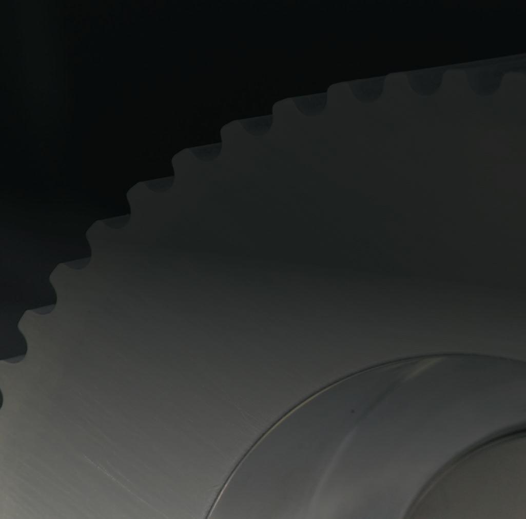
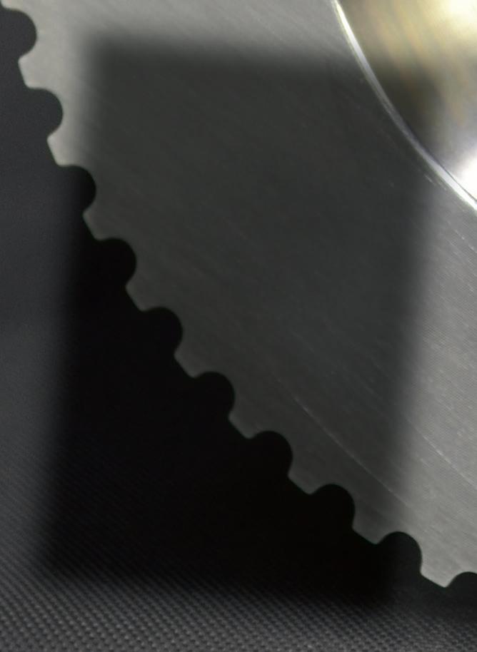
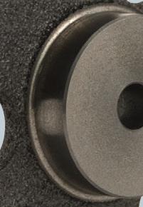
Synchronous belt drives dominate motion control designs for positioning and other precision functions. Here we detail V belts and other belt types used in industrial, robotic, and consumer designs for both linear and rotary axes.

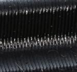
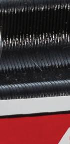
V belt drives — such as this small V belt drive on a motordriven axis inside a consumer-grade washing machine — are ubiquitous in motor-powered applications. They pair belts having a chamfered (typically trapezoidal) profile with pulleys that are circumferentially grooved to match. A key benefit of this geometry is the way in which the belt wedges into the pulley groove with increased tension for a corresponding increase in beltand-pulley surface friction. That in turns minimizes slippage and boosts allowable torque transmission. Image: Dreamstime


Modern flat belts are either endless (welded or otherwise closed into a hoop by the manufacturer) or open. Common on grinders, fans, grocery conveyors, and other power-transmission applications, drives based on flat belts rely on precisely set tension for maintaining the proper the friction coefficient between belt and drive pulley.
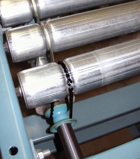

Even today, many flat belts are made of natural materials as well as synthetic yarns featuring various filament structures. Flat belts made of polyurethane are common on the ends of conveyors consisting of roller arrays — to gang powered rollers (integrating a motor in its cylindrical body) to passive nonpowered rollers. Flat belts with polyester tension members excel where high tension (but little stretch) is required; coatings of PVC, polyurethane, and rubber enable high friction for use on high-speed axes running to 22,000 feet per minute.
One specialty type of flat belt indispensable in settings subject to high temperatures and corrosive washdown (or other chemicals) is that made of thin stainless steel. These flat belts are precision welded closed to traverse just a few centimeters to dozens of meters — and often perforated to accept the positive engagement of studded pulleys. Flat metal belts also exhibit no stretch or creep, so allow precision positioning of workpieces … and can protect workpieces sensitive to electrostatic charges with grounding.
Round belts (sometimes called O-ring belts or O belts) have a circular cross section; they’re common on axes of consumer-grade electronics with moving elements, office-grade printers and scanners, and light industrial equipment such as tabletop robotics with modest to moderate power-transmission requirements. Most round belts are extruded from neoprene, propylene, or

cross-linked urethane (either reground or virgin) and then butt welded together into endless loops. Their elasticity makes them more forgiving of suboptimal installations, but at a sacrifice of power capability. Mating pulleys have semicircular grooves and diameters no less than sixfold the belt’s cross section. Texturized O-belts have lower coefficients of friction but are better able to resist abrasion and overheating.
The caveat with these belt types (and really any belts not employing positive engagement via teeth) is that they can exhibit slip and creep.
Creep is a cyclical elongation of belt (with some measure of elasticity) as it travels around the loaded side to the slack side of its circuit … and is considered normal. Proper tension holds the dimensional changes of creep to within 0.5% of the belt’s normal length and cross section. There is a cyclical stressing associated with creep as well as the flexing of belt around its pulleys — which does ultimately limit belt life but doesn’t induce dramatic temperature increases.
In contrast, belt slip due to improper tension or (worse yet) improper design can quickly generate heat buildup. Simple measurements taken of belt temperature along with geometry, vibrations, and sound generated (including squealing upon startup) can accurately indicate the amount of tensioning or retensioning required. Belts transmitting high power require greater tensioning or risk slip
and other modes of improper operation.
Design tensions are often defined by the ratio of belt drive-side tension divided by that of the slack side — along with a constant wedging design factor (for V belts) and the belt-to-pulley dynamic friction coefficient. Design tension ratios for V belts tend to be higher than those for flat belts.
A V belt’s primary subsection is its tension-bearing top. This top includes fiber cords for strength to pull actual traction load. Modern tension-member cords are often aramid, polyester, fiberglass, or steel ... and pre-stretched variations help minimize stretch. The cords embed into the main belt material that serves to hold the belt body together and shed heat. The working side of V belts (which engages the pulley) is a compression section designed to wedge into pulley grooves for reliable shock-damping engagement. In many instances, a rubberized fabric cover ruggedizes the belt surface and prevents slipping (which in turn prevents overheating tension cords).
One additional note here: Though V-belt slip is usually detrimental, it can be a helpful behavior on axes that are truly jammed — serving to protect more expensive components in the drivetrain.
Though versatile and forgiving, frictionbased belt drives that are improperly sized can slip tangentially on the pulley — a form of lost motion — and axially creep. Both of these issues can in turn cause unreliable speed
output. Just remember if a V-belt drive makes the most sense for a motion axis: Output torque depends on belt resistance to tension and beltpulley adherence. The latter is why oils and greases must be kept away from belt drives … or else failure due to slipping may arise.
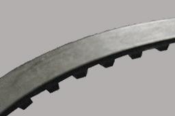
Not to be confused with toothed (synchronous) belts for motion-control applications are cogged V belts. These have notches on the working a.k.a. pulley-contacting belt surface to:
• Allow airflow for cooler operation
• Boost flexibility — to travel around pulleys having diameters smaller than otherwise allowable
These notched V belts are available in a wide array of classic and narrow configurations. In addition, they often have a raw-edge design (sans cover) for more space in the belt cross section for load-carrying cord. Any standard V belt that is cogged will have a name with an X suffix — such as BX or 3VX, for example.
Though most associated with heavy powertransmission applications, V belts do in fact find use in precision motion designs as well. Embrace the oxymoron: Static motion designs — those that only depend on consistent end-ofmove positioning — can tolerate the errors of friction-belt drives. In contrast, dynamic motion designs require axes that move predictably over their complete strokes — even if load varies during operation. Here, engineers typically specify low-backlash toothed belts needing shallow clearance for pulley engagement. Single V belts for these motion applications often take the form of light-duty or fractional horsepower V belts denoted by 2L, 3L, 4L, or 5L codes with the latter dimensionally resembling so-called classical A and B-coded V belts.
V-belt specification generally references crosssection geometries including the belt’s width at its widest, V angle, depth of engagement, height, and overall pitch length. The latter geometry is the circumferential length along a belt’s pitch line. Final V-belt specification is then determined by which correctly dimensioned belts have sufficient power ratings (defined by rpm and sheave speed) to satisfy the application’s nominal


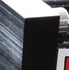
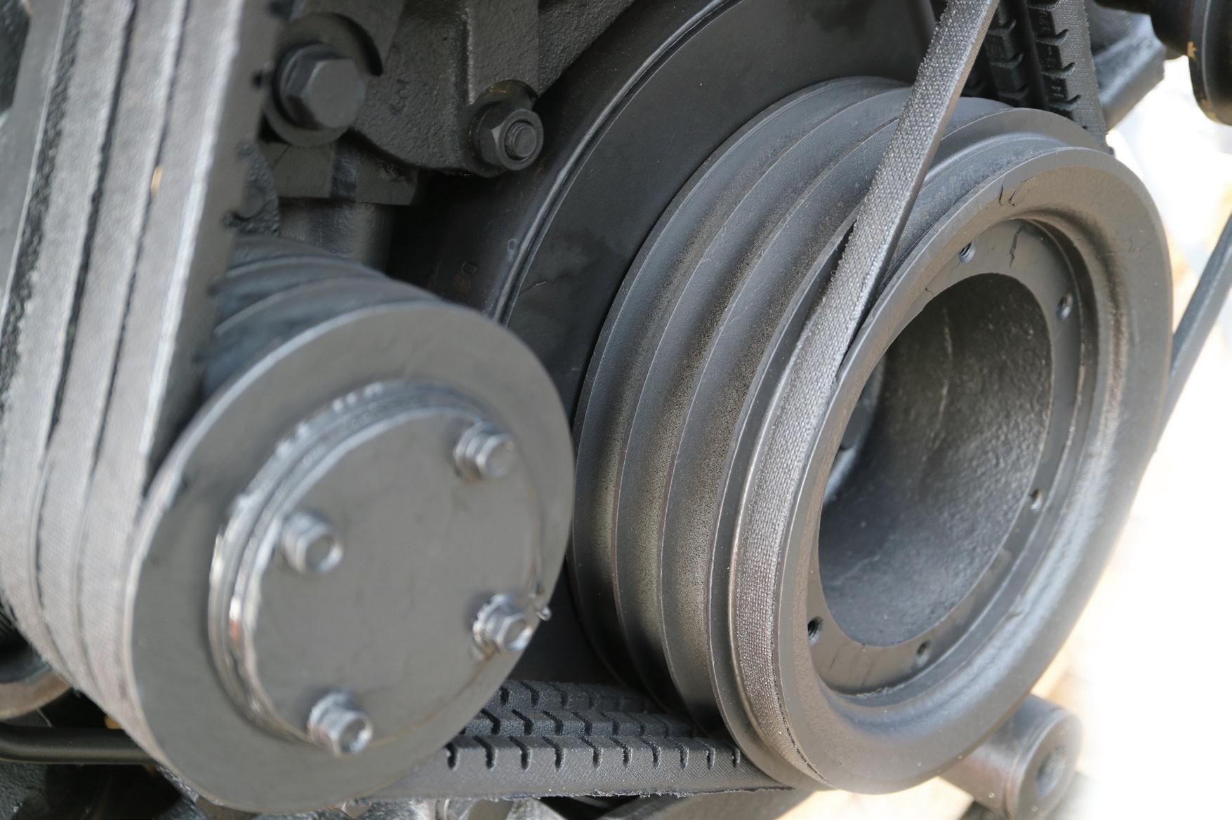
Belt drives are indispensable in appliance applications that need to be reasonably quiet.
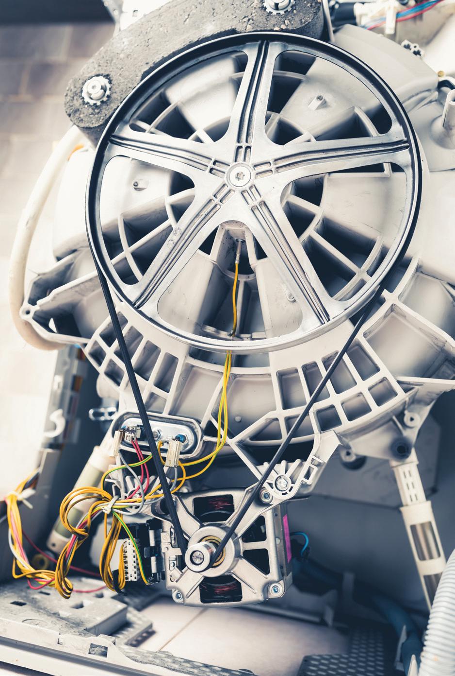
Image: Dreamstine • Nikkytok
horsepower (at the driving motor’s output shaft) and the applicable service factor.
To simplify V-belt specification, suppliers have come to publish (and include in design software) information about various V-belt service factors that accommodate various applications’ typical demands … as well as losses from variable speeds and loads as well as detrimental environmental conditions such as shock, vibration, and heat.
V belts with so-called classical geometries just mentioned are a rugged if moderateefficiency option. In the U.S., standardized geometries are coded A and B (most common) as well as lesser-used C, D, and E having progressively larger cross sections. Narrow V belts are named with progressively higher numbers for progressively larger belts — and have V suffixes. Double-sided V belts are those with a double-angle or so-called hexagonal geometry for winding through and driving serpentine drive arrangements; these are coded AA, BB, CC, and so on. These codes are listed in specification software and manufacturer catalogs as well as printed on the belts themselves … usually followed by a dash and then a number denoting the total working length of the belt in inches. Even International Organization for Standardization standards such as ISO 8419 (dictating the standards for narrow V belts) lists values in millimeters that reflect these standards first established in Imperial units.
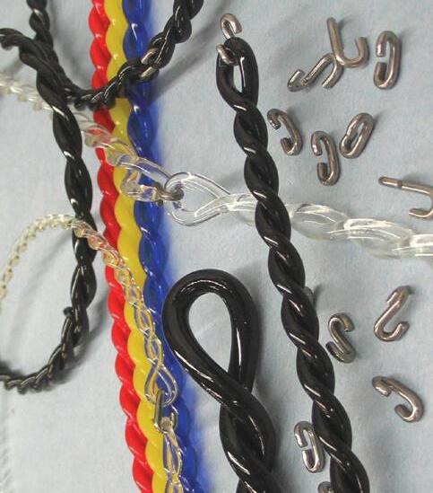
Of course, the latter (length) code does not appear on adjustable V belts — those made of a series of interlocking sections joined by tabs or other fasteners like industrial chain. These linked belts (suitable for even high-power and high-speed axes to many thousands of rpm) are sold in open sections that are cut to length and then closed by the installer in the field.
Another V-belt design is that of joined V belts. Unlike ribbed V belts (covered in other Design World articles) that have a common foundation of thickness sufficient to feature reinforcement throughout, joined V belts have discrete trapezoidal sections. These sections are themselves reinforced but joined by just a thin layer of tension material. Such joined V-belts are easier to specify than matched sets and far less problematic than separate arrays of V belts running in parallel — especially on axes subject to intermittent forces and speeds. That’s especially true on axes that might otherwise require a dozen or more V belts in parallel for sufficient power transmission.
Axes run off 2-hp or smaller motors under the control of variable speed drives (never prompting more than fivefold speed increases) accept V belts having 4L, 5L, A, or B notations. Axes with more dramatic speed variations necessitate other V belt that’s also standardized and coded — in this case, with four-digit values and a V (for narrow) suffix.
Standards established by the Rubber Manufacturers Association (RMA) and the Mechanical Power Transmission Association
(MPTA) inform specification approaches that first satisfy design horsepower requirements. Using this approach, a service factor applied to nominal (rated) motor or axis horsepower (to accommodate friction, vibration, heat, and other losses) ensures reliable and efficient belt-drive operation. These service factors are published for machine and drive types typical to various industries.
Power ratings are well documented for all standard V belt and pulley sizes and speeds. But arc and length correction factors (along with the belt-installation center distance and speed ratio covered in a moment) affect this basic power rating. Center distance is often presumed for set pulley combinations. That said, long pulleyto-pulley center distances yield high power ratings and shorter yield lower ratings.
Next, the driven-to-drive pulley speed ratio (based on any difference in their diameters) is calculated to yield output belt speed (sometimes called rim speed). High speed ratios magnify the effect of center distance changes on drive power ratings. Then the maximum output rpm or fpm (based on the axis geometry, pulley construction, and level of balancing) is calculated — with multiplane dynamic balancing increasing this value. Finally, work output for a given time (based on horsepower x 1.341) yields a value expressed in kilowatts.
One last design consideration for machines employing V belts is the level of balancing required. Refer to Balancing the pulleys of belt drives on linearmotiontips.com for more on this topic.
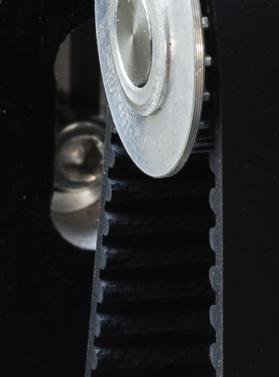
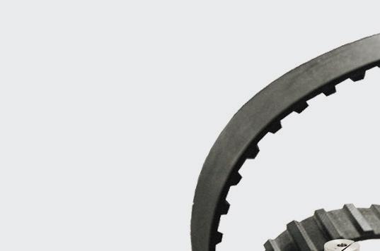
Not to be confused with toothed (synchronous) belts for motion-control applications are cogged V belts. These have notches on the working pulley-contacting belt surface.
Timing Belts & Pulleys


Couplings


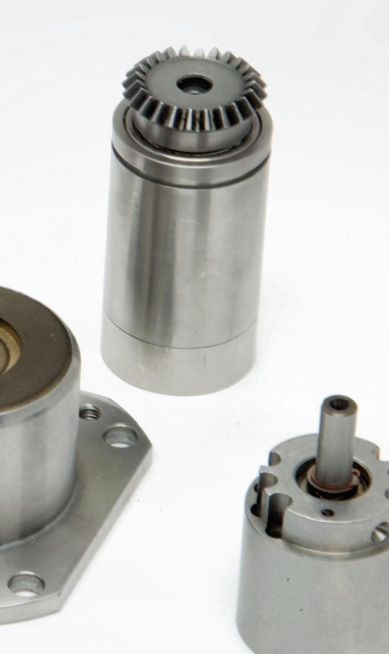
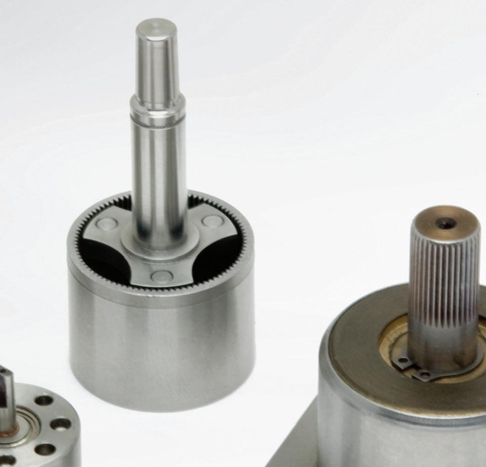
Miniature Gearheads
Planetary Gearheads


Bearings & Linear Motion Products


Brushless DC Motors


Integrated Motor Drive Controllers
Frameless Motors


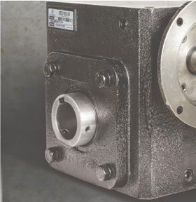
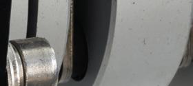
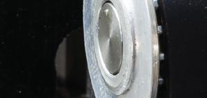
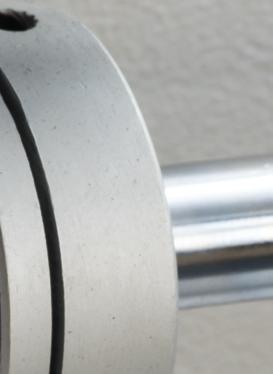
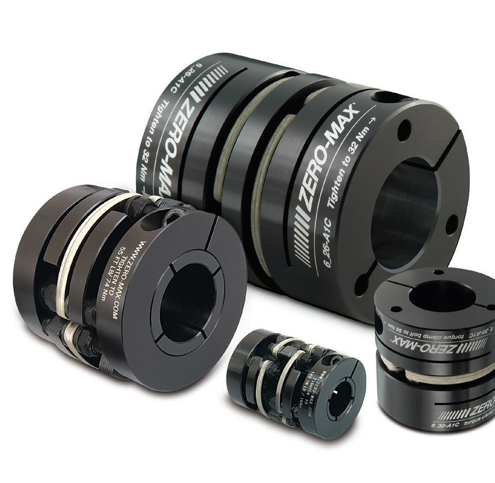
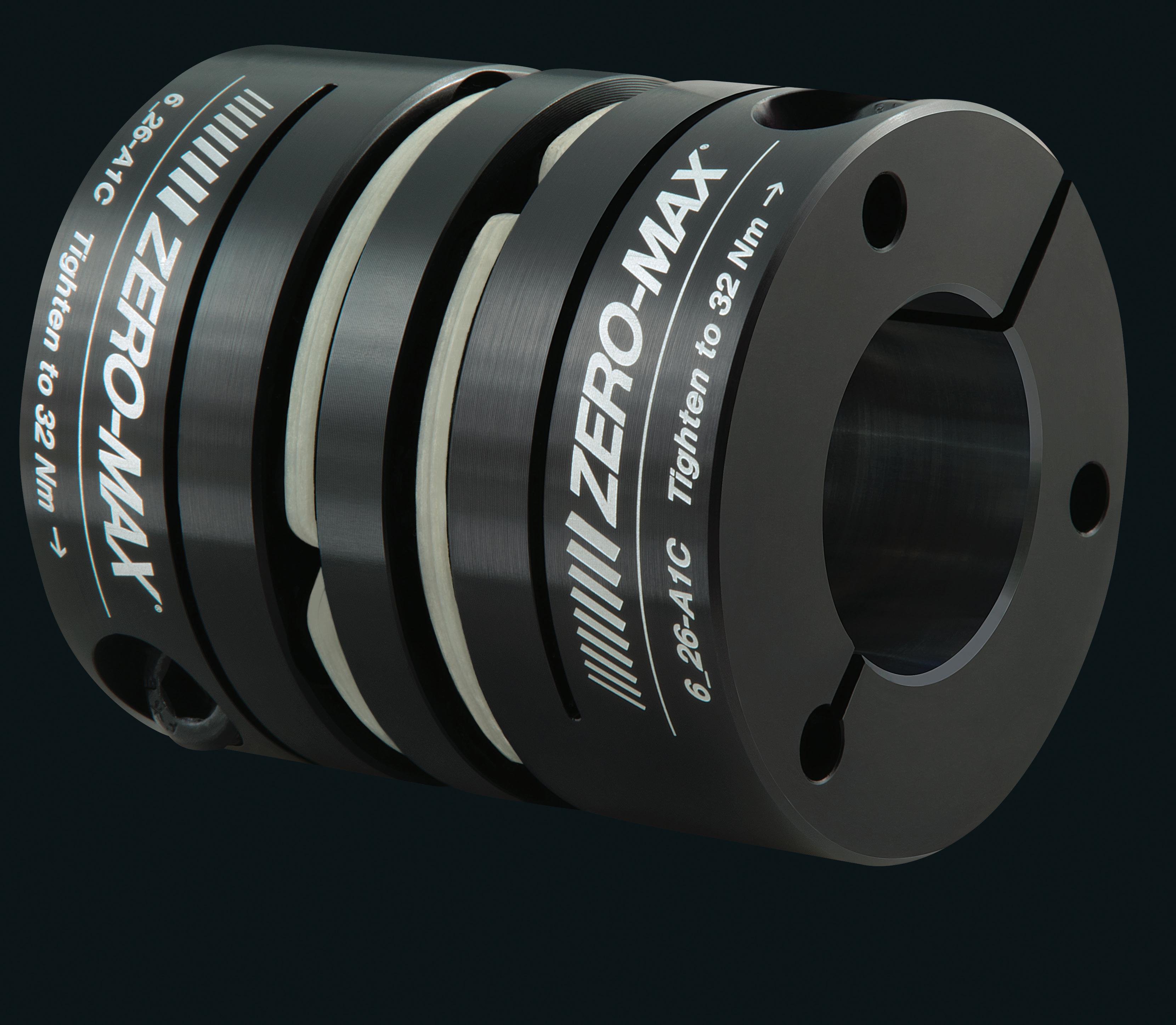
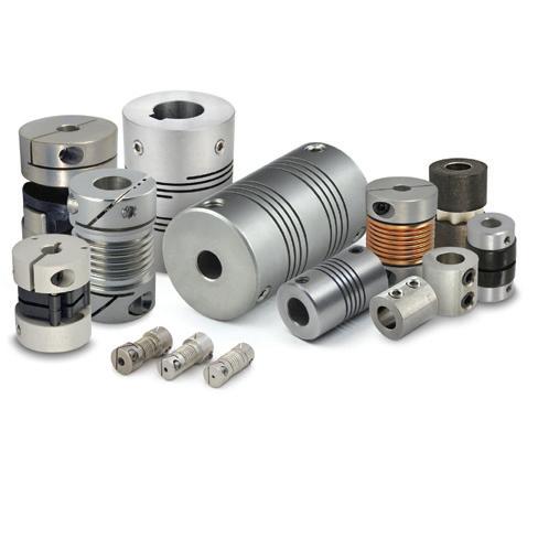
Couplings connect rotating shafts in equipment powered by electric motors and other drive mechanisms and transmit torque and angular velocity. Flexible variations compensate for misalignment and many of the latter even address vibration and improve system dynamics.
Design considerations include machine or installation construction and backlash, torsional stiffness, damping, inertia, torque ratings, maximum rpm, size, misalignments, ease of installation, robustness, and cost. For power transmission (as in motors for pumps and large materialhandling setups) common choices are gear, disc, elastomeric tire, grid, jaw, and Oldham couplings because of their
ruggedness and ability to transmit very large torques. Motion-control applications (as for axes employed in precise positioning of loads, for example) typically employ couplings capable of often more modest but far more precise torque transmission. These include curved-jaw, beam (slit), bellows, disc, and other zero-backlash couplings.
Any misalignment that couplings accommodate should be what’s otherwise unavoidable even after proper machineaxis squaring and installation adjustments. That’s because misalignment — manifest as parallel, axial, and angular misalignment— degrades efficiency, induces bearing wear, and excites machine natural frequencies. To review, the maximum amount of angular misalignment for which a coupling can compensate is expressed in degrees; parallel misalignment between the shafts a coupling connects is expressed in inches or millimeters. Axial misalignment is also a length value; it’s the maximum permissible spread between coupled shafts — and in fact, a misalignment permutation often most affected by thermal effects. Flexible couplings for motion control are often less forgiving of misalignment than those for more straightforward power transmission, and resolve it with specialty design features.
A related phenomenon and a coupling consideration specific to motion-control installations is backlash. In applications for strict power transmission, backlash is far less of a concern than that of efficient torque transmission — and actually a characteristic that (in normal moderate quantities) helps make some couplings in these settings more efficient and forgiving of misalignment. In contrast, couplings on the outputs of steppers and servomotors are designed to prevent the lost motion that can degrade output-product quality or overall machine throughput.
Note that there is a difference between backlash (which is true mechanical clearance) and the torsional deflection or windup that all loaded rotary components exhibit. Most couplings for motion applications are inherently backlash free or preloaded to eliminate backlash — but they all have different torsional stiffnesses, which is sometimes a tradeoff for lateral flexibility.
Design engineers often run into trouble when they neglect to account for environmental effects on couplings — particularly flexible couplings installed in gritty or caustic areas, vacuum environments, or places that are extremely hot or cold. Beyond that and the common design considerations already listed, designers must account for dynamic forces to which a coupling will be subject. Steer clear of using an axis’ published gearset or motor peaktorque values for setting its coupling’s nominal torque rating. That’s because this approach usually makes for an assembly with an oversized coupling and an unnecessary inertial increase.
Designers should also avoid the application of a
coupling type simply because it’s a familiar technology. For example, beam couplings are extremely well known in industry, and they excel on axes transmitting moderate to light torque — as on leadscrew-driven motorized axes or where there’s a need for attachment of a precision encoder, for example. However, some particularly demanding designs may necessitate a flexible coupling type that maintains higher torsional stiffness.
On the other hand, it’s also unadvisable to simply pick a coupling based on high torsional stiffness. Many flexible couplings have an inherent stiffness that exceeds application requirements for servo tuning and motion accuracy. Even in motion designs requiring high stiffness for the shortest possible response time (as in equipment for electronics manufacturing, for example) couplings with good damping characteristics often offer more effective optimization than more torsional stiffness. That’s because overly stiff couplings of many designs pose an unnecessary risk of fatigue.
Torsional rigidity is an object’s resistance to torsion or twisting under applied torque. Torsional rigidity in couplings is torque per value of angular displacement, and it’s a value that affects overall machine design. Even slight variations degrade positioning accuracy and limit cycle speeds.
It’s usually unnecessary and impractical to test all components in design, which is why engineers use theoretical system-stiffness values. One caveat here related to couplings is that different manufacturers’ coupling-stiffness ratings vary with measurement methods. There can also be differences between published and measured values.
In fact, the most suitable coupling choice ultimately depends on application requirements and machine throughput. If improving axis positioning and cycle time is a priority, focus on boosting powertrain stiffness. Selecting couplings with high torsional rigidity (among other things) can minimize lost motion from torsional windup. Shorter couplings or those with reinforced bellows can boost torsional rigidity values. However, keep in mind that while a shorter coupling has higher rigidity (to 60 to 70%) misalignment compensation capabilities also decrease with length.
No coupling — no matter how it is engineered — can correct for shafts that are excessively misaligned. The nature of flexible couplings occasionally misleads design engineers and assembly personnel (or more often, end users) into believing that they’re a fix-all for compromised or less exacting machine builds. But flexible couplings used in designs with excessive misalignment exhibit material stresses and fatigue and premature failure.
Though coupling failures do occasionally originate from couplings themselves, it’s far more common that coupling issues arise as a symptom of other design problems. If a motion design does exhibit coupling problems, avoid the temptation to simply upsize or upgrade that coupling. Such upgrades are often unnecessarily expensive and short-lived solutions that actually put system bearings as well as gearing and connected motors at risk of collateral damage. Instead, make a holistic analysis of the design and consult the coupling manufacturer for assistance. Note that when motion systems exhibit coupling issues long after a proper installation and run of service, it’s sometimes a result of some other change in the drive assembly. Even small changes to the motor, drive, or programming can be to blame — especially if a new motion sequence demands higher transmission of motor torque or the elimination of a previously held electronic limitation.
Misalignment can cause reaction forces and excitation of machine natural frequencies. One resonant frequency to avoid is that of the motor output assembly — defined by shaft diameter, overhang from the bearing, and material, as well as coupling type and weight.
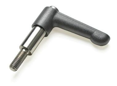
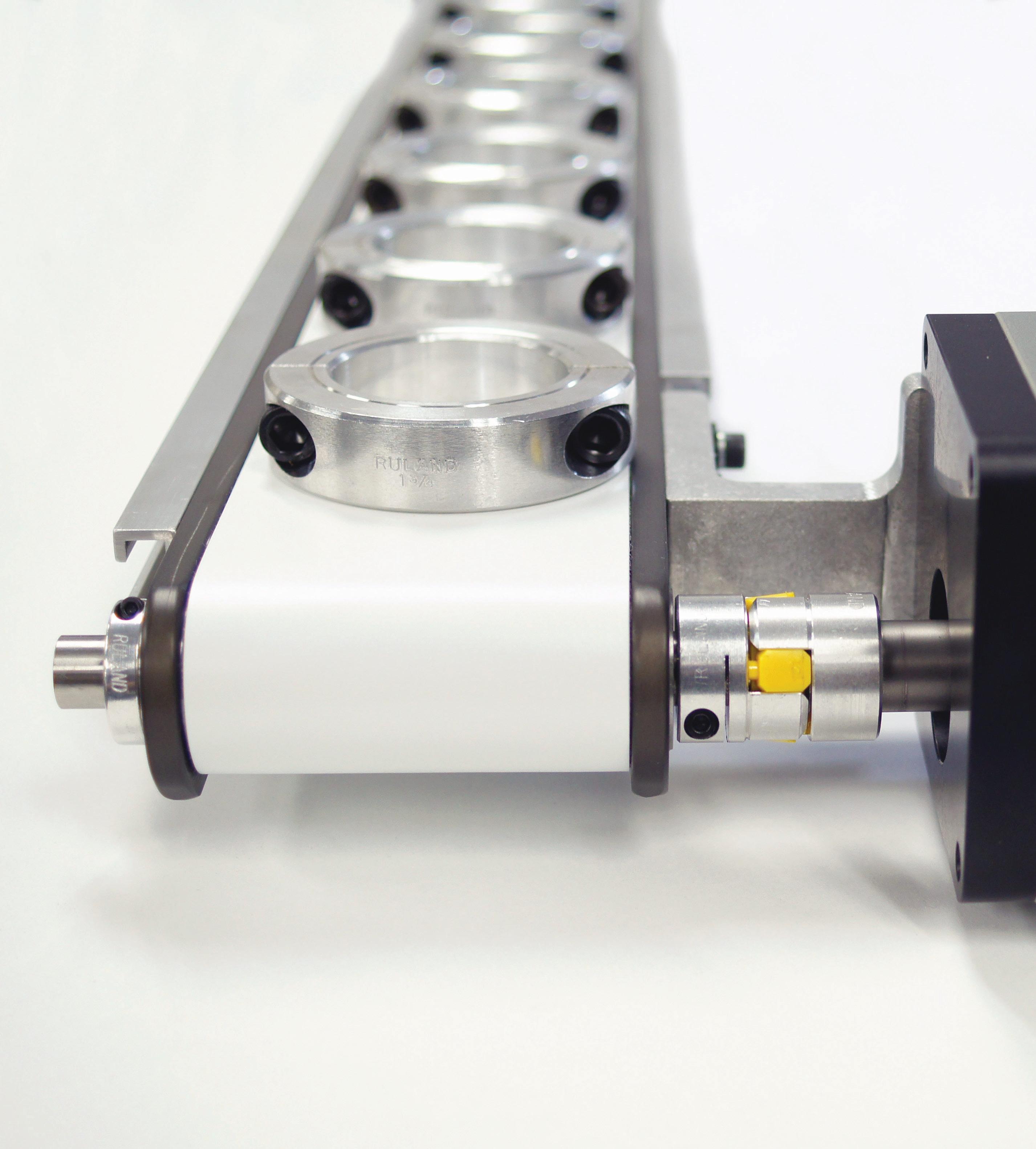
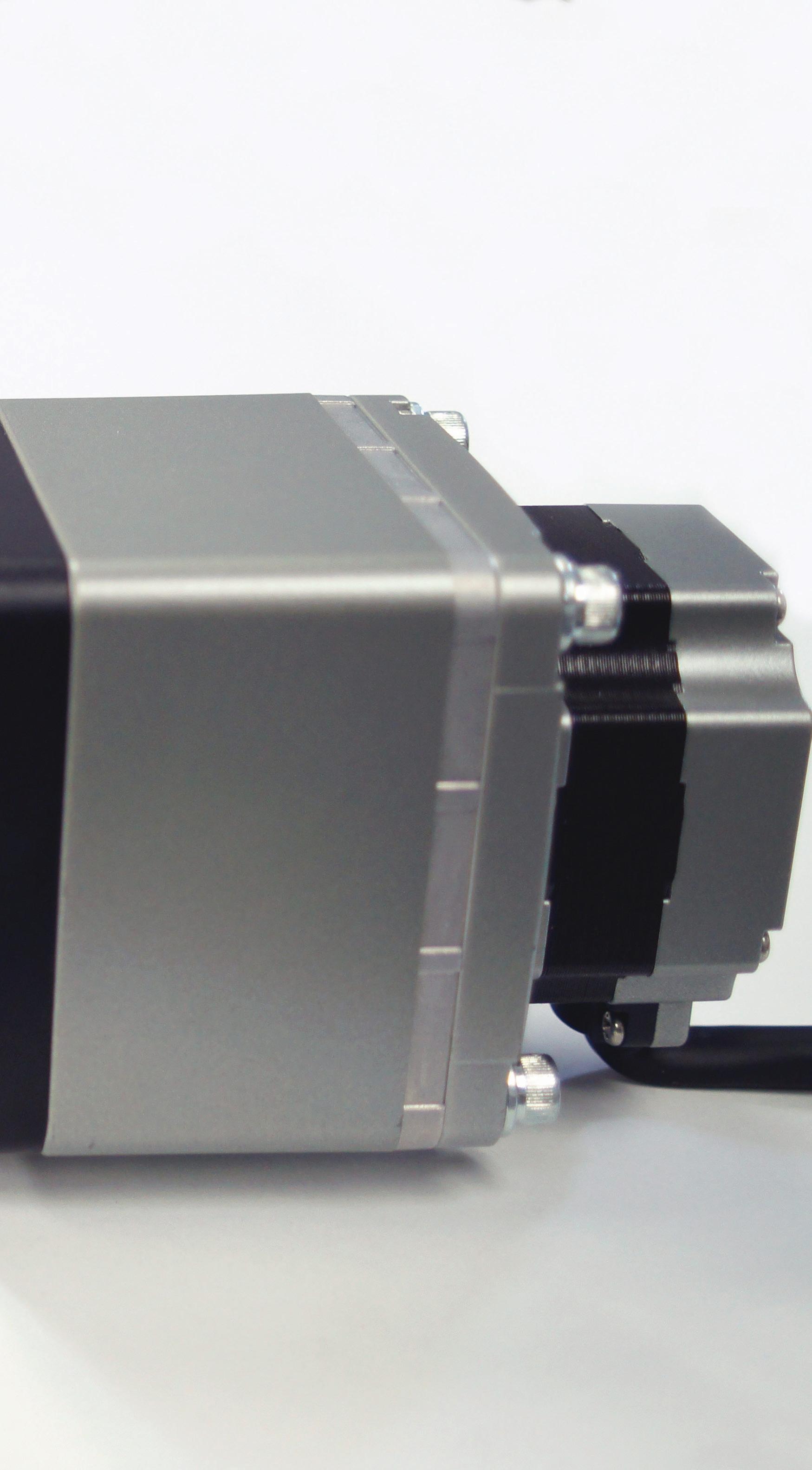
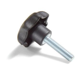
• Adjustable handles and knobs replace standard hardware and can be used to torque components without tools.
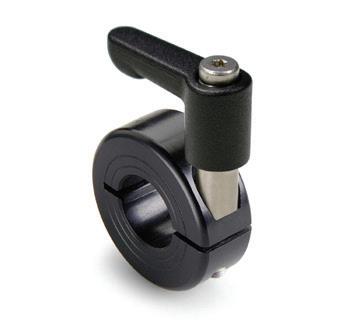
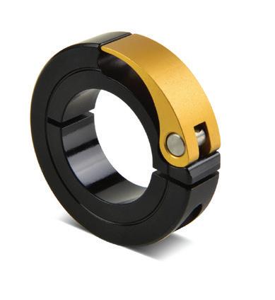
• Levers can be used with Ruland shaft collars for quick installation and adjustment.
All products available directly on RULAND.COM
• Beam couplings accommodate light weights and high misalignment.
• Zero-backlash jaw couplings for vibration dampening and a variety of performance options.
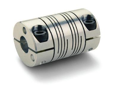
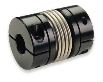
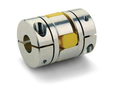
• Bellows couplings for high size to torque ratio.
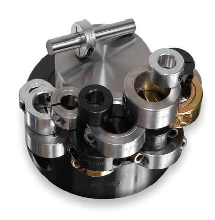
Ruland Manufacturing is proud to support the FIRST Robotics Competition as a Gold Supplier of precision shaft collars & couplings.
• Thousands of size and style options.
• Proprietary manufacturing processes ensure superior fit and finish.
• 8 material options.
• Rubber bumpers are ideal as end stops or mounting feet.
• Vibration isolation mounts can be sandwiched between components to dampen shock loads.
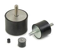
• Both types can have studs or tapped holes.
• Assorted components allow you to build small assemblies for mounting sensors, conveyor rails, machine guards, and more.
• Optional pre-designed kits make it easier to select the right system for your application.
• No tools required to install, remove, and adjust.
• Best suited for systems that require frequent adjustments.

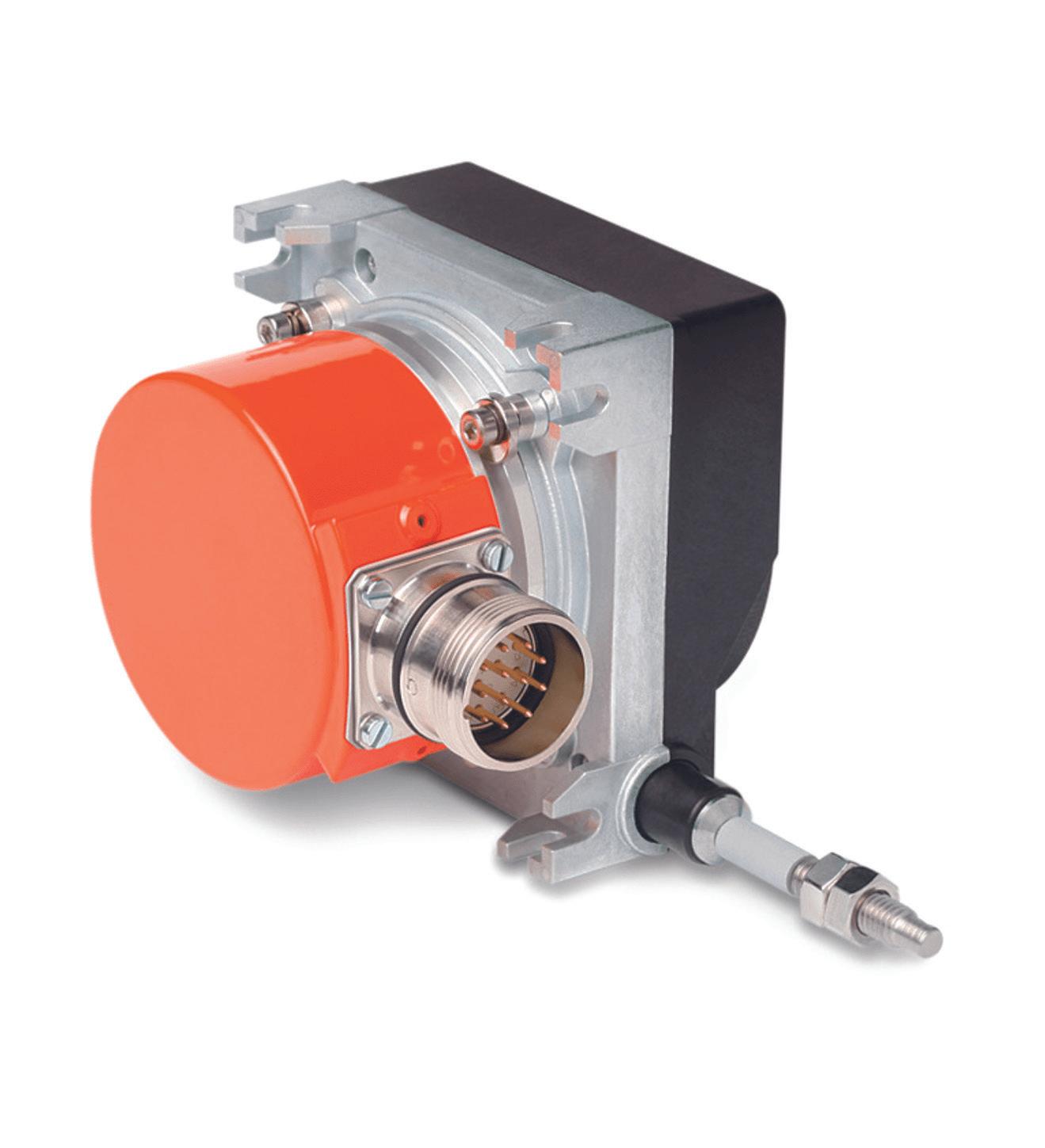
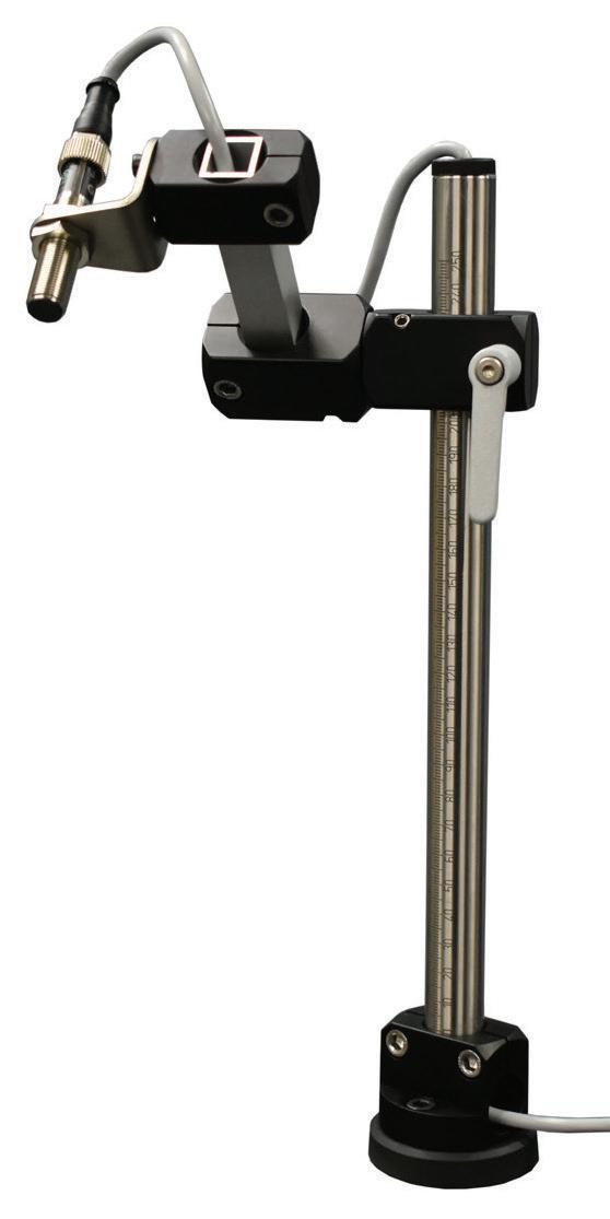
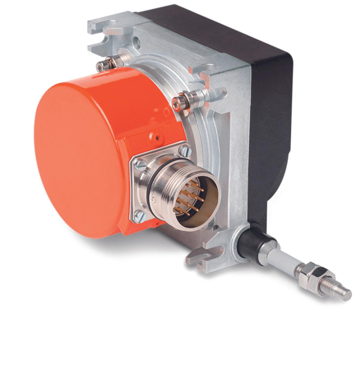
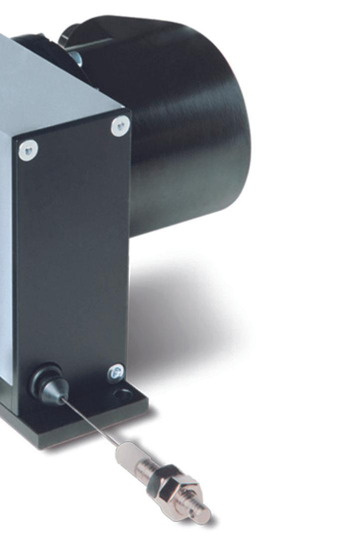
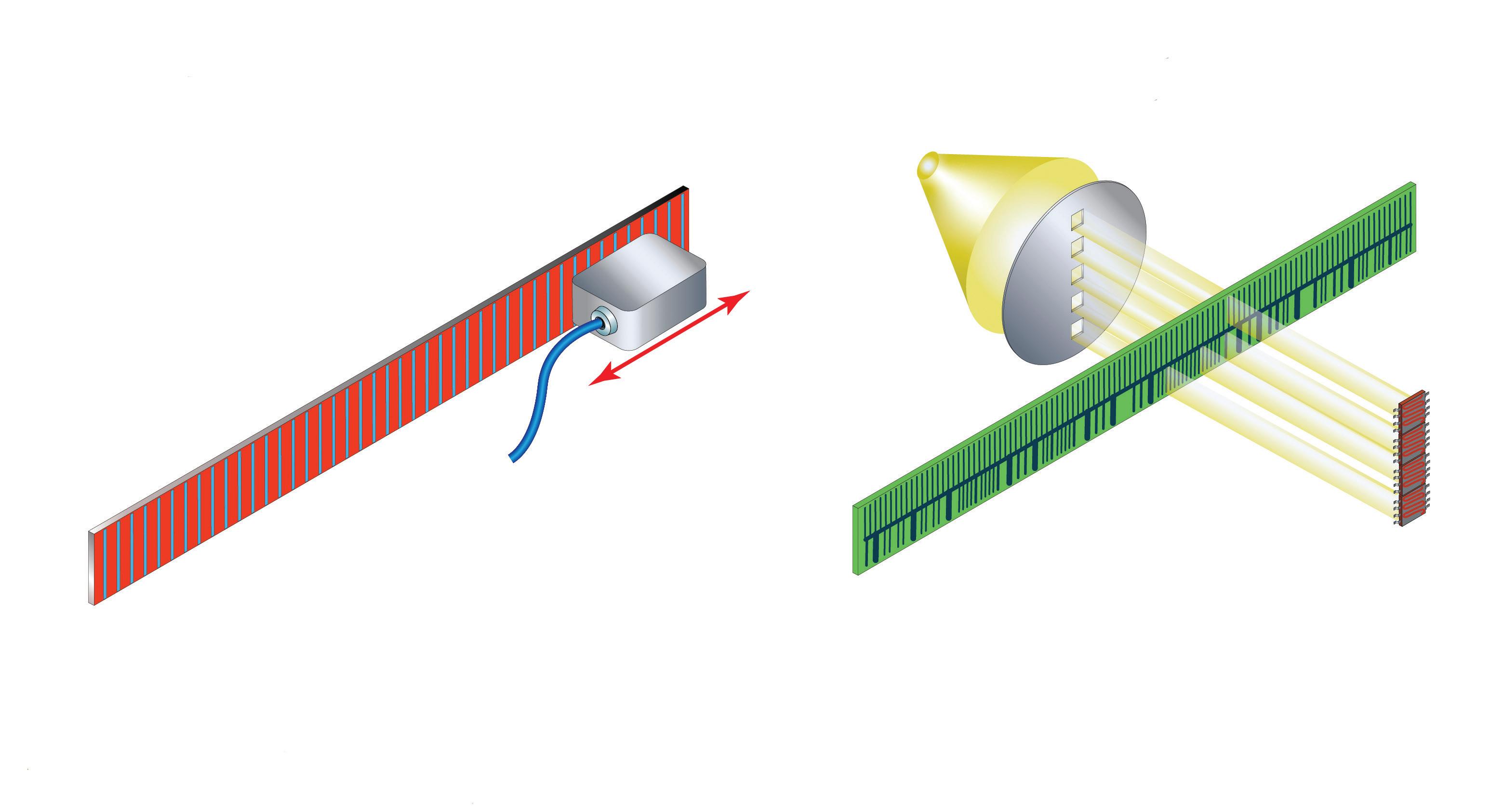
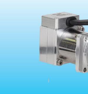
Another way to measure both position and speed involves using draw-wire encoders. For example, the PURE.MOBILE series SG31 and SG61 wire-actuated encoders from SIKO can measure up to 6 m and integrate an inclinometer, combining the ability to detect both position and speed as well as inclination.
Measuring position and speed is a primary task in motion control applications. There are a number of ways to do this, depending on the application needs, environmental considerations, and other design factors. And while it’s true that encoders mostly are used to measure position, they can also be used to measure speed.
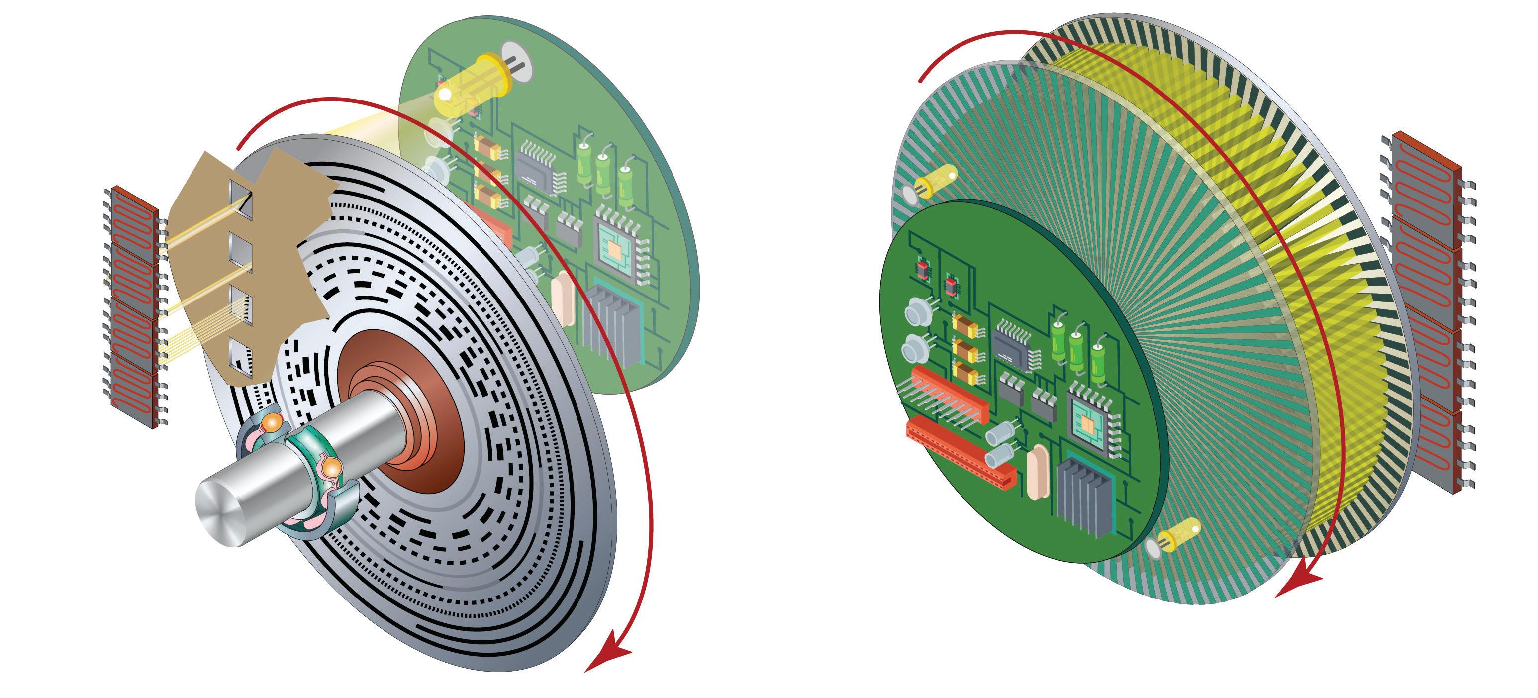
Encoders and resolvers are used to track the angular or linear position of an object, such as a motor shaft (angular measurement) or a linear actuator (linear measurement). And with the addition of a clock signal, encoders and resolvers can also be used to measure the speed of the object.
A resolver uses a rotor with a primary winding and a stator with two secondary windings, phased 90 degrees apart. When voltage is applied to the primary (rotor) winding, it induces voltages in the stator windings. These voltages are equal to the reference voltage multiplied by the sine or cosine of the shaft’s angle from a zero point. The speed of the resolver (and of the shaft to which it’s attached) can be found by simply taking the rate of change of either secondary signal (the sine or the cosine signal). Resolvers can generate a single electrical cycle per
mechanical revolution (known as single-speed resolvers) or multiple electrical cycles per revolution (known as multi-speed resolvers). Speed measurement can be achieved with either design, although multi-speed resolvers provide more accurate speed information (at the expense of absolute position information).
Encoders can provide either incremental or absolute position information, and those that supply incremental position can do so by using either square wave (TTL) signals (typically referred to as “incremental encoders”) or sine-cosine signals (typically referred to as “sin-cos encoders”). By analyzing the position information relative to a clock signal, any of these encoder types can be used for speed measurement. However, incremental (TTL) encoders are the most common design used for measuring speed — using either the pulse frequency or pulse period method.


Another way to measure speed in motion applications is using Hall-effect sensors. Hall-effect sensors are used in industrial and motion-control applications with low dc voltage and current values. These sensors are common in high-speed applications such as rotary speed tracking on linear conveyors.

How do they work? The Hall effect is an outcome of the Lorentz force at work.
When a thin conductor (or semiconductor) has a steady flow of current running through it and a magnet is placed so that its magnetic field runs perpendicular to this current, the magnetic field of the current reacts to the magnetic field of the permanent magnet, causing the electrons flowing through the conductor to be pulled to one side of the conductor, due to the Lorentz force. This creates a potential difference, referred to as Hall voltage, in the conductor. The magnitude of the Hall voltage is proportional to the strength of the magnetic field. The Lorentz force is the force that a particle experiences due to electrical and magnetic fields. The Hall effect is put to use in sensors, where the resulting Hall voltage can indicate the presence, absence, or strength of a magnetic field. Although Hall sensors operate by detecting a magnetic field, they can be used for sensing a wide variety of parameters, including position, temperature, current, and pressure.

Hall effect sensors are typically divided into two categories: digital Hall effect sensors — which include Hall effect switches and Hall effect latches — and analog Hall effect sensors.
Hall effect switches — also referred to as unipolar sensors — detect the presence (or absence)

of a magnetic field as compared to a predefined threshold for magnetic flux. When a suitable magnetic field is detected, the switch turns on (closes), and when the field is removed, the switch turns off (opens). Proximity sensors are a common application for Hall effect switches.
The operation of a Hall effect latch — also referred to as a bipolar sensor — is similar to a switch, but a latch turns on (closes) when a positive magnetic field is applied and remains on even when the field is removed. Conversely,
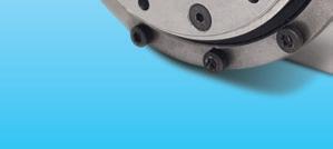
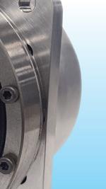
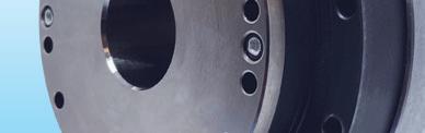
Some of the most common encoder sensing technologies include optical and magnetoresistive (pictured here), which can be implemented in the two types of encoders, being absolute or incremental.
the latch turns off (opens) when a negative magnetic field is applied and remains off even when the field is removed. Hall effect latches are commonly used in brushless dc (BLDC) motors to detect rotor position for proper commutation.
Digital Hall effect sensors incorporate a Schmitt trigger — a circuit that adjusts the switching threshold to a slightly higher point on the rising edge of the signal and to a slightly lower point on the falling edge of the signal. The difference between these switching points is referred to as hysteresis,
and ensures that the switch will not oscillate, or switch on-and-off, due to noise in the input signal.
Analog, or linear, Hall effect sensors produce a continuous output voltage proportional to the magnetic flux density (strength of the magnetic field), which makes them suitable for measuring position and movement. In fact, many magnetic rotary encoders use linear Hall effect sensors. However, the interaction of the flowing current and the magnetic field produces a Hall voltage that is very small, so linear Hall sensors
typically incorporate an amplifier to increase the output voltage, along with other signal conditioning electronics to improve the sensor’s response and compensate for temperature effects.
Hall effect devices make excellent sensing elements because they’re completely noncontact and have no moving parts, giving them a long operating life. And they can operate at high speeds and switching frequencies with excellent repeatability.
Key technology content produced by the editors of Design World compiled in individual design guides. Collect these free technical PDFs!
GEARMOTORS
HUMAN-MACHINE INTERFACES (HMIS)

Find these and additional guides in our DESIGN GUIDE LIBRARY, bookmark this site as guides are added on an ongoing basis! designworldonline.com/design-guide-library
SERVOMOTORS

COUPLINGS
 BROUGHT TO YOU BY:


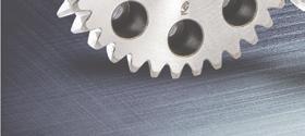
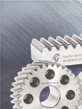
CGI Motion standard products are designed with customization in mind. Our team of experts will work with you on selecting the optimal base product and craft a unique solution to help di erentiate your product or application. So when you think customization, think standard CGI assemblies.

Connect with us today to explore what CGI Motion can do for you.


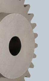
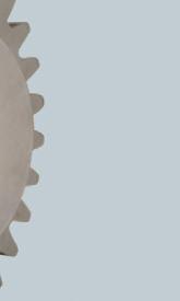
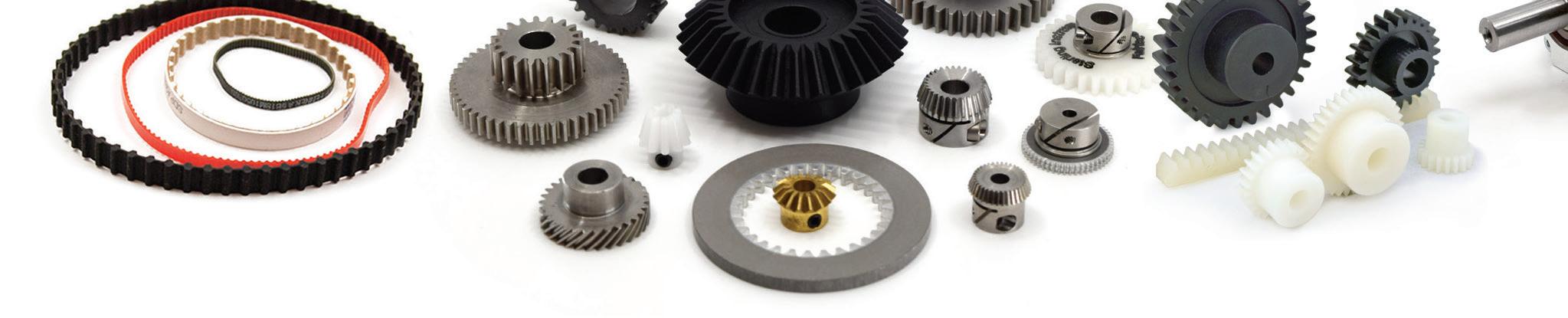
In motion control systems, gears are used to change the torque and speed delivered by a motor to a driven component. Depending on how the gears are arranged, they can either increase the delivered torque and decrease the output speed (the most common arrangement in motion control applications) or decrease the delivered torque and increase the output speed. Gears can also help to improve the load-to-motor inertia ratio by reducing the amount of load inertia reflected to the motor. This allows the motor to better control the load and improves characteristics of system performance such as settling time.
The relationship between the input speed to the gearbox and the output speed delivered to the driven load is commonly referred to as the gear ratio. One of the simplest ways to determine the gear ratio is to take the ratio of driven gear teeth to driving gear teeth.
For example:
z2 ω1 = —
z1 ω2 where:
z1 = number of teeth on driving gear
z2 = number of teeth on driven gear
ω1 = speed of driving gear
ω2 = speed of driven gear
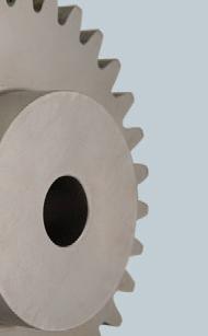
To achieve torque multiplication and speed reduction, the driving gear (also referred to as the pinion) will be smaller than the driven gear (typically referred to as simply the “gear” or “wheel”).
This is easy to imagine if one pictures a driving gear (pinion) with 20 teeth and a driven gear with 40 teeth. For every one revolution of the driving (20-tooth) gear, the driven (40-tooth) gear will only complete ½ revolution. In other words, the smaller, driving gear will turn twice for every one revolution of the larger, driven gear.
the input is simply the product of all the intermediate gear ratios. For example, if a three-stage gearbox consists of a first stage with a 10:1 gear ratio, a second stage of 5:1, and a third stage of 3:1, the total transmission ratio will be 150:1.
Expressions of gear ratio are typically factored down so that the denominator (representing the number of teeth on the driving pinion) is expressed as “1,” even if that means the numerator (representing the number of teeth on the driven gear) would result in a decimal. For example, if a driven pinion has 21 teeth (z2 = 21) and a driving pinion has 9 teeth (z1 = 9), instead of 21:9 or 7:3, this gear ratio will typically be expressed as 2.3:1.
Per the ISO 701:1998 standard, gear ratio is denoted with the letter “u” and total transmission ratio — the total ratio of input speed to output speed — is denoted with the letter “i.” In this notation, the denominator of the ratio is set to 1, and only the numerator is expressed. So, an 11:1 ratio would be expressed as i=11, and a 2.3:1 ratio would be expressed as i=2.3.
The calculation of transmission ratio for a single-stage planetary gearbox depends on which gears are the driven, stationary, and output components. In motion control applications, planetary gears typically have a driven sun gear, a stationary ring gear, and a carrier that drives the output shaft. For this configuration, the total transmission ratio (ip) is equal to one plus the ratio of ring gear teeth (zr) to sun gear teeth (zs), or ip = 1 + zr /zs
This configuration gives a gear ratio of 2:1, which means that the speed from the motor is reduced by a factor of 2 and the torque from the motor is multiplied by a factor of 2 (not accounting for any losses due to inefficiencies in the gear train).
For multi-stage gearing, the gear ratio between the output and
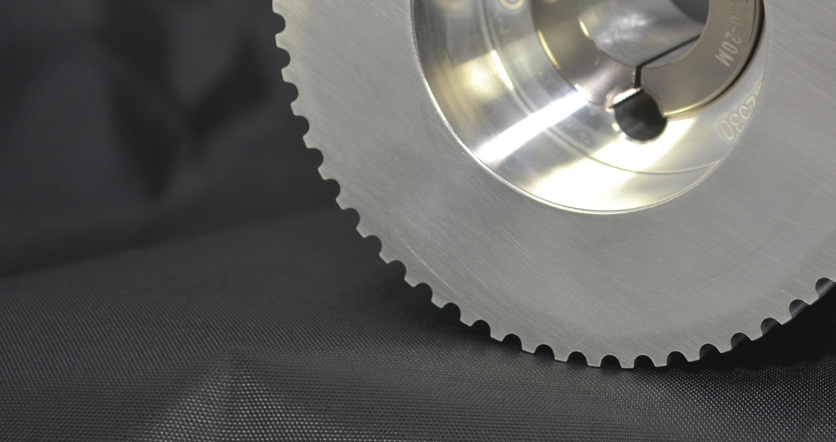
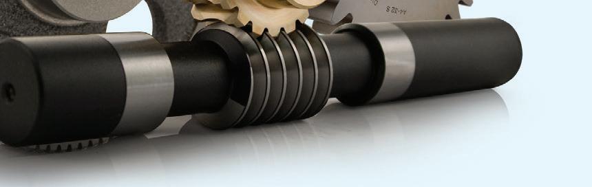
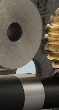
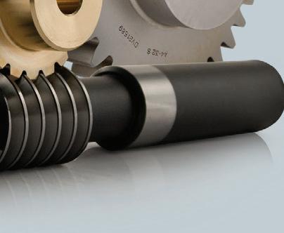
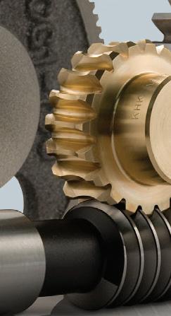
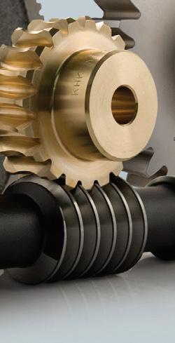
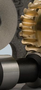
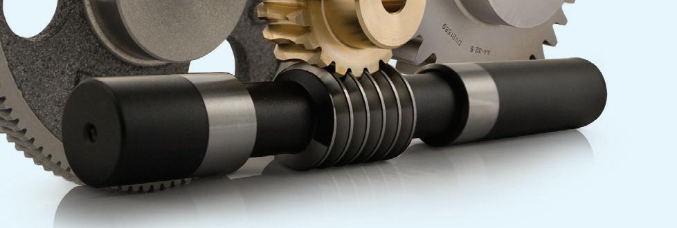
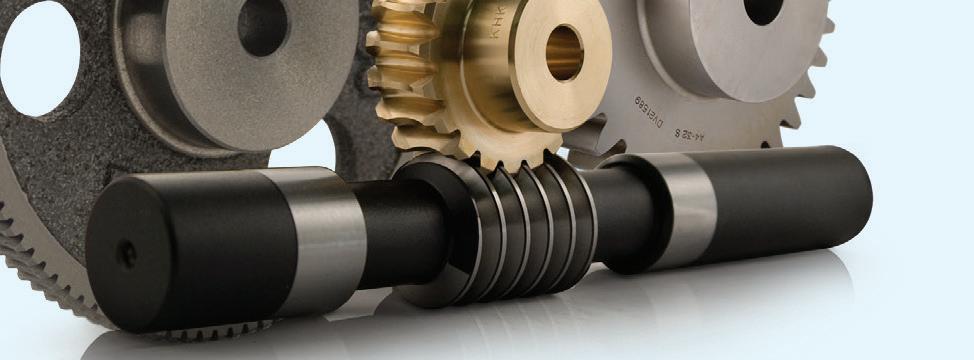
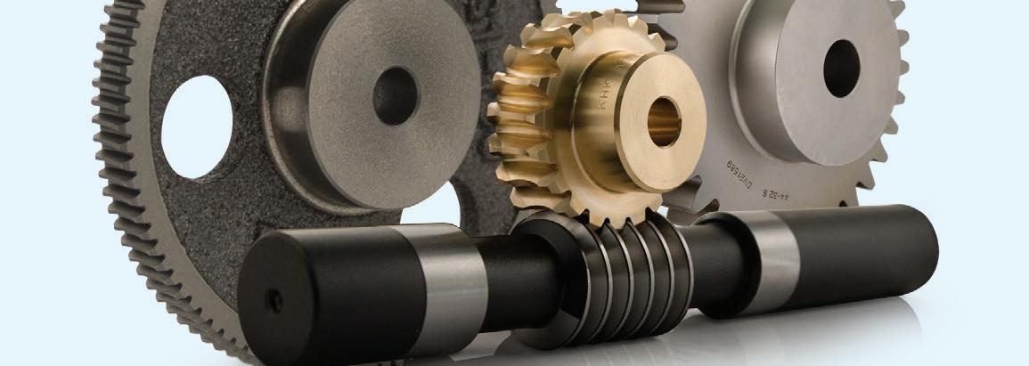
For worm gears, the gear ratio equals the number of teeth on the gear divided by the number of starts on the worm.
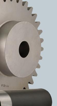
In gearboxes using spur, helical, or bevel gears, the gear ratio — the amount of torque multiplication and speed reduction — is simply the
ratio of the number of teeth on the driven (larger) gear to the number of teeth on the driving (smaller, or pinion) gear.
In theory, any gear ratio could be obtained by adjusting the number of teeth on the driving and driven gears, but in real-world operation, high gear ratios introduce design challenges — such as the need for a very small pinion (driving gear), high stresses on gear teeth, and limited torque transmission capabilities. Fortunately for machine designers, these challenges can be easily addressed with a multistage gearbox.
A multi-stage gearbox simply combines two or more pairs, or stages, of gears, with the output of one stage connected to the input of the next. The resulting gear ratio is the product of the gear ratios of each stage. For example, a two-stage gearbox consisting of one stage with a 5:1 gear ratio and a second stage with a 3:1 gear ratio provides an output ratio of 15:1 (5 x 3), so the torque delivered to the load is 15 times higher than the torque provided by the motor — not including transmission losses — and the speed delivered to the load is 1/15 the speed of the motor.
Multi-stage gearboxes can — and often do — consist of different types of gearing at each stage. For example, a right-angle planetary gearbox can be constructed with a planetary stage and a spiral-bevel stage. The amount of reduction
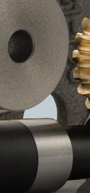
The product of number of teeth and rotational speed must be equal for both the driving and the driven gears. From this, we can see that the ratio of the number of teeth on each gear is equal to the inverse ratio of the speed of each gear. (Image courtesy of Precision Microdrives)
for each stage can be different, but multi-stage gearboxes are typically designed with a higher gear ratio at the input and a lower ratio at the output side.
The total efficiency of a multi-stage gearbox (or a suitable estimate) can be found by multiplying the efficiencies of each stage. And it’s important to note that each stage reverses the direction of rotation between the input and output — with the exception of a planetary stage, in which the direction of rotation is maintained between the input and the output.
For most single-stage gearboxes, the directions of rotation of the input and output shafts are opposite, while for two-stage gearboxes, the additional change in direction by the second stage puts the output shaft rotation the same as the input shaft.
Although efficiency is decreased to some degree, multistage gearboxes offer higher gear ratios than could be achieved with most single-stage gear designs. And they do so in a compact package that can be optimized to achieve the best combination of torque transfer capability, low inertia, and high efficiency.
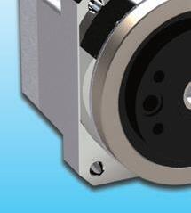
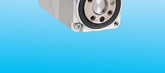
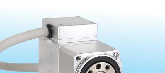
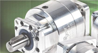
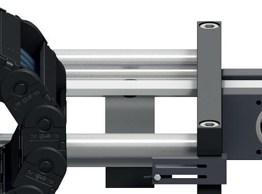
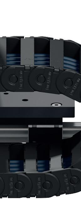
The IDT Series is a family of compact actuators with an integrated servo drive with CANopen® communication. They deliver high torque with exceptional accuracy and repeatability, and feature Harmonic Drive® precision strain wave gears combined with a brushless servomotor. Some models are available with a brake and two magnetic absolute encoders with the second providing output position sensing. This revolutionary product line eliminates the need for an external drive and greatly simplifies cabling, yet delivers high-positional accuracy and torsional stiffness with a compact form factor.
• Actuator with Integrated Servo Drive utilizing CANopen®
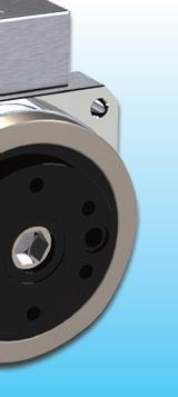

• 24 or 48 VDC nominal supply voltage
• A single cable with only 4 conductors is needed: CANH, CANL, +VDC, 0VDC
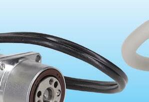
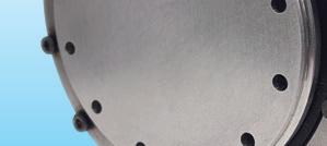


• Zero Backlash Harmonic Drive® Gearing
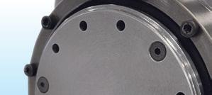
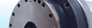
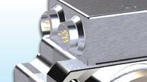
• Panel Mount Connectors or Pigtail Cables
Available with Radial and Axial Options


• Control Modes include: Torque, Velocity, and Position Control, CSP, CSV, CST


Rugged innovative gears and gearmotors along with other drive technologies rise to the challenge in demanding wood-processing applications.
 By Oscar Lopez • Service manager — industrial gearing | SEW Eurodrive


Applications in the timber industry are varied and demanding — consisting of debarking, sawing, drilling, milling, and grinding operations. The machines used in these processes and the components and systems driving them must be dynamic and powerful enough to withstand harsh conditions involving high shock loads, changing speeds, and long hours of operation. Most challenging of all is the presence of copious dust, dirt, and wood shavings.

Not all drive technologies are up to the challenge. That’s why it’s important to know the design criteria that can make or break performance in these applications and specify components balancing versatility, material strength, and contamination resistance.


Not all drive technologies can withstand the rigors of woodworking and wood processing applications. Fortunately, some gear units, gearmotors, and drive components are specifically designed to handle these and other heavy-duty processes.


Some gear suppliers have decades of experience designing mechanical components with the robustness to keep timber operations on track.
As we’ll explore, drive technologies suitable for timber-processing applications include helical and bevelhelical gears with invertible housing; large segmented girth gears made from austempered ductile iron or ADI; and gearmotors as well as screw conveyor drives with multiple sealing areas against contaminants. Recall from materialscience fundamentals that austempering is a type of heat treating of high-carbon iron to produce high-strength and tough bainites.
More timber throughput with versatile gearing Machines for wood processing, conveying, storing, and picking need powerful drives that are versatile and reliable. For a universal solution, certain industrial helical and bevel-helical gears having invertible housings that accommodate both left and right shaft positions. Such designs reduce gear variants needed and inventory costs. That’s because gearing that offers various mounting orientations reduces the number of spare drive packages stored onsite for maintenance.
Savings are even higher if a given drive powers several applications in a facility or several facilities. For example, one application’s bevel-helical gear unit might cost $18,000. If the application needs both left and right drives, a single drive that can install in both orientations can save up to $18,000 — and reduce the use of valuable storage space.
In fact, the modular nature of some such gearing allows millions of different configurations to let design engineers arrive at a drive solution to best satisfy application speed, torque, footprint, and environmental parameters. Customizable features include numerous shaft styles and wide gear-ratio ranges — 6:1 to 400:1 for example. Avoiding costly downtime in the timber industry
Gear options with top reliability are necessary in the timber and paper industries where even a few hours of downtime can lead to thousands of dollars in lost productivity.
After all, downtime can cost $10,000/hr to $400,000/hr or more in certain pulp and paper-mill applications. These costs far exceed those associated with removing and installing a replacement gearbox ... and the above are only readily calculable totals. Other costs of downtime include the payment of production personnel sitting idle and losses relating to a machine center that isn’t producing.

"How much torque does this design need? Beyond design flexibility and contamination, look for gear units that are high capacity. Gears capable of delivering up to 800 kNm can withstand the loads associated with many woodprocessing applications, which typically need 175,000 to 475,000 Nm.
This screw-conveyor drive includes multiple sealing areas to protect the gearing within. Optimized tooth-flank topology resists displacement for reliability even when external forces act on the shaft. In addition, the gears’ finely stepped sizes and torques boost both machine availability and uptime.
Many operations in the timber industry benefit from helical and bevel-helical gear units having the ability to bear high axial and radial loads. Some options include a single-piece block housing allowing horizontal, vertical, and upright assembly; optional motor adapters, backstops, sealing systems, shaft end pumps, and mounting maximize design flexibility. Where necessary, cooling systems engineered into the gearing solution can eliminate the need for a costly external cooling unit. Legacy products that have been in production for many decades (especially those with a large installation base) are often a suitable choice.
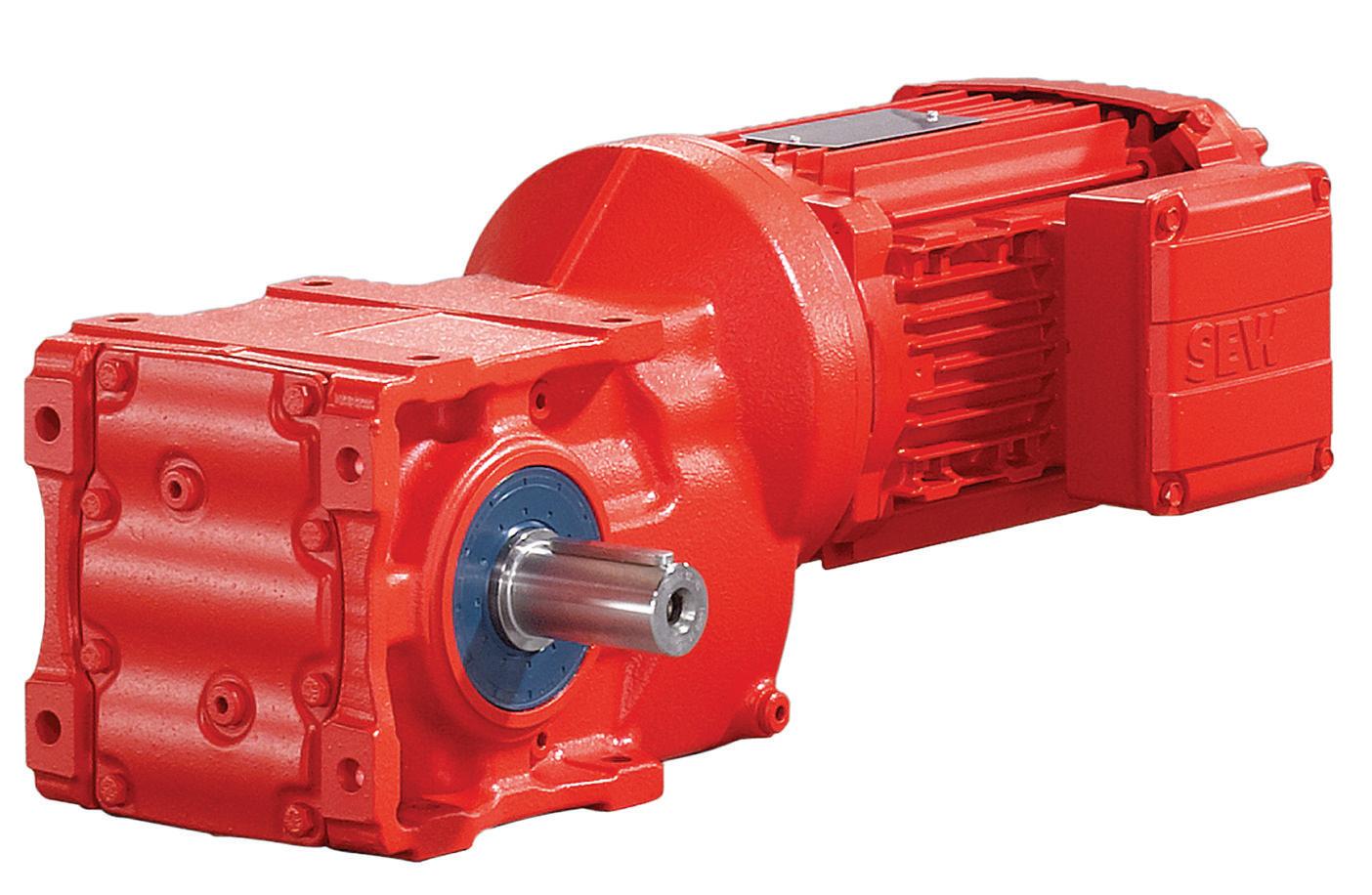
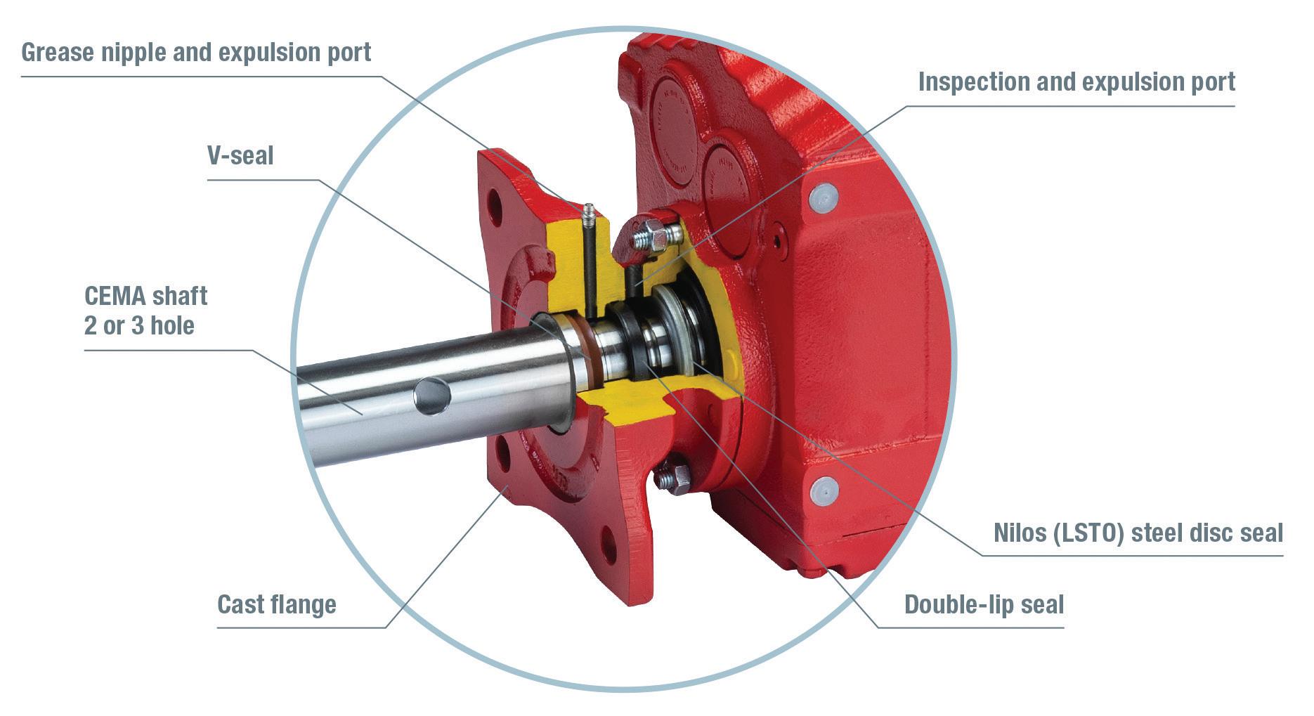
Industrial girth gears are indispensable in wood processing applications, as they often drive large rotating systems. Typical applications include lumber trommels, debarking mills, and digesters. These operations typically rely on two to four machine

segments that are assembled together. The catch is that the large gearing that goes into such equipment is typically made and heat treated on large and expensive machines. In addition to these challenges, the sheer size of traditionally design girth gears (7 to 15 m) can degrade gear casting and heat-treatment quality. Segmented girth gears avoid the drawbacks associated with traditional girth gears. For example, some girth gears include six to 14 identical segments that are relatively small and easy to handle, assemble, and install. Some segmented girth gears are also made from ADI mentioned earlier — a material defined by the International Organization for Standardization (ISO) and the American Gear Manufacturers Association (AGMA). Compared to traditional
K-series helical-bevel gearmotors combine high torque density and efficiency in a right-angle design. Instead of losing energy due to the sliding friction of the worm gear, these components experience a lower rolling friction of the helical and bevel gears — minimizing heat loss and maximizing energy savings.
girth gear materials such as ductile iron or cast steel, ADI is technologically advantageous for many reasons. No wonder some gearmotor suppliers employ proprietary ADI formulas to manufacture girth-gear products.
Standards specifying ADI mechanical properties include:
• AS A 897M-90 — the standard specification for austempered ductile iron castings.
• EN 1564:1997 — defining founding austempered ductile cast irons.
• ISO 17804 — classifying founding ausferritic spheroidal graphite cast irons.
• AGMA 939 — detailing austempered ductile iron for gears.
These gears incorporate a highly wear-resistant microstructure that achieves high tensile strength. ADI also features above-average contact fatigue strength due to its cold working properties. When combined with an appropriate girth gear size, these properties spur a lighter and more compact gear design compared to traditional materials. This lighter weight is important for handling and assembly purposes as well as the gear’s achievable (application-
specific) circumferential velocity. Generally speaking, the latter falls between two and 10 rpm for the final rim speed.
Other technological advantages of ADI girth gears abound.
Tight gear tolerances: Due to their multiple smaller segments, individual girth gear components can be machined to tighter tolerances. The overall gear is therefore more precise and wear-resistant which in turn increases its power density.
High gear-pitch accuracy: Girth gears with many segments guarantee an initial pitch accuracy that meets AGMA 9 standards. Thanks to its high dimensional accuracy, these components keep vibrations to a minimum during timber industry processes such as debarking, sawing, and shredding.
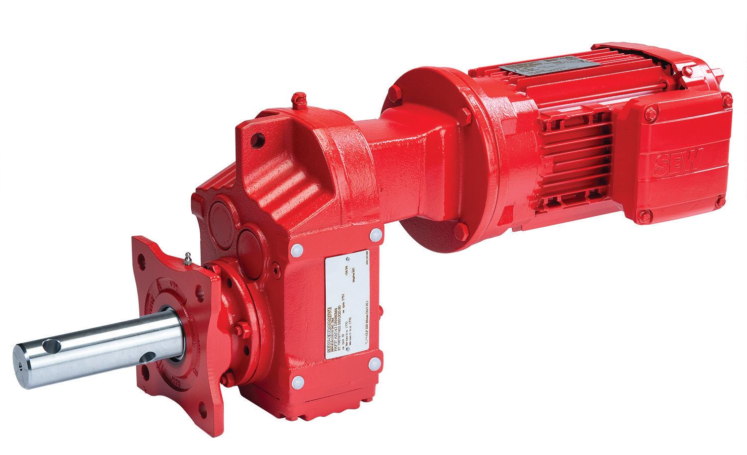
Superior gear casting: Segmented girth gears’ multiple smaller segments lend themselves well to high-quality casting — reducing the amount of stress concentrations that can arise as the casting cools.
Small gear faces: Each segmented girth-gear component has a smaller face than traditional gears of comparable design for lower material costs.
This also improves gear tooth contact, which typically becomes harder to maintain the wider a gear face gets. Once contact drops below 80% endusers must switch to using helical gears, which can drive up costs by 30 to 40%.
Easy handling and replacement: Handling gear segments is easy in the factory (during production) and at the gear’s installation site. There’s also no need to make any special transportation arrangements, as segmented girth gears can be transported in standard containers. If a segment is ever damaged, it can be easily exchanged without necessitating the dismantling of the whole gear ring.
These benefits render segmented girth gears a practical choice for woodworking and woodprocessing applications as well as similarly heavy-duty industries such as mining, energy, pulp and paper, steel, and cement. With the correct dimensioning, load, and lubrication, ADI girth gears are virtually wear-free … even under the harsh operating conditions of these industries.
Sealing to prevent contaminationAs mentioned, timber-industry processes involve trying conditions such as outdoor operation and the presence of dust, dirt, and wood shavings. So, it’s important to select drive
technologies that integrate multiple sealing features. For example, some gearmotors have reducers with an interlocking two-piece seal design along with a patented bi-helix fluoroelastomer (FKM) inner seal and double-lip nitrile outer seal. This creates a total of three sealing surfaces to keep out contaminants. The result is gearing for timber transportation lines and debarking machines that can withstand operation outdoors without adding anything to overall load.
It’s not just gearmotors that should sport advanced sealing features. Screw conveyor drives (used to convey sawdust and wood chips) should also feature such sealing. Some such drives include the following for extra protection against contaminants and abrasives:
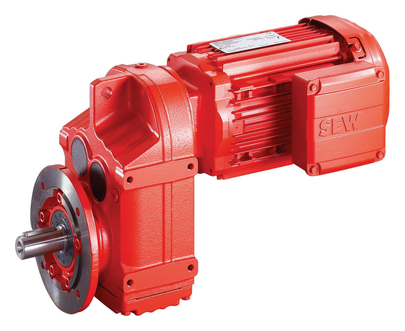
• A double-lip seal in the flange
• A double-lip seal on the gear unit output shaft
• A labyrinth seal on the output shaft formed by the V-ring and flange
Finally, some screw conveyor drives include an expulsion port that provides a grease channel to the V-ring and oil seal, as well as a path for excess grease to purge freely during regreasing. That prevents high pressures that can destroy seals.
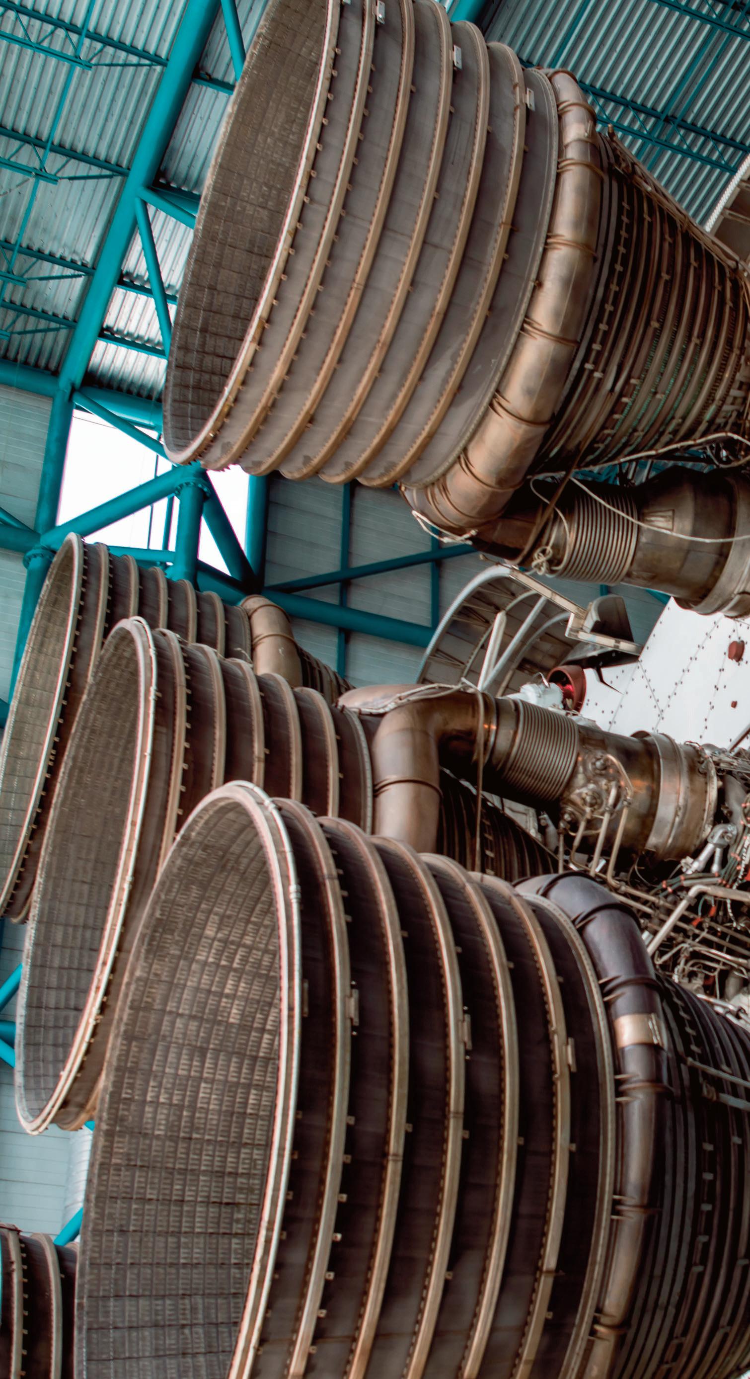
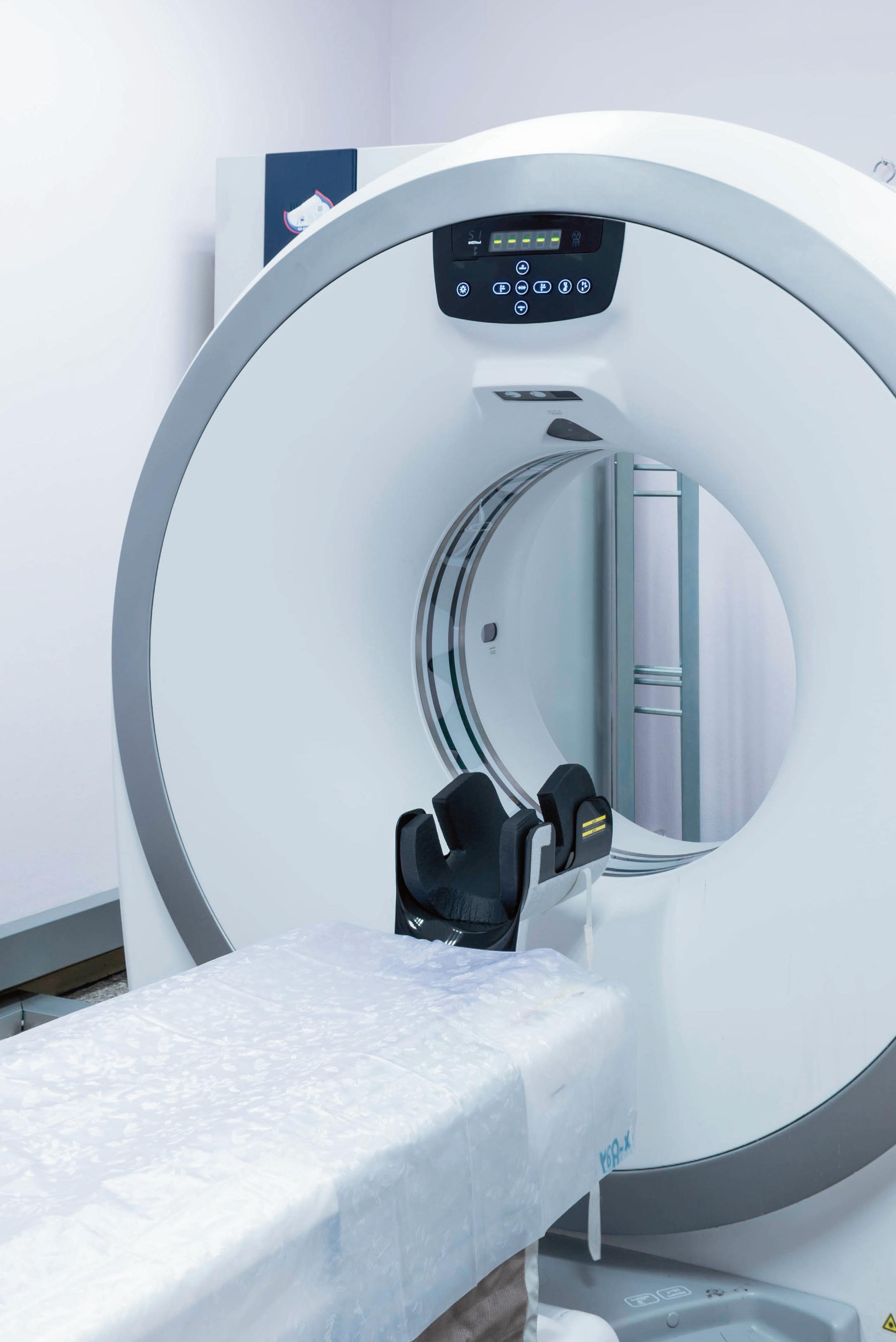

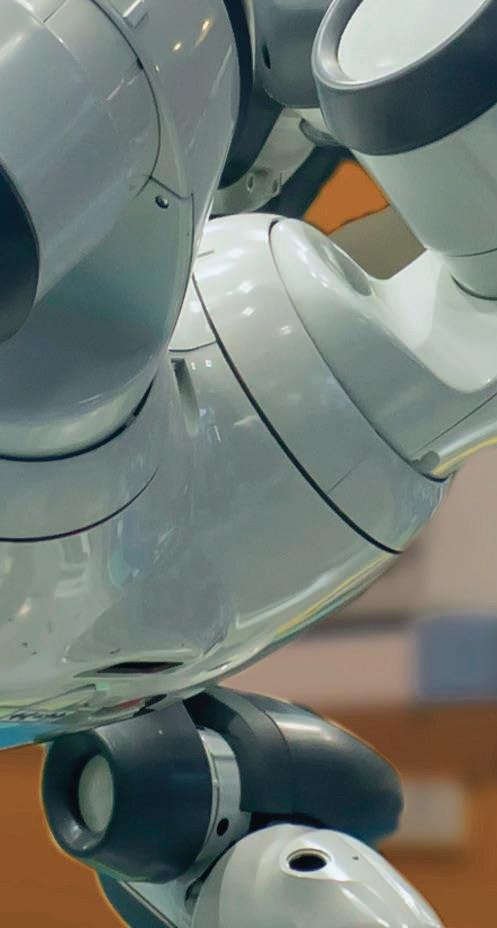


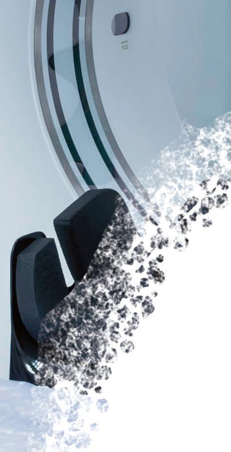


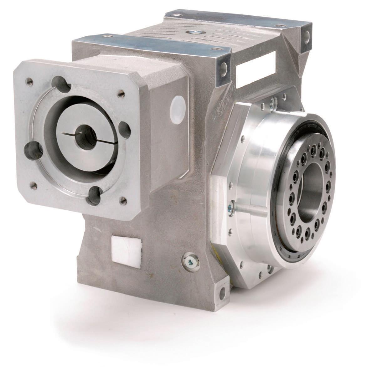


Motion is present in almost all industrial automation systems. Stopping or changing the direction of motion releases kinetic energy, which can cause shock and vibration. Any sudden shock in a system can cause immediate damage to the overall machine and the components it may be manufacturing or processing.
What’s more, consistent vibration inputs can cause damaging fatigue over time. Vibration in industrial machinery often originates from imbalances inherent to motors, gearboxes, and other turning components that excite natural frequencies.
This is why it’s necessary to decelerate a system smoothly through the use of shock and vibration absorbers.
Based on the type of inputs present in the application, vibration and shock attenuation components can be comprised of shock absorbers, linear dampers, wire rope or spring isolators, elastomeric isolators, air springs, or structural damping treatments. These devices help manufacturers reduce equipment downtime and costly cycle time limitations.
These products can be used in a broad range of applications, from the rate control mechanisms that slow the motion of the overhead luggage bin or seat recline on commercial aircraft, to the isolators which keep GPS systems from losing signal or becoming damaged on farm and construction equipment as they harvest crops or pave roadways.


Most shock absorbers achieve their damping characteristics through the use of hydraulic fluids. The fluid is pushed by a piston and rod through small orifice holes to create damping, and this action compresses some type of gas. This in turn creates a spring force to return the rod back to its starting position when the load is removed.
Shock absorbers and dampers are generally made of high-strength steel to handle the pressures from the internal hydraulic forces. Elastomeric seals prevent the fluid from leaking out of the cylinder, and special plating and coatings keep the units protected from harsh operating environments.


Recent and ongoing developments in sealing technologies and in the internal designs of shock absorbers and dampers have allowed for longer service life and more compact designs. Ongoing research in the field of noise attenuation (high frequency, low amplitude vibration) has led to an increased effectiveness in noise reduction technologies.
A unique application for these types of hydraulic damping devices has come with the increased awareness for seismic and environmental protection of infrastructure such as buildings and bridges. By adding damping to these critical
structures, energy is absorbed by the hydraulic devices instead of damaging the structure.
Vibration isolation products rely generally on mechanical designs to achieve their isolation characteristics. A spring function provides support for the mounted equipment, while decoupling it from the vibration source. Friction and elastomeric material properties give the isolators their damping characteristics.

Isolators can be made from a variety of materials. Wire rope and spring isolators can be made from carbon steel, stainless steel, or aluminum. Elastomeric isolators generally have metallic components that function as mounting brackets, separated by an elastomeric material that provides the stiffness and damping desired. Common elastomeric compounds include natural rubber, neoprene, and silicone; however, a vast selection of compounds and compound blends can be used to achieve different characteristics specific to the application.
Air springs are comprised of metallic end fittings coupled by a composite elastomericbased bladder that contains the compressed air used to provide isolation. These single-acting designs are comprised of a pressurized bladder and two end plates. As air is directed into the air bladders, they are expanded linearly.
All of these reusable designs are selfcontained, offering a number of advantages over any other technology that may require outside componentry. For example, hydraulic systems may require plumbing while electrical systems may require wiring and power.
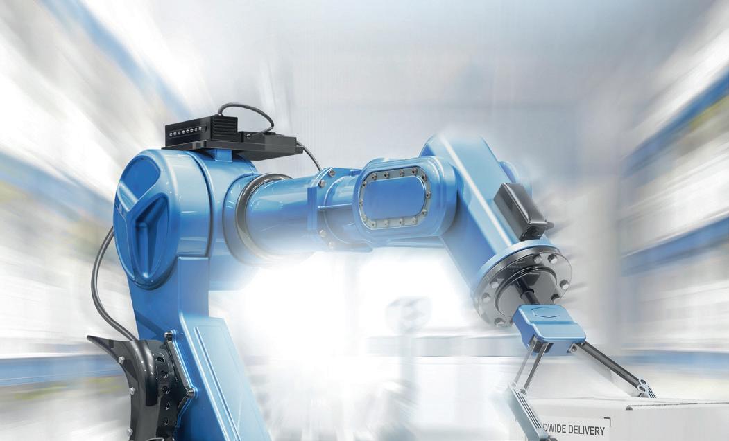
Energy or power dissipation is key when


selecting a damper or shock-absorbing device. The size and characteristics of the device are based on these inputs, so it is generally the first consideration to make.
Dynamic spring rate and damping are the two biggest considerations when selecting an isolator. These characteristics will define the natural frequency (sometimes referred to as resonant frequency) of the isolation system and are important in achieving the target performance.
Machine vibration is a normal, and typically unavoidable, result of moving and rotating parts, often caused by standard manufacturing and assembly tolerances that lead to clearances between mating parts or imbalances in rotating parts. And while routine machine wear can cause vibration to increase over time, when a machine experiences a significant or sudden increase or change in vibration, this can be an indicator that something is wrong and the machine or its components are being subjected to increased forces, loss of stiffness, and premature wear.
Although it’s not difficult to detect when vibration is approaching (or has reached) detrimental levels, pinpointing its causes can be challenging, since numerous components and operating factors contribute to a machine’s vibration. But an analysis of the vibration’s frequency and amplitude can help engineers and technicians root out the causes of worrisome vibration and determine its severity. Here are some of the key parameters for evaluating machine vibration:

WAY TO LIFT AND LOWER
• Enhance operator and machine control through the entire range of motion without excess strength

• Perfect support of muscle power with forces from 2 to 2,923 lbs.
• Stainless steel options for wash down and sterile environments


• A variety of accessories allows for universal application

INDUSTRIAL GAS SPRINGS ARE THE SMARTWire rope isolators, such as those pictured from ITT Enidine, have stainless steel cable and RoHS compliant aluminum retaining bars. They are corrosion resistant, which makes them environmentally stable and high-performance in a variety of applications.
technologies the potential causes of vibration, because every part vibrates at a distinct frequency or frequency range.
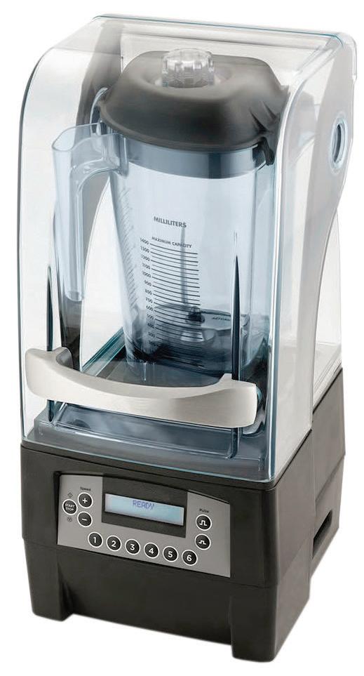
Vibration amplitude
Amplitude defines the magnitude of the machine’s oscillation and is used to judge the severity of the vibration. Oscillations with large amplitude indicate that the vibratory movements are large, fast, or forceful, resulting in more stress on the machine, components, and structure. Amplitude can be measured and specified for three aspects of oscillation: displacement, velocity, and acceleration.
Displacement amplitude
Note the differences in damping as expressed as stopping force to stopping stroke. When slowing moving masses with constant force through a stroke, industrial shock absorbers excel.
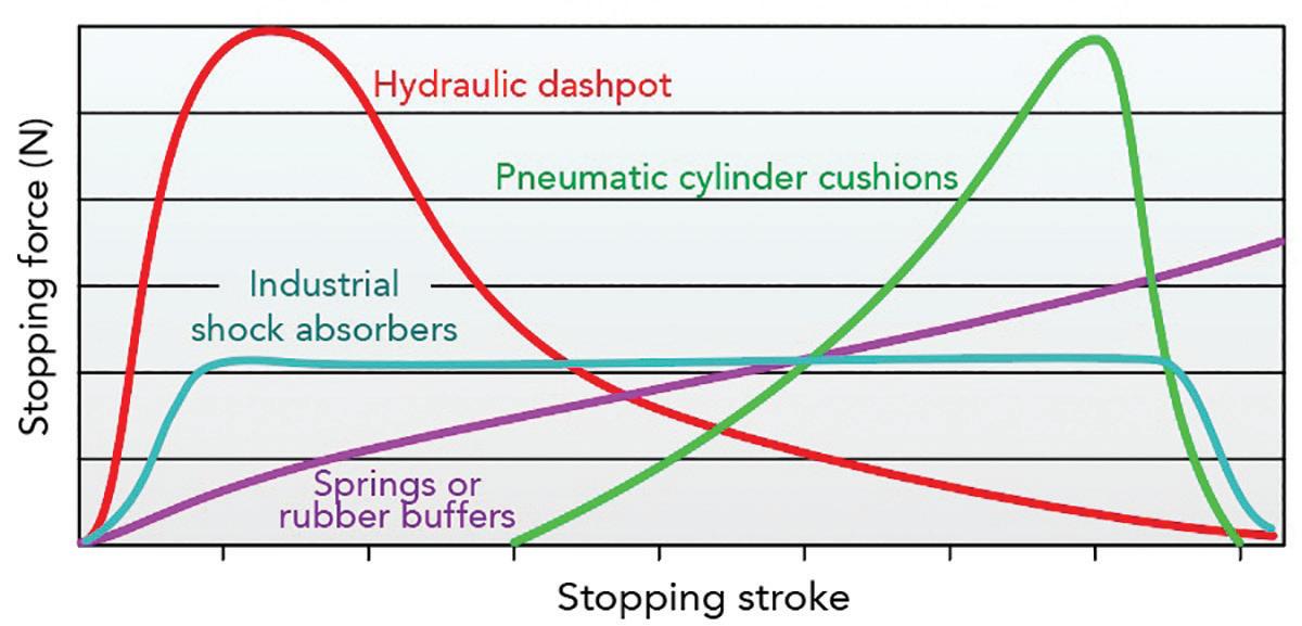
Vibration frequency
Frequency indicates the number of times an object oscillates, or vibrates, per unit of time and is often expressed in either cycles per second (referred to as Hertz, Hz) or cycles per minute (CPM). Frequency is probably the most fundamental parameter in machine vibration analysis. It is especially useful for narrowing down
Displacement amplitude measures the distance the vibrating part travels in one direction from a reference position during oscillations. (Note that the peak-to-peak displacement value, which measures total travel in both directions, is sometimes used.) This vibration measurement is important because vibrations with a high displacement amplitude can cause machine components to exceed their yield point and experience catastrophic failure. Displacement measurements are typically used when vibration frequencies are low.
Velocity amplitude
Velocity amplitude measures the speed of the oscillation. This measurement is typically considered the industry standard for evaluating the condition of a machine based on its vibrations, because it takes into account both vibration frequency and displacement. (Recall that velocity is the rate of change of displacement.) In fact, ISO standards refer to velocity amplitude when specifying the severity of machine vibration. Velocity amplitude can be expressed in terms of peak value or, more often, in terms of the root mean square (RMS) value, which is an indicator of the vibration energy.
Acceleration amplitude is directly related to the force imparted by the vibration and is especially useful for assessing the likelihood of fracture for equipment that rotates at high speed. The high forces associated with acceleration can also cause lubrication breakdown, which can lead to excessive wear, heat, and premature failure. Acceleration is typically measured in “g,” or multiples of earth’s gravitational acceleration.

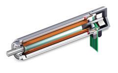
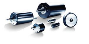
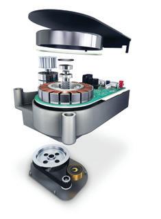
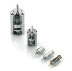


In recent years, industrial electronics suppliers have supported efforts to simplify control-cabinet setup with Actuator-Sensor or AS-Interface connections. These solutions can often replace messes of wires with clean and uncluttered cabling.
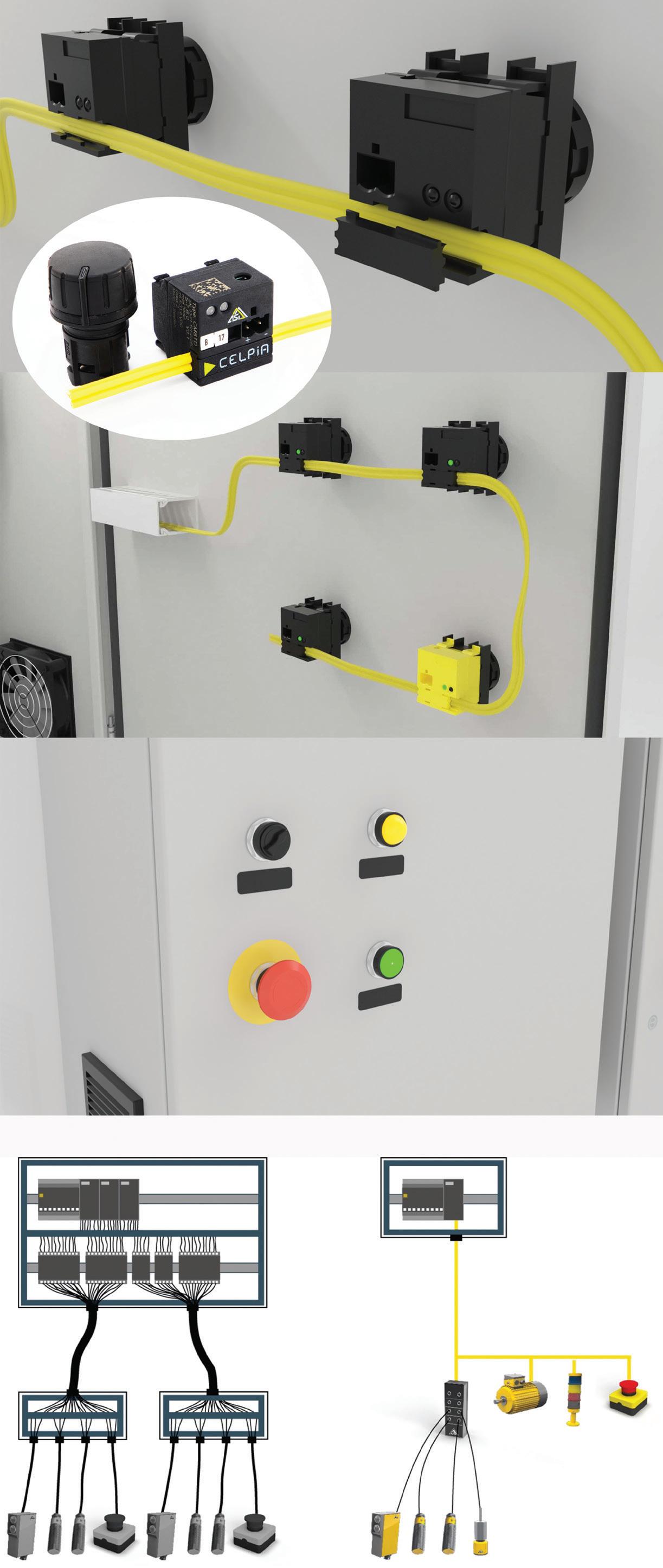
Well-established in Europe, the U.S. automation industry (especially for packaging) is now adopting AS-Interface for its cost-effective high-speed performance. That’s especially true for actuators and sensors at the peripheries of equipment needing continuous monitoring to minimize downtime should errors occur.
Consolidating wiring: Every actuator, sensor, and safety element in a given piece of equipment needs its own wired connection. Here, AS-Interface two-conductor cables eliminate the need for separate power and data wire. That in turn trims installation time and cost.
Some AS-Interface products even allow tool-free wiring; these have a wedge-and-pierce design to let junctions pierce (and electrically join) AS-Interface wire conductor strands in one simple step.
Simplifying troubleshooting: Faults in traditionally wired control cabinets are famously difficult to find … but personnel must quickly locate and fix errors to minimize downtime.
In contrast, devices connected via AS-Interface can leverage the data channel to self-communicate errors. In addition, some cabinet modules are capable of displaying six color signals (to indicate fault details) for eight parameters — all using ASi-5 diagnostics and monitoring. Safety features such as emergency stops can easily be added, as the technology supports switches and pushbuttons of any brand.
Celpia | celpia.com


Constant Force Lead Screw applies uniform pressure to the nut at all stages of travel along our quality CNC rolled lead screws. World class NEMA motors combined with an integrated lead screw make for one of the most accurate lead screw assemblies on the market.
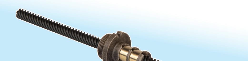
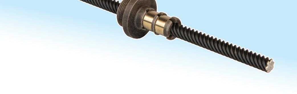
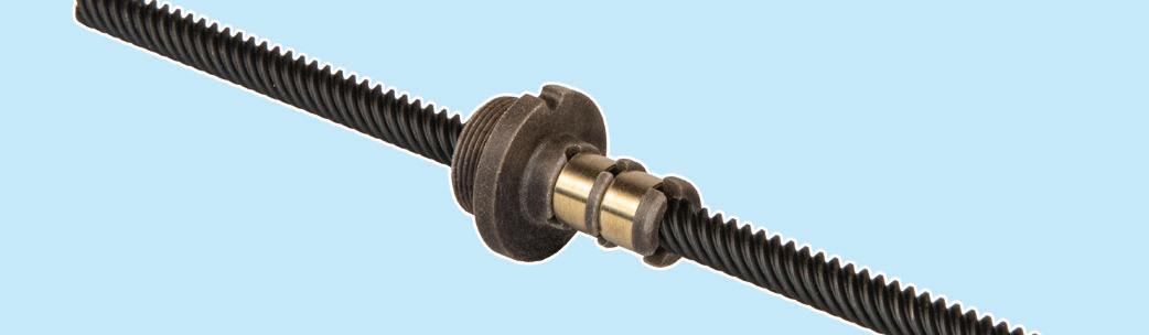


Our miniature ball screw assemblies combine fine leads with small screw diameters, and utilize a compact internal ball return system to yield high precision linear motion for a range of small-scale applications. In addition, our ball screws are precision-rolled, making them a critical asset to laboratory machines, medical devices, and mechatronic applications.

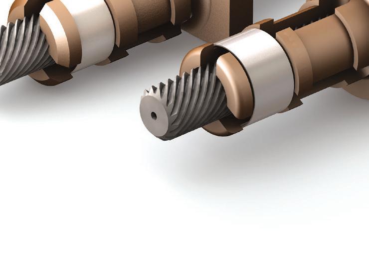
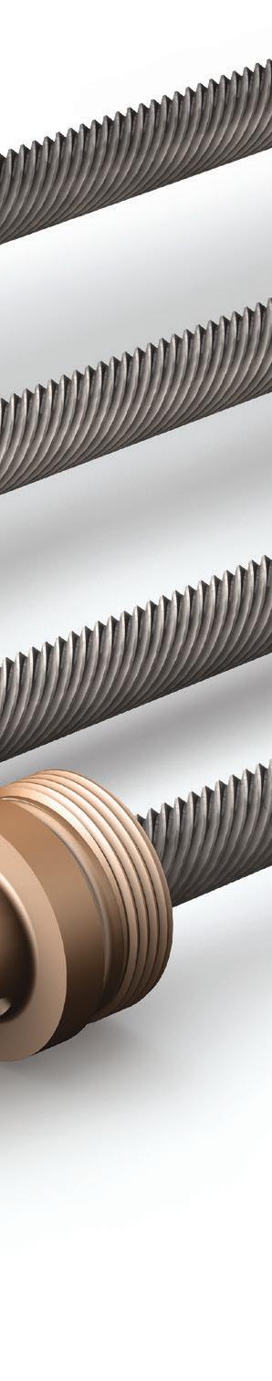
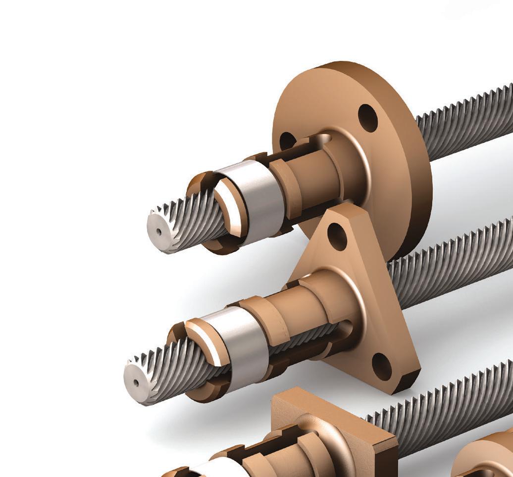

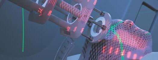
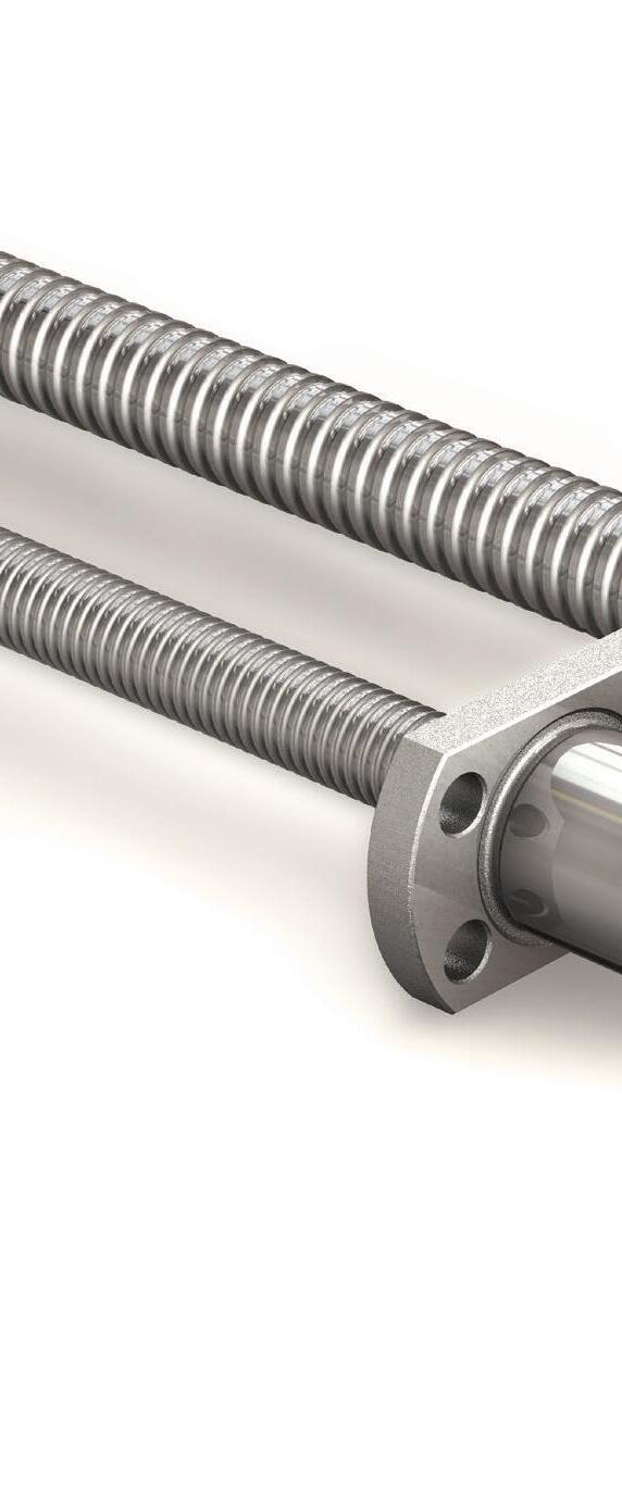
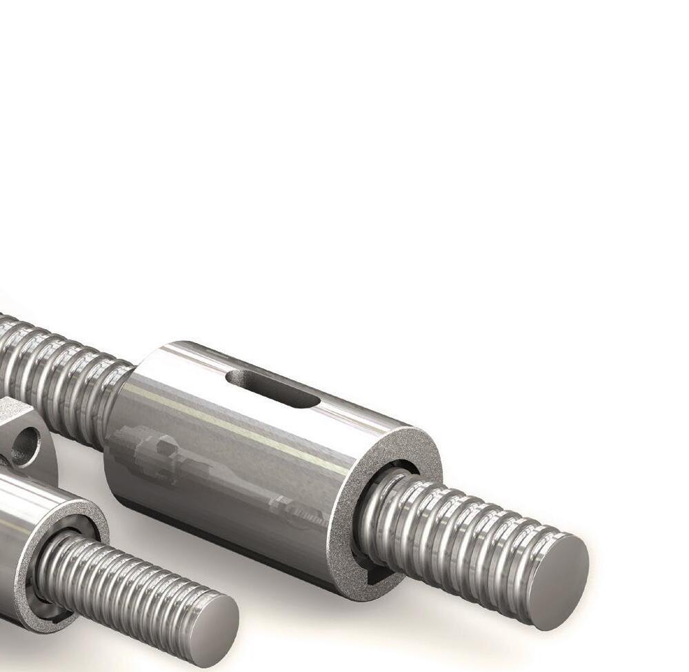

Committed to Made in the USA, PBC Linear provides high quality lead screws and ball screws in a timely manner to keep your production rolling. Request a FREE product sample at: bit.ly/leadscrewDW2023