

Table of Contents
Act
Act
Act
Iterations 84
Section Iterations 89
90
Pneumatic Airform 90
Earth 92
Curtain Wall Diagrid System 94
Workflow 96
Element Analysis 98
100
102
Site
104
105
106
107
Foreward
Caisson. The term in Architecture refers to a chamber, atrium or box, and in the field of engineering refers to an underground structure that withholds water, mud, and landscape from an internal space. This term embodies the notion of Studio 20.
Studio 20 has been an incredible opportunity at the Melbourne School of Design. The studio brief was to design a winery, using techniques and ideas explored during the first four weeks of the studio, as will be explored through the gridshell and case study exercises. These exercises explored various “form resistant structures”, whether that be a timber gridshell, reinforced concrete pneumatic shell or steel and glass shell.
Through the case study, Hao Yan and myself explored Fiera di Milano, a steel and glass shell structure over an exhibition centre. This precedent was a key inspiration for the initial concept development of our winery, however this changed with a strong concept, another key factor of the studio.
Eventually, our design evolved into a structure more incorporating the landscape and creating an experience within. Our conept was to create an immersive journey within the landscape, guided by lights and shadows, creating a sense of exploration through open and enclosed spaces.
The final design embodied this concept. Having a strong concept was paramount to a successful design, guiding the remainder of the semester allowing us to create a design we were proud to call our own. Enjoy your stay.
Elastic Gridshell Exploration
Part 1: Precedents
There are a number of takeaways from the precedent study conducted in order to understand how an elastic gridshell can be successful. A key aspect is trhe bracing, with clear bracing always around the entrance. This allows for a clear entrance and minimising outward forces from the gridshell. Furthermore, the structure itself shall be braced at continuous centres through the form.

There must also be points of anchorage on the ground, transferring the load and minimising outward forces. Many precedents use concrete anchor points where the form makes connection to the ground, withholding the elastic potential energy in the shell. The bracing itself is generally twice the with of the conventional gridshell spacing, through the centre of each diagrid panel.
The gridshell may include voids, however these must be braced similarly to any entrances on the form.
The following precedents are examples of elastic gridshell architecture, being the Japan Pavillion by Shigeru Ban Architects, the Mannheim Multihalle by Frei Otto and Acts on Tracts by the Institute of Advanced Architecture in Catalonia, Spain. Acts on tracts is noted for its unique bracing system attached to anchor points, which will be benificial for the final design.


 Mannheim Multihalle, Frei Otto
Image: Daniel Lukac
Acts on Tracks, Institute of Advanced Architecture
Japan Pavillion, Shigeru Ban
Image: Roland Halbe
Elastic Gridshell Exploration

2: Form Exploration with Paper
The next step was to use physical form finding with paper to create a gridshell form that could be developed into more realised ideas through mesh and digitisation. The assigned form of a cafe was explored through various abstracted forms, such as a croissant, espresso machine and latte art.

While this approach may be seen as cute or superficial, it was incredibly benificial as a starting point to creating an ideal form.
The abstracted espresso drip created two voids that allowed for unconventional folding points in the form. Along with this, the voids allowed for interesting light play when folded with double curvature.


Mindmap
The process of the espresso machine form began with researching images of drip. this was then sketched onto paper, with this form then segmented and cut out, with the decision to use the negative space of the espresso drip rather than the espresso drip itself, creating the two voids outlined previously. This cut out form with grid paper allowed for increased light play and curvature.


Elastic Gridshell Exploration

2: Form
with
exploration with paper resulted in four different forms, all creating unique space with unique light.
top of the
outlined on page 4, I was inspired by Melbournes laneways, that use an enclosed space to have a lively and vibrant cafe space. The brief required the gridshell to have a point of contact to a wall, with all of the iterations having connection to two walls rather than one.


result of this was spaces that resulted in less comfortable circulation and perhaps an over-enclosed space. As this design progressed, we would see spaces that only connected to a single wall that had free-flowing circulation through the space.


Elastic Gridshell Exploration
3: Chicken Wire Mesh Exploration

The design then went though further refinement and realisation through chicken wire, simulating the mesh form of an elastic gridshell. After various initial failed attempts with the original form, the shape had to be adapted to remove aspects of the void. This was due to over bending from the wire that disallowed both sinclastic and anticlastic curvature, with the form collapsing upon trying to achieve this. As a result, only the droplets from the initial form had been retained, however this was the key aspect of the void light play that I had intended to include.


In order to come to a final form, the most successful aspects of each group member’s design was implimented into one final form. The voids from my form, the bending moments from Christopher’s form and the segments of Afrah’s form were combined into one final gridshell, as seen below.


Elastic Gridshell Exploration

Part 4: Form-Finding and Analysis
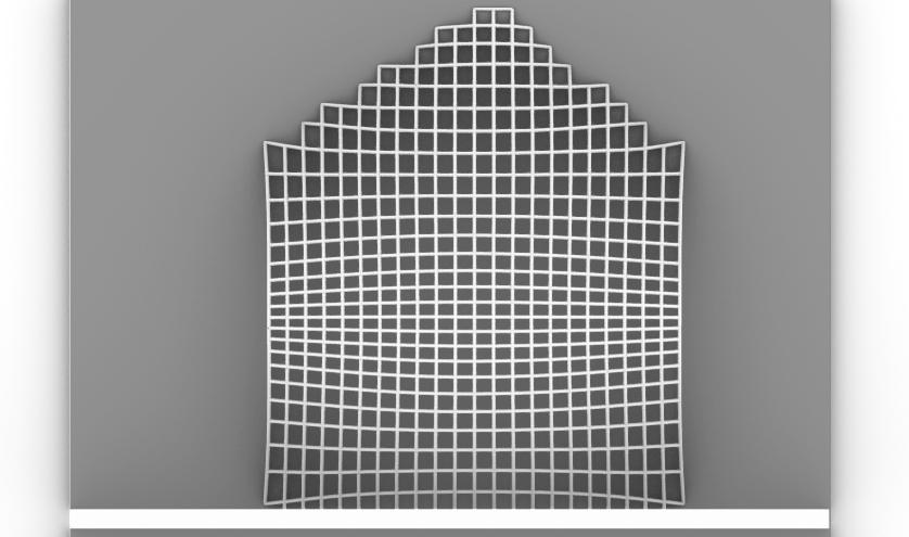
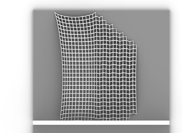
The next step was digital gridshell form-finding through a program called Grasshopper, a visual scripting software for CAD, allowing for parametric modelling. Through a plug-in for Grasshopper called Kangaroo, gridshell forms can be simulated from base shapes, calculating the height and bending moments of a physical elastic gridshell.
The selected forms for this stage were a continuation of the forms created from the initial espresso form. The edges became more rigid, and the shape became more angular, allowing for better connections to the surface. Some iterations still used the void form, with this being my preffered iteration from this step.




Elastic Gridshell Exploration

Part 5: Final Physical Model
The final design was a result of further realisation and adaption of the previous models. The model itself was created in a “T” shape, a result of cutting and changing the previous forms. It still retains similarities to previous designs such as the previous kangaroo models with the overall layout, however accessibility of the cafe had to be considered as well as connection points.
A key aspect taken from the precedents was the edge beams along the connection points of the gridshell. These serve as seating for the cafe as well as structural supports for the gridshell, as well as edge bracing providing further support.
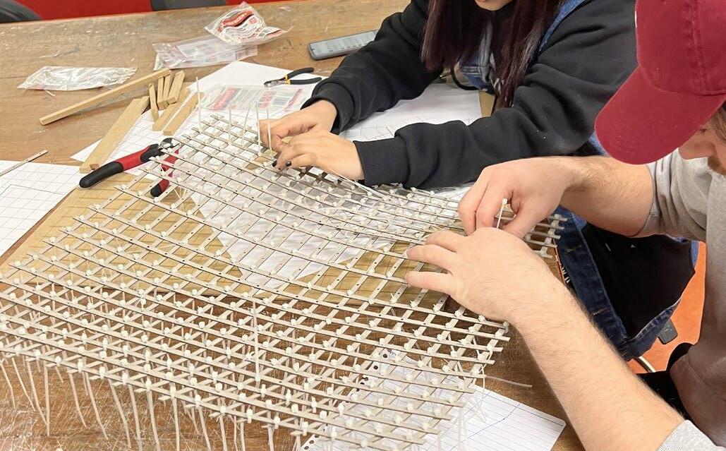


 Formation of Gridshell with cable ties
Pneumatic Shell Exploration
Part 1: Form Finding
The next step in the design journey was exploring Pneumatic shells. Pneumatic form finding is a method of using compressed air through a membrane to create form, creating space from the path travelled by the air.

My assigned brief was a “stage” design, with various considerations nessesary for this to be successful. I intended on having two different spaces within my stage, a backstage area, seating, and the stage itself being the bridging point between these spaces. Both of my base forms engaged with this, forming two “bow-tie” spaces with the stage being the pinching point. These forms, as seen on page 17, were laser cut on MDF and then formed with the Vacuum Forming machine to inflate plastic through the cutout form.
The resulting forms successfully fit the brief of a stage, however then had to be analysed in order to understand the realism of such a form.


Pneumatic Shell Exploration

of
must either be

>
Case Study: Fiera Milano
Part 1: Precedent Journal
Fiera Milano is an unconventional grid shell situated in Milan, Italy. It is a perfect case study for the exploration of gridshell structures due to the approach of several different construction methods to realise the design. The gridshell is consists of a raised peak (Logo) and several full and half valleys, referred to as volcanos and half volcanos, connected through flat quadrangular meshes that span approximately 1300 meters.
The construction of the flat portions of Fiera Milano are constructed from 240mm steel bars, connected through four-pronged nodes, resulting in a quadrangular grid. These nodes are supported by “tree columns” at intervals of 16.2 meters longitudinally and 13.5 meters transversally. The tree nodes expand out to 4 outward branches, supporting 4 nodes.
 Photograph of Fiera Milano Full volcano
Fiera Milano Full Volcano
Selected portion of Fiera Milano segmented for modelling, Schlaich et al, 2005.


 Plan view of Fiera Milano Triangular subdivisions, Schlaich et al, 2005.
Fiera Milano Full Volcano Image Credit: Studio Fuksas
Fiera Milano Half Volcano Image Credit: Studio Fuksas
The half volcanos are constructed alternatively to allow for the unconventional angles required to realise the concept. The design is far too warped to be able to support quad mesh, so the mesh becomes triangulated. The result of this is the addition of members that run diagonal to the quadrangular meshes longitudinally. In addition to this, transverse diagonal members are added to each quad mesh, making connection to the ground.
The full volcanoes become increasingly complicated, with the addition of spiralling bars. The result of this extra member is the forced introduction of a 5-pronged node, creating pentagonal mesh at these intersections in order to allow for seamless mesh. Bars arranged in a radial pattern subdivide and triangulate this mesh for fluidity.
Pentagonal Mesh


Case Study: Fiera Milano

Part 2: Initial Digital Model -
The initial model was created on Rhinoceros 7, a digital design software. The form was designed using a method called SubD, which subdivides forms and averages the curvature between subdivisions, allowing for smooth and pliable curvature in a form.
This approach was then referenced into Grasshopper, which created the members specified in the research stage, including the increased subdivisions within the volcano and half volcano forms. This however proved incredibly difficult to achive inside the volcanoes themselves, due to projection problems in the form.
The result of this was subdivisions that were far too long, with real life subdivisions in the Fiera Milano never exceeding 3 metres. Many of these subdivisions were upwards of 5 meters.
Part 2: Initial Digital Model


The initial model was created on CAD Porgram Rhinoceros 7, created through SubD, allowing for forms to fluidly be transformed through subdivisions. We were new to this tool, resulting in geometry in the volcanos and half volcanos that did not follow the plan outlined in the reference document. The rest of the form, being the vela-roof and the platforms between were generated well from SubD, with touchups in grasshopper to formulate the bars and the panels within the roof. The International Journal of Space Structures was paramount to recreating this design, with Schlaich Schober’s writings indicating how intricate aspects of the Fiera Milano were constructed. The curvature of the volcano was quite unique, resulting in difficult to replicate triangulation.


Case Study: Fiera Milano
3: Final Digital Model
After the inital analysis and feedback session, it was clear that the geometry of the volcano and half volcano had to be increasingly realistic, especially going forward into fabrication.
After days of deliberation, it was found that the method of creating the half volcano outlined in the Schlaich and Schober’s file was not the most efficient method of finding the curve geometry. Rather, the only way to make it work was to add the subdivisions directly in Rhinoceros, creating more geometry subdivisions, rather then extending the default amount of subdivisions in the half volcano. This was also efficient in the full fulcano, The document states that the helix form is key, thus by adding a helix subdivision on the SubD, the geometry properly generated.


While some subdivisions generated horizontally rather than vertically, these could be swapped and the geometry could properly form.


Case Study: Fiera Milano
Part 5: Physical Model Creation
The final physical model of the Fiera Milano was created from a combination of 1mm mountboard, along with 3D printed sections. The inital step was to segment the sections that would be laser cut, and segment the sections that were to be 3D printed.

The next step was to run a script that measured the intersections between the diagonal curves in the digital model, which then generated notches in the linework for laser cut fabrication.
Spaces that were not laser cut were sent to the 3D printers, which were the full volcano, half volcano and the trees that were to hold the structure up.
Case Study: Fiera Milano
Part 5: Physical Model Creation
The strips were then sent to the laser cutters in order to be assembled. The X and Y axis of strips were separated out and placed in their nessesary order, however this came with great difficulty to complete successfully.


Eventually, the laser cut sections of the Vela Roof were assembled, with diagonal bracing being required to reduce bending in the members. The bracing profiles had to be separately fabricated, and placed alongside the voids for the 3D printed volcanos. The notches were created through parametrically calculating the intersection of bars, creating notches depending on the thickness of material


strips
Printing of volcano structures
cut construction
bracing
Fiera Milano: Final Model

Finally, the model was braced externally, supporting the form from both lateral and transverse forces. By gluing each intersection between the bracing and the vela-roof, each strip was glued to the edge beam (bracing) thus supported. The form was then spray painted white for consistency, then finally, the 3D printed half volcano and full volcano could be inserted into the structure.


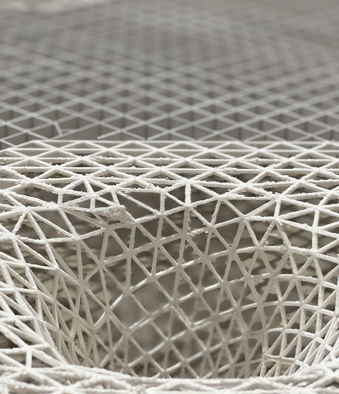

 Plan view of Fiera Milano Model
Elevation view of Fiera Milano model
Act II: Design Development
The next step was to begin our own winery design. Naturally, the first step was to review precedents of wineries that have qualities that we aimed to embody in our own design. These features were largely incorporation into the landscape, responsible vitaculture and land use and unconventional forms. Many old-world wineries tend to be rather conservative in their wineries, however these precedents reject that notion. We aspired to be bold in our designs like these unconventional old-world wineries.
Based on a site visit, basic sketch designs and spacial massing were created, with a series of conceptual digital models and plans created from this exploration and precedent study.
Precedent Study
Chateau Cheval Blanc
Christian De Portzamparc Bordeaux, France
Grape Varietals grown:
Cabernet Franc
Merlot
Cabernet Sauvingon
Malbec
A number of precedents were studied to identify successful aspects of wineries. One of the key aspects of the brief was to incorporate a form-resistant structure, like the gridshells explored in previous weeks. While not all precedents directly engage with this idea, the Chateu Cheval Blanc in the Bordeaux reigion perfectly encapsulates this idea, with a sweeping roof creating an excellent relationship between the form and the ground.


Precedent Study
Shilda Winery X-Architecture Studio Kakheti, Georgia
Grape Varietals grown: 20+
The Shilda Winery by X-Architecture Studio encapsulates how a shell can be extruded from the ground. The curvature of the form allows for light to penetrate through the southern face of the building, opening up to a space that still respects internal layout.


Precedent Study
Antinori Del Chianti Classico
Marco Casamonti, Archea Associati Chianti, Italy
Grape Varietals grown: Sangiovese Cabernet Franc Cabernet Sauvingon
The Antinori Del Chianti Classico, in the Chianti wine region (Chianti Classico, to be exact), is particularly noteworthy for the relationship with the ground plane. Situated on a hill like the Denton Site, the way the winery has a symbiotic relationship with the hill, as seen on the images capsured by Pietro Savorelli and Leonardo Finotti. Furthermore, the site plays with light in a phemonological manner, which increases user experience within the site.
 > Perspective of Antinori Winery, Pietro Savorelli, Leonardo Finotti

 ^
Internal Experiential Image, Pietro Savorelli, Leonardo Finotti
^ Southern Elevation, Pietro Savorelli, Leonardo Finotti
^
Internal Experiential Image, Pietro Savorelli, Leonardo Finotti
^ Southern Elevation, Pietro Savorelli, Leonardo Finotti
Denton Hill Winery

Part 1: Site Visit
The visit to site on the 29th of August presented a number of opportunities and challenges to approach while on site. An initial observation was the visibility of the Denton house on the site, meaning the design would have to both incorporate the view of the Denton house while still respecting the internal privacy of the house. Another observation was the incredible slope on site. It would become crucial to use this slope to an advantage and incorporate the design into the slope, while not infringing on the vines already planted on the slope.
> Northern entrance to the Denton site

Denton Hill Winery
2: Site Analysis
Denton Hill Winery
Part 3: Sketch Design Concepts
The next challenge was to come up with initial ideas of form through sketching. Through the precedent study, certain aspects of each precedent were identified. These qualities were then sketched, in an effort to find a final form that embodied the best qualities of all three selected precedents. The key quality from all precedents to follow was an interaction with the ground plane, with all of the forms cutting into the side of the Denton Hill.


Form incorporating aspects of Chateu Cheval Blanc
Form incorporating aspects of Antinori Del Chianti Classico
Form incorporating aspects of Shilda Winery
Denton Hill Winery

3: Sketch Design Concepts


Design Development
Based on the brief, the next step was to analyse the size of
for the
The required
were a wine production facility, as well as a cellar for storage purposes, making up the production aspect of the program. The hospitality aspect of the program consisted of a cellar door for tasting and small meals, along with a resturant for larger meals. Additionally, the program consists of four suites.
Design Development
Part 2: Initial Plans
The initial plan created by the spacial analysis allowed for continuous flow through the site, however was all situated on a flat plane and didn’t incorporate the site well enough. Additionally, the suites and production spaces were too far removed from the form itself.


Design Development
Part 2: Initial Plans
As seen in the below section, the cellar space was situated directly below the cellar door space, however this still seemed too cramped so the spaces were to increase in size. Furthermore, the space had to have more space to allow for additional programs such as bathrooms, kitchens and plant rooms.
> Initial axonometric section featuring cellar space

Design Development
Part 3: Revised Plans
The revised plan adapted to the problems that arose from the initial plans. The new program allowed for bathrooms, being male, female and ambulant, as well as a larger, dedicated kitchen space. The production space, offset into the hill, featured a number of dedicated spaces for the program, as outlined in the plan. Circulation between the production space and the hospitality space was done primarily through the cellar, as a bridging between the two.
>
Initial Sub Divided gridshell roof.


Design Development
Part 4: Draped Roof Exploration
The initial approach to fulfilling the brief of a form resistant structure was through a “draped” form, using SubD for Rhinoceros 7, a CAD software that subdivides a surface and calculates the curves between subdivisions. This approach was resemblant of the Fiera di Milano case study, adapted for this design.
While this form did include all of the brief under the same roof, it didn’t encourage the connectivity that was intended between spaces and potentially over-enclosed the space.

Axonometric Section of draped roof


-
Plan

Final Concept Design


Final Site Plan


Final Concept Design
Part 1: Cellar Design
The final concept design stemmed from a further adaption of the program outlined above, with an addition of a gallery space on an upper level. The gallery, doubling as a mezzanine space encourages a more continuous circulation through the space, with a path not having a clear, designated end, rather drawing the individual through the space. Eventually, the user re-emerges in the cellar door space to continue circulation through the remainder of the space.

The Plan as seen on the following page represents the cellar space offset into the ground. The curved form in the cellar pays homage to traditional “barrell vault” cellar designs, while still maintaining a contemporary relationship with the above space. The cellar features Oak Barrells for Ageing, as well as stainless steel vats for un-oaked wines. Additionally, the space features a number of Cuvees for sparkling wine production.
>
Hero shot of cellar space

Final Concept Design
Part 2: Main Hospitality Centre Design

The adapted plan of the main hospitality centre maintains an open plan approach to the space. As seen on the following plan, the space encourages an elliptical circulation through the space through the use of the voids in the space. Furthermore, this circulation draws resturant patrons away from the private suite areas, with no natural conclusion to the space.
The main “Barrell Void” provides views into the cellar space underneath, while being a natural barrier between the cellar door and the restaurant. This draws people around and through the space as they get views into the cellar, as well as views out to the Yarra Valley.
Denton’s Production space is featured at the same elevation as the hospitality centre, however offset into the hill to the south of the space. The access between the two spaces is through the cellar, as a bridging space.
Plan view of Hospitality Centre and Production facility, 1:500

Final Concept Design
Part 3: Upper Gallery/Museum Space
The Final Addition to the design is an upper gallery and museum space for exhibition use. As an open mezzanine space, it provides a dynamic relationship between the restaurant space and the cellar. This encourages circulation through all three spaces by people drawn to site for different reasons, having a direct visual connection. The space also provides framed views to the denton house through a glass skylight, drawing people through the space and engulfing them in the Yarra Valley.


Final Concept Design
Part 4: What comes next?
The next step is to incorporate more form-resistant structures into the form, creating a more immersive experience within the space. The goal is to have cleaner circulation between spaces on multiple levels, and have the spaces more complimentary to the surrounding environment.
While the space does incorporate form resistant structures through the pneumatic cellar and the bridging view glass spaces between the cellar and the remainder of the form, these can become clearer and more defined.
Section through cellar, hospitality and gallery spaces (Hao Yan)


Act III: Span and Space
As the approach to design became increasingly realised and literal, more consideration to the design as inhabitable space had to be considered. A strong concept was developed, expanding our design ideas. Our concept centred around a journey through the landscape, guided by light and voids underneath the land. We aimed to create an immersive experience exploring open and enclosed spaces, evoking feelings of adventure and exploration. This concept was further explored through five developed plans and five developed sections, that best represented this concept and the experiences we wanted to evoke. A series of detail iterations were created to further realise the concept.
Plan Iterations
Iteration #1
The approach of the initial plan iteration was to better encapsulate the idea of the cave. Our refined concept was “A journey of immersion and exploration through cave-like forms, creating feelings of being within the earth”. In the first iteration, this was encapsulated through following a series of voids and skylights through the space. The voids guide the user through light, drawing the user through the space as they follow the light.

Plan Iterations
Iteration #2
The next iteration built on the first by further encouraging feelings of exploration through the spaces. By making the circulation less linear, the user is encouraged to become immersed in the space and explore. The space experiments more with open versus enclosed spaces, immersing the user in the journey through caves that we wanted to achieve. The idea of the voids being a central guiding aspect is still paramount to the iteration. The iteration further experiments with heavy versus light massing, rather than homogenous wall thicknesses, creating a cavelike experience.
> Initial concept sketch of Iteration 2

Plan Iterations

Iteration #3
The third iteration improves further upon the second iteration by having a more circular flow. The aspects of immersion are still clear by having the user explore the space through the voids, however the spaces are slightly more separated and distinct, with each new space bringing a new immersed experience.
Plan Iterations

Iteration #4
Iteration 4 takes the idea of the cave through a new approach, further experimenting with enclosed and open space. By creating a “pinch” effect on the centre of the space, the users are squeezed through spaces, reflecting crevasses found in a cave. On the other side of the pinch is an open chamber with another void, drawing light into the space, with the voids again providing the key indication of the spaces to explore next.
Plan Iterations

Iteration #5
The final iteration was the plan that was chosen to become finalised. The iteration focusses on open vs enclosed space to create immersion, creating a series of cave chambers that are discovered through multiple pinches in the form. The circulation is far less linear than the other iterations, with the journey of exploration truly immersing the user in the space, having the freedom to choose the next space they want to discover.
> Initial concept sketch of IterationSection Iterations

Concurrently, sections were being developed following the same concept in order for the spaces in plan in section to reflect each other. The final selected section can be seen, which informed the following plans and sections.

Section Iterations


The final sections of the space were then created, from a conglomeration of Iteration 5, and a new digital model from Iteration 5 to infrom the new section. It was paramount to the design that not all spaces take place on a single level, with the journey through the site needing to be on the Z axis as well as X and Y, to truly immerse the user in the experience of the cave. The voids as a central guiding feature are still paramount in the sections, creating natural light in an otherwise dark space.
 > Hao’s visual representation of different spaces in section (Hao Yan)
Final


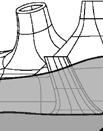


Detailed Design System 1: Pneumatic Airform
The initial iteration of a detailed design features a pneumatic airform structure. Prefabricated airforms are created from a composite tarpaulin, fabricated off site to the size of a desired gridshell. High pressure fans are installed on site, with the prefabricated airform being hooked into an in-situ concrete slab at nessesary intervals.
The high pressure fans inflate the airform, with an initial concrete layer being applied to the exterior of the airform. Reinforcements are then placed within the concrete, with a finishing layer of concrete then applied to the form. The airform is then removed, creating an interior space to be sprayed with Polyeuthane foam and an interior finish.
In this instance, with the addition of the void structures, extra reinforcements have been placed on the exterior with a retaining wall to support the void.
SKIRTING AND CABLE TRAY TATE RAISED FLOOR SYSTEM TATE PEDESTAL BASKET
AIRFORM ANCHOR BOLTED TO SLAB
REINFORCEMENTS BOLTED TO SLAB IN-SITU SLAB TO ENGINEER’S SPEC
RC AIRFORM SHELL GROUND CONNECTION DETAIL
SHOTCRETE, 20mm, FINISHING LAYER PREFABRICATED AIRFORM POLYEUTHANE FOAM REINFORCEMENT TO ENGINEER’S SPEC IN-SITU CONCRETE APPLIED TO FOAM DISPLACED EARTH MOVED AROUND SHELL
CHAMBER
PRECAST RETAINING WALL TO ENGINEER’S SPEC REINFORCEMENTS BOLTED TO RETAINING WALL REINFORCEMENTS WELDED TO REBAR LAYER IN SHELL
EXCAVATED EARTH REPLACED
STRUCTURE
SHOTCRETE, 20mm, FINISHING LAYER PREFABRICATED AIRFORM POLYEUTHANE FOAM REINFORCEMENT TO ENGINEER’S SPEC IN-SITU CONCRETE APPLIED TO FOAM REINFORCEMENT CONTINUES TO SLAB
AIRFORM COMBINATION POINT
TATE RAISED FLOOR SYSTEM
POINT, BOLTED TO SLAB
Detailed Design System 2: Rammed Earth
The second detail iteration features a rammed earth design. The structure is created using rammed earth blocks, creating a dome. As extra reinforcements, a reinforced concrete beam encircles each dome, which also serves as reinforcements for the meeting point of two separate domes.
In order to reinforce the void, an additional steel beam encircles the base of each void structure, bolted into the blocks. The void rammmed earth blocks are then built atop the beam, with a finishing layer then applied to the exterior of the structure before returning the displaced soil to the site.
LOW-E DOUBLE GLAZING WITH ARGON AIR GAP
100X150 RAMMED EARTH BLOCKS
BLOCKS FIXED TO BRACING STRUCTURE
FINISHING MORTAR LAYER
DAMP PROOF MEMBRANE
DOME FROM RAMMED EARTH BLOCKS, FABRICATED IN-SITU
STEEL CIRCULAR BRACING, BOLTED TO EARTH BLOCKS
EARTH FINISHING LAYER
DAMP PROOF MEMBRANE
EXCAVATED EARTH REPLACED POST-COMPLETION
DOME FROM RAMMED EARTH BLOCKS, FABRICATED IN-SITU
LAYER OF LIGHTWEIGHT COMPRESSED EARTH
DAMP PROOF MEMBRANE
FINISHING MORTAR LAYER
DRAINAGE GUTTER
400MM REINFORCED CONCRETE TRANSFER BEAM
90MM INTERNAL DOWNPIPE
100X150 RAMMED EARTH BLOCKS
TATE RAISED FLOOR SYSTEM
CONCRETE SLAB TO ENGINEER’S SPEC
DRAINAGE TO FILTRATION SYSTEM
Detailed Design System 3: Steel Curtain Wall Diagrid System
The third detail iteration features a steel and glass diagrid system, with each triangle resembling a unitised curtain wall system. The form is constructed using 100mm vertical steel bars, and 90mm transverse bars. Each transverse bar is bolted to 120mm steel node. Each vertical steel bar is welded to the node for additional vertical stability.
The form is then clad to create the cave-like effect within the space, using concrete cladding connected through stack joints that are bolted to the mullions. Where voids are nessesary, the stack joints connect glass panels. The exterior of the form is then clad with concrete and the displaced earth is returned to site.
STEEL AND GLASS SHELL CURTAIN WALL DETAIL
STEEL AND GLASS SHELL CURTAIN WALL DETAIL
IN SITU CONCRETE REINFORCED TO STEEL SHELL
100MM RADIAL BARS, WELDED TO NODE
90MM BATT INSULATION
IN SITU CONCRETE REINFORCED 100MM RADIAL BARS, WELDED
90MM CURTAIN WALL MULLION, BOLTED TO STACK JOINT 12MM PLASTERBOARD
90MM BATT INSULATION 90MM CURTAIN WALL MULLION, 12MM PLASTERBOARD
CABLE TRAY SKIRTING
CABLE TRAY SKIRTING
CURTAIN WALL STACK JOINT, BOLTED TO NODE
BASE STRUCTURE NODE, BOLTED TO SLAB
TATE RAISED FLOOR SYSTEM
CURTAIN WALL STACK JOINT,
TATE RAISED FLOOR SYSTEM
CONCRETE SLAB TO ENGINEER’S SPECIFICATION
BASE STRUCTURE NODE, BOLTED CONCRETE SLAB TO ENGINEER’S
STEEL AND GLASS SHELL GROUND CONNECTION DETAIL 1:20
100MM RADIAL BARS, WELDED TO HEAVY GAGUE STEEL NODE
90MM TRANSVERSE BARS, BOLTED TO NODE SOCKET REQUIRED ANGLE
20MM BOLTS
10MM NODE SOCKET, WELDED TO NODE
WELDED CONNECTION
100MM RADIAL BARS, WELDED TO HEAVY GAGUE STEEL NODE
90MM TRANSVERSE BARS, BOLTED TO NODE SOCKET AT REQUIRED ANGLE
20MM BOLTS
10MM NODE SOCKET, WELDED TO NODE
WELDED CONNECTION
100MM RADIAL BARS, WELDED TO NODE
90MM TRANSVERSE BARS, SPAN DEPENDENT ON ANGLE OF PLACEMENT
AREA DEPENDENT ON CORRESPONDING SPANS AND ANGLES
120MM BASE NODE, BOLTED TO SLAB
CONCRETE SLAB TO ENGINEER’S SPEC
100MM RADIAL BARS, WELDED TO NODE 90MM TRANSVERSE BARS, SPAN DEPENDENT ON ANGLE OF PLACEMENT
AREA DEPENDENT ON CORRESPONDING SPANS AND ANGLES
120MM BASE NODE, BOLTED TO SLAB
CONCRETE SLAB TO ENGINEER’S SPEC
STEEL AND GLASS SHELL GROUND CONNECTION DETAIL 1:20
STEEL AND GLASS SHELL NODE DETAIL 1:2
STEEL AND GLASS SHELL NODE DETAIL 1:2
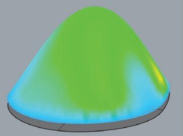
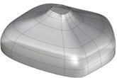
Digital Workflow Forms for Analysis
the paramaterisation
The forms use two kinds of digital
a simple pneumatic form for the single
and subdivided freeform geometry for the
forms of the model. The pneumatic forms were
through form finding, while the free forms had to be optimised through a genetic algorithm and fitness
had a FEM analysis conducted. The various
forms for analysis are seen in the left figure. The
workflow can be seen on the following page.


Digital Workflow
FEM Analysis


Act IV: Final Design Proposal
Once the concept, plans and sections had been determined, it was time to refine the selected drawings and digital forms to come to a final, developed design. The final digital workflow was decided upon, with a genetic optimisation algorithm determining the best fit forms for the design.
Once this had been resolved, the final plans, sections details and renders had to be finalised. The plans were altered to allow for the optimised forms, with the sections lending themselves to this improved plan. The details were altered to allow for internal lights, insulation and waterproofing, with the final digital renders being a culmination of the above.
Final Design




Workflow

Final Design
Final Site Plan
Final Design


Final Sections
The final sections were developed from the previous sections in the span and space section. A key challenge was finding the correct section cut, finding a cut that outlined as many of the various shell forms as possible. The sections resulted as a composite of both group members inputs, with the design intent of both displaying the landscape and the shells underneath, as well as how users interact with the light and shadows within the spaces. Both horizontal and vertical circulation also had to be considered.

Final Design
Final Sections
While not a required deliverable for the project, an axonometric section was also key. By showing how the spaces directly interact with the landscape in a three-dimensional perspective, the viewer can directly interpret the relationship between the spaces underneath and the landscape above.


Final Design Detail Drawings
The shells are constructed from a number of pneumatic airforms with the structure constructed around the airform. Initially, land is excavated where the shell will be constructed, with a retaining wall being constructed on the perimeter of this land. An in-situ concrete slab is laid on site, with anchor points for the airform cast into the concrete. The prefabricated airform is then inflated, with a rebar layer and concrete being applied to the outside of the airform. The airform is then removed, with the internal spaces having a finishing layer of concrete applied. The landscape is then returned to the exterior, creating an internal open space underneath the landscape.

DAMP PROOF MEMBRANE
SKIRTING
CABLE
SHOTCRETE
PREFABRICATED AIRFORM POLYEUTHANE FOAM REINFORCEMENT TO ENGINEER’S SPEC IN-SITU CONCRETE APPLIED TO FOAM DISPLACED EARTH MOVED AROUND SHELL BATT INSULATION DAMP PROOF MEMBRANE
FINISHING SHOTCRETE LAYER
AIRFORM ANCHOR BOLTED
REINFORCEMENTS BOLTED
IN-SITU SLAB
ENGINEER’S
RC AIRFORM COMBINATION POINT
SHOTCRETE, 20mm, FINISHING LAYER PREFABRICATED AIRFORM POLYEUTHANE FOAM / SHOTCRETE COMPOSITE REINFORCEMENT TO ENGINEER’S SPEC IN-SITU CONCRETE APPLIED TO FOAM
REINFORCEMENT COMBINATION POINT, WELDED
REINFORCEMENT BOLTED TO STUD LAYER
Final Design Detail Drawings
It is nessesary that the voids are braced and created to be watertight. A steel ring is applied to the void, bracing the exterior. The ring is bolted to the concrete and the reinforcements, which links to the retaining wall on the exterior of the structure. The ring, acting as a typical cleat, allows for double glazed glass to span the void, creating additional bracing. The cleat and glass connection are hidden internally, creating a clean view for the user.
POLISHED
LAYER
BOLTED TO
GLASS
SOCKET, BOLTED TO BRACING
TO RETAINING WALL
PRECAST
DAMP
Final Design

1:25 Model
The 1:25 physical model was created to give a more intimate view of the internal spaces itself. The ampitheatre space was chosen for this model, with multiple layers of seating and a central void, as a standard representation of many of the spaces in the design. Initially, contours were extracted from the digital model at 6mm intervals, with the contours then being printed on 6mm MDF. Once these contours were constructed, the three part model allowed for a direct internal view by one side of the shell being removable from the base.


Final Design


1:100 Model
The 1:100 physical model was constructed by digitally extracting contours from the digital model at 6mm intervals. The 6mm contours were then laser cut on 6mm MDF, which then allowed assembly to take place. The model was kept as open massing to allow for viewing inside of the model to envisage the spaces and layout. The next step was to cast plaster around the model to create the landscape.


Digital
Model


Final


Glossary of Terms
Form Resistant Structure: A structure in which the form is defined by the loads beared upon it, creating form that takes shape from the material surrounding it.
Gridshell: A doubly curved structure that is constructed from a grid of material allowing synclastic and anticlastic curvature
Pre-Formed: Curvature of a shell that is determined before the erection of the form, with rigid members
Post-Formed: Curvature that is determined after the erection of the form with members that can bend and twist
Sinclastic: Form that curves toward the same side in all directions
Anticlastic: Form that curves concavely on one axis while convex on the perpendicular axis
Elastic Gridshell: A gridshell, typically constructed from timber, that is post-formed and uses elastic force to create its form
RC Shell: A gridshell like structure constructed from reinforced concrete
Pneumatic: A form created by the manipulation of compressed air on a malleable material
FEM Analysis: Finite Element Analysis. A digital analysis method that calculates loads on an object and highlights the structural performance
Rhinoceros 7: A digital 3D modelling software
Grasshopper: A plug-in for Rhinoceros allowing for improved parametric design
Parametric: Design that calculates forms within a network of numerical imputs
Kangaroo: A parametric design software for Grasshopper allowing for calculation of gridshell curvature
Karamba: FEM Analysis software
Displacement: The measurement of how successful a form is. Measures how well the structure conforms to the digital input into the software in the real world.
CAD: Computer Aided Design. Refers to digital software used to design spaces based on numerical inputs and exact dimensions.
Bibliography
Afrah, 2022. Mesh Model Sketch. [image]
Christopher Andonioff, 2022. Mesh Model Sketch. [image]
Eric Saillet and Max Botton, 2011. Chateau Cheval Blanc. [Image] Available at https://www.archdaily.com/455019/chateau-cheval-blanc-winer-agences-elizabeth-christian-de-portzamparc [Accessed 8/09/2022].
Eric Saillet and Max Botton, 2011. Chateau Cheval Blanc. [Image] Available at https://www.archdaily.com/455019/chateau-cheval-blanc-winer-agences-elizabeth-christian-de-portzamparc [Accessed 8/09/2022].
Eric Saillet and Max Botton, 2011. Chateau Cheval Blanc. [Image] Available at https://www.archdaily.com/455019/chateau-cheval-blanc-winer-agences-elizabeth-christian-de-portzamparc [Accessed 8/09/2022].
Frei Otto, 1975. Mannheim Multihalle [image] Available at: https://www.designboom.com/architecture/frei-otto-a-life-of-research-construction-and-inspiration-detail-book-report-06-02-2015/ [Accessed 25th July 2022].
Hao Yan, 2022. Plans [image]
Hao Yan, 2022. Final Renders [image]
Hao Yan, 2022. Model Renders [image]
Hao Yan, 2022. Progression Diagram. [image]
Hao Yan, 2022. Section. [Image] [Accessed 8/09/2022].
Institute for Advanced Architecture, 2015. Acts on Tracks. [image] Available at: <https://www.iaacblog.com/programs/acts-on-tracks/> [Accessed 25 July 2022].
Michael Archviz, 2013. Shilda Winery. [Image] Available at https://www.x-architecture.co.uk/project/shilda/ [Accessed 8/09/2022].
Michael Archviz, 2013. Shilda Winery. [Image] Available at https://www.x-architecture.co.uk/project/shilda/ [Accessed 8/09/2022].
Michael Archviz, 2013. Shilda Winery. [Image] Available at https://www.x-architecture.co.uk/project/shilda/ [Accessed 8/09/2022].
Pietro Savorelli and Leonardo Finotti, 2012. Antinori Winery. [image] Available at: https://www.archdaily.com/371521/antinori-winery-archea-associati [Accessed 8/09/2022].
Pietro Savorelli and Leonardo Finotti, 2012. Antinori Winery. [image] Available at: https://www.archdaily.com/371521/antinori-winery-archea-associati [Accessed 8/09/2022
Pietro Savorelli and Leonardo Finotti, 2012. Antinori Winery. [image] Available at: https://www.archdaily.com/371521/antinori-winery-archea-associati [Accessed 8/09/2022
Schober, Schlaich. 2005. “New Trade Fair In Milan”. International Journal Of Shigeru Ban, 2002. Japan Pavillion. [image] Available at: https://clarewashington.wordpress.com/2012/12/10/shigeru-ban-building-with-paper-japan-pavilion-expo-2000/ [Accessed 25th July 2022].
Space Structures 20 (1): 1-14.


