|
| S U B M I T TA L
S E R I E S H STAN DAR D CIRCU L ATO R S
File No: 10.51 Date: march 01, 2017 Supersedes: 10.51 Date: june 03, 2015
Job: Representative: Ordered by: Engineer:
Date:
Submitted by: Date:
Contractor: Approved by:
p um p d e s i g n data Pump model:
m a x imum pum p o pe r at i n g co n d iti o n s 175 psig at 2 25°f (120 6 kPa at 107 °c)
Flange size:
No. of pumps:
Date:
Note:
Capacity:
USgpm (L/s) Head:
ft (m)
Temperature: °f (°c) Liquid:
o p t i o n a l eq u i pm e nt
Companion flanges: Included All Bronze Circulators are nsf – 372 rated
m at e r ia l s o f co n st ru c ti o n part name
h-32 to h-54 bronze fitted
h-63 to h-68 bronze fitted
h-32 to h-54 lead free bronze*
h-63 to h-68 lead free bronze*
Pump Body
Cast iron
Cast iron
Lead free bronze
Lead free bronze
Coupler
h-32 & h-41 flexible, 4-spring h-51 to h-54 flexible, spacer type
Flexible, spacer type
h-32 & h-41 flexible, 4-spring h-51 to h-54 flexible, spacer type
Flexible, spacer type
Seal: Mechanical
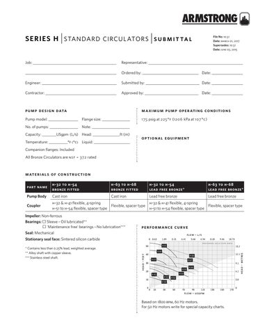
pe r fo r m a n c e cu rv e Based on 1800 rpm, 60 Hz motors. For 50 Hz motors write for special capacity charts. flow - l/s
Stationary seal face: Sintered silicon carbide
1.89
3.15
4.41
40
20
0
H68 H67
H41
H54 H66 H53
10
H51 H52 H32 30
8.20
9.46
10.73 15.2
H63
10
6.94
p r e fee r r e d selection area a
30
0
5.68
H65 H64
50
head - feet
* Contains less than 0.25% lead, weighted average. ** Alloy shaft with copper sleeve. *** Stainless steel shaft.
0 0.63
50
12.1
9.1 6.1
3.0
70
90
head - metres
Impeller: Non-ferrous Bearings: Sleeve - Oil lubricated** 'Maintenance free' bearings - No lubrication***
110
130
150
flow - usgpm
Based on 1800 rpm, 60 Hz motors. For 50 Hz motors write for special capacity charts.
170
0
Series H Standard circulators
s u bmit tal
2 model
motor † flange size (n.p.t) hp phase and volt
H32
dimensions inches (mm) a
weight
b
c
d
lbs (kg)
1
T
H32
1N
T
H32
1K
T
H41
1
T
H51
1
N
H52
1N
L
H53
1K
K
20.00 (508) 11.50 (292) 16.50 (419) 0.88 (22) 64 (29.0)
H54
2
O
20.00 (508) 11.50 (292) 16.50 (419) 0.88 (22) 71 (32.0)
H63
1K
K
H64
1K
O
H65
1K
1
H66
2
O
23.25 (591) 14.00 (356) 19.75 (502) 0.88 (22) 120 (54.0)
H67
2
1
23.25 (591) 14.00 (356) 19.75 (502) 0.88 (22) 125 (57.0)
H68
2
1K
1 phase 115 V
15.00 (381) 8.50 (216)
12.50 (318) 0.88 (22) 33 (15.0)
15.00 (381) 8.50 (216)
12.50 (318) 0.88 (22) 33 (15.0)
15.00 (381) 8.50 (216)
12.50 (318) 0.88 (22) 33 (15.0)
15.25 (387) 8.50 (216)
12.50 (318) 0.75 (19) 33 (15.0)
17.25 (438) 11.50 (292) 13.50 (343) 0.75 (19) 53 (24.0)
1 phase 115 V or 3 phase 208/230/460 V
17.25 (438) 11.50 (292) 13.50 (343) 0.88 (22) 54 (24.0)
23.00 (584) 13.50 (343) 19.75 (502) 0.88 (22) 96 (44.0)
1 phase 115/230 V or 3 phase 208/230/460 or 575 V
3 phase 208/230/460 or 575 V
23.00 (584) 13.50 (343) 19.75(502)
0.88 (22) 100 (45.0)
23.00 (584) 13.50 (343) 19.75(502)
0.88 (22) 102 (46.0)
21.75 (552) 14.00 (356) 18.25 (464) 0.88 (22) 130 (59.0)
Dimensions shown are for reference only. For exact dimensional data, contact factory. † All single phase motors are equipped with a built-in thermal overload protection. Three phase motors require external overload protection. Conduit box not supplied on ½ hp or greater.
d
c
a
b
d toronto
fig a: horizontal mounting
end view
b
k
d side view
+1 416 755 2291
buffalo +1 716 693 8813
c
a
d
birmingham +44 (0) 8444 145 145
b
manchester +44 (0) 8444 145 145
bangalore +91 (0) 80 4906 3555
k resilient mount
d
shanghai +86 21 3756 6696
são paulo +55 11 4781 5500
a r m s t r o n g f lu i d t e c h n o lo g y established 1934
d
a r m s t r o n g f lu i d t e c h n o lo g y. c o m