Infinite Bond: Rural Community Center B.Arch Thesis pg. 50
Miscellaneous: Net Zero House
Materiality
Academic pg. 60
Buffalo, NY, USA
Mumbai, India Patan, India
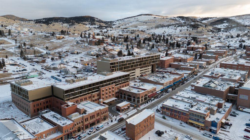
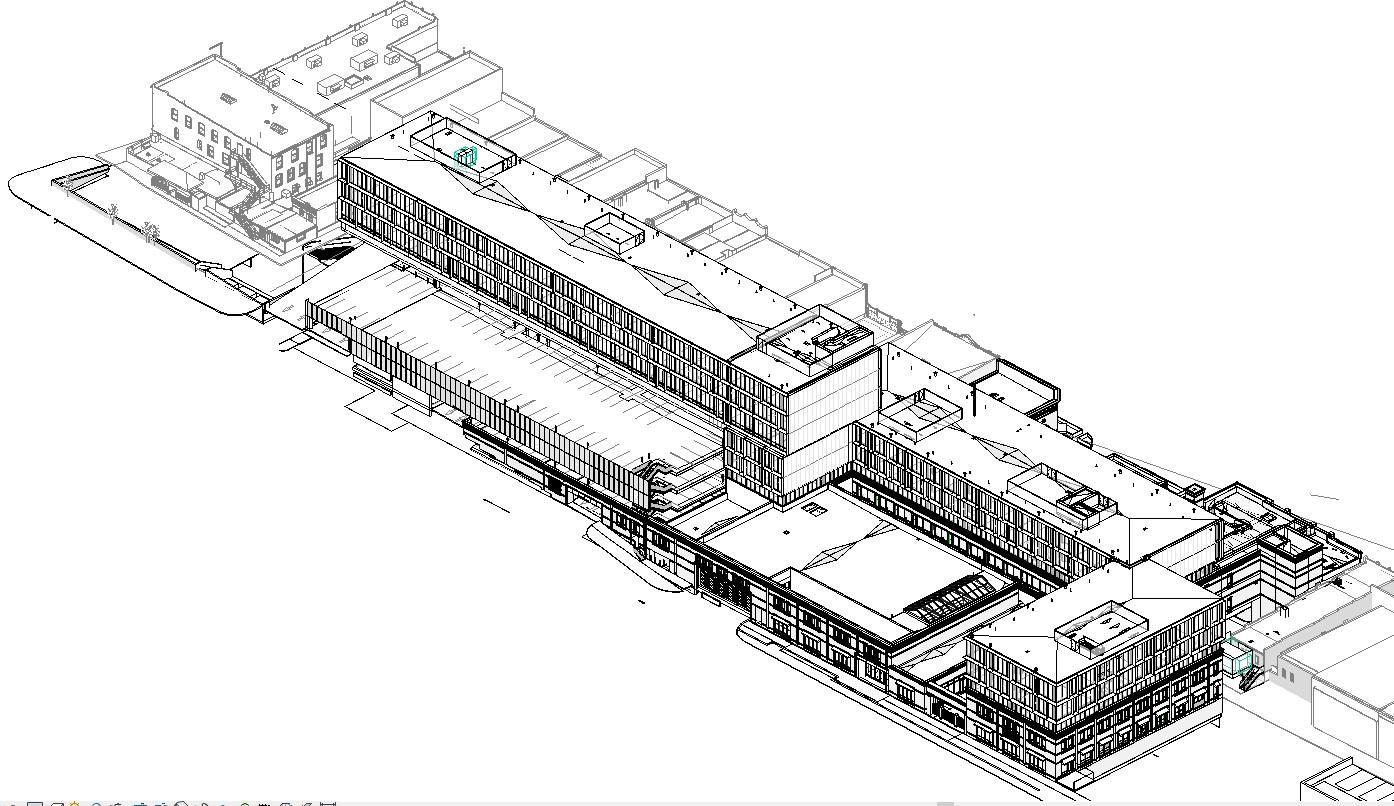
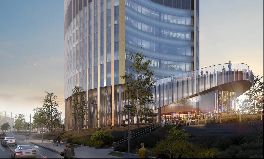
CHAMONIX HOTEL & CASINO
Cripple Creek | Colorado
2021-22 | Construction Completed
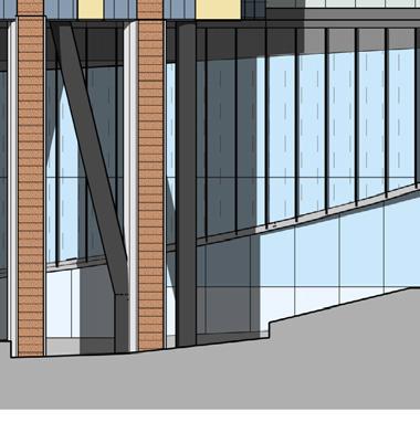
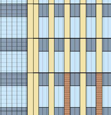
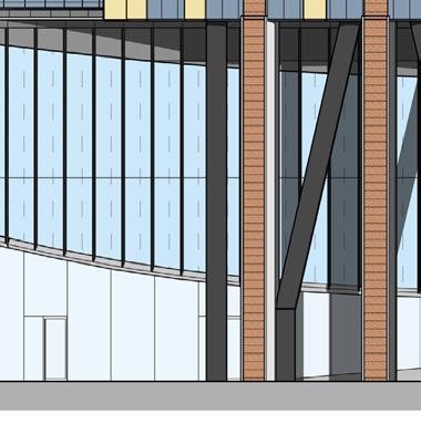
When I joined CannonDesign, this was the first project I worked on. My background in the thematic industry and expertise in building envelopes enabled me to contribute effectively to a project of this scale and complexity. As part of a collaborative team, I was actively involved in the project for approximately a year and a half, from the late Schematic Design phase through the early Construction Administration process. I assisted in developing and documenting the brick portion of the building, working closely with team members to refine design details. While the design evolved through multiple revisions, our primary focus was on incorporating thematic casino elements such as ornamental brickwork and cornice detailing, coordinating opening sizes to align with brick modules, and facilitating the transition from the brick envelope to the modern, metal-clad hotel superstructure.
Coordination Lead: Josh Behrns, Aniket Datar
Softwares: Revit, Rhino, Bluebeam
Contribution: Schematic Design to Construction Administration (Envelope Core & Shell Package)Facade Development and detailing for Brick levels
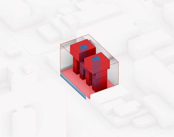
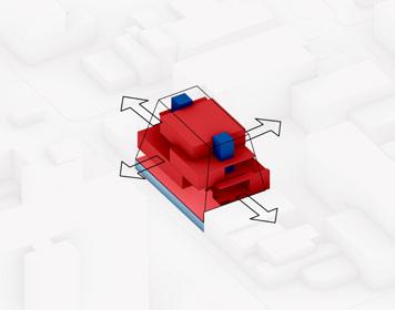
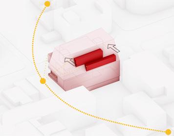
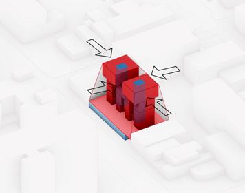
Massing Strategy
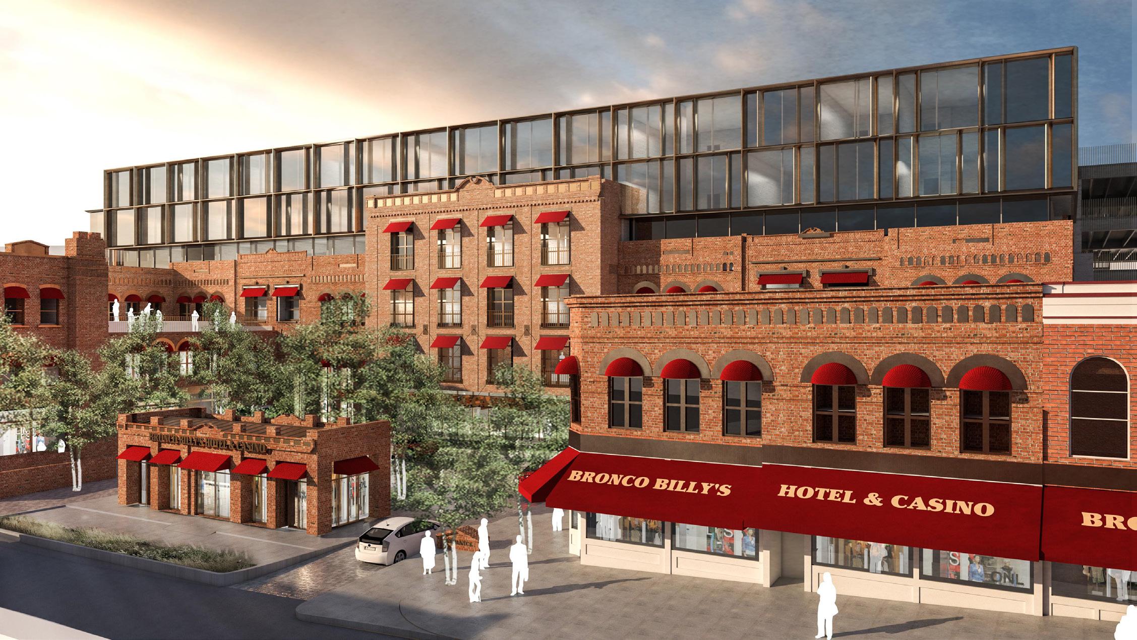
BRONCO BILLY`S CASINO
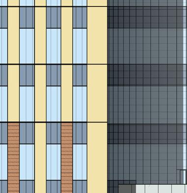
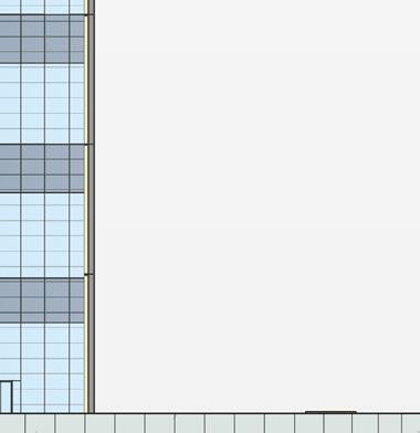
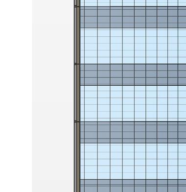
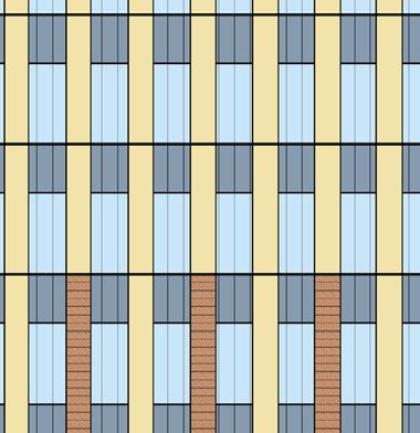
The rich urban fabric of the existing Bronco Billy’s Casino influenced the material selection, with brick chosen as the primary cladding to maintain architectural continuity. A key design challenge was preserving a consistent brick line across the exterior envelope despite the site’s steep topography. The north elevation’s Level 1 aligns with the south elevation’s Level 2 due to a significant slope, while the west-to-east contour is more gradual, allowing for a smoother transition. This elevation shift required careful design coordination to ensure visual and structural cohesion throughout the project.
Schematic
FABRIC AWNINGS, TYP.
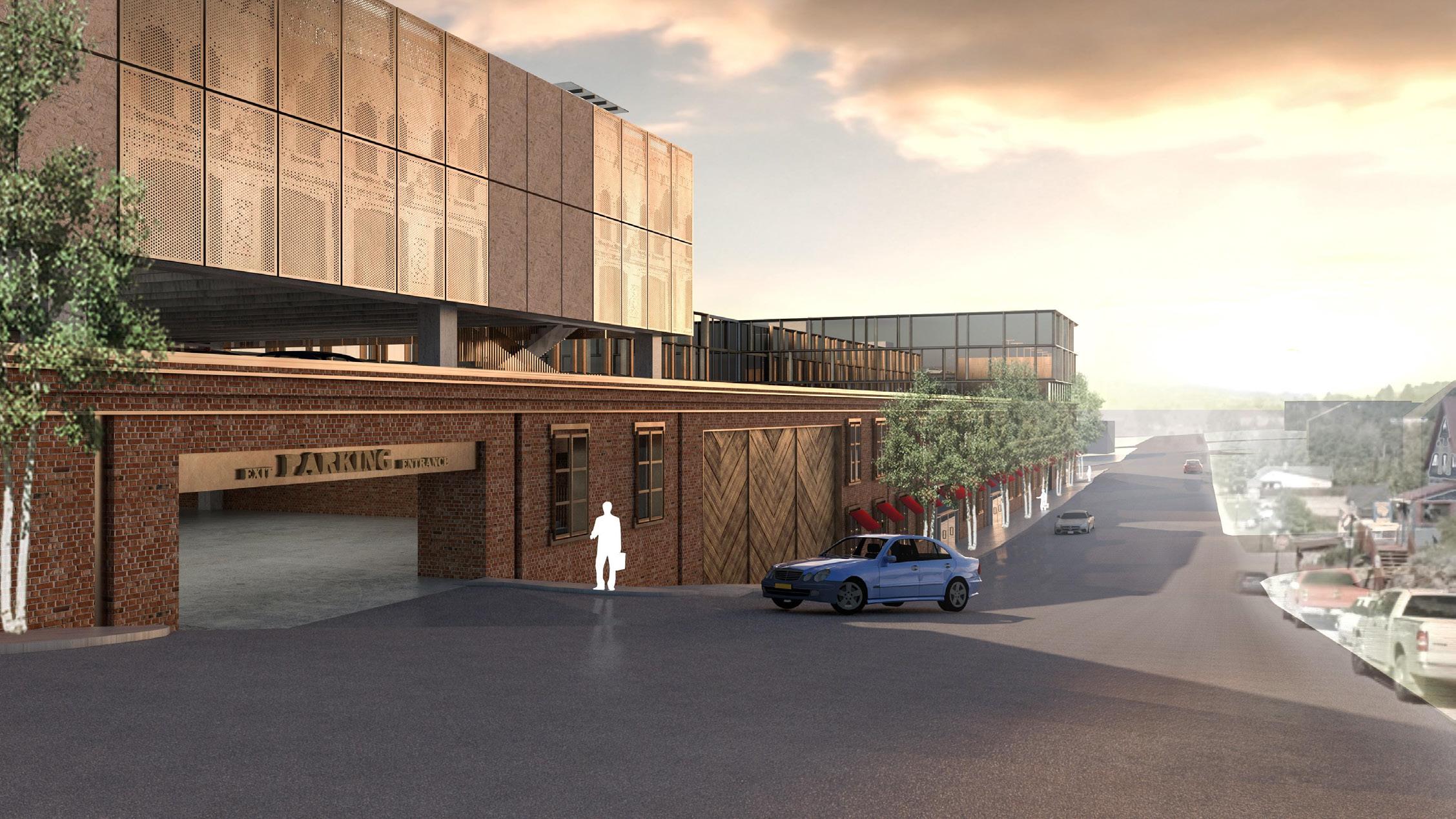
WOOD CLAD HANGAR DOORS
Material Palette | South Main Entrance View
Material Palette | North East to South West Parking View
Masonry Alignment - Overall South Elevation - Zone 1A
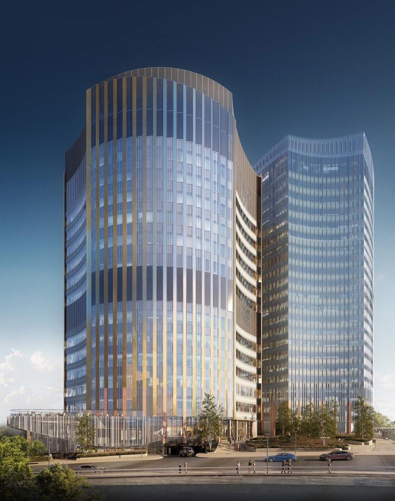
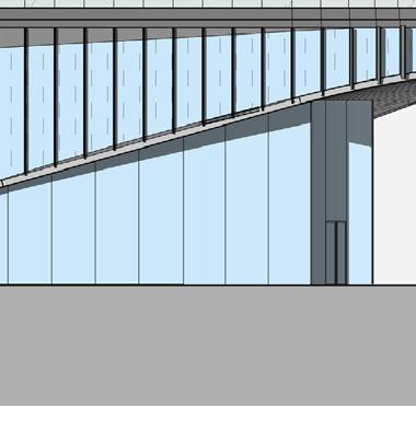
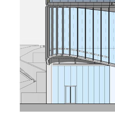
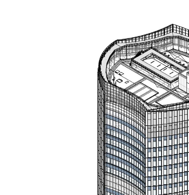
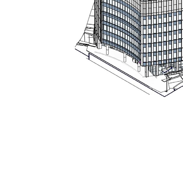
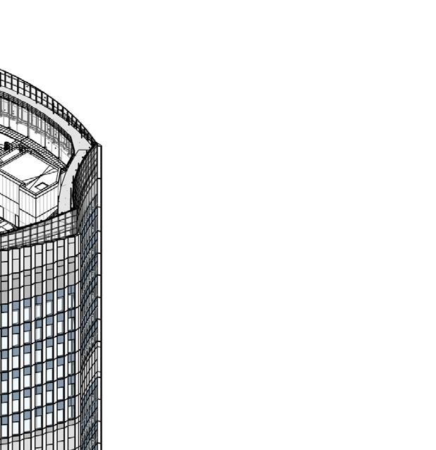
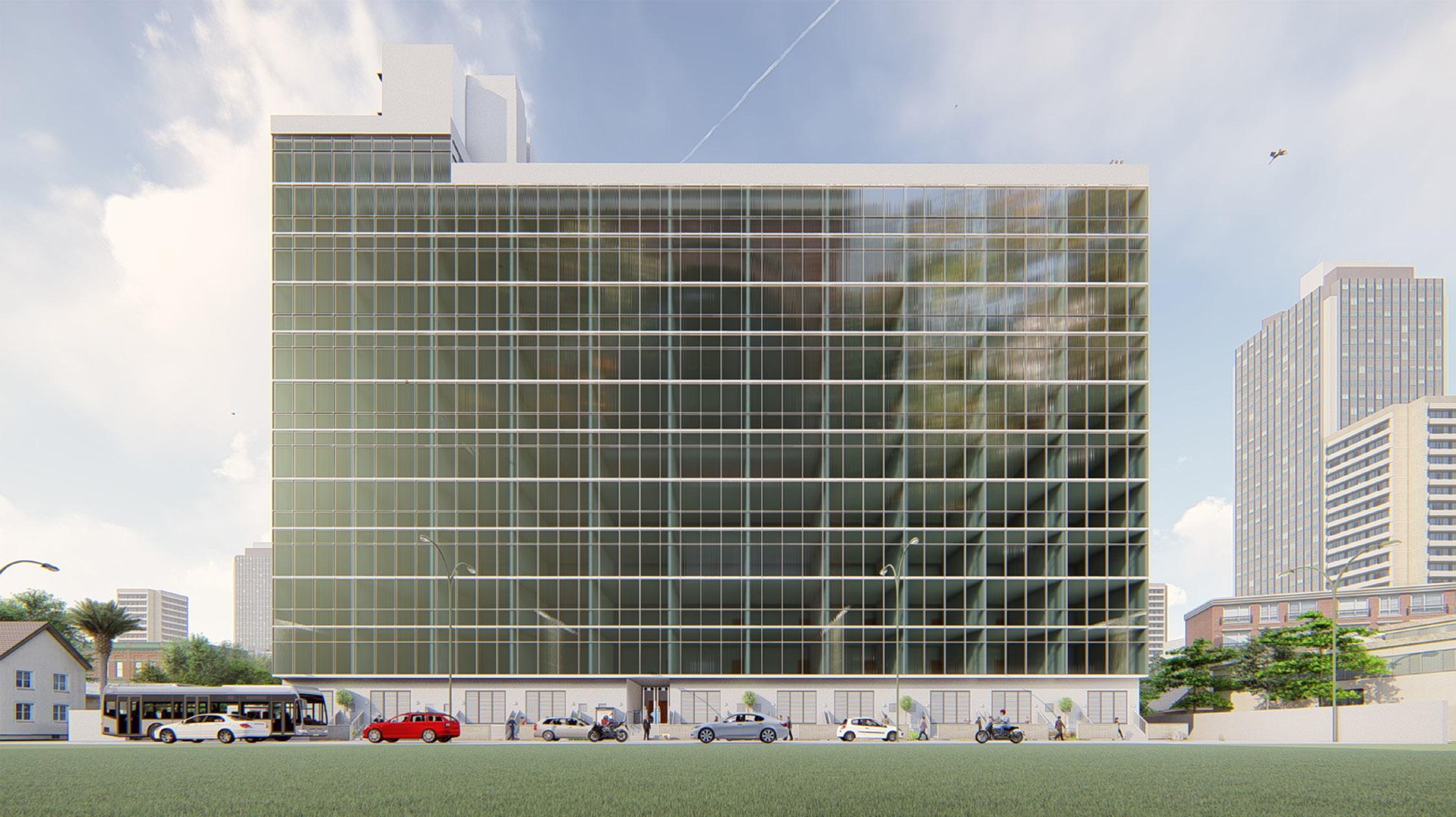
I joined the project during the Construction Documentation phase and was actively involved for around four months. With expertise in detailing the exterior envelope, I quickly took on the responsibility of developing intricate details for the lower half of the building’s shell. Among the most complex aspects were the podium studies, development of the hexagonal column details with varying landscaping and glazing conditions; detailing of unitized curtain wall system with the terracotta tiling; the landscape area atop the podium comprising both paved and non-paved surfaces and coordinating these details with vendors and consultants to ensure seamless integration. Additionally, I was responsible for developing nested Revit families for exterior unitized systems, ensuring accuracy and efficiency in the project’s digital representation.
061600 -5/8" GLASS-MAT GYPSUM WALL SHEATHINGTYPE X
METAL EXTENSIONS BEYOND
REFER TO STRUCTURAL
074229 -TERRACOTTA PANEL
078100 -CEMENTITIOUS SPRAY ON FIREPROOFING
072726 -FLUID-APPLIED MEMBRANE AIR BARRIERS
-PODIUM SHUTTLE STAIR
TYPE KEYNOTE
BW-1OPEN JOINT INTERIOR ACM BEAM WRAP WITH METALLIC MICA COATING FINISH TO MATCH CURTAIN WALL MULLIONS. CONCEALED INTEGRATED LINEAR LED LIGHTING.
CW-1UNITIZED CURTAIN WALL SYSTEM WITH BUTT GLAZED MULLIONS. MULLIONS TO HAVE METALLIC MICA COATING FINISH.
CW-2POINT MOUNTED GLAZING CURTAIN WALL SYSTEM WITH NO HORIZONTAL MULLIONS. INSET LINEAR COLOR LED LIGHTING FIXTURE IN REVEAL OF CUSTOM PROFILE EXTERIOR VERTICAL MULLIONS. INTERIOR BUTT GLAZED JOINTS WITH EXPOSED BLACK PINCH PLATE FASTENER TABS. MULLIONS TO HAVE METALLIC MICA COATING FINISH.
CW-3POINT MOUNTED GLAZING CURTAIN WALL SYSTEM WITH NO HORIZONTAL MULLIONS. VERTICAL MULLIONS AT INTERIOR EXTERIOR BUTT GLAZED JOINTS WITH CONCEALED TOGGLE CONNECTIONS (NO PINCH PLATES). MULLIONS TO HAVE METALLIC MICA FINISH.
GB-1EXTERIOR TEMPERED GLASS BALUSTER WITH CONCEALED MOUNTING BELOW ALUMINUM FASCIA OPEN JOINT GLASS EDGES
LV-2VERTICAL ALUMINUM LOUVERS CONCEALED JOINTS FOR CONTINUOUS LOUVER EXPRESSION WITH INSULATED BLANK OFF PANEL. METALLIC MICA FINISH.
ML-1UNITIZED CURTAIN WALL SYSTEM WITH OPEN JOINT EXTERIOR RAINSCREEN ALUMINUM BACKED HONEYCOMB PANELS WITH METALLIC MICA COATING FINISH AND INSULATED METAL BACKPAN. ALUMINUM PANELS TO HAVE METALLIC MICA COATING FINISH.
ML-2UNITIZED CURTAIN WALL SYSTEM WITH OPEN JOINT EXTERIOR RAINSCREEN ALUMINUM BACKED HONEYCOMB PANELS WITH UNINSULATED METAL BACKPAN. ALUMINUM PANELS AND EXPOSED BACKPANS TO HAVE METALLIC MICA COATING FINISH.
ML-3HEAVY GAUGE ALUMINUM FACIA/COPING, METALLIC MICA COATING FINISH TO MATCH CURTAIN WALL.
ML-5ALUMINUM COLUMN COVERS WITH METALLIC MICA COATING FINISH.
SA-1NON-ACCESSIBLE FIXED TOWER SOFFIT METALLIC MICA FINISH TO MATCH CURTAIN WALL.
SA-2NON-ACCESSIBLE FIXED EXTERIOR ALUMINUM SOFFIT SYSTEM METALLIC MICA FINISH
SA-3ACCESSIBLE OPEN JOINT EXTERIOR ALUMINUM SOFFIT SYSTEM METALLIC MICA FINISH.
ST-1OPEN JOINT GRANITE RAINSCREEN SYSTEM, WITH INSULATION GRANITE PANELS WITH HONED FINISH.
ST-2SEALED JOINT GRANITE RAINSCREEN SYSTEM, WITH INSULATION GRANITE PANELS WITH HONED FINISH.
TE-1UNITIZED CURTAIN WALL SYSTEM WITH OPEN JOINT TERRACOTTA HOLLOW CORE PANELS (ASSEMBLY FOR COLUMN WRAP, NO INSULATED METAL BACKPAN). TERRACOTTA TO MATCH EXISTING ROBERTS TOWER
TE-2UNITIZED CURTAIN WALL SYSTEM WITH OPEN JOINT TERRACOTTA HOLLOW CORE PANELS AND INSULATED METAL BACKPAN. TERRACOTTA TO MATCH EXISTING ROBERTS TOWER
Level 1 Structural Framing Plan | N.T.S
HEXAGONAL COLUMN FRAMING
NOTE: PLEASE REFER TO A401 & A402 FOR WALL AND ROOF ASSEMBLY DETAILS
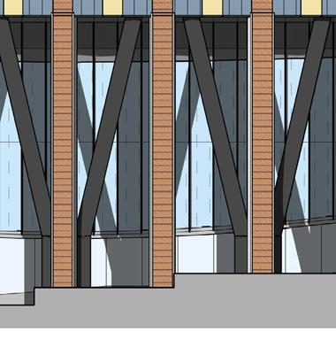
The floor plate is supported by hexagonal columns, which form the peripheral boundary at the podium level and seamlessly merge into the pleated superstructure. These columns feature a terracotta finish, selected to establish a visual connection with the Roberts Center.
3CONSTRUCTION
1ISSUED FOR CONSTRUCTION02/10/2023
0ISSUED FOR PERMIT 11/17/2022
054000 -Z-FURRING 054000 -CFMF
078100
HSS JAMBS
054000 -CFMF
HSS
TIE STRONG-DRIVE TB WOOD-TO-STEEL SCREWS @ 18" OC (MAX)
HSS JAMBS BELOW FOR
03
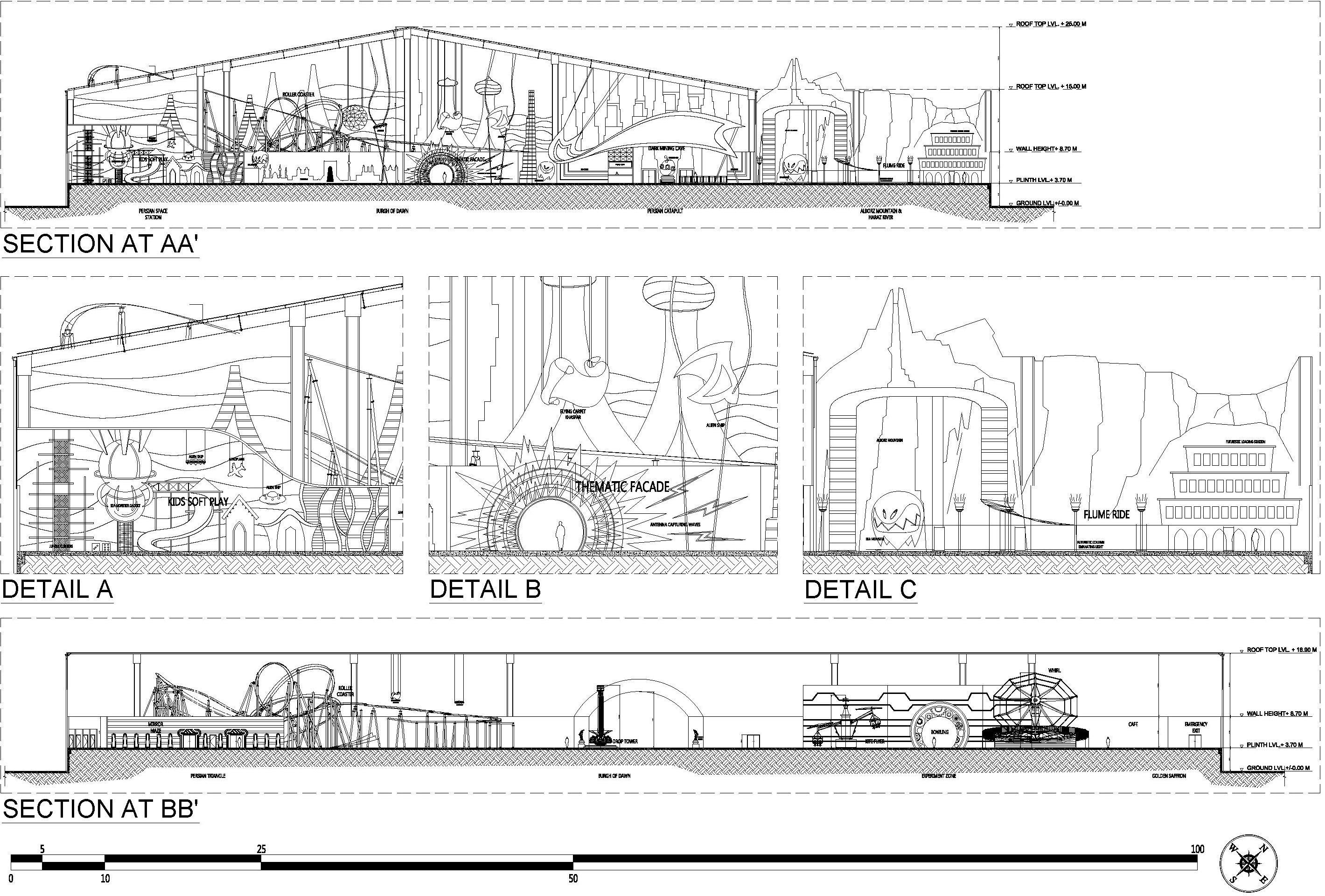
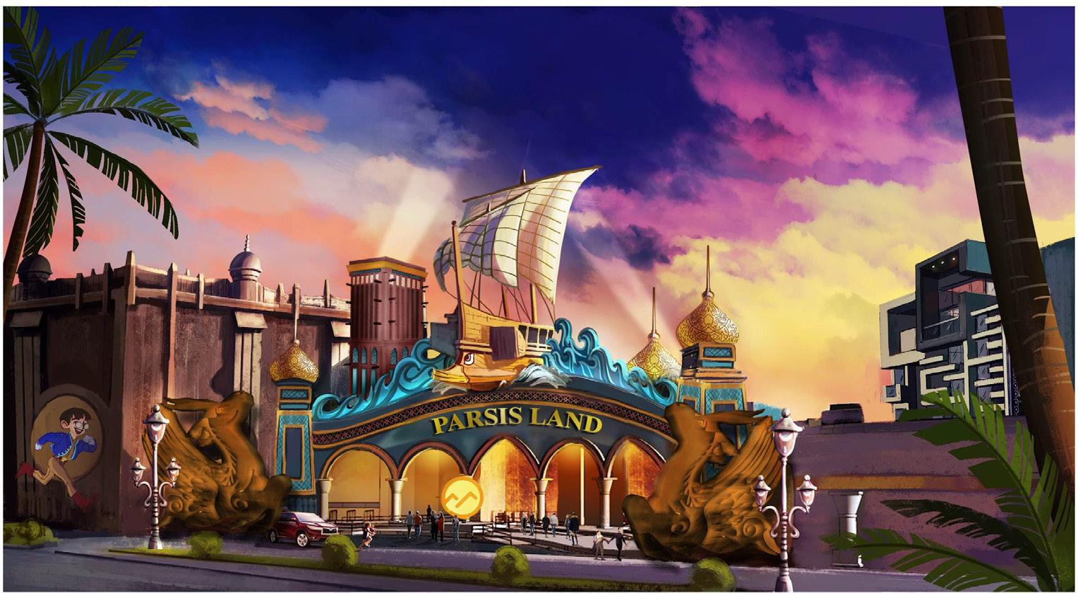
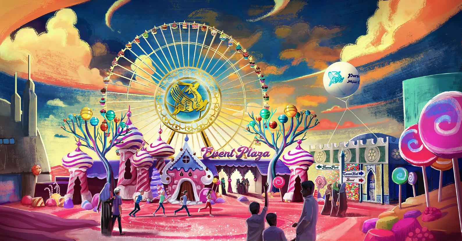
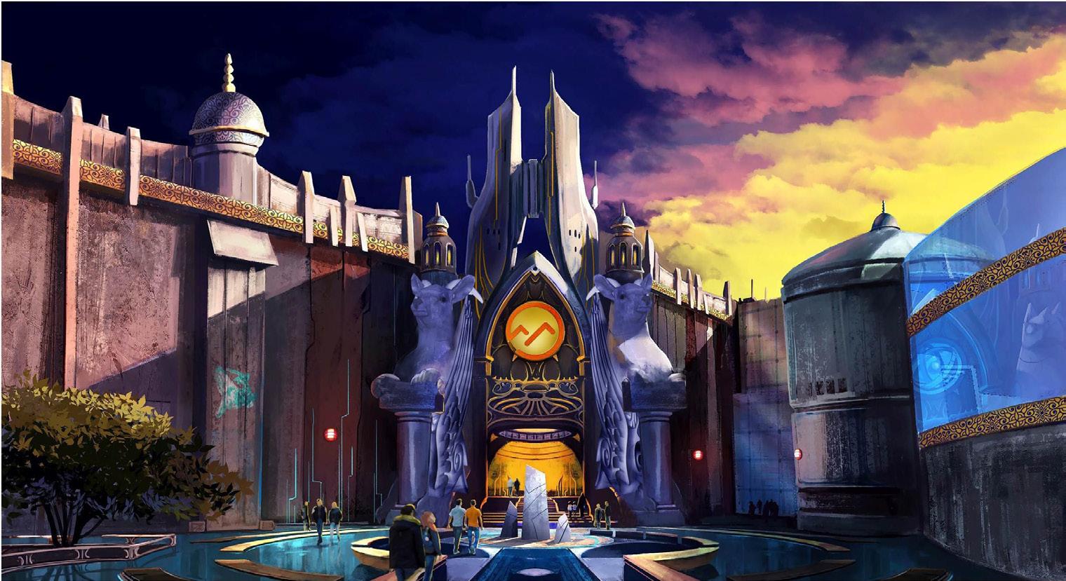
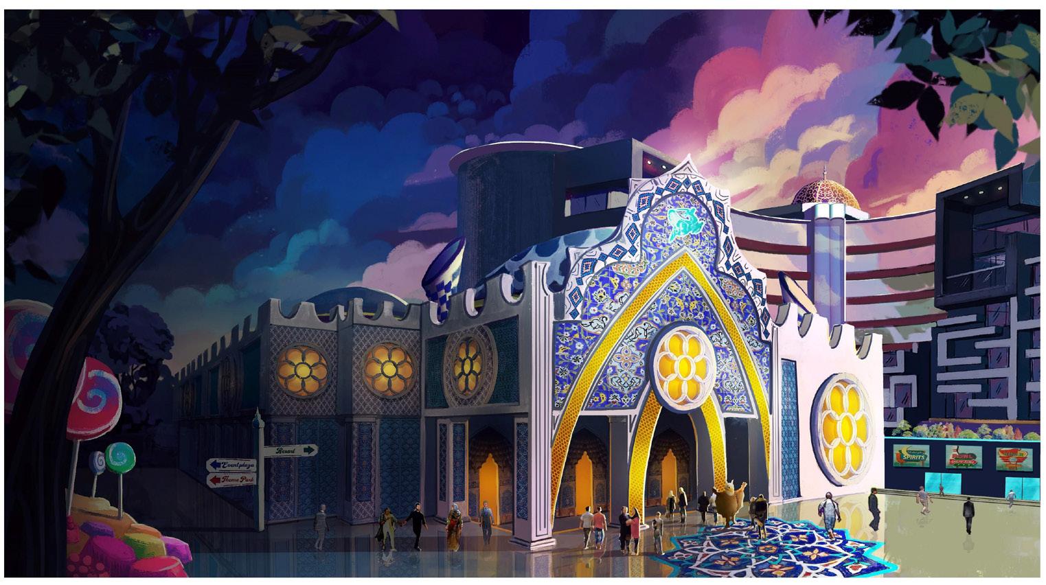
KISH ISLAND THEMED AMUSEMENT PARK AND RESORT (KTAPR)
Kish Island | Iran
2019-20 | Concept Design Completed
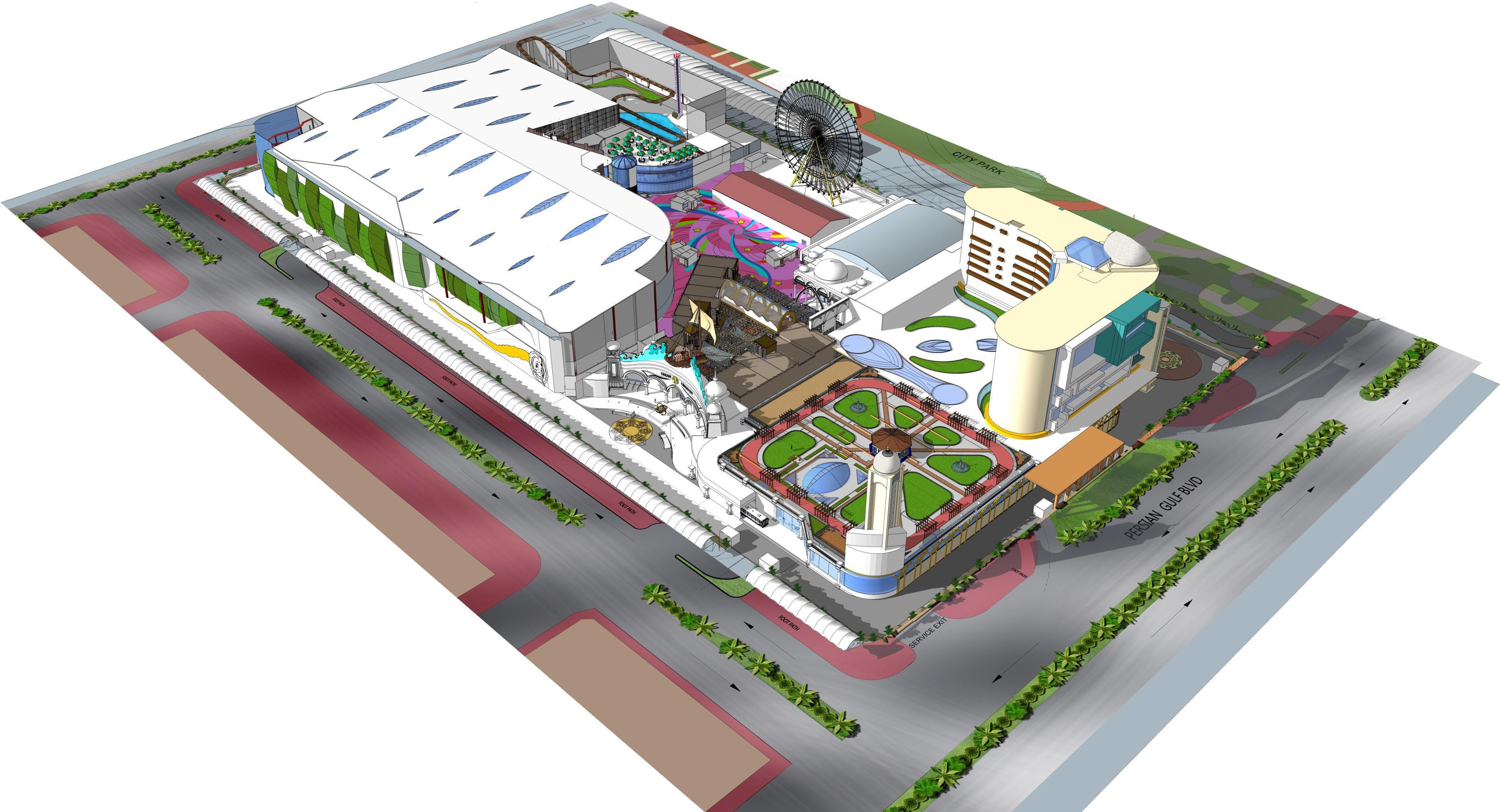
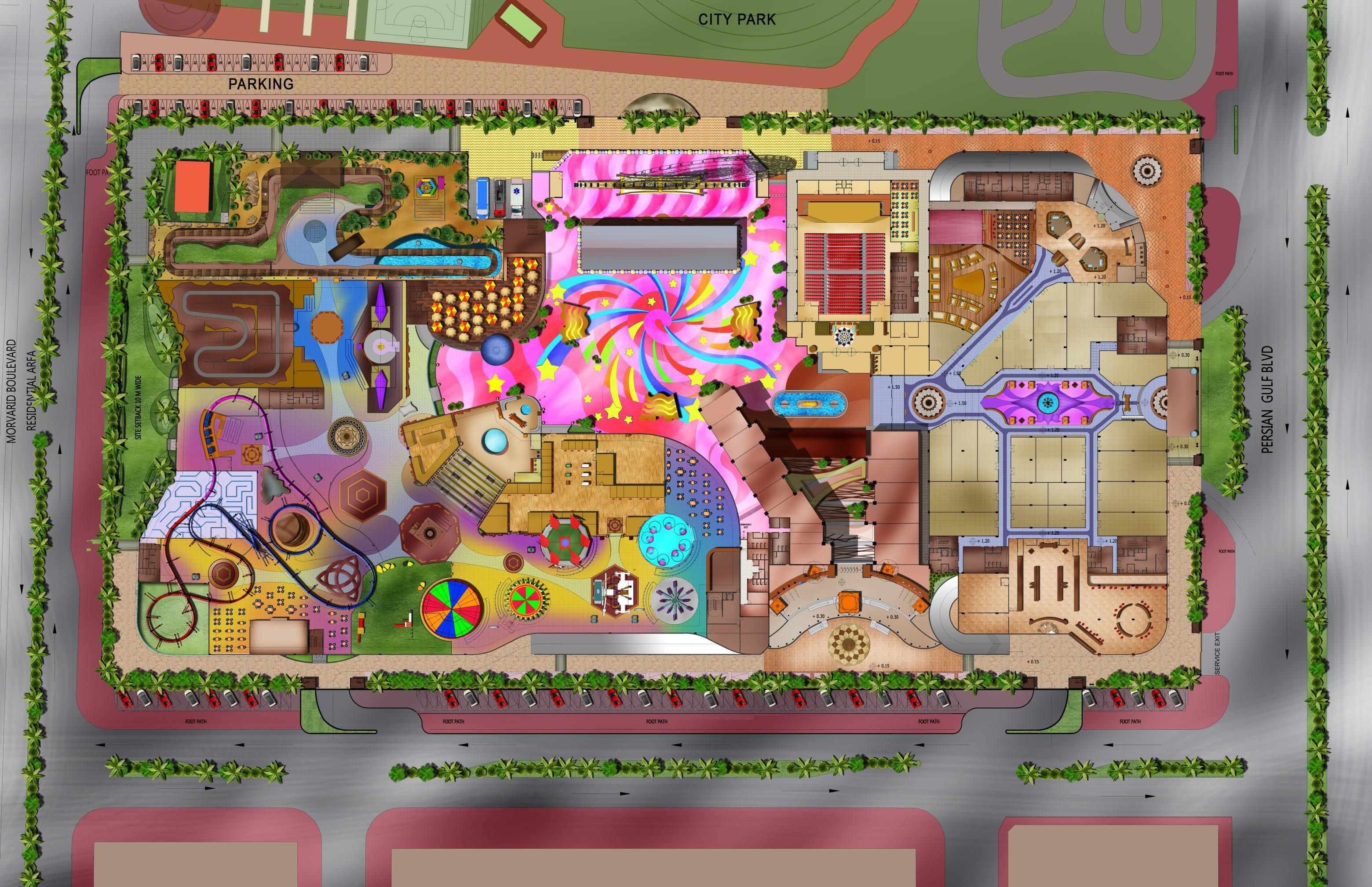
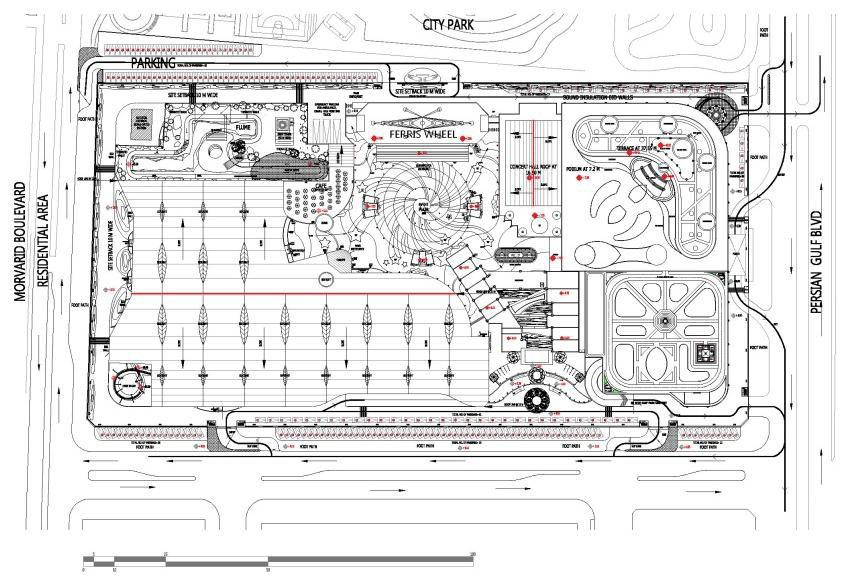
At Sanderson Group, KTAPR was the first project I was involved with during the Concept Design Phase. Over approximately eight months, I gained extensive insight into the theme park industry from both design and development perspectives. The project required close coordination between the Mumbai and UAE offices, with my primary focus on developing the theme park within the overall master plan. My responsibilities included designing plans, sections, and elevations, conducting a comparative analysis of theme park ride inventory, and coordinating ride sizes with vendors. Additionally, I took on a new role by collaborating with the art director and artists to develop the exterior skin of the project. This experience deepened my understanding of how international entertainment destinations respond to their site and culture, as well as how thematic architecture can evoke emotions both literally and abstractly.
Contribution: Concept Design Package - Master Planning, Theme Park Planning and documentation, Art Direction, Vendor Coordination, Inventory Analysis
The attraction mix available in the neighboring parks (see appendices) has been summarized below While there are some notab le opportunities – dark ride, coasters, shows, transpport – some of these will not be feasible because of budget & space limitations
Entrance Zone
Event Plaza
Theme Park
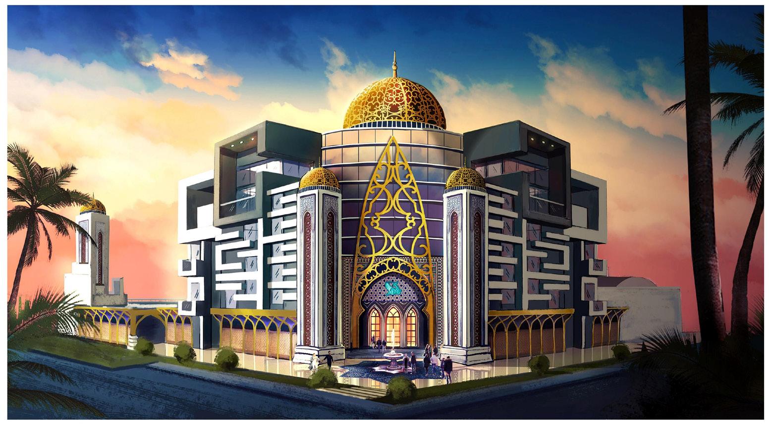
Concert Hall
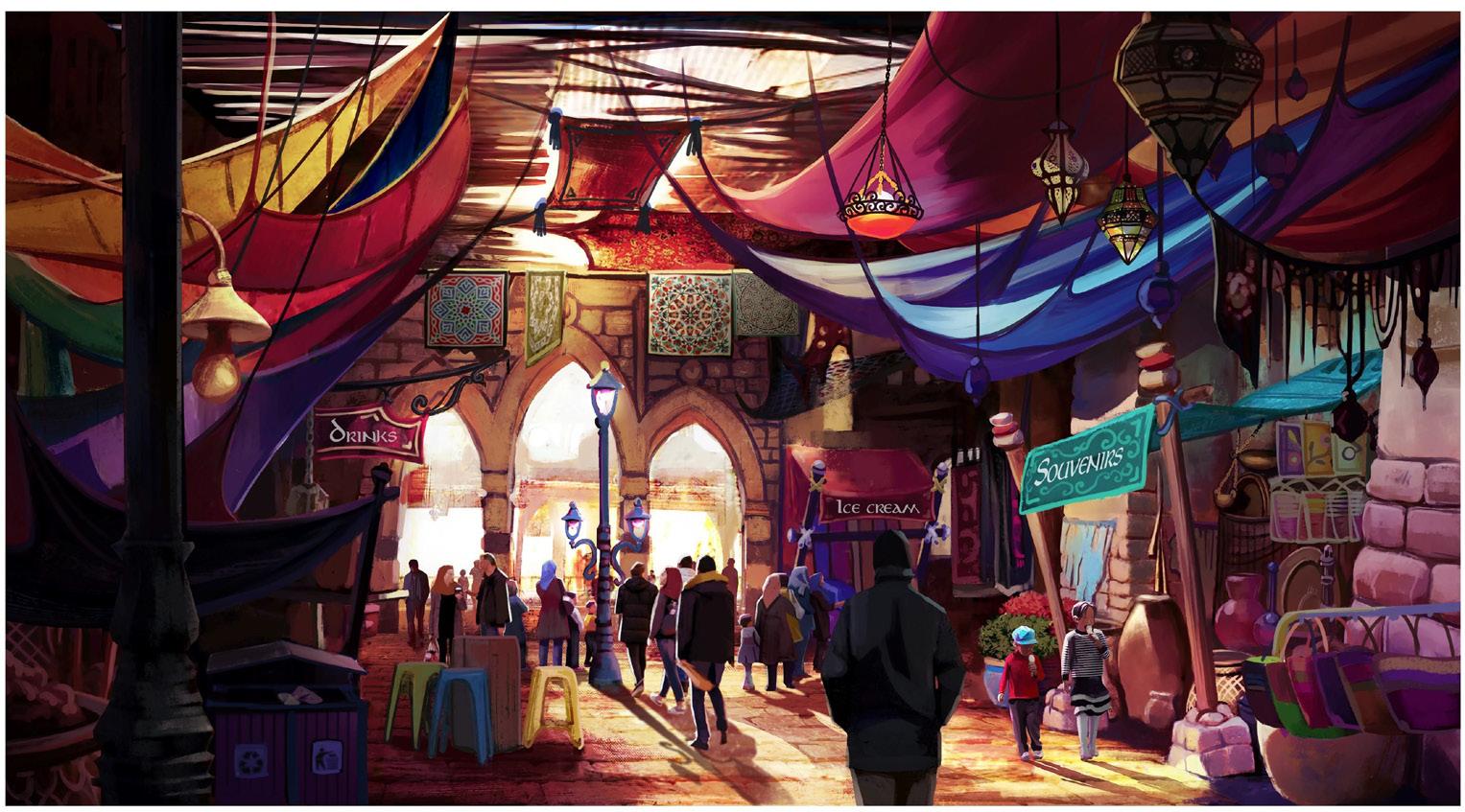
Persian Bazaar
Resort
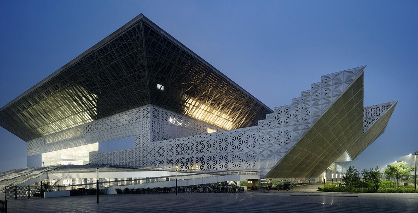
INDIA INTERNATIONAL CONVENTION AND EXHIBITION CENTER
Delhi | India
2020-21 | Phase 1 Construction Completed
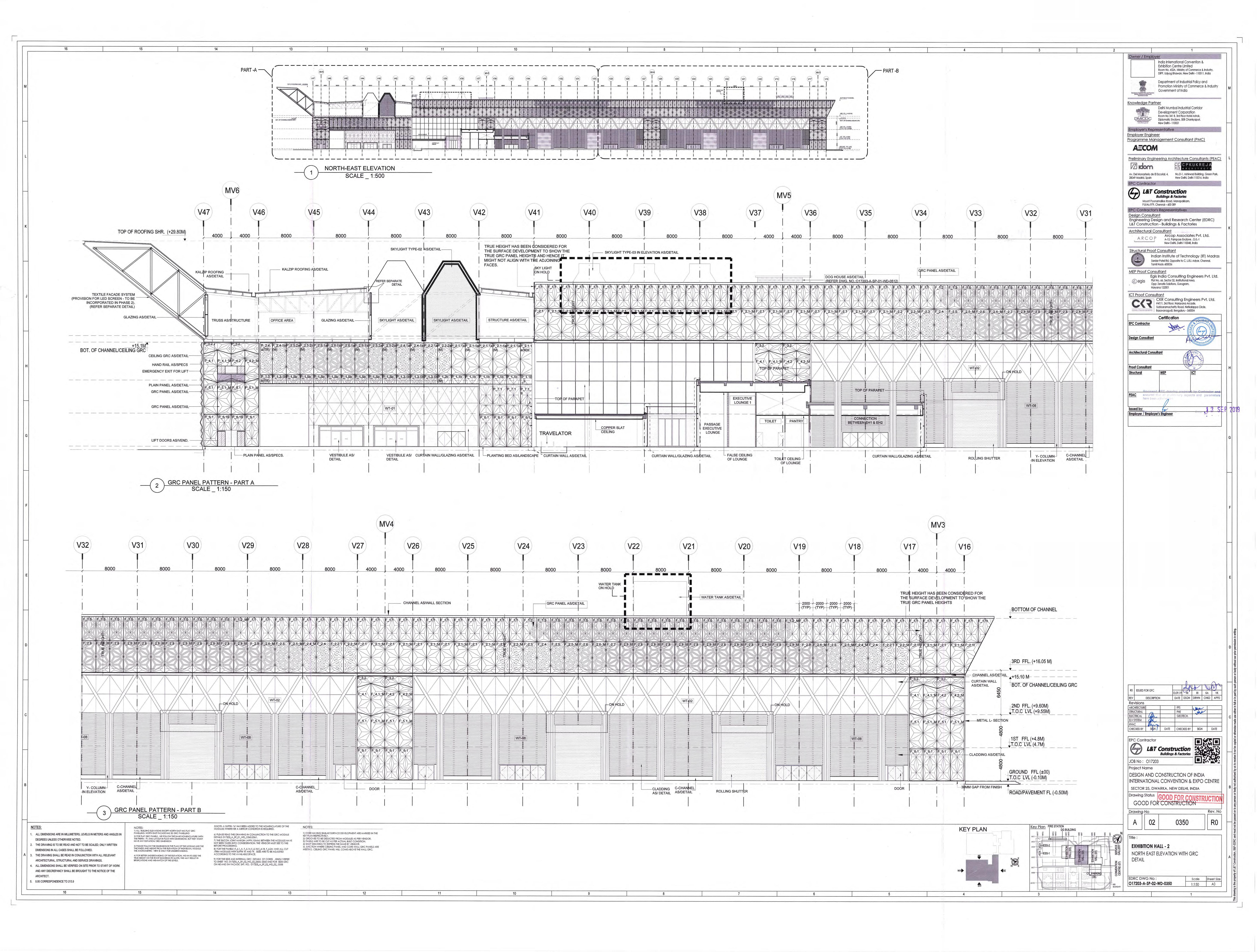
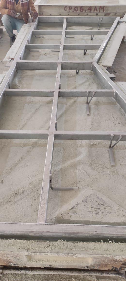
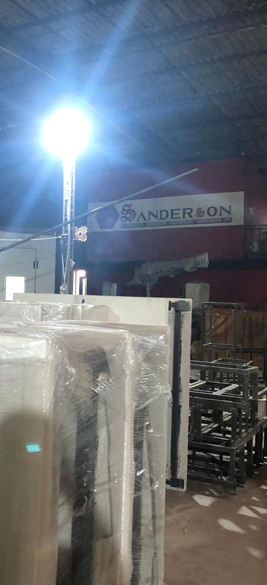
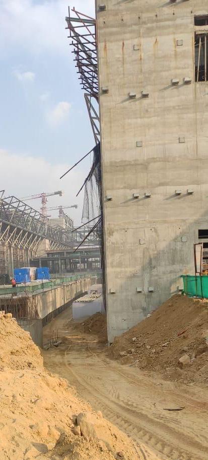
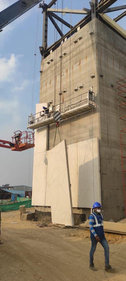
IICE, India’s largest convention center, recently completed in Delhi, showcases an architectural language that reflects the country’s rich ornamental heritage, making it a prime venue for international events. The South Zone elevation and ceiling panels were subcontracted to Sanderson Group by Larsen & Toubro for the manufacturing and installation of Glass Fiber Reinforced Concrete (GFRC) panels. I led the development of shop drawings, ensuring seamless coordination with the general contractor, Larsen & Toubro. Additionally, I assisted my project architect in overseeing the manufacturing process at Sanderson Group’s Delhi and Mumbai factories, conducting site visits for product finish inspections, and strategizing installation processes.
Project Manager: Harshad Rajadhyax
Softwares: Autocad, MS Office
Contribution: Developing shop drawings for the manufacturing, overseeing assembly, and installation of Glass Fiber Reinforced Concrete (GFRC) panels.
PANEL
GRC PANEL
MIRRORED PANEL
GRC PANEL
MIRRORED PANEL
CP_01.1A
CP_01.1A M
CP_01.1B
CP_01.1B M
2 NOS. 10 THK PLATE DONE BY OTHERS
8 THK PLATE DONE BY OTHERS
2 HOLE FOR 2 M10 BOLTS 45mm c/c
ANGLE CLEAT 75X75X10mm WITH 20Ø HOLES 90mm C/C OVERALL FILLET WELDED TO STUD FRAME
CP_01.1.1A
M16 BOLTS TO BE PROVIDED BY L&T
Panel Drawings by Architect (mm)
Section of Wall Panel
CP_06.1.2A
2 HOLE FOR 2 M10 BOLTS 45mm c/c F_1.3 (1.82 kpa)
125x75x10mm PLATE WITH 25x40mm SLOT HOLE FOR LIFTING DURING INSTALLATION
ANGLE CLEAT 75x75x170x10mm WITH 20 Ø HOLES 90mm C/C OVERALL FILLET WELDED TO STUD FRAME
FLEX ANCHOR (FL) Ø 10mm
TYPICAL
NOTE: 1. LP = LIFTING POINT.
2. F = FIXING POINT.
3. FL = FLEX ANCHOR Ø 10mm.
4. GP = PERMANENT GRAVITY ANCHOR Ø12mm.
5. GT = TEMPORARY GRAVITY ANCHOR (TO BE CUT BEFORE INSTALLATION).
6. (B-3) =122x61x3.5 RHS (GRADE 310MPA STEEL).
7. (B-4) =66x33x3.6 RHS (GRADE 310MPA STEEL)
8. POLYPROPYLENE SLEEVE ON ALL BONDED FLEX ANCHOR LENGTH 11mm Ø & GRAVITY ANCHOR LENGTH 25mm Ø
9. THIS DWGS TO BE READ IN CONJUNCTION WITH PATTERN DWG NO.GRC-02-WP-0004-R0
10. Ref.RE DWG NO- O17203-GRC-SP-01-NU-4005
11. FOR FLEX ANCHOR DETAIL AT-P, LIFTING POINT-DETAIL AT-Q, FIXING POINT DETAIL AT-R & S. REF. SHEET NO.GRC-02-STR-WP-0120-R0
Elevation of Wall Panel | N.T.S.
1. Development of Outer Frame and Studs based on the dimensions from Shop Drawings
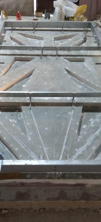
2. Identification of Connectors, Washers and Bolts based on wind loads
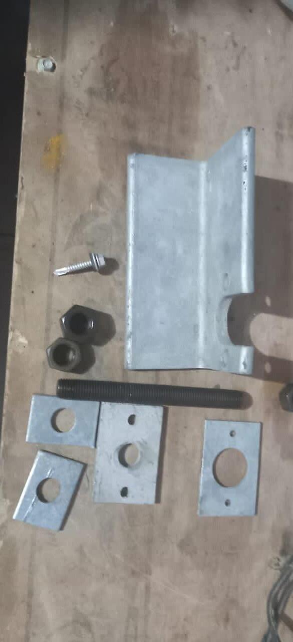
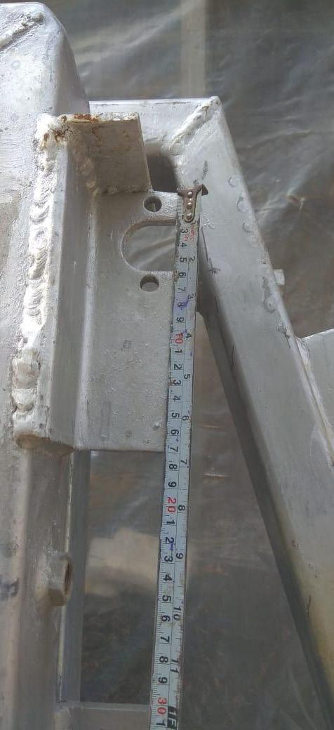
3. Cross-checking the locations of connecting cleats
4. Attaching the Flex Anchors from the Studs to the GFRC Panels through Bonding Pads
of the
6. Cross-checking the locations of the Fixing Points
7. Lifting the panels through defined points in the stud frame
8. Cross-Checking the alignments of Fixing Points and Mounting Cleats after installation
5. Packaging
cured panels
05
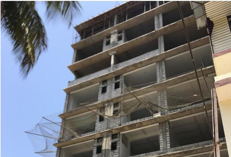
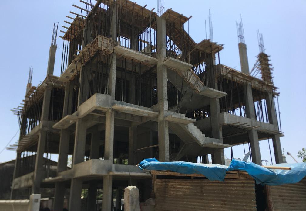
NAWALKAR WADI:
Mixed Use Development and Affordable Housing Initiative
Mumbai | India
2018 | Construction Completed
The Nawalkarwadi project was one of the most complex projects I worked on during my time at Mahendra Davda Architects. When I joined the project, the affordable housing tower was already intricate; Retail Building 1 and the School Building were under construction, while the newly proposed retail building near the railway tracks required amended drawings. As part of the architectural team, my primary responsibility was to analyze the newly implemented Development Control Regulation 2034 of Mumbai, focusing on increased floor area ratios, master plan development, and code compliance drawings for the new retail building. Additionally, I coordinated with the railway agency and fire department to obtain necessary approvals. This project remained a continuous engagement for two years, during which my responsibilities expanded to include site visits for slab inspections, as well as client and contractor coordination for the master plan.
Principal Architect: Mahendra Davda
Softwares: Autocad, Revit
Contribution: Code Compliance Drawings, Master Plan
Development, Client and Consultant Coordination, Railway and Fire Authority Coordination and drawings.
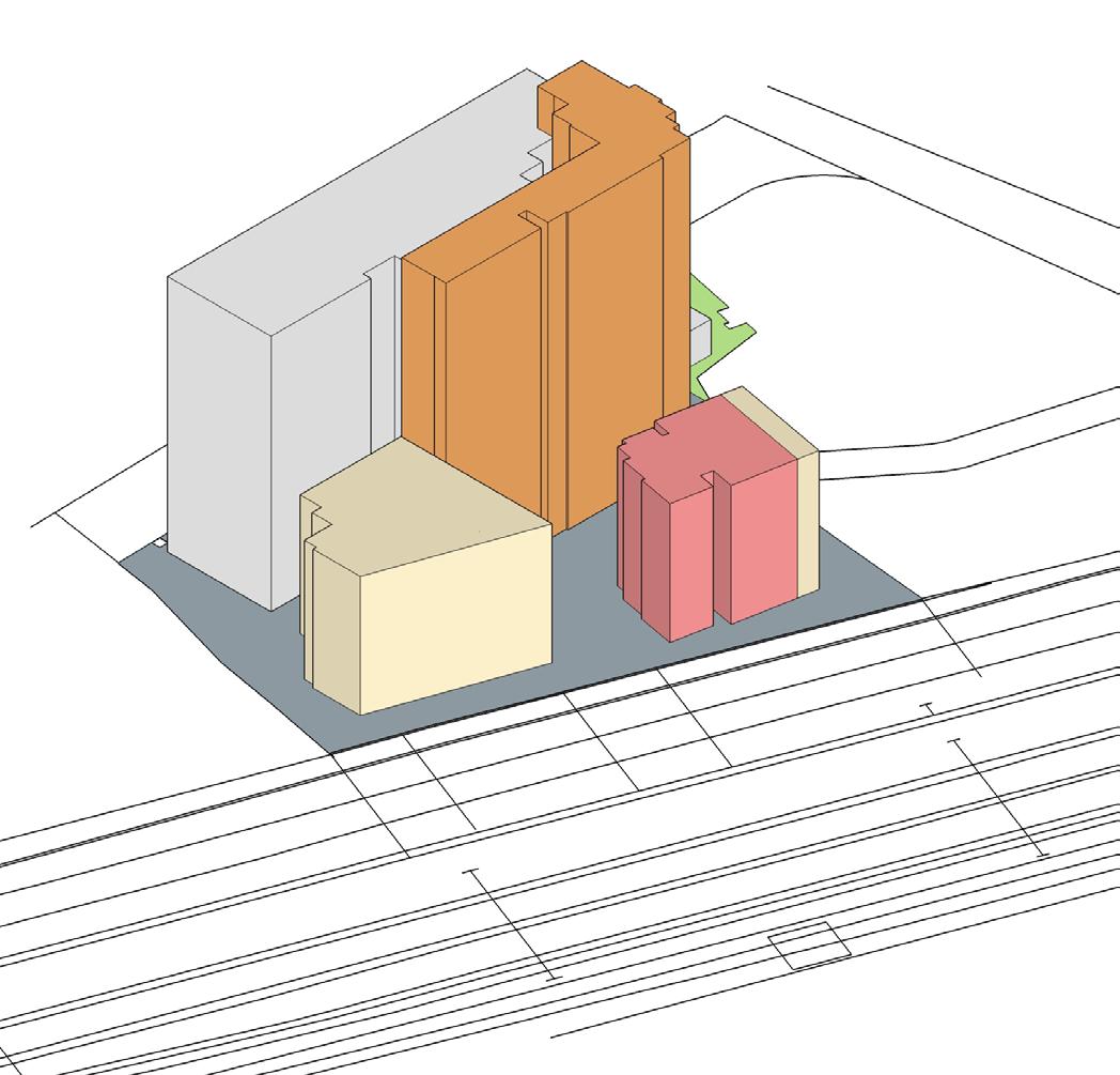
MASTER PLANNING
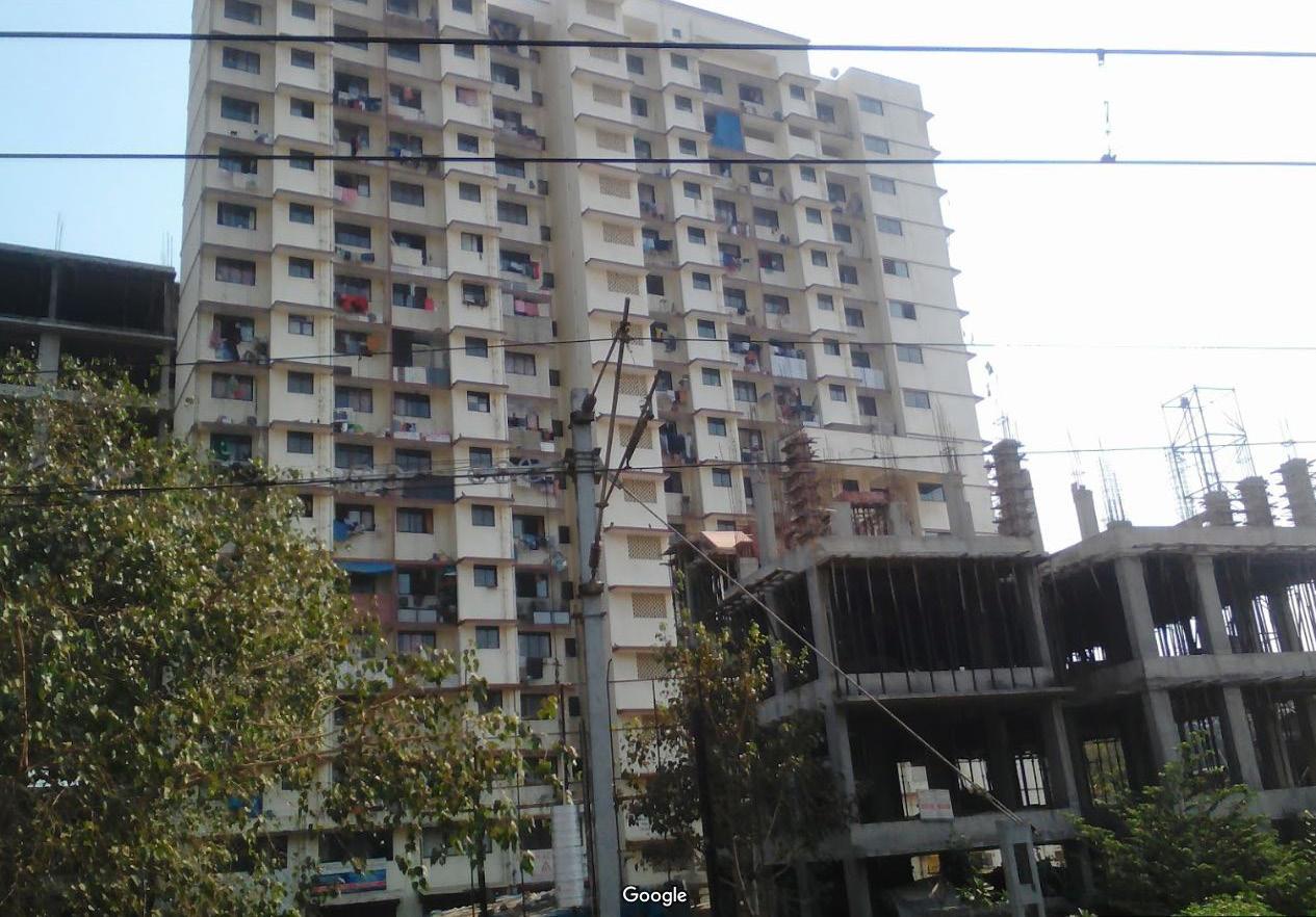
Located in a dense informal settlement near Jogeshwari East Railway Station, the site is designated for mixeduse under Mumbai’s D.P. 2034. The master plan includes a low-income residential tower, school, municipal market, retail, commercial buildings, and a parking tower. Phase 1 prioritizes the residential tower to relocate settlers, while other projects remain in progress..
CONSTRUCTION DETAILS
Plot Area: 64,000 Sqft
Gross Construction Area: 162,000 sqft
Tenement Density: > 263 Tenements per acre
Affordable Housing Tower Area: 41,570 sqft
Retail Commercial Tower 1 Area: 97,120
Retail Commercial Tower 2 Area: 23,130 sqft
Municipal Market Area: 1804 sqft
School Building Area: 13,070.65 sqft
Max. Height: 170 ft
Special Approval Agencies: Indian Railway, Civil Aviation of India
Commercial & Retail
Low Income Residential Tower
School and Municipal Market
Commercial & Retail
Railway Tracks
Zoning Diagram
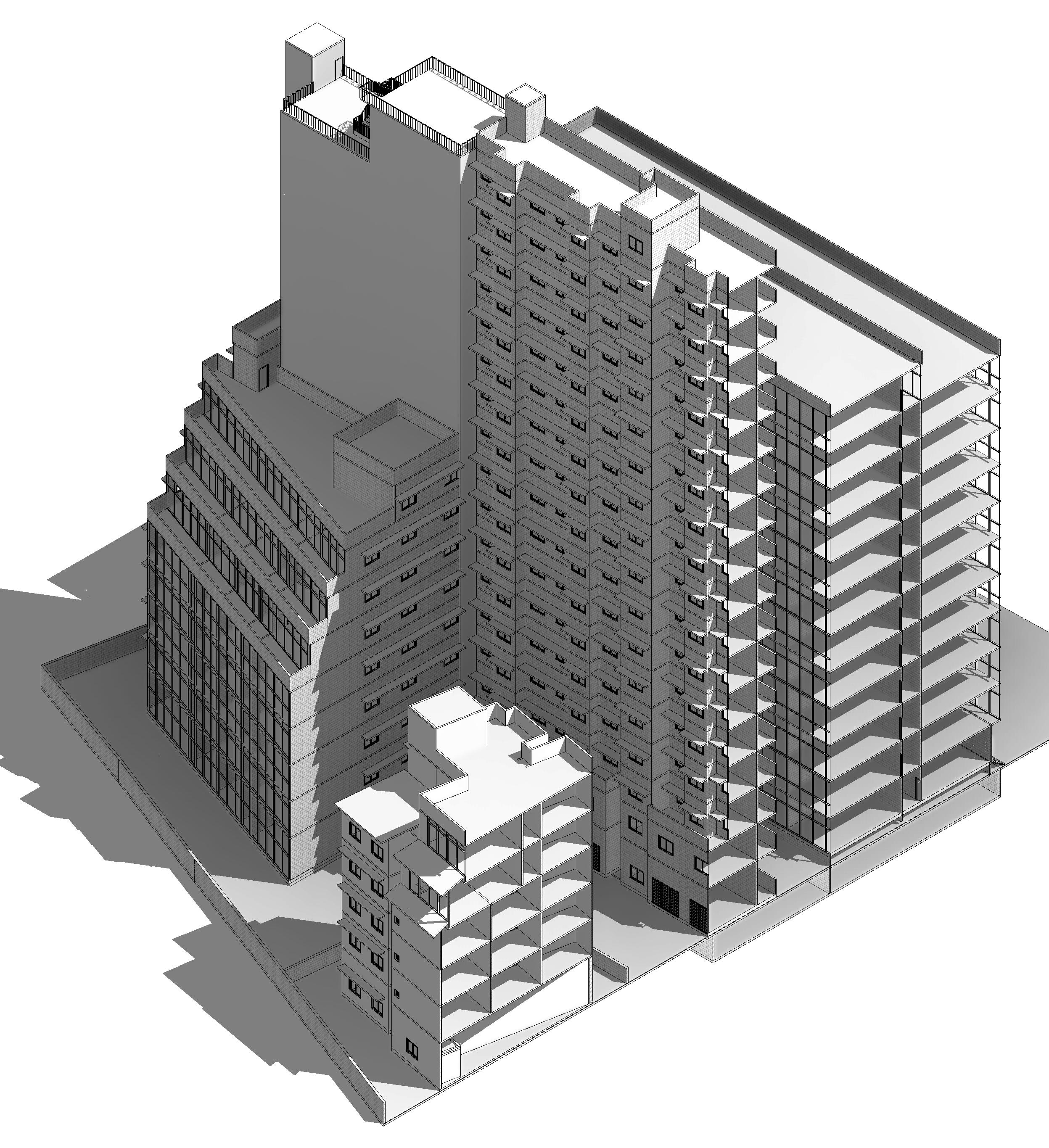
Peripheral Offset for Fire Truck Movement
Construction offset from Railway Tracks based on height
Internal Offset for Fire Truck Movement
Internal Offset for Fire Truck Movement
- 0” 19’ - 7” 19’ - 7”
19’ - 7”
Sectional Isometric View | Vertical extrusion based on fire truck movement
Retail Tower 1
Phase 1 - Completed Low Income Housing Tower
School and Municipal Market
06
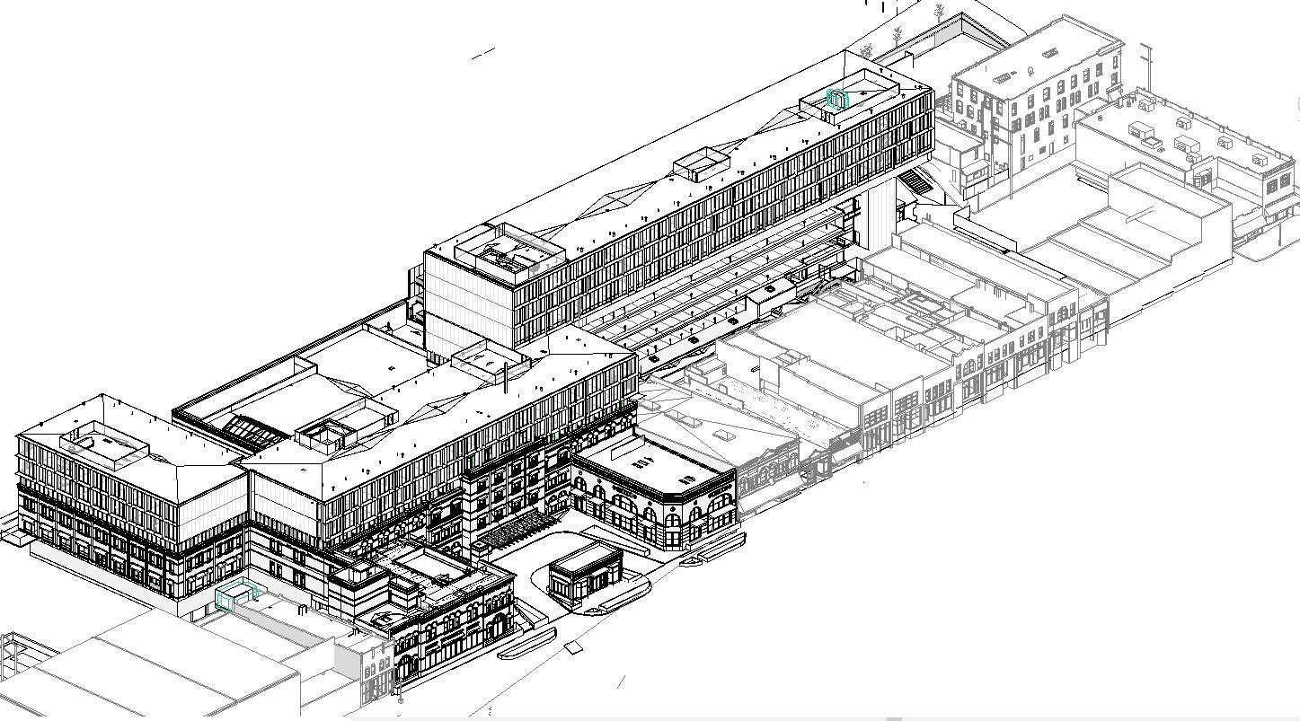
REFLECTIQUE:
City Arts and Museum
Buffalo | New York
Academic Project - M.Arch | 2024
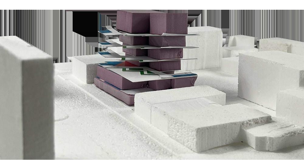
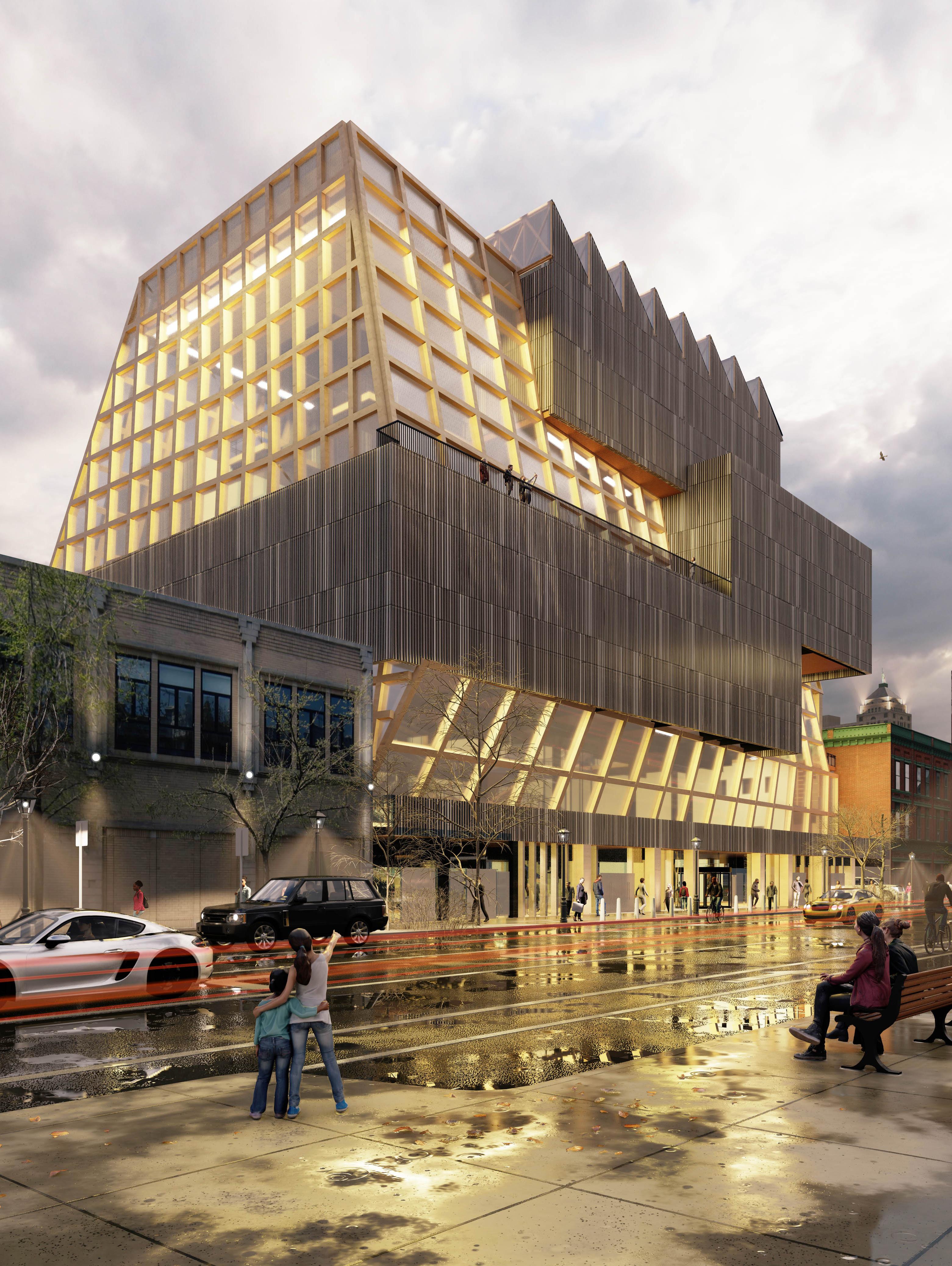
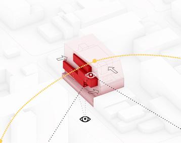
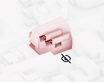
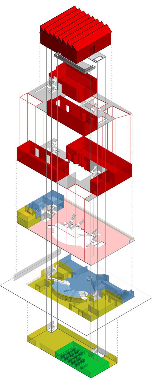
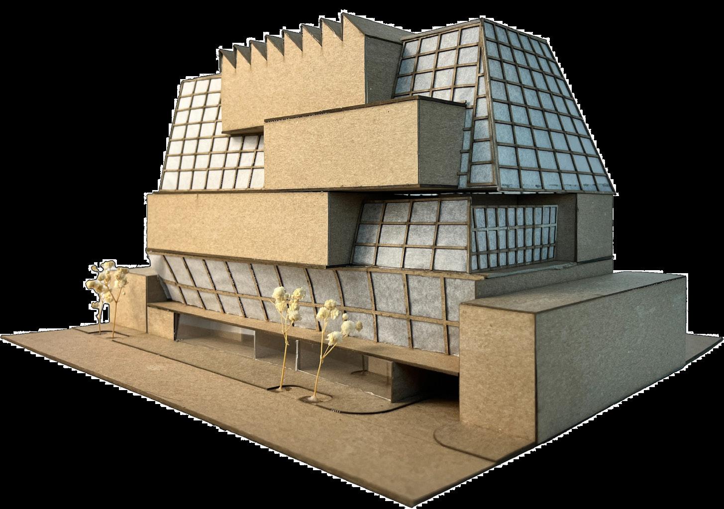
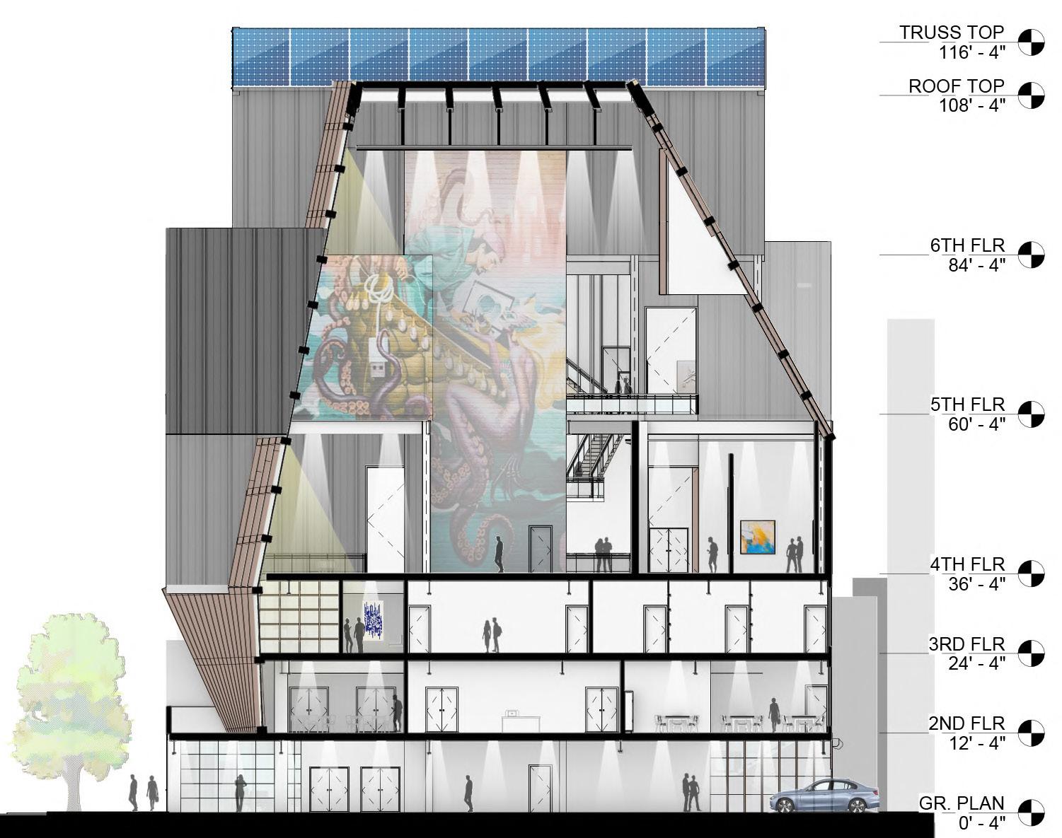
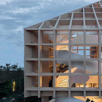
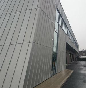
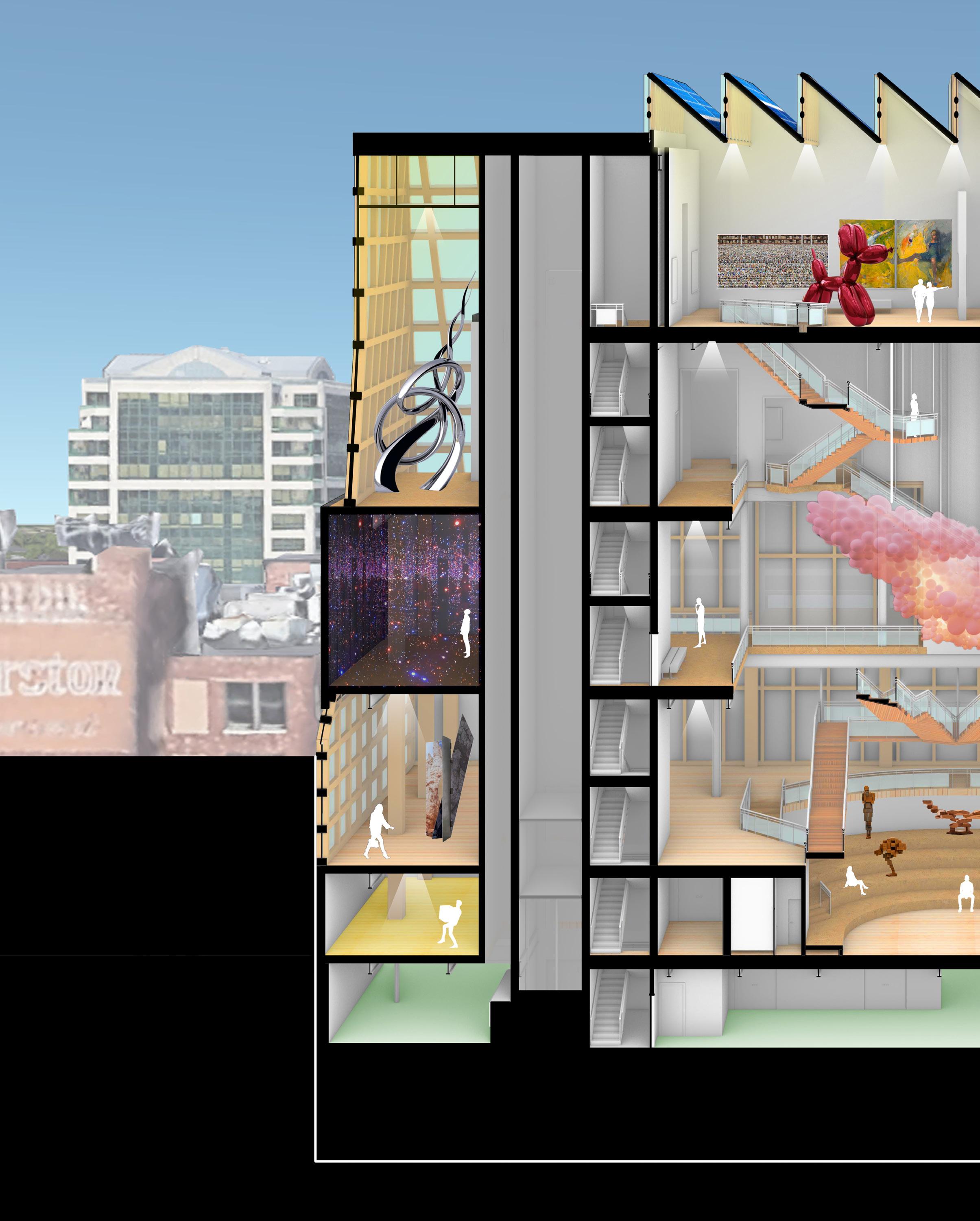
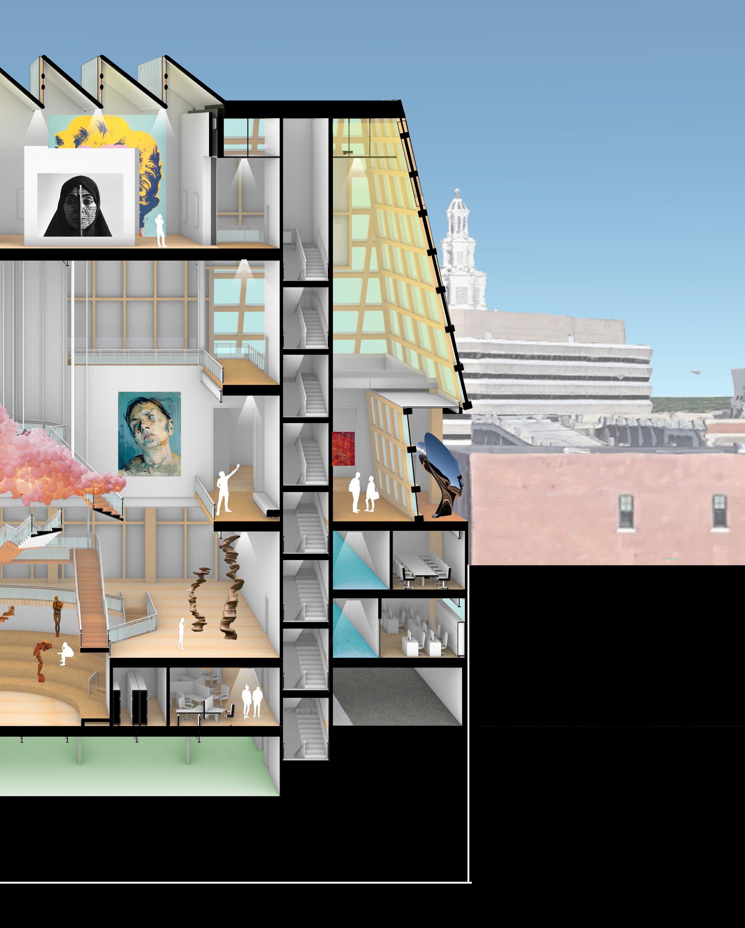
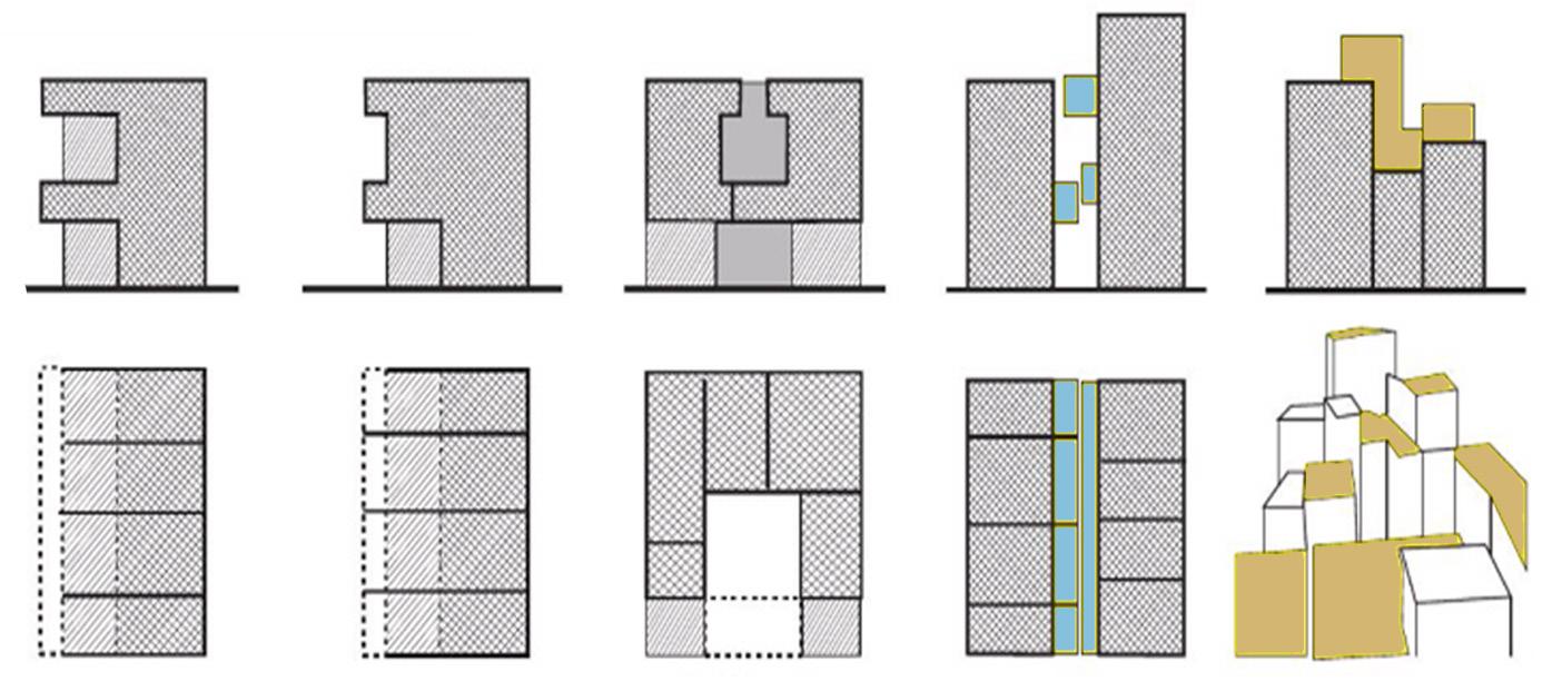
Reflectique re-imagines Buffalo’s Modernist legacy through a sustainable lens, blending history with innovation. Located on Delaware Avenue, the museum features a hybrid timberconcrete structure, energy-efficient systems like geothermal heat pumps and recycled zinc cladding, and daylightenhancing elements such as skylights and Monopan panels. Designed for Buffalo’s climate, it offers expansive indoor spaces for community interaction while promoting eco-conscious urban growth. Reflectique embodies a harmonious fusion of Modernism and sustainability, addressing both historical and future needs.
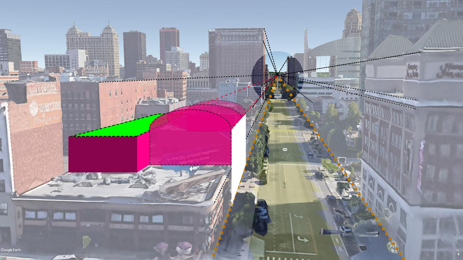
Sketch Emphasizing on McKinley`s Monument, Downtown - Buffalo
Form Development | Vertical Stacking
Gallery
Public Space, Operations Services
|
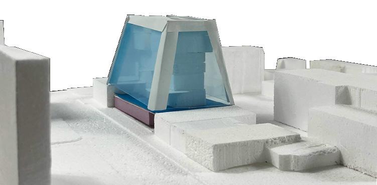
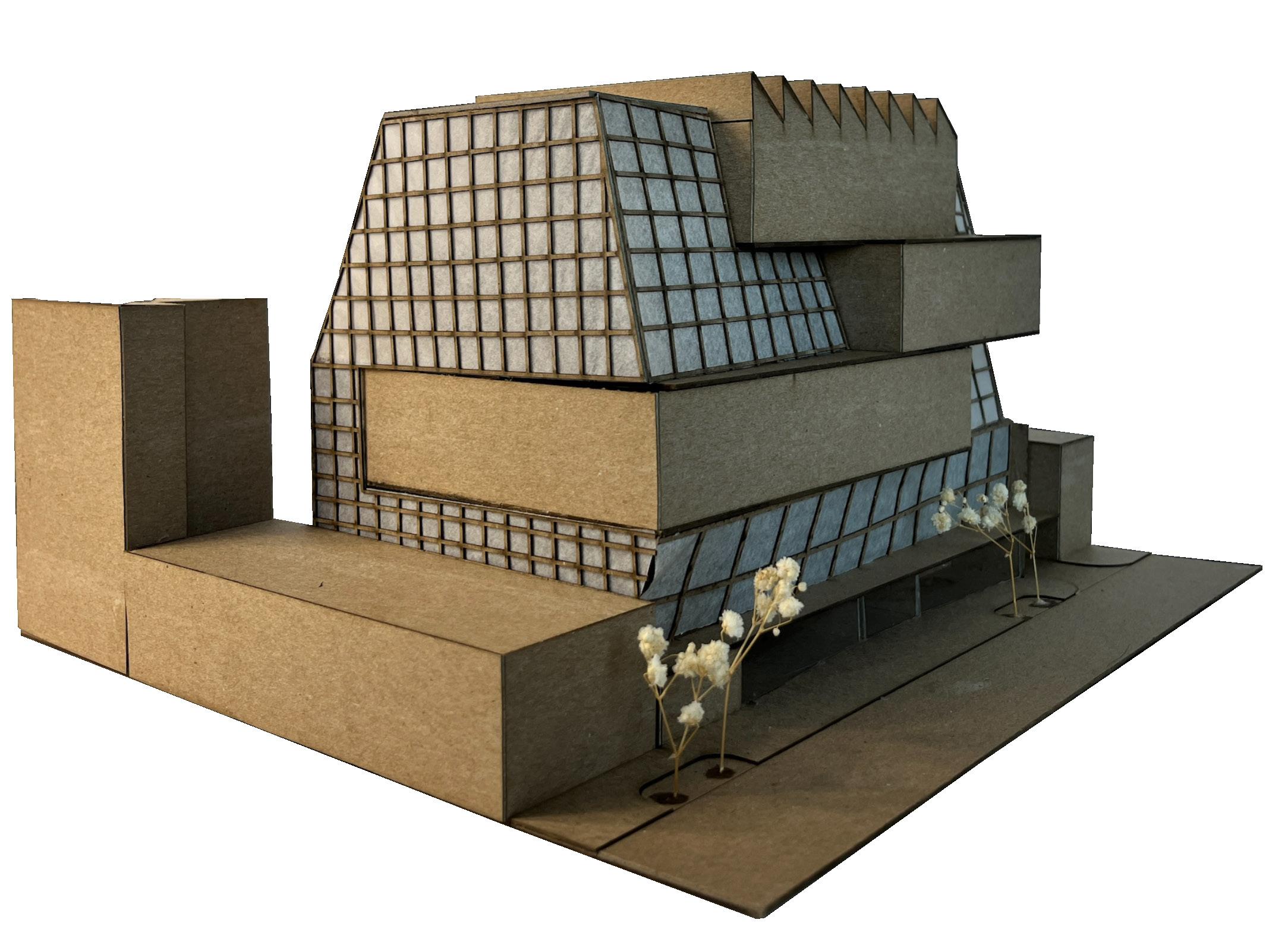
Physical Model (Laser Cutting) | Scale - 1’-0”=1/8”
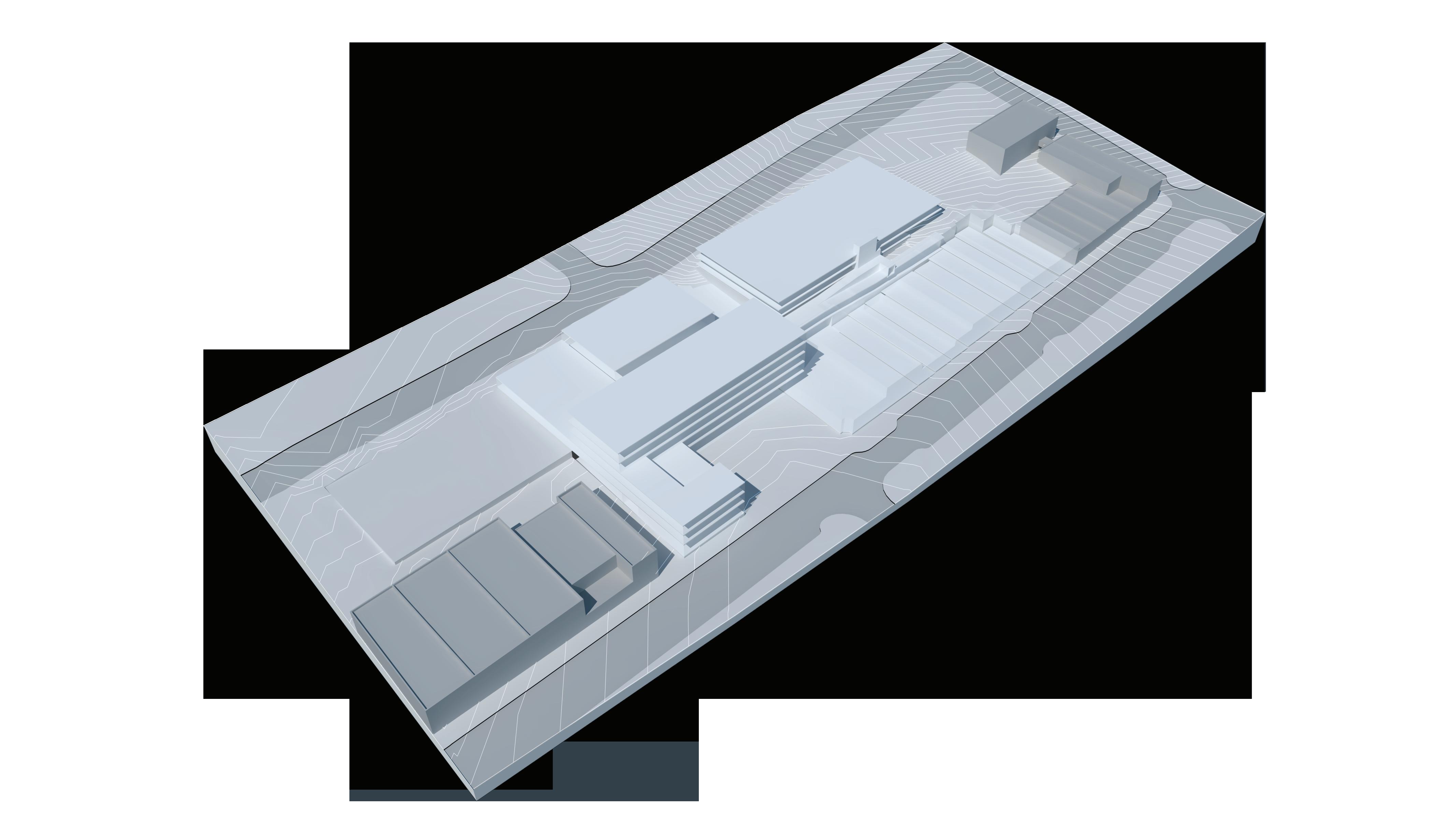
Physical Model (3D Printed)
Scale - 1’-0”=1/32”
VEHICULAR
2nd Floor
4th Floor Plan
5th Floor Plan | N.T.S.
6th Floor Plan | N.T.S.
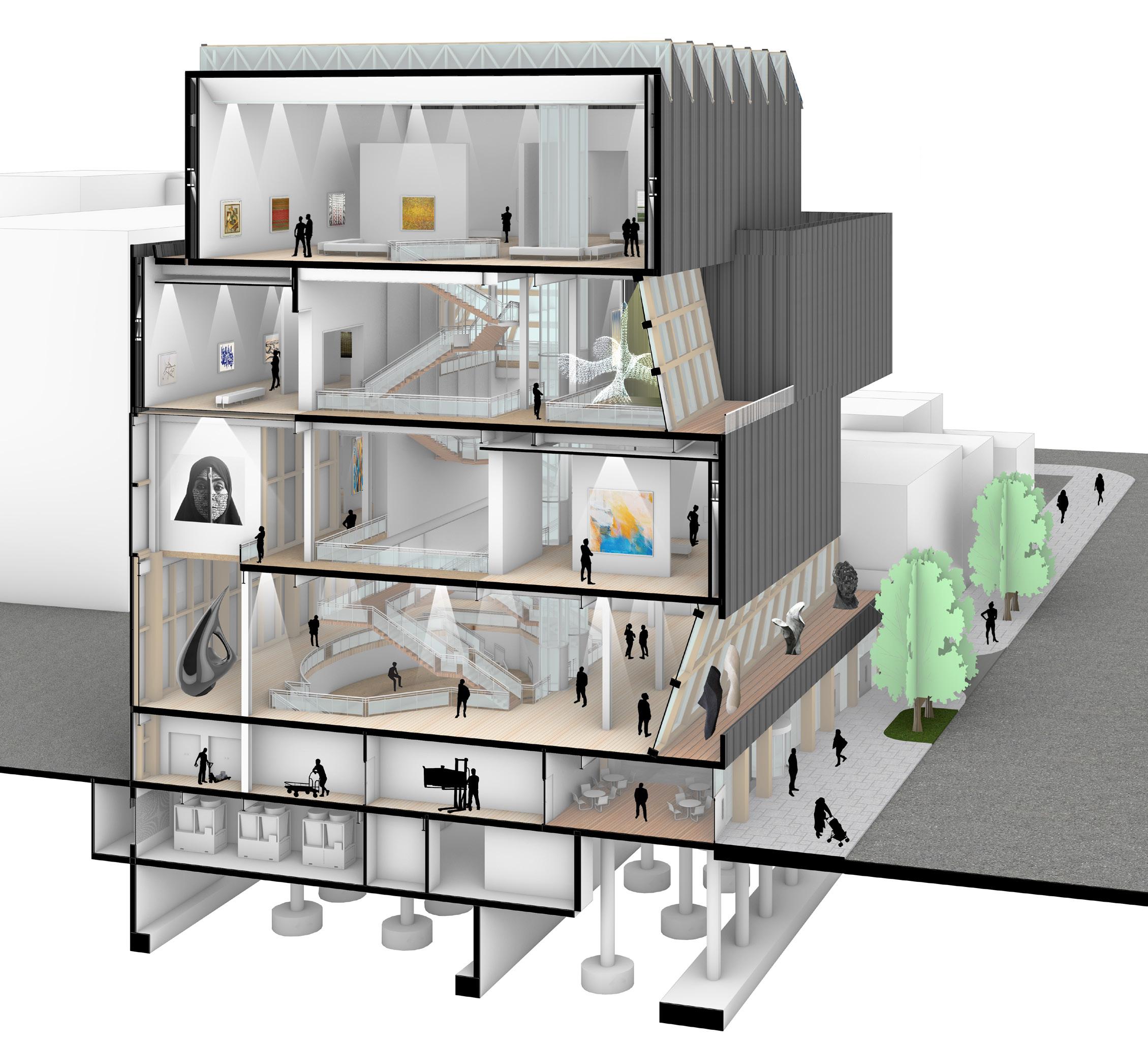
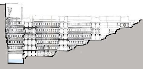
Sectional Isometric View (Lateral) | Envelope Study
Monopan Panels
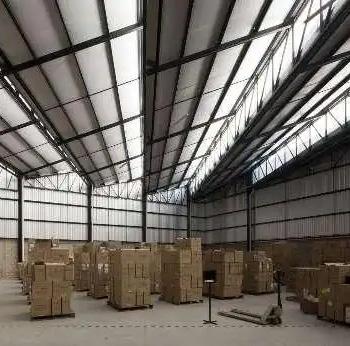
Wooden Framing Zinc Cladding Diffused Skylight North Light Roof
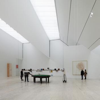
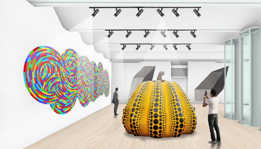
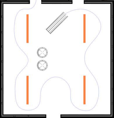
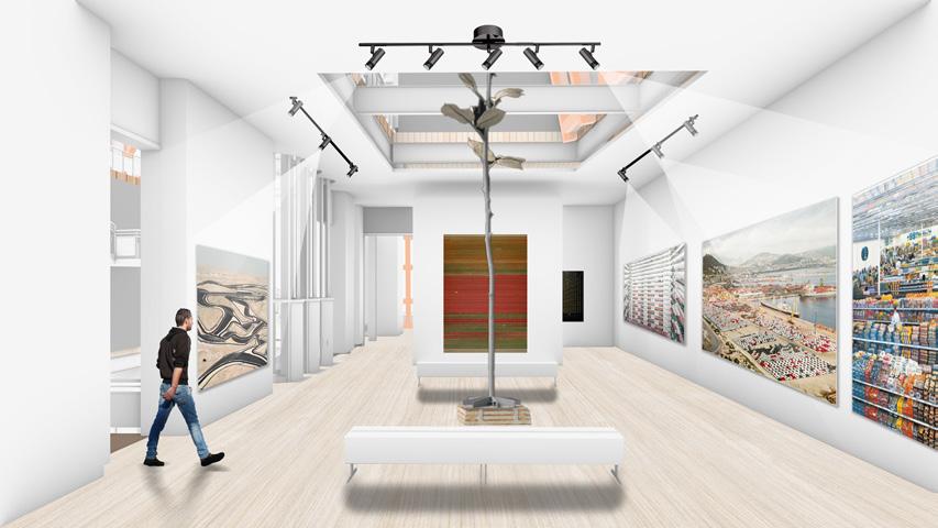
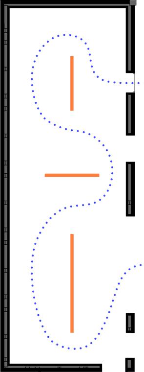
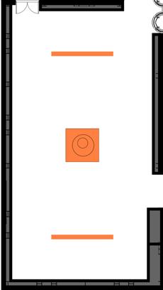
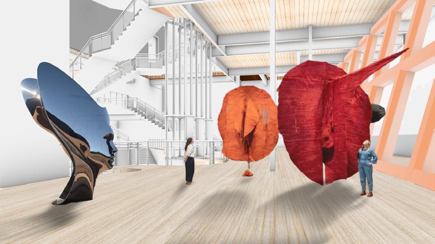
6TH FLOOR THEME GALLERY
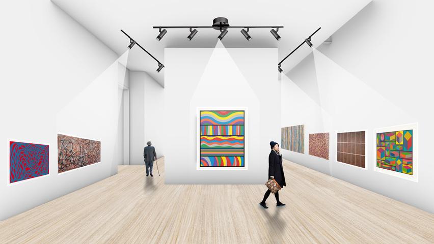
The Gallery serves as the project’s thematic centerpiece, featuring an indirect skylight for soft illumination and an open floor plate for flexible art installations of varying sizes.
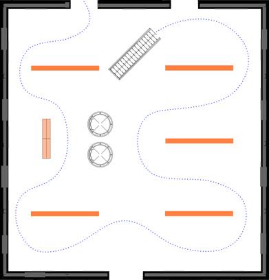
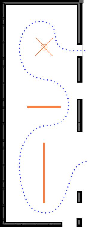
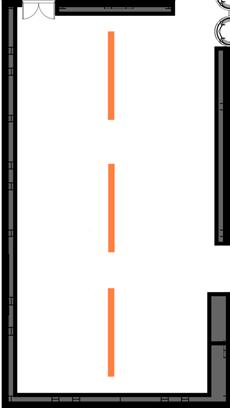
3RD & 4TH FLOOR THEME GALLERY
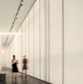
The Fifth Floor Gallery’s rectangular layout and indirect skylight optimize wall-mounted displays with ideal viewing and circulation.
5TH FLOOR GALLERY
The Fifth Floor Gallery’s rectangular layout and indirect skylight optimize wall-mounted displays with ideal viewing and circulation.
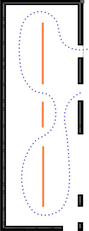
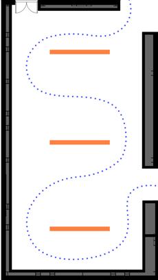
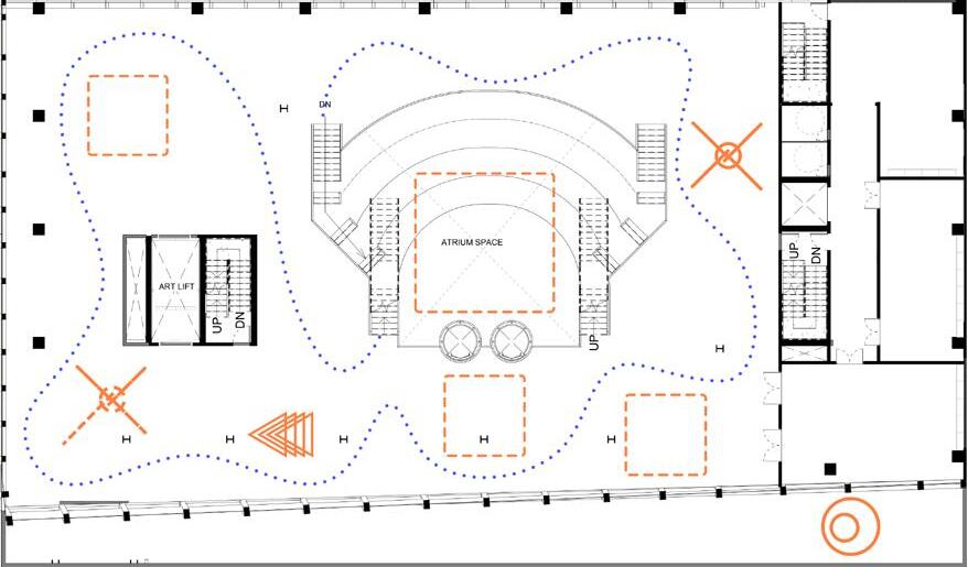
2ND FLOOR SCULPTURE GALLERY
The Second Floor offers a large open plate for sculptures, partially shared with office space and a mezzanine for workstations.
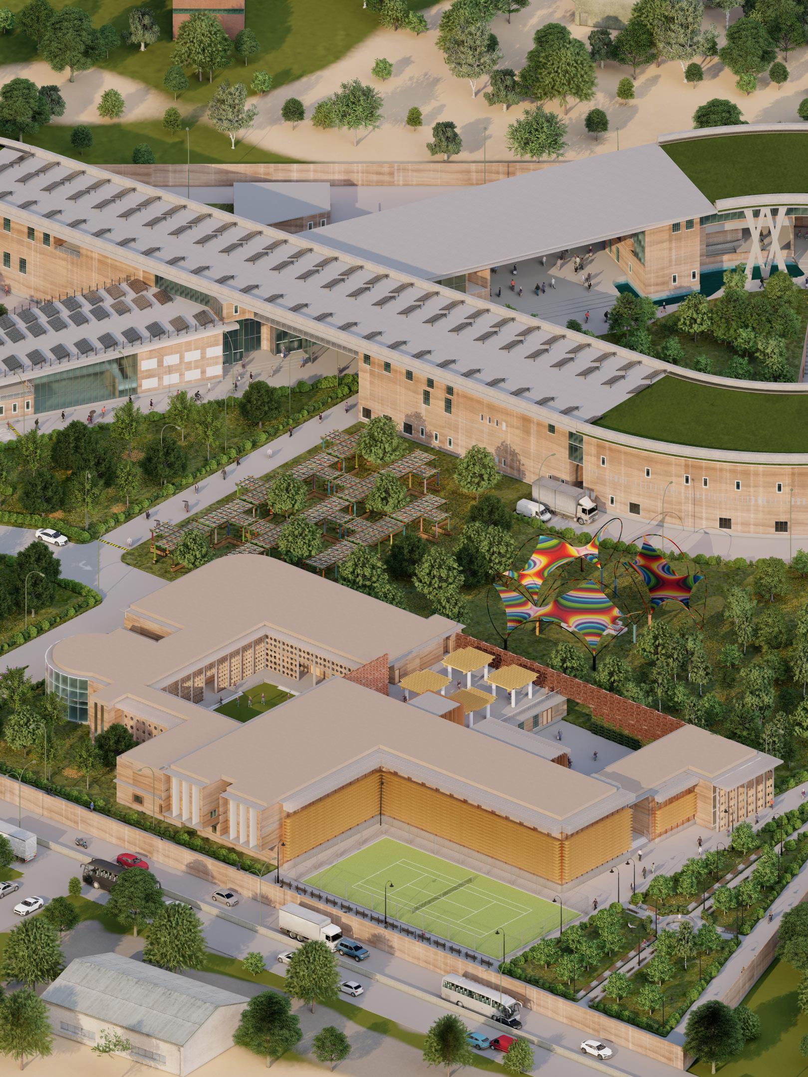
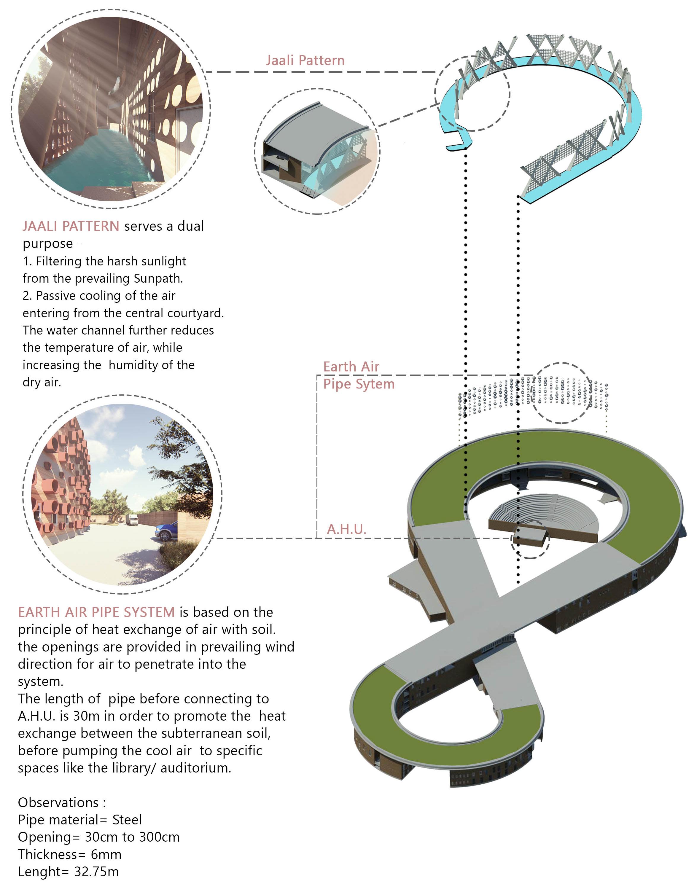
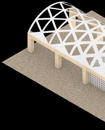
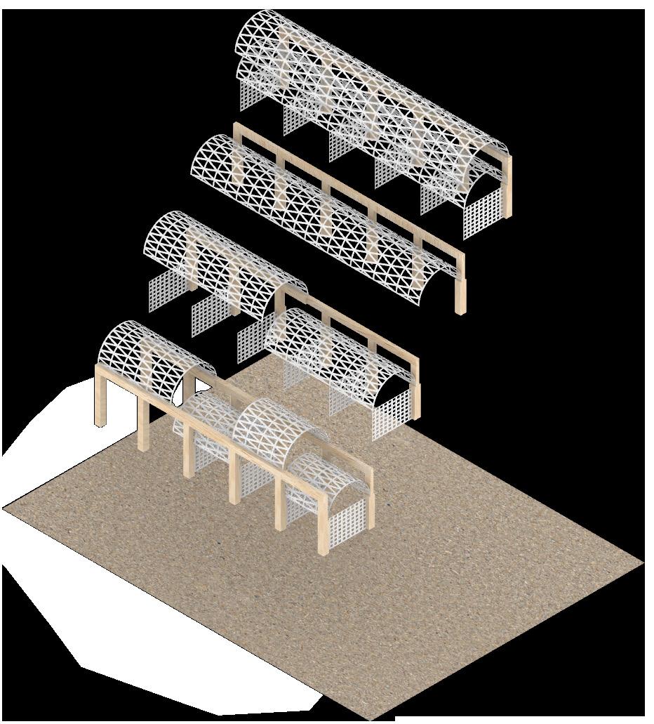
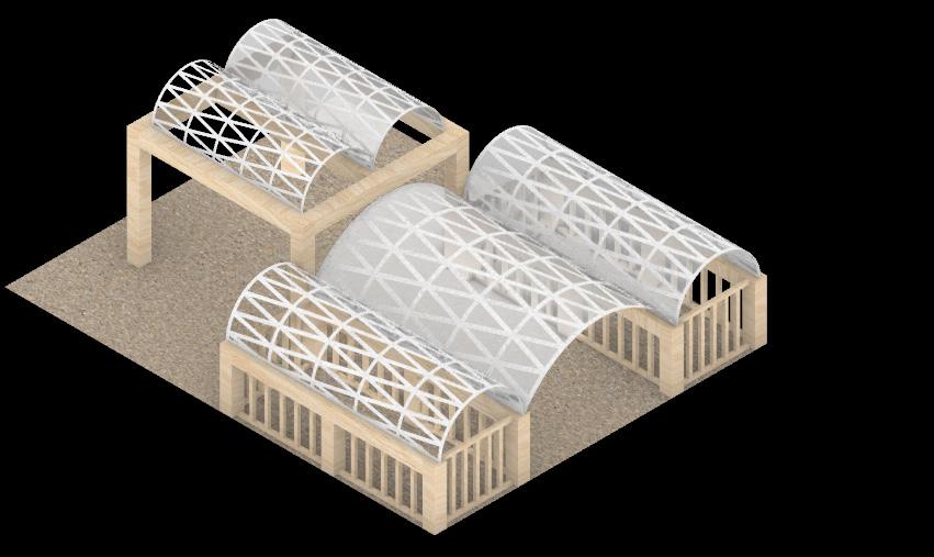
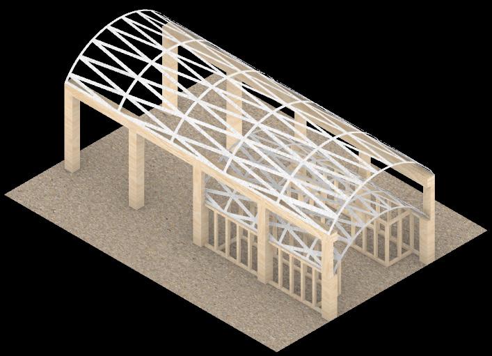
INFINITE BOND:
Rural Community Center & Management Institute
Patan | India
Thesis Project - B.Arch | 2017
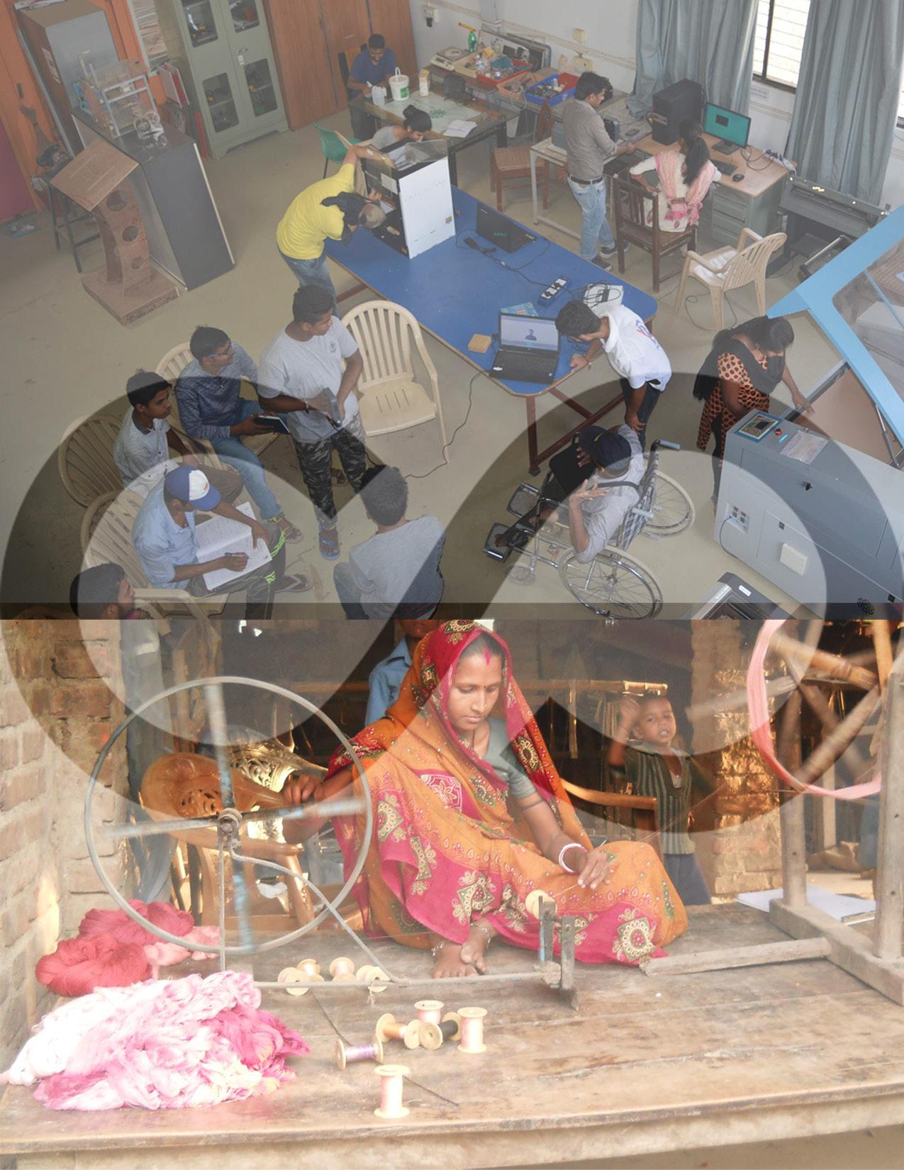
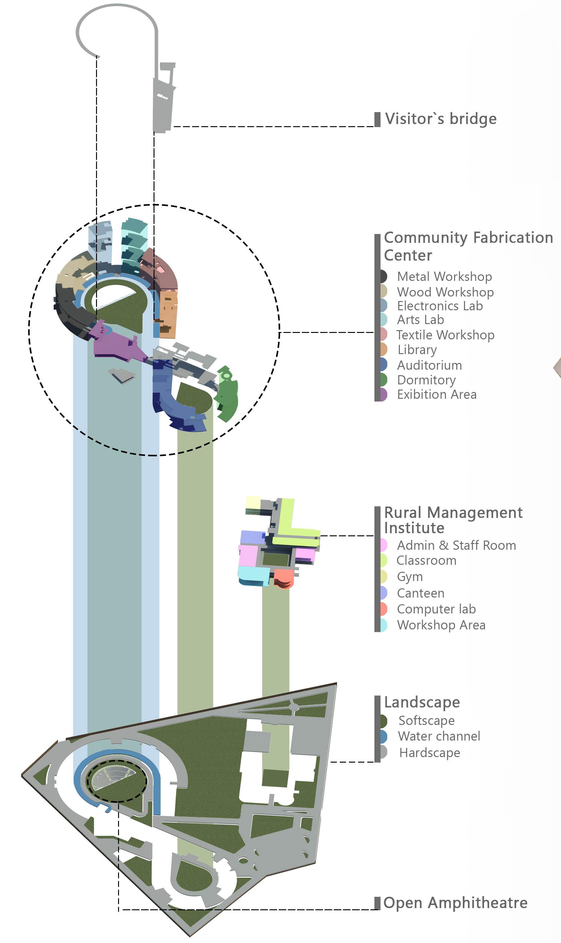
Infinite Bond is an architectural thesis project completed during the final year (5th year) of the Bachelor of Architecture program at the University of Mumbai. The thesis was structured into two semesters, with the first dedicated to research and the second to the design phase. The project seeks to bridge the gap between rural communities and students by establishing a community fabrication center, fostering entrepreneurship across India, and supporting the Make in India initiative, particularly within the country’s manufacturing sector.
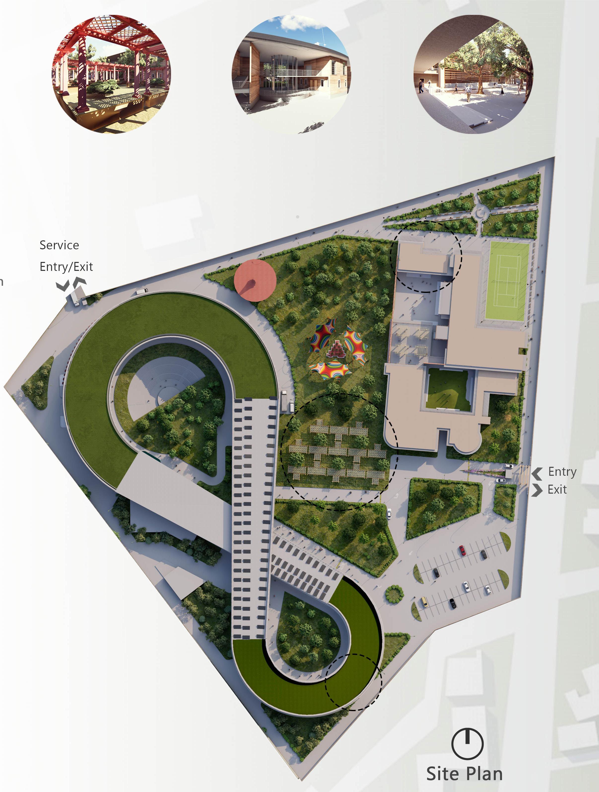
The master plan comprises two primary structures: a community fabrication center and a rural management institute. The selected site had a designated zoning provision for developing an institution that supports rural communities. Patan serves as the central district overseeing 28 rural villages and, consequently, hosts the highest concentration of educational institutions in North Gujarat.
Thesis Chair: Ar. Samir Naik
Working Type: Individual
Softwares: Autocad, Revit, Lumion, Photoshop
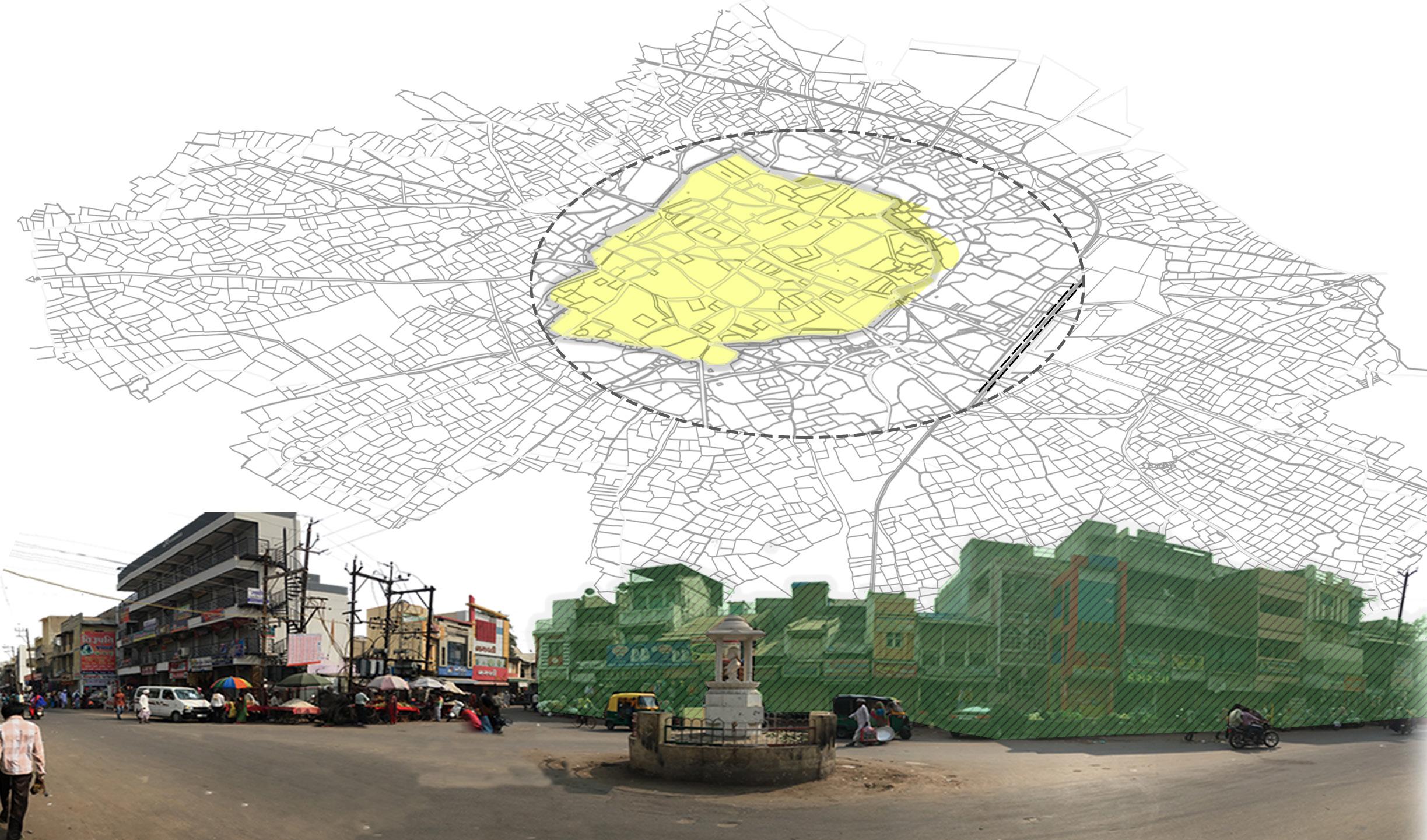
PATAN - CITY CORE
Patan, Gujarat, is a historic city known for its rich cultural heritage. It was the capital of the Solanki dynasty and is home to architectural landmarks like Rani ki Vav, a UNESCO site. The city’s social fabric is shaped by Hinduism, Jainism, and Islam, with Jain temples and Muslim monuments reflecting religious diversity. Patan is famous for Patola silk weaving and celebrates festivals like Navratri and Diwali with vibrant traditions. Its social structure has been influenced by caste and community roles, and the city remains a hub for arts and craftsmanship.
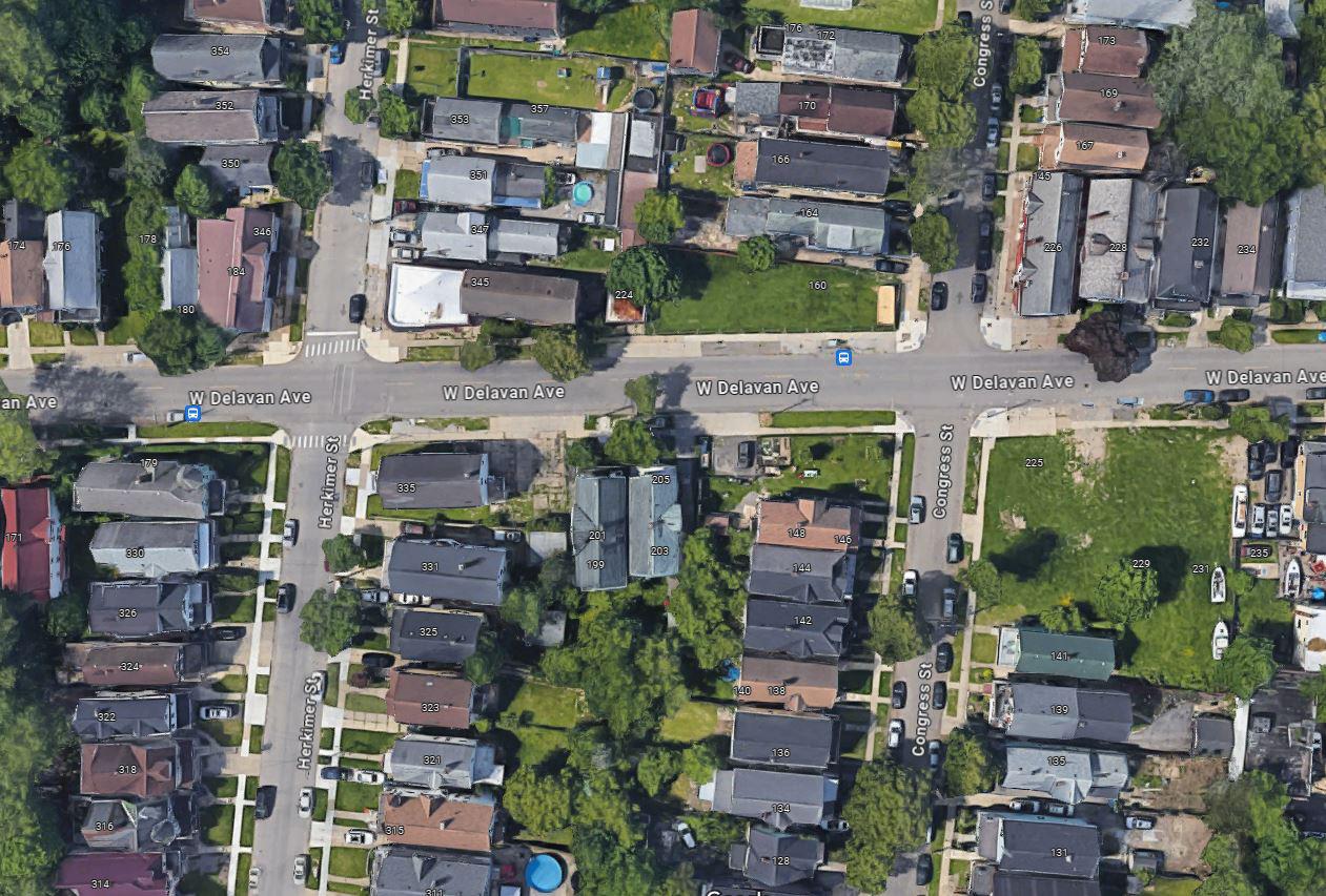
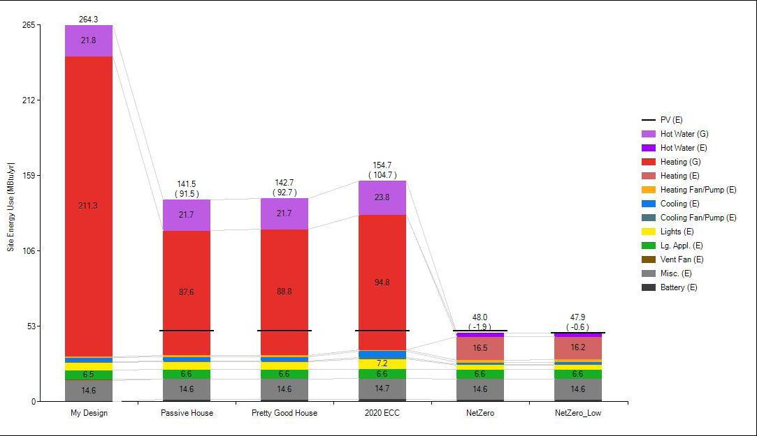
The Synthesis Project focuses on optimizing energy efficiency while ensuring cost-effectiveness for a deteriorating house in Buffalo. My role involved developing a model of the existing house using BeOPT and assisting the team with multiple energy modeling iterations based on Passive House Design, ASHRAE, 2020 ECC, NetZero, and NetZero Low standards. A significant part of my responsibilities included creating approximate wall sections of the existing structure and proposing new wall assemblies best suited for the project.
Faculty: Laura Lubniewski | Nate Heckman
Team Member: Kimia Ghaderian | Pradeep Kondayapalepu |
Sriya Radhekrishnan
Softwares: BeOPT, Autocad, Indesign
Contribution: BeOPT Energy Analysis, Wall Assemblies and Section Details, Site Documentation
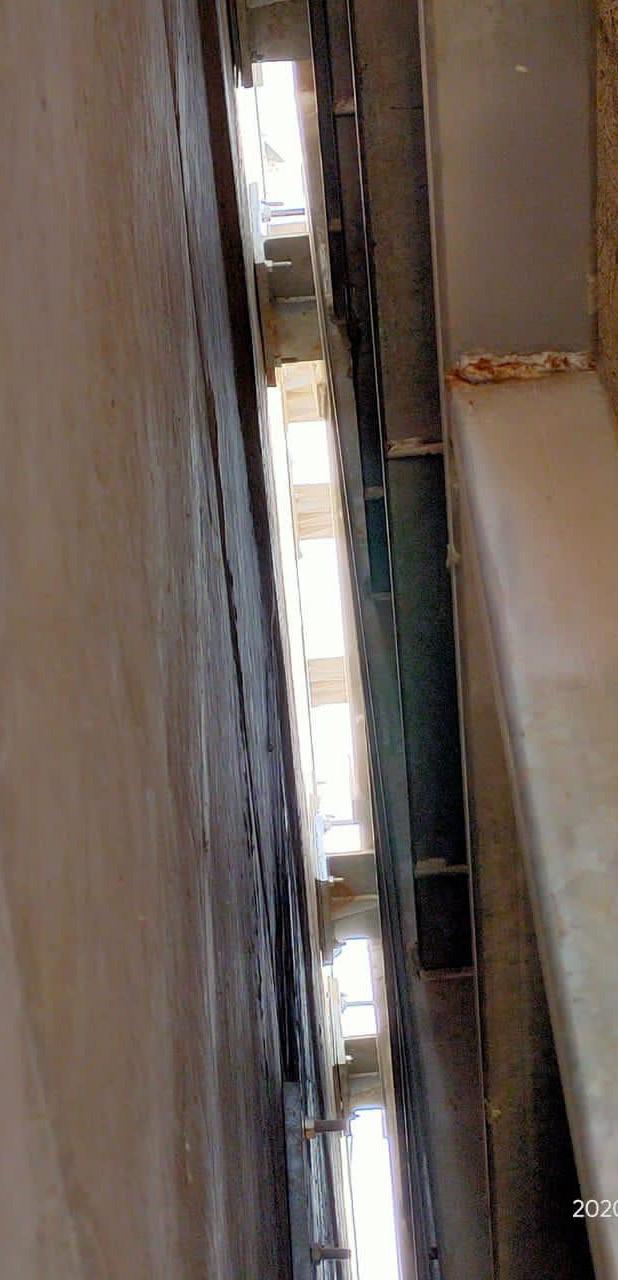
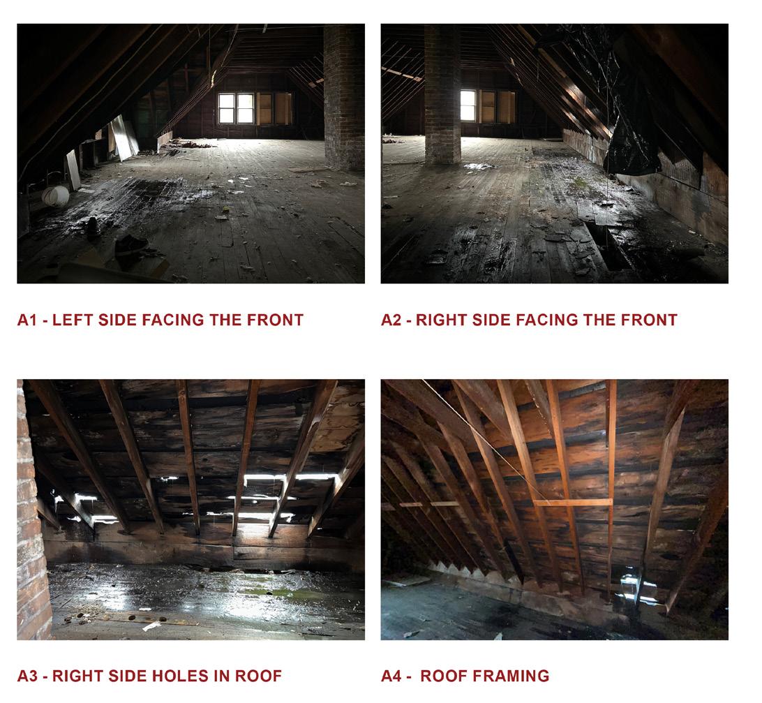
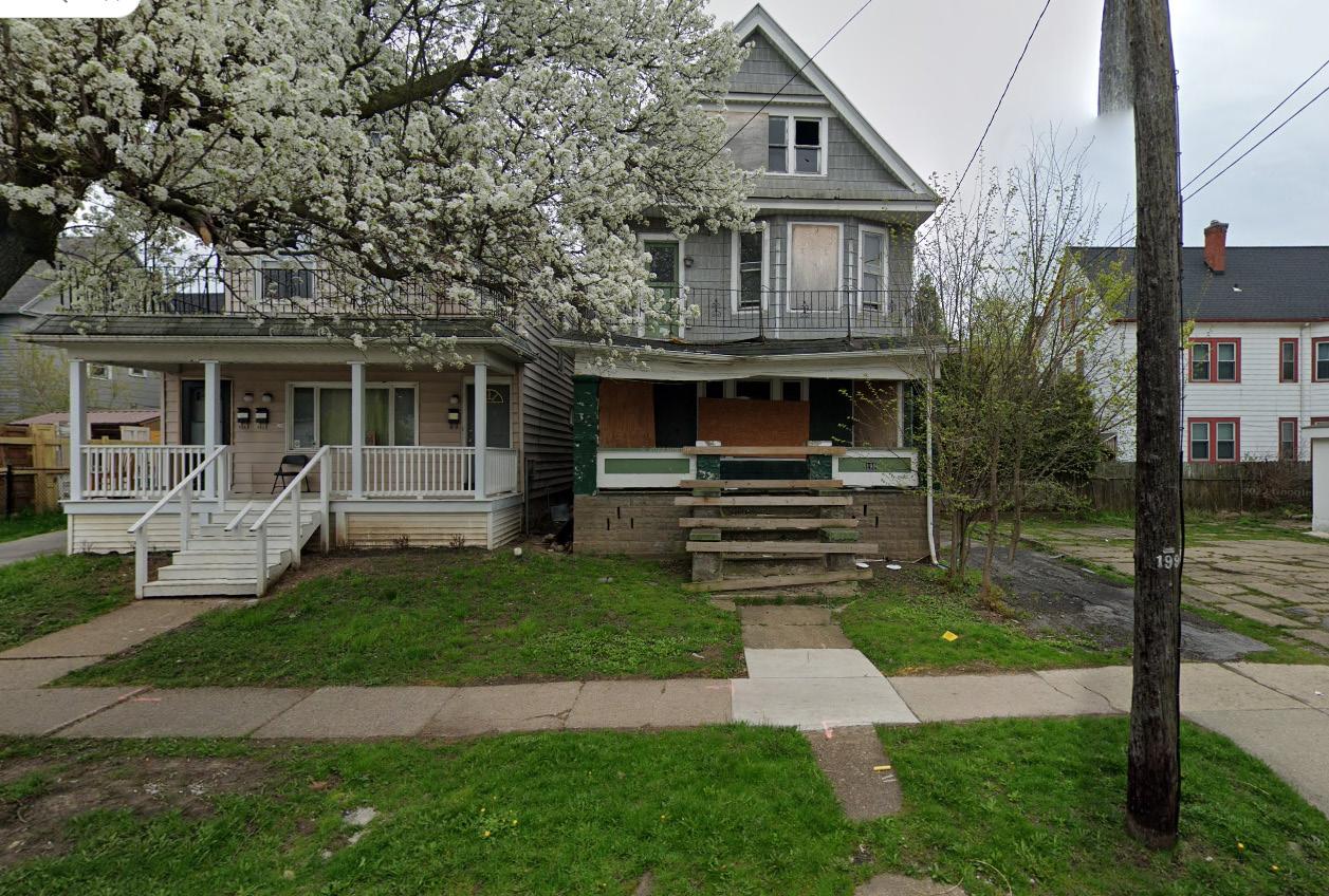
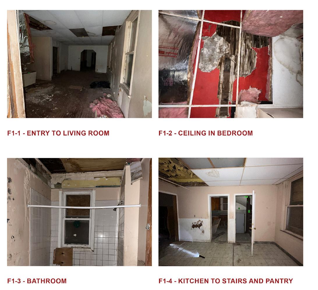
EXISTING BUILDING
EXISTING BUILDING
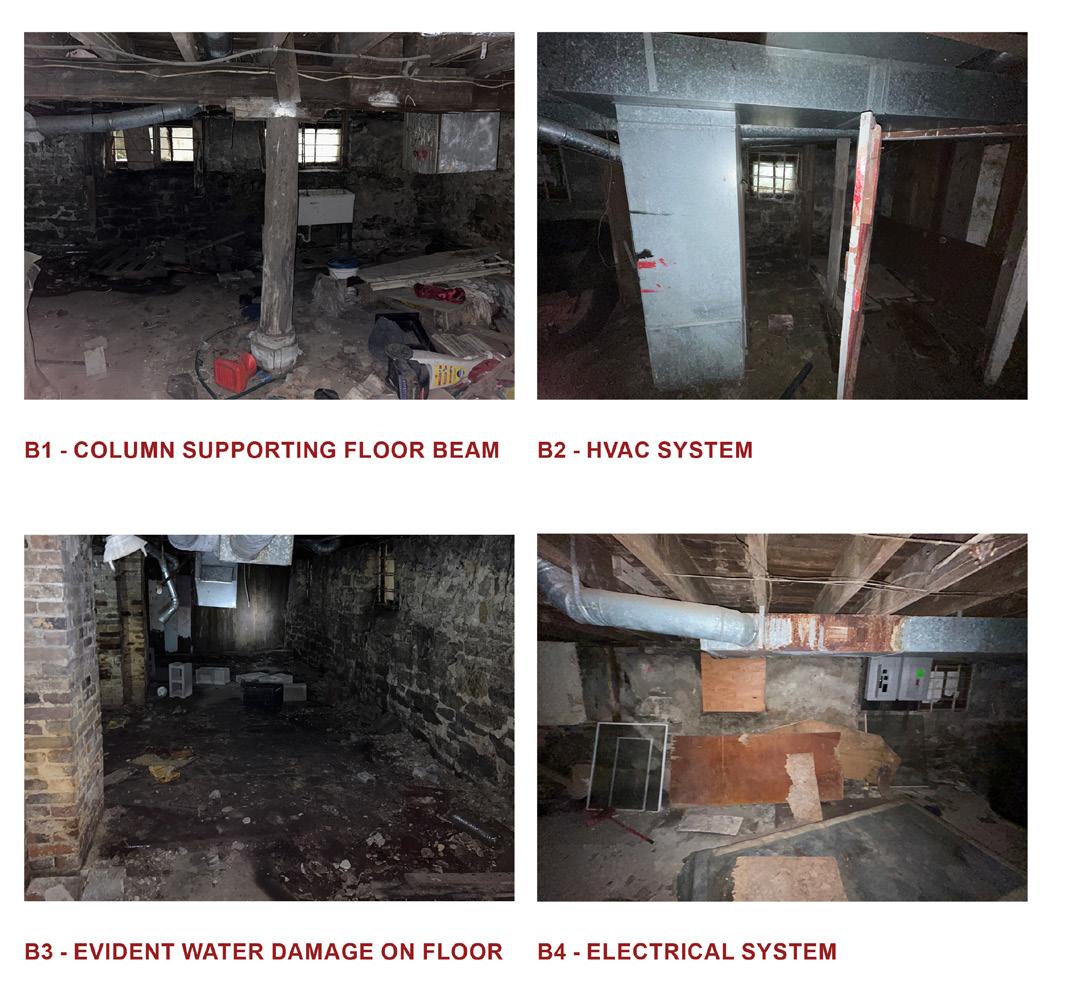
The roof of the porch is sagging greatly potentially due to water damage or the foundation sinking. There is also evidence of water damage on the floor and with some of the walls that are crumbling for the basement.
The roof of the porch is sagging greatly potentially due to water damage or the foundation sinking. There is also evidence of water damage on the floor and with some of the walls that are crumbling for the basement.
The drop ceiling and insulation have fallen in some areas, revealing the original wood and plaster ceiling underneath in the first floor.
The damage to the walls is more extreme on the second floor.Pails is peeling in the corners of several rooms and in those same corners the floors have begun to rot away. Once again the drop ceiling is damaged and reveals the original wood and plaster ceiling.
The damage to the walls is more extreme on the second floor.Pails is peeling in the corners of several rooms and in those same corners the floors have begun to rot away. Once again the drop ceiling is damaged and reveals the original wood and plaster ceiling.
The drop ceiling and insulation have fallen in some areas, revealing the original wood and plaster ceiling underneath in the first floor.
The damage to the walls is
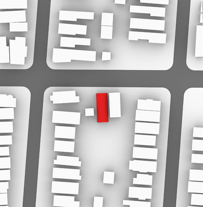
Adjacent houses - 1 Right Side
Adjacent houses - 4' Setback
SIMULATION COMPARISON ACROSS VARIOUS SITUATIONS
SITE CONTEXT
EXISTING BUILDING INFORMATION
Trees - 3 Nos
Vegetation - Trees on South Side
EXISTING BUILDING DETAILED SECTION
HOUSE OWNER INFORMATION
ZERO TOOL ANALYSIS
Driveway - Driveway on NW side
Garage observed - Na
PROPOSED BUILDING UPDATION AND THERMAL PROFILE
PROPOSED BUILDING UPDATION SECTION
BeOPT SIMULATION ACROSS SCENERIOS
PRODUCTS INFORMATION
CO2e EMISSIONS COMPARISON
PASSIVE SURVIVABILITY TEST
Since our client would like to produce maximum energy on site. Hence, we propose to change the pitched roof to a flat roof. Through this action, we will have space to install photovoltair cells to capture solar energy.
Porch overhang - 6'9" North Side
Since our client would like to produce maximum energy on site. Hence, we propose to change the pitched roof to a flat roof. Through this action, we will have space to install photovoltair cells to capture solar energy.
We realise through our Beopt modelling, that we are able to reach net zero energy consumption.
We realise through our Beopt modelling, that we are able to reach net zero energy consumption.
ANNUALIZED UTILITY BILLS
BIBLIGRAPHY
BEOPT SIMULATION COMPARISON ACROSS VARIOUS SITUATIONS
ASPHALT SHINGLE RAFTER 2"X6" 16"O.C.
SOFFIT VENT RIGID INSULATION R10
GUTTER
2"X6" 16"O.C.
1 2" GYP BOARD
WOOL INSULATION (R24)
WOODEN SHINGLE
1 4" OSB BOARD
EXTERIOR INTERIOR
EXTERIOR
ROOF SECTION DETAIL
ROOF SECTION DETAIL
SCALE: N/A
SCALE: N/A
2ND FLR
2ND FLR
EXTERIOR INTERIOR
WOOL INSULATION (R24)
4" OSB BOARD WOODEN SHINGLE
RIGID INSULATION R10
WOODEN SHINGLE
EXTERIOR INTERIOR
RIGID INSULATION
COVER BOARD
R10
MINERAL WOOL INSULATION (R24)
1 2" WOODEN SUBFLOOR
2"X8" WOODEN STUDS 16" O.C.
AIR VENT
1 4 OSB BOARD
EXTERIOR INTERIOR
FLOORING SECTION DETAIL
SCALE: N/A
SCALE: N/A
EXTERIOR INTERIOR
1 2" GYP BOARD MINERAL WOOL INSULATION (R24)
2"X8" WOODEN STUDS 16" O.C.
1 2" GYP BOARD
FLOORING SECTION DETAIL
CONTINUOUS BEAD OF ADHESIVE
CONTINUOUS BEAD OF ADHESIVE
CONTINUOUS BEAD OF SEALANT
CONTINUOUS BEAD OF SEALANT
ENGINEERED FLOOR
ENGINEERED FLOOR
CAVITY INSULATION
EXTERIOR INTERIOR
FOUNDATION DAMP PROOFING TO FINISH GRADE STONE FOUNDATION WALL CONCRETE SLAB RIGID INSULATION
GRADE/BELOW GRADE DETAIL
SCALE: N/A
GRADE/BELOW GRADE DETAIL
SCALE: N/A
SHEATHING
ROOF SECTION DETAIL
SCALE: N/A
ROOF SECTION DETAIL
SCALE: N/A
TAPERED RIGID INSULATION (R- 30 + 19) 1 4" SLOPE WITH MIN 7" INSULATION
CLOSED CELL SPRAY FOAM INSULATION
ENGINEERED JOIST METAL COPING SELF ADHERED MEMBRANE
EXTERIOR INTERIOR
EXTERIOR INTERIOR 2ND FLR
EXTERIOR INTERIOR 2ND FLR
FLOORING SECTION DETAIL
SCALE: N/A
FLOORING SECTION DETAIL
SCALE: N/A
EXTERIOR INTERIOR
GRADE/BELOW GRADE DETAIL
SCALE: N/A
08.2
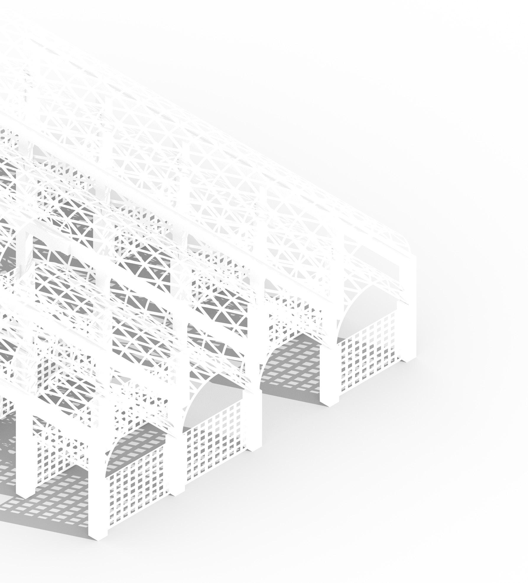
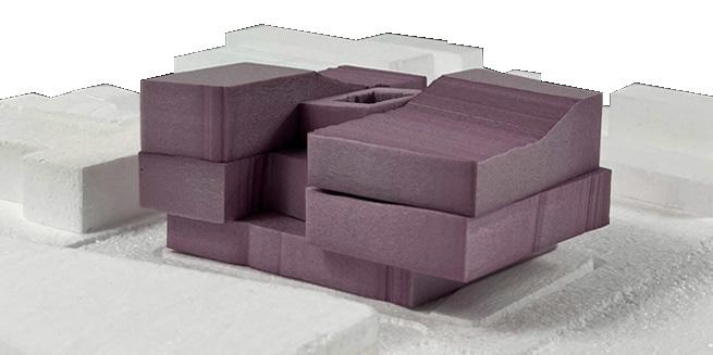
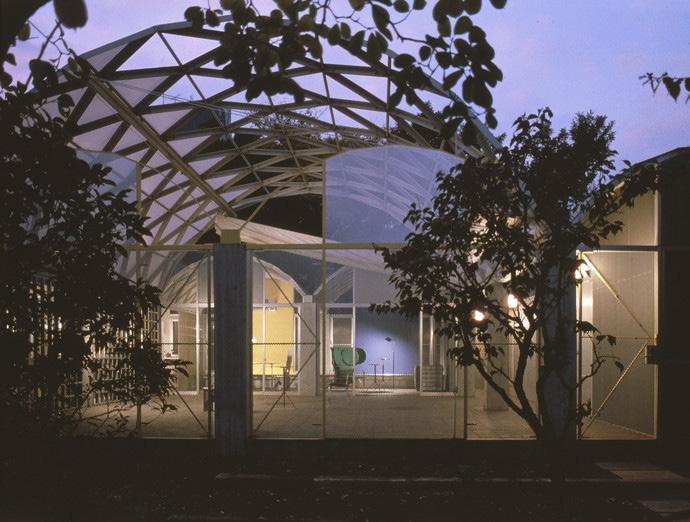
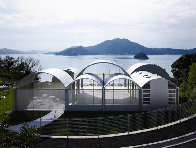
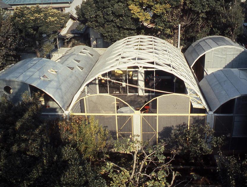
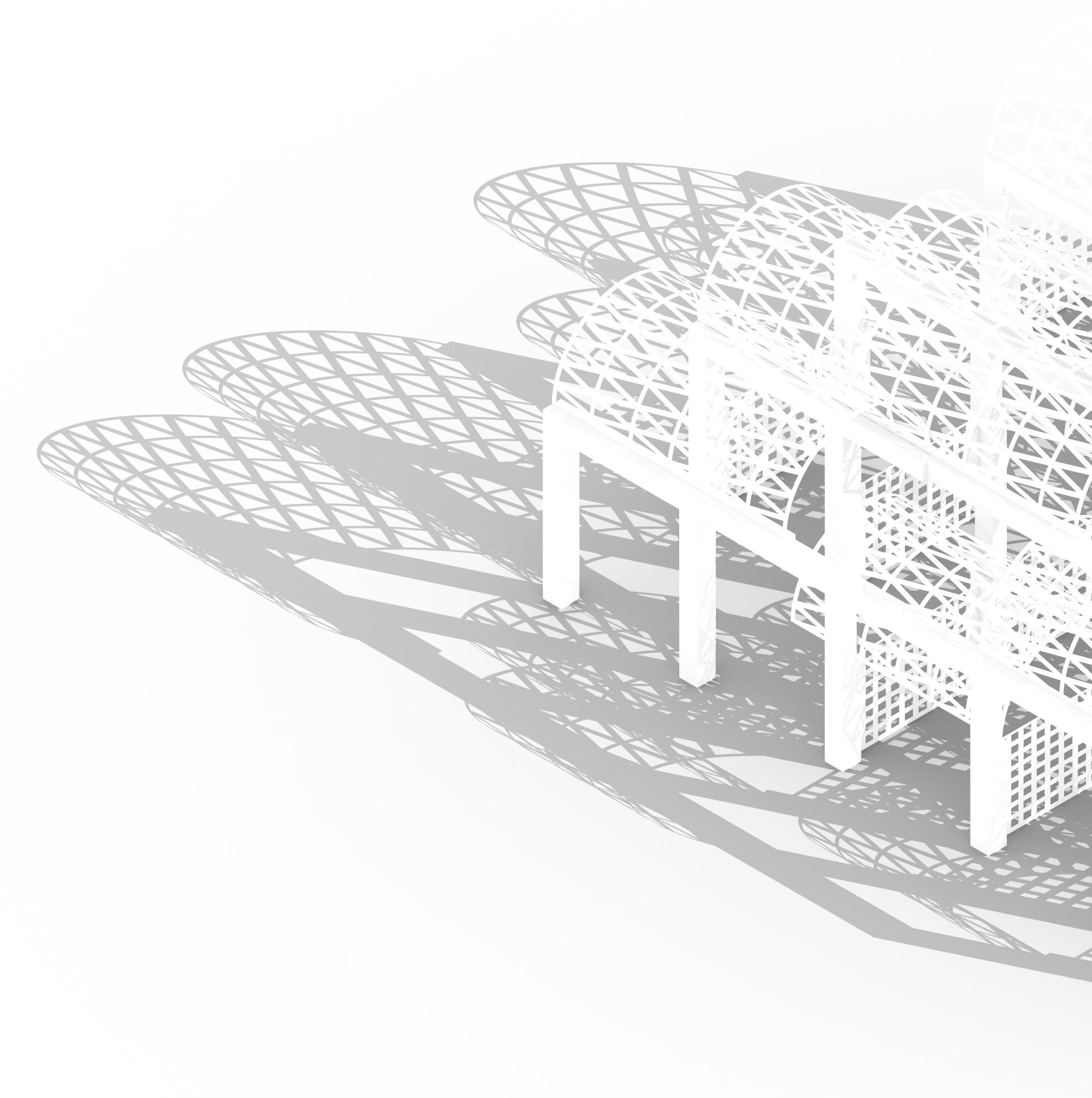
SYMBIOTIC SANCTUM: Toyo Ito`s Poetics Through the Lens of Bloodchild
ARC 632 - Material Culture
Academic Project - M.Arch | 2024
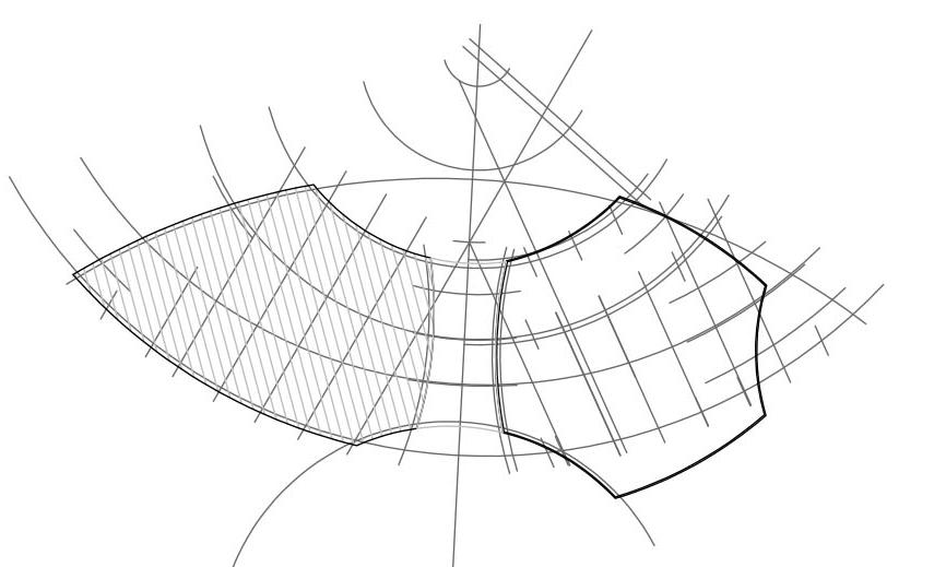
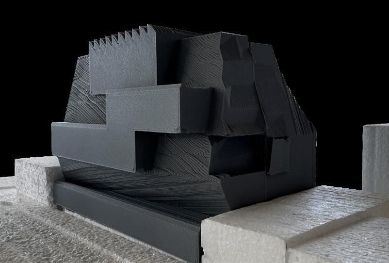
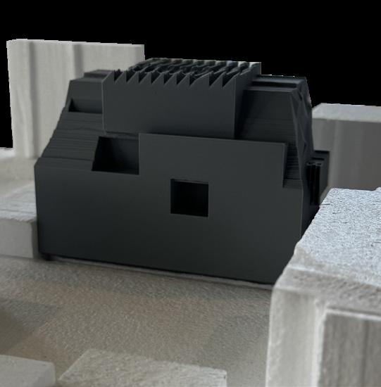
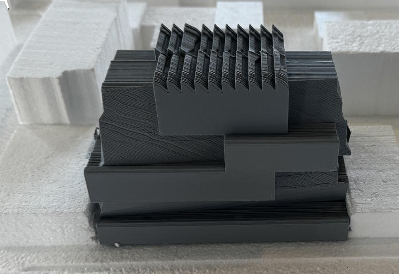
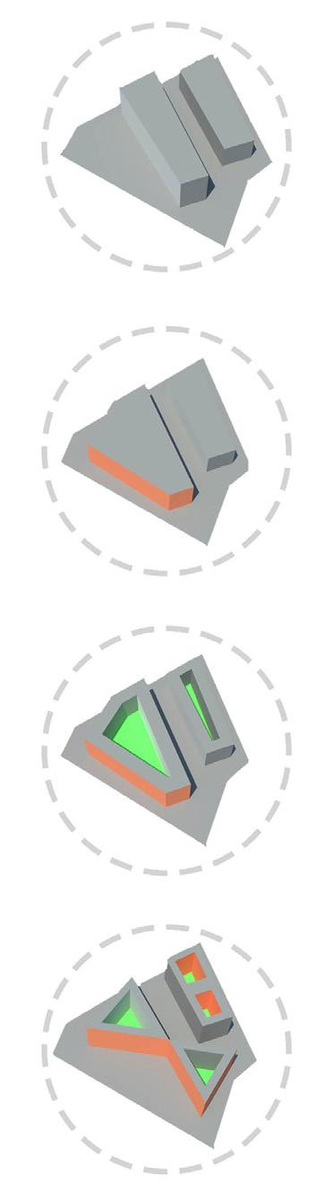
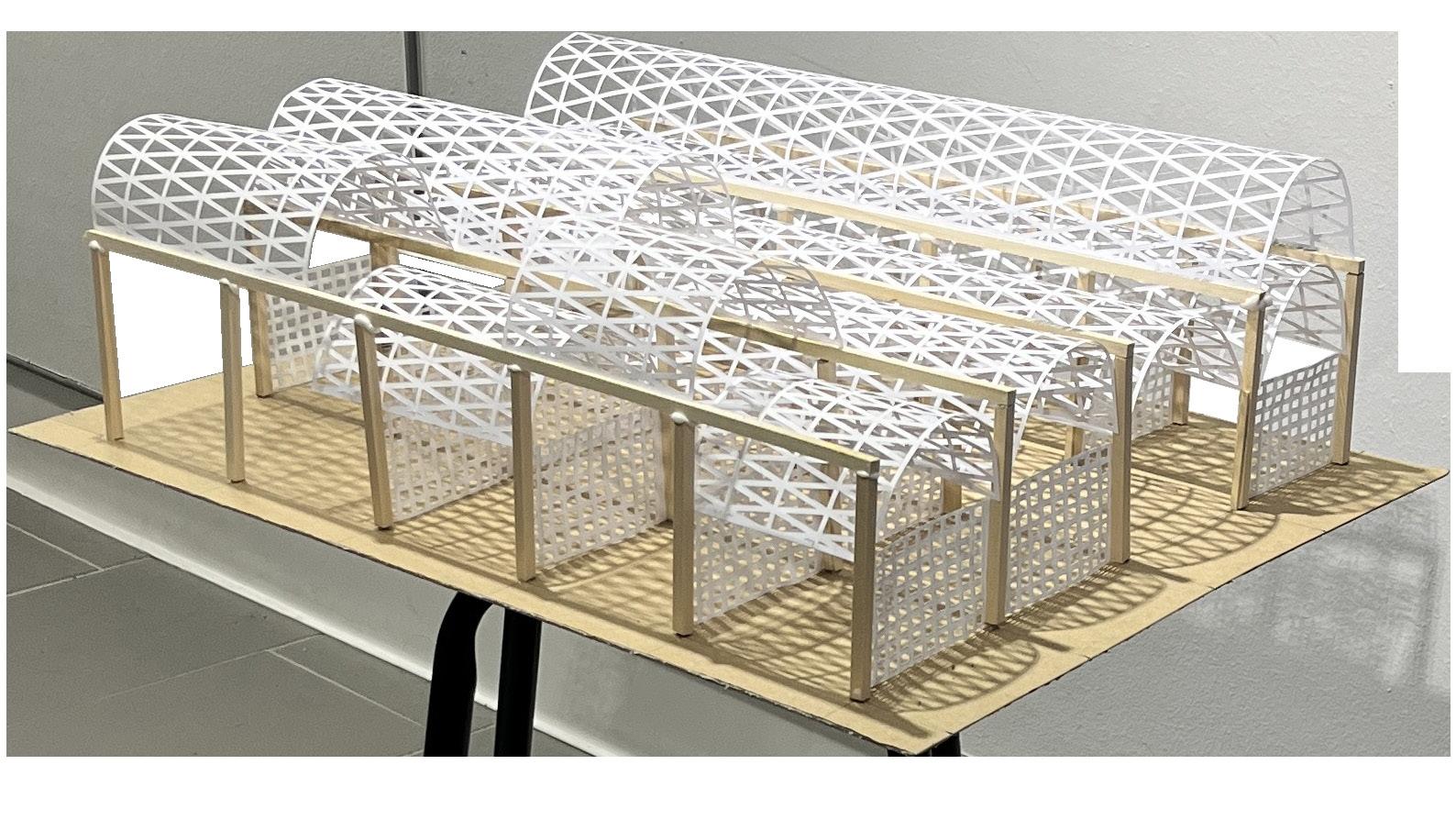
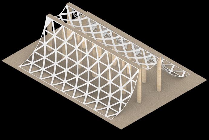
Symbiotic Sanctum is an architectural exploration that merges elements from Octavia E. Butler’s Bloodchild with the material tectonics of Toyo Ito’s Silver Hut through intensive model-making. The process involved analyzing Silver Hut’s construction, redefining its relationship with the ground, and extracting spatial qualities from Bloodchild to re-imagine its tectonics. Physical models, crafted from Bristol paper, a chipboard base, and wooden dowels, translated these ideas into an immersive architectural experience, blending speculative fiction with material expression.
Faculty: Tiffany Xu
Working Type: Individual
Softwares: Rhino, Grasshopper, Autocad
Hollow Sticks
Stack
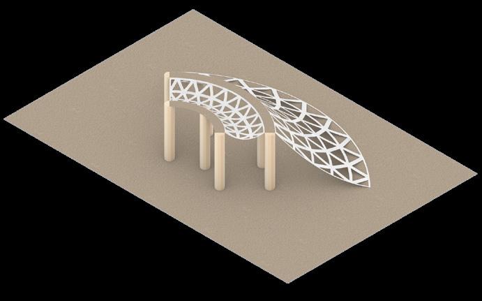
Redefining Material Tectonics
Phase 1 involved identifying and investigating material tectonics, focusing on reinterpretation to establish new relationships between linear elements, layered assemblies, and voids.
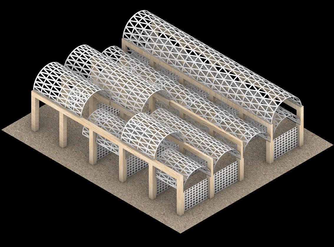
Physical Manifestation
Phase 2 focused on constructing a physical model derived from the geometric explorations in Phase 1. Consequently, the initial weeks were dedicated to restricting model development to 2D techniques.
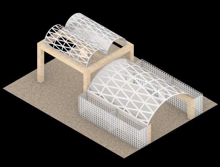
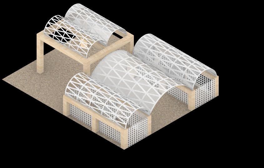
Symbiotic Sanctum
Phase 3 was divided into two parts. The first part involved analyzing Bloodchild to identify and highlight spatial qualities described in the text. The second part focused on translating these spatial characteristics into an experiential space. The relationships developed in Phase 2 were further refined by integrating them with the architectural precedent of Toyo Ito.