6 minute read
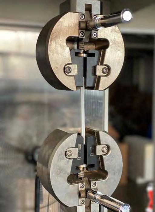
Material Test

//The individual thickness of the /3D printed samples is not uniform and the maximum tensile load varies from 400N to 1000N. The design should not be based on the 850N provided by the material supplier. The design should control the tensile force in a single bar to not exceed 400N. The design should control the tensile for the bar at 25MPA 400N deformation of about 4mm.
Advertisement
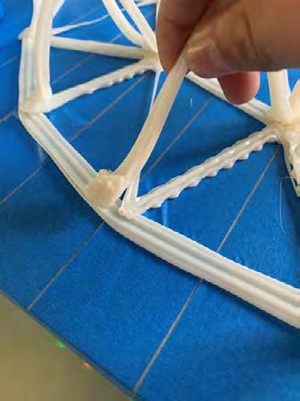
//Printing base found after playing three circles to go to the middle curve there is a collision phenomenon caused by the base and the plane paste is not firm
//Printing of the base was OK, but it was found that the beginning and the end of the curve of the column were not firmly pasted.
//The first part of the column does not stick
//The chassis will shake.
// height difference between the second and third layers when going round, resulting in badly shaped direct interference dots
// The first layer is a little short in time, resulting in poor adhesion and loosening of the material.
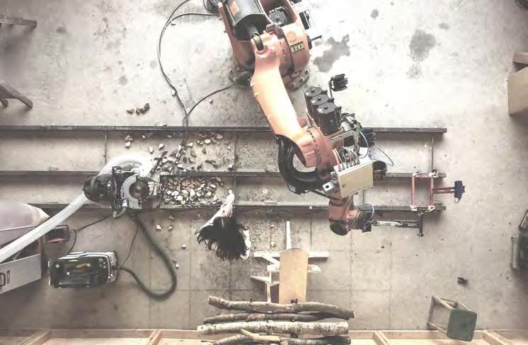
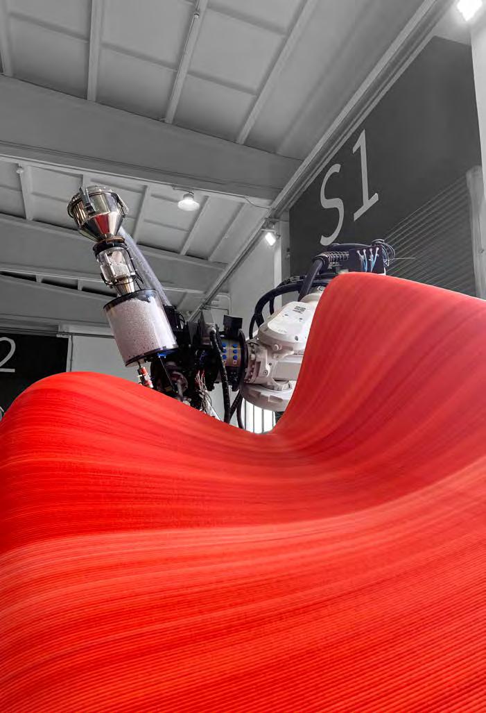
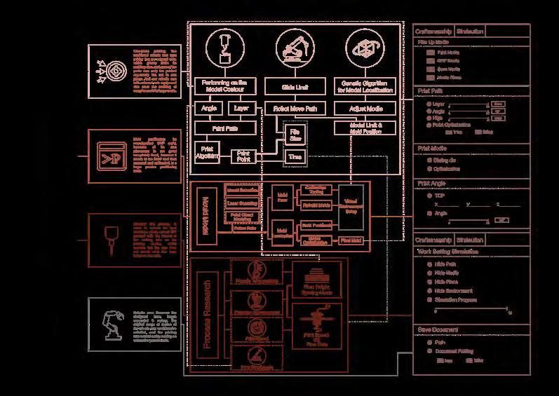
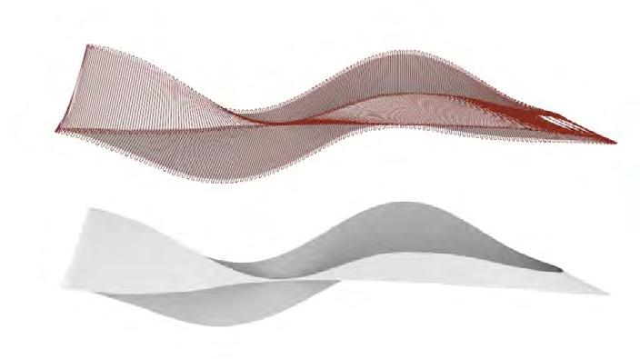
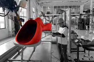
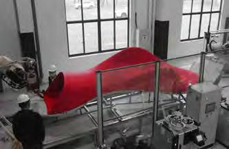
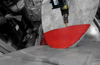
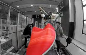
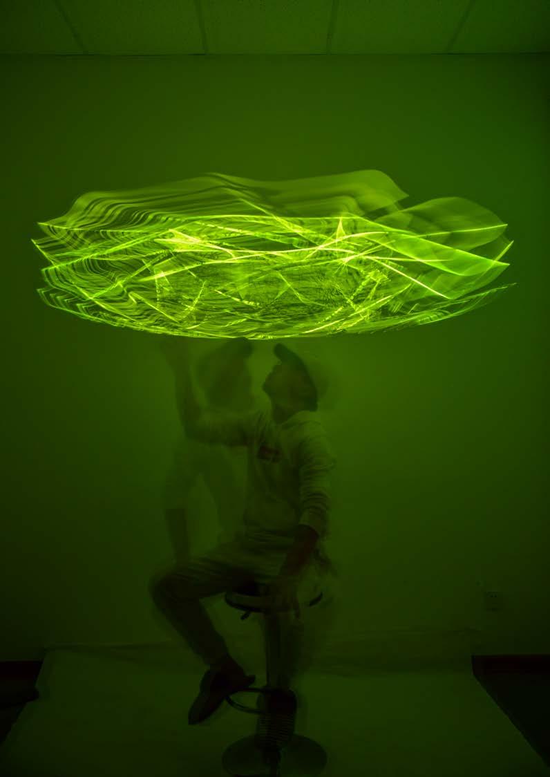
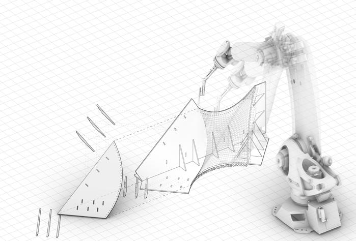
Due to the limitation of the working range of the robot arm, we divide the entire form into different small blocks in the whole program, first through the program to generate the print path of each block, and then choose different print settings for the print path, combined with the characteristics of the material, we get the most effective tool path at present
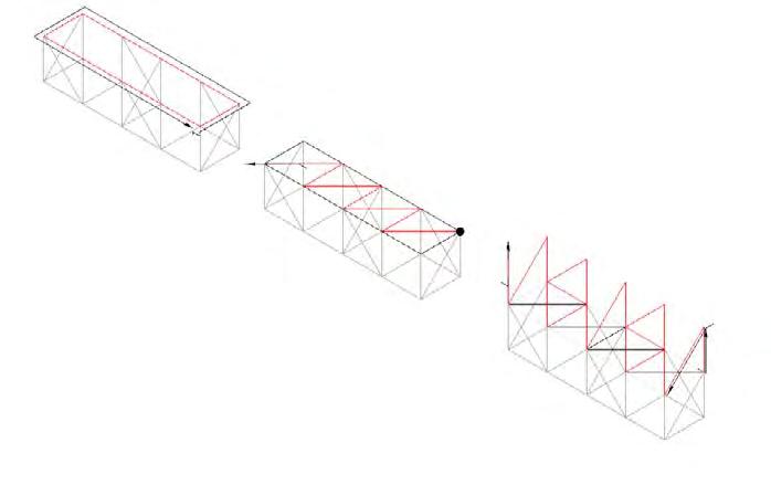
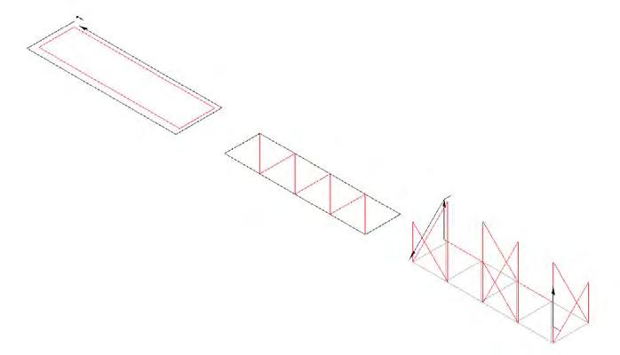
Tool Path
Print Path Generation
The project will be in Shanghai for two years and will interact well with the surrounding residents as an art installation
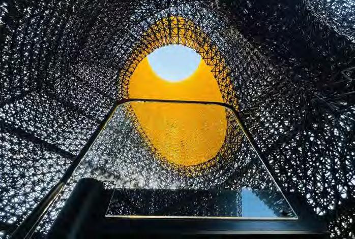
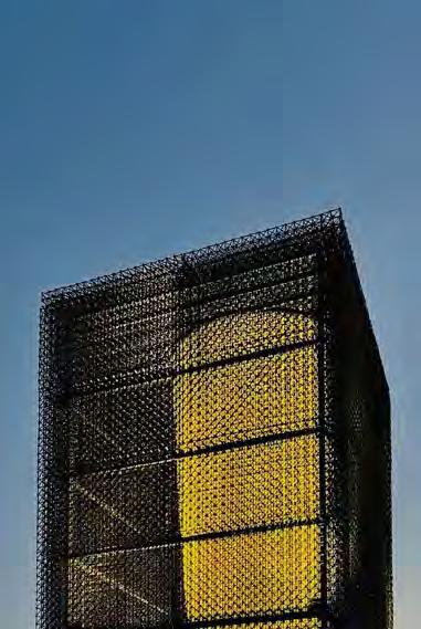
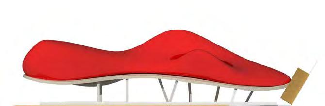
Yangzi River Urabn Front Desk Printing
Professional Work / Team Work 2021.1-2021.3, 2 months
Personal Contribution: concept, model, drawing, fabrication Work in ROBOTICPLUS.AI (Shanghai) Co., Ltd
This project is to encounter during the period of internship, I mainly several interns are responsible for testing and production by us. Changjiang Front Desk Printing is a practical demonstration of the control and development technology of 3D printing technology for complex forms of Robotics Company. The project has been tested for several months and improved in process and algorithm. And you end up with a perfect result.
At the same time, the technology of integrated printing of curved surface molds is also the first attempt in the world, and it has also applied for a national patent; the project team has been exposed to the tilt printing technology from the beginning, gradually improved the printing parameters and the setting of the points, and completed the integrated printing molding, which solved the problem of nozzle equipment, movement trajectory and A summary of the experience of forming textures, a variety of printing methods were discussed at the same time in the project, the advantages and disadvantages of different printing methods, and the feasibility of technical improvement methods were studied.
Note: This project, complete in ROBOTICPLUS.AI (Shanghai) Co., Ltd, Shanghai, China.
GRP Mold Lamination Calibration
Point Cloud Scanning
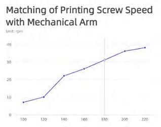
Speed Relationship Study
According to the speed stable form of the actual test, we complete the gradual setting of the speed control of the manipulator, and use the advanced morphological algorithm to adjust the speed proportion gradually according to the single circle length
After the actual test, it is found that if the nozzle is 2 mm away from the mold, it is equivalent to an additional 2 mm of material extrusion die, so as to achieve the purpose of precise shape control
Slice Tilt Angle Research
Robot speed: 1.5-2 cm/s layer high: 2.5 mm
Temperature(℃) Inlet: 200 Middle: 230 Extrusion: 180
1. Because of the low temperature of the extruded material, the adhesion between the layers is not strong, and there may be local warping phenomenon;
2. After increasing the extrusion amount and increasing the outer surface temperature, the printing material is smooth, but due to the extrusion speed is too fast, some parts are expected to fold outward, but considering the phenomenon of non bonding before, we try to control whether the pressure can reduce the fold by changing the layer height
J
Robot speed: 1 cm/s layer high: 3.5 mm
Temperature(℃) Inlet: 200 Middle: 230 Extrusion: 205
3. it is found that the extrusion pressure will show the uneven periodicity and the texture will be complex and uncontrollable when the surface is not fully contacted;
Robot speed: 1 cm/s layer high: 2.5 mm
Temperature(℃) Inlet: 200 Middle: 220 Extrusion: 205
4. Finally, on the basis of fixed stable layer height, consult the data to make the extrusion material hot outside and cold inside, which can maintain stable expected texture printing;
1. The end of the closing causes neutrality to collapse this part like the middle due to the approach to the middle
2. Unable to seal the closing segement
However, according to the actual test results, if the overhang is too large, there is no sticking place, so the printing path line and slicing method need to be optimized
The second stage tests the effect of the experimentuneven texture distribution to the slice tilt angle the layer height B to the length of the straight section of the extruded silk material the nozzle diameter θ :is the tilt angle.
The experiment results of stage 4 test - uniform texture meets the printing effect and the use requirements· We refer to the relevant literature on the optimal printing angle and calculate the optimal printing angle according to the model. According to the direction of the model, we set the program detection point at the position of the maximum curvature, and constantly calculate the maximum tilt angle. Finally, we get the cantilever that can be printed without danger.
1. The original model curvature is too large to articulate
2. Small starting area and starting plane heating plate bonding is not enough
PRODUCT1: Strating Segement
PRODUCT2: Middle Segement I
PRODUCT3: Ending Segement I
PRODUCT4: Ending Segement II
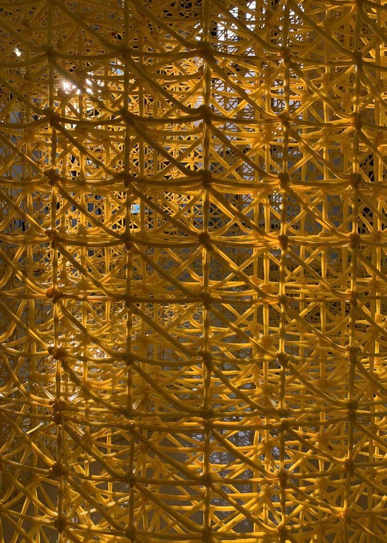
Carbon Fiber
Academic Work / Team Work 2020.10-2020.11,5 weeks
Collabrator: Ma Yifan
Instructor: Kuan-Ting Lai; Zee Leong
Personal Contribution: concept, model, drawing, fabrication
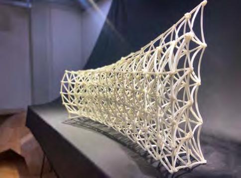
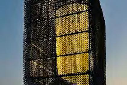
Compared with the independence of traditional landscape structures, this project is based on the study of form, trying to design a system that can be freely spliced and full of variations. In this system, through the splicing of the original form, an orderly and varied form and space can be formed to meet different needs and bring people rich experience. Even in a larger square scale, the combination of various forms can form a larger density and scale of landscape architecture.
We will use carbon fiber as the material to weave a prototype. Carbon fiber is light and strong, and its shaping is a process from soft to hard, with the potential to weave a smoother curve. The use of carbon fiber as a material can avoid the heaviness brought by traditional materials, making the volume more visually light. At the same time, we will also explore the possibility of using the robotic arm for production on a larger scale.`
Note: This project, named Open Project 152, is finished at Studio Alpha in Shanghai, China.
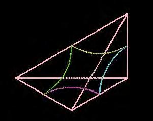
Concept
Like molecules, seemingly disordered arrangements actually follow a certain pattern. In this project, we use grids to control and manufacture complex associations based on simple shapes.Cut a rectangular pyramid from a cube and find an edge on each surface to form a space surface. In this way, we can control the splicing of the surface by controlling the splicing of the prism so as to produce more changes in the frame.
Generating Procedure
Form-Finding
The midpoint of the edge of the pyramid is used as the control point, and symmetric curves are selected, so that the surfaces can still be connected when interlocked or rotating.
Select the round arc and splice it to form a more compliant curve.
The curves are kept as low as possible to create more interior space.
Fabrication Logic
We analyzed the above stress state and used Kangaroo for stress analysis to get the stress line. Then we strengthen the area of stress concentration and get a generally applicable braiding method.
Fabrication Process
Surface Filling
Structure Strengthening
Surface Creation
Process Of Fabrication
During the project, the lamps is handmade, whereas it can be woven by a robotic arm, controlled by coding, if the protect is put into mass production. The process of handmaking can be roughly categorized into six steps, from assembling the mold to demolding the finished product.
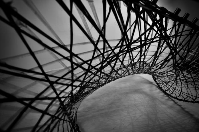
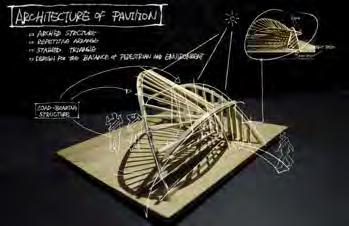
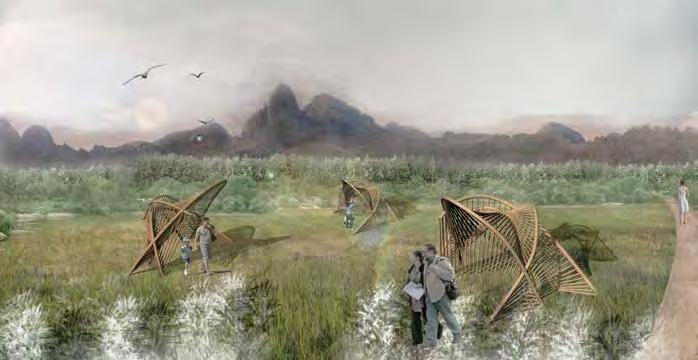
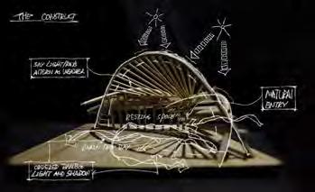
Crescent Moon near Bamboo Bamboo Construction Design Team Work 05/2019
The aim of this design is to create a resting pavilion for people to stop in the outdoors. We tried to construct a tensioned structure using the characteristics of bamboo material to form a clear structural system.
Generation Process
07
Other Works
Crescent Moon near Bamboo
Bamboo Construction Design / 05/2019
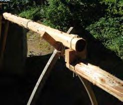
Water Harvester
Wood Construction Work / 07/2022
Infinity
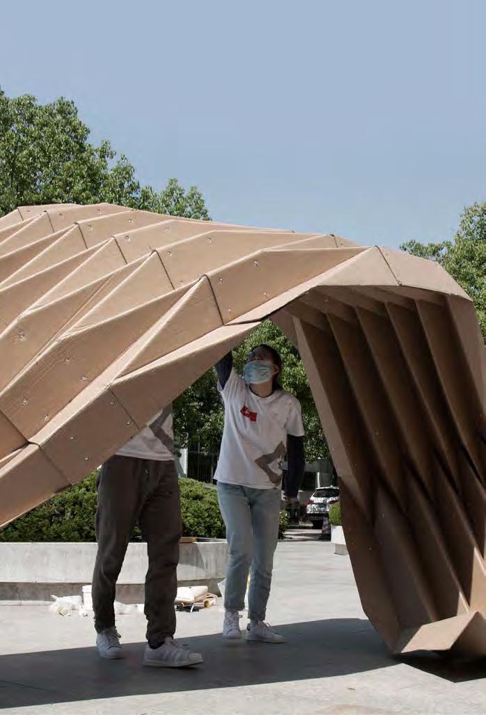
Cardboard Construction Design / 04/2018
Cliff City
Parametric Design / 02/2019
The idea was how to collect rainwater from the roof of the darkroom and conduct it to the people under the shelf. We chose to treat the inside of the pipe by burning the carbonised surface, so that the carbonised surface can naturally filter and absorb some magazines and harmful substances to produce clean water for human use, and we chose to hang a section of the support, so that the structure on the outside can finally be connected to the original construction.
Infinity
Cardboard Construction Design Team Work 04/2018
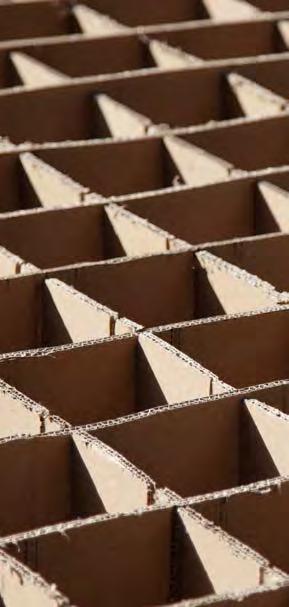
The purpose of this construction is to create a fun space for children to play in, Considering that the material is hard cardboard board, I adopted the method of origami to increase the structural strength of the cardboard, and to make the cardboard have the variability of linking and stretching. In form, I adopted the Mobius ring as the prototype, hoping to create more diverse spatial experience in a space of less than 10 square meters