18 minute read
Replacing components

from 2011_mini_cooper

On-board vehicle tool kit
Your vehicle comes with an onboard vehicle tool kit that varies with the equipment version; it is stored underneath the flat load floor. > Mobility System with onboard vehicle tool kit and tire change set* 142 > Tire change set with onboard vehicle tool kit for space-saver spare tire 144
Advertisement
Wiper blades
Changing the front wiper blades
1. Fold up the wiper arm.
2. Position the wiper blade horizontally. 3. Press the securing spring, arrow. 4. Unhook the wiper blade toward the windshield. 5. Pull the wiper blade past the wiper arm toward the top. 6. Insert the new wiper blade. 7. Press into position until you hear it engage. 8. Fold down the wiper arm. To avoid damage, make sure that the wiper arms are against the windshield before you open the hood.<

MINI: changing the rear wiper blade

1. Fold up the wiper arm. 2. Rotate the wiper blade toward the back as far as it will go, arrow. 3. Press the wiper blade against the limit and thus out of the mounting. 4. Press the new wiper blade into the fixture until it engages audibly.
Lamps and bulbs
Lamps and bulbs make an essential contribution to vehicle safety. They should, therefore, be handled carefully. The manufacturer of your MINI recommends having your MINI dealer perform any work that you do not feel competent to perform yourself or that is not described here. Never touch the glass of new bulbs with your bare fingers, as even minute amounts of contamination will burn into the bulb's surface and reduce its service life. Use a clean tissue, cloth or something similar, or hold the bulb by its base.< You can obtain a selection of replacement bulbs at your MINI dealer.
When working on electrical systems, always begin by switching off the consumer in question; otherwise, short circuits could result. To avoid possible injury or equipment damage when replacing bulbs, observe any instructions provided by the bulb manufacturer.< Caring for headlamps, refer to page 134. For any bulb replacement not described below, contact a MINI dealer or a workshop that has specially trained personnel working in accordance with the specifications of the MINI manufacturer.< For checking and adjusting headlamp aim, please contact your MINI dealer.<
Light-emitting diodes LEDs
Light-emitting diodes installed behind translucent lenses serve as the light sources for many of the controls and displays in your vehicle. These light-emitting diodes are related to conventional laser diodes, and legislation defines them as Class 1 light-emitting diodes. Do not remove the covers or expose the eyes directly to the unfiltered light source for several hours; otherwise, this could cause irritation of the retina.<
Headlight glass lens
In cool or humid weather, condensation may occur on the interior of outside lights. The condensation disappears a short time after the light is switched on. The headlamp glasses do not need to be changed. If a lot of moisture is present, e.g. water droplets in the light, have them checked by your service center.
Xenon lamps*
The service life of these bulbs is very long and the probability of failure very low, provided that they are not switched on and off an excessive number of times. If a xenon lamp fails nevertheless, switch on the fog lamps and continue the journey with great care, provided that local legislation does not prohibit this. Have any work on the xenon lamp system, including bulb replacement, carried out only by a MINI dealer or a workshop that has specially trained personnel working in accordance with the specifications of the MINI manufacturer. Due to high voltage, there is a risk of fatal injury if work on the xenon lamps is carried out improperly.<
Halogen low beams and high beams
H13 bulb, 60/55 watts The H13 bulb is pressurized. Therefore, wear safety glasses and protective gloves. Otherwise, there is a risk of injury if the bulb is damaged.< Be careful when installing the cover; otherwise, leaks could occur and cause damage to the headlamp system.<
Accessing the lamp from the engine compartment
The low-beam/high-beam bulb can be changed from the engine compartment.
Removing the cover: 1. Press the tab. 2. Flip open the cover and take it out of the holder. Follow the same steps in reverse order to reattach the cover. Be careful when installing the cover; otherwise, leaks could occur and cause damage to the headlamp system.<

1. Turn the lamp counterclockwise, arrow 1, and remove it, arrow 2.
2. Push on the catch, arrow 1, and disconnect the connector, arrow 2.
3. To insert the new bulb and replace the cover, proceed in reverse order.
Turn signals, parking lamps, roadside parking lamps, and fog lamps
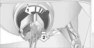
Accessing the lamps via the wheel well
1 Turn signal 2 Parking/roadside parking/fog lamps
Replacing a turn signal bulb
21 watt bulb, PY21W 1. Turn in the wheel. 2. Remove cover 1.
To do so, turn the cover counterclockwise. 3. Remove the inside cover.
To do so, turn the cover counterclockwise.
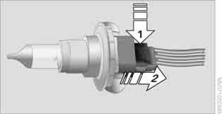
4. Unscrew the bulb counterclockwise.
5. To insert the new bulb and replace the covers, proceed in reverse order.


Replacing a parking/roadside parking lamp bulb
5watt bulb, W5W 1. Turn in the wheel. 2. Remove cover 2.
To do so, turn the cover counterclockwise. 3. Unscrew the upper bulb counterclockwise.
4. To insert the new bulb and replace the cover, proceed in reverse order.

H8 bulb, 35 watts 1. Turn in the wheel. 2. Remove cover 2.
To do so, turn the cover counterclockwise. 3. Pull the cable connector. 4. Unscrew the lower bulb counterclockwise.
5. To insert the new bulb and replace the cover, proceed in reverse order.

Side turn signals
5watt bulb, W5W 1. Push the lamp with the ventilation grate forward and remove.
2. Unscrew the bulb holder counterclockwise. 3. Pull out and replace the bulb. 4. To insert the new bulb and replace the cover, proceed in reverse order. 1 Turn signal
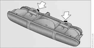
LED 2 Tail lamp bulb 21Watt/5Watt, W5W 3 Brake lamp bulb 21Watt/5Watt, W5W


Lamp access
MINI: Remove the cover from the sidewall of the cargo area.
MINI Convertible: Move the convertible top to its uppermost position, refer to Loading aid page 95, and remove the cover of the luggage compartment side wall.


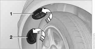
1. Unscrew the desired bulb counterclockwise, arrows 1.
Another bulb is located behind the luggage compartment side wall, arrow 2.
2. To insert the new bulb and replace the cover, proceed in reverse order.

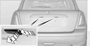
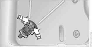
Rear fog lamps*/Reverse lights
Bulbs 16Watt, W16W Access the lamps via the rear or underside of the bumper.
1. Squeeze clamping clips, arrows, and remove bulb holder. 2. Unscrew bulb counterclockwise and replace. 3. To insert the new bulb and bulb holder, proceed in reverse order. 4. Re-engage the bulb holder so that it audibly clicks into place. 1. Using a screwdriver, push the lamp to the left in the tab of the lamp housing, arrow 1. 2. Remove the lamp, arrow 2. 3. Replace the bulb. 4. Insert the lamp.
Center brake lamp
This lamp uses LED technology for operation. In the event of a malfunction, contact your MINI dealer or a workshop that has specially trained personnel working in accordance with the specifications of your MINI manufacturer.
Repairing a flat tire
Safety measures in the event of a breakdown: Park the vehicle as far as possible from moving traffic and switch on the hazard warning flashers. Turn the steering wheel until the front wheels are in the straight-ahead position and engage the steering wheel lock. Engage the parking brake and shift into 1st or reverse gear or place the selector lever in position P. All passengers should be outside the vehicle and in a safe place, e.g. behind a guardrail. Erect a warning triangle or warning flasher at the appropriate distance if necessary. Comply with all safety guidelines and regulations.< In the event of a flat tire, different procedures should be followed depending on the equipment included in your vehicle:
> MINI Mobility System, refer to the following section > Run-flat tires, page 125 > Tire change with space-saver spare tire, page 144
Preparations
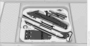
Use of the MINI Mobility System may be ineffective if the tire puncture measures approx. 1/8in/ 4mm or more. Contact the nearest MINI dealer if the tire cannot be made drivable with the Mobility System. Do not remove foreign bodies which have penetrated the tire if possible. Follow the instructions on using the Mobility System found on the compressor and the sealant bottle.< Remove the adhesive label for the speed limit from the sealant bottle and affix it to the steering wheel. The Mobility System with onboard vehicle tool kit and tire change set* is located under the floor mat in the cargo area.
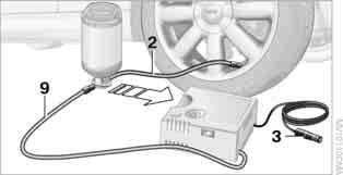
1 Sealant bottle 2 Hexagon wrench* 3 Extractor hook* 4 Vehicle jack* 5 Wheel stud wrench 6 Flat screwdriver/Phillips screwdriver, towing eyelet 7 Compressor 1 Sealant bottle and adhesive label with speed limit 2 Filling hose Note the use-by date on the sealant bottle.<


3 Holder for the sealant bottle 4 Compressor 5 Plug and cable for the socket in the vehicle interior, page 87 6 Connection hose to connect the compressor and sealant bottle or the compressor and wheel 7 On/off switch 8 Pressure gauge for indicating the tire inflation pressure 9 Release button for reducing the tire inflation pressure Connector, cable and connection hose are stored in the compressor housing.

To repair a tire puncture with the Mobility System, proceed as follows: > Filling the tire with sealant > Distribute the sealant > Correct the tire inflation pressure
Filling the tire with sealant
Proceed in the specified order; otherwise, sealant may emerge under high pressure.< 1. Shake the sealant bottle. 2. Pull the connecting hose 9 completely out of the compressor housing and screw it onto the connector of the sealant bottle. Make sure that the hose is not kinked. 3. Insert the sealant bottle on the compressor housing in an upright position.
4. Unscrew the dust cap from the valve of the defective wheel and screw the filling hose 2 of the sealant bottle onto the valve. 5. Ensure that the compressor is switched off. 6. Insert the plug 3 into the lighter socket/ power socket in the vehicle interior, page 87. 7. With the engine running:
Switch on the compressor and let is run for approx. 3 to 8minutes to fill the tire with sealant and achieve a tire inflation pressure of approx. 26psi/180kPa. When filling the tire with sealant, the inflation pressure can briefly rise to approx. 73psi/500kPa. Do not switch off the compressor during this phase.< Do not run the compressor for longer than 10minutes; otherwise, the device will overheat and possibly be damaged.< 8. Switch off the compressor. If an air pressure of 26psi/180kPa is not reached: 1. Unscrew the filling hose 2 from the wheel and drive the vehicle forward and backward approx. 33ft/10m to distribute the liquid sealant in the tire evenly. 2. Inflate the tire again with the compressor. If an inflation pressure of 26psi/180kPa still cannot be reached, the tire is too heavily damaged. Please contact the nearest MINI dealer.<
Stowing Mobility System
1. Unscrew filler hose 2 of the sealant bottle from the wheel. 2. Unscrew connecting hose of the compressor 9 from the sealant bottle. 3. Connect the filler hose 2 of the sealant bottle to the unoccupied connection on the sealant bottle.
This prevents the rest of the sealant from escaping from the bottle. 4. Wrap the empty sealant bottle in suitable material to avoid dirtying the cargo area. 5. Stow Mobility System back in the vehicle.
Distributing the sealant
Immediately drive approx. 3mls/5km to evenly distribute the sealant. Do not exceed speeds of 50mph/ 80km/h. If possible, do not drop below 10mph/ 20km/h.<
Correct the tire inflation pressure
1. After driving approx. 3mls/5km or ten minutes, stop at a suitable location. 2. Screw the connection hose 2 of the compressor directly onto the tire valve.
3. Insert the plug 3 into the power socket in the vehicle interior. 4. Correct inflation pressure to 26psi/180kPa.
With the engine running: > To increase the inflation pressure: switch on the compressor. To check the current inflation pressure, switch off the compressor. Do not run the compressor for longer than 10minutes; otherwise, the device will overheat and possibly be damaged.< > To decrease the inflation pressure: press the release button 5. If the tire cannot maintain the inflation pressure, drive the vehicle again, refer to Distributing the sealant. Then repeat steps 1to4. If an inflation pressure of 26psi/180kPa still cannot be reached, the tire is too heavily damaged. Contact the nearest MINI dealer.<
Driving on
Do not exceed the permitted maximum speed of 50mph/80km/h; doing so may result in an accident.< Replace the defective tire as soon as possible and have the new wheel/tire assembly balanced. Have the Mobility System refilled.
Changing wheels
Space-saver spare tire*
To change a space-saver spare tire, proceed as follows: > Remove the space-saver spare tire, page 144 > Prepare for tire change, page 145 > Jack up vehicle, page 146 > Mount space-saver spare tire, page 146 > Tighten lug bolts, page 146 > Drive with space-saver spare tire, page 145 On vehicles with a space-saver spare tire, the tire change set with onboard tools is stored under the floor mat in the cargo area. 1 Chock, folding 2 Extractor hook* 3 Wheel stud wrench 4 Vehicle jack 5 Special wrench for removing the spacesaver spare tire 6 Flat screwdriver/Phillips screwdriver 7 Towing eyelet 8 Lifting handle The onboard vehicle tool kit includes a pouch with a plastic bag in which you can place the damaged wheel.

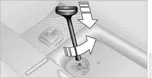
Removing the space-saver spare tire
The screw connection of the space-saver spare tire is under the floor mat in the cargo area, on the base of the storage compartment for the tire change set. 1. Unscrew the screw connection with the special wrench. 2. Take out the cover panel.

4. Raise the lifting handle slightly. 5. Squeeze the securing spring.
6. The space-saver spare tire is released and must be held by the lifting handle. 7. Lower the space-saver spare tire with the lifting handle. 8. Unscrew the lifting handle. 9. Pull the space-saver spare tire underneath the vehicle out toward the rear.
10. Position the space-saver spare tire with the valve facing upward. 11. Unscrew the valve extension from the valve of the space-saver spare tire. 12. Unscrew the dust cap from the extension and place it on the valve of the space-saver spare tire. Due to its different dimensions, the damaged wheel cannot be placed in the recess for the space-saver spare tire.<

Driving with the space-saver spare tire
Drive cautiously and do not exceed a speed of 50mph/80km/h. Changes may occur in vehicle handling such as lower track stability during braking, longer braking distances and changes in self-steering properties when close to the handling limit. These properties are more noticeable with winter tires.< Only one space-saver spare tire may be mounted at one time. Mount a wheel and tire of the original size as soon as possible, to avoid any safety risks.< Check the tire inflation pressure at the earliest opportunity and correct it if necessary. Replace the defective tire as soon as possible and have the new wheel/tire assembly balanced.<
Preparing for a tire change
Observe the safety precautions regarding flat tires on page 141.< Additional safety measures when changing tires: Only change the tire when parked on a surface that is level, firm and not slippery. The vehicle or the jack could slip sideways on soft or slippery support surfaces, such as snow, ice, flagstones, etc. Do not use a wooden block or similar object as a support base for the jack, as this would prevent it from extending to its full support height and reduce its load-carrying capacity. Do not lie under the vehicle or start the engine when the vehicle is supported by the jack; otherwise, there is a risk of fatal injury.<
1. Place the foldable chock* behind the front wheel on the other side of the vehicle or in front of the wheel if the vehicle is on an incline. If the wheel is changed on a surface with a more severe slope, take additional precautions to secure the vehicle from rolling. 2. Uncover the lug bolts if necessary. 3. Loosen the lug bolts by a half turn.
Jacking up the vehicle

The vehicle jack is designed for changing wheels only. Do not attempt to raise another vehicle model with it or to raise any load of any kind. To do so could cause accidents and personal injury.< 1. Place the jack at the jacking point closest to the wheel.
The jack base must be perpendicular to the surface beneath the jacking point.
2. During jacking up, insert the jack head in the square recess of the jacking point. 3. Jack the vehicle up until the wheel you are changing is raised off the ground. 1. Unscrew the lug bolts and remove the wheel. 2. Remove accumulations of mud or dirt from the mounting surfaces of the wheel and hub. Clean the lug bolts. 3. Lift the new wheel into place. 4. Screw at least two lug bolts finger-tight into opposite bolt holes. 5. Screw in the remaining bolts. 6. Tighten all the lug bolts firmly in a diagonal pattern. 7. Lower the vehicle. 8. Remove the jack.

Tightening the lug bolts
Tighten the lug bolts in a diagonal pattern. Immediately have the wheels checked with a calibrated torque wrench to ensure that the lug bolts are firmly seated. Otherwise, incorrectly tightened lug bolts can present a safety hazard.< Tightening torque: 103.3lbft or 140Nm. Replace the defective tire as soon as possible and have the new wheel/tire assembly balanced.
Vehicle battery
Maintenance
The battery is 100% maintenance-free, the electrolyte will last for the life of the battery when the vehicle is operated in a temperate climate.
Battery replacement
Only use vehicle batteries that have been approved for your vehicle by the manufacturer; otherwise, the vehicle could be damaged and systems or functions may not be fully available.< After a battery replacement, have the battery registered on the vehicle by your dealer to
Charging the battery
Only charge the battery in the vehicle when the engine is off. Connections, refer to Jump-starting on page 148.
Disposal
After replacing old batteries, return the used batteries to your MINI dealer or to a recycling center. Maintain the battery in an upright position for transport and storage. Always secure the battery against tipping over during transport.<
Power failure
After a temporary power loss, some equipment may not be fully functional and may require initialization. Individual settings are also lost and must be reprogrammed: > Time and date
These values must be updated, page 60. > Radio
Stations must be stored again, refer to the separate Owner's Manual for Radio. > Glass sunroof*, electric
It may only be possible to raise the sunroof, if applicable. The system must be initialized.
Contact your nearest MINI dealer.
Fuses
Do not attempt to repair a blown fuse or replace it with a fuse of a different color or Ampere rating. To do this could cause a fire in the vehicle resulting from a circuit overload. Have the fuse changed only by a MINI dealer or a workshop that has specially trained personnel working in accordance with the specifications of the MINI manufacturer.< A fuse allocation diagram is located on the inside of the fuse box cover panels.
Opening the cover
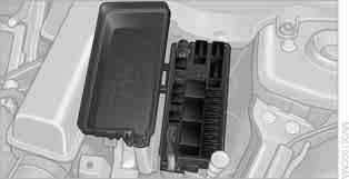
Press the latch.
In the vehicle interior

On the right side of the footwell.
Opening the cover
Press out at the recess.


