
- Connection INDEX 2 Steel Structure Axonometry 1 Description 01 02 04 10 11 16 21 22 25 30 39 48 54 3 Structural Drawings 4 Loads Analysis, Design & Check of secondary beam 5 Design & Check of other structure - Roof - Floor - Roof Truss - Cantilever - Border Secondary Beam - Floor Truss - Pillar
DESCRIPTION
The project consists in a mixed-use building made by circular ring with a height of 13.5 meters (2 stories, pilots in some parts for entrance). The upper level is for museum, it's an open space with some double height from the ground foor but without partitions due to the function light, and circulation reasons. The lower level is mainly for offce, commercial, cantin, and reception of the museum.
Because of the height, the pillars are used: STEEL CIRCULAR HOLLOW PILLAR (d=60mm, also considering architectural reason).
The roof secondary beams are IPE330, (they are dimensioned considering the heavist slab, for worker's mantainance of the building, with a live load of 0.5 KN/m2).
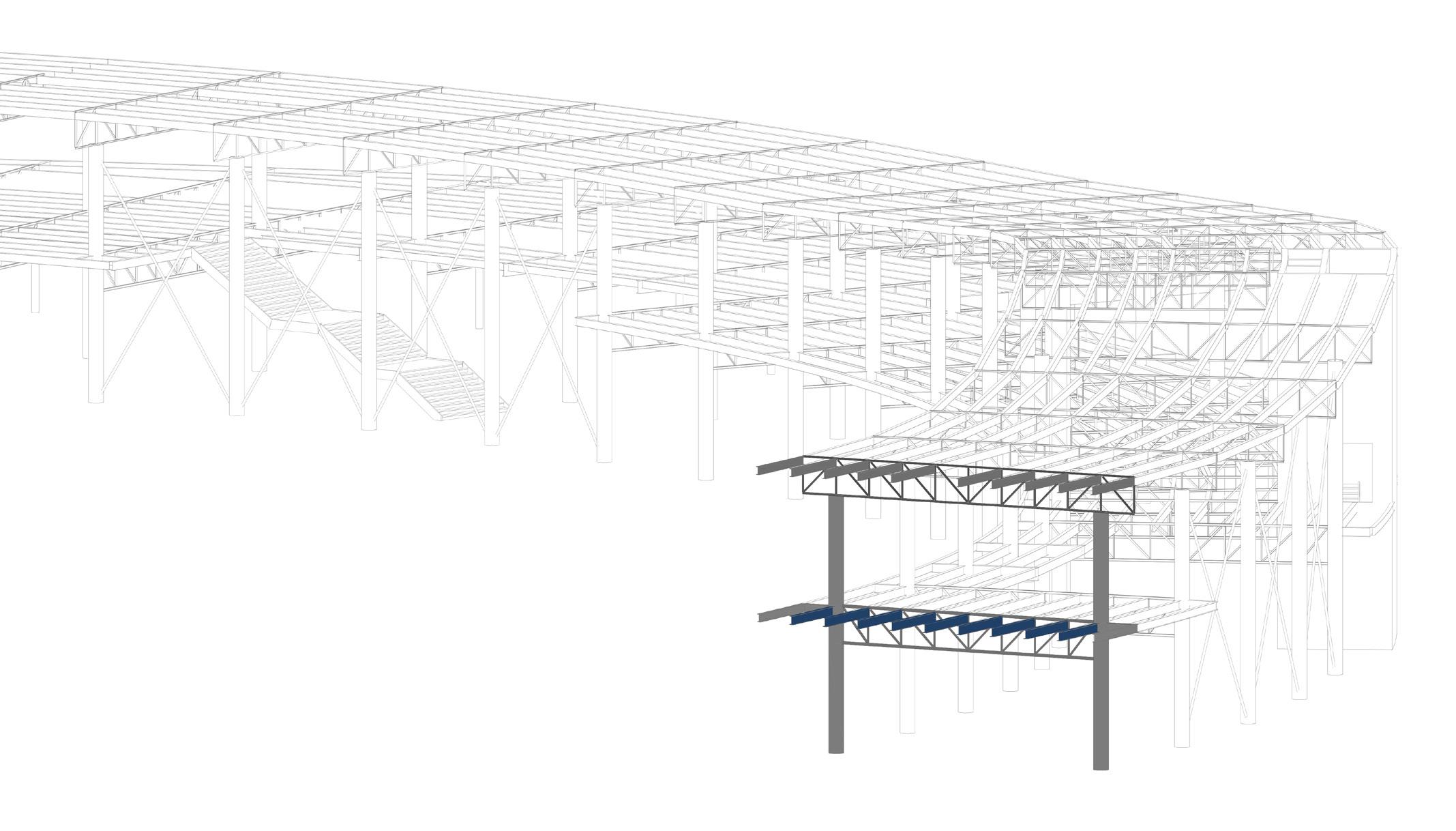
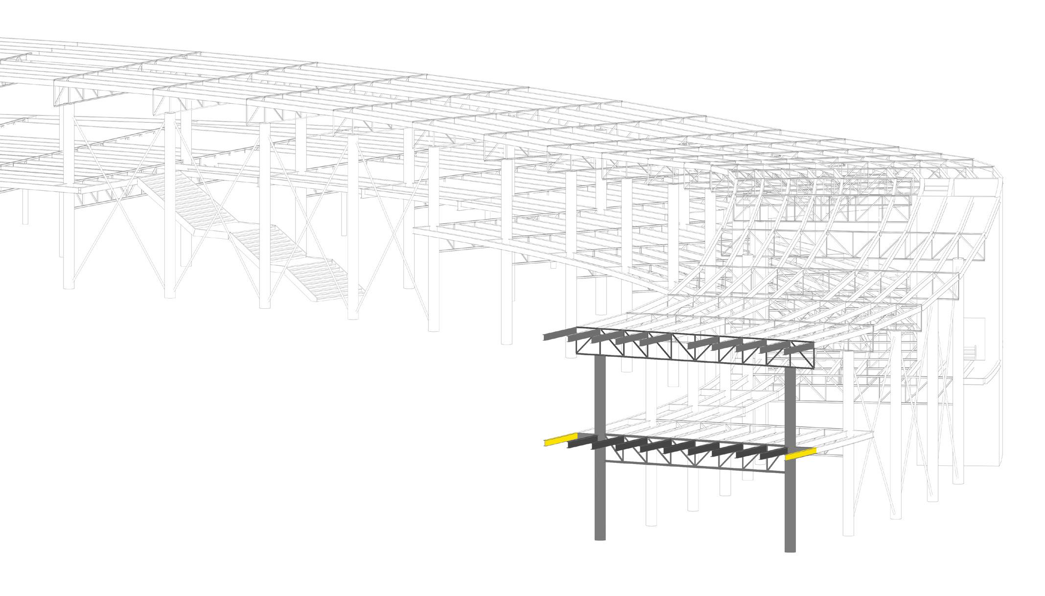
While the foor secondary beams are IPE 360. The border secondary beam IPE330 are adopted. The cantilever on the edges we use IPE360 where under concentrated loads.(they are dimensioned considering the heavist slab, the functon of muswum, with a live load of 5 KN/m2).
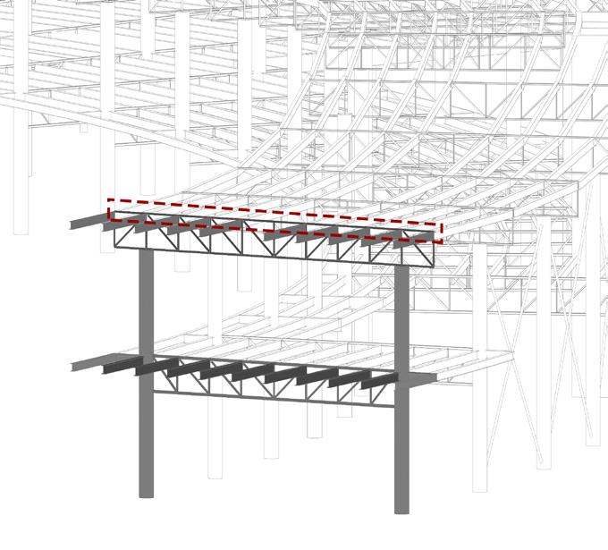
For roof truss, we use pairs of combination of UPN 65 (each profle) for all horizontal members, all vertical & diagonal members: pairs of L 50 (each profle).
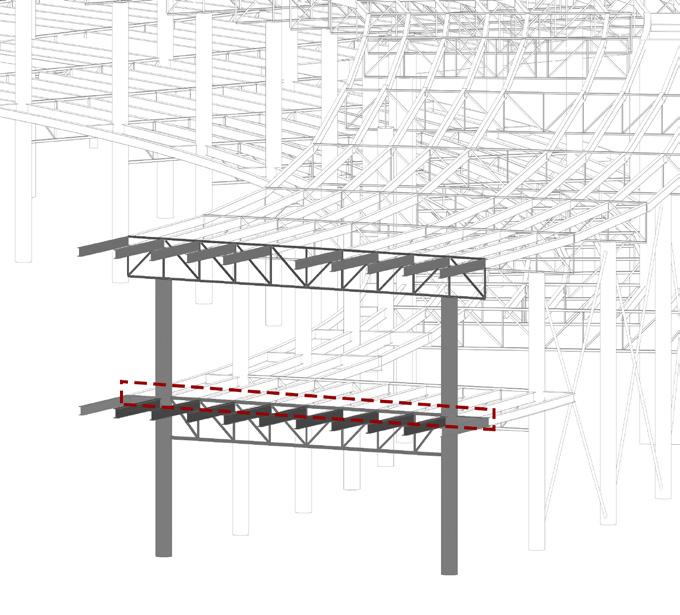
For foor truss, all horizontal members: pairs of combination of UPN 100 (each profle). For all diagonal members: pairs of combination of L 60 (each profle). For all vertical members: pairs of combination of L 50 (each profle).
The connection of cantilever and border secondary beams happends through a steel plate welded to the end of the section of the border secondary beams then bolted to the fange of the cantilevers. While the connection of truss elements are fllet welded with each other.
1
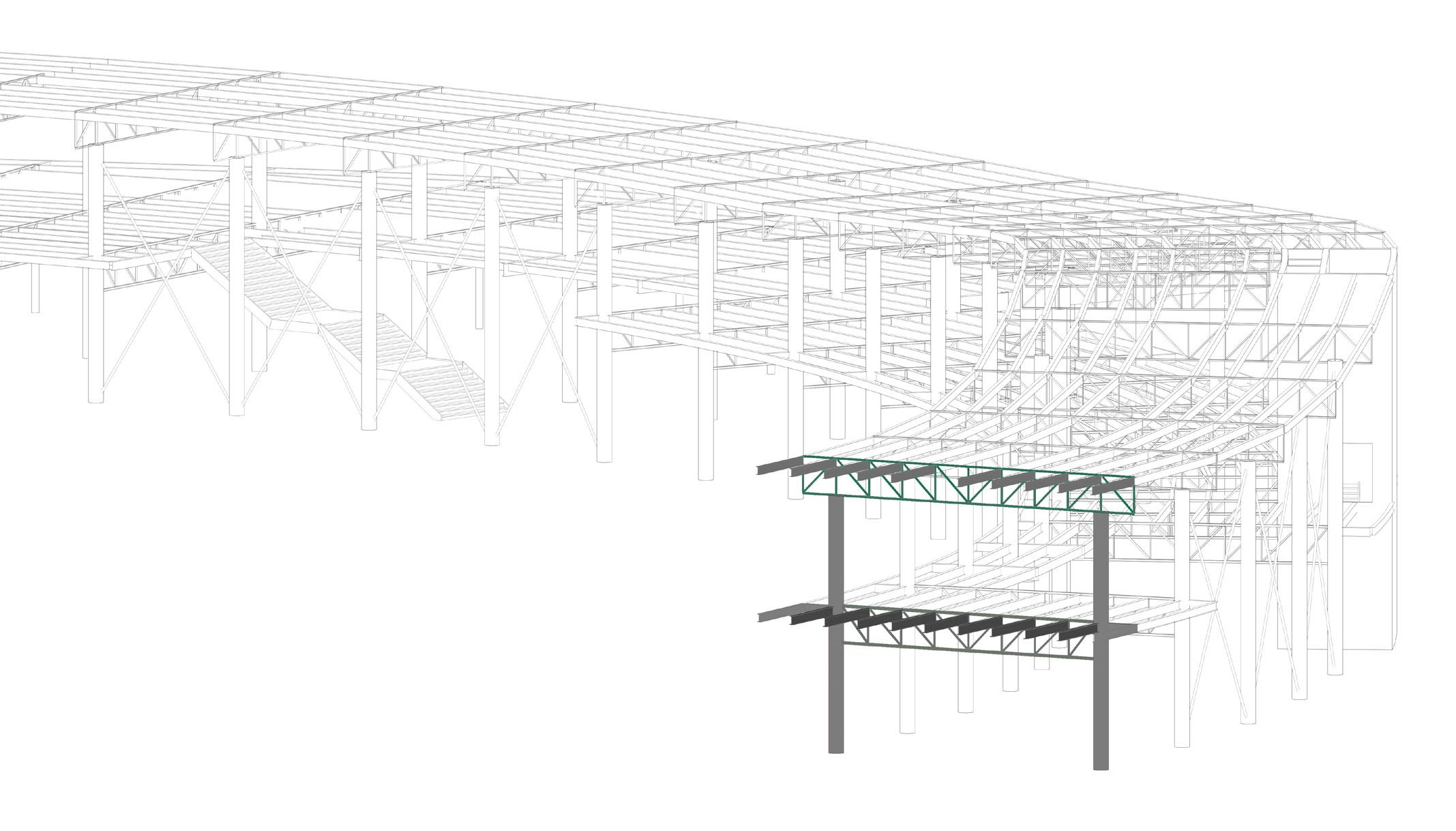
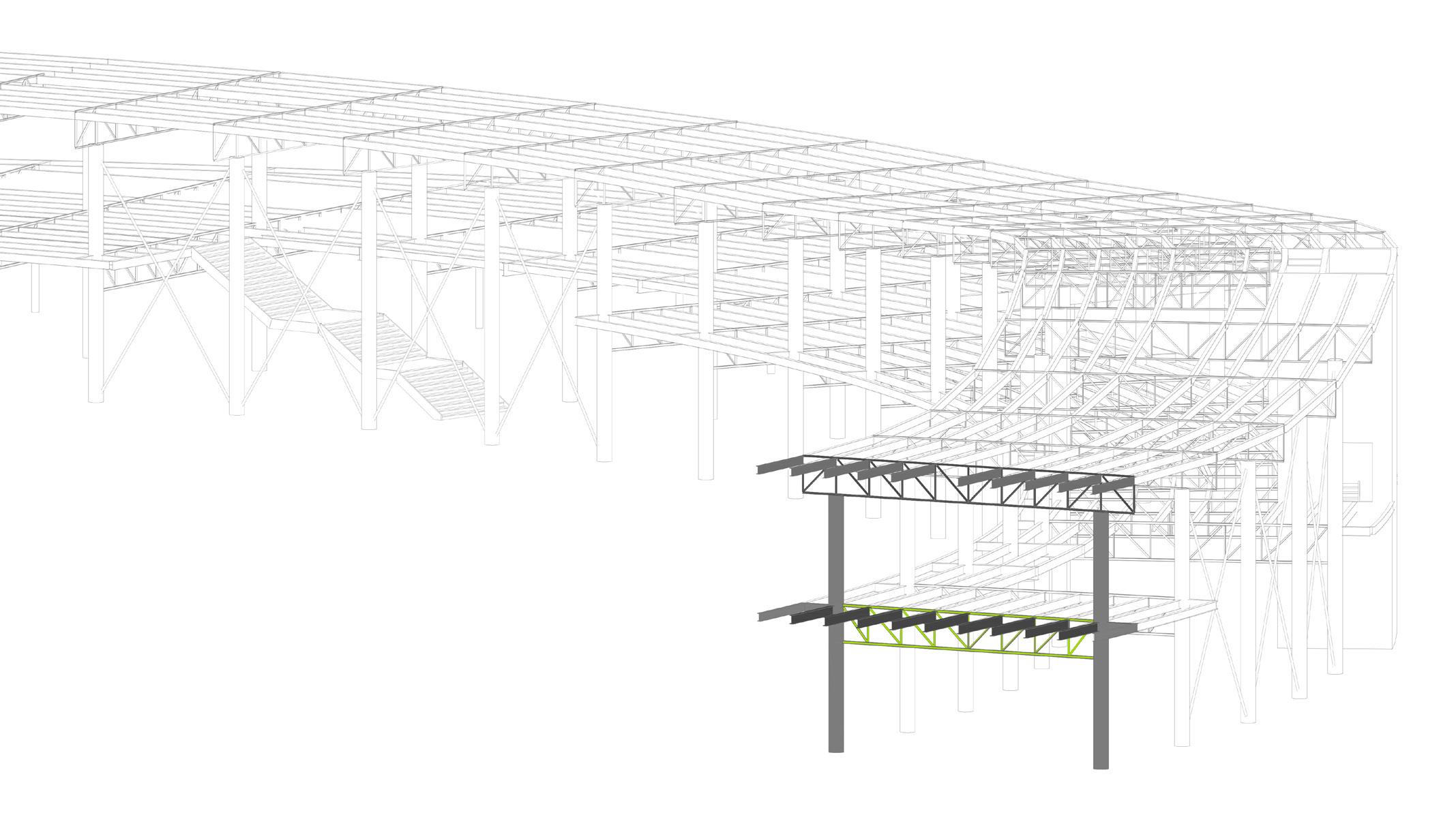
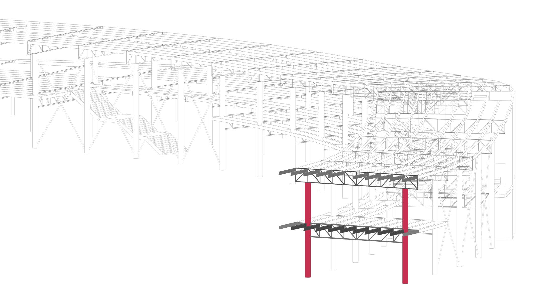
STEEL STRUCTURE AXONOMETRY
2
ROOF TRUSS - UPN 65/ L 50
FLOOR TRUSS - UPN 100/ L 60/ L 50
SECONDARY BEAM ON ROOF - IPE 330
SECONDARY BEAM ON FLOOR - IPE 360
SEONDARY BEAM ON BORDER - IPE 330
CANTILEVER - IPE 360
PILLAR - Hollow section d=610mm
3
STRUCTURAL DRAWINGS
4
FIRST FLOOR
GROUND FLOOR
5
6 SECTION
FIRST FLOOR 2
FIRST FLOOR 1
GROUND FLOOR 2
GROUND FLOOR 1
7
ROOF
SECTION OF EACH SEGMENT
8
PLAN OF EACH SEGMENT
CALCULATION PLAN
FIRST FLOOR
FIRST FLOOR
GROUND FLOOR
GROUND FLOOR
9
LOAD ANALYSIS, DESIGN & CHECK OF SECONDARY BEAM
10
Loads Computation
G2 Non Structural Permanent Loads
From the criteria for collaborating slabs:
G2 Non Structural Permanent Loads: 2.8 KN/m2
Q1 - Live loads
Live loads of roof (maintenance): 0.5 KN/m2
11
Material Thichness mm Density KN/m3 Alluminium 3 27 Bituminous 5 0.007 Sceed 6 18 Eps insulation 250 10 Vapor barrier 5 0.007 Collaborating slab 150 13 False celling gypsium panel 20 4.5 Total 389 / Glass 6 24 Air 15 0.0129 Glass 4 24 Air in between 600 0.0129 Glass 15 24 Air 16 0.0129 Onyx solar panel 10 24 Total 666 / Concrete resin flooring 70 24 Insulation support 100 8 Vapor barrier 5 0.007 Collaborating slab 15 13 Eps insulation 200 10 False celling gypsium panel 20 4.5 Total 230 / Concrete resin flooring 60 24 Total weight KN/m2 0.081 0.000035 0.108 2.5 0.000035 1.95 0.09 4.72907 0.144 0.0001935 0.096 0.00774 0.36 0.0002064 0.24 0.8481399 1.68 0.8 0.000035 0.195 2 0.09 4.765035 1.44 Weight of envolope Roof Internal double skin facade Mid floor pilotis Ground 239 2.77907 Material Thichness mm Density KN/m3 Alluminium 3 27 Bituminous 5 0.007 Sceed 6 18 Eps insulation 250 10 Vapor barrier 5 0.007 Collaborating slab 150 13 False celling gypsium panel 20 4.5 Total 389 / Glass 6 24 Air 15 0.0129 Glass 4 24 Air in between 600 0.0129 Glass 15 24 Air 16 0.0129 Onyx solar panel 10 24 Total 666 / Concrete resin flooring 70 24 Insulation support 100 8 Vapor barrier 5 0.007 Collaborating slab 15 13 Eps insulation 200 10 False celling gypsium panel 20 4.5 Total 230 / Concrete resin flooring 60 24 Insulation support 15 8 Eps insulation 200 10 Concrete deck 200 24 Air igloo membrane 650 0.0129 Reinforced concrete foundation slab 40 24 Sceed 80 18 Total 1245 Glass 6 24 Air 15 0.0129 Glass 4 24 Air in between 600 0.0129 Glass 15 24 Gas argon 16 0.017841 Onyx solar panel 10 24 Total 666 Total weight KN/m2 0.081 0.000035 0.108 2.5 0.000035 1.95 0.09 4.72907 0.144 0.0001935 0.096 0.00774 0.36 0.0002064 0.24 0.8481399 1.68 0.8 0.000035 0.195 2 0.09 4.765035 1.44 0.12 2 4.8 0.008385 0.96 1.44 10.768385 0.144 0.0001935 0.096 0.00774 0.36 0.000285456 0.24 0.848218956 Weight of envolope Roof Internal double skin facade Mid floor pilotis Ground External double skin facade 120
ROOF
Q2 - Snow loads
Mi is the shape factor
Qsk is the ground snow load
Ce is the snow exposure factor
Ct is the thermal factor
Qs=Mi*Qsk*Ce*Ct=0.8*1.5*1*1=1.2KN/m2
G1 - Structural loads (Collaborating slab)
G1 - Structural loads (Collaborating slab) = 0.15m * 13KN/m3 = 1.95 KN/m2
Ultimate limit state fundamental combination
G1 Structural Loads: 1.95 KN/m2 * 1.3 = 2.535 KN/m2
G2 Permanent Loads: 2.779 KN/m2 * 1.5 =4.168 KN/m2
G total: 2.535 + 4.168 = 6.7 KN/m2
Q1 Live loads: 0.5 * 1.5 = 0.75 KN/m2
Q2 Snow loads: 1.2 * 1.5 = 1.8 KN/m2
Q total: 0.75 + 1.8 = 2.55 KN/m2
G+Q at ULS: 6.7 + 2.55 = 9.25 KN/m2
SLS
G1=1.95 KN/m2
G2=2.779 KN/m2
G total=4.729 KN/m2
Q1=0.5 KN/m2
Q2=1.2 KN/m2
Q total=1.7 KN/m2
G total+Q at SLS=6.43 KN/m2
P=6.43*1.5 m=9.645 KN/m
(SLS)
Span of loading area of unit: 1.5 m
fd = 9.25 * 1.5 = 13.875 KN/m
13.875 KN/m (ULS)
12
Material Thichness mm Density KN/m3 Alluminium 3 27 Bituminous 5 0.007 Sceed 6 18 Eps insulation 250 10 Vapor barrier 5 0.007 Collaborating slab 150 13 False celling gypsium panel 20 4.5 Total 389 / Glass 6 24 Air 15 0.0129 Glass 4 24 Air in between 600 0.0129 Glass 15 24 Air 16 0.0129 Onyx solar panel 10 24 Total 666 / Concrete resin flooring 70 24 Insulation support 100 8 Vapor barrier 5 0.007 Collaborating slab 15 13 Eps insulation 200 10 False celling gypsium panel 20 4.5 Total 230 / Concrete resin flooring 60 24 Insulation support 15 8 Eps insulation 200 10 Concrete deck 200 24 Air igloo membrane 650 0.0129 Reinforced concrete foundation slab 40 24 Sceed 80 18 Total 1245 Glass 6 24 Air 15 0.0129 Glass 4 24 Air in between 600 0.0129 Glass 15 24 Gas argon 16 0.017841 Onyx solar panel 10 24 Total 666 Total weight KN/m2 0.081 0.000035 0.108 2.5 0.000035 1.95 0.09 4.72907 0.144 0.0001935 0.096 0.00774 0.36 0.0002064 0.24 0.8481399 1.68 0.8 0.000035 0.195 2 0.09 4.765035 1.44 0.12 2 4.8 0.008385 0.96 1.44 10.768385 0.144 0.0001935 0.096 0.00774 0.36 0.000285456 0.24 0.848218956 Weight of envolope Roof Internal double skin facade Mid floor pilotis Ground External double skin facade Material Thichness mm Density KN/m3 Alluminium 3 27 Bituminous 5 0.007 Sceed 6 18 Eps insulation 250 10 Vapor barrier 5 0.007 Collaborating slab 150 13 False celling gypsium panel 20 4.5 Total 389 / Glass 6 24 Air 15 0.0129 Glass 4 24 Air in between 600 0.0129 Glass 15 24 Air 16 0.0129 Onyx solar panel 10 24 Total 666 / Concrete resin flooring 70 24 Insulation support 100 8 Vapor barrier 5 0.007 Collaborating slab 15 13 Eps insulation 200 10 False celling gypsium panel 20 4.5 Total 230 / Concrete resin flooring 60 24 Insulation support 15 8 Eps insulation 200 10 Concrete deck 200 24 Air igloo membrane 650 0.0129 Reinforced concrete foundation slab 40 24 Sceed 80 18 Total 1245 Glass 6 24 Air 15 0.0129 Glass 4 24 Air in between 600 0.0129 Glass 15 24 Gas argon 16 0.017841 Onyx solar panel 10 24 Total 666 Total weight KN/m2 0.081 0.000035 0.108 2.5 0.000035 1.95 0.09 4.72907 0.144 0.0001935 0.096 0.00774 0.36 0.0002064 0.24 0.8481399 1.68 0.8 0.000035 0.195 2 0.09 4.765035 1.44 0.12 2 4.8 0.008385 0.96 1.44 10.768385 0.144 0.0001935 0.096 0.00774 0.36 0.000285456 0.24 0.848218956 Weight of envolope Roof Internal double skin facade Mid floor pilotis Ground External double skin facade
DESIGN OF SECONDARY BEAM ON ROOF

) efection
(SLS) P=9.645 KN/m
5*PL4/(384*EI)=L/250 (Italian code)
Imin=250*5*PL4/(LE*384)=(250*5*9.645*75003)/(210000*384)=1.00917*108 mm 4 =1.00917*104 cm 4 IPE 330
2)
(ULS) P=fd=13.875 KN/m2
Mmax=PL2/8 W=Fd S275
Wmin=M/fd=PL2/8*fd=(13.875*75002)/(8*275)=2.66069*109 mm 3
=266.069 cm 4 IPE 240
So we choose IPE 330
13
ROOF BEAM SECONDARY IPE 330
CHECK OF SECONDARY BEAM ON ROOF
teel profle IPE 330 S275
Height
Width
Thic ness fange
Thickness of Web
R radius
Area
Weight for unit length
Inertia moment
Resistance plastic modulus
q=(Q1+Q2)*Length of loading unit Area =(0.5+1.2)*1.5=2.55 KN/m
g=(G1+G2)*Length of loading unit Area =(1.95+2.779)*1.5=7.09 KN/m
Ala C/tf=[160-11.5-(2*18)]/ (2*11.5)=4.89 <= 10 class 1
Anima d/tw=[330-(2*11.5)-(2*18)]/7.5=36.1 <= 72 class 1
DISPLACEMENT CHECK
Maximun displacement is equal to :
max=5*(gt+g+q)L4/(384*EI)=5*(0.49+7.09+2.55)*75004/(384*210000*16270*104) =12.21 mm <=30 mm (L/250)
Displacement due to live load: 2=5*qL4/(384*EI)=5*2.55*75004/(384*210000*16270*104)=3.07 mm <=25 mm (L/300)
The chec is satisfed.
14
h b tf tw r A gt Iy Ix Wpl 330 160 11.5 7.5 18 62.6 0.49 788 16270 713 mm mm mm mm mm cm 2 N/mm cm 4 cm 4 cm 3
Acting shear and bending moment
VEd =(1.3gt+1.3g+1.5q)*L/2=(1.3*0.49+1.3*7.09+1.5*2.55)*7.5/2=51.29 KN
MEd =(1.3gt+1.3g+1.5q)*L2/8=(1.3*0.49+1.3*7.09+1.5*2.55)*7.52/8=96.18 KNm
Shear resistance
VpLRd=Arfy/(3-2*rM0)=[A-2b*tf+(tw+2r)*tf]*fy/(3-2*rM0)
=[6260-2*160*11.5+(7.5+2*18)*11.5]*275/(1.05*3-2)=465.767 KN
VEd <= VpLRd
Bending bearing capacity
McRd=WpL*fy/rM0=713*103*275/1.05=186.73 KNm
96.18 KNm (MEd) <= 186.73 KNm (McRd)
The chec is satisfed.
15
FLOOR
Loads Computation
G2 Non Structural Permanent Loads
From the criteria for collaborating slabs:
G2 Non Structural Permanent Loads:
Q1 - Live loads ive loads
(Cat. C3, museum)
16 Material Thichness mm Density KN/m3 Alluminium 3 27 Bituminous 5 0.007 Sceed 6 18 Eps insulation 250 10 Vapor barrier 5 0.007 Collaborating slab 150 13 False celling gypsium panel 20 4.5 Total 389 / Glass 6 24 Air 15 0.0129 Glass 4 24 Air in between 600 0.0129 Glass 15 24 Air 16 0.0129 Onyx solar panel 10 24 Total 666 / Concrete resin flooring 70 24 Insulation support 100 8 Vapor barrier 5 0.007 Collaborating slab 15 13 Eps insulation 200 10 False celling gypsium panel 20 4.5 Total 230 / Concrete resin flooring 60 24 Insulation support 15 8 Eps insulation 200 10 Concrete deck 200 24 Air igloo membrane 650 0.0129 Reinforced concrete foundation slab 40 24 Sceed 80 18 Total 1245 Glass 6 24 Air 15 0.0129 Glass 4 24 Air in between 600 0.0129 Glass 15 24 Gas argon 16 0.017841 Onyx solar panel 10 24 Total 666 Total weight KN/m2 0.081 0.000035 0.108 2.5 0.000035 1.95 0.09 4.72907 0.144 0.0001935 0.096 0.00774 0.36 0.0002064 0.24 0.8481399 1.68 0.8 0.000035 0.195 2 0.09 4.765035 1.44 0.12 2 4.8 0.008385 0.96 1.44 10.768385 0.144 0.0001935 0.096 0.00774 0.36 0.000285456 0.24 0.848218956 Weight of envolope Roof Internal double skin facade Mid floor pilotis Ground External double skin facade Material Thichness mm Density KN/m3 Alluminium 3 27 Bituminous 0.007 Sceed 6 18 Eps insulation 250 Vapor barrier 5 0.007 Collaborating slab 150 13 False celling gypsium panel 20 4.5 Total 389 / Glass 6 24 Air 15 0.0129 Glass 4 24 Air in between 600 0.0129 Glass 15 24 Air 0.0129 Onyx solar panel 24 Total 666 / Concrete resin flooring 70 24 Insulation support 100 8 Vapor barrier 5 0.007 Collaborating slab 15 13 Eps insulation 200 10 False celling gypsium panel 20 4.5 Total 230 / Concrete resin flooring 60 24 Insulation support 8 Eps insulation 200 10 Concrete deck Air igloo membrane 0.0129 Reinforced concrete foundation slab 40 24 Sceed Total 1245 Glass 6 24 Air 15 0.0129 Glass 4 24 Air in between 600 0.0129 Glass 15 24 Gas argon 16 0.017841 Onyx solar panel 24 Total 666 Total weight KN/m2 0.081 0.000035 0.108 2.5 0.000035 1.95 4.72907 0.144 0.0001935 0.096 0.00774 0.36 0.0002064 0.24 0.8481399 1.68 0.8 0.000035 0.195 2 0.09 4.765035 1.44 2 4.8 0.008385 0.96 10.768385 0.144 0.0001935 0.096 0.00774 0.36 0.000285456 0.24 0.848218956 Weight of envolope Roof Internal double skin facade Mid floor pilotis Ground External double skin facade Material Thichness mm Density KN/m3 Alluminium 3 27 Bituminous 5 0.007 Sceed 6 18 Eps insulation 250 10 Vapor barrier 5 0.007 Collaborating slab 150 13 False celling gypsium panel 20 4.5 Total 389 / Glass 6 24 Air 15 0.0129 Glass 4 24 Air in between 600 0.0129 Glass 15 24 Air 16 0.0129 Onyx solar panel 10 24 Total 666 / Concrete resin flooring 70 24 Insulation support 100 8 Vapor barrier 5 0.007 Collaborating slab 15 13 Eps insulation 200 10 False celling gypsium panel 20 4.5 Total 230 / Concrete resin flooring 60 24 Insulation support 15 8 Eps insulation 200 10 Concrete deck 200 24 Air igloo membrane 650 0.0129 Reinforced concrete foundation slab 40 24 Sceed 80 18 Total 1245 Glass 6 24 Air 15 0.0129 Glass 4 24 Air in between 600 0.0129 Glass 15 24 Gas argon 16 0.017841 Onyx solar panel 10 24 Total weight KN/m2 0.081 0.000035 0.108 2.5 0.000035 1.95 0.09 4.72907 0.144 0.0001935 0.096 0.00774 0.36 0.0002064 0.24 0.8481399 1.68 0.8 0.000035 0.195 2 0.09 4.765035 1.44 0.12 2 4.8 0.008385 0.96 1.44 10.768385 0.144 0.0001935 0.096 0.00774 0.36 0.000285456 0.24 Weight of envolope Roof Internal double skin facade Mid floor pilotis Ground External double skin facade Material Thichness mm Density KN/m3 Alluminium 3 27 Bituminous 0.007 Sceed 18 Eps insulation 250 10 Vapor barrier 5 0.007 Collaborating slab 150 13 False celling gypsium panel 20 4.5 Total 389 / Glass 6 24 Air 15 0.0129 Glass 4 24 Air in between 600 0.0129 Glass 15 24 Air 0.0129 Onyx solar panel 10 24 Total 666 / Concrete resin flooring 70 24 Insulation support 100 8 Vapor barrier 5 0.007 Collaborating slab 15 13 Eps insulation 200 False celling gypsium panel 20 4.5 Total 230 / Concrete resin flooring 60 24 Insulation support 15 8 Eps insulation 200 10 Concrete deck Air igloo membrane 650 0.0129 Reinforced concrete foundation slab 40 24 Sceed Total 1245 Glass 6 24 Air 15 0.0129 Glass 4 24 Air in between 600 0.0129 Glass 15 24 Gas argon 0.017841 Onyx solar panel 10 24 Total 666 Total weight KN/m2 0.081 0.000035 0.108 2.5 0.000035 1.95 0.09 4.72907 0.144 0.0001935 0.096 0.00774 0.36 0.0002064 0.24 0.8481399 1.68 0.8 0.000035 0.195 2 0.09 4.765035 1.44 0.12 2 4.8 0.008385 0.96 10.768385 0.144 0.0001935 0.096 0.00774 0.36 0.000285456 0.24 0.848218956 Weight of envolope Roof Internal double skin facade Mid floor pilotis Ground External double skin facade
KN/m2
of foor : 5
2.565 KN/m2
2.76 2.565 Material Thichness mm Density KN/m3 Alluminium 3 27 Bituminous 5 0.007 Sceed 6 18 Eps insulation 250 10 Vapor barrier 5 0.007 Collaborating slab 150 13 False celling gypsium panel 20 4.5 Total 389 / Glass 6 24 Air 15 0.0129 Glass 4 24 Air in between 600 0.0129 Glass 15 24 Air 16 0.0129 Onyx solar panel 10 24 Total 666 / Concrete resin flooring 70 24 Insulation support 100 8 Vapor barrier 5 0.007 Collaborating slab 15 13 Eps insulation 200 10 False celling gypsium panel 20 4.5 Total 230 / Concrete resin flooring 60 24 Insulation support 15 8 Eps insulation 200 10 Concrete deck 200 24 Air igloo membrane 650 0.0129 Reinforced concrete foundation slab 40 24 Sceed 80 18 Total 1245 Glass 6 24 Air 15 0.0129 Glass 4 24 Air in between 600 0.0129 Glass 15 24 Gas argon 16 0.017841 Onyx solar panel 10 24 Total 666 Total weight KN/m2 0.081 0.000035 0.108 2.5 0.000035 1.95 0.09 4.72907 0.144 0.0001935 0.096 0.00774 0.36 0.0002064 0.24 0.8481399 1.68 0.8 0.000035 0.195 2 0.09 4.765035 1.44 0.12 2 4.8 0.008385 0.96 1.44 10.768385 0.144 0.0001935 0.096 0.00774 0.36 0.000285456 0.24 0.848218956 Weight of envolope Roof Internal double skin facade Mid floor pilotis Ground External double skin facade Material Thichness mm Density KN/m3 Alluminium 3 27 Bituminous 5 0.007 Sceed 6 18 Eps insulation 250 10 Vapor barrier 5 0.007 Collaborating slab 150 13 False celling gypsium panel 20 4.5 Total 389 / Glass 6 24 Air 15 0.0129 Glass 4 24 Air in between 600 0.0129 Glass 15 24 Air 16 0.0129 Onyx solar panel 10 24 Total 666 / Concrete resin flooring 70 24 Insulation support 100 8 Vapor barrier 5 0.007 Collaborating slab 15 13 Eps insulation 200 10 False celling gypsium panel 20 4.5 Total weight KN/m2 0.081 0.000035 0.108 2.5 0.000035 1.95 0.09 4.72907 0.144 0.0001935 0.096 0.00774 0.36 0.0002064 0.24 0.8481399 1.68 0.8 0.000035 0.195 2 0.09 Weight of envolope Roof Internal double skin facade Mid floor pilotis 210 195 120
G1 Structural Permanent Loads
G1 Structural Permanent Loads: 0.195
Q1 - Live loads
Ultimate limit state fundamental combination
G1 Structural Loads: 0.195 KN/m2 * 1.3 = 0.25 KN/m2
G2 Permanent Loads: 2.565 KN/m2 * 1.5 =3.85KN/m2
G total: 0.25 + 3.85 = 4.1 KN/m2
Q1 Live loads: 5 * 1.5 = 7.5 KN/m2
G+Q at ULS: 4.1 + 7.5 = 11.6 KN/m2
Span of loading area of unit: 1.5 m
Fd = 11.6 * 1.5 = 17.4 KN/m
SLS
G1=0.195 KN/m2
G2=2.565 KN/m2
G=2.760 KN/m2
Q=5 KN/m2
G+Q=7.76 KN/m2
Interaxis:(G+Q)*1.5=11.64 KN/m
17
ive loads of foor :
KN/m2
5
KN/m2 Glass 4 24 Air in between 600 0.0129 Glass 15 24 Air 16 0.0129 Onyx solar panel 10 24 Total 666 / Concrete resin flooring 70 24 Insulation support 100 8 Vapor barrier 5 0.007 Collaborating slab 15 13 Eps insulation 200 10 False celling gypsium panel 20 4.5 Total 230 / Concrete resin flooring 60 24 Insulation support 15 8 Eps insulation 200 10 Concrete deck 200 24 Air igloo membrane 650 0.0129 Reinforced concrete foundation slab 40 24 Sceed 80 18 Total 1245 Glass 6 24 Air 15 0.0129 Glass 4 24 Air in between 600 0.0129 Glass 15 24 Gas argon 16 0.017841 Onyx solar panel 10 24 Total 666 0.096 0.00774 0.36 0.0002064 0.24 0.8481399 1.68 0.8 0.000035 0.195 2 0.09 4.765035 1.44 0.12 2 4.8 0.008385 0.96 1.44 10.768385 0.144 0.0001935 0.096 0.00774 0.36 0.000285456 0.24 0.848218956 Mid floor pilotis Ground External double skin facade Material Thichness mm Density KN/m3 Alluminium 3 27 Bituminous 5 0.007 Sceed 6 18 Eps insulation 250 10 Vapor barrier 5 0.007 Collaborating slab 150 13 False celling gypsium panel 20 4.5 Total 389 / Glass 6 24 Air 15 0.0129 Glass 4 24 Air in between 600 0.0129 Glass 15 24 Air 16 0.0129 Onyx solar panel 10 24 Total 666 / Concrete resin flooring 70 24 Insulation support 100 8 Vapor barrier 5 0.007 Collaborating slab 15 13 Eps insulation 200 10 False celling gypsium panel 20 4.5 Total 230 / Concrete resin flooring 60 24 Insulation support 15 8 Eps insulation 200 10 Concrete deck 200 24 Air igloo membrane 650 0.0129 Reinforced concrete foundation slab 40 24 Sceed 80 18 Total 1245 Glass 6 24 Air 15 0.0129 Glass 4 24 Air in between 600 0.0129 Glass 15 24 Gas argon 16 0.017841 Onyx solar panel 10 24 Total 666 Total weight KN/m2 0.081 0.000035 0.108 2.5 0.000035 1.95 0.09 4.72907 0.144 0.0001935 0.096 0.00774 0.36 0.0002064 0.24 0.8481399 1.68 0.8 0.000035 0.195 2 0.09 4.765035 1.44 0.12 2 4.8 0.008385 0.96 1.44 10.768385 0.144 0.0001935 0.096 0.00774 0.36 0.000285456 0.24 0.848218956 Weight of envolope Roof Internal double skin facade Mid floor pilotis Ground External double skin facade
17.4 KN/m
DESIGN OF THE SECONDARY BEAM OF FLOOR FLOOR BEAM SECONDARY
) efection
P=11.64 KN/m2 (at SLS)
P 4/(384*EI)=L/250 (Italian code)
Imin=250*5*PL4/(LE*384)=(250*5*11.64*75003)/(210000*384)=121791295 mm4 =12179.1295 cm 4 IPE 360
Mmax=PL2/8 W Fd S275
Wmin=PL2/8*fd=(17.4*75002)/(8*275)=444886.36 mm
18
So we choose IPE 360
2)
3=444.886 cm 4 IPE 270
IPE 360
CHECK OF SECONDARY BEAM ON FLOOR
teel profle IPE 360 S275
Height
Width
Thic ness fange
Thickness of Web
R radius
Area
Weight for unit length
Inertia moment
Resistance plastic modulus
q=(Q1+Q2)*Length of loading unit Area =5*1.5=7.5 KN/m
g=(G1+G2)*Length of loading unit Area =(0.195+2.565)*1.5=4.28 KN/m
Ala C/tf=[170-12.7-(2*8)]/(2*12.7)=5.562 <= 10 class 1
Anima d/tw=[360-(2*12.7)-(2*18)]/8=37.325 <= 72 class 1
DISPLACEMENT CHECK
Maximun displacement is equal to :
max=5*(gt+g+q)L4/(384*EI)=5*(0.57+4.28+7.5)*75004/(384*210000*16270*104) =15.8845 mm <=30 mm (L/250)
Displacement due to live load: 2=5*qL4/(384*EI)=5*7.5*75004/(384*210000*16270*104)=9.04 mm <=25 mm (L/300)
The chec is satisfed.
19
h b tf tw r A gt Iy Ix Wpl 360 170 12.7 8 18 72.7 0.57 1043 16270 1019 mm mm mm mm mm cm 2 N/mm cm 4 cm 4 cm 3
Acting shear and bending moment
VEd =(1.3gt+1.3g+1.5q)*L/2=(1.3*0.57+1.3*4.28+1.5*7.5)*7.5/2=65.8312 KN
MEd =(1.3gt+1.3g+1.5q)*L2/8=(1.3*0.57+1.3*4.28+1.5*7.5)*7.52/8=123.43 KNm
Shear resistance
VpLRd=Arfy/(3-2*rM0)=[A-2b*tf+(tw+2r)*tf]*fy/(3-2*rM0)
=[7270-2*170*12.7+(8+2*18)*12.7]*275/(1.05*3-2)=530.87 KN
VEd <= VpLRd 65.8312 <= 530.87
Bending bearing capacity
Rd/Wpe fyd=275/1.05=261 MPa
MRd=fyd*Wpe =261 MPa*1019*103 mm3=265.95*106 Nmm=265.95 KNm
Wpe=1019 cm3
MEd <= MRd 123.43 KNm <= 265.95 KNm
20
DESIGN & CHECK OF OTHER STRUCTURE
21
BORDER SECONDARY BEAM
Q1=5 KN/m2
G1=0.195 KN/m2
G2=2.565 KN/m2
ULS
G1=0.195*1.3=0.25 KN/m2
G2=2.565 KN/m2*1.5=3.85 KN/m2
Q1=5*1.5=7.5 KN/m2
GFV=GF F*1.5=418995 KN/m
(Facade load in ULS-interaxis)
interaxis: 1.5 m/2=0.75 m
Fd=(G1+Q1+G2)*0.75 m+GFu
=8.7 KN/m+8.7 KN/m=12.89 KN/m=P
SLS
G1=0.195 KN/m2
G2=2.565 KN/m2
G=2.760 KN/m2
Q=5 KN/m2
Fyd=(G+Q)*0.75 m=5.82 KN/m
12.89 KN/m
22
P BORDER SECONDARY BEAM IPE 330
DESIGN OF BORDER SECONDARY BEAM
) efection P fyd (SLS)=5.82 KN/m
P 4/(384*EI)=L/250
Imin=250*5*P*L4/(L*E*384)=250*5*5.82*75003/(210000*384)=60895647.3 mm4 =6089.5647 cm4
IPE 300
2) Bending moment P (ULS)=8.7 KN/m
Mmax=PL2 W Fd
Wmin=PL2/(8*fyd)=8.7*75002/(8*275)=329573.864 mm3=222.49 cm3
IPE 220
But we adopt IPE 330 for architecture reason.
CHECK OF FACADE SECONDARY BEAM
teel profle IPE 330
ness fange Thickness of Web
radius
Weight for unit length
moment Resistance plastic modulus
Ala C/tf=[160-11.5-(2*7.5)]/ (2*11.5)=5.804 <= 10 class 1
Anima d/tw=[330-(2*11.5)-(2*18)]/7.5=36.93 <= 72 class 1
KN/m
23
Height Width
R
Area
Inertia
q=5*0.75=3.75
g=(0.195+2.565)*0.25=2.07
gF=2.793
Thic
KN/m
KN/m
h b tf tw r A gt Ix Wpl 330 160 11.5 7.5 18 62.61 0.49 11766.89 713.15 mm mm mm mm mm cm 2 N/mm cm 4 cm 3
DISPLACEMENT CHECK
Maximun displacement is equal to : max=5*(gt+g+q)L4/(384*EI)=5*(0.491+2.07+3.75)*75004/ (384*210000*11766.89*104)
=15.1787 mm <=30 mm (L/250)
Displacement due to live load: 2=5*qL4/(384*EI)=5*3.75*75004/(384*210000*11766.89*104)=6.25 mm <=25 mm (L/300)
The chec is satisfed.
Acting shear and bending moment
Shear resistance
VpLRd=Arfy/(3-2 M0)=[A-2b*tf+(tw+2r)*tf]*fy/(3-2 M0) =[6261-2*160*11.5+(7.5+2*18)*11.5]*275/(1.05*3-2)=465.918 KN
Bending bearing capacity
24
VEd =(1.3gt+1.3g+1.5q)*L+1.5gF*L/2=[(1.3*0.4915+1.3*2.07+1.5*3.75)*7.5+ 1.5*2.793*7.5]/2=49.292 KN MEd =(1.3gt+1.3g+1.5q+1.5gF)*L2/8=92.42191 KNm
VEd <= VpLRd 49.292 <= 465.918 OK Rd/Wpe fyd=275/1.05=261 MPa MRd=fyd*Wpe =261 MPa*713.15*103 mm3=186.132*106 Nmm=186.132 KNm
<= MRd
MEd
OK
P2*R1=2*VED=49.292*2=98.384 KN
DESIGN OF CANTILEVER

T=P=98.384 KN
M=Mmax=P*L=98.389*1.5=147.576 KNm
max=P*L3 (3 EI) min=L/400=1500/400=3.75 mm
Imin=PL3 (3 E MIN)=98.384*103*15003/(3*210000*3.75)=140548.571 mm4
=14054.8571 cm4 IPE 360
25
CANTILEVER
CANTILEVER IPE 330
DISPLACEMENT CHECK
Maximun displacement is equal to :
max=PL3/(3EI)+5*gt*L4/(E*I)=98.38*103*15003/(3*210000*16265.62*104)+
5*0.52*15004/(384*2100001.265*104)=3.24+0.0011=3.2411<=3.75
Ved1*gt*1.3*L=0.5709*1.3*1.5=1.11325 KN
Med1=gt*1.3*L2/2=0.5709*1.3*1.52/2=0.83499 KNm
Ved2=P=98.384 KN
Med2=Mmax=147.576 KNm
Ved=Ved1+Ved2=99.49 KN Med=Med1+Med2=148.41 KNm
Shear resistance
VpLRd=Arfy/(3-2*rM0)=[A-2b*tf+(tw+2r)*tf]*fy/(3-2*rM0) =[7273-2*170*12.7+(18+2*18)*12.7]*127*151.211/(1.05*3-2)=530.87 KN
VEd <= VpLRd 99.49 KN <= 530.84 KN OK
Bending bearing capacity
=MRd/Wpe fyd=275/1.05=261 MPa
MEd <= MRd 148.41 KNm <= 265.95 KNm OK
26
MRd=fyd*Wpe =261 MPa*1019*103 mm3=265.95 KNm
Height Width
R
Area Weight
Inertia moment Resistance plastic modulus h b tf tw r A gt Ix Wpl 360 170 12.7 8 18 12.73 0.5709 16265.62 1019.15 mm mm mm mm mm cm 2 N/mm cm 4 cm 3
Thic ness fange Thickness of Web
radius
for unit length
Roof Truss
1、3: all horizontal members: P 6 (each profle)
2、4: all vertical & diagonal members: 0 (each profle)
Weight: 0.07 N/mm (single profle)
Weight: 0.058 N/mm (single profle)
27
Floor Truss
1、3: all horizontal members: P 00 (each profle)
2: all diagonal members: 60 (each profle)
4: all vertical members: 0 (each profle)
Weight: 0.01 N/mm (single profle)
Weight: 0.08 N/mm (single profle)
Weight: 0.064 N/mm (single profle)
28
FACADE
Weight of facade unit
1、 Internal skin
7.5/1.737=4.31
.3 facade unit per foor unit
Density of Glass: 2500 Kg/m3=25KN/m3
AI=1.737*6= 10.422 m2 VI=AI*0.01 m=0.10432 m3 GI=VI*25 KN/m3=2.6055 KN
2
、External skin
AE=(1.65+0.25)*6= 11.4 m2
GF=4.31*(GI+GE)=41.9 KN
VE=AE*0.025 m=0.285 m3 GE=VE*25 KN/m3=7.125 KN
29
TRUSS OF ROOF
Load from facade: GF/2=20.95 KN
Load from roof layers:
Roof stratigraphy weight at ULS: 8.95 KN/m2 (calculated before)
F=8.95*1.5*7.5=100.7 KN
Total load:
GF/2+F/2=71.3 KN
F=100.7 KN
30
Worst for vertical compression
Worst case for horizontal member compression
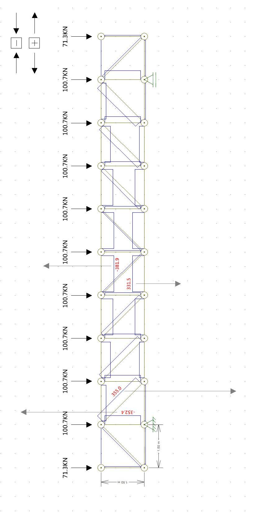
Worst case for horizontal member tension
Worst for diagonal tension
T NO! M NO!
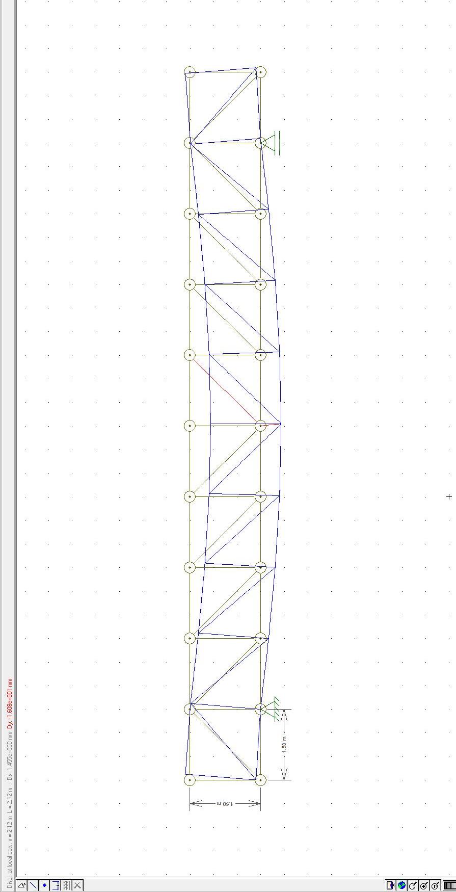
D Y =16 mm <= L/250=6*1500/250=36 mm
D Y =1.608*10 1 mm=16mm
HORIZONTAL MEMBER COMPRESSION (ROOF TRUSS) S275
Worst case for horizontal member compression from diagram
Nsd=A*fyk/rm Amin=Nsd*rm/fyk=381.9*1000*1.05/275=1458.1 mm2=14.58cm2
We choose o the minimum area of each steel profle: min/2=7.29cm2
from standard tabel, we choose P 6 steel profle 1)
Stability curve , 0.49
2)
Nsd=381.9 KN
L=1500 mm
Steel material S275
fyk=275 MPa
rm=1.05
fyd=fyk/rm=261.9 MPa
E=210000 MPa
33
4) 3) UPN 65 weight b h S (tw) t=R1 (tf) R2 (r) A d 0.07 42 65 5.5 7.5 4 9.03 34 N/mm mm mm mm mm mm cm 2 mm IX=57.5 cm4 IY=14.1 cm4 5) lassifcation of section 0. d/tw=(h-2tf-2r)/tw=(65-2*7.5-2*4)/5.5=0.76 <= 10 Class 1 c/tf =(42-7.5-2*4)/(2*5.5)=2.4 <= 10 Class 1 381.9KN 381.9KN
( fyk/Ncr)-2=[(903*2*275)/(25950*103)]-2=0.13
Ncr 2*E*Imin/L02=3.142*210000*1410*2*104/15002=25950 KN
0.
0. ( 0. ) 2]=0.5*[1+0.49*(0.13-0.2)+0.132]=0.53 ( 2 2)]=1/[0.53+(0.532-0.132)]=0.95 <= 1
Nbrd=X*A*fyd=0.95*903 mm2*2*261 MPa=447.8 KN
Nbrd=447.8 KN > Nsd=381.9 KN
The check is Ok!
34 6)
HORIZONTAL MEMBER TENSION (ROOF TRUSS) S275
Worst case for horizontal member tension from diagram
Axial force design NEd must respect: NEd/Nt*Rd <= 1
We choose 2 UPN 65 subjected to axial force Nsd=335 KN
h=65 mm b=42 mm tw=5.5 mm A=9.03cm2 d=34mm Fe 360
Where the calculated resistance to traction Nt,Rd of members should consider:
1) Gross section: NPL, Rd=A*fyk/rmo=2*903*275/1.05=473 KN
2) Section without hole:
Nu,Rd =0.9*Anet*fu/rm2=0.9*[2*(903-34*5.5)]*360/1.2=386.6 KN
NPL,Rd=473 KN > NEd=335 KN
Nu,Rd =386.6 KN > NEd=335 KN
Check OK!
So, top and bottom memeber of Roof Truss, we choose 2 UPN 65.
35
VERTICAL MEMBER COMPRESSION (ROOF TRUSS S275)
Worst case for vertical member compression from diagram
Nsd=A*fyk/rm
Amin=Nsd*rm/fyk=352.4*1000*1.05/275=13.45 cm2
We choose o the minimum area for each steel profle: min/2=6.7 cm2
from standard tabel, we choose L 50 (h=b=50 mm)
1)
Stability curve b, =0.34
2)
Nsd=352.4 KN
L=1500 mm
Steel material S275
fyk=275 MPa
rm=1.05
fyd=fyk/rm=261.9 MPa
E=210000 MPa
5) lassifcation of section 0.
d/tw=(h-2tf-2r)/tw=(50-2*8-2*7)/8=2.5 <= 10 Class 1
c/tf =(50-8-2*7)/(2*8)=1.75 <= 10 Class 1
IX=16.3 cm4 IY=16.3 cm4
36
4) 3
L
weight b h t (tw)(tf) r1 r2 (r) A d 0.058 50 50 8 3.5 7 7.41 1.5 N/mm mm mm mm mm mm mm cm 2
)
50
( fyk/Ncr)-2=[(741*2*275)/(29999.5*103)]-2=0.11
Ncr 2*E*Imin/L02=3.142*210000*1630*2*104/15002=29999.5 KN
0.3
0. ( 0. ) 2]=0.51
( 2 2)]=1/[0.51+(0.512-0.112)]=0.99 <= 1
Nbrd=X*A*fyd=0.99*741 mm2*2*261 MPa=382.9 KN
Nbrd=382.9 KN > Nsd=352.4 KN
The check is Ok!
37 6)
DIAGONAL MEMEBER TENSION (ROOF
TRUSS) S275
Worst case for horizontal member tension from diagram
L=1500*2-2
Axial force design NEd must respect: NEd/Nt*Rd <= 1
We choose 2 L 50 subjected to axial force Nsd=365 KN
h=50 mm b=50 mm t=8 mm A=7.41 cm2 d=1.5 mm Fe 360
Where the calculated resistance to traction Nt,Rd of members should consider:
1)、Gross section: NPL, Rd=A*fyk/rmo=2*741*275/1.05=388.14 KN
2)、Section without hole:
Nu,Rd =0.9*Anet*fu/rm2=0.9*[2*(741-1.5*8)]*360/1.2=437.4 KN
NPL,Rd=388.14 KN > NEd=365 KN
Nu,Rd =437.4 KN > NEd=365 KN
Check OK!
38
Truss of Floor
oad from foor layers (including live load):
Floor stratigraphy weight at ULS: 11.6 KN/m2 (calculated before)
F=11.6*1.5*7.5=130 KN
Total load
F=130 KN
39
Worst for vertical compression
Worst case for horizontal member compression
Worst case for horizontal member tension
Worst for diagonal tension
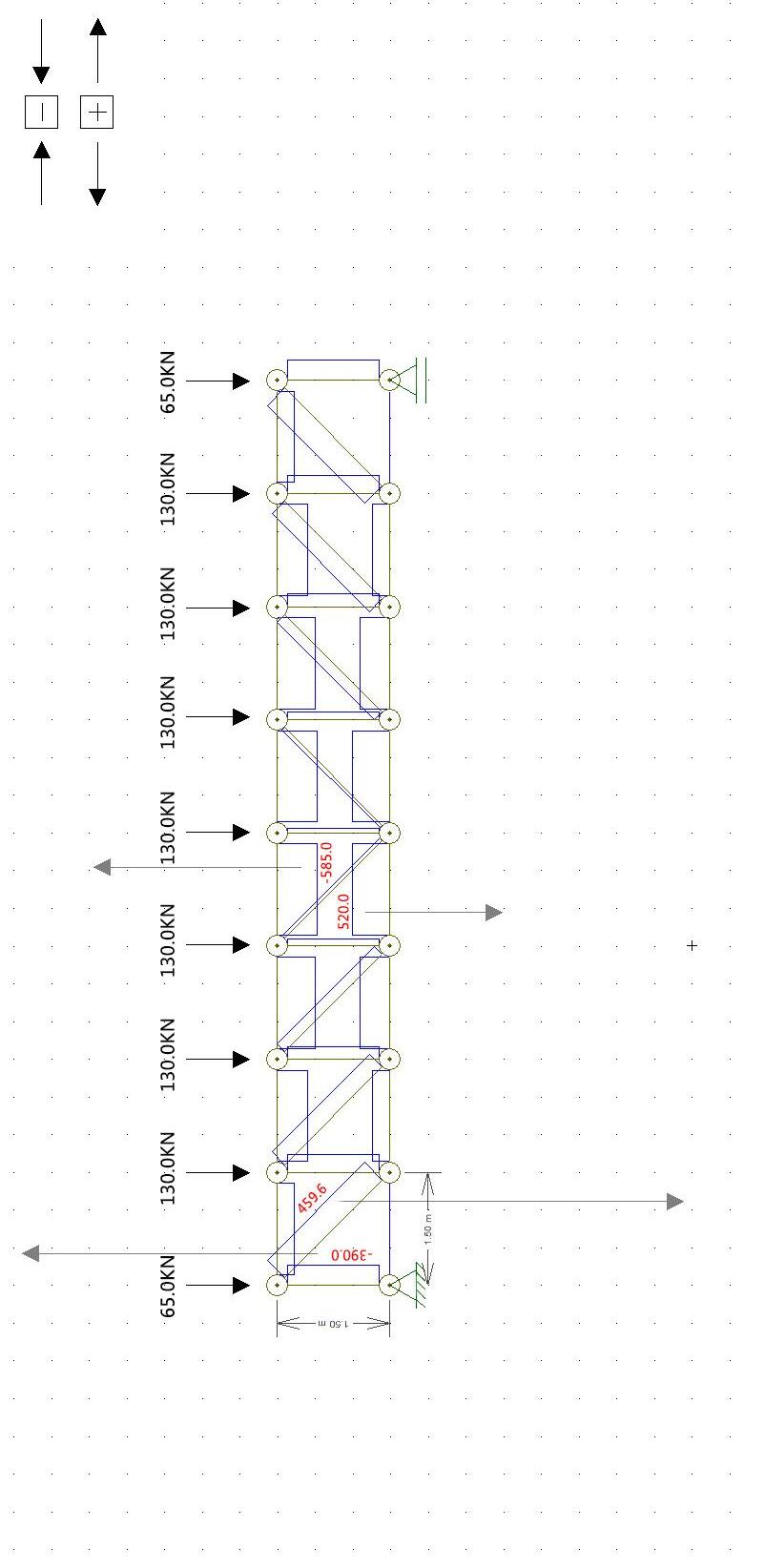
T NO! M NO!
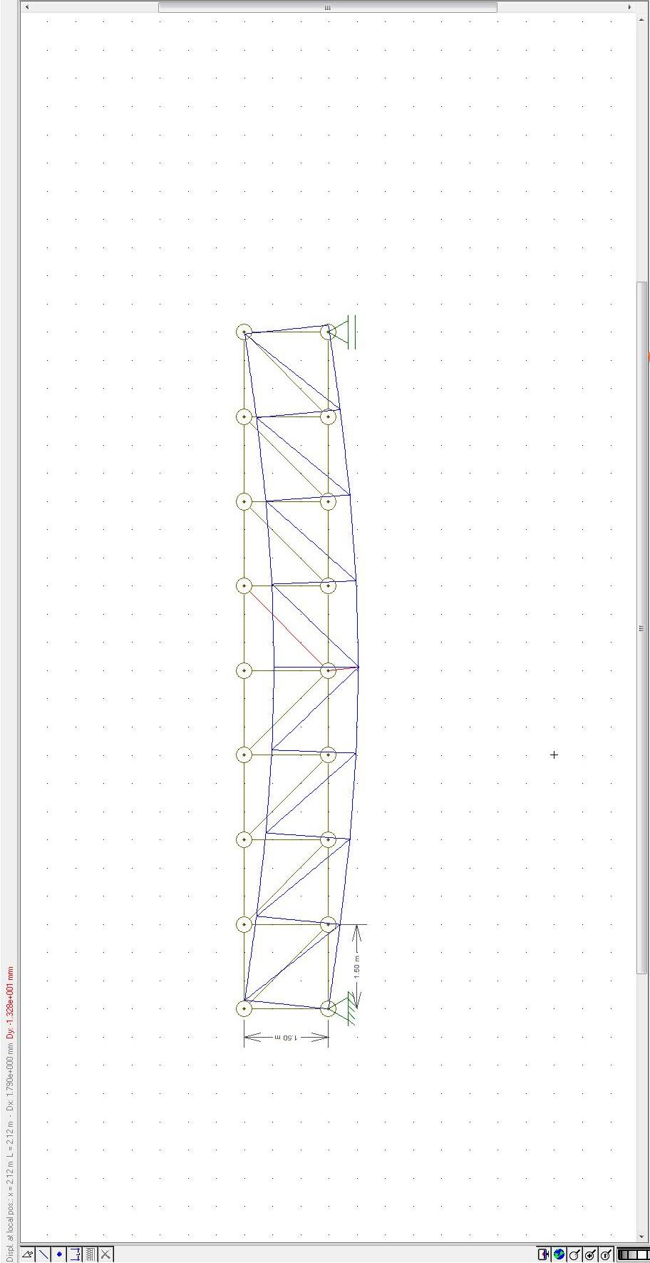
D Y =1.328*10 1 mm=13.2 mm <= L/450=6*1500/450=20 mm
HORIZONTAL MEMEBER COMPRESSION (FLOOR TRUSS) S275
Worst case for horizontal member compression from diagram
Nsd=A*fyk/rm Amin=Nsd*rm/fyk=585*1000*1.05/275=2233.6 mm2=22.34cm2
We choose o the minimum area of each steel profle: min/2=11.17cm2
from standard tabel, we choose P 00 steel profle
1)
Stability curve C, a=0.49
2)
Nsd=585 KN
L=1500 mm
Steel material S275
fyk=275 MPa
rm=1.05
fyd=fyk/rm=261.9 MPa
E=210000 MPa
42
4) 3) UPN 100 weight b h S (tw) t=R1 (tf) R2 (r) A d 0.1 50 100 6 8.5 4.5 13.5 64 N/mm mm mm mm mm mm cm 2 mm IX=206 cm4 IY=29.3 cm4 5)
0.
lassifcation of section
d/tw=(h-2tf-sr)/tw=(100-2*8.5-2*4.5)/6=12.3
> 10 Class 2
c/tf
=(50-2*8.5-2*4.5)/(2*8.5)=2.5 <= 10 Class 1
( fyk/Ncr)-2=[(1350*2*275)/(53925.4*103)]-2=0.12
Ncr 2*E*Imin/L02=3.142*210000*2930*2*104/15002=53925.4 KN
0.
0. ( 0. ) 2]=0.51
( 2 2)]=0.99 <= 1
Nbrd=X*A*fyd=0.99*1350 mm2*2*261 MPa=697.6 KN
Nbrd=697.6 KN > Nsd=585 KN
The check is Ok!
43 6)
HORIZONTAL MEMBER TENSIOND
(FLOOR TRUSS) S275
Worst case for horizontal member tension from diagram
Axial force design NEd must respect: NEd/Nt*Rd <= 1
We choose 2 UPN 100 subjected to axial force Nsd=520 KN
h=100 mm b=50 mm tw=6 mm A=13.5cm2 d=64mm Fe 360
Where the calculated resistance to traction Nt,Rd of members should consider:
1)、Gross section: NPL, Rd=A*fyk/rmo=2*1350*275/1.05=707 KN
2)、Section without hole:
Nu,Rd =0.9*Anet*fu/rm2=0.9*[2*(1350-64*6)]*360/1.2=521.6 KN
NPL,Rd=707 KN > NEd=520 KN
Nu,Rd =521.6 KN > NEd=520 KN
Check OK!
So, top and bottom memeber of Roof Truss, we choose 2 UPN 100.
44
VERTICAL MEMBER COMPRESSION (FLOOR TRUSS) S275
Worst case for vertical member compression from diagram
Nsd=A*fyk/rm Amin=Nsd*rm/fyk=390*1000*1.05/275=14.89 cm2
We choose o the minimum area for each steel profle: min/2=7.4 cm2
from standard table, we choose L 50 (h=b=50 mm) 1) Stability curve b, =0.34
2)
Nsd=390 KN
L=1500 mm
Steel material S275
fyk=275 MPa
rm=1.05
fyd=fyk/rm=261.9 MPa E=210000 MPa
5)
lassifcation of section 0.
d/tw=(h-2tf-2r)/tw=(50-2*9-2*7)/9=2 <= 10 Class 1
c/tf =(50-9-2*7)/(2*9)=1.5 <= 10 Class 1
cm4 IY=17.9 cm4
45
4) 3
L 50 weight b h t (tw)(tf) r1 r2 (r) A d 0.064 50 50 9 3.5 7 8.24 1.5 N/mm mm mm mm mm mm mm cm 2
)
IX=17.9
( fyk/Ncr)-2=[(824*2*275)/(32944.2*103)]-2=0.12
Ncr 2*E*Imin/L02=3.142*210000*1790*2*104/15002=32944.2 KN
0.3
0. ( 0. ) 2]=0.51
( 2 2)]=1/[0.51+(0.512-0.122)]=0.99 <= 1
Nb,rd=X*A*fyd=0.99*824 mm2*2*261 MPa=425.8 KN
Nb,rd=425.8 KN > Nsd=390 KN
The check is Ok!
46 6)
DIAGONAL MEMBER TENSION (FLOOR TRUSS) S275
Worst case for horizontal member tension from diagram
L=1500*2-2
Axial force design NEd must respect: NEd/Nt*Rd <= 1
We choose 2 L 60 subjected to axial force Nsd=459.5 KN
Where the calculated resistance to traction Nt,Rd of members should consider:
1)、Gross section: NPL, Rd=A*fyk/rmo=2*1110*275/1.05=581.4 KN
2)、Section without hole:
Nu,Rd =0.9*Anet*fu/rm2=0.9*[2*(1110-1.9*10)]*360/1.2=589.1 KN
NPL,Rd=581.4 KN > NEd=459.5 KN
Nu,Rd =589.1 KN > NEd=459.5 KN
Check OK!
47
h=60 mm b=60 mm t=10 mm A=11.1 cm2 d=1.9 mm Fe 360
48
PILLAR
1)
Weight of horizontal members: 0.07 KN/m
Number of horizontal members: 10
Length of horizontal members: 1.5 m
Weight of vertical/ diagonal members: 0.058 KN/m
Number of vertical memebers: 5.5
Number of diagonal memeber: 5
Length of diagonal member: 1.5*2-2
Length of vertical memeber: 1.5 m
Weight of roof truss:
G1= [0.07 KN/m *10*1.5 m+0.058 KN/m *(5.5*1.5 m+5*1.5*2-2m )]*1.3=2.8 KN
2)
Weight of horizontal members: 0.1 KN/m
Number of horizontal members: 8
Length of horizontal members: 1.5 m
Weight of diagonal members: 0.064 KN/m
Number of diagonal memebers: 4
Length of diagonal member: 1.5*2-2
Weight of vertical member: 0.064 KN/m
Number of vertical member: 3.5
Length of vertical member: 1.5 m
Weight of roof truss:
G2= (0.1 KN/m *8*1.5 m+0.008 KN/m *4*1.5*2-2 m+0.064*3.5*1.5 m)*1.3=2.87 KN
49
Self weight of roof truss (ULS)
Self weight of roof truss (ULS)
3) Self weight of cantilever IPE 360 (ULS)
Weight: 0.57 KN/m
Length: 1.5 m
G3= 0.57 KN/m*1.5 m*1.3=1.1 KN
4) Self weight of secondary beam on border IPE 330 (ULS)
Weight: 0.49 KN/m
Length: 7.5 m
G4= 0.49 KN/m*7.5 m*1.3=4.77 KN
5) Self weight of secondary beam on roof IPE 330 (ULS)
Weight: 0.49 KN/m
Length: 7.5 m
Number: 4.5
G5= 0.49 KN/m*7.5 m*4.5*1.3=21.5 KN
6) elf weight of secondary beam on foor IPE 360 ( )
G6= 0.57 KN/m*7.5 m*4.5*1.3=25 KN
50
Upper part of pillar (S275)
Nsd1=(100.7 KN*9+71.3 KN*2)/2+G1+G5+G4=553.5 KN
Nsd=A*fyk/γm
Amin=Nsd*γm/fyk=553.5*1000*1.05/275=21.1 cm2
The axial force on upper part of pillar is smaller, so we forcus on the lower part of pillars, where axial force is bigger.
51
Lower part of pillar
Nsd2=Nsd1+130 KN*7+65 KN*2+G2+G3+G4+G6
=553.5 KN+130 KN*7+65 KN*2+2.87 KN+1.1 KN+4.77 KN+25 KN=1627 KN
Nsd=A*fyk/γm
Amin=Nsd*γm/fyk=1627*1000*1.05/275=62.12 cm2
from standard table, we choose steel circular hollow section d=610 mm
1) Stability cruve a, α=0.21
2) Nsd2=1627 KN L=4.5 m
Steel material S275
fyk=275 mPa
γm=1.05
fyd=fyk/γm=261.9 mPa
E=21000 m Pa
3) t=10 mm
d=610 mm
A=188.5 cm2
I-84846.55cm2
4) Lo=βL=0.7L=0.7*4.5 m=3.15 m
52
) ( fyk/Ncr)-2=[188.5*100*275/(27628.5*103)]-2=0.36
Ncr 2EImin/Lo2=3.142*210000*84846.5*104/45002=27628.5 KN
0.
0. ( 0. ) 2]=0.5[1+0.21*(0.36-0.2)+0.362]=0.58 ( 2 2)-2]=1/[0.58+(0.582-0.362)-2]=0.96 <=1
Nb,rd=X*A*fyd=0.96*188.5*102*261=4723 KN > Nsd=1627 KN
Check is ok
53
1) Welded connection between truss memebers Fe 360
Design: Throat thickness a=5 mm
Check is ok
mm
mm
54 CONNECTIONS
L1=90
L2=210
id=t=356*103/(2*5*300)=118.7 mPa <= fu (3 w mw)=125.6 mPa
R1=(B-d)Nsd/B=15.4*Nsd/50=0.3Nsd R2=d*Nsd/B=34.6*Nsd/50=0.7Nsd L1/L2=R1/R2=(B-d)/d=3/7
55
R1=(B-d)Nsd/B=18.64*Nsd/60=0.3Nsd R2=d*Nsd/B=41.36*Nsd/60=0.7Nsd L1/L2=R1/R2=(B-d)/d=3/7 Design: Throat thickness a=7 mm L1=90 mm L2=210 mm id=t=459.6*103/(2*5*300)=109.4 mPa <= fu (3 w mw)=125.6 mPa Check is ok
2) Welded connection between truss memebers Fe 360
3) olt connection between foor secondary beam and foor cantilever
56
Design of bolts
From previous computation (Roof Load)
VED=1.3gsw*L+1.3gL+1.5g+PFtot/2
=(1.3*0.49+1.3*4.23+1.5*7.5)*7.5+20.95=151.8 KN
Choose 6 bolts
V1=VED/6=151.8/6=25.3 KN
H1=(VED/3)*(P2/P1)=(151.8/3)*(150/100)=75.9 KN
FI=(H12+V12)-2=(75.92+25.32)-2=80 KN
Choose Class 8.8 (fyb=480 N/mm2, ftb=600 N/mm2)
Fv,rd=0.6*ftb*Ares m2
Ares,min=(F1 m2)/(0.6*ftb)=(80*1000*1.25)/(0.6*800)=208.3 mm2
Choose M20, which Ares=245 mm2 > 208.3 mm2
Design of connection
do=d+2=20+2=22 mm
For distances from the edge:
e1 > 1.2do=1.2*22=26.4 mm, choose e1=65 mm
e2 > 1.2do=1.2*22=26.4 mm, choose e2=50 mm
For interenal distances:
P1 > 2.2do=2.2*22=48.4 mm
P2 > 2.4do=2.4*22=52.8 mm
P1, P2 < min(14t; 200)
choose t as thic ness of fange of IPE 330, t . mm . 6 mm
48.4 < P1 < 161, choose P1=100 mm
52.8 < P2 < 161, choose P2=100 mm
57
Check to shear force
F1=80 KN
Fv,Rd=0.6*ftb*Ares m2=0.6*800*2.45/1.25=94 KN
F1 < Fv,Rd Check is ok
Check to the hole of thinner element in connection
Bolluni interni: d=20 mm t=11.5 mm ftk=360 N/mm2 min P1/(3*do-0.25); ftb/ft min 00 (3 0. ) 600 360 min . 6 .6
. P2/do . . min . 00 . . min .66 .
K=2.5
Fb,Rd1 ftk d t m2=2.5*1*360*20*11.5/1.25=165.6 KN
2F1=160 KN < Fb,Rd1=165.6 KN Check is ok
Bolluni di Bordo:
2F1=160 KN < Fb,Rd2=163.9 KN Check is ok
58
min
min e1/(3*do);ftb/ft min 6 (3 ) 600 360 min 0. .6 0. min . e2/do . . min . 0 . . min .66 .
Fb,Rd2 ftkdt m . 0. 360 0 . . 63.
K=2.5
