1 minute read
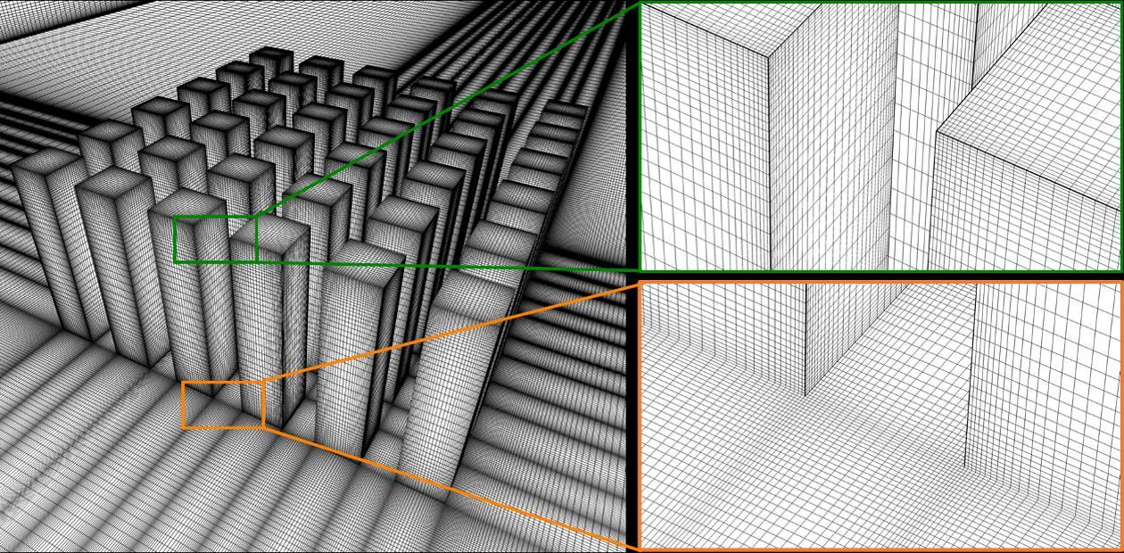
2.2.2 CFD validation: computational domain and grid
16 Chapter 2
dimensionless mean streamwise velocity (U/Uref) and turbulence intensity (TI/TIref) measured in the wind tunnel, where Uref (= 13.4 m/s) and TIref (= 8%) are the values at z = 0.14 m. Note that the incident flow profiles are defined as those measured in the empty tunnel at the position where the buildings would be located [83]. The building Reynolds number based on H and Uref is 123,724 while the Reynolds number based on the passage width between the buildings (w = 0.028 m) and Uref is 24,745. These values are well above the threshold of 11,000 for Reynolds number independent results [84]. The measurements are made for an approach-flow wind direction of 0°. The mean streamwise velocity (U) and turbulence intensity (TI) are sampled along six vertical lines in the vertical centerplane (y/B = 0) at x/B = -2.9, -1.94, -0.97, 0, 0.97 and 1.94 (Fig. 2.1c).
Advertisement
Figure 2.1. (a) Photograph of reduced-scale 2×2 array of high-rise buildings in wind-tunnel test section; (b) Incident vertical profiles of dimensionless mean streamwise velocity (U/Uref) and turbulence intensity (TI/TIref) measured in wind tunnel; (c) Locations of six vertical sampling lines in the centerplane (y/B = 0).
2.2.2 CFD validation: computational domain and grid
The CFD simulations are performed at wind tunnel scale. The computational domain is based on the WT test section and is shown in Fig. 2.2a. The downstream domain length is 15H, according to best practice guidelines for CFD simulations of wind flow in urban areas [85, 86]. The upstream


