
3 minute read
FENDER FOAM IONOMER, GILMAN CORPORATION
Benefits of intergral Ionomer Foam Fendering
• More Energy Absorption in smaller sizes
• Low-Hysteresis Reaction forces
• Low weight/high Buoyancy
• High – Density Skin
• Unsurpassed Functional Integrity
• Proven Effectiveness
• Impervious to Fuels and chemicals/ oil spills
• Non – toxic/Fire Safety
• Highly water repellent
Gilman Ionomer fenders are made from continuous extruded sheets with thick walled closed cell material. This material has the unique ability to link ionically between neighboring molecular chains with the same bond as the polymer itself. The surface is tough yet smooth and flexible: solid ionomer plastic is the primary material used for the covers of golf balls and bowling pins. These fenders offer superior strength, energy absorption and compression resistance and unsurpassed functional integrity in an almost infinite variety of shapes and sizes from buoys to ski barriers.
• Unaffected by Cold
• No Dissimilar materials
• Easy to repair
• High Visibility
• Non Marking/Nonabrasive
• Damage Control
• Fully Repairable
• Design Flexibility
FENDER FOAM IONOMER, BERTHING ENERGY AND REACTION FORCES
Assumptions:
• Finder size is expressed as diameter (in feet) by length overall (in feet)
• Rated berthing energy and reaction force are based on fender performance at 60% compression ratio
• Berthing energy and reaction force values for the 2 x 6 fender are based on testing performed in 1993. The berthing energy and reaction forces for the other fenders in this table were scaled from the nominal tested fender results using equations (11) and (12) from ASTM F2192-02
FAIRLEAD ROLLER - ANCHOR

FAIRLEAD ROLLER - TYPE A


FAIRLEAD ROLLER - JIS F2014
FAIRLEAD ROLLER - UNIVERSAL


CHOCK - BULWARK MOUNTING, JIS F2017-BC
CHOCK - BULWARK

MOUNTING, JIS

F2030-A
CHOCK - BULWARK MOUNTING, BOW, TYPE EU
CHOCK - MOUNTING, TYPE EU

SHEAVE - VERTICAL LEAD

SHEAVE - HORIZONTAL LEAD

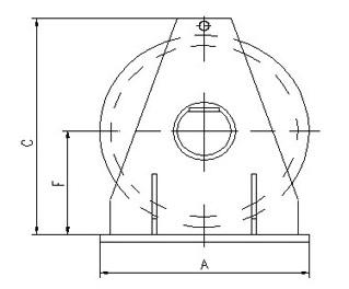
BRACKET - SMIT BRACKET

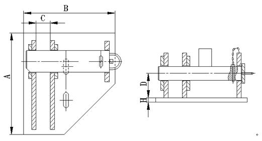
STOPPER - CHAIN CABLE STOPPER
BOLLARD - CURVED TYPE A

BOLLARD - DOCK TYPE J
BOLLARD - DOUBLE BITT LXY-B09
BOLLARD - DOUBLE BITT LXY-B10
BOLLARD - DOUBLE BIT DECK MOUNT LXY-B011


BOLLARD - DECK MOUNT LXY-B012


BOLLARD - SINGLE BITT
BOLLARD - SINGLE-BITE TYPE JIS

BOLLARD - TYPE STAG HORN
BOLLARD - T-HEAD


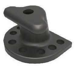
Anchors
The anchor is the key to effective anchoring or mooring. It is essential to know what to expect from various anchors. Resistance of an anchor to being dragged through a soil has been considered as occurring in two stages: first, biting into the bottom due to the ploughing effects of the flukes, and secondly, maintaining a continuous resistance to drag after it is planted into the bottom.
Holding power type anchors are directly proportional to projected fluke area, and shear strength of the bottom material, and inversely proportional to penetration-area resistance. In many cases a smaller anchor with favorable fluke area to weight ratio is more dependable than a heavier anchor.

Holding power for the two most widely used anchors are as follows:
• Stockless Type anchors in sand develop a holding power to weight ratio of seven to one. In mud it develops three to one. The angle of penetration in both cases is 45°.
• Lightweight Type (Danforth style) anchors in sand develop a holding power to weight ratio of twenty to one, with the angle of penetration being 30°. In mud it develops nine to one with the angle of penetration being 50°.
• The depth of penetration in all preceding cases is compiled from three to seven feet in sand, and from seventeen to twenty feet in mud. All calculations incorporate a 0° scope angle.
ANCHOR - DANFORTH STYLE / WORKBOAT
With the “hook" head forcing the flukes to dig in quickly, and the large fluke design providing tremendous holding power; this anchor offers terrific holding power in both sand and mud bottoms.


ANCHOR - STOCKLESS


ANCHOR - DELTA HHP


ANCHOR - AC-14


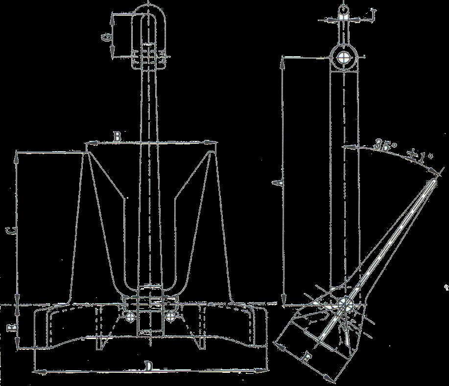
ANCHOR - ST OFFSHORE


ANCHOR - STS OFFSHORE


ANCHOR - DEAD WEIGHTS
Anchors
Anchors are available to 65 000 kg in weight. Measurements are holding capacity charts can be supplied. Selecting the correct anchor is dependent on the application. The water depth, soil conditions, holding power line ratios, distance to penetration/burial and installation methods all have to be considered when selecting the style and weight to be used.


Below are a list of the most common drag embedment type anchors used, they are usually used for temporary moorings or as an anchoring point for pulling systems.


