
10 minute read
SENSITIVE, CURRENT OPERATED, EARTH LEAKAGE PROTECTION-L. C. EALES


The petrol pump, then, is being diversified in many ways to satisfy the new and different functions required of it. In Sweden, where about a tenth of retail motor spirit business is done by credit card, experimental self-service pumps activated by personal credit cards, are in operation. At first sight the limitation of the use of this equipment to the small number of one's customers who hold such cards and who are prepared to serve themselves seems to be restrictive. However, only the actual results of these field trials will give the true position regarding their future use.
Also in the credit field is a key activated, self-service pump. Here a key, bearing a customer's personal code, activates a selected pump. Quantities taken are totalised on individual remote counters which correspond to the code on each key. This system could be of particular attraction to commercial fleet owners or to garages with high and costly credit sales.
Advertisement
The variations on this central theme of automation then seem limitless, and do provide technical solutions to commercial problems. Our market is getting bigger every day, but the number of filling stations is not increasing proportionately. Good labour is becoming more costly and difficult to find. In the right market conditions we must turn to these new retailing techniques for many of the answers.
It has been said that, " . . . the progress of automation must depend at first on the willingness of pioneer firms to act with imagination, and to spend considerable time in experimentation".
We are not lacking in imagination, but we must have the opportunity of assessing and evaluating the validity of new techniques. To do this, we must offer them to the motori.ng public in different areas and at one or se_veral of our ser".1ce stations. We look forward to the contmued co-operation of the Petroleum Acts Administration Officers, in allowing us to keep abreast of the rapidly expanding and changing retail petrol market of this country.
Contributed by L. C. EALES Technical Representative Findlay Durham and Brodie Sales Limited
The Reduction of Incendiary Sparking in Petrol Laden Atmospheres
Much attention has been given to the prevention of the ignition of explosive vapours by arcing in electrical equipment consequent on faults between current carrying parts of electrical systems but the dangers of incendiary sparking along earth paths has not been sufficiently appreciated. The Specifications and Codes of Practice applicable to petroleum vending specify Group II flameproof enclosures for electrical apparatus in accordance with British Standards Nos. 229 and 889 and compliance with the requirements of the Underwriters' Laboratories Incorporated of U.S.A. The instructions regarding earthing are, however confined to the all embracing sentence "The metai encl?sures to all apparatus and the conduit shall be efficiently earthed". Some local authorities specify that the resistance of the earth path shall not be greater than 1 ohm. The Institution of Electrical Engineers Regulations for the Electrical Equipment of Buildings stipulate that the impedance of the earth fault path shall be sufficiently low to enable an earth fault current of three times that. of the associated fuse rating or 1 i times the overload settmg of the circuit breaker to flow, i.e. for a 240v. to earth system protected by a 60 amp fuse the maximum resistance of the phase/earthloop must not exceed !. 3I 240 180 = 1 3 . hms
0 where E is the voltage to earth and I the fus~ rating. The impedance of the phase/loop includes a reactive con;i.ponent but resistance is the predominant factor and IS used in this article for simplicity.
Resistances of even less than 1.3 ohms are not low enough to prevent a momentarily rise in potential on the earthing system with the consequential danger of ?pen sparking to adjacent earthed metal and along fortu~tous parallel earth paths. With an earth return path havmg a
89
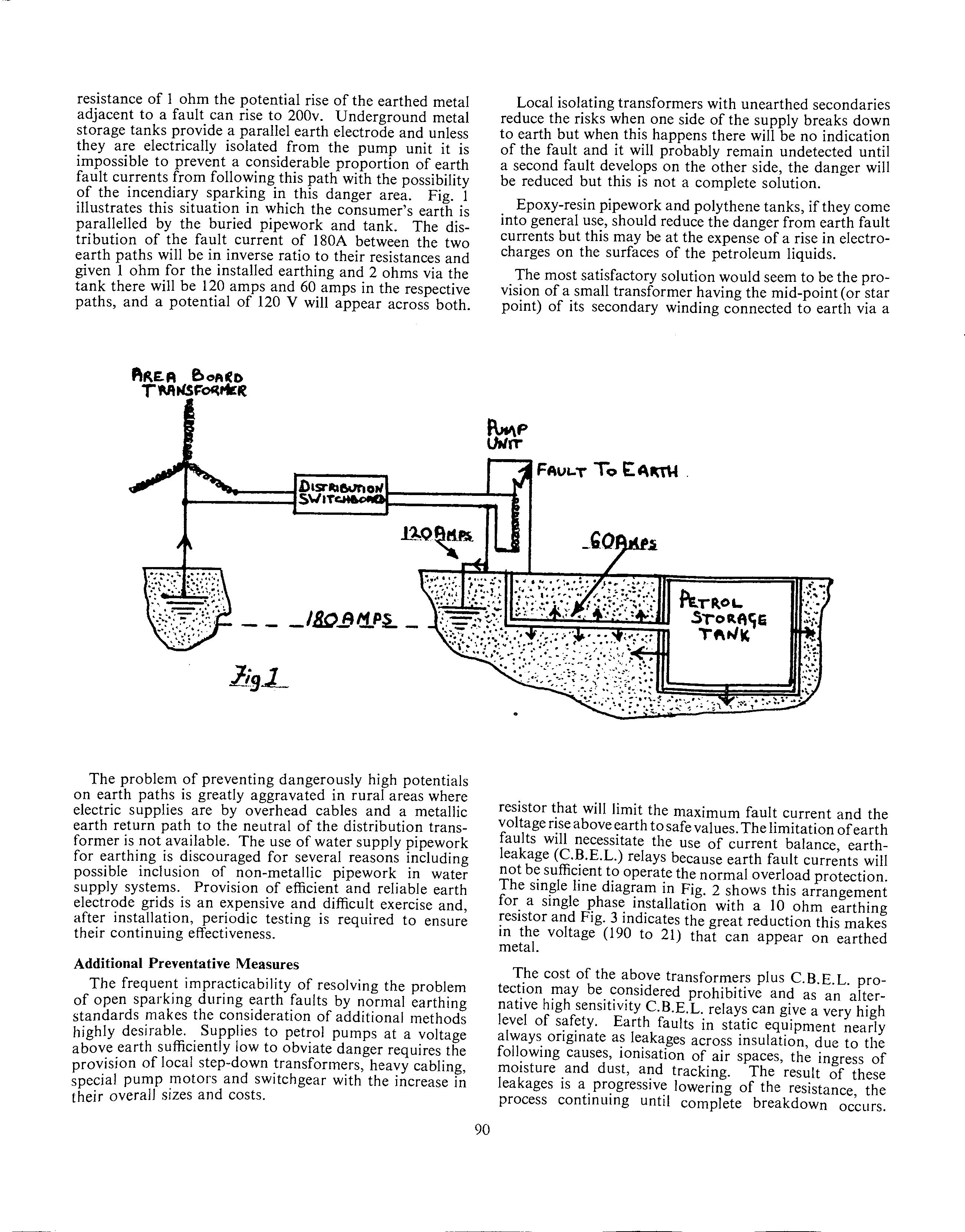
resistance of I ohm the potential rise of the earthed metal adjacent to a fault can rise to 200v. Underground metal storage tanks provide a parallel earth electrode and unless they are electrically isolated from the pump unit it is impossible to prevent a considerable proportion of earth fault currents from following this path with the possibility of the incendiary sparking in this danger area. Fig. I illustrates this situation in which the consumer's earth is parallelled by the buried pipework and tank. The distribution of the fault current of 180A between the two earth paths will be in inverse ratio to their resistances and given 1 ohm for the installed earthing and 2 ohms via the tank there will be 120 amps and 60 amps in the respective paths, and a potential of 120 V will appear across both.
The problem of preventing dangerously high potentials on earth paths is greatly aggravated in rural areas where electric supplies are by overhead cables and a metallic earth return path to the neutral of the distribution transformer is not available. The use of water supply pipework for earthing is discouraged for several reasons including possible inclusion of non-metallic pipework in water supply systems. Provision of efficient and reliable earth electrode grids is an expensive and difficult exercise and, after installation, periodic testing is required to ensure their continuing effectiveness.
Local isolating transformers with unearthed secondaries reduce the risks when one side of the supply breaks down to earth but when this happens there wiII be no indication of the fault and it will probably remain undetected until a second fault develops on the other side, the danger will be reduced but this is not a complete solution.
Epoxy-resin pipework and polythene tanks, if they come into general use, should reduce the danger from earth fault currents but this may be at the expense of a rise in electrocharges on the surfaces of the petroleum liquids.
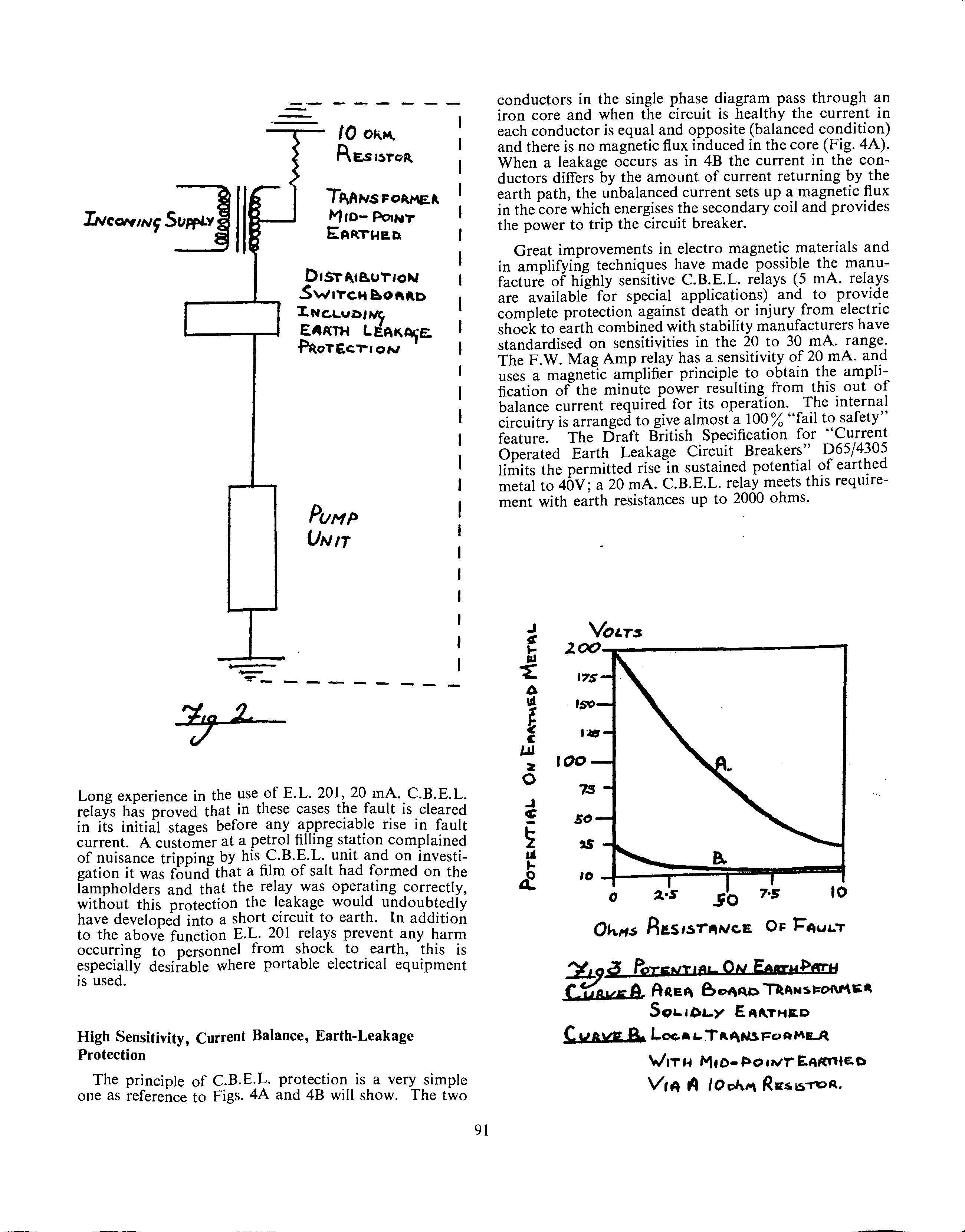
The most satisfactory solution would seem to be the pro-vision of a small transformer having the mid-point (or star point) of its secondary winding connected to earth via a
resistor that will limit the maximum fault current and the voltage rise above earth to safe values. The limitation of earth faults will necessitate the use of current balance earthJeakage (C.B.E.L.) relays because earth fault curr;nts will not b~ suffic!ent t? opera~e the normal overload protection. The sm~le !me diawam m Fig. 2 shows this arrangement for. a smgle J?has~ m.stallation with a 10 ohm earthing resistor and Fig. 3 mdicates the great reduction this makes in the metal. voltage (190 to 21) that can appear on earthed
Additional Preventative Measures
The frequent impracticability of resolving the problem of open sparking during earth faults by normal earthing standards makes the consideration of additional methods highly desirable. Supplies to petrol pumps at a voltage above earth sufficiently low to obviate danger requires the provision of local step-down !ransform~rs, hea~y cablin~, special pump !notors and switchgear with the mcrease m their overall sizes and costs.
T.he cost of the ab<;>ve transformers plus C.B.E.L. pro-tect.10n !11-ay be. ~o!1sidered prohibitive and as an alternative high sens1t1v1ty C.B.E.L. relays can give a very high level of s~f~ty. Earth faults in static equipment nearly always ongmate as leakages across insulation due to the foll?wing causes, ionisation of air spaces, th~ ingress of moisture .and dust, ai:id tracking. The result of these leakages 1s a. pr?gress1v~ lowering of the resistance, the process contmumg until complete breakdown occurs.
90
TPiANS FOIU'\EP. M1D-PosN'T E:AA.Tl-!ltD.
D1ST~1e.uT10N
Sw1Tc.tt e.ofl\AD
'X-NC.L.Utll~ EAIUH LEA~Ari°E: ~0T£c;'T"1 ON
PuHP
UNIT
conductors in the single phase diagram pass through an iron core and when the circuit is healthy the current in each conductor is equal and opposite (balanced condition) and there is no magnetic flux induced in the core (Fig. 4A). When a leakage occurs as in 4B the current in the conductors differs by the amount of current returning by the earth path, the unbalanced current sets up a magnetic flux in the core which energises the secondary coil and provides the power to trip the circuit breaker.
Great improvements in electro magnetic materials and in amplifying techniques have made possible the manufacture of highly sensitive C.B.E.L. relays (5 mA. relays are available for special applications) and to provide complete protection against death or injury from electric shock to earth combined with stability manufacturers have standardised on sensitivities in the 20 to 30 mA. range. The F.W. Mag Amp relay has a sensitivity of 20 mA. and uses a magnetic amplifier principle to obtain the fication of the minute power resulting from this ampliout of balance current required for its operation. The internal circuitry is arranged to give almost a 100 % "fail to safety" feature. The Draft British Specification for "Current Operated Earth Leakage Circuit Breakers" D65/4305 limits the permitted rise in sustained potential of earthed metal to 40V; a 20 mA. C.B.E.L. relay meets this requirement with earth resistances up to 2000 ohms.
Long experience in the use of E.L. 201, 20 mA. C.B.E.L. relays has proved that in these cases the fault is cleared in its initial stages before any appreciab~e rise in fault current. A customer at a petrol filling stat10n complained of nuisance tripping by his C.B.E.L. unit and on investigation it was found that a film of salt had formed on the la!11pholders and that the relay was operating correctly, without this protection the l~ak~ge would undoubtedly have developed into a short ClfCU!t to earth. In addition to the above function E.L. 201 relays prevent any harm occur_ring to personnel from shock to earth, this is especially desirable where portable electrical equipment is used.
High Sensitivity, Current Balance, Earth-Leakage Protection
The principle of C.B.E.L. protection is a very simple one as reference to Figs. 4A and 4B will show. The two
91
.J
~ t
VOLTS 200
0 ul
17$
l
c
l.JJ
2 0
I :.IS
too
7.S
~ c
so
~ u ...
u
10
a
0 :l•S ~o
7•S 10
cy&vg e_ A~E~ f>Of\~ °nANSt:oN"\li'."
So1..10LY E.A"-THltD
Cuava B. Loc:.a1... Tkll-\i~Fc>AME.A
V1T H Mt o- ~o 1 wr E~t(TltE. D v," ,q /Ooh"" R1u.~-R>R.
%.L_,. +a Ciccwx HEALTHY
I I
_______ _J
Jll

I I ---- I
The limits of safety in mA. sec at various in.tensities derived from Professor Charles Dalziel's equation. (see below), the limited shock exposures and the margm of
safety provided by F.W. Mag Amp relays appear in the following table:
Shock Intensity Limits of Safety Shock Exposure E.L. 201 Margin of Safety mA. Dalziel mA. sec. Relay mA. sec. Times (A) (B) 25 50 100 500 1090 545 272 54.25 1.4 2.8 2.7 11.0 778 194 100 4.9
Dangerous Shock Currents
The resistance of the human body may vary considerably depending on the thickness of the skin, its moisture content and its impregnation by conducting matter. Resistances of over 25000 ohms are common and at this value the victim will be able to release himself and though he will sustain an unpleasant shock it will be harmless. A great deal of practical investigation has been devoted to "Let go" values of shock current and it has been established that the mean for men is 16 mA. and 10.5 mA. for women. Current passing through the skin causes it to sweat and blister, rapidly reducing its resistance, and if the shock is sufficiently prolonged the resistance of a body may fall to a minimum of about 500 ohms. Since the current passing through the body is determined by the voltage applied to it divided by its resistance it will be seen that shock intensities of less than I 0 mA. to about 500 mA. may occur.
It is generally agreed that shock currents below 25 mA. are not dangerous; the "Record of Proceedings" of a meeting of experts on electrical accidents at the Inter-
92


