TRIBHUVAN UNIVERSITY

INSTITUTE OF ENGINEERING
KATHMANDU ENGINEERING COLLEGE
INTER-CITY BUS TERMINAL AT BANEPA
By AAKASH BHOCHHIBHOYA 69001
A THESIS SUBMITTED
IN PARTIAL FULFILLMENT OF THE REQUIREMENTS FOR THE DEGREE OF BACHELOR OF ARCHITECTURE
DEPARMENT OF ARCHITECTURE
KATHMANDU, NEPAL
December, 2017
CERTIFICATE
This is to certify that this thesis entitled “Inter-city Bus Terminal” at Banepa, Kavre, Nepal submitted by Mr. Aakash Bhochhibhoya (2069/BAE./001) has been examined and it has been declared successful for the partial fulfillment of the academic requirement towards the completion of the Degree of Bachelor of Architecture.
Lect. Sweta Shrestha (Thesis Supervisor)
Date: December, 2017
Department of Architecture
Institute of Engineering
Kathmandu Engineering College
Tribhuvan University
DECLARATION
I declare that this thesis has not been previously accepted in substance for any degree and is not being concurrently submitted in submission for any degree. I state that this thesis is the result of my own independent work/ investigation, except where otherwise stated. I hereby give approval for my thesis, to be available for photocopying and understanding that any reference to or quotation from my thesis will receive an acknowledgement.
Aakash Bhochhibhoya (2069/BAE/001)
Date: December, 2017
……..….………………
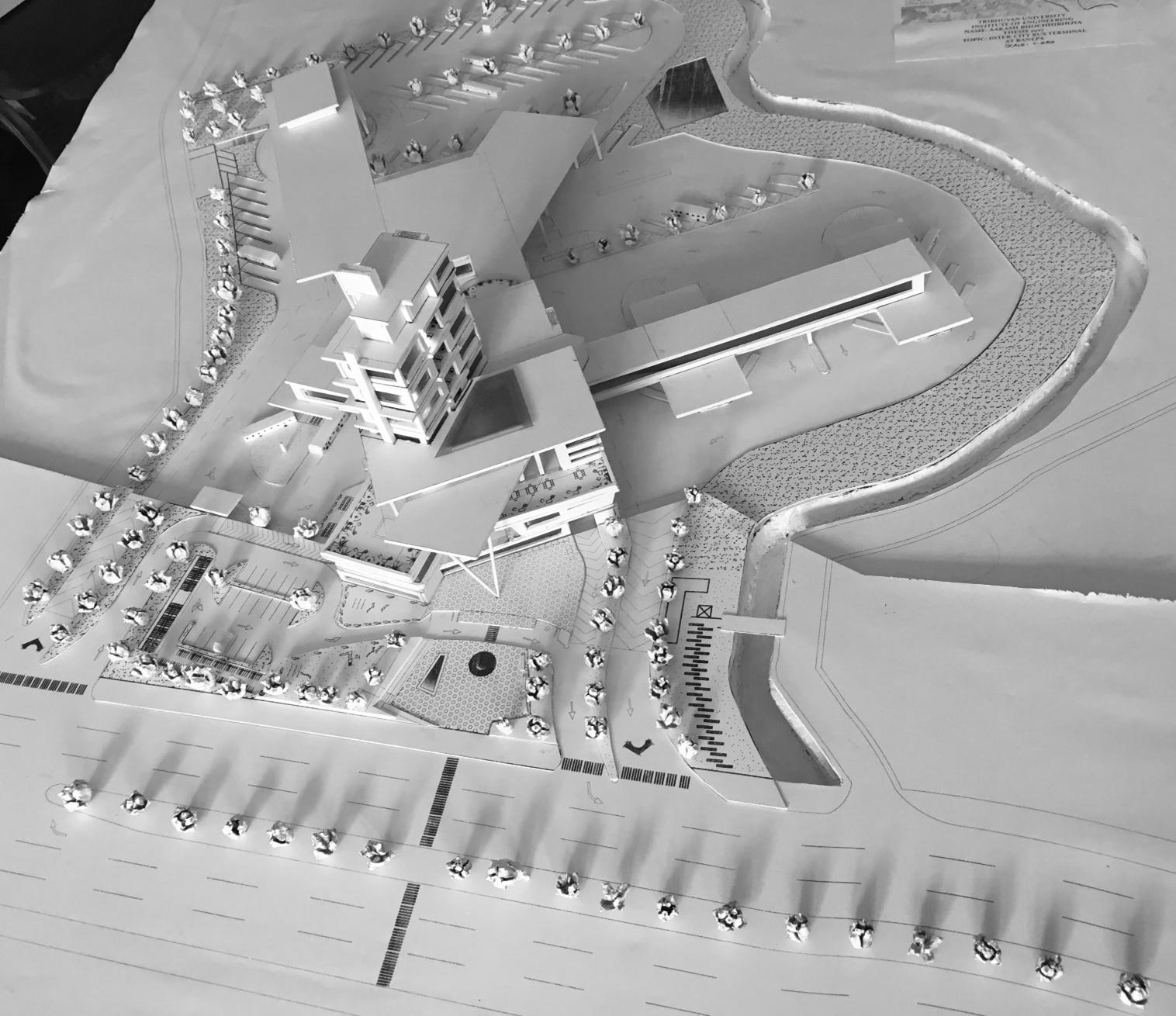
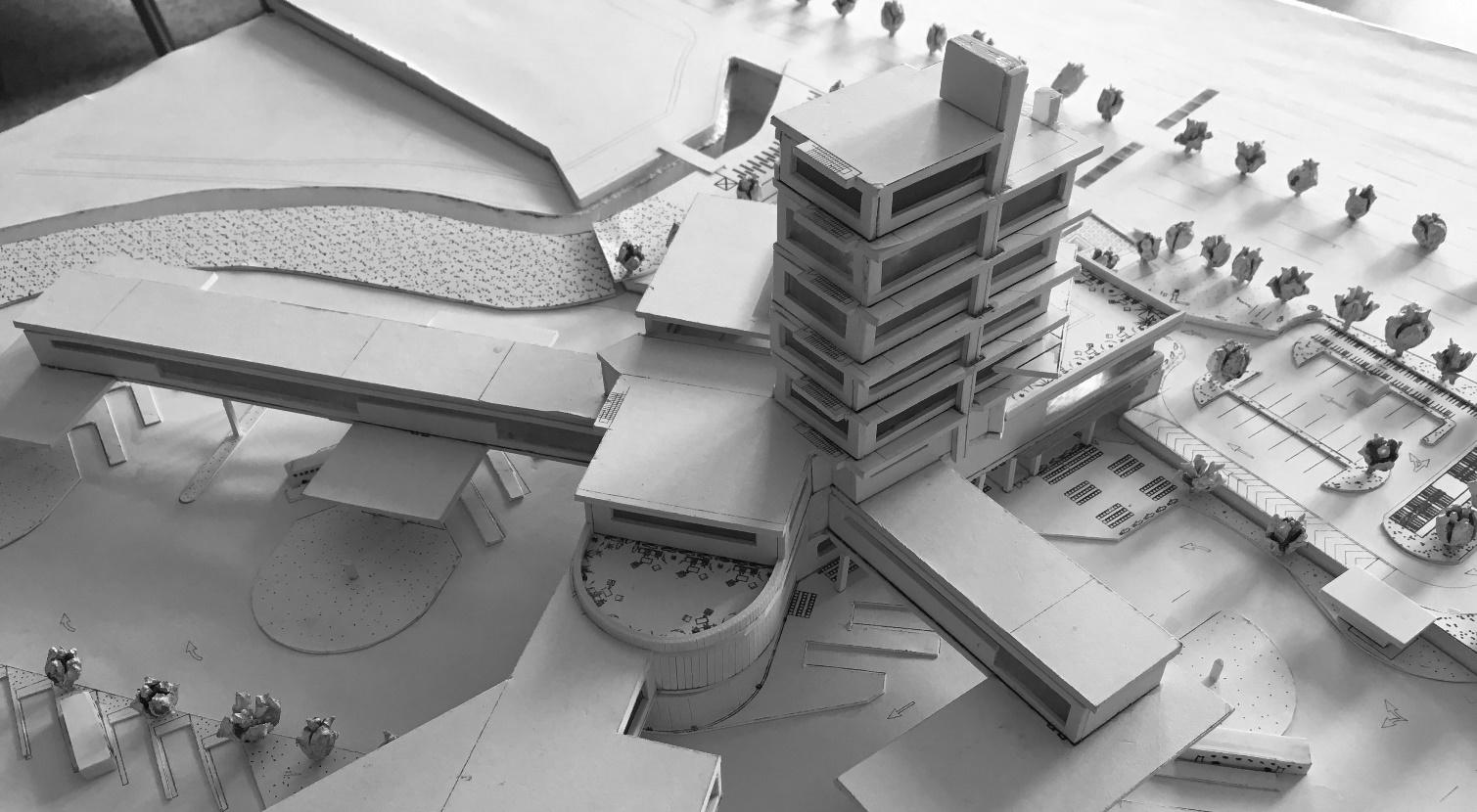
MODEL
THESIS (V/II)
INTER-CITY BUS TERMINAL AT BANEPA:
Submitted by
Name : Aakash Bhochhibhoya

Roll : 69001
Date : (September/2017)
Kathmandu Engineering College Department of Architecture TRIBHUVAN UNIVERSITY
ABSTRACT
As the central hub for employment, business, education and district administration, Banepa is attracting a continuous flow of people from nearby rural area. Burdened with a rapid population growth and haphazard town expansion, transport sector through Banepa depicts a situation where the gap between the transportation needs and provision is continuously widening. This situation has been worsened as road transport is the only alternative for most locations. Similarly, the existing bus park is not catering the passengers’ proper needs. As bus transportation has expanded, there is yet much to be accomplished before it can begin to alleviate the daily mass movement problem. The atmosphere surrounding bus transportation has been that of an inferior and despised method of travel. Bus transportation must be made attractive enough to induce great numbers of persons. An important step in this direction would be the development of a bus terminal of inherently fine architectural quality and urban relationship.
Banepa bus station is the only route to connect the rural areas of eastern side of Kavre. The road expansion project is in the process. Present bus station is not properly designed. It is a central hub for employment, business and education
This thesis proposes a Bus Terminal to serve the suburban and long distance bus needs of Banepa Valley in the area from which increased future needs have been estimated. It would include a study of present transportation statistics and the need for a bus terminal leading into eastern side of Nepal through Banepa as well as to the capital city Kathmandu, and developing therefrom an appropriate architectural solution: a solution enhancing the urban center and in a measure facilitating the daily mass-movement in and outside the valley. The commercial zone would include restaurants, shops and concessions, facilities for the convenience of the travelers and the financial well-being of the terminal.
When designing a station, it is important to consider both the immediate context, and also the city as a whole because transit stop is both ‘node in a network and a place in a city’. This duality challenges transit nodes not only to be places in their own right, but also to act as part of a stitch of a larger design concept for the city. The bus terminal design would also help shift CBD and traffic and other activities demand to outlying location, thereby freeing urban space for other uses, reduce traffic on existing roads, and provide convenient access to outlying bus stations. The building would be a landmark for the city that will strengthen the economic stability created by the existing tourism, thus achieving a booming metropolitan area and promoting environmental awareness.
Thus, ‘Inter-city Bus Terminal at Banepa’ is a project which envisions the bus station as a true time based public space, a place which simultaneously acts as dynamic transportation node within the city’s infrastructural system and a public arena, changing through day and night and made for the comfort and pleasure of the passengers
i
ACKNOWLEDGEMENTS
I would like to express my sincere gratitude to Asso. Prof. Ar Kailash Shrestha, Head of Department and Senior Lecturer Sweta Shrestha, Thesis supervisor, Kathmandu Engineering College for providing valuable guidance and support. Their valuable suggestions always helped me to handle the challenges and their appreciation for good work always kept motivating me to do much better.
I want to further acknowledge the Department of Architecture, Kathmandu Engineering College and all the faculty members, for their help during my research and design for the study and design development phase of the thesis.
I would also like to thank all the staff at Banepa Yatayat Samity for their invaluable support, guidance and hospitality. The information provided by the office has been essential in course of the study.
Last but not the least; I am thankful to Pratik Lohani, Shichhya Shakya, Bikku Shrestha, Anish Bhusal, Bhasan Gurung, Anoj Regmi, Luzza Manandhar, Shashwat Sharma and all, who lent their help during the thesis. I will always cherish their support, guidance and encouragement that bolster me to achieve my goal.
ii
iii TABLE
CONTENTS ABSTRACT i ACKNOWLEDGEMENTS .................................................................................................... ii LIST OF FIGURES xii LIST OF TABLES .............................................................................................................. xx 1 1. INTRODUCTION .......................................................................................................... 2 1.1. BACKGROUND 2 1.2. OVERVIEW ........................................................................................................... 4 1.2.1. TERMINALS VERSUS STATION 5 1.2.2. TERMINALS AND STATIONS ARE IMPORTANT ELEMENTS 5 1.3. PROJECT INTRODUCTION 5 1.4. JUSTIFICATION AND IMPORTANCE OF THE PROJECT 6 1.5. FEASIBILITY AND SCOPES 7 1.6. CHALLENGES 7 1.7. GOALS AND OBJECTIVES .................................................................................. 7 1.8. SITE AND OTHER LOCATION INFORMATION 8 1.9. EXPECTED OUTPUT 9 1.9.1. THEORETICAL UNDERSTANDING AND RESEARCH FINDINGS 9 1.9.2. PROJECT PLANNING, DESIGN AND DRAWING 9 1.10. METHODOLOGY 9 1.11. LITERATURE STUDY / CASE STUDY / FIELD STUDY / RESEARCH 10 1.11.1. LITERATURE STUDY 10 1.11.2. NATIONAL CASE STUDY 10 1.11.3. REGIONAL CASE STUDIES 11 1.11.4. INTERNATIONAL CASE STUDIES 11 1.11.5. OTHER AMENITIES CASE STUDIES 11 1.12. REQUIREMENTS OF THE PROJECT ............................................................... 11 1.13. WORK FLOW 12 2. LITERATURE REVIEW 14
OF
iv 2.1. BUS TERMINAL 14 2.1.1. ROAD BASED BUS STOP 16 2.1.2. ROAD SIDE BUS BAY ................................................................................. 16 2.1.3. LOCAL BUS TERMINAL 17 2.1.4. INTER-CITY BUS TERMINAL AND INTER-STATE BUS TERMINAL (ISBT) 17 2.2. SUSTAINABILITY ............................................................................................... 18 2.3. URBAN DESIGN 18 2.4. RELATIONSHIP BETWEEN URBAN DESIGN AND SUSTAINABILITY ............ 19 2.5. SUSTAINABLE URBAN DESIGN 20 2.6. SUSTAINABLE URBAN DEVELOPMENT 21 2.6.1. BUS TERMINAL’S ROLE IN SUSTAINABLE URBAN DESIGN .................. 22 2.7. HISTORY 24 2.7.1. HISTORY (WORLD) .................................................................................... 24 2.7.2. HISTORY (NEPAL) 24 2.8. FUNDAMENTAL PHIOSOPHICAL ISSUES ....................................................... 24 2.9. PLANNING CRITERIA 25 2.9.1. NEED ........................................................................................................... 26 2.9.2. SIZE 29 2.9.3. LOCATION ................................................................................................... 30 2.9.4. DESIGN 32 2.10. CIRCULATION AND PARKING PATTERN OF VEHICLE .................................. 33 2.10.1. VEHICULAR STANDARDS 33 2.11. BUS BERTHS ..................................................................................................... 34 2.12. RAMPING 35 2.13. TURNING RADIUS FOR DIFFERENT TURNING SITUATIONS ........................ 36 2.14. POSITIONING OF BUS TERMINAL BUILDING IN RELATION TO BUS TURNING LOOP 36 2.15. PASSENGERS FLOW PATTERN AND THEIR NEEDS ..................................... 36 2.15.1. OBJECTIVES 36 2.16. PASSENGER CIRCULATION ............................................................................. 37
v 2.16.1. CIRCULATION PLANNING 37 2.16.2. CIRCULATION STANDARDS 37 2.16.3. PLANNING FOR SAFETY AND SECURITY 40 2.16.4. PASSENGER CIRCULATION & ACCESS – BOARDING ROUTE, BUS PLATFORM, DROP – OFF ........................................................................................ 40 2.17. FUNCTIONAL ELEMENTS AND PLANNING CRITERIA 41 2.17.1. TERMINAL BUILDING SPACE REQUIREMENTS ...................................... 41 2.17.2. SUPPORT FACILITIES 42 2.18. ARCHITECTURAL CHARACTER ....................................................................... 47 2.19. TRANSIT ORIENTED DEVELOPMENT 48 2.19.1. TOD IN DIFFERENT CITIES IN WORLD .................................................... 49 2.19.2. EQUITY AND HOUSING COST CONCERNS 49 2.20. PARK AND RIDE FACILITIES ............................................................................ 50 2.20.1. BENEFITS AND CRITICISM 50 2.20.2. THE DIFFERENT TYPES OF PARK AND RIDES ARE .............................. 51 2.21. FUNCTIONAL TECHNOLOGICAL ISSUES 53 2.21.1. TECHNIQUES FOR COMMUNICATING WITH PERSONS WITH DISABILITIES 53 2.21.2. DESIGNING FOR DISABLES 58 2.22. ENVIRONMENT AND ENERGY CONSIDERATIONS 62 2.22.1. GREEN ARCHITECTURE 62 2.22.2. GREEN MATERIALS (GREEN CONCRETE) 66 2.22.3. GREY WATER TREATMENT 69 2.22.4. GREASE WATER TREATMENT 69 2.22.5. USE OF RENEWABLE ENERY: SOLAR ENERGY (PV CELL) .................. 70 2.22.6. RAINWATER HARVESTING 70 2.22.7. ATRIUM ....................................................................................................... 72 2.22.8. POROUS PAVEMENT 74 3. CASE STUDY ............................................................................................................ 76
vi 3.1. CASE STUDY 1 : CURITIBA, BRAZIL 77 3.1.1. GENERAL INFORMATION 77 3.1.2. BACKGROUND ........................................................................................... 78 3.1.3. ENVIRONMENTALLY SUSTAINABLE URBANIZATION 79 3.1.4. ECONOMICALLY SUSTAINABLE URBANIZATION 80 3.1.5. SOCIAL SUSTAINABLE URBANIZATION 80 3.1.6. GOVERNANCE AND INSTITUTIONAL SUSTAINABLE URBANIZATION 81 3.1.7. CURITIBA’S TRANSPORTATION SYSTEM ............................................... 81 3.1.8. SOLVING THE FARE PROBLEM 84 3.1.9. SECURITY ................................................................................................... 84 3.1.10. BUS AND STATION DESIGN 85 3.1.11. ANALYSIS.................................................................................................... 86 3.2. CASE STUDY 2 : GONGABU BUS PARK 88 3.2.1. GENERAL INFORMATION .......................................................................... 88 3.2.2. SURROUNDING CONTEXT 88 3.2.3. HISTORICAL BACKGROUND ..................................................................... 89 3.2.4. IMPACT 89 3.2.5. SICIO-ECONOMIC ASPECTS ..................................................................... 89 3.2.6. ECONOMIC ACTIVITIES INSIDE BUS PARK 90 3.2.7. ECONOMIC ACTIVITES OUTSIDE BUS PARK 91 3.2.8. SOCIO-CULTURAL VALUE 91 3.2.9. ARCHITECTURAL EXPRESSION 91 3.2.10. PLANNING AND CIRCULATION 92 3.2.11. AREA/CAPACITY 92 3.2.12. BUS TERMINAL AND ITS DIFFERENT UNITS .......................................... 92 3.2.13. ACCESS 93 3.2.14. TERMINAL BUILDING ................................................................................. 93
vii 3.2.15. TERMINAL MANAGEMENT OFFICE 93 3.2.16. SECURITY 94 3.2.17. INFORMATION AND COMMUNICATIONS 94 3.2.18. TOILETS 94 3.2.19. WATER SUPPLY 95 3.2.20. WAITING AREA ........................................................................................... 95 3.2.21. TICKETING 96 3.2.22. UNDER CONSTRUCTION .......................................................................... 96 3.2.23. OTHER FACILITIES 97 3.2.24. ARRIVAL BERTH ......................................................................................... 97 3.2.25. DEPARTURE BERTH 98 3.2.26. LONG TERM PARKING LOT ....................................................................... 98 3.2.27. AUTOMOBILE CARE CENTRE (AMC) 99 3.2.28. LISTS OF ROUTES PROVIDED 100 3.2.29. ANALYSIS 102 3.3. CASE STUDY 3 : BHARATPUR BUS TERMINAL, BHARATPUR 103 3.3.1. GENERAL INFORMATION 103 3.3.2. PLANNING AND CIRCULATION 103 3.3.3. TERMINAL BUILDING 103 3.3.4. ARRIVAL AND DEPARTURE BERTH 103 3.3.5. INFRASTRUCTURE AND SEREVICES 106 3.3.6. DESIGN ELEMENT AND STRUCTURE 107 3.3.7. ANALYSIS.................................................................................................. 107 3.4. CASE STUDY 4 : GSRTC BUS PORT, GEETA MANDIR, AHMENDABAD 108 3.4.1. GENERAL INFORMATION ........................................................................ 108 3.4.2. SURROUNDING CONTEXT 109 3.4.3. HISTORICAL BACKGROUND ................................................................... 110
viii 3.4.4. IMPACT 111 3.4.5. SOCIO-ECONOMIC CHARACTERISTICS 111 3.4.6. ECONOMIC ACTIVITIES 112 3.4.7. SOCIO-CULTURAL VALUE 113 3.4.8. ARCHITECTURAL EXPRESSION 113 3.4.9. PLANNING AND CIRCULATION ............................................................... 114 3.4.10. AREA / CAPACITY 115 3.4.11. BUS PORT AND ITS DIFFERENT UNITS ................................................. 115 3.4.12. ACCESS 116 3.4.13. SECURITY ................................................................................................. 117 3.4.14. TICKETING, INFORMATION AND COMMUNICATIONS 117 3.4.15. PUBLIC WASHROOMS ............................................................................. 118 3.4.16. WATER SERVICE 118 3.4.17. WAITING AREA 118 3.4.18. OTHER FACILITIES 119 3.4.19. ARRIVAL AND DEPARTURE BERTH 119 3.4.20. AUTOMOBILE CARE CENTRE (AMC) ..................................................... 120 3.4.21. ANALYSIS 120 3.5. CASE STUDY 5 : ISBT KASHMERE GATE, NEW DELHI ............................... 121 3.5.1. GENERAL INFORMATION 121 3.5.2. DESIGN PRINCIPLES 121 3.5.3. SITE ACCESS 122 3.5.4. SITE PLAN ................................................................................................. 122 3.5.5. SITE PROGRAM 123 3.5.6. MATERIALS ............................................................................................... 124 3.5.7. PLANNING 124 3.5.8. ANALYSIS.................................................................................................. 127
ix 3.5.9. INFERENCES 127 3.6. CASE STUDY 6 : SUVARNABHUMI AIRPORT, BANGKOK 128 3.6.1. GENERAL INFORMATION ........................................................................ 128 3.6.2. STRUCTURAL ANALYSIS 128 3.6.3. INFERENCE 131 3.7. COMPARATIVE ANALYSIS 132 134 4. INFERENCE 135 136 5. PROGRAM FORMULATION .................................................................................... 137 5.1. AREA ANALYSIS 137 5.2. AREA CALCULATION 141 145 6. SITE STUDY 146 6.1. SITE SELECTION BASIS 146 6.2. SITE JUSTIFICATION 147 6.2.1. EXISTING BUS STATION CONDITION AND ROUTES ............................ 147 6.2.2. CASE STUDY ON EXISTING BANEPA BUS STATION 148 6.3. SITE ANALYSIS 150 6.3.1. SITE INTRODUCTION 150 6.3.2. ACCESS AND APPROACH ....................................................................... 150 6.3.3. EXISTING SURROUNDIGNS 150 6.3.4. SOCIETY AND CULTURE 150 6.3.5. TOPOGRAPHY AND LANDFORM 151 6.3.6. VEGETATION 151 6.3.7. HYDROLOGY 151 6.3.8. INFRASTRUCTURES 151 6.3.9. SOIL CONDITION ...................................................................................... 151 6.3.10. VISUAL POTENTIAL 151 6.3.11. LEGAL ASPECT (BY – LAWS) .................................................................. 151
x 6.3.12. CLIMATIC ANALYSIS 152 6.4. SITE IMAGES 153 6.5. SITE DRAWING ................................................................................................ 156 6.6. SWOT ANALYSIS 156 6.6.1. STRENGTH ............................................................................................... 156 6.6.2. WEAKNESS 157 6.6.3. OPPORTUNITIES ...................................................................................... 157 6.6.4. THREAT 157 7. DESIGN CONCEPT AND DESIGN DEVELOPMENT PROCESS 159 7.1. CONCEPT 159 7.2. DESIGN INSPIRATION ..................................................................................... 160 7.3. DEVELOPMENT OF MASTERPLAN AND FORM 161 7.3.1. SITE DEVELOPMENT ............................................................................... 161 7.3.2. ZONING 162 7.3.3. ARCHITECTURAL DESIGN CONCEPT .................................................... 164 7.4. DESIGN FEATURES AND SUMMARY 167 8. BUILDING SERVICES ............................................................................................. 170 8.1. WATER SERVICES 170 8.2. SANITATION ..................................................................................................... 171 8.2.1. SIZE OF SEPTIC TANK 171 8.2.2. GREASE WATER TREATMENT ............................................................... 171 8.2.3. REED BED PLANT 172 8.3. STORM WATER MANAGEMENT ..................................................................... 172 9. STRUCTURE 174 9.1. FOUNDATION 174 9.2. COLUMN 174 9.3. WAFFLE SLAB 175 9.4. TRUSS .............................................................................................................. 175 9.5. MULTI-STOREY LONG SPAN STRUCTURE 175 9.6. EXPANSION JOINT .......................................................................................... 176 9.7. RETAINING WALL 176
xi 10. CIRCULATION 178 10.1. RAMP 178 10.2. STEPS............................................................................................................... 178 10.3. LIFTS 178 10.4. ESCALATORS .................................................................................................. 178 11. APPROACH FOR SUSTAINABLE DESIGN 180 11.1. BUILDING ORIENTATION ................................................................................ 180 11.2. BUILT FORM 180 11.3. ROOF GARDENING 181 11.4. ATRIUM 181 11.5. WALL AND WINDOW OPENINGS 182 11.6. PASSIVE SHADING DEVICES ......................................................................... 182 11.7. RAIN WATER HARVESTING 183 11.8. BUILDING INTEGRATED PHOTOVOLTAIC 184 11.9. CONSTRUCTION MATERIAL 186 11.10. GREENARY 186 12. CONCLUSION ...................................................................................................... 188 13. BIBLIOGRAPHY 190 193
LIST OF FIGURES
xii
Figure 1-1 : Project methodology....................................................................................... 10 Figure 1-2 : Work flow diagram 12 Figure 2-1 : Bus Terminal 14 Figure 2-2 : Diagram of a Kerbside bus stop with parking either side for a single ‘standard’ 13.5m long tag axle bus 16 Figure 2-3 : Diagram of a fully indented bus bay for a single ‘standard’ 13.5m long tag axle bus 16 Figure 2-4 : Local bus terminal 17 Figure 2-5 : Inter-city bus terminal and inter-state bus terminal (ISBT) 17 Figure 2-6 : Sustainable urban design 20 Figure 2-7 : Global greenhouse gas emissions by economic sector (2014) ...................... 22 Figure 2-8 : Evolution of surviving vehicle fleet (‘000) in the Kathmandu valley ................ 22 Figure 2-9 : Sustainable urban form and transport 23 Figure 2-10 : General flow in a bus terminal 26 Figure 2-11 : Access hierarchy 27 Figure 2-12 : Natural surveillance reduces opportunities for crime without target hardening ........................................................................................................................................... 28 Figure 2-13 : Station area influence zones ........................................................................ 30 Figure 2-14 : Design perspective of bus terminal building and its surrounding 32 Figure 2-15 : Motorcycle 33 Figure 2-16 : Bicycle 33 Figure 2-18 : Car 34 Figure 2-17 : Micro bus ...................................................................................................... 34 Figure 2-19 : Bus ............................................................................................................... 34 Figure 2-20 : Types of Berth Loading 35 Figure 2-21 : Saw tooth loading 35 Figure 2-22 : Ramping 35 Figure 2-23 : Turning radius for different turning situations 36
xiii Figure 2-24 : Bus terminal building in relation to bus turning loop 36 Figure 2-25 : Staircase width 38 Figure 2-26 : General specification for selection of lift 38 Figure 2-27 : Elevator details 39 Figure 2-28 : Escalator details ........................................................................................... 40 Figure 2-29 : General plan of Maintenance Center ........................................................... 42 Figure 2-30 : General plan of Filling Station 43 Figure 2-31 : Module for a square table to be arranged in a rectangular pattern 45 Figure 2-32 : Module for a square table to be arranged in a diagonal pattern 45 Figure 2-33 : Transit oriented development 48 Figure 2-34 : Park and ride pattern in Curitiba, Brazil ........................................................ 50 Figure 2-35 : Park and ride lot adjacent to the MTADongan Hills railway ......................... 52 Figure 2-36 : A busy bike-and-ride facility at a Miami Metrorail heavy-rail station. 52 Figure 2-37 : Tactile maps 54 Figure 2-38 : Tactile Pathways and Detectable Warnings 55 Figure 2-39 : Smart Cards 57 Figure 2-40 : Automatic Vehicle Location 57 Figure 2-41 : Suggested international signs for accessibility ............................................. 58 Figure 2-42 : General anthropometric data’s for wheel chair ............................................. 58 Figure 2-43 : General anthropometric data’s for disable Users 59 Figure 2-44 : Different layouts of ramp 59 Figure 2-45 : Slope for disabled 60 Figure 2-46 : Parking requirement for different angles 60 Figure 2-47 : Parking using end lot access........................................................................ 61 Figure 2-48 : Parking area for wheel chair users ............................................................... 61 Figure 2-49 : Barriers with vertical gardening 64 Figure 2-50 : Lawn lattices on parking’s 64 Figure 2-51 : Ventilating chambers 65
xiv Figure 2-52 : Multipurpose shelter 65 Figure 2-53 : Power saving lights 66 Figure 2-54 : Ventilated faces with vertical gardening 66 Figure 2-55 : Types of green concrete to reduce the carbon content in the conventional 68 Figure 2-56 : Grey water treatment plant ........................................................................... 69 Figure 2-57 : Grease water treatment plant ....................................................................... 69 Figure 2-58 : Solar energy systems 70 Figure 2-59 : Roof catchment system 71 Figure 2-60 : Domestic rain water harvesting 71 Figure 3-1 : Bus Station, Curitiba, Brazil 77 Figure 3-2 : Map of Curitiba, Brazil .................................................................................... 78 Figure 3-3 : Sustainable transportation of Curitiba ............................................................ 79 Figure 3-4 : Bus lines chosen over Subway in Curitiba 81 Figure 3-5 : Curitiba city map showing bus routes 82 Figure 3-6 : Paying fare inside Tube like structure, Curitiba 84 Figure 3-7 : Transparent glass tube station, Curitiba 84 Figure 3-8 : Exiting and boarding in the bus, Curitiba 85 Figure 3-9 : Direct exit from boarding tube ........................................................................ 85 Figure 3-10 : Lift situated for disabled passengers, strollers and heavy bags ................... 86 Figure 3-11 : Inside tube station 86 Figure 3-12 : Cross section of bus way and service roads 87 Figure 3-13 : Bus terminal to close proximity of building density 87 Figure 3-14 : View from entrance, Gongabu bus terminal 88 Figure 3-15 : Retail shops and Kantipur mall ..................................................................... 90 Figure 3-16 : Activities outside bus park ............................................................................ 91 Figure 3-17 : Master of Gongabu bus terminal; Refer annex 92 Figure 3-18 : Terminal management office 93 Figure 3-19 : Metropolitan police office 94
xv Figure 3-20 : Public toilet block 94 Figure 3-21 : Overhead water tank 95 Figure 3-22 : Waiting area 95 Figure 3-23 : Ticket counters 96 Figure 3-24 : Under construction Terminal Building .......................................................... 96 Figure 3-25 : Under construction Mall ................................................................................ 96 Figure 3-26 : Arrival berth 97 Figure 3-27 : Departure berth 98 Figure 3-28 : Long term parking lot 98 Figure 3-29 : Automobile Care Centre 99 Figure 3-30 : Washing bays (left) & maintenance bays (right) ........................................... 99 Figure 3-31 : View from entrance, Bharatpur bus park .................................................... 103 Figure 3-32 : Eatery 104 Figure 3-33 : Waiting space 104 Figure 3-34 : Public toilet 104 Figure 3-35 : Arrival berth 104 Figure 3-36 : Long term parking 104 Figure 3-37 : Auto-workshop ........................................................................................... 104 Figure 3-38 : Master plan of Bharatpur bus terminal ....................................................... 104 Figure 3-39 : Kiosks 105 Figure 3-40 : Shades outside ticket counter 105 Figure 3-41 : Ground floor plan, terminal building 105 Figure 3-42 : Clock and display board 105 Figure 3-43 : Entrance door ............................................................................................. 105 Figure 3-44 : Ticket counter ............................................................................................. 105 Figure 3-45 : Lobby 105 Figure 3-46 : Waiting area 105 Figure 3-47 : First floor plan 106
xvi Figure 3-48 : Bow string truss above lobby 107 Figure 3-49 : Double storey open semi open lobby 107 Figure 3-50 : Steel structure outside ticket counter as shading device 107 Figure 3-51 : Long span steel structure in long route departure berth 107 Figure 3-52 : View from entrance, Geeta Mandir bus port, Ahmendabad ....................... 108 Figure 3-53 : Population Density, Ahmedabad ................................................................ 109 Figure 3-54 : Location of Old and New bus port 110 Figure 3-55 : Old Geeta Mandir bus port, Ahmedabad 110 Figure 3-56 : Unmanaged platform arrangements on Old Geeta Mandir bus port 110 Figure 3-57 : Commercial complexes; refer annex 8.10 112 Figure 3-58 : 3D view of commercial complex by Town Hub ........................................... 112 Figure 3-59 : Food court and waiting room as social interaction space ........................... 113 Figure 3-60 : Front facade 113 Figure 3-61 : Location Key Plan 114 Figure 3-62 : Geeta Mandir Site Plan, Ahmedabad 114 Figure 3-63 : Ample private vehicles parking space of 4,000 sq. ft. 115 Figure 3-64 : Real time digital display board for bus time detail 115 Figure 3-65 : 25 Boarding platforms ................................................................................ 116 Figure 3-66 : Entry and exit access ................................................................................. 116 Figure 3-67 : CCTV surveillance 117 Figure 3-68 : Ticket counter and information desk 117 Figure 3-69 : Public wash rooms 118 Figure 3-70 : Clean drinking water for public 118 Figure 3-71 : General waiting area .................................................................................. 118 Figure 3-72 : Lighting during night time ........................................................................... 119 Figure 3-73 : Passengers waiting in berth 119 Figure 3-74 : Arrival gate 119 Figure 3-75 : Google plan, ISBT Kashmiri gate 122
xvii Figure 3-76Master plan, ISBT Kashmiri gate 122 Figure 3-77 : 3D images of Parking area, Main entrance Food courts, waiting areas 123 Figure 3-78 : Material used in interior 124 Figure 3-79 : Link block 125 Figure 3-80 : Section of building complex, ISBT Kashmiri gate ....................................... 125 Figure 3-81 : Louver design ............................................................................................. 126 Figure 3-82 : Section showing skylight in departure area 127 Figure 3-83 : Section thru terminal pavilion 129 Figure 3-84 : Roof trellis 129 Figure 3-85 : Super truss system 129 Figure 3-86 : Detail drawing of super truss girder of span 126 m .................................... 130 Figure 3-87 : Indoor space with glazed and translucent material .................................... 130 Figure 3-88 : Concourse A & G typical section 131 Figure 5-1 : Program chart 144 Figure 6-1 : Existing bus station and its surroundings and destinations 147 Figure 6-2 : Bus routes 147 Figure 6-3 : View of bus station 148 Figure 6-4 : Entry and exit ............................................................................................... 148 Figure 6-5 : Waiting space ............................................................................................... 148 Figure 6-6 : Ticket counter 148 Figure 6-7 : Long term parking 148 Figure 6-8 : Vendors 148 Figure 6-9 : Site surroundings and amenities 149 Figure 6-10 : Site and its surroundings ............................................................................ 149 Figure 6-11 : Workshop and repairing shops nearby site ................................................ 149 Figure 6-12 : Access to site 150 Figure 6-13 : Climate graph of Banepa; average min and max temperature 152 Figure 6-14 : Climate table/Historical weather data Banepa 152
xviii Figure 6-15 : Open and flat land 153 Figure 6-16 : Close up of river 154 Figure 6-17 : Ganesh mandir and pedestrian bridge 154 Figure 6-18 : Pulbazar approach road 155 Figure 6-19 : Araniko highway ......................................................................................... 155 Figure 7-1 : Frank Lloyd Wright's Falling Water .............................................................. 160 Figure 7-2 : Santiago Calatrava's Lyon-Satolas TGV Station 160 Figure 7-3 : Landform of the site 161 Figure 7-4 : Site Section 161 Figure 7-5 : Vertical segregation of space 161 Figure 7-6 : Horizontal segregation of space ................................................................... 162 Figure 7-7 : Zoning of the site .......................................................................................... 165 Figure 7-8 : Zoning incorporated with final master plan of bus terminal 165 Figure 7-9 : Conceptual section showing the functions accordingly from lower level to the upper level 166 Figure 7-10 : Circulation around the site 167 Figure 7-11 : Ground floor plan, terminal zone ................................................................ 167 Figure 7-12 : From view from highway ............................................................................ 168 Figure 7-13 : View of accommodation tower 168 Figure 7-14 : Plan of accommodation area 168 Figure 8-1 : Section of Septic tank including Grease water treatment 171 Figure 8-2 : Grease water treatment detail 171 Figure 8-3 : Reed Bed plant............................................................................................. 172 Figure 9-1 : Section of mat foundation ............................................................................. 174 Figure 9-2 : Connection detail (Ball and socket joint) 174 Figure 9-3 : Entrance view 174 Figure 9-4 : Waffle slab detail and lighting fixture 175 Figure 9-5 : Truss detail 175 Figure 9-6 : Multi-storey long span structure detail .......................................................... 176
xix Figure 9-7 : Expansion joint detail 176 Figure 9-8 : Retaining wall detail 176 Figure 10-1 : Ramp of road in ratio 1:10 178 Figure 10-2 : Wheel chair user accessible escalator at angle 300 178 Figure 11-1 : Building orientation ..................................................................................... 180 Figure 11-2 : Diagram of Built form .................................................................................. 180 Figure 11-3 : Perforated green roof for air flow in ideal parking 181 Figure 11-4 : Roof gardening 181 Figure 11-5 : Atrium to gain skylight in waiting area 181 Figure 11-6 : Exterior openings for light and ventilation 182 Figure 11-7 : Courtesy of SBIC and the Beyond Green™ Guidelines for High-Performance Homes ............................................................................................................................. 182 Figure 11-8 : Catchment area 183 Figure 11-9 : Rain water harvesting process 183 Figure 11-10 : Departure wing 184 Figure 11-11 : Electrical energy consumed per annum for different Buildings (Source: IEA 2006)................................................................................................................................ 185 Figure 11-12 : Transparent solar panel prototype 185 Figure 11-13 : Permeable pavers’ treatment 186
xx
Table 1-1 : List of Strategic Road Network - National Highway Roads ............................... 3 Table 3-1 : Curitiba’s system: Lines, busses, capacity, fleet. Source: URBS, 2008 83 Table 3-2 : Lists of the routes provided 100 Table 3-3 : Distribution of Persons by Activity Status 111 Table 5-1 : Area analysis 137 Table 5-2 : Program formulation 142 Table 8-1 : Water demand calculation ............................................................................. 170
LIST OF TABLES
CHAPTER 1

INTER – CITY BUS TERMINAL AT BANEPA
1
Aakash Bhochhibhoya
PROJECT INTRODUCTION
1. INTRODUCTION
1.1. BACKGROUND
Infrastructure is a broad concept linked to every facet of the economy and human life. Accordingly, the list of associated issues is long. For any purposeful analysis of issues in infrastructure development to lead to an action-oriented way forward, it is necessary to narrow down the definition of infrastructure and associated issues. The term infrastructure has been used since 1927 to refer collectively to the roads, bridges, rail lines and similar public works that are required for an industrial economy to function. Transportation, communication, sewage, water and electric systems are all a part of infrastructure. These systems tend to be high-cost investments. In general, infrastructure is location-specific and cannot be moved from place to place 1 .
Transportation infrastructure cannot operate without transportation and transportation cannot run without transportation infrastructure. Different transportations have their own infrastructure to support each other. For air transportation, their infrastructure will be the airport. Port will be the infrastructure for water transportation while infrastructure for land transportation such as public bus will be the bus terminal or bus stop.
Transportation is also an important infrastructure for development. It carries goods and people from one place to another. It is fundamental factor to develop the country as well as industry, agriculture. Nepal is a landlocked country with China to the North and India to the South. Because of its mainly mountainous terrain and difficult weather conditions, roads and aviation are the major modes of transportation in the country. The presence of railways is negligible, and urban transport services are few.
Nepal‘s total road network and density are low and only 43 percent of the population has access to all-weather roads. More than 60 percent of the network is concentrated in the lowland (Terai) areas of the country. Nepal‘s road network annually increased by 6.7% between FY1995/96 and FY2003/04, with the largest expansion occurring in roads classified as "district or rural roads", which grew annually by 11% during this period. 2
1 unescap. (2016). Retrieved from www.unescap.org
2 Department of Roads. (2016, December 1). About Highways of Nepal. Retrieved from Department of Roads: https://www.dor.gov.np/national_highways.php
INTER – CITY BUS TERMINAL AT BANEPA Aakash
2
Bhochhibhoya
Some important road (main high way of Nepal) which is developed in Nepal is follows.
Table 1-1 : List of Strategic Road Network - National Highway Roads
INTER – CITY BUS TERMINAL AT BANEPA
3
Aakash Bhochhibhoya
S.N. Name of Highway Abbr. Length (KM) Node Feature Remarks Start Point End Point 01 Mahendra Rajmarg MRM 1027.6 7 Mechi Bridge, Jhapa Border Gaddachowki Border, Kanchanpur (including 29 Km overlap in TRP) 02 Tribhuvan Rajpath TRP 159.66 Tribhuvan Statue, Tripureshwor Sirsiya Bridge, Birgunj Border 03 Arniko Rajmarg ARM 112.83 Maitighar Junction, KTM Friendship Bridge, Kodari Border 04 Prithvi Rajmarg PRM 173.43 Naubise (TRP) Prithvi Chowk, Pokhara 05 Narayanghat Mugling Rajmarg NMRM 36.16 Pulchowk, Naryanghat Mugling (PRM) 06 Dhulikhel Sindhuli Bhittamod Rajmarg DSRM 198 Bhittamod border, Jaleshwor Dhulikhel (ARM) 135.94 Km. completed 07 Mechi Rajmarg MERM 268.06 Kechana Border, Bhadrapur Taplejung 08 Koshi Rajmarg KRM 111.46 Rani Border, Biratnagar Hile 09 Sagarmatha Rajmarg SARM 265 Kadmaha, Saptari (MRM) Solusalleri Solukhumbu 53.97 Km. completed 10 Siddhartha Rajmarg SRM 181.22 Sunauli Border Prithvi Chowk, Pokhara 11 Rapti Rajmarg PRM 196 Ameliya, Dang (MRM) Musikot, Rukum 168.54 Km Completed 12 Ratna Rajmarg RPM 113.08 Jamuniya Border, Nepalgunj Bangesimal, Surkhet
Source: (Department of Roads, 2016); viewed 1st December, 2016; Department Of Roads
The population of BANEPA valley has been increasing in a rapid speed. With such increment of population, the number of vehicles also is increasing day by day. BANEPA being the commercial zone is being business hub around the area. The rate of migration in the valley is also very high. Most of the eastern side road transport routes pass through the existing bus park of Banepa. So it is the focal point for the movement of the rural passengers and goods. Transporting the goods and connecting the rural and urban area is much contributed by the road network. Thus efficient transportation and managing the commercial growth is high in demand. With improper management of public vehicular system most of people now days are attracted towards the private vehicular system, which is the major reason for traffic pressure in valley. Therefore proper management in public vehicular system is required and such systems should be provided with suitable as well as planned bus stations and terminals.
1.2. OVERVIEW
A bus terminal, or terminus, is the point where a bus route starts or ends, where vehicles stop, turn or reverse, and wait before departing on their return journeys. It’s also where passengers board and alight from vehicles 3. It also often provides a convenient point where services can be controlled from.
The size and nature of a terminal may vary, from a roadside bus stop with no facilities for passengers or bus crews, to a purpose built off-road bus station offering a wide range of facilities. If the number of vehicles arriving and departing is low, a roadside bus stop, with no facilities, will normally be adequate. With a large number of vehicles arriving and departing, it may be necessary to provide off-road bus station facilities for the convenience of passengers and to reduce traffic congestion.
INTER – CITY BUS TERMINAL AT BANEPA Aakash Bhochhibhoya 4 13 Karnali Rajmarg KARM 220 Surkhet, Bangesimal Jumla, Kalikot 113 Km Completed 14 Mahakali Rajmarg MKRM 320 Mohana Bridge, Dhangadhi Border Darchula 307.76 Km Completed 15 Seti Rajmarg SERM 65.96 Syaule, Dadeldhura Samuwagad - In Safe rd. Completed
3 Dorairaj, S. (28 December 2005). "Koyambedu bus terminus gets ISO certification". The Hindu. Chennai: The Hindu. Retrieved 16 Oct 2011
1.2.1. TERMINALS VERSUS STATION
Although, the terms bus terminal and bus station tend to be used synonymously, the latter is normally more correct since in most cases there are some routes which pass through the station without terminating there.
The term bus station is normally used to refer to an off-road location with at least basic facilities for passengers, while a terminal may be a fully equipped bus station but might equally be merely a point in the road. 4
In many cities the majority of passengers start and end their journeys at bus stations, and a significant proportion of operators’ revenue may be collected at these points.
1.2.2. TERMINALS AND STATIONS ARE IMPORTANT ELEMENTS
Bus stations and terminals are a significant element in the operation of bus services. Their design and location affect the efficiency of a transport system, and its impact on other road users. Some stations are regarded more as landmarks than as utilities, and as such are often of prestigious rather than practical design, which may detract seriously from their efficiency.
Local bus services in many towns and cities are centered on bus stations. Often there are large stations in the central area, with smaller ones at the outer ends of the routes. There may also be intermediate stations, especially at points where many passengers interchange between different bus routes, although most intermediate passengers on urban services board and alight at roadside bus stops. (PPIAF, 2016)
Bus stations may also be used for parking between journeys for buses which are away from their home bases. But they should not normally be regarded as long-term parking facilities, particularly in locations where land is expensive. When they are not required for loading, buses should be parked elsewhere, preferably at depots where there are facilities for vehicle servicing and cleaning. Buses should not normally be permitted to park in streets adjacent to bus stations. 5
1.3. PROJECT INTRODUCTION
There have been many practices for the development of transportation systems. Just modifying highways and its width is not enough to control the mass of vehicular movement, but proper planning of vehicular stations and terminals are equally important for the development of the system. Hence bus terminal plays a vital role to control the traffic pressure and as well to maintain the proper transportation system.
The basic idea of the proposal revolves around integrating the transportation system with the design of a bus terminal to create a user friendly hub for the outstation and city users. It will include parking
4 Bus Stops - A Design Guide for Improved Quality,Translink and Roads Service, October 1997.
5 PPIAF. (2016). Retrieved from https://ppiaf.org/documents/toolkits/UrbanBusToolkit/assets/3/3.1/35(vii)a.html
INTER – CITY BUS TERMINAL AT BANEPA Aakash Bhochhibhoya 5
bays for sufficient number of vehicles, ticket dispensing counters, and facilities to alight from and board buses in a comfortable and safe manner. The interface facilities with bus service providers, luggage handling and storage facilities and comfortable and sanitary waiting facilities too will be included.
Being a public space the bus terminal should be able to fulfill the public needs and requirements. Hence, the project will incorporate various retail shops, refreshment centers like cyber café, restaurant, and coffee shops. Lodging facilities will be provided for the passengers arriving latenights. After long journey people get exhausted whereas before the journey people are either excited or nervous. They may expect a very calm and cool environment for taking rest for a while. Also, there will be certain delay before and after the journey. Proper ambience will be created by incorporating greenery and plazas so that the terminal will be a pause in the speedy journey of vehicles.
The project also comprises fuel station, various workshops, terminal offices, warehouse and lodging facilities for the staffs and drivers with all necessary services for eatery and refreshments. So, the terminal will be a hub of so many activities.
A terminal building is the identity of a city because this is the transaction hub from where people from outside the city start visiting the city and people from the city terminate to their destination. So terminal building gives the impression about a city. And the moment people spend in a terminal building for arriving in and departing from a city should be memorable because those very moments people spend in a terminal building is the last or the first minutes in a city. So the bus terminal will be an iconic building for the city.
1.4. JUSTIFICATION AND IMPORTANCE OF THE PROJECT
As the central hub for employment, business, education and district administration, Banepa is attracting a continuous flow of people from nearby rural area. Burdened with a rapid population growth and haphazard town expansion, transport sector through Banepa depicts a situation where the gap between the transportation needs and provision is continuously widening. This situation has been worsened as road transport is the only alternative for most locations. Similarly, the existing bus park is not catering the passengers’ proper needs.
As bus transportation has expanded, there is yet much to be accomplished before it can begin to alleviate the daily mass movement problem. The atmosphere surrounding bus transportation has been that of an inferior and despised method of travel. Bus transportation must be made attractive enough to induce great numbers of persons. An important step in this direction would be the development of a bus terminal of inherently fine architectural quality and urban relationship.
Banepa bus station is the only route to connect the rural areas of eastern side of Kavre. The road expansion project is in the process. Present bus station is not properly designed. It is a central hub for employment, business and education. The rapid growth of population and unmanaged
INTER – CITY BUS TERMINAL AT BANEPA Aakash
6
Bhochhibhoya
commercial area (mix-used residence) require well designed commercial space which consist of all the required facilities. Banepa valley contains very less number of public space. It can be a public space and solve the problem of lack of public space and green space decreases the value of city
1.5. FEASIBILITY AND SCOPES
Public transportation is for the public, more and more people use it if it meets the demand and quality is good. It is built by the government for the use of the public and therefore has to generate income. This can be partly achieved through proper planning and design. This system allows us to explore the use of public transportation to the fullest. Since it is a big investment, the transportation system and its infrastructure should be able to grow with the city for long term benefits. Apart from including the basic services multiple functions are incorporated in order to generate revenue for the government and for the benefit for its users. Since the system is meant for the public, use funds from the public can used for its development. And for the same reason the design has to appeal to a larger section of the society which is concept of the project. The transport terminal apart from generating revenue creates employment opportunities through its services and construction. It also helps to develop and shape the urban pattern around the site. More services and business will flourish in the nearby area if the terminal is constructed. Since it is an urban project, it has to appeal the larger section of the society and it has to satisfy all types of users i.e. commuters, operators and the government for the system to sustain.
1.6. CHALLENGES
The country faces several policy, institutional, and financial constraints in the development of its transport sector:
• Lack of integrated sector policies and an effective implementation strategy for the development of rural roads.
• Weak institutional capacity of the local agencies, inefficient incentive structure, poor monitoring, and the lack of accountability of the public sector agencies.
• Weak domestic resource mobilization and heavy dependence on foreign assistance in the road sector.
• About 60 percent of development expenditure for roads is met from donors‘ contributions
• Poor maintenance systems for motor vehicles which leads to an increasing number of polluting vehicles and road accidents.
1.7. GOALS AND OBJECTIVES
Politicians are always complaining about traffic congestion, blaming automobile drivers. But they are the one, who is really causing congestion through outsized zoning and providing insufficient
INTER – CITY BUS TERMINAL AT BANEPA Aakash Bhochhibhoya 7
long- and short-range parking. Instead of constructing a bus terminal, DOT (Department Of Transportation) proposed to make Main and Union Streets one-way pairs that only would increase congestion, because it would encourage double parking. Rather than expanding municipal parking lots to increase park-and-ride spaces to encourage mass transit and reduce congestion, the city is selling off its municipal lots and replacing it with development.
• To plan and locate the bus terminal in such a way that it eases the prevailing congestion in traffic system.
• To design a hub comprising the facilities; including commercial, accommodations, and needs of the locals and outsiders in term of architecture, social, comfort and safety.
• To provide optimum connections between all elements and spaces, i.e. clear connection of functions
• To achieve mobility to the passengers and easy accessible to the local transportation.
• Design a bus terminal for future and urban scenario where space will become precious commodity and high bus trips should be supported from limited site.
• To provide clear segregation of different types of traffic and no congestion even at peak hour.
• To serve as catalyst for neighborhood renewal, promote community interaction, economic development and make communities accessible and convenient.
• To promote public transportation by meeting the urban demand encompassing speed, comfort and reliability.
• To promote universal design approach.
1.8. SITE AND OTHER LOCATION INFORMATION
As already mentioned, the main target of the project is to analyze the existing bus terminal of Banepa. With the analysis, the outcome might be either to re-build in the existing site or to relocate it and adding the necessary facilities including the commercial zone for a proper bus terminal for Banepa.
It is necessary that the site is approachable to most of the population. Also the site should be such located that it does not add pressure to the traffic routes on Araniko Highway. So, the site should be selected in such a way that it is not so far from the existing Banepa bus terminal and will be located nearby as well as easy accessible through Araniko Highway. Also other vehicles leaving the valley through the east corridor will pass through the same point. Therefore, developing such an area into bus terminal will be a great effort to systematize the prevailing traffic systems and will definitely improve Banepa’s economy and it will be the one step for developing the nation.
INTER – CITY BUS TERMINAL AT BANEPA Aakash Bhochhibhoya 8
1.9. EXPECTED OUTPUT
1.9.1. THEORETICAL UNDERSTANDING AND RESEARCH FINDINGS
The theoretical knowledge and information relating in the design of the BUS TERMINAL will be gathered from different sources such as internet, books and articles.
1.9.2. PROJECT PLANNING, DESIGN AND DRAWING
This will include different things such as
• local area plan
• master plan
• site plan
• conceptual drawings
• floor plans, elevations and sections of the building
• perspectives and detailed design interiors
1.10. METHODOLOGY
The major knowledge to be used in the developing of the thesis project is the one that has been gained from the five years spent in Bachelor of Architecture. In order to get the right results, it is essential that the procedures we follow are correct. For this, data and information from a number of sources will be collected, analyzed and the ones suitable will be incorporated into the design. The methodology adopted for the proposed project work includes
LITERATURE STUDY
Planning requirement in a bus terminal
Public area for different activities
Administration and service area
Gas station and auto-care center design criteria
Accommodation for drivers and passengers
CASE STUDY
• Field visit to different bus terminal
• Study and analysis of the different spaces and their connections
• Use of various materials in different spaces
ANALYSIS
• Comparison between literature review and case study
• Program formulation
INTER – CITY BUS TERMINAL AT BANEPA Aakash Bhochhibhoya 9
SITE SELECTION AND ANALYSIS
CONCEPT, PLANNING AND DESIGNING
DESIGN FINALIZATION
3DS AND MODELS
PROJECT IDENTIFICATION
DATA COLLECTION
LITERATURE REVIEW
CASE STUDIES
PROGRAM FORMULATION
SITE ANALYSIS
DESIGN DEVELOPMENT
FINAL DESIGN


1.11. LITERATURE STUDY / CASE STUDY / FIELD STUDY / RESEARCH
1.11.1. LITERATURE STUDY
Secondary data collection will be done through literature review, document and drawing analysis and consultation with various personals related to the concerned field. Those components of a Bus terminal will be studied which are not available through primary data collection. Research under various topics related to bus terminal will be done through books and websites.
1.11.2. NATIONAL CASE STUDY
For this purpose, case study of bus terminals and stations in Nepal will be done. Vehicle related data will be collected from Mini-Bus Yatayat Sewa of Banepa and Department Of Roads. The list of terminals for case study is:
INTER – CITY BUS TERMINAL AT BANEPA Aakash Bhochhibhoya 10
Figure 1-1 : Project methodology
• Gongabu Bus Terminal, Gongabu, Kathmandu
• Bharatpur Bus Terminal, Bharatpur
1.11.3. REGIONAL CASE STUDIES
Case study of bus terminals and stations around our neighborhood region.
• Geeta Mandir Bus Port, Ahmedabad, India
• ISTB Kashmere Gate, New Delhi, India
1.11.4. INTERNATIONAL CASE STUDIES
Besides the national case studies, some precedent studies of outstanding buildings related to terminals will be done.
• Curitiba, Brazil
1.11.5. OTHER AMENITIES CASE STUDIES
Case studies relating to other amenities to be designed were done which are:
• Sabarmati Riverfront Development, India
1.12. REQUIREMENTS OF THE PROJECT
Terminal building
Long term parking
Short term parking
Gas station
Auto care center
Drivers and passengers accommodation
Hall and dinning
Grease water treatment plant
Department store
Rental office (government and private)
Vendor shops
INTER – CITY BUS TERMINAL AT BANEPA
11
Aakash Bhochhibhoya
1.13. WORK FLOW
BUS TERMINAL
BACKGROUND STUDY / JUSTIFICATION
LITERATURE REVIEW
- CIRCULATION AND PARKING PATTERNS OF VEHICLE
- TERMINAL BUILDING
- UNIVERSAL DESIGN
- GREASE WATER TREATMENT
INTERNATIONAL
CASE STUDIES
- ADMINISTRATION
- RAMP
- OFFICE
- ACCOMMODATION
- ECO-FRIENDLY MATERIAL
ANALYSIS
PROGRAM FORMULATION
DESIGN


INTER – CITY BUS TERMINAL AT BANEPA Aakash Bhochhibhoya 12
Figure 1-2 : Work flow diagram
INTER – CITY BUS TERMINAL AT BANEPA Aakash Bhochhibhoya 13
CHAPTER 2 LITERATURE REVIEW
2. LITERATURE REVIEW
2.1. BUS TERMINAL
Transportation is an integral part of the functioning of the society. The transport system improves the social, economic, industrial, commercial progress and transfers the society into an organized one. It is one of the most essential services, vital force for determining the direction of development. To achieve the desired transportation balance and the system to be efficient, it is essential to provide organized facilities in the system, one such facility is a Bus Terminal. 6 Buses forms the backbone of the public transport in any country and might also be the sole public transport available in some cases. Thus it becomes very important to take into account the planning considerations for bus terminals.
As transportation involves the movement of the people and goods, there is a need of an “access point” in transport system to use it. These access points are known as “Terminals” or the fixed facilities. Terminals are one of the main components of any mode of transportation.
Terminals can be classified broadly in 4 categories according to the vehicle/facility they serve. These names are:
Bus terminals
Rail terminals
Airport terminals
Ports
INTER – CITY BUS TERMINAL AT BANEPA Aakash Bhochhibhoya 14
6 "Bus terminus chokes under rush" The Times of India. Chennai: The Times Group. 13 January 2010. Retrieved 16 Oct 2011. (India T. T., 13 January 2010. Retrieved 16 Oct 2011.)
Figure 2-1 : Bus Terminal
Bus terminals are predominantly used for inter-city and intra-city movement because of the higher accessibility of bus terminals. These are the places with vary high volume of pedestrians which might be looking for another transport mode to continue their journey and reach their destination. There are various functions associated with bus terminals and a well-planned bus terminal must cater to all the purposes listed below.
Terminals serve as a point of –7
Concentration
Dispersion
Loading/unloading of the passengers
Interchange of mode
Storage of passengers and vehicles
Maintenance of vehicles
Facilities and amenities for the users and crew
Documentation of movement
Information system
Integration of various systems of transportation
Facilitation of these activity makes them more and more user friendly. This also helps in saving time and money of users along with providing a good journey experience. The significance of a particular type of activity may vary depending on location, purpose being served, types of users etc. Not all the activities take place in all type of terminals and thus the facilities provided are generally restricted on the basis of the hierarchy of bus terminal. The mathematical standards forms a part of design and civil engineering and varies from country to country. 8 No standard measurements are adopted worldwide as the needs of differ throughout the world. The number, nature and type of facility increases with the hierarchy which is based upon the population being served.
A workable hierarchy of bus terminals is as follows: (Ranjan, 2015)
8 Transportation Research Board 1996, Report - 19: Guidelines for the Location and Design of Bus Stops, National Academy Press, Washington, D.C. 19.
INTER – CITY BUS TERMINAL AT BANEPA Aakash Bhochhibhoya 15
7 Transit Infrastructure Security Working Group 2009. Security Lighting for Transit Passenger Facilities. APTA Standard Devalopment Program - Recommended Practices.Washington, DC, The American Public Transportation Association.
2.1.1. ROAD BASED BUS STOP
The Kerbside bus stop or (road based bus stop) design is the simplest bus stop layout and is expected to be the most common layout in New Zealand. The bus stop area is located within/on the side of the general traffic running lane, or in the parking lane (with associated tapers), or in a bus lane. If the bus stop is on the side of the traffic running lane, the bus may not lose its place in traffic flow. Driver delay is minimal, though may encourage possible unsafe overtaking.
2.1.2. ROAD SIDE BUS BAY
An indented bus stop or (road side bus bay) area is where it is located off the running lane (in a lay-by or in the parking lane), with associated tapers. Perhaps suitable for higher speed roads, or where buses stop for longer durations. Getting the bus to line-up to the kerb is tricky, due to “s –bend” movement. The bus loses its place in the traffic flow and can struggle to re-enter flow. The design means during busy time bus drivers may be tempted to stay in the traffic flow; does not improve access. Half indents can help reduce these issues though can create an unsafe pinch-point whilst in use.
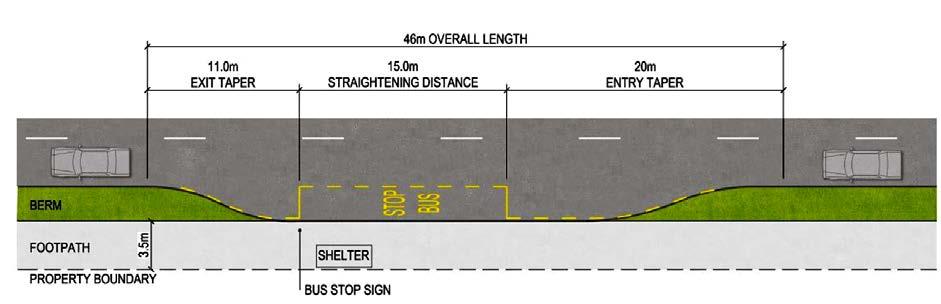
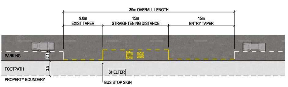
INTER – CITY BUS TERMINAL AT BANEPA Aakash Bhochhibhoya 16
Figure 2-2 : Diagram of a Kerbside bus stop with parking either side for a single ‘standard’ 13.5m long tag axle bus
Figure 2-3 : Diagram of a fully indented bus bay for a single ‘standard’ 13.5m long tag axle bus
2.1.3. LOCAL BUS TERMINAL
Bus services at a local bus terminal cater to routes whose starting and terminating points connect two different places in the same city. On these routes, buses stop to board and offload passengers at short intervals, usually about 0.5 km.
2.1.4. INTER-CITY BUS TERMINAL AND INTER-STATE BUS TERMINAL (ISBT)
An intercity bus service (North American English) or intercity coach service (British English and Commonwealth English), also called a long-distance, express, over-theroad, commercial, long-haul, or highway bus or coach service, is a public transport service using coaches to carry passengers significant distances between different cities, towns, or other populated areas. Unlike a transit bus service, which has frequent stops throughout a city or town, an intercity bus service generally has a single stop at one location in or near a city, and travels long distances without stopping at all. Intercity bus services may be operated by government agencies or private industry, for profit and not for profit 9 Intercity coach travel can serve areas or countries with no train services, or may be set up to compete with trains by providing a more flexible or cheaper alternative. (Garber, 2015)
Starting and terminating points connect two different states, regions/districts, or cities; long intervals between stops, usually greater than 10 km.
INTER – CITY BUS TERMINAL AT BANEPA Aakash Bhochhibhoya 17
Figure 2-5 : Inter-city bus terminal and inter-state bus terminal (ISBT)
9 Traffic and Highway Engineering By Nicholas J. Garber, Lester A. Hoel, page 46
Figure 2-4 : Local bus terminal
2.2. SUSTAINABILITY
The word 'sustainability' is derived from the Latin ''sustinere'' (tenere: to hold; sus: up). Dictionaries provide more than ten meanings for sustain, the main ones being to “maintain", "support", or "endure”. 10
The concept of sustainability has in recent times been introduced to combine the concern for the welfare of the planet with continued growth and human development. It is a widely-used term meaning all things to all people with the most prevalent definition put forward by the World Commission on Environment and Development (the Brundtland Commission of the United Nations) in 1987. This defined sustainability development as ''development that meets the needs of the present without compromising the ability of future generations to meet their own needs” (McDonough, 2000, pg 4). In order to further embrace the idea of a global ecology with intrinsic value, the definition was expanded to include the reconciliation of environment, social equity and economic demands - the so called ‘three pillars’ of sustainability (UNGA, 2005). This concept of sustainable development drove a program of development presented by the United Nations Environment Program UNEP in the seventies alongside the concept of eco-development (UNCED, 1992). Global interest reached its peak with the adoption of the environmental concept of sustainable development on a global scale at the Earth Summit that was held in Rio de Janeiro in 1992. The World Conference for Social Development followed in 1995 adopting the concepts of sustainability and sustainable development. These were followed by the World Conference on Sustainable Development in 2002. Later on, the World Summit in 2005 sought to investigate the sustainability dimensions as represented in environmental, social and economic demands. Planning for sustainability requires all of this as well as a more comprehensive approach with the integration of a wide range of actors and stakeholders representing different societal sectors, providing the knowledge base for sustainable development processes and enabling decision-makers in cities to make better-informed decisions (Baker, 2006). The relationship between urban design and sustainability is examined later on in this chapter.
2.3. URBAN DESIGN
Webber (2008, p. 1) defines urban design as "the process of molding the form of the city through time". Previously, Tirikatene (2007, p. 6) defined "urban design as the multi-discipline of designing and organizing all the physical elements that constitute cities to create harmonious and successful places for communities". Urban design can be said, therefore, to include the design, organization and arrangement of buildings, surrounding environment, transport systems and effective infrastructure. In addition, it is a framework that organizes a set of the key elements into a network 10 Charles, T. (1964): The Shorter Oxford English Dictionary. Oxford: Clarendon Press
INTER – CITY BUS TERMINAL AT BANEPA Aakash Bhochhibhoya 18
of squares and streets (Childs, (2010)). Lawson (2006) stated that urban design is about shaping the form of the physical urban fabric, by organizing urban structure, manipulating relationships between elements, creating coherent ensembles of buildings and spaces. Therefore, urban design in the specific sense, grew out of an effort to combine art and science in the three-dimensional planning of urban environments (Mumford, 1937– 1969). Wall and Waterman (2009, p. 17) argue that "urban design is a place making process which consists of three dimensions for the urban forms and surrounding spaces." Moreover, urban design can operate on a variety of scales, although it tends to be most associated with the scale greater than, or equal to, architecture (buildings) and less than equal to that of town planning (settlements) (Marshall and Caliskan, 2011).In discussing and exploring key aspects related to sustainable urban design, such as; principles, indicators, challenges and solutions, there should be the examination of the relationship between urban design and sustainability.
2.4. RELATIONSHIP BETWEEN URBAN DESIGN AND SUSTAINABILITY
Purayil (2004, P.20) argues that urban design for sustainability supports the concept of combining economic development with environmental progress. 11 Mougthin and Shirley (2005) have also strongly argued that sustainable development and urban design are indeed linked. Abdulgader and Aina (2005) too state that urban design gives the opportunity to guide city development towards sustainability. Miller (2002) previously noted that most city areas use urban design and design coding to determine present and future use of each parcel of land in the area. 12 A clear thread in the literature supports this position starting with Kostof (1991) who argues that the relationship between sustainability and urban design was important.
Boyko et al. (2005, p.1) note that "examination of this relationship highlights the need to understand those who are the decision makers and what influences their decisions”. Others have called for a clear awareness of the role that decision-makers play in the local and national governance order to stress the importance of sustainability in urban design (Kagiolou, et al., 1998). On another level, there is a need for local and national governments to continue to stimulate the key decision makers and stakeholders to become more responsible about understanding how the urban design process works (Boyko, et al., 2005). This gives those involved in the urban design process more information to create urban environments and to contribute to the design and operation of sustainable urban environments. Tirikatene (2007, p.9) stresses the importance of this saying that "sustainability is an
11 Purayil, V. (2004): Sustainable urban design in a developing city a critical analysis of Calicut, India. Institute of Technol ogy. Submitted at the National University of Singapore, Singapore. April 2009
12 Miller, R., and Floricel, S. (2000): Transformations in arrangements for shaping and delivering engineering projects. In R Miller and DR Lessard (Eds.), the strategic management of large engineering projects: Shaping institutions, risks, and governance. Cambridge: The MIT Press, pp. 51-74.
INTER – CITY BUS TERMINAL AT BANEPA Aakash Bhochhibhoya 19
over-arching concept incorporating economic prosperity, resilient communities, civic and social leadership, environmental stewardship, social cohesion and cultural diversity, now and into the future".
It is necessary to examine the relationship between urban design and sustainability in order to further appreciate and understand sustainable urban design (Miller, 2002). This will be effectively achieved in this thesis through the discussion of the key aspects, related to sustainable urban design, such as: principles, indicators, challenges and solutions. This is in order to formulate strategies for the application of the principles of sustainable urban design within cities (European Union Experts Group on the Urban Environment (EUEGUE), 2004; 1995).
2.5. SUSTAINABLE URBAN DESIGN
Thomas and Fordham (2003, p. 3) describe sustainable urban design as "the sustainability in the physical aspects of an urban environment that include the buildings and their engineering systems, transport systems, green and open spaces, energy, water and waste systems". It can also incorporate architecture, urban planning, landscape architecture, and civil engineering (Neuman, 2005). Farr (2007) defines sustainable urban design as walk able and transit-served urbanism integrated with high performance of both buildings and infrastructure. Sustainable urban design has also been described as the act of unifying architecture, city planning, and environmental design for progressing towards a better life (Adhya et al., 2010). McGeough et al. (2004, p. 5) define sustainable urban design as "the state a metropolitan community reaches once it is able to meet the needs of the present generation without compromising the ability of future generations to meet their own needs". This definition first appeared in 1987 when the United Nation’s World Commission on Environment and Development published the common future report (WCED, 1987).
McGeough et al. (2004) emphasize that sustainable urban design does not exclude the economic growth, environmental preservation and social development objectives but that it fundamentally supports these objectives (EUEGUE, 2004).
INTER – CITY BUS TERMINAL AT BANEPA Aakash Bhochhibhoya 20
Figure 2-6 : Sustainable urban design
2.6. SUSTAINABLE URBAN DEVELOPMENT
Sustainable development has been defined as development that meets the needs of the present without compromising the ability of future generations to meet their own needs. However, sustainable urban development implies a process by which sustainability can be attained, emphasizing improvement, progress and positive change, incorporating both environmental and social dimensions.
It is a dynamic process geared towards achieving suitable conditions that address environmental, economic, social, and governance sustainability concerns. (Rasoonlimanesh et al., 2011)
Urban performance currently depends not only on the city's endowment of hard infrastructure but also, and increasingly so, on the availability and quality of knowledge communication and social infrastructure. A city can be defined as ‘smart’ when investments in human and social capital and traditional (transport) and modern (ICT) communication infrastructure fuel sustainable economic development and a high quality of life, with a wise management of natural resources, through participatory action and engagement. A smart city has:
a smart economy
smart mobility
a smart environment
smart people
smart living
smart governance
On the other hand, a sustainable development means a city or town will be sustainable in terms of transportation, energy consumption, public health etc.
Refer annex 8.2, for diagram that describes bus terminal's role in sustainable urban design.
To identify a development as sustainable, one has to ask, will the development:
Prioritize public transport, cycling and walking, and dissuade the use of cars?
Ensure accessibility for everyone, including people with disabilities?
Encourage more efficient use of energy and a reduction in greenhouse gas emissions?
Include the right quality and quantity of public open space
Include measures to ensure satisfactory standards of personal safety and traffic safety within the neighborhood?
Present an attractive and well-maintained appearance?
Promote social integration and provide for a diverse range of household types, age groups and mix of housing tenures?
Protect, and where possible enhance, the built and natural heritage?
Provide for Sustainable Drainage Systems? (Hoque, February 2016)
INTER – CITY BUS TERMINAL AT BANEPA Aakash Bhochhibhoya 21
2.6.1. BUS TERMINAL’S ROLE IN SUSTAINABLE URBAN DESIGN
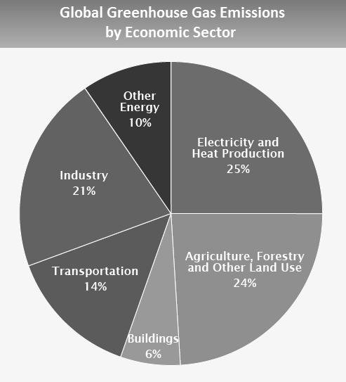
2.6.1.1. GLOBAL EMISSIONS IN WORLD
Source: (IPCC, 2014)
2.6.1.2. IN CONTEXT OF NEPAL
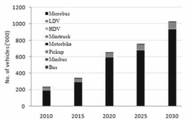
The road vehicles are considered one of the main sources of urban air pollution and the consumer of fossil fuel energy in a large number of cities, particularly in the developing countries of Asia. The Kathmandu valley, the home of 2.5 million people (The World Bank, 2014), is one of the fastest growing metropolitan. The transportation sector is the largest source of air pollution in the valley.
Source: (The World Bank, 2014)
INTER – CITY BUS TERMINAL AT BANEPA Aakash Bhochhibhoya 22
Figure 2-7 : Global greenhouse gas emissions by economic sector (2014)
Figure 2-8 : Evolution of surviving vehicle fleet (‘000) in the Kathmandu valley
2.6.1.3. NEED OF SUSTAINABLE URBAN DEVELOPMENT
If the above listed questions are answered by the bus terminal building and the site then, it will play a major role in sustainable urban development. Whereas, well designed bus terminal will also prioritizes public transport rather than private owned vehicles; which increases the traffic congestion and toxic gas emissions.
Throughout the world, new growing cities are planning to achieve a sustainable urban development. Putrajaya, Cyberjaya of Malaysia; Chandigarh, Ahmedabad of India are some of the examples of sustainable cities.
Therefore, the bus terminal should include the following so that to achieve the sustainable urban development:
Land-use priorities should be revised for compact, diverse, green, safe, pleasant and mixed-use communities near transit modes and other transportation facilities Transportation priorities should be revised for green transport Renewable source of energy should be used in transportation like (electric trolley bus, trams, etc.). Better facilities should be provided in public transport Universal design (designing also for people with disabilities) should be applied. Bus terminal should be designed as one of the public open space in a community. Personal safety and traffic safety are the priority while designing. Well-maintained appearance and cleanliness are necessary to achieve in good psychological mood of both passenger and drivers. Designers should enhance the green spaces and also the respect the heritage site to achieve a sustainable urban development.
INTER – CITY BUS TERMINAL AT BANEPA Aakash Bhochhibhoya 23
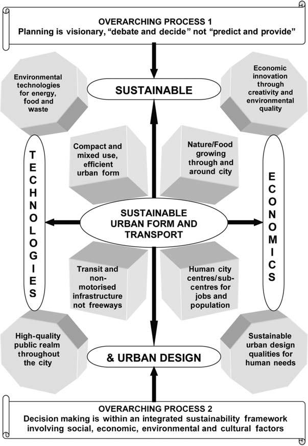
Figure 2-9 : Sustainable urban form and transport
2.7. HISTORY
2.7.1. HISTORY (WORLD)
The first ever recorded bus stop was in bishops stortford and was believed to be constructed in 1890, this linked bishops stortford to the town of Colchester.
2.7.2. HISTORY (NEPAL)
Ratna Park was the first terminal of the valley. The long route buses also operated from here. Due to the congestion created due to the inter city and intra city vehicles, the long route vehicle terminal operating in the western highway was shifted to Gongabu in 1993 A.D. this helped in decreasing the urban sprawl of the valley as it lies at the ring road and is near to Kalanki which is the main transit corridor linking the city to the major parts of the country.
Gongabu Bus Park is the only bus terminal regulating the inter-city transport services in the western corridor of the valley. Kalanki being more accessible than Gongabu has been developed as the bus stop for the long route vehicles. This has affected the traffic system of the whole valley as KalankiThankot, Kalanki- Ratnapark, Kalanki- Balkhu are busier roads. Due to the passenger preference at Kalanki inter- city microbus facilities are being operated at Kalanki with no terminal facilities.
2.8. FUNDAMENTAL PHIOSOPHICAL ISSUES
Congestion through outsized zoning and providing insufficient long- and short-range parking.
Bus terminal and its architectural expression
Socioeconomic aspects of a bus terminal
Employment opportunities through its services and construction.
Locational attributes
An essential component of urban transport facilities which defines the beginning (origin) or end (terminating) of the line for the transportation system which also facilitate or act as an interchange before, during or after the road haul movement including servicing facilities for vehicle.
Terminals are needed where number of services terminates or where there is an exchange of passengers from one service to other. When the scale of operation is high and the interchange between various services and modes become predominant, the exchange terminal is necessary to facilitate the operational requirements.
Points to be considered while designing a bus terminal are:
To achieve an efficient, free and rapid flow of traffic
To minimize traffic accidents
INTER – CITY BUS TERMINAL AT BANEPA Aakash Bhochhibhoya 24
To control the haphazard urban growth
To control environmental problems
Some other design considerations are:
Accessing bus transit facilities:
Disabilities act: the design of transit facilities needs to consider all possible disabled users, including: wheelchair-aided; cane-, crutch-, and walker-aided; and visually-, hearing-, and cognitively-impaired people. Accessible features in a facility must take into account the reach ranges of a person in a wheelchair, the sight and hearing abilities, and they should be easily operable. In addition, all signage, signals, markings or traffic control devices installed on, over, or adjacent to a street, highway, pedestrian facility, or bikeway by a public agency must be regulated and adopted by every state.
Pedestrian-oriented consideration: to make a walk able environment and responsive to the needs of riders of various disabilities and ages, and promote safe street crossing.
Bus passenger facilities
Security and crime prevention
Parking and auto relationship to transit demand
Green design consideration: Eco friendly construction, or ―green‖ building and design considerations aims to conserve natural resources and improve environmental quality throughout a buildings life-cycle via the application of principles, techniques and materials.
Spaces, functions and energy studies needed to be studied in details are as follows:
Circulation and parking pattern of vehicle.
Passengers flow pattern and their needs.
Functional elements and planning criteria
Architectural character
Energy and environmental considerations
2.9. PLANNING CRITERIA
In general, the four basic planning criteria for planning of terminals are –
Need Size
Location Design
INTER – CITY BUS TERMINAL AT BANEPA Aakash Bhochhibhoya 25
2.9.1. NEED
Need of the terminal arises with increase in the demand. An organized bus terminal should meet the following requirements-
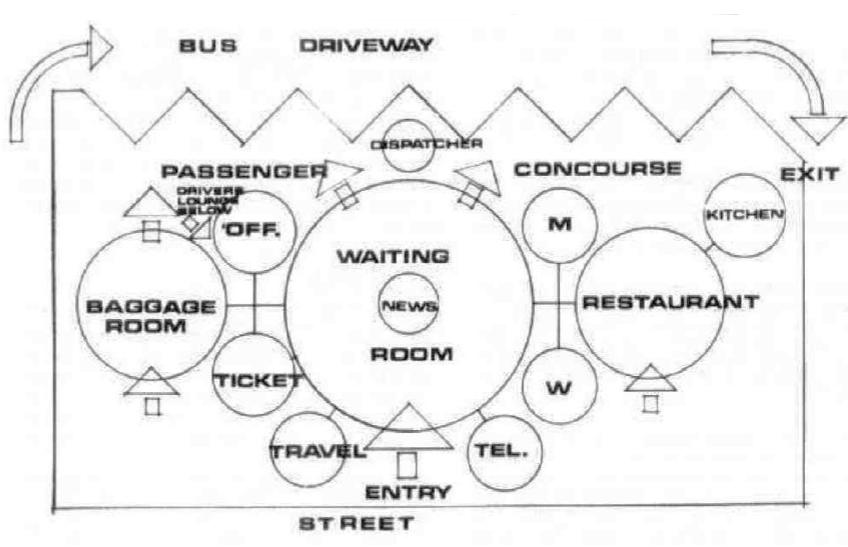
2.9.1.1. ACCESSIBILITY
Accessibility and mobility are about much more than just providing wheelchair ramps. Making a neighborhood accessible, with a fully integrated and accessible transit system, means that right from the start, you need to focus on the mobility-impaired. Everyone, from senior citizens to young children, from the disabled to the able-bodied, should be able to move about safely and without any restrictions. Prominent signage and proper design are needed to ensure that people can easily locate transit facilities, that the facilities are safe, and that people can get on and off buses quickly and easily. This is not difficult, but it does require planning and forethought. All images in this section show the basic requirements for accessible design.
INTER – CITY BUS TERMINAL AT BANEPA Aakash Bhochhibhoya 26
Figure 2-10 : General flow in a bus terminal
Pedestrians: The most important and most vulnerable users should be afforded the best access to the interchange and given priority at all crossing points.
Bicycles: Giving priority to this mode recognizes both the desirability to increase usage of this mode and the vulnerability of the mode.
Buses: The need for reliability and the concentrated usage (by customers) of this mode means there is a need to give priority to buses.

Kiss and Ride: Optimum function of this mode requires close access to interchange entrance/s. This mode includes taxi stands.

Park and Ride: Whilst an important part of many interchanges, it is the access mode that should least affect the others.

It is very important to recognize the different requirements and mobility levels of individual passengers when providing public transport infrastructure and facilities. New Zealand is a signatory of the United Nations Convention on the Rights of Persons with Disabilities, and as such there are expectations that public transport infrastructure and facilities should be accessible to all, regardless of ability, age, gender or race. Accessibility improvements to infrastructure will benefit all users. A key measure of public transport accessibility is that the vehicle aligns close and parallel with the stop platform. However, a broader view of accessibility includes ease to use infrastructure, good urban coverage, customer orientated and accessible by a variety of modes.
2.9.1.2. COMFORT AND CONVENIENCE

Thermal comfort
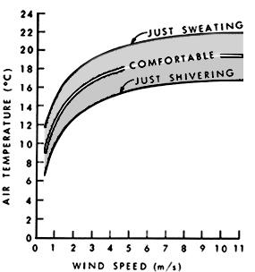


Acoustic comfort
Wind protection
Visual comfort
Provision of public transport infrastructure and facilities should enable operational efficiency for the public transport network. This efficiency should include the movement of vehicles, loading of vehicles and consideration of design and location of the non-public
INTER – CITY BUS TERMINAL AT BANEPA Aakash Bhochhibhoya 27
Figure 2-11 : Access hierarchy
infrastructure (driver’s facilities, depots etc.). Improved overall operational efficiency requires all the modes and services to operate as one network.
All public transport infrastructure and facilities should be provided at a cost that is considered affordable. The costs associated with a specific piece of infrastructure or facility should be outweighed by the benefits. It should be strongly recognized in any benefit/cost assessment that improved public transport infrastructure and facilities will unlock economic, social and environmental benefits.
2.9.1.3. SAFETY
Infrastructure and facilities provided as part of the public transport network should be safe. Safety includes safely accessing the network, safety while waiting at bus stops/stations and providing infrastructure that is safe to use. All infrastructure and facilities provided as part of the public transport network should promote safety and a high level of personal security. The perception of safety will have an influence on the use of the public transport network. The relative safety of using public transport extends to the broader infrastructure and facilities supporting the network, including depots and other non-public areas.
In a survey of bus riders and confirmed by many other studies, safety is consistently ranked as one of the highest priorities at a bus stop (Taylor et al., 2007). It is understandable that personal safety is the basis upon which all other improvements can be made. Without an adequate level of perceived safety, commuters will simply choose not to use the bus stop (Nabors et al., 2007). Issues of safety may result from criminal activity or physical hazards, such as high vehicular traffic or slippery surfaces. It is important to note the differences between perceived risk and actual risk, which may be correlated or inversely correlated depending on the type of risk (Cho, Rodríguez, & Khattak, 2009).
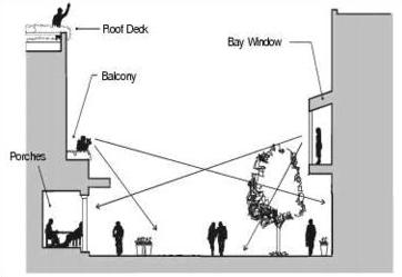
Risk of accident
Risk of crime

INTER – CITY BUS TERMINAL AT BANEPA Aakash Bhochhibhoya 28
photo: SEATAC Municipal Code
Figure 2-12 : Natural surveillance reduces opportunities for crime without target hardening
2.9.1.4. EASY PROCESSING
There are many urban realm factors that affect bus ridership; many of which relate to the trip that connects one’s home to the bus stop, which is often by walking or cycling. Studies have shown that greatest predictor of transit use is proximity (Cervero, 2002; Gutiérrez & García-Palomares, 2008).
The closer one lives to a transit stop, the more likely one will take transit (Hoehner, Brennan Ramirez, Elliott, Handy, & Brownson, 2005). The typical catchment for a bus stop is contained within a 400 meter radius around the stop and can be larger for faster forms of transit (Gutiérrez, Cardozo, & García-Palomares, 2011).
Bus bays are located at bus terminal. The location of bus terminal are determined by bus passenger demand and a need to minimize access time and maximize a potential catchment area. They are normally located 700m apart in urban areas. In rural areas a longer spacing may be acceptable. Refer annex 8.3, for easy bus processing in entry, parking and riding back, and turning radius.
2.9.2. SIZE
Operational parameters: Planning and designing of bus terminals is significantly influenced by the terminal’s operational attributes. Several operational parameters bear upon a bus terminal’s requirements. These include the number of routes served and their peak frequency, volume of waiting passengers, spaces for bus stacking (idle parking), the mix of terminating and passing services, and passenger circulation (Trans Link Transit Authority 2011). Thus, it is essential to the terminal planning and development process that the operational parameters are fully understood and ac-counted for.
Existing capacity and future demand estimation: In addition to operational requirements, terminal planning and designing should also factor in the estimates for existing capacity and future (horizon year) demand. The considerations for redressal of potential short-term and long-term capacity constraints, and future expansion on the basis of estimated horizon year demand should be incorporated early in the planning stage (Trans Link Transit Authority 2011).
Terminal Size: This characteristic denotes the scale of a bus terminal, irrespective of its hierarchy (interstate or local). Terminals are categorized under three scales based on the bus flow per hourLarge (more than 300 buses per hour), Medium (more than 60 up to 300) and Small (less than or equal to 60).
Terminal Operations: This characteristic determines the operations type of a bus terminal, in terms of allocating boarding bays to different routes. The categorization is based on the current preference and norms followed by the terminal operator (usually state or city transport undertakings). In India, two operations types are observed:
Fixed Route Bay Allocation- This operations type is usually observed in medium and large bus terminals, and entails fixed (specific to a route) bay allocations i.e. a particular route
INTER – CITY BUS TERMINAL AT BANEPA Aakash Bhochhibhoya 29
will be allotted its specific bay or a boarding spot, and every bus plying on that route will always commence from there. More than one route may be assigned to the same bay.
Dynamic Bay Allocation- In this type of operations, buses dock at a vacant bay or one assigned by the terminal supervisor at entry. These are not fixed to a particular route. Such terminal operations are observed mainly at small terminals; they can work with large bus flows only in the presence of a good passenger information system (PIS).
The following factors are considered to characterize the size of the terminal and its functions-
2.9.2.1. FLOW OF TRAFFIC
2.9.2.2. SYSTEM CHARACTERISTICS
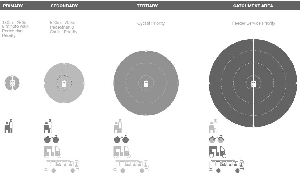
2.9.2.3. USER CHARACTERISTICS
The land requirement for a bus terminus or public transport interchange is determined by several factors which include the number of routes served and their peak frequency, volume of waiting passengers, spaces for bus stacking during off-peak/meal break periods, the mix of terminating and passing services, overtaking and internal vehicle and passenger circulation.
Minibus termini should preferably be located off-street in close proximity to existing or future centers of demand. If possible, they should be incorporated into public transport interchanges. On average a 3-bay terminus with each bay accommodating 3 vehicles should be adequate. The minimum land requirement is about 800m2.
2.9.3. LOCATION
Locational characteristics make for the key factor attracting passengers using the bus terminal (Trans Link Transit Authority 2011). Centrally located (core city areas) bus terminals are desirable for operational efficiency and passenger convenience, as they provide ample interchange
INTER – CITY BUS TERMINAL AT BANEPA Aakash Bhochhibhoya 30
Figure 2-13 : Station area influence zones Source: EMBARQ India
opportunities. Addition-ally, they are potential candidates for using terminals as a vibrant city space Peripheral terminals, when integrated with depot functions, work best in minimizing dead mileage.
The selection of the location should satisfy the following criteria-
2.9.3.1.
IT SHOULD FORM A COMPONENT IN THE HIERARCHY OF TRANSPORT SYSTEMS
Bus depots should be on level terrain with suitable vehicular access to the road system and centrally located in relation to bus terminal facilities to enable dead mileage to be minimized.
2.9.3.2. IT SHOULD BE IN A LOCATION THAT MINIMIZES THE IMPACTS
Bus terminal facilities may be located in multi-storey developments, preferably on the ground floor. As they have potential to cause air pollution and noise impacts on nearby sensitive uses, they should be so sited or designed as to minimize such impacts.
The siting of bus depots should take into account the environmental intrusion due to 24-hour operation of maintenance and repair activity and noise nuisance caused by buses travelling to and from the bus depot at late night and early morning
2.9.3.3. THE CONCENTRATION AND DISPERSAL COSTS SHOULD BE MINIMUM
Bus terminal facilities should be centrally located so as to be conveniently accessible on foot to residential, commercial and industrial activities. Access to the existing and proposed road system should be convenient and the ingress and egress points so located as not to cause conflict with traffic circulation on the adjacent road system and to facilitate satisfactory internal circulation. Where they form part of a public transport interchange, access would be physically separated but walking distances between modes should be minimal.
2.9.3.4. IT SHOULD BE LOCATED SUCH THAT AS POINT OF COORDINATION AND INTEGRATION BETWEEN INTER-CITY AND INTRA-CITY TRANSPORT
Service terminal points are usually provided where 1 or 2 bus routes are terminated and where the number of departure bays is unlikely to exceed four. A regulator's kiosk will be required at such terminal point.
Bus termini are usually provided in large residential developments and in localized commercial or industrial areas. Normally, a minimum of 4 departure bays are provided for operation of services and stacking of buses during off-peak/meal break periods. One of these bays should be sufficiently wide to permit overtaking a stationary vehicle. A regulator's kiosk and the other ancillary provisions would be required.
If bus-bus interchange is to be pursued at the bus termini, additional bays would be needed.
INTER – CITY BUS TERMINAL AT BANEPA Aakash Bhochhibhoya 31
2.9.4. DESIGN
Following points should be kept in mind for efficient workability of terminal-
Source: (Zhang, 2012)
The Bus Stop Urban Design Techniques are a set of parameters for the design of many aspects of a bus stop in hope of achieving the goals set out in the previous section. Each goal is supplemented with research and precedents. The 9 techniques address:
Lighting: Even, white light with minimal shadows provides the best environment for activities and enhances safety. Pedestrian scale lighting adds to the character of the location.
Seating: Adequate seating with a variety of microclimatic conditions is important for comfort and allows riders to adapt to their preferences. Special paving can denote pedestrian priority.
Cover: Cover provides primary weather protection from precipitation and excessive solar exposure. Where possible, cover may be achieved by adjacent awnings or vegetation.
Amenities: Amenities such as public art, drinking fountains, and waste bins not only improve the experience of the bus user, but they also benefit the immediate neighborhood.
Information: Transit information provided at a stop can greatly reduce rider anxiety in waiting. Extra space may be dedicated to displaying community information if the stop is in a high traffic area.
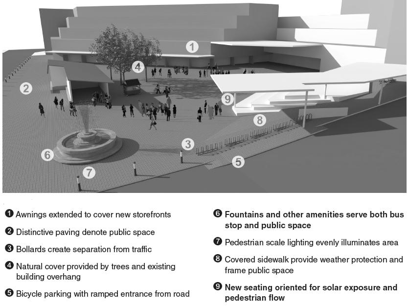
INTER – CITY BUS TERMINAL AT BANEPA Aakash Bhochhibhoya 32
Figure 2-14 : Design perspective of bus terminal building and its surrounding
Vegetation: Vegetation can manage the microclimate of a stop by providing shade, cover, and wind blocks. It can also be used to enhance the aesthetics of the location.
Traffic management: Traffic management techniques focus on reducing vehicular speeds around bus stops and making biking and walking in the area safer and more pleasant.
Pedestrian infrastructure: The pedestrian network around a stop is an extension of the transit line. Therefore, it is important to have high quality walking environments to attract new riders.
Bicycle infrastructure: Many residents would bike to bus stops if it were more convenient. To encourage such behavior, adequate bike paths and bike parking must be provided.
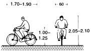
2.9.4.1. SEGREGATION OF BUS AND NON-BUS TRAFFIC
2.9.4.2. SEGREGATION OF PEDESTRIAN AND VEHICULAR MOVEMENT
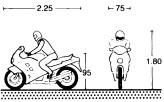
2.9.4.3. ELIMINATION OF VEHICULAR TRAFFIC CONFLICT
2.9.4.4. SEGREGATION OF PEDESTRIAN FLOWS
2.9.4.5. MINIMUM PROCESSING FOR THE BUSES
2.9.4.6. SEGREGATION OF TRANSPORTATION AND NO-TRANSPORTATION ACTIVITIES
Bus bays are provided to enable buses to stop for boarding/alighting passengers without obstructing other traffic.
The provision of bus bays should be considered on rural roads, feeder roads, primary distributor roads and 2-lane, 2-directional single carriageway district and local distributor roads. Where bus bays are required, the carriageway width in Annex 8.4; table of minimum carriageway widths in urban and rural areas, should be increased by 3.25m. The length of bay for operation of one bus route would normally be 40m.
2.10. CIRCULATION AND PARKING PATTERN OF VEHICLE
2.10.1. VEHICULAR STANDARDS
INTER – CITY BUS TERMINAL AT BANEPA Aakash Bhochhibhoya 33
Figure 2-16 : Bicycle
Figure 2-15 : Motorcycle
2.11. BUS BERTHS
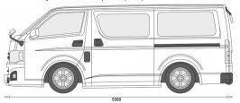
A critical component at major bus terminals is the provision of bus transfer areas where buses serving the station can board and alight passengers. For larger bus terminals, numerous berths and more sophisticated designs are applied. There are typically 4 types of bus berths which are integrated into terminal design which are as follows.
1. Linear (Curb side) Berth:
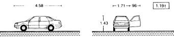
These bays can operate in series and have capacity characteristics similar to on-street bus stops.
2. Saw tooth Berth:
This loading configuration is popular in urban transit centers, and designed to permit independent movements into and out of each bay. Saw tooth may be straight saw tooth or radial saw tooth
3. Angle:
This loading type is limited to one bus per bay, and requires buses to back out. This is often used for inter-city coach terminals, with long dwell times, single-door entry, and luggage loading requirements.
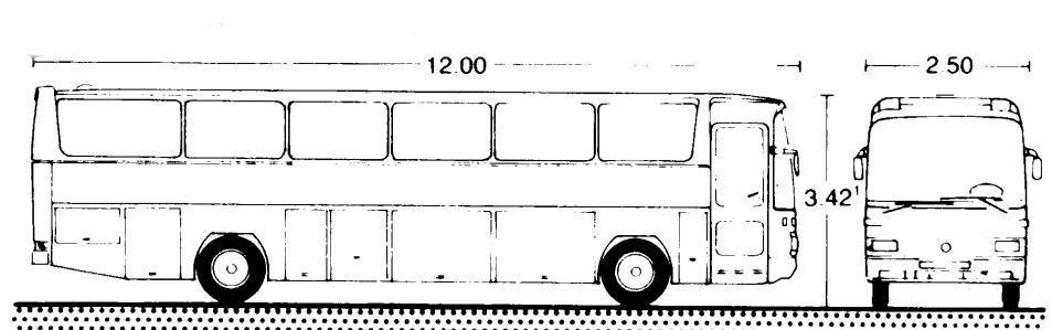
4. Drive Through:
Drive-through angle bays do not require buses to back out of the bay and may accommodate multiple vehicles.
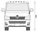
INTER – CITY BUS TERMINAL AT BANEPA Aakash Bhochhibhoya 34
Figure 2-18 : Car
Figure 2-17 : Micro bus
Figure 2-19 : Bus
2.12. RAMPING
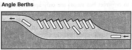
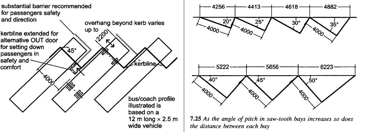
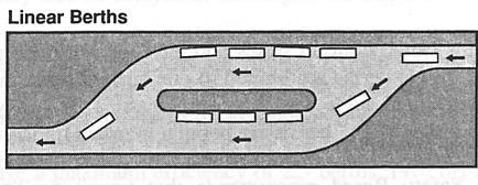
Where roadway ramping down or up, at entrances or exits to runways is necessary, care should be taken to avoid sharp grade changes which will result in discomfort to passengers or rough treatment of equipment, particularly when heavily loaded.
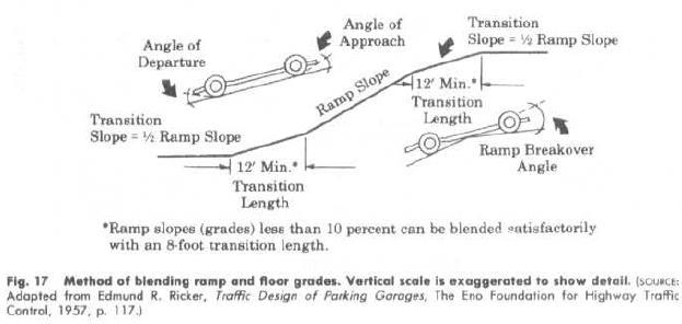
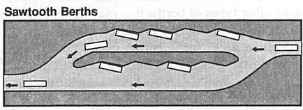
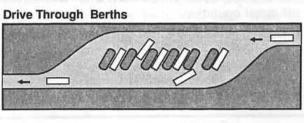
INTER – CITY BUS TERMINAL AT BANEPA Aakash Bhochhibhoya 35
Figure 2-20 : Types of Berth Loading
Figure 2-21 : Saw tooth loading
..
Figure 2-22 : Ramping
2.13. TURNING RADIUS FOR DIFFERENT TURNING SITUATIONS
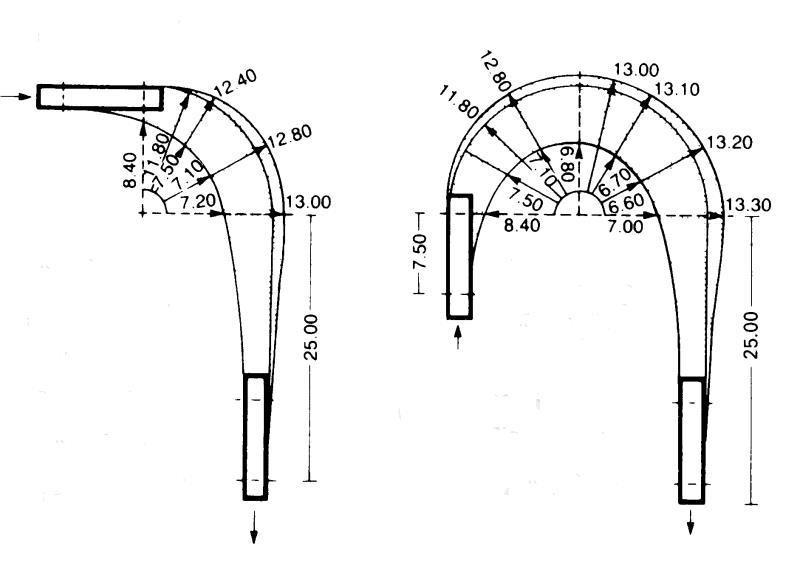
2.14. POSITIONING OF BUS TERMINAL BUILDING IN RELATION TO BUS TURNING LOOP
2.15.
PASSENGERS FLOW PATTERN AND THEIR NEEDS
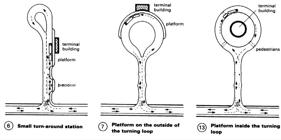
2.15.1. OBJECTIVES
• Organization: The purpose of the Terminal is the movement of people. Terminals should be planned with clarity of organization for the individual passenger spaces. The sequence of spaces and the architectural treatment of spaces should be designed with a simplicity that reinforces the recognition of pathways, destinations, and functions in the terminals.
INTER – CITY BUS TERMINAL AT BANEPA Aakash Bhochhibhoya 36
Figure 2-23 : Turning radius for different turning situations
Figure 2-24 : Bus terminal building in relation to bus turning loop
• Character: Architectural factors such as volume, hierarchy, proportion, sequence, color, materials, lighting, and contrast should all be used in the Terminal designs. The designs will not be considered sufficient if they do not use such factors to create a special environment.
• Planning of Space: There are eight main aims in the planning of space in the terminals:
Avoidance of congestion
Resilience to surges in demand or ferry disruption
Capacity for evacuation
Links to transit transfer points
Clarity of pathway and destination
Architectural statement of civic purpose
Hierarchy of function in spatial relationships
Ability to accommodate future increases in passengers and facilities
2.16. PASSENGER CIRCULATION
2.16.1. CIRCULATION PLANNING
• The objective of the circulation system is to provide the capacity to clear the float before the arrival of the next vessel, during normal peak operations.
• A pedestrian flow diagram based on normal peak conditions shall be developed to confirm directional flows and capacities of all circulation elements. The diagram shall be adequate to accommodate the peak conditions without waiting time at any circulation element. Since the diagram is directed toward normal operations, not emergency egress, a distribution factor does not have to be applied to the ridership forecasts during the peak hour.
• Benches and floor-mounted signs shall be kept clear of primary circulation routes.
• Backtracking shall be avoided and pedestrian cross flow throughout the terminal shall be maintained in a simple circulation pattern that minimizes the distance between terminal elements. Signage, visual, and tactile cues shall be incorporated.
• Surge spaces are required where passengers change from one mode of circulation to another, or pass through obstacles, such as gates or doors
• An information and guidance system shall be provided with an emphasis on clarity for the needs of first time users and passengers with special needs.
2.16.2. CIRCULATION STANDARDS
The way people move around a building will affect how much they interact. Small seating areas along circulation routes, attractive lighting and color and views out can all encourage casual interaction. Circulation may be of two types: horizontal and vertical circulation. The width of the horizontal circulation is:
INTER – CITY BUS TERMINAL AT BANEPA Aakash Bhochhibhoya 37
• Primary circulation, min, 1.5m
• Secondary circulation, min, 0.9-1.5m
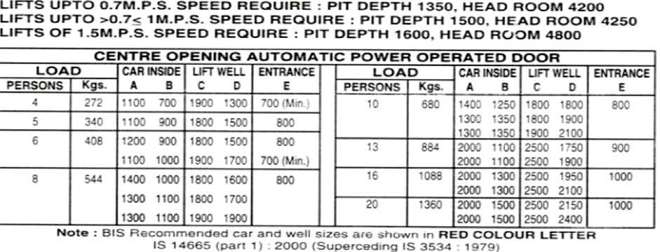
• Tertiary circulation, min, 0.9m
The vertical circulation may consist of staircase, lift and escalators.
2.16.2.1. STAIRCASE
The width of the staircase should be provided such that one should pass easily without dashing to other person as shown in the fig.
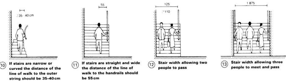
2.16.2.2. LIFTS
The positioning of lifts and lift lobbies and their no. and speed can be critical to how staff and visitors perceive the building. Lift should move a minimum of 15% of the building‘s population within 5 minutes, with a maximum weight of 30 seconds and an actual car capacity of 80%.
• For preliminary assumption, the number of elevators required may be estimated on the basis of one elevator per 2300 m2 of rentable area.
• Lift lobbies should be 1.8-2.75 m if lift is on one side only.
• 3-3.75m if lifts are on both sides.
INTER – CITY BUS TERMINAL AT BANEPA Aakash Bhochhibhoya 38
Figure 2-25 : Staircase width
Figure 2-26 : General specification for selection of lift
2.16.2.3. ESCALATORS
Escalators can carry large no. of people quickly, but they are expensive in terms of both money and space. They are not designated as stairs in the provision of emergency escape. Escalators rise at an angle of between 30° and 35°. Escalators length is calculated as follows:
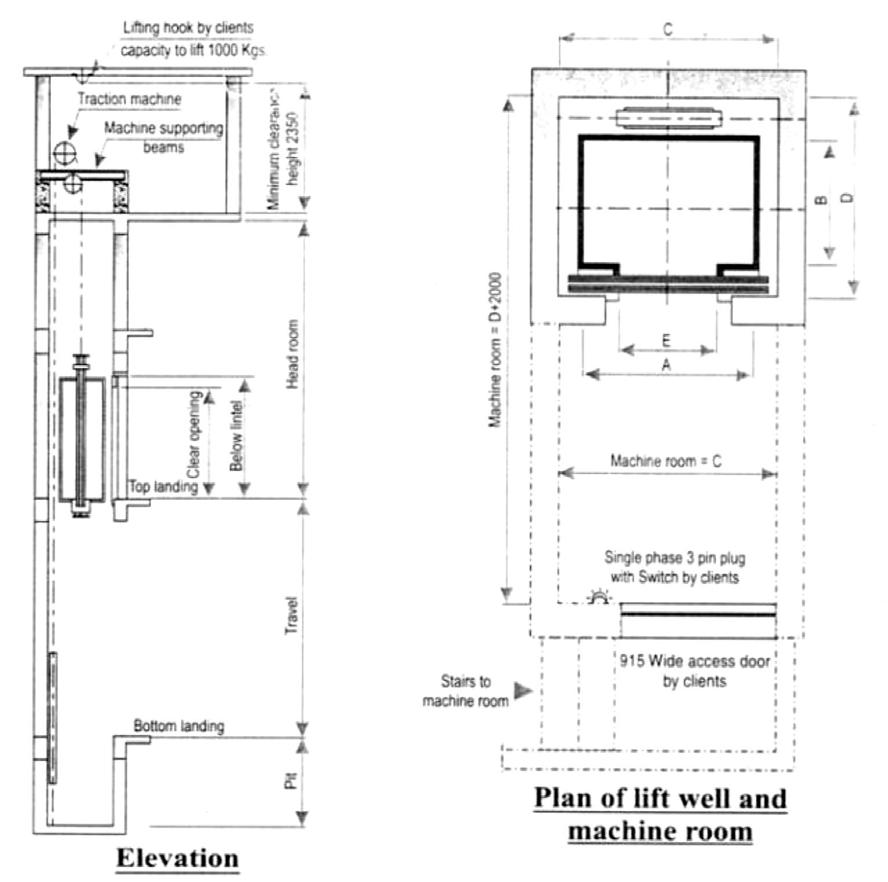
Length in plan
• With 300escalator= 1.732 x storey height
• With 350 escalator= 1.428 x storey height
INTER – CITY BUS TERMINAL AT BANEPA Aakash Bhochhibhoya 39
Figure 2-27 : Elevator details
2.16.3. PLANNING FOR SAFETY AND SECURITY
• The design of the terminal exit capacities and times for evacuation shall be in accordance with mass carrying capacity of building in those cases where there are conflicts between the fire separations required by State and local Building Codes. These analyses shall be complementary and used to form practical and suitable safety policies with Building officials.
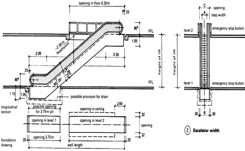
• The Terminals shall comply with the Building Codes of the jurisdictions in which the stations are located.
• All Terminal entrances must be lockable from inside and outside.
2.16.4. PASSENGER CIRCULATION & ACCESS – BOARDING ROUTE, BUS
PLATFORM,
• Security
DROP – OFF
Once passengers enter the controlled sections of the boarding route, they should be conducted as directly and quickly as possible to the Transfer Spans and Docking Float. This route should be secure so that it provides the level of control required by the Coast Guard in limiting the numbers of passengers on vessels.
• Deck Hand Control
Since the terminals will not be staffed at all times, deckhands from the vessels will operate and control all gates that control the boarding route.
INTER – CITY BUS TERMINAL AT BANEPA Aakash Bhochhibhoya 40
Figure 2-28 : Escalator details
• Accessibility
Passengers should be conducted as directly and quickly as possible to and from the Boarding Route and Departure Route.
• Cover
Entire boarding route from sidewalk/bus platform to vessel may be covered depending on local conditions and budgets. (Source: pb terminal design guide. pdf)
2.17. FUNCTIONAL ELEMENTS AND PLANNING CRITERIA
General functional organization of the terminal is determined by site configuration, the volume and type of bus operations, and passenger and bus traffic circulation. Although all terminal types to some extent share common planning problems, there exist some significant differences in design rationale. The design of all terminal types is largely dictated by bus and passenger volumes, services provided, etc. This consideration becomes even more significant in the design of high-volume commuter bus terminals.
2.17.1. TERMINAL BUILDING SPACE REQUIREMENTS
• Public seating: as a general rule of thumb, however, an allowance of 1 seat /3 passengers would be adequate for an intercity terminal. The passenger quantity is calculated by multiplying the number of loading berths by an average bus capacity of between 35 and 37 people. A 10-berth loading platform therefore, would result in terminal seating of 117-124.
• Ticketing facilities: the average, 1 position=25 to 30 waiting room seats. Counter space depends on individual carrier operation and the type of ticketing equipment used and may vary between 3 to 5ft per position and / or about 50 to 60 sq. per position. The height of the counter is usually 42 in.
• Public lockers and telephones: lockers and telephones are revenue producing, and the quantities to be provided depend to a great degree on their potential earning capacity.
• Dispatch Office: the dispatch office controls all bus movement and consequently should be located on the concourse so that it can observe all loading berths. The size of the dispatch office may vary anywhere from 50 to 150 sq. ft.
• Rental space: the amount of rental space to be provided for stores, shops, concessions, etc. depends primarily on the earning potential involved and the amount of space available.
• Baggage room: baggage room requirements vary significantly with terminal type and operation.
• Pedestrian design for passenger terminals: pedestrians require an average of more than 35 sq. ft. per person in order to select their normal walking speed and to avoid conflicts with other pedestrians.
INTER – CITY BUS TERMINAL AT BANEPA Aakash Bhochhibhoya 41
• Corridor design: the maximum practical flow through a corridor is approximately 25 persons per foot width of corridor per minute.
• Entrance: a standard of 40 persons per minute would be representative of a busy situation with occasional traffic disruptions where free-flowing traffic is desired, a standard of 20 persons per minute should be adopted.
• Stairs: an average of about 20 square feet per person or more is required before stair locomotion becomes normal and traffic conflicts with other pedestrians can be avoided.
• Queuing area: the length of a linear queue may be estimated on the basis of an average per person spacing of 20 in .where no circulation through the queuing space is required, area occupancies as low as 5 sq. ft. per person may be tolerated for short periods.
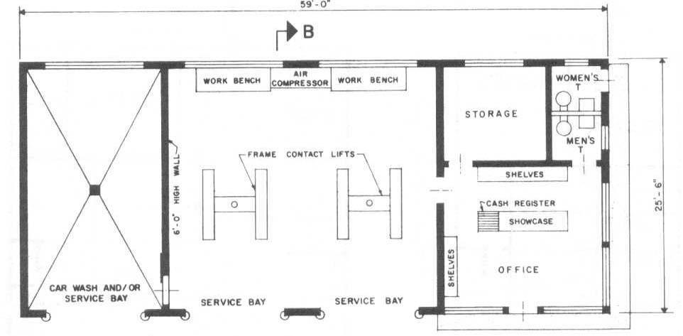
• Wash room: For every 40 passengers in peak hour, 1 wash room should be provided in which ratio for male and female is 2:3.
• Utilities on the float include potable water, sewer, shore power, float lighting, security, passenger control and communications. Emergency power should be provided by a diesel generator sized to power-up the facility such that it is functional during a natural disaster. This generator may be located in the terminal building or on the float pending local ordinances and other considerations. All utilities must conform to the applicable codes and standards which will be named in the specification as the systems are identified. Source: TSS Building Types.pdf)
2.17.2. SUPPORT FACILITIES
INTER – CITY BUS TERMINAL AT BANEPA Aakash Bhochhibhoya 42
2.17.2.1. MAINTENANCE CENTER
Figure 2-29 : General plan of Maintenance Center
2.17.2.2. FILLING STATION
The size of facilities is determined by location, ease of access, typical traffic flows and competitors. Entrance and exits must allow easy steering onto the site and space is needed for cars to queue while waiting for a vacant pump; it should also be easy to steer away from the pump with no obstruction of exits and good visibility when pulling out onto the road. Good entry/ exit sight lines should be provided. Access may be by one-way flow onto the site or combined in and out routes, depending on the location (e.g. approaching a roundabout).
2.17.2.3. RESTAURANT / FOOD COURT
Eatery facilities are very important part of any organizations. They fulfill the needs of user and as well help in generating incomes. Restaurant, food court and cafes should be designed to accommodate not just for eating but meeting and solitary as well. Tea kitchens and vending machine areas also provide useful space for both relaxing and discussion. Area calculation requirements are done in terms of:
• Volume and types of service
• Amount and size of equipment to be used
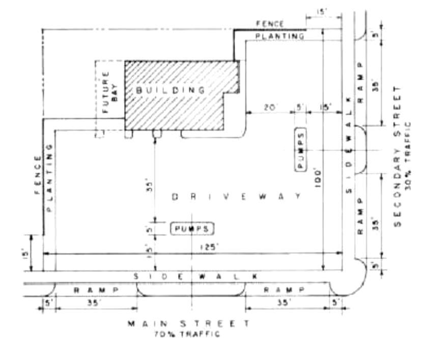
• No. of workers required
• Spaces for needed supplies
• Suitable traffic area
INTER – CITY BUS TERMINAL AT BANEPA Aakash Bhochhibhoya 43
Figure 2-30 : General plan of Filling Station
A food court is a (usually) indoor / semi open plaza or common area within a facility that is contiguous with the counters of multiple food vendors and provides a common area for self-serve dining. Food courts consist of a number of vendors at food stalls or service counters. Meals are ordered at one of the vendors and then carried to a common dining area. Typically food court includes bakery, butcher, cafe bars, snack bars, ice cream, etc.
Traffic aisle
The primary purpose of the traffic aisles is to allow easy movement between the work places, equipment, and functional areas. Since traffic aisles are not productive spaces, they should be kept in minimum no. and size. Traffic aisles should be just enough to provide easy movement of the materials and workers required for efficient operation of the facility.
• The width of the traffic aisles is dependent upon the types of traffic to be accommodated. If it consist only people who are not carrying anything, a min aisles width of 30‖ will allow persons to pass without any difficulties.
• If one worker has to pass another worker pushing a 20‖ wide cart, an aisle width of 44‖ would be needed.
• For the combined work and traffic aisle is needed, a minimum of 42‖ is required to allow one person to pass another person at the work places.
• Aisles having back to back arrangement have to be a min 48‖ wide to allow passage of people between them.
Serving areas
Serving areas for most table service facilities are planned as a part of the main cooking area and separate space determinations are not usually needed. The pickup area is included in the space requirements for the main cooking area. For cafeteria operation require separate space for the serving function to allow room for the serving counter. Serving line rates varies from 2 to 10 persons per minute for straight line cafeteria and the number of server. Food court can handle up to 20 or more persons per minute. The space required for the straight line counters may be roughly estimate at 10 -15 sq. ft. of floor level for each linear foot of counter while food court require 8 sq. ft. of floor area for each seat in the dining area. The flow rate of people leaving the serving areas and entering the dining area should be equal to flow rate of people leaving in the dining area. This relationship can be expressed by the equation.
R= N/T
Where,
• R= rate of people leaving serving areas
• N=No. of seats in dining area
• T= average eating time
INTER – CITY BUS TERMINAL AT BANEPA Aakash Bhochhibhoya 44
Dining areas
Calculating the dining areas can be difficult because of the many choices available. According to the thumb rule, 15sq.ft per seat is required. The final space required for the dining area is dependent upon the following variables:
• Types of seating to be provided
• Table sizes desired
• Table shapes desired
• Pattern of table arrangement
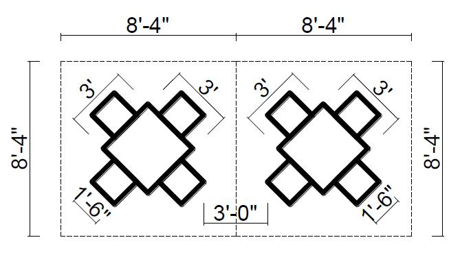
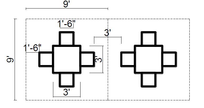
• Aisles space desired
• Number of service stations needed
INTER – CITY BUS TERMINAL AT BANEPA Aakash Bhochhibhoya 45
Figure 2-31 : Module for a square table to be arranged in a rectangular pattern
Figure 2-32 : Module for a square table to be arranged in a diagonal pattern
2.17.2.4. URBAN PLAZA
Plaza is an outdoor public space, free from vehicular movement that provides a space for varying public activities like strolling, sitting, eating, entertaining, passing leisure time, social interaction and watching the world go by. Plazas may have special features like fountains, civic monuments, celebrated building frontage, special lighting and landscape design. The quality of a plaza is determined by the livability and the social interaction that takes place in it, the levels of physical and psychological comfort that it offers, experiences provided to people and the opportunities of engaging in different activities.
In modern usage, a plaza can be any gathering place on a street or between buildings, a street intersection with a statue, etc. Today's metropolitan landscapes often incorporate the "plaza" as a design element. A plaza can be designed as a part of public buildings, which can shift people focus into the building.
Depending upon size, use, relationship to streets, style, predominant function, architectural form, the plazas have been categorized into six major types, which are:
a) Street plaza: A street plaza is a small portion of public open space immediately adjacent to the side walk and in close connection to the street.
b) The corporate foyer: The corporate foyer is a part of any high rise building complex which functions mainly as an elegant entry and image for its corporate sponsor.
c) The urban oasis: The urban oasis is a type of plaza with more park-like image, rendered with excessive greeneries, and partially secluded from the street.
d) The transit foyer: The transit foyer is a plaza type of space created for easy access in and out of heavily used public transit terminals. The subway entry place and the bus terminals are of this type.
e) The street as plaza: The street where vehicular traffic is prohibited, are often used as plaza space where people stroll, sit, eat and watch the activities going on around them.
f) The grand public place: This type of plaza space is often big in size and flexible as well which offers a variety of public activities like a host for lunch crowds, outdoor cafes, passers through, occasional concerts, art shows, exhibitions as well as political rallies. Plazas are located so to be easily accessible to largest number of the potential users are more in use. Visual complexity is one of the most significant components of well-used and most popular plazas among the frequent users. Plazas with visual diversities regarding form, color and texture of various landscape elements: trees, shrubs, fountains, sculptures, variously shaped artifacts, space articulations, nooks, corners and changes in level are more used by people. Also a complex and panoramic view from the plaza is a significant attraction and in such cases the designer's role is to create a setting that capitalizes in that visual asset.
A successful plaza design provides ample seating. Seating allows users to rest, converse, and observe the world. Food is another important aspect which can add extra flavor to the plaza use and
INTER – CITY BUS TERMINAL AT BANEPA Aakash Bhochhibhoya 46
encourages its activity potential. A plaza with a food kiosk or outdoor restaurant is much more likely to attract the users than the one lacking such features.
“If you want to seed a place with activity, put out food. Food attracts people, who attract more people.” – Whyte
People are naturally gravitated to the plazas if some kind of entertaining events are going on in these spaces and the spaces become livelier and exciting.
2.18. ARCHITECTURAL CHARACTER
This Section describes the intent of the architectural goals for the Terminals. Each Terminal should have a distinctive meld of system- wide components and an appropriate character for its site.
• Architectural Character
The Terminals are part of the enduring infrastructure of the Bay Area, and their quality embodies the values of its people. The design of the Terminals should avoid transitory architectural fashions. Terminal designers should strive for sincerity in form, simplicity in articulation, and dignity in materials and colors.
• Identity
The Terminals shall incorporate the system-wide elements including logos, signage, and color, and the passenger services module, including ticket, vending and information kiosk. These elements are essential to orient passengers and the public as they use the Terminals. Each Terminal designer should incorporate system-wide elements into the architecture of each Terminal in a manner to complement its architectural character.
• Adaptation to Communities
Terminal designs should recognize and adapt their character to the communities in which they are located. Communities should be invited to provide special features that recall their heritage and history.
• Roof Shape
The roof shapes establish the presence of the Terminals in their communities from a far. At a distance the roof shapes will be markers orienting communities to the Bay edge, and as destinations along the Shoreline Access. Designers should provide roof shapes that are inviting and that signify shelter and protection from weather. (Source: Pb terminal design guide. pdf)
Bus
terminal and its architectural expression, Architectural importance and characteristics;
A terminal building is the identity of a city because this is the transaction hub from where people from outside the city start visiting the city and people from the city terminate to their destination. So terminal building gives the impression about a city.
And the moment people spend in a terminal building for arriving in and departing from a city should be memorable because those very moments people spend in a terminal building is the last or the
INTER – CITY BUS TERMINAL AT BANEPA Aakash Bhochhibhoya 47
first minutes in a city. So the bus terminal should be an iconic building for the city. Also the location of the bus terminal is very important factor for the development of the city. A bus terminal if properly located can be beneficial for the development of the city. Many cities throughout the world are developing TOD policy. Portland, Montreal, San Francisco, and Vancouver among many other cities have developed, and continue to write policies and strategic plans which aim to reduce automobile dependency and increase the use of public transit.
2.19. TRANSIT ORIENTED DEVELOPMENT
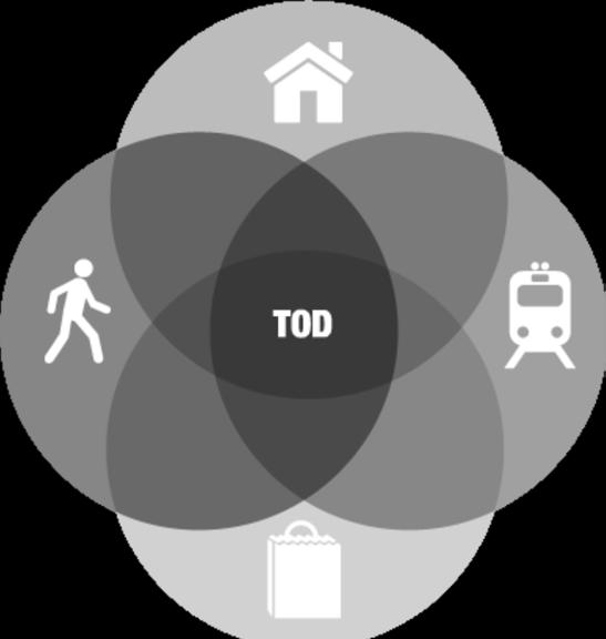
A transit-oriented development (TOD) is a mixed-use residential and commercial area designed to maximize access to public transport, and often incorporates features to encourage transit ridership. A TOD neighborhood typically has a center with a transit station or stop (train station, station, tram, or bus stop), surrounded by relatively high density development with progressively lower-density development spreading outward from the center. TODs generally are located within a radius of onequarter to one-half mile (400 to 800 m) from a transit stop, as this is considered to be an appropriate scale for pedestrians, thus solving the last mile problem.
Transit-oriented development is sometimes distinguished by some planning officials from "transitproximate development" because it contains specific features that are designed to encourage public transport use and differentiate the development from urban sprawl. Examples of these features include mixed-use development that will use transit at all times of day, excellent pedestrian facilities such as high quality pedestrian crossings, narrow streets, and tapering of buildings as they become more distant from the public transport node. Another key feature of transit-oriented development
INTER – CITY BUS TERMINAL AT BANEPA Aakash Bhochhibhoya 48
Figure 2-33 : Transit oriented development
that differentiates it from "transit-proximate development" is reduced amounts of parking for personal vehicles.
Many cities throughout the world are developing TOD policy. Portland, Montreal, San Francisco, and Vancouver among many other cities have developed, and continue to write policies and strategic plans which aim to reduce automobile dependency and increase the use of public transit.
2.19.1. TOD IN DIFFERENT CITIES IN WORLD
Latin America
Guatemala City, Guatemala Curitiba, Brazil
Asia and Oceania
Hong Kong Milton, Queensland
Europe
Paris, France Stedenbaan, The Netherlands
North America
Arlington County, Virginia
Melbourne, Victoria
San Francisco Bay Area, California Salt
Vancouver, British Columbia Toronto, Ontario Calgary, Alberta
Lake City Metro Area, Utah
Montreal, Quebec
Aurora, Colorado
2.19.2. EQUITY AND HOUSING COST CONCERNS
Edmonton, Alberta
One criticism of TOD is that it has the potential to spur gentrification in low-income areas. In some cases, TOD can raise the housing costs of formerly affordable neighborhoods, pushing low- and moderate-income residents farther away from jobs and transit. When this happens, TOD projects can disrupt low-income neighborhoods. When executed with equity in mind, however, TOD has the potential to benefit low- and moderate-income (LMI) communities: it can link workers to employment centers, create construction and maintenance jobs, and has the potential to encourage investment in areas that have suffered neglect and economic depression. Moreover, it is well recognized that neighborhood development restrictions, while potentially in the immediate neighborhood's best interest, contribute to regional undersupply of housing and drive up the cost of housing in general across a region. TOD development reduces the overall cost of housing in a region by contributing to the housing supply, and therefore generally improves equitability in the housing market. TOD also reduces transportation costs, which can have a greater impact on LMI households since they spend a larger share of their income on transportation relative to higher-income households. This frees up household income that can be used on food, education, or other necessary expenses. Low-income people are also less likely to own personal vehicles and therefore more likely to depend exclusively on public transportation to get to and from work, making reliable access to
INTER – CITY BUS TERMINAL AT BANEPA Aakash Bhochhibhoya 49
transit a necessity for their economic success. Another criticism aims the marginal percentage of people actually using public transportation.
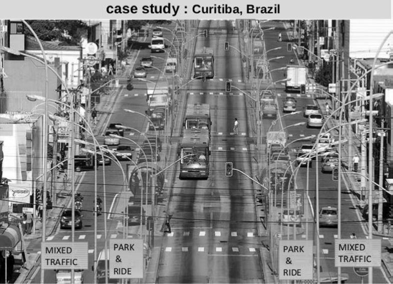
2.20. PARK AND RIDE FACILITIES
Park-and-ride (or incentive parking) facilities are car parks with connections to public transport that allow commuters and other people headed to city centers to leave their vehicles and transfer to a bus, rail system (rapid transit, light rail, or commuter rail), or carpool for the remainder of the journey. The vehicle is stored in the car park during the day and retrieved when the owner returns. Park-and-rides are generally located in the suburbs of metropolitan areas or on the outer edges of large cities. Park-and-ride is abbreviated as "P+R" on road signs, and is also mentioned as P&R in colloquial speech and writing.
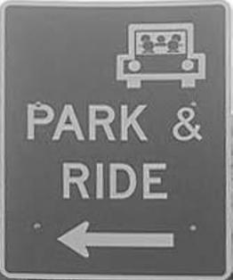
2.20.1. BENEFITS AND CRITICISM
There is a relative paucity of research on the benefits and disadvantages of parkandride schemes, which are often marketed as a way to avoid the difficulties and cost of parking in the city center, but it has also been suggested that there is "a lack of clear-cut evidence for park-and-ride's widely assumed impact in reducing congestion".
INTER – CITY BUS TERMINAL AT BANEPA Aakash Bhochhibhoya 50
Figure 2-34 : Park and ride pattern in Curitiba, Brazil
In theory, park-and-ride facilities allow commuters to avoid the stress of driving a congested part of their journey and facing scarce, expensive city-center parking. They are meant to avoid congestion by encouraging people to use public transport as opposed to their own personal vehicles. They do so by making it easier for people to use public transport in an urban area with traffic congestion, and often to reduce the availability of car parks to encourage this behavior.
Park-and-ride facilities serve the needs of commuters who live beyond practical walking distance from the railway station or bus stop which offers service to the city center Park-and-ride facilities may suit commuters with alternative fuel vehicles, which often have reduced range, since the facility may be closer to home than the ultimate destination. They also are useful as a fixed meeting place for those car sharing or carpooling or using kiss and ride (see below). Also, some transit operators use park-and-ride facilities to encourage more efficient driving practices by reserving parking spaces for low emission designs, high-occupancy vehicles, or car sharing. Most facilities provide services such as passenger waiting areas and toilets. Travel information, such as leaflets and posters, may be provided. At larger facilities, extra services such as a travel office, food shop, car wash, cafeteria, or other shops and services may be provided. These are often encouraged by municipal operators to improve the attraction of using park and ride.
In Sweden, a tax has been introduced on the benefit of free or cheap parking paid by an employer, in situations in which workers would otherwise have to pay. The tax has reduced the number of workers driving into the inner city, and increased the usage of park-and-ride areas, especially in Stockholm. The introduction of a congestion tax in Stockholm has further increased the usage of park and ride.
In Prague, park-and-ride car parks are established near some metro and railway stations (ca 17 parks near 12 metro stations and 3 train stations, in 2011). These car parks offer low prices and all-day and return (2× 75 min) tickets including the fare for the public transport system.
2.20.2. THE DIFFERENT TYPES OF PARK AND RIDES ARE
• Bus park and rides
Park-and-ride facilities, with dedicated car parks and bus services, began in the 1960s in the UK. Oxford operated the first such scheme, initially with an experimental service operating part-time from a motel on the A34 in the 1960s and then on a full-time basis from 1973. Better Choice Parking first offered an airport park-and-ride service at London Gatwick Airport in 1978.
• Railway park and rides
Some railway stations are promoted as a park-and-ride facility for a distant town, for instance Liskeard for Looe and Lelant Saltings for St Ives, both in Cornwall, England. Stations in the UK with large car parks outside the main urban area are often suffixed with "parkway", such as Bristol
INTER – CITY BUS TERMINAL AT BANEPA Aakash Bhochhibhoya 51
Parkway, Tiverton Parkway, and Didcot Parkway. At Luton Airport Parkway and Southampton Airport Parkway, the stations are designed to serve air as well as road passengers.
In the United States, it is common for outlying rail stations to include automobile parking, often hundreds of spaces. Boston, for example, has built several large parking facilities at its commuter rail and metro stations near major highways and large arterial surface roadsaround the periphery of the city: Alewife, Braintree, Forest Hills, Hyde Park, Quincy Adams, Riverside, Route 128, Wellington, and Woburn. The local transit operator, the MBTA, offers 46,000 park-and-ride spaces.
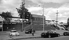
• Bike and ride
B & R (B + R) is a name for using cycle boxes or racks near public transport terminals, mostly together with P & R car parks. This system can be promoted through integrated fare and tickets with public transport system.
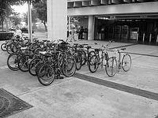
• Kiss and ride
Many railway stations and airports feature an area in which cars can discharge and pick up passengers. These "kiss-and-ride" facilities allow drivers to stop and wait, instead of the longerterm parking associated with park and- ride facilities.
Some high-speed railway stations in Taiwan have signs outside stations reading "Kiss and Ride" in English, with Chinese characters above the words that read "temporary pick-up and drop-off zone".
Most people in Taiwan have no idea what the colloquialism in English means.
Deutsche Bahn has announced that it will be changing the English expressions for Kiss and Ride, Service Points and Counters to German ones.
The term first appeared in a 20 January 1956 report in the Los Angeles Times.
INTER – CITY BUS TERMINAL AT BANEPA Aakash Bhochhibhoya 52
Figure 2-35 : Park and ride lot adjacent to the MTADongan Hills railway
Figure 2-36 : A busy bike-and-ride facility at a Miami Metrorail heavy-rail station.
2.21. FUNCTIONAL TECHNOLOGICAL ISSUES
2.21.1. TECHNIQUES FOR COMMUNICATING WITH PERSONS WITH DISABILITIES
The communication techniques and technologies represent a cross section of those being used within transit stations and terminals, on platforms, and on transit vehicles by transit staff and individuals.
The introduction and implementation for each technology or method of communication varies However, all have been initiated within the past 20 years. A large portion of the audio technology and techniques presented in the research was introduced in the mid-1980s and early 1990s, whereas the AVL and Geographic Information System (GIS)-based technologies have only recently been implemented in several transit systems.
• Non-electronic communication
• Telephone devices
• Tactile technologies
• Audio techniques and technologies
• Smart or computerized technologies
2.21.1.1. NON – ELECTRONIC COMMUNICATION
Non-electronic communication refers to techniques to improve communication that do not require technical support and are person-driven.
• Destination Card Programs
Destination card forms filled out by riders or persons assisting riders contain information about the person's specific disability as well as information about the passenger's desired destination.
• American Sign Language
The majority of deaf people in the United States use this language. Some agencies provide staff members, such as drivers and ticket agents, with training in sign language. This improves communication between staff and hearing-impaired passengers.
• Route Cards
Passengers at bus stops display the card that identifies their desired route. The driver of an approaching bus traveling that route will stop for the passenger.
• Orientation Cues
Orientation cues help persons with visual impairments to orient themselves and distinguish pathways. These cues may include changes in illumination levels, bright colors, unique patterns, and the location of special equipment or other architectural features.
INTER – CITY BUS TERMINAL AT BANEPA Aakash Bhochhibhoya 53
• Braille Writing
The American Foundation for the Blind estimates that less than 15 percent of all persons with a significant vision loss can read braille (1). Growth in the availability of assistive communication technologies has continued to lessen the reliance on braille. Therefore, braille should be provided to complement other methods of communication, rather than as the primary method of communication for persons who are visually impaired.
2.21.1.2. TELEPHONE DEVICES
• Help Phones
Provide orientation and way-finding information by providing passengers with a verbal description of a building's major characteristics or by identifying where facilities are in relation to the passenger's current position. Help phones are generally placed inside terminal buildings and on platform areas.
• Hearing Aid Compatible Telephones
These phones convert sound into magnetic energy when used with a compatible hearing aid and convert that energy back into sound through a flux coil located inside the telephone handset.
• Automated Voice Message Systems
Many transit agencies use automated voice message systems to offer users pretrip information. The most basic systems are computerized databases that give customers information about services offered, such as routes, schedules, and fares, when they call the transit authority.
2.21.1.3. TACTILE TECHNOLOGIES
• Tactile Maps
Tactile maps consist of a combination of braille and large print that transform printed maps into useful tools for the visually impaired. An audio signal may be used to indicate the location of the tactile map, and different textures are used to identify various features of the environment.
• Tactile Signs
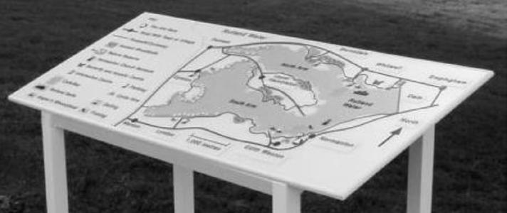
INTER – CITY BUS TERMINAL AT BANEPA Aakash Bhochhibhoya 54
Figure 2-37 : Tactile maps
These signs contain raised letters or characters that can be read by persons who are visually impaired. The signs are typically located at bus stops, information kiosks, and customer information centers.
• Tactile Pathways and Detectable Warnings
Tactile pathways are textured and surface designed to be detectable by foot or cane and distinct from the surrounding surface area. Textured surfaces assist those with visual, orientation, and mobility impairments in a transit environment.
2.21.1.4. ELECTRONIC INFORMATION SYSTEMS
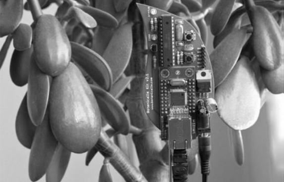
Electronic information signs can convey information and announcements to all sighted passengers and are the best means of providing infrequent information that has traditionally been verbalized, such as notices about train delays.
• Light Emitting Diodes (LED)/Liquid Crystal Display (LCD)
LEDs and LCDs are reader boards using either single or multicolored lettering. They can provide a two-dimensional array of display letters, numbers, or symbols and allow some animation depending on the system capabilities.
• Video/Television Monitors
In a transit environment video/television monitors are the most effective means of providing detailed and continuous information regarding schedules, routes, etc. Monitors can be easily programmed and updated regularly from a centralized computer.
• Captioning
Captioning translates the audio portion of a video into visible subtitles or captions. All information that provides essential messages such as emergency information should be captioned. Captioning devices are generally found inside terminal buildings.
• Visual Alerting Devices
INTER – CITY BUS TERMINAL AT BANEPA Aakash Bhochhibhoya 55
Figure 2-38 : Tactile Pathways and Detectable Warnings
These devices convert sounds such as telephone rings and alarms to visual signals. Visual alarms should be used with audible alarms, especially in main concourses and washrooms of terminal buildings. These devices are very important for a person with a hearing impairment, because they provide a visual form of communicating emergencies.
Electronic information systems are an important component of the communication system of a transit agency. They are helpful to the general public but are of added importance to passengers with disabilities, particularly those with hearing impairments. Therefore, transit agencies should ensure that signs are consistent and uniform in design, are placed in an accessible location, and use proper illumination, color, and brightness to avoid confusion.
2.21.1.5. AUDIO TECHNIQUES AND TECHNOLOGIES
One significant issue facing transit operators is complaints about the inconsistency in announcing major stops, transfer points, and stop requests. This is in violation of the ADA, which requires that major stops and other related announcements be made on fixed-route systems.
• Voice Enunciator Systems
These systems provide announcements in a human voice, and may be triggered by the approaching vehicle to notify passengers of the arrival of a bus or train. Some voice enunciator systems can be set to activate when the bus door opens to broadcast the route number and destination of the bus to passengers waiting at the stop. This is particularly useful for passengers who are visually impaired.
• Talking Signs
Talking signs provide an audio message that allows persons who are visually impaired to orient themselves in the same way as a sighted person looking at a sign. An infrared transmitter is built into the base of a talking sign and when a small, handheld receiver is aimed at the sign, it activates and transmits identifying messages. Found in the immediate area, such as a reception desk, public telephones, elevators, or directional information routinely found on printed signs.
• Talking Buses/Trains
These information systems use digital speech to announce destinations, stops, and intersections. The system can be programmed to automatically announce a message when the door opens, and is activated by pole transmitters located along the route or by other automatic vehicle location devices.
• Auditory Pathways/Acoustical Finders
Auditory pathways and acoustical finders consist of a series of speakers positioned along a predetermined route, which can be electronically activated by depressing a button or by means of an object worn by a passenger that activates a sensor on the speakers. Once the speakers are activated, they will announce instructions that guide the person to their destination. Another form of auditory pathways found on transit vehicles provides instructions when travelers press a button located at the entrance of the vehicle.
• Auditory Beacons or Signal
INTER – CITY BUS TERMINAL AT BANEPA Aakash Bhochhibhoya 56
These signals are emitted from transmitters located directly over open doors. They are used to prevent people from stepping in the gaps between subway cars and station platforms. This is especially useful for passengers with visual impairments.
• Audible Alarms
Audible alarms transmit an alarm sound during an emergency. "Where possible, the alarm should be placed immediately above an emergency exit door".
2.21.1.6. SMART OR COMPUTERIZED TECHNOLOGIES
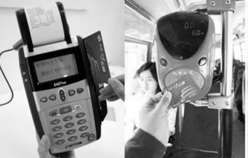
• Smart Cards
Smart cards are cards encoded with an integrated circuit. This circuit contains information that can be securely and read by receptive terminals. Currently there are two types of smart cards, "contact cards," which require direct contact with the receptive terminal, and "contactless" or proximity cards, where activation occurs through a radio frequency inductive field. The combo-card is a recent innovation in smart card technology that combines the characteristics of both the contact and contactless cards. Smart cards provide the opportunity to make machines more users friendly.
• Automated Information Kiosk
The automated information kiosk is a system being developed that enables travelers to retrieve information from both static and real-time databases. Information on local restaurants, hotels, and points of interest is derived from the static database. The real-time data for travel comes directly from a transit operations center.
• Automatic Vehicle Location (AVL)
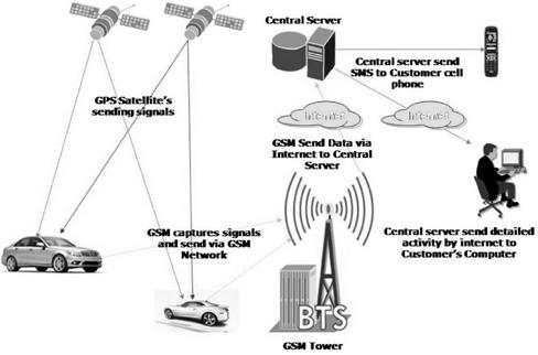
INTER – CITY BUS TERMINAL AT BANEPA Aakash Bhochhibhoya 57
Figure 2-39 : Smart Cards
Figure 2-40 : Automatic Vehicle Location
AVL systems are computer-based vehicle tracking systems. This is made possible through GISs, which are a special type of computerized database management system in which geographic databases are related to one another by means of a common set of locational coordinates. In a transit application, this system gives transit agencies the ability to accurately respond in real-time to passenger inquiries regarding bus location and schedule information. The installation of on-board information display and annunciation technology is usually made possible through AVL systems.
2.21.2. DESIGNING FOR DISABLES
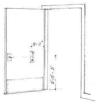
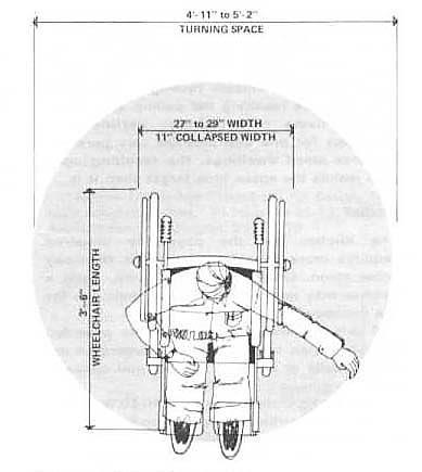
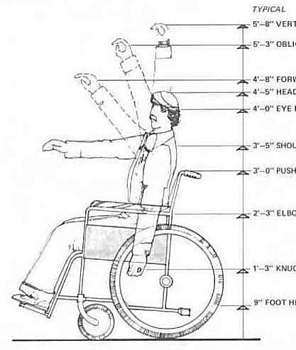
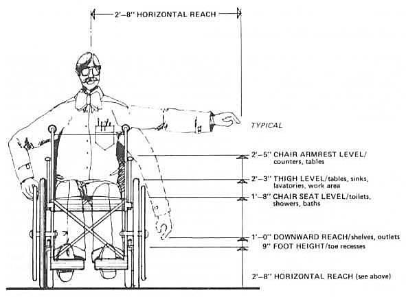
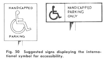
INTER – CITY BUS TERMINAL AT BANEPA Aakash Bhochhibhoya 58
Figure 2-41 : Suggested international signs for accessibility
Figure 2-42 : General anthropometric data’s for wheel chair
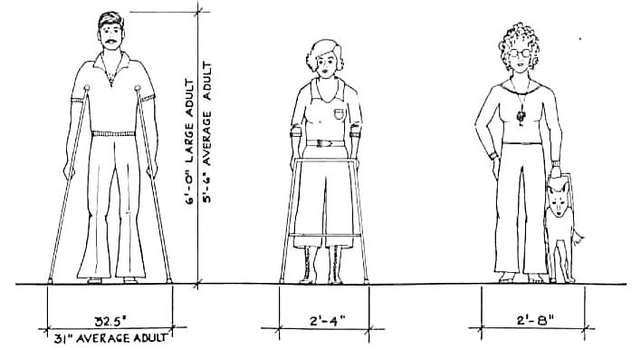
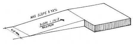
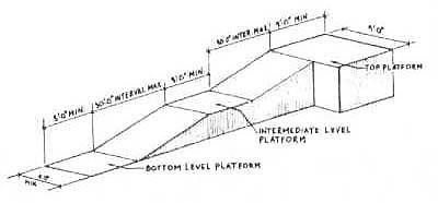
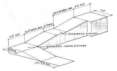
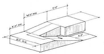
INTER – CITY BUS TERMINAL AT BANEPA Aakash Bhochhibhoya 59
Figure 2-43 : General anthropometric data’s for disable Users
Figure 2-44 : Different layouts of ramp
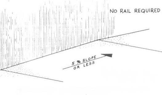
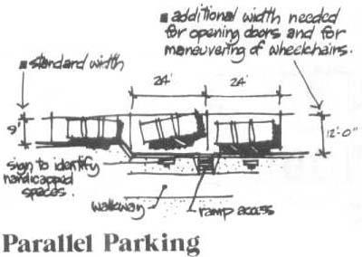
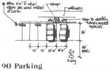
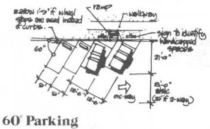
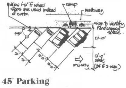
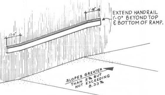
INTER – CITY BUS TERMINAL AT BANEPA Aakash Bhochhibhoya 60
Figure 2-45 : Slope for disabled
Figure 2-46 : Parking requirement for different angles
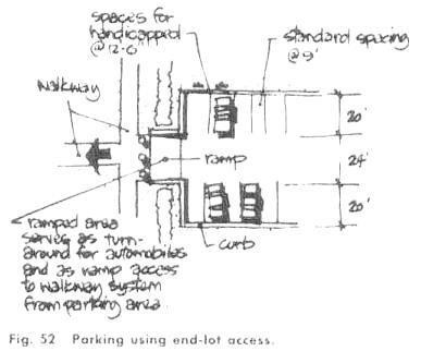
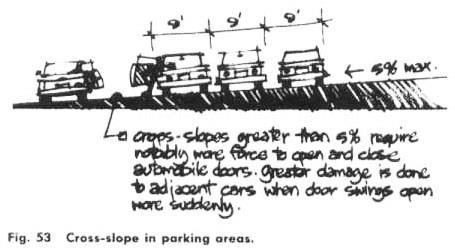
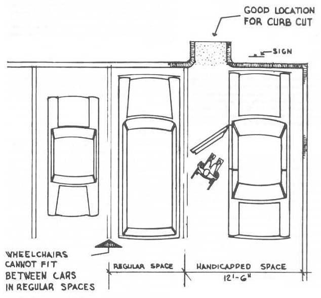
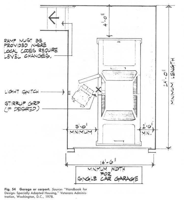
INTER – CITY BUS TERMINAL AT BANEPA Aakash Bhochhibhoya 61
Figure 2-47 : Parking using end lot access
Figure 2-48 : Parking area for wheel chair users
2.22. ENVIRONMENT AND ENERGY CONSIDERATIONS
2.22.1. GREEN ARCHITECTURE
Definition:
Green architecture, or green design, is an approach to building that minimizes harmful effects on human health and the environment. The "green" architect or designer attempts to safeguard air, water, and earth by choosing eco-friendly building materials and construction practices.
Green architecture may have many of these characteristics:
• Ventilation systems designed for efficient heating and cooling
• Energy-efficient lighting and appliances
• Water-saving plumbing fixtures
• Landscapes planned to maximize passive solar energy
• Minimal harm to the natural habitat
• Alternate power sources such as solar power or wind power
• Non-synthetic, non-toxic materials
• Locally-obtained woods and stone
• Responsibly-harvested woods
• Adaptive reuse of older buildings
• Use of recycled architectural salvage
• Efficient use of space
While most green buildings do not have all of these features, the highest goal of green architecture is to be fully sustainable.
Green architecture, philosophy of architecture that advocates sustainable energy sources, the conservation of energy, the reuse and safety of building materials, and the siting of a building with consideration of its impact on the environment.
2.22.1.1. Green design takes root
By the mid-1980s and continuing through the ‘90s, the number of environmental advocacy societies radically expanded; groups such as Greenpeace, Environmental Action, the Sierra Club, Friends of the Earth, and the Nature Conservancy all experienced burgeoning memberships. For architects and builders a significant milestone was the formulation in 1994 of Leadership in Energy and Environmental Design (LEED) standards, established and administered by the U.S. Green Building Council. These standards provided measurable criteria for the design and construction of environmentally responsible buildings. The basic qualifications are as follows:
INTER – CITY BUS TERMINAL AT BANEPA Aakash Bhochhibhoya 62
1. Sustainable site development involves, whenever possible, the reuse of existing buildings and the preservation of the surrounding environment. The incorporation of earth shelters, roof gardens, and extensive planting throughout and around buildings is encouraged.
2. Water is conserved by a variety of means including the cleaning and recycling of gray (previously used) water and the installation of building-by-building catchments for rainwater. Water usage and supplies are monitored.
3. Energy efficiency can be increased in a variety of ways, for example, by orienting buildings to take full advantage of seasonal changes in the sun‘s position and by the use of diversified and regionally appropriate energy sources, which may be depending on geographic location that include solar, wind, geothermal, biomass, water, or natural gas.
4. The most desirable materials are those that are recycled or renewable and those that require the least energy to manufacture. They ideally are locally sourced and free from harmful chemicals. They are made of nonpolluting raw ingredients and are durable and recyclable.
5. Indoor environmental quality addresses the issues that influence how the individual feels in a space and involves such features as the sense of control over personal space, ventilation, temperature control, and the use of materials that do not emit toxic gases.
6. Alternative energy sources. Whenever feasible, build homes and communities that supply their own power; such buildings may operate entirely off the regional power grid, or they may be able to feed excess energy back onto the grid. Wind and solar power are the usual alternatives.
7. Energy conservation. Weatherize buildings for maximum protection against the loss of warm or cool air. Major chemical companies have developed responsibly manufactured, dependable, moisture-resistant insulating materials that do not cause indoor humidity problems. Laminated glass was also radically improved at the end of the 20th century; some windows provide the same insulation value as traditional stone, masonry, and wood construction. In regions that experience extreme heat, straw-bale or mud-brick construction used since ancient times is a good way to save money and energy.
8. Reuse of materials. Use recycled building materials. Although such products were scarce in the early 1990s, since the early 21st century they have been readily available from a burgeoning number of companies that specialize in salvaging materials from demolition sites.
9. Careful siting. Consider using underground or earth-sheltered architecture, which can be ideal for domestic living. Starting at a depth of about 1.5 meters (5 feet) below the surface, the temperature is a constant 52 °F (11 °C) which makes the earth itself a dependable source of climate control. Individual, corporate, and governmental efforts to comply with or enforce LEED standards include recycling at household and community levels, constructing smaller and more efficient buildings, and encouraging off-the-grid energy
INTER – CITY BUS TERMINAL AT BANEPA Aakash Bhochhibhoya 63
supplies. Such efforts alone cannot preserve the global ecosystem, however. On the most basic level, the ultimate success of any globally sanctioned environmental movement depends as much on its social, psychological, and aesthetic appeal as on its use of advanced technologies.
Traditional and innovative technologies that can be used for the decision of a problem of environmental contamination.
• Additional gardening (a spruce fir, a Canadian maple, a Canadian poplar, a trumpet honeysuckle) makes positive impact on quality of air
• Noise barrier of polycarbonate along the Communistic avenue protect for harmful influence of noise.
• Barriers with vertical gardening protect a housing estate and environment for harmful influence of gases
• Lawn lattices on parking‘s also improve air.
• Columns of shelters are ventilating apertures. Moving buses create a powerful wave of air. The dust and gases get to the ventilating chamber through these apertures and exhaust convector clears air. Thus, the hotbed effect decreases.
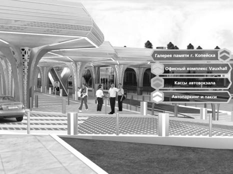
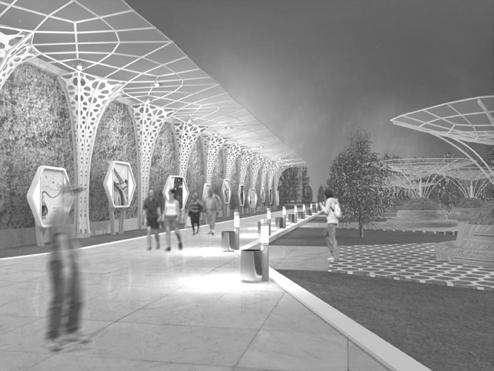
INTER – CITY BUS TERMINAL AT BANEPA Aakash Bhochhibhoya 64
Figure 2-49 : Barriers with vertical gardening
Figure 2-50 : Lawn lattices on parking’s
• The multipurpose flat shelter is a zone of rest for passengers and visitors of business center.
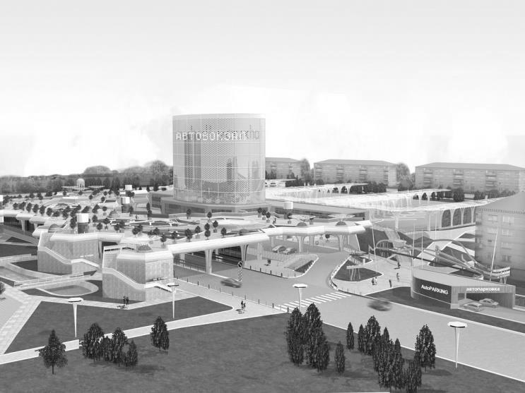
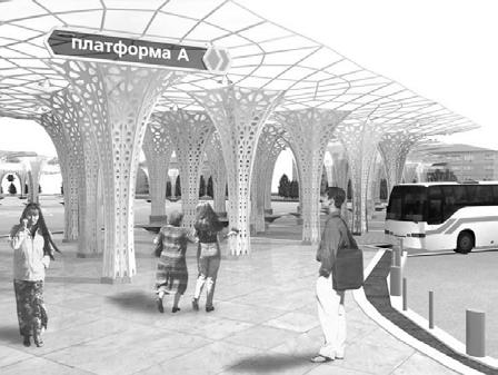
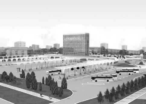
• Rain water from shelters gathers in the tank and is used in the technical purposes.
• PVC material is used for a covering of platforms. There are tectonic blocks under this covering. They react to step-by-step loading. (Crowd Farm this invention of graduates MIT James Graham and Thaddeus Jusczyk). Electric energy is accumulated and used for illumination on a night-time.
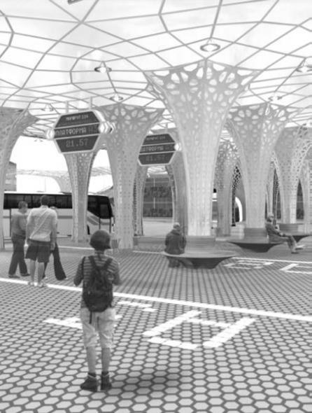
• Power saving up light sources are used for illumination on a night-time.
• The facade of building of ventilated facades and vertical gardening (a cowberry ordinary).
INTER – CITY BUS TERMINAL AT BANEPA Aakash Bhochhibhoya 65
Figure 2-51 : Ventilating chambers
Figure 2-52 : Multipurpose shelter
• Self-cleared glass is used in connection with the raised pollution of a façade (Pilkington Active). This glass of neutral coloring with a special covering provides self-cleaning for organic pollution.
2.22.2. GREEN MATERIALS (GREEN CONCRETE)
Concrete is the most popular and used building materials in the world today. The major environmental impact of concrete is the percentage of cement used in it. It was noted that the world‘s yearly production of cement is about 1.6 billion tons, which doles out 7% of the global loading of carbon dioxide into the atmosphere- a real environmental hazard. The important aspect of making
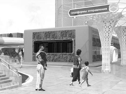
INTER – CITY BUS TERMINAL AT BANEPA Aakash Bhochhibhoya 66
Figure 2-53 : Power saving lights
Figure 2-54 : Ventilated faces with vertical gardening
concrete green is replacement of cement in concrete by suitable pozzolan. At this point, fly ash comes as the first alternative.
Fly ash, sometimes referred as pulverized ash, is a waste product that results from the burning of coal or lignite. In Nepal, much of it is found in brick kilns were coal is ignited to burn bricks. Since it is a waste material, it pollutes the environment and requires appropriate disposal. However, these problems can be alleviated if fly ash is used as a pozzolan.
Fly ash can be utilized as cement replacement because it contains silica in amorphous state that is reactive. When cement reacts with water, cement undergoes a chemical reaction that produces two major compounds, calcium silicate hydrate (CSH) and calcium hydroxide. Calcium hydroxide is usually deposited in the interface between the aggregate and the matrix. Matrix refers to materials other that aggregate that constitute concrete. Therefore, when pozzolans, which have reactive silica, are added as cement replacements, silica reacts with calcium hydroxide to form CSH. CSH is the compound responsible for strength development in concrete. Hence, concrete of higher compressive strength is achieved. Moreover, fly ash makes concrete acid-resistant. Normally, concrete without pozzolans produce only calcium hydroxide when combined with water. Since calcium hydroxide is an alkaline compound, concrete becomes susceptible to acid. However, when fly ash is added, silica reacts with calcium hydroxide to form CSH resulting in less calcium hydroxide. Thus, concrete performs better against acid attack.
The use of fly ash as pozzolan has been adjudged as more effective based on the workability, setting time, bleeding, pump-ability, heat hydrant, and permeability. Because of the spherical shape of its particle and its low specific gravity, fly ash permits greater workability than conventional concrete mixes at a given water-cement ratio. It produces paste with improved plasticity and cohesiveness.
Fly ash has tendency to increase the setting time of concrete because of the slower hydration of fly ash particles; an advantage when concrete has to be transported through long hauls. Bleeding may be defined as the appearance of water on the surface of concrete after it has been consolidated but before it sets. Bleeding is usually reduced with concrete containing fly ash because of the greater volume of its fines and lower water content for a given degree of workability. Besides, pump-ability is increased with concrete that contains fly ash because of the increased ratio of solids to liquids and the lubricating effect of the spherical fly ash particle. When cement reacts with water, an exothermic reaction takes place that liberates heat. When certain part of cement is replaced with fly ash, it tends to slow down this chemical reaction and generates less heat per unit of time. This in turn helps minimize risks of thermal cracking in structures. Besides, fly ash reacts with lime and generates additional cementing compound that block bleed channels, filling pore space, and hence, reduce the permeability of the hardened concrete. Thus, cement can be replaced by fly ash in concrete. It is in usual practice to reduce up to 40% of cement by fly ash. The compressive strength of concrete with 40% fly ash is comparable to or even better performing than conventional mixes at 28 days of curing and usually higher at later ages.
INTER – CITY BUS TERMINAL AT BANEPA Aakash Bhochhibhoya 67
Replacing 40% of cement by fly ash in concrete reduces the cost by 30% and the compressive and flexural strengths are increased by up to 20%. Thus, fly ash is becoming very popular all around the world. In context of Nepal too, the fly ash which is considered as waste in brick factories can be used in concrete replacing cement. Thus, the concrete can be made green having both environmental as well as economic benefits.
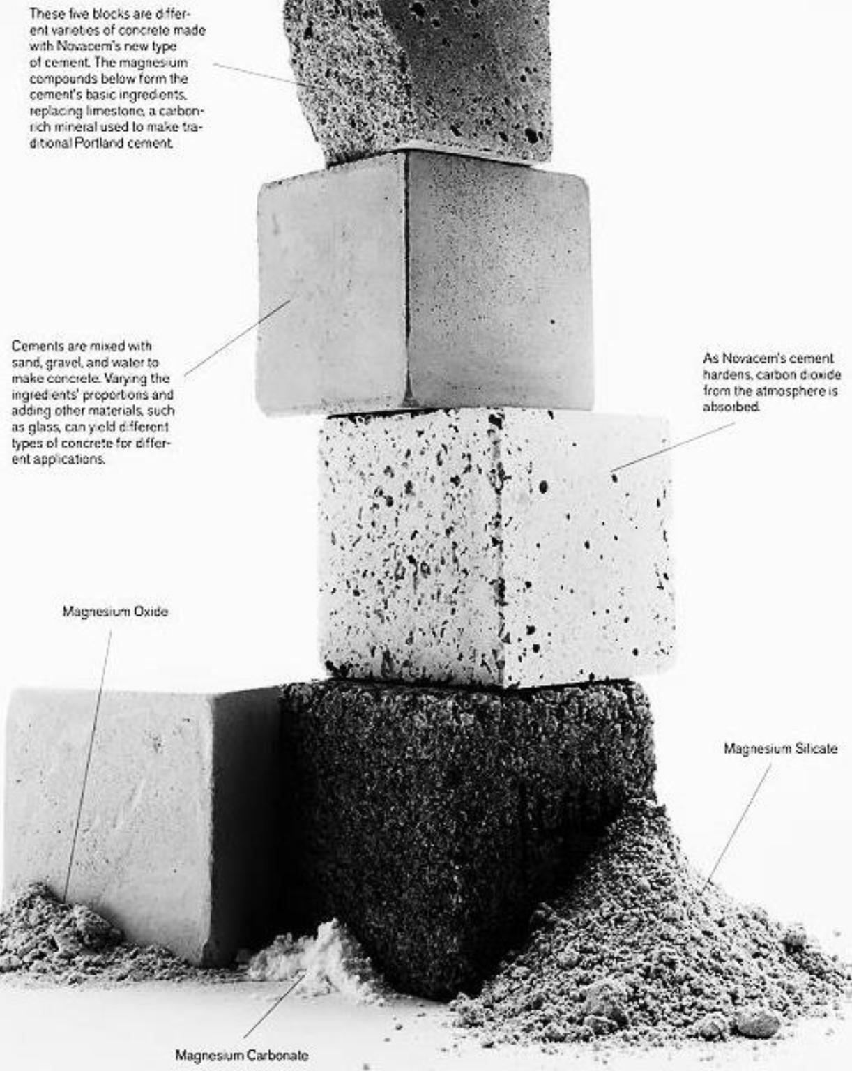
INTER – CITY BUS TERMINAL AT BANEPA Aakash Bhochhibhoya 68
Figure 2-55 : Types of green concrete to reduce the carbon content in the conventional
2.22.3. GREY WATER TREATMENT
Grey water treatment can be defined as any wastewater produced, excluding sewage. The main difference between grey water and sewage is the organic loading. Sewage has a much larger organic loading compared to grey water. It can be treated naturally as well as through clivus grey water management fabric filter. In this filter grey water is passed then it is filtered over here and filtered water is conveyed through the other pipe for irrigation purposed, flushing purpose etc. this could be better understood by following figure.
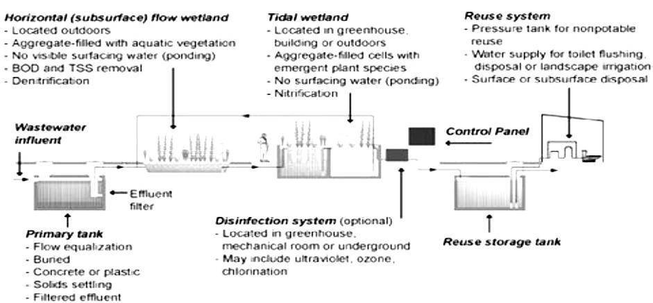
2.22.4. GREASE WATER TREATMENT
The maintenance of vehicles in the bus terminal gives out huge amount of grease water. This water is very harmful for the aquatic animals and plants. Thus, is must be treated before draining it to river. The above figure illustrates the process of separation of grease from water.
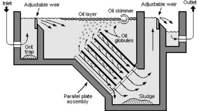
INTER – CITY BUS TERMINAL AT BANEPA Aakash Bhochhibhoya 69
Figure 2-56 : Grey water treatment plant
Figure 2-57 : Grease water treatment plant
2.22.5. USE OF RENEWABLE ENERY: SOLAR ENERGY (PV CELL)
A Solar Energy System is an Alternative Energy System. The basic components required to produce electricity from the sun are; Solar Panels, a Charger Controller, a Power Inverter, and of course, Batteries. All of these components are necessary to have a functioning Solar Electric (PV) system. The solar panel is the basic building block of the system. Several solar modules are wired together to create a solar array. The size of the solar array determines the amount of power or energy that will be produced. The charge controller prevents the solar panel or array from overcharging the battery. Batteries are the energy storage for the system. Without batteries there is no way to store the energy from solar panels.
Typically loads receive their power from batteries instead of directly from the output of a solar panel. A solar panel produces a high voltage that will damage electronics if loads are powered directly. Batteries will provide the energy needed at night. The last major component is the Inverter. The inverter converts the DC energy stored in batteries and turns it into the AC power. Inverters are rated by wattage and the quality of their output. These major components can be put together in many different ways. Minor components like wire, disconnects, circuit breakers, and fuses are also needed for a complete system. Simplicity of the system, it has the lowest cost per watt. The downfall of this system is that when the utility grid fails the system will shut down.
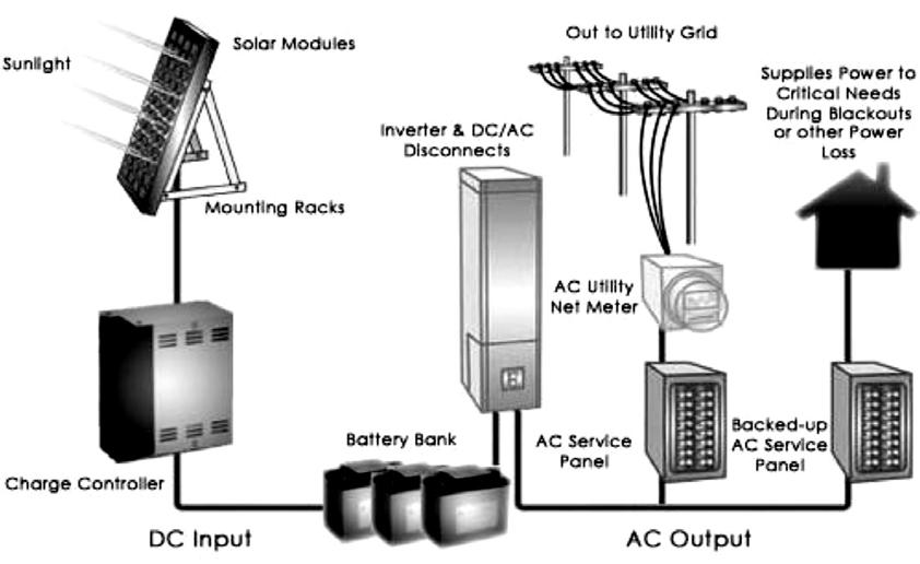
2.22.6. RAINWATER HARVESTING
Rain water harvesting is the technique of collection and storage of rain water at surface or in subsurface aquifers, before it is lost as surface run-off. Rain water can further be used for artificial recharging of ground water. It is a process by which the ground water reservoir is augmented at rate exceeding that under natural conditions of replenishment. Rain water harvesting overcomes the
INTER – CITY BUS TERMINAL AT BANEPA Aakash Bhochhibhoya 70
Figure 2-58 : Solar energy systems
inadequacy of waters, helps maintain water levels. It increases infiltration of rain water in the subsoil which has decreased drastically in urban areas due to paving of open area and improves ground water quality by dilution. Further, it improves ecology of the area by increase in vegetation cover. There are so many Benefits of using rainwater, firstly rainwater is a huge money saver because it falls free from the sky and we can save as much as we like, using it how we want. Rainwater is an environmentally friendly natural resource which is easy to maintain.
Rainwater systems are simple to construct from inexpensive local materials, and are potentially successful in most habitable locations. Roof rainwater can be of good quality and may not require treatment before consumption. However some rooftop materials may produce rainwater that is harmful to human health. There are a number of types of systems to harvest rainwater ranging from very simple to the complex industrial systems. Generally, rainwater is either harvested from the ground or from a roof. The rate at which water can be collected from either system is dependent on the plan area of the system, its efficiency, and the intensity of rainfall.
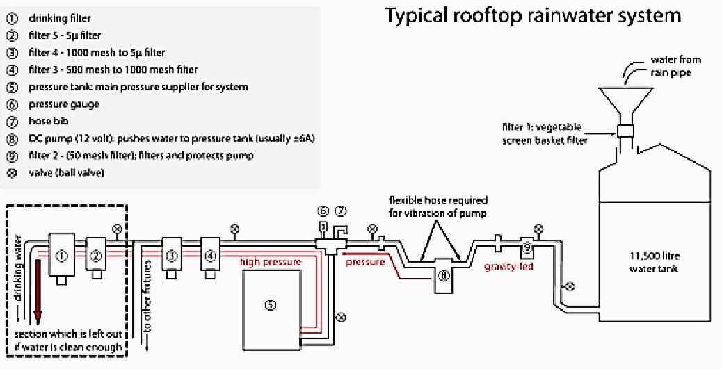
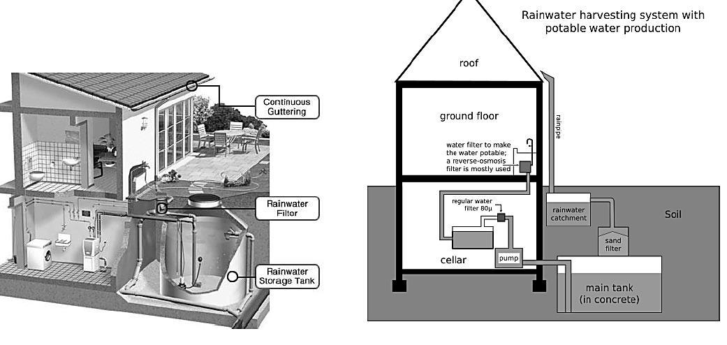
INTER – CITY BUS TERMINAL AT BANEPA Aakash Bhochhibhoya 71
Figure 2-60 : Domestic rain water harvesting
Figure 2-59 : Roof catchment system
Roof catchment systems
Roof catchment systems channel rainwater that falls onto a roof into storage via a system of gutters and pipes. The first flush of rainwater after a dry season should be allowed to run to waste as it will be contaminated with dust, bird droppings etc. Roof gutters should have sufficient incline to avoid standing water. They must be strong enough, and large enough to carry peak flows. Storage tanks should be covered to prevent mosquito breeding and to reduce evaporation losses, contamination and algal growth.
Rainwater harvesting systems require regular maintenance and cleaning to keep the system hygienic and in good working order. As rainwater harvesting machines are also proboscis they should be handled with care.
2.22.7. ATRIUM
The atrium is emerging as one of the most versatile and useful design elements available to contemporary architects. In commercial retail centers, atrium has a distinct marketing advantage, which is the ability to create a kind of captive audience. With all the shops related to the atrium, whether it is linear or vertical, they can be easily accessed. The climate is controlled and the ambience is pleasant, making shopping a pleasure and thereby increasing sales. Although there are many reasons for the current resurgence of atrium buildings, none is more significant than the inherent energy potential of this spatial type. An atrium contributes to passive heating, is useful in an overall ventilation and cooling strategy, and always makes daylight more available to the spaces which surround it. To design an atrium building without making advantage of its inherent energy value is truly to miss an opportunity to create a more complete architecture. Thus, the atrium is one of the generic strategies available to architects and engineers in their quest to provide more energyefficient and environmentally suitable buildings. An atrium designed for energy efficiency should make maximum use of passive energy flows alone or in concert with mechanical energy systems. The passive techniques are:
a. Day-lighting: Effective transmission of natural light and balanced distribution is the key. The value of day-lighting is universal to good architecture. The atrium concept allows the innovative exploration of day-lighting by bringing natural light into the centers of building, thus eliminating deep, dark spaces. The generated interior facades, in tandem with the exterior facades, serve to balance the distribution of daylight within the occupied zones. The use of day-lighting, a free energy source, can offset the cost of electricity, the most expensive energy source. This is particularly appropriate in commercial and institutional buildings where high light levels are required during the daytime. Each unit of artificial lighting energy utilized requires the expenditure of an additional one-half unit of energy for air conditioning to offset the heat generated by the lights, thus compounding the energy usage.
The analysis of day-lighting in atria can be organized around three considerations:
INTER – CITY BUS TERMINAL AT BANEPA Aakash Bhochhibhoya 72
1. Daylight Source: How is the daylight brought into the atrium?
2. Light Box: How is the daylight distributed within the atrium?
3. Illumination: How is the daylight utilized within occupied spaces?
b. Passive cooling: Most atrium buildings are thermally heavy (high internal heat gains) and used during the hottest part of the day, making cooling a very important concern. Cooling requires a higher level of energy expenditure per degree of temperature reduction than does heating per degree of temperature increase. There are potentially four passive cooling techniques available for use in atrium buildings. They are:
1. Control of solar heat gain through shading.
2. Use of thermal mass.
3. Radiative cooling, and
4. Convective cooling based on stack effect.
c. Ventilation: Cross-ventilation and vertical, both natural and mechanically aided is important to maintain required indoor air quality and convective cooling. The location and sizing of vents is the same for thermally driven and wind-induced convection. Exhaust vents should always be at the highest point in the atrium, on the leeward side. Raising the roof of the atrium above the surrounding roofs gives a location for these vents and creates a hot air reservoir which is above the occupied zones. The cool-air intake should be as low as possible and approximately one-third to one-half the area of the exhaust vent.
d. Microclimates: Historical notions about the atrium as garden or courtyard have influenced many contemporary design schemes. Controlling the microclimates at the occupied levels can produce cooling effects. Plants and trees absorb heat and light. Tree canopies produce shade and hold cool air near the ground. Water features such as pools and fountains produce evaporative and radiative cooling in their proximity. These effects can be measured as temperature changes and air movements although in actuality they minute. More significant are the psychological effects, the associations between greenery and water and cool gardens or courtyards.
e. Passive heating: The atrium can contribute to the heating function of the building it serves through passive solar heating. In most commercial, institutional and office buildings, heating is not as significant concern as lighting and cooling because these buildings have a heavy thermal load with large amounts of heat generated by occupants, artificial lighting and office machines. Thus, heating consideration plays tertiary role in the design of atria. An atrium must have south facing glazing in order to contribute to passive solar heating. Skylights are not optimal for they favor the high-angled summer sun. Besides, sunspace can be most effective mode of passive solar heating in the design of atrium. Atrium is an important design element in a building, considering it‘s functional, aesthetical and energy values. Atrium design must also address the context. The form of atrium building needs to be evaluated in terms of its site massing and contextual role; connection to streets, plazas, courtyards, arcades, pedestrian bridges and subways. Further it need to be
INTER – CITY BUS TERMINAL AT BANEPA Aakash Bhochhibhoya 73
evaluated in terms of maximizing public access and use, making it visible by giving it exterior expression, providing public amenities in the form of seating, services, exhibitions, landscaping, and artwork.
2.22.8. POROUS PAVEMENT
A typical side walk, tree box & sewer drain channels the water runoff from the buildings into the sewer, in turn polluting the watershed whereas sustainable porous sidewalk, tree bed and plaza drain and filter water to reservoirs and then filters overflow to sewer drain pipe. Any building construction creates a displacement of natural water systems. The sustainable self-sufficient system is two-fold. The first part reduces the amount of displacement to begin with by maintaining vegetative coverage and infiltrating water that is displaced. The second part is capturing the remaining water that has been displaced and releasing it back into the soil at whatever the normal rate is for that geographic climate. The captured water can be used in many ways contributing to a self-sufficient supply of water for the building.
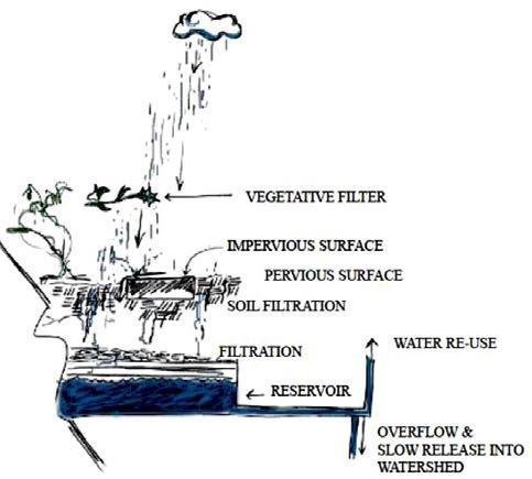
“Porous pavements treat water quality during water’s infiltration and storage in the pavement structure sub grade. In general, porous pavements are effective at treating the particulates, oils, nutrients, and bacteria that occur in the course of pavements‟ normal use and maintenance. The treatment involves the removal of solid particles and their attached ions from water, and bringing oil into contact with microorganisms for biochemical degradation.” (Ferguson 2005, p.153.)
Porous paving is advantageous to safe driving in the rain and cold. Water running off dense, nonporous pavements becomes slippery, and during cold weather the wet surfaces freeze, forming a sheet of ice. Porous pavement drains water away, reducing water sheeting effects. Porous paving provides tire grip due to the coarse quality of the surface. Wet porous paving retains its dry friction value (Ferguson, 2005, p. 499.) Many materials can be used to form porous driving surfaces.
Pervious concrete
Plastic Grids
Porous asphalt
Single-sized aggregate
Porous turf
Permeable interlocking concrete pavements
Permeable clay brick pavements
Resin bound paving
Bound recycled glass porous pavement
INTER – CITY BUS TERMINAL AT BANEPA Aakash Bhochhibhoya 74
CASE STUDY
INTER – CITY BUS TERMINAL AT BANEPA Aakash Bhochhibhoya 75
CHAPTER 3
3. CASE STUDY
Case studies are very much important factor in any field of education and profession. The case study helps to understand the relative subject in deep which takes the form of vital information in the future process of design thinking, planning, and design implementation too. A case study also visualizes how the climatic, cultural and socioeconomic status that helps to influence the architectural components of any building in terms of construction, detailing, material uses and architectural characteristic as well.
In most of the cases, numerous case studies are done to understand the case and the surrounding contexts and also the context of time. The method of case study that I followed is basically called “the funnel approach”. First, I went through the case studies of the international bus terminals to study the present context of the case in the world and also the technologies in prevailing context. Then, I studied the bus terminals in India (Asia-neighboring country) to know the context of planning in Asian society. And then, finally I made a deep study in the bus stations and bus terminals and the vehicular routes in Kathmandu.
The following are the case studies and the reason why I made the decision to choose them as the part of my case study report:
Case study 1: Curitiba, Brazil
To study about sustainable public transport and its impact in the city.
Case study 2: Gongabu Bus Terminal, Kathmandu, Nepal
To study the regional and the present scenario of Bus Terminal in Kathmandu valley.
Case study 3: Bharatpur Bus Terminal, Bharatpur, Nepal
To study the national and the present scenario of Bus Terminal in other part of Nepal.
Case study 4: Banepa Bus Station, Banepa, Nepal
To study the present scenario of Bus Station for the purpose of site study
Case study 5: Geeta Mandir Bus Port, Ahmedabad, India
To study about the ISBT (Inter – State Bus Terminal) in the regional area and to know the result of building a new terminal (completed in 2015) in the existing bus station site.
Case study 6: ISBT Kashmiri gate, New Delhi, India
To study the planning of the facilities in different levels and the segregation of different routes in same level.
Case study 7: Suvarnabhumi Airport, Bangkok, Thailand
To study the structure and its form by use of structure member, and to get knowledge about use of material in true expression.
INTER – CITY BUS TERMINAL AT BANEPA Aakash Bhochhibhoya 76
3.1.
CASE STUDY 1 : CURITIBA, BRAZIL
3.1.1. GENERAL INFORMATION
The station type is Road based bus stop for both long and short route station. The transportation system is BRT i.e. (Bus Rapid Transit). The station is located at Curitiba, Brazil and is constructed in 1974 A.D. by Architect: Jaime Learner, who is urban planner and also had been mayor of Curitiba, Brazil.
Around 70 percent of Curitiba’s commuters use the BRT to travel to work even though Curitiba’s automobile ownership and per capita incomes are significantly higher than the national average for Brazil, resulting in congestion-free streets and pollution-free air for the 2.2 million inhabitants of greater Curitiba. 13
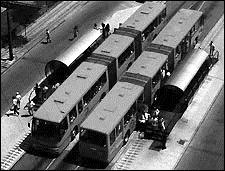
The bus system includes about 60 kilometers [37 miles] of median bus ways and carries about 2 million people per day. The system carries up to 11,100 passengers one way on the busiest bus ways in the peak direction during the peak hour. Bus speeds average 20 kph [12 mph] along the bus way and about 30 kph [19 mph] on the “direct” express routes. Development costs have been estimated at $1.5 million (U.S. dollars) per kilometer [$2.4 million per mile].
The entry and exit is separate. Entry from one side and exit from another. The structure of station is made up of Steel and Glass. It is convenient, well-designed, comfortable, and attractive. During peak hours busses arrive every 60 seconds and are always full. Curitiba has one of the most heavily used, yet low-cost, transit systems in the world 14
INTER – CITY BUS TERMINAL AT BANEPA Aakash Bhochhibhoya 77
13 Moving the Movement for Transportation Justice – Vol. 12 No. 1; Spring 2007
14 Joseph Goodman, M. L. (2005/2006). Curitiba’s Bus System is Model for. Race, poverty & the environment.
Figure 3-1 : Bus Station, Curitiba, Brazil
3.1.2. BACKGROUND

In 2010 the Global Sustainable City Award was given to Curitiba. The award was introduced to recognize those cities that excel in sustainable urban development. It is much easier for cities in the developed world to invest in the planning and implementation of measures needed for sustainable urban development and it is a surprise to many people that the award went to a city in Brazil where, in spite of rapid industrial growth in recent years, income levels are still relatively low. A quick look at the reasons for this reveals Curitiba as a surprising place with an interesting history and culture.
Curitiba is in eastern Brazil and became the capital of the province of Parana in 1853. It attracted local migrants as well as immigrants from Germany, Ukraine and Poland and other European countries. During the 20th century its population increased rapidly and it became one of the wealthiest cities in Brazil. In 2010 the population of Curitiba was 1.8 million and the total population of its metropolitan area was 3.2 million. 15
Curitiba was a pioneer in attempts to provide solutions to improving urban life and the first city plan with boulevards stretching out from a central area, public amenities and industrial districts was produced in the 1950s. 16 The plan was too costly to implement in full but formed the basis for future developments.
15 “Creating a Linear City with Surface Metro – the Story of Curitiba,” Robert Cervero, NTAC, Institute of Urbanand Regional Development, University of California, 1995.
16 Environmental Innovation and Management in Curitiba, .J Rabinovitch and L. Leitmann, UNDP -UNCHS (Habitat)-World Bank, Urban Management and Environment, Working Paper 1, June 1993.
INTER – CITY BUS TERMINAL AT BANEPA Aakash Bhochhibhoya 78
Figure 3-2 : Map of Curitiba, Brazil
The plan for city development that led to its present status as one of the most sustainable cities in the world was a result of the election of a 33-year-old architect and planner, Jamie Lerner, as mayor of Curitiba in the late 1960s. He implemented radical plans for urban land use which featured pedestrianization, strict controls on urban sprawl and an affordable and efficient public transport system. The bus system has been a key feature of Curitiba’s development. 17 The buses are long, split into three sections and stop at designated elevated tubes, complete with disabled access. There is only one price, no matter how far you travel, and you pay at the bus stop. It has been a model for other cities trying to achieve more sustainable movement of people and is used by 85% of people living in the city.
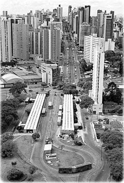
Another feature of the city is the large amount of green space per head of population (52 square meters) which is remarkable in a city that has seen its population triple in the last 20 years. 18 Much of the green space was achieved by using federal funds for flood control to build small dams across rivers, creating lakes and parks for the city population. There are 28 parks and wooded areas in Curitiba, creating a city landscape which is unlike any other in a developing city.
Curitiba does have slum dwellings and housing shortages but has developed innovative ways of dealing with these urban problems. Farmland within the city limits was purchased in the 1990s and 50,000 homes, which will house 200,000 people, are being built. The houses are being built by the new landowners, sometimes with the aid of mortgages from the city. (Joseph Goodman, 2005/2006)
3.1.3. ENVIRONMENTALLY SUSTAINABLE URBANIZATION
3.1.3.1. Energy Efficiency Measures
1. Alternative energy offered to consumers
2. Energy conservation effort (other than green building requirements)
3. Environmental site design regulations
4. Green building program and Renewable energy use by city government
17 Joseph Goodman, M. L. (2005/2006). Curitiba’s Bus System is Model for. Race, poverty & the environment.
18 Innovative Land Use and Transport Policy, the Case of Curitiba, J. Rabinovitch, Land Use Policy, Vol 13, No 1 (02648377(95)00023-2) 1996.
INTER – CITY BUS TERMINAL AT BANEPA Aakash Bhochhibhoya 79
Figure 3-3 : Sustainable transportation of Curitiba
3.1.3.2. Pollution Prevention and Reduction Measures
5. Kerbside recycling program
6. Environmental education programs for the community
7. Green procurement
8. Water-quality protection
3.1.3.3. Open Space and Natural Resource Protection Measures
9. Environmentally sensitive area protection
10. Open space preservation program
3.1.3.4. Transportation Planning Measures
11. Operation of inner-city public transit (buses and/or trains)
12. Transportation demand management
3.1.3.5. Tracking Progress on Protecting the Environment
13. Ecological footprint analysis
3.1.4. ECONOMICALLY SUSTAINABLE URBANIZATION
3.1.4.1. Smart Growth Measures
1. Agricultural protection zoning
2. Brownfield reclamation
3. Cluster or targeted economic development
4. Eco-industrial park development
5. Infill development
6. Purchase of Development Rights and/or Transfer of Development Rights
7. Tax incentives for environmentally friendly development
8. Urban growth boundary and/or urban service boundary
3.1.4.2. Measures Promoting Local Employment/Industries
9. Business retention programs
10. Empowerment/enterprise zones
11. Local business incubator programs
3.1.5. SOCIAL SUSTAINABLE URBANIZATION
1. Affordable housing provisions
2. Daycare services for service sector and low-income employees
INTER – CITY BUS TERMINAL AT BANEPA
80
Aakash Bhochhibhoya
3. Homeless prevention and intervention programs
4. Inclusionary and incentive zoning
5. Jobs-housing balance
6. Living wage ordinance
7. Mass transit access with local income subsidies
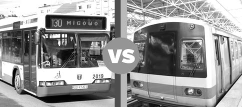
8. Neighborhood planning
9. Sustainable food systems or food security programs
10. Women/minority-oriented business Community Development Corporations (CDCs) and investment programs
11. Youth opportunity and anti-gang programs
3.1.6. GOVERNANCE AND INSTITUTIONAL SUSTAINABLE URBANIZATION
1. Dispute resolution
2. Public participation
3. Regional co-ordination
3.1.7. CURITIBA’S TRANSPORTATION SYSTEM
The process of redesigning Curitiba began by addressing the transportation system in the city. The transportation is viewed as the key to successful integration of Curitiba's residents and attributes. The city has integrated sustainable transport considerations into all of its plans for business development, road infrastructure development and local community development. Due to a limited budget, it was decided not to construct a subway, but rather to convert existing bus lines into fast, efficient and cost effective aboveground transportation. 19
INTER – CITY BUS TERMINAL AT BANEPA Aakash Bhochhibhoya 81
19 Innovative Urban Transportation in Curitiba A Successful Challenge to Conventional Wisdom, Santoro and Leitmann, LACTD Regional Study, May 1996.
Figure 3-4 : Bus lines chosen over Subway in Curitiba
One of the goals specified in the Master Plan of 1965 is to provide access for all citizens. In order to fulfil this goal, the five structural arteries have been modified over time to give public transport the highest priority. Each of the five arteries contains one two-way lane devoted exclusively to express buses. The inner lane is flanked on either side by a local access lane for cars and a highcapacity one-way route for use by both cars and buses. Separating traffic types and establishing exclusive bus lanes in the city's arteries has created a transport system that is characterized by:
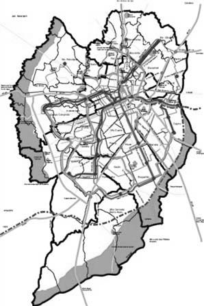
A safe, reliable and efficient bus service operating without the hazards and delays inherent to mixed-traffic bus service
Densification of development along the bus routes.
The Curitiba bus system is an integrated part of the region's transport system and combines eight of the larger cities within the region, called "Grande Curitiba".
The Curitiba bus system uses 1 900 buses to trans- port 1.9 million passengers per day and nearly 70% of the population uses the bus system each day. Furthermore, the bus system covers 65% of the municipality's area. 20
Source: (Rabinovitch J. a., 1996)
The map shows the detail routes of buses including: rapid, bi-articulated, inter-district and feeder with the different routes’ color.
20 Curitiba City web site - www.curitiba.pr.gov.br/inglis/solucoes/transporte.
INTER – CITY BUS TERMINAL AT BANEPA Aakash Bhochhibhoya 82
Figure 3-5 : Curitiba city map showing bus routes
Five different types of buses operate in Curitiba:
The express buses operate only on the arteries' dedicated bus ways


The "rapid" buses (capacity of 110 passengers) operate on the arteries and other main streets. The routes are changed to respond to demand. These buses stop at tube-shaped stations designed for protection from the weather and for quick bus entry and exit. They also accommodates the handicapped.
The "bi-articulated" bus (capacity 270 passengers) is a form of rapid bus operating on the outside high-capacity lanes. This bus type has been developed and adapted in Curitiba.
The "inter-district" buses transports passengers between the city's sectors lying between the arteries, providing an important link between the routes of the express and bi-articulated buses. This bus type also operate on the ring road surrounding the CBD.
The "feeder" buses mix with traffic on all other city streets and bring passengers to transfer stations around which local urban development and commercial activity has flourished.
(“Curitiba Integrated Network, Urban Transportation World Reference.” URBS, Curitiba.)
Table 3-1 : Curitiba’s system: Lines, busses, capacity, fleet. Source: URBS, 2008
The maximum carriage capacity of Curitiba’s bus system is up to 270 by express / bi-articulated line bus route and the minimum is up to 30 by circular Centro / micro line bus route.
INTER – CITY BUS TERMINAL AT BANEPA Aakash Bhochhibhoya 83
Line Capacity Operating fleet No. of lines Circular Centro/Micro 30 09 01 Conventional/MicroMicro Special 40/70 280 89 ConventionalTroncal/Common 80 115 19 Troncal / Articulated 160 24 19 Feeder /CommonMicro Special 80/70 670 212 Feeder / Articulated 160 75 212 Inter-district / Articulated 160 90 06 Express / Biarticulated 270 165 06
3.1.8. SOLVING THE FARE PROBLEM
With the evolution of the transportation system there increased a need for an effective mode of payment. Curitiba’s city hall wanted to expedite bus service and recognized that one of the factors that generated delays is the hold-up in the mode of passenger payment.
The city also had to create a system in which individual bus companies that catered to the various zones in the city could share revenues without competing with each other. Traditionally the city was partitioned in different zones that were serviced by individual bus companies. But, with the creation of the inter-district routes and the implementation of the Integrated Transportation Network along with the unified fare, passengers could pay one company at a terminal located in a particular zone and ride the system without paying the other bus companies. In 1987 the city addressed this problem by distributing transportation revenue based on the number of kilometers traveled by vehicle type for any given company. With each company given a number of route kilometers and a timetable, each company competes with the schedule not with other companies (Rabinovitch and Hoehn, 1995)
3.1.9. SECURITY
With the smart card system, 24/7 surveillance CCTV camera, vibrant space and transparent glass tube, the security of the Curitiba station is maintained. (Zaruch, 1975)
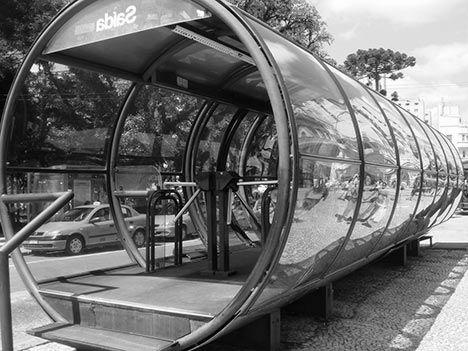
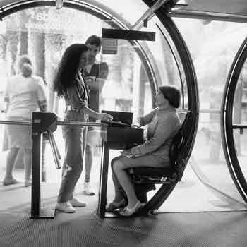
INTER – CITY BUS TERMINAL AT BANEPA Aakash Bhochhibhoya 84
Figure 3-6 : Paying fare inside Tube like structure, Curitiba
Figure 3-7 : Transparent glass tube station, Curitiba
3.1.10. BUS AND STATION DESIGN
After the construction of terminals and the implementation of the unified fare, the city wanted to develop busses and stations designed with the intention of avoiding fare evaders. For this reason, busses are designed with three doors, two doors for exiting and a front door for boarding.
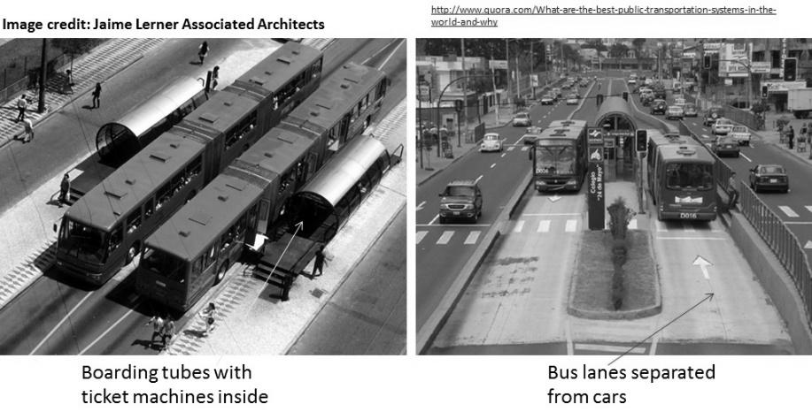
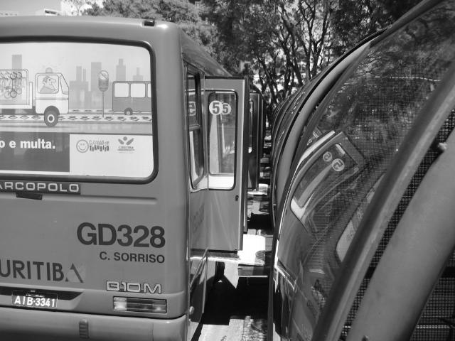
In a category by itself, these urban busses are constructed with turbo engines, lower floor levels, wider doors, and a convenient design for mass transit. Curitiba also developed boarding tube stations that were placed along direct routes and express lanes. To increase convenience, boarding efficiency and reduce fare evaders the tubes elevate passengers to the bus platform level where automatic doors operated by the tube conductor open parallel to the bus doors. Passengers pay an entrance fare at the turnstile and wait for their respective direct or express bus to pass. Disembarking passengers leave the stations through a direct exit. (Rabinovitch
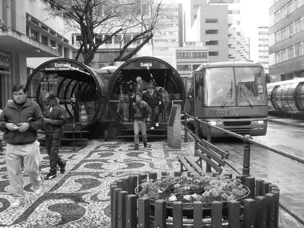
INTER – CITY BUS TERMINAL AT BANEPA Aakash Bhochhibhoya 85
J. a., 1995)
Figure 3-8 : Exiting and boarding in the bus, Curitiba
Figure 3-9 : Direct exit from boarding tube
To further assist passengers, each tube station is equipped with station and route maps and with small lifts situated beside the entrance of the tube to help disabled passengers, strollers, and passengers carrying heavy bags enter the tubes with agility.
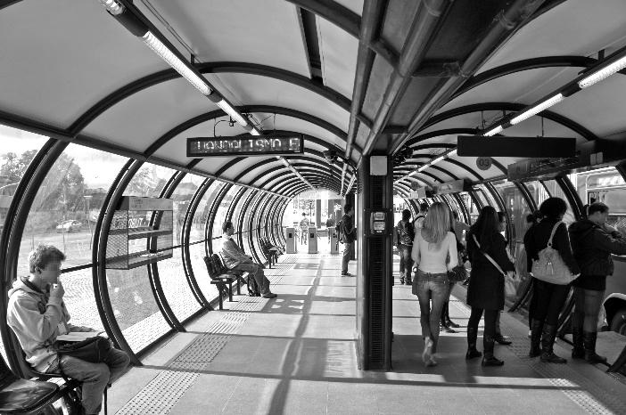
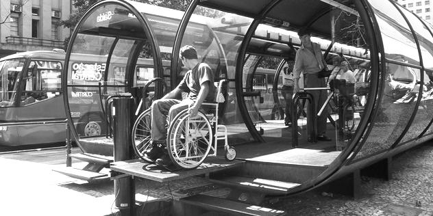
3.1.11. ANALYSIS
Curitiba’s system of transportation is an example of effective urban planning. The city’s urban planners recognized that even if growth in population cannot be controlled, the development of infrastructure in the city can guide the city’s expansion. By approaching transportation as tool used to attain a greater solution rather than as a solution to an advancing problem, they were able to implement an efficiently constructed, cost-effective transportation system that finances itself. The city used busses because it had a tradition of using busses. While this system is powered by diesel, the reduction of the number of cars used compensates, if not surpasses, the difference in carbon monoxide emissions. Like every city, Curitiba’s transportation system is plagued by overcrowded peak hours and untimely busses. But, this is a relatively minor inconvenience in comparison to the service provided and the proximity served. From personal experience I can testify to the agility of this system. In comparison with transportation systems in Rio de Janiero, where passengers have to flag down and run after a number of private busses that provide service to the same destination using different routes and New York City were busses are often caught in unrelenting city congestion for a good part of the working day, Curitiba's integrative bus system with its express lanes and bus expediency, essentially works.
INTER – CITY BUS TERMINAL AT BANEPA Aakash Bhochhibhoya 86
Figure 3-10 : Lift situated for disabled passengers, strollers and heavy bags
Figure 3-11 : Inside tube station
NEED:
It is accessible to all the users including the wheel chair users. The comfort zone inside is optimum. The station is free from accident and crime because of enclosed structure and the door opens only during the bus arrives. The separate entry and exit made the easy processing of passengers.
SIZE:
The sizes differed from number of passengers inside the bus and also inside station. Where number of passengers are high, 2 bays of stations are provides of width 3.5 m each.
In BRT system, station is located road side bus bay and terminals are nearby densely populated areas. It formed a component in the hierarchy of transport systems. It is located in minimum impact area. The concentration and dispersal cost is minimum. It is located such that as point of coordination and integration between intercity and intra-city transport.
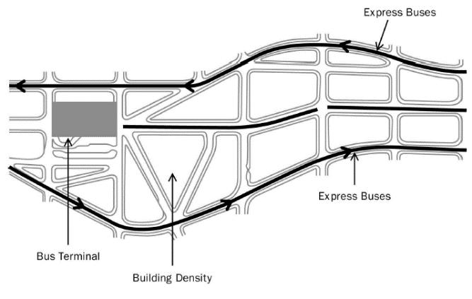
DESIGN
It is well designed that segregate the bus and non-bus traffic through BRT route. Segregation of pedestrian and vehicular movement is maintained. One bus at a time eliminated the vehicular traffic conflict. Minimum processing for buses from BRT route to the terminal is maintained by locating bus terminal in major route access.
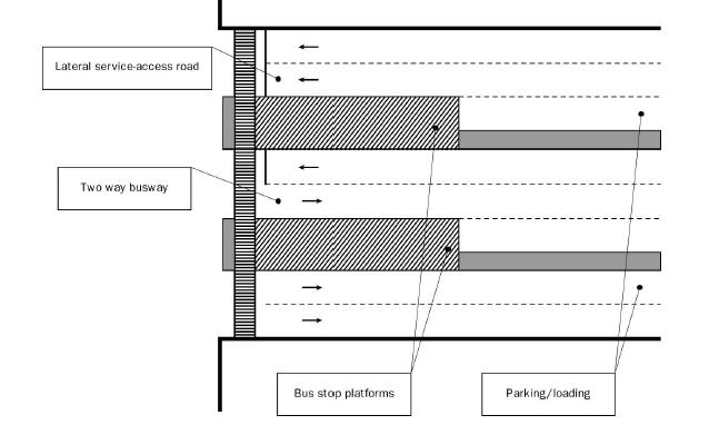
INTER – CITY BUS TERMINAL AT BANEPA Aakash Bhochhibhoya 87
LOCATION
Figure 3-12 : Cross section of bus way and service roads
Figure 3-13 : Bus terminal to close proximity of building density
3.2. CASE STUDY 2 : GONGABU BUS PARK
3.2.1. GENERAL INFORMATION
Gongabu Bus Park is located in Gongabu, Kathmandu. It covers total land area of 161 ropanies i.e. 81906.7 sq. m. with ground coverage of 9.83% and remaining coverage is for parking and berth area. The station type is Inter and Intra bus routes (long and short route station). Here, the entrance is accessed from north side of ring road. The structure type of terminal building and other commercial complex is of R.C.C structures. Peak hour is from 10:00am to 4:00pm. The terminal is constructed during 1993 A.D. with the help of JAICA.
3.2.2. SURROUNDING CONTEXT
Gongabu bus terminal is situated in the north-east corner of the Kathmandu valley along the Bishnumati River. Being the major bus Station of the Kathmandu valley the architectural fabric of the surrounding has changed a lot in these two decades. With opportunities and facilities, the open free land before few decades now has been converted into the urban hassle. Different vendor shops seems to disrupt the flow of the peoples and cause their disorientation, which now is the main reason for the mess of the people in and around the terminal complex.
Ring road in north side limits the boundary of the terminal complex whereas Bishnumati River flows along the west side of the site. The other sides of the terminal complex are surrounded by lodges, restaurants, retails and other commercial units.
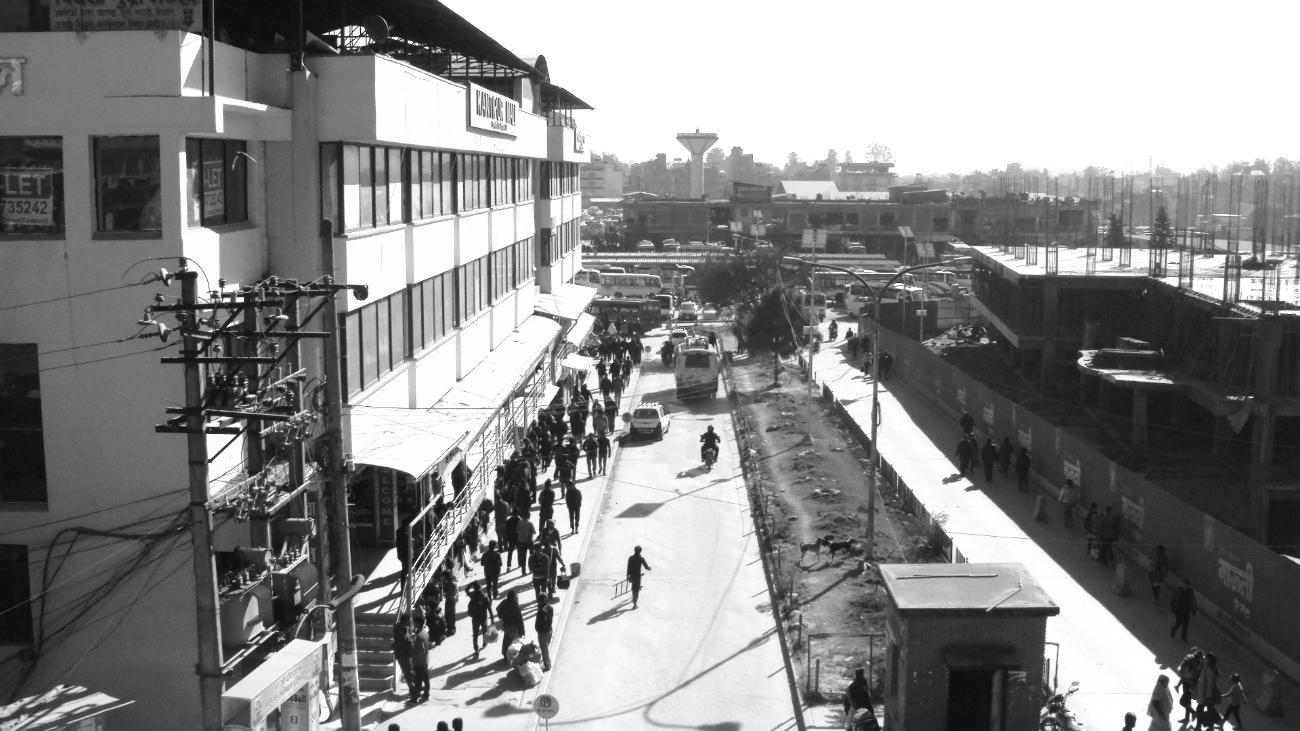
INTER – CITY BUS TERMINAL AT BANEPA Aakash Bhochhibhoya 88
Figure 3-14 : View from entrance, Gongabu bus terminal
3.2.3. HISTORICAL BACKGROUND
Gongabu bus terminal is one of the purposely designed bus terminal of the Kathmandu valley. The Gongabu bus terminal was constructed in 1993 AD with the help of Japanese government (technical team of JAICA). Initially Japanese design technical team JAICA in 1989 surveyed the site and in the end of the year came up with the design proposal, with the capacity of acquiring about 400 buses and other facilities for incoming and outgoing purposes. In July 1992, the construction of the terminal started. The project was completed in Feb 1993 and then handed over to the ministry of local development (MLD). In the same year the project was again handed to Kathmandu Metropolitan City (KMC). This bus terminal was serving to the people up to 2000 AD under the supervision of the KMC. Then in 2000 AD, KMC again handed over the terminal complex to the private company, Lotse Multipurpose Pvt. Ltd. with an agreement for 45 year under concession contract. Afterward the management of existing terminal complex and its extension work are undergoing under the supervision of this private firm.
3.2.4. IMPACT
The Gongabu and areas nearby are developing and urbanizing so that the proper planning guidelines and programs will better to develop systematic and scientific way of urban development. The life style, living pattern, occupation and modern need changes the quality of space and total urban landscape of the areas. The existing bus park is not too large but the extension program of this bus park is continuing and after 10-15 years the traffic volume of buses will create the noise and smoke problem in and around the bus park areas. The proper protection against these environmental problems should be solved in near future. The existing situation doesn‘t have such impact to the people and the environment.
3.2.5. SICIO-ECONOMIC ASPECTS
After constructing the bus terminal at Gongabu, the area nearby such as Balaju, Banasthali, Samakhusi along the Ring Road and the Gongabu area itself are developing rapidly. The land value is increasing more and more due to the migration of people from other parts of the city to capture the commercial activities. The Balaju area, very near to terminal, was already developed up to certain extent due to Balaju industrial state and other facilities. After developing Bus Park, the nodal point of Balaju along Ring Road, many commercial activities such as medical care, shopping complex, cinema hall, factories, and motor spares shops were developed. Market is developed linearly along the ring road towards the Gongabu bus park. The development trend will join the Gongabu just few years. Constructing 3-4 storied building develops the peripheral area of the bus park. The area is developing very faster with the facilities of rental spaces as well as private residential housing. The life style of the people at Gongabu is changed now a day and they are busy in the business instead of farming. Most of houses have indoor water supply, electricity, sewerage
INTER – CITY BUS TERMINAL AT BANEPA Aakash Bhochhibhoya 89
systems and other modern facilities such as road, telecommunication and cable lines and internet facilities. The public space, courtyard turned into bus stops or highly developed and busy place. The living standards of the people are increasing rapidly. The nodal junctions are developed as informal market places, which provide daily utensils, vegetable market, meat shop, tea stall, vendors, etc. the changing life style and occupation due to new development increased the economic status of the people of Gongabu and nearby areas.
3.2.6. ECONOMIC ACTIVITIES INSIDE BUS PARK
Kantipur mall and Retail shops inside the terminal complex is the main part that roofs the commercial events. Kantipur mall is located in the northern corner of the terminal complex beside the entry. The building is 4 storied and caters all types of shops. Also, retail shops inside a terminal building are present in the terminal complex which lies centrally of the site. The competition between these two commercial zones seems interesting and is also a reason for the public mess in and around the terminal complex.
The haphazard shops and stalls; vendors seem to disorient the public mass which is also the cause of the obstruction and mess around the terminal complex. But what is the reason that the vendors still exist and is sustainable in comparison to the complex is the interesting subject to discuss. During the case study it was seen that most of the people prefer the retail shops and vendors in comparison to the Kantipur mall. During the inspection the reasons for the preference came out to be;
Possibility of bargaining
Cheap in price (quality not being the first consideration)
Ground floor
Whereas some people preferred the Kantipur mall due to the following reasons;
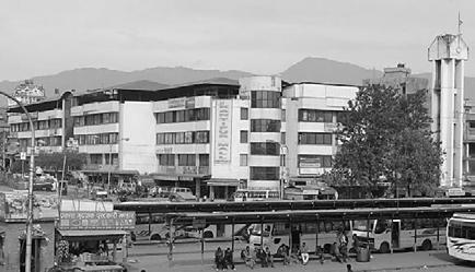
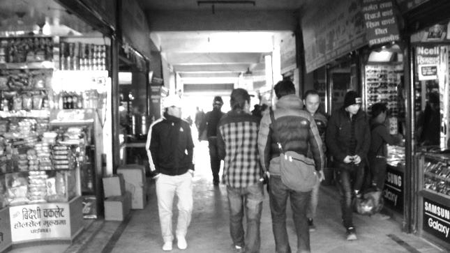
Less mess of people
Easy shopping
Near to entry
INTER – CITY BUS TERMINAL AT BANEPA Aakash Bhochhibhoya 90
COMMERCIAL COMPLEX AND RETAIL SHOPS
Figure 3-15 : Retail shops and Kantipur mall
3.2.7. ECONOMIC ACTIVITES OUTSIDE BUS PARK
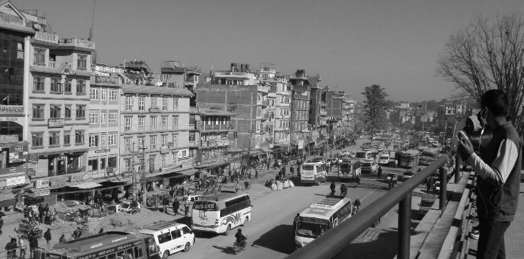
The Gongabu bus park is surrounded by the mess of commercial activities. There are numerous lodges, restaurants, fast food café, tea stalls, retails, hotels etc. around the bus park periphery. From private taxies to the dry food seller, all these activities are the happenings of the Gongabu bus park, had it not been there, there would not have been such commercial mess around the Gongabu area.
3.2.8. SOCIO-CULTURAL VALUE
The Gongabu bus park has not only been the place for the commercial activities but also provides space for the social interactions. Almost people from all parts of the country transport through the Gongabu bus park. Peoples seem to be interacting in the spaces such as food stalls and waiting spaces. Whether it may be the country‘s political talks, television serials talks, or business talks, the interactions between the people fills the life in the bus park periphery. Also the mass of people in the haat bazaar, bargaining and fixing the prices, people discussing in the political issues with a sip of tea in tea stalls, and taking about country‘s present situation with a newspaper in hand makes the environment of the bus park colorful. Had it been some green parks inside the bus park periphery would be like smell in gold. But most of the people seek some proper management of the bus park. Congested ticketing and waiting, haphazard shop stalls, unavailability of dust bins etc. seems to be the major problems of the Gongabu bus park. The new extension of the bus park may fulfill these issues. But regarding the communication and information‘s issues the bus park again lags a lot behind.
3.2.9. ARCHITECTURAL EXPRESSION
The terminal building, designed and constructed by technical team of JAICA expressed the modern language of art and architecture of that time. Combination of new materials such as glass, steel, concrete is incorporated to the traditional exposed brick facing wall, which is much common in present context. Also due to the new materials and technology, the types of space, shape, scope and many possibilities of architecture is introduced. The design of water tower is expressed to treat architecture as form of art and this dynamic form acts as uniqueness and as landmark of this bus park. But the architectural identity of the bus terminal seems to be dominated by the tall buildings in the boundary and also by the Kantipur mall inside the bus park periphery.
INTER – CITY BUS TERMINAL AT BANEPA Aakash Bhochhibhoya 91
Figure 3-16 : Activities outside bus park
3.2.10. PLANNING AND CIRCULATION
3.2.11. AREA/CAPACITY
The total area of Gongabu bus terminal is 161 ropanies. The Gongabu bus park extension project is designed to accommodate 700 buses / day. The idle bus parking is provided for 425 vehicles. Similarly it has 20 numbers of long route arrival berths and 41 numbers of long route departing berths. 43 berths are provided for local routes. Similarly 30 numbers of cars, 15 nos. of taxi, and 50 nos. of motor bikes could be parked in Gongabu Bus Park at a time. The bus terminal has flow rate of average 50 buses / hour during peak hour.
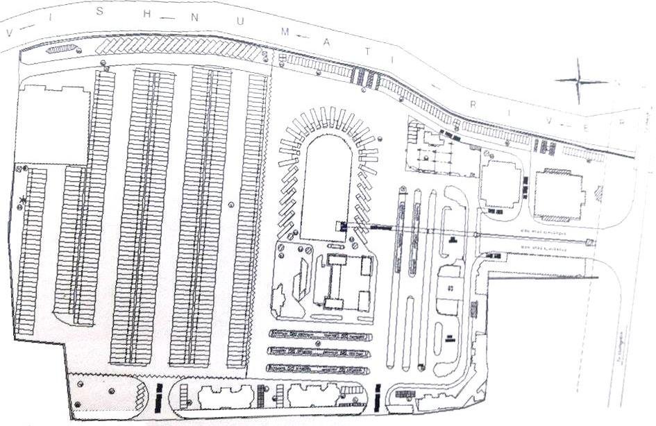
3.2.12. BUS TERMINAL AND ITS DIFFERENT UNITS
Before handing over the terminal complex to the Lotse Multipurpose Pvt. Ltd, there was no selfincome generating source. So for the sustainability, the company came with plan of giving contract to the private firm, commercial complex and small shops, restaurants, fast food café, mineral water shops and tea stalls in rent. These sectors surely are the source for the sustainability and resource generation. But, the slump due to the temporary structures made for income generation resource is in haphazard manner, and are the major reason for the disorientation of the public mess and
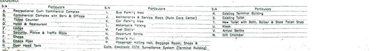
INTER – CITY BUS TERMINAL AT BANEPA Aakash Bhochhibhoya 92
Figure 3-17 : Master of Gongabu bus terminal; Refer annex
congestion. The Gongabu bus terminal is not only the source of revenue but it has also created many employment opportunities inside and outside the bus park.
3.2.13. ACCESS
The access to the site is from the north side of the terminal through the Ring road. Both entry and exit of the terminal is from the same side, which some time causes the overcrowding in the ring road during rush hours due to the movements of fast and slow moving traffic through same road.
3.2.14. TERMINAL BUILDING
The terminal building is located in the center of the complex which makes it easily accessible from all parts of the terminal complex. The terminal is a single storied building divided into two parts. The front part is ticket counter and waiting space covered by a truss structure. The other functions placed in the terminal buildings are; first aid room, information desks, PCO, audio video center, prepaid taxi, money exchange, police in charge office, ticket office, office canteen, and rest room for staffs. Dimensions of few parts: Ticket counter: 4‘x4‘
Waiting: 60‘x40‘+2x16‘x20‘
Office and reception: 1500sq ft.
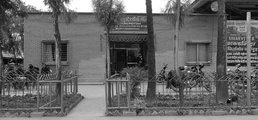
First aid: 9‘x10‘
3.2.15. TERMINAL MANAGEMENT OFFICE
The terminal management office is in east corner of the main terminal building. In 2000 AD, the Gongabu bus terminal was handed over to the private ownership Lotse Multipurpose Pvt. Ltd as contract basis up to 45 years. Afterwards the Lotse Multipurpose Pvt. Ltd. looks after the management of existing terminal complex, its extension work and all the problems regarding the passengers and other facilities issues. Also the different private bodies (companies) are appointed to different units of the terminal complex in lease contract basis for the management and daily functions. But the one who looks after the management of all these bodies is Lotse Multipurpose Pvt. Ltd.
INTER – CITY BUS TERMINAL AT BANEPA Aakash Bhochhibhoya 93
Figure 3-18 : Terminal management office
3.2.16. SECURITY
The new extension of the terminal complex also comprises of the traffic block, Metropolitan Police block and other Security units. But the conditions of these blocks are in merciful condition, but according to the information‘s from the authorities, the new extension of the terminal complex also plans a permanent building for these bodies which we can see in the new extension master plan of the terminal complex. Also 21 security guards are in charged by the company itself for additional security. These three bodies are the responsible authorities regarding the security issues of the terminal complex.
3.2.17. INFORMATION AND COMMUNICATIONS
No telephone booths are seen in the complex, also other means of communication such as internet café (cyber) are absent in the terminal complex. The audio and display medium for the passenger and route information‘s and buses time table is also unavailable which shows that the Gongabu bus terminal is lagging behind in case of information and communication. Also other information bodies like information desk also don‘t seem to function well.
3.2.18. TOILETS
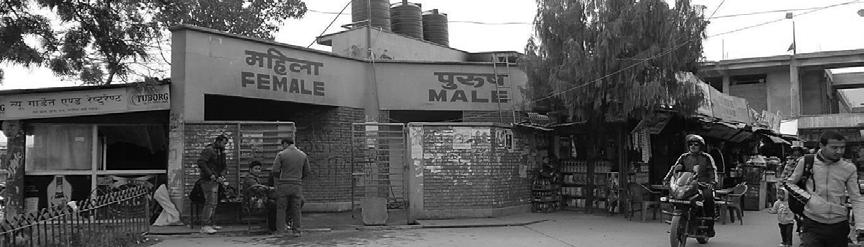
The toilets for both male and female are provided on the back side of the terminal building. In the male toilet block, 9 toilets for defecating and one Bathroom with 20 urinal units are provided. The common concrete large elongated concrete wash basin is provided for washing purposes. In the female toilet block, 9 toilets with wash basin are provided. The toilets are payable, Rs. 5/- for urinal and Rs.15/- for defecation use.
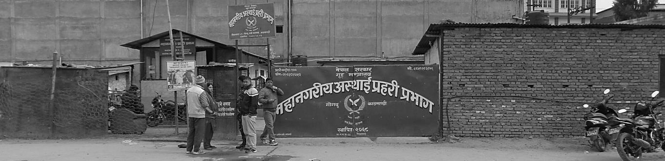
INTER – CITY BUS TERMINAL AT BANEPA Aakash Bhochhibhoya 94
Figure 3-19 : Metropolitan police office
Figure 3-20 : Public toilet block
3.2.19. WATER SUPPLY
The water supply is fulfilled through the tank tower with capacity of 225000 liters, designed in the south-west corner of the complex beside the Automobile care center. The tower stands as the landmark in the terminal complex due to its unique presence. Just near the tower, electric motor and water pump building is planned to lift up the water in the tank. The water is first collected in the tank by the process of boring with the help of electric motors. Then, the water is supplied to the rest of the complex units with the help of the water tank vehicles.
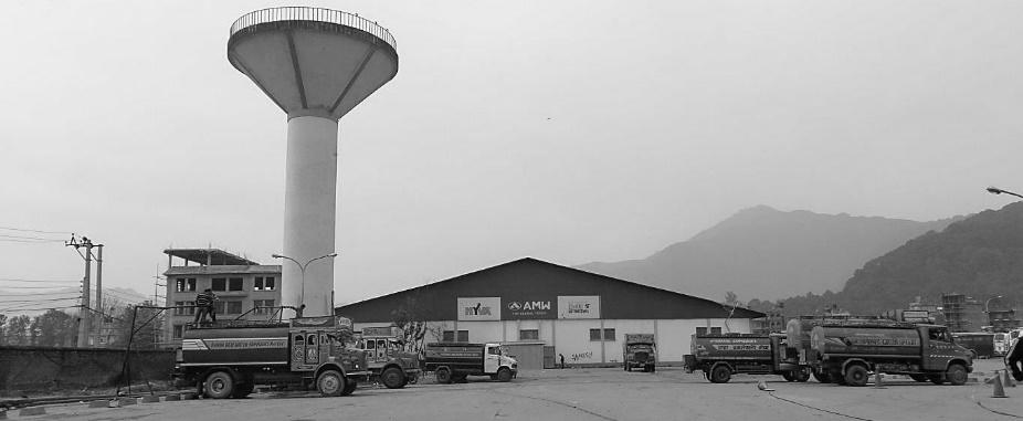
3.2.20. WAITING AREA
No such separate area is provided for waiting space or lounge. The open space between the main terminal building and two front blocks is used for ticketing facilities and at a same time used as a waiting space too. Therefore, the mess of people seems to be maximum in this particular area. Some sitting space is provided in the departure berth, which seems to be functioning well but the no of such seats are not enough according to the present context. Also a smoke from the vehicles departing is another problem that the person could feel during resting.
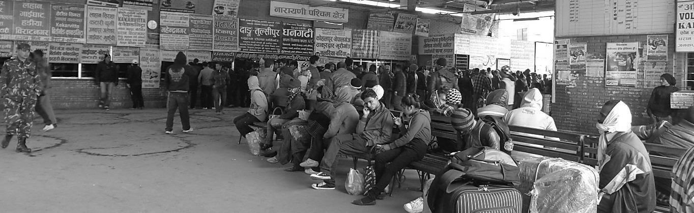
INTER – CITY BUS TERMINAL AT BANEPA Aakash Bhochhibhoya 95
Figure 3-21 : Overhead water tank
Figure 3-22 : Waiting area
3.2.21. TICKETING
The long route main ticketing counters are located in the front of the main terminal building. The spaces for ticketing counter are insufficient and also are confusing to new peoples. The new extension of the terminal complex also comprises of the new ticketing building which now is in construction phase.
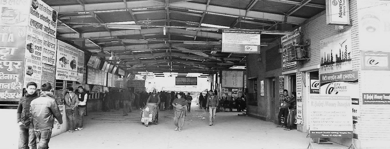
3.2.22. UNDER CONSTRUCTION
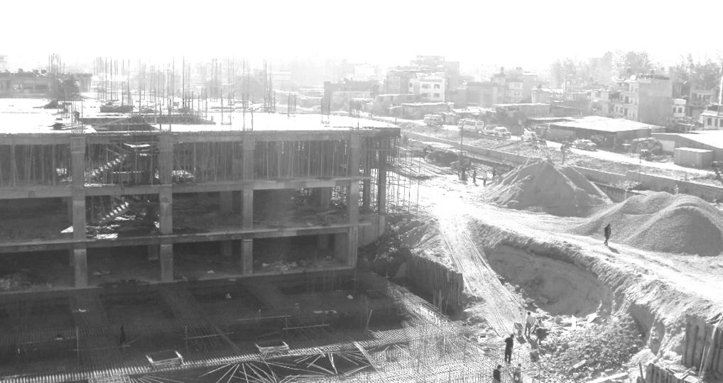
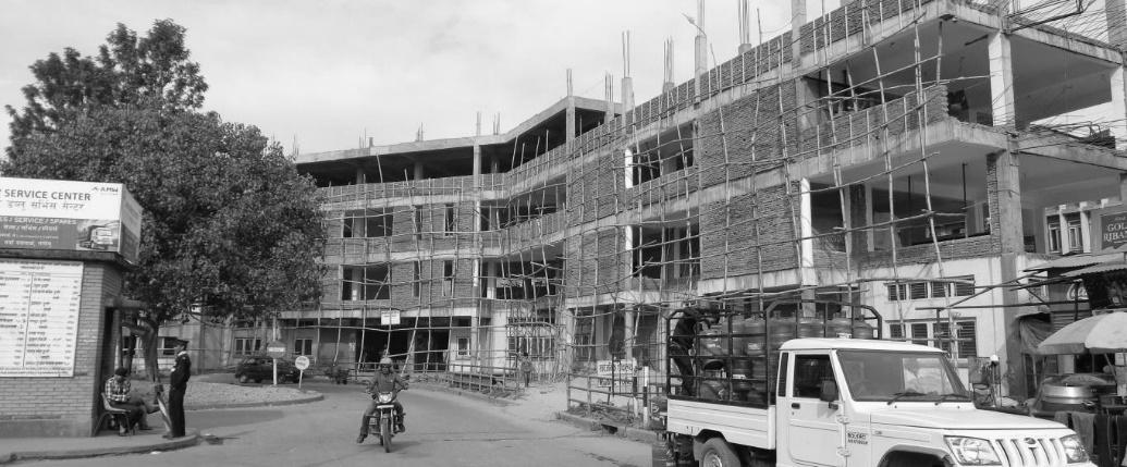
INTER – CITY BUS TERMINAL AT BANEPA Aakash Bhochhibhoya 96
Figure 3-23 : Ticket counters
Figure 3-24 : Under construction Terminal Building
Figure 3-25 : Under construction Mall
3.2.23. OTHER FACILITIES
3.2.23.1. WASTE MANAGEMENT
A large container is provided by the municipality for solid waste. After container fills, the container is then taken away by the municipality for the further management and dumping purposes. Waste water from the complex sewer lines are laid out in certain intervals to the city sewer line. (Two sewer elongated east-west and the storm, sewage and other liquid wastage.)
3.2.23.2. COOLIE
20 coolies in total are available in the terminal for loading and unloading purposes. These coolies are not hired by the company and seem to continuing the work from long time.
3.2.23.3. HYGIENE
Total 20 persons are employed by the company in order to maintain the hygiene in the terminal complex. There is a change in a shift twice a day between the workers. But there are no dustbins seen outside the building, which adds load to the workers working for the maintenance and cleanliness of the bus terminal.
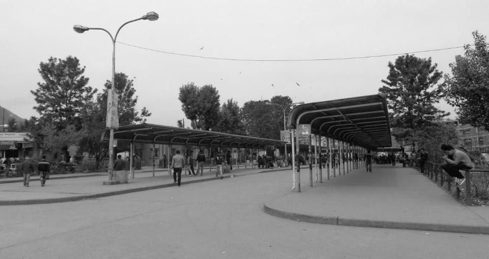
3.2.23.4. LIGHTING
The halogen lamps are erected on the parking and lane areas and fluorescent lamps are used in the terminal building and departing berth. About 30 halogen lamp poles are placed in different places in the bus park. The control room/electric board is designed in the main terminal building. The alternative source of energy seems to be absent except generator in some part of the terminal complex.
3.2.24. ARRIVAL BERTH
INTER – CITY BUS TERMINAL AT BANEPA Aakash Bhochhibhoya 97
Figure 3-26 : Arrival berth
Arrival berth is located on the east side of the terminal building. There are two lanes (6.5m each) with traffic separator and one lane (5m width) provided to bypass the long route bus directly to the long route parking area. The half of the land in arrival side is placed as green space, perhaps for the future expansion of the lane. No sitting space are provided in the arrival berth in a concept that, people who came from out of place don‘t want to spend their time in bus park. But a sitting space seems to require for people waiting for welcoming the coming persons. The truss structure is provided as the shades.
3.2.25. DEPARTURE BERTH
The departure berth is located around the terminal building with radial maneuver of the bus bays. The station goes radial at the turning with an angle of 12 degrees with one another and 41 degrees at the linear position. It can hold 29 buses at a time and is covered with a steel roof so that people can wait for buses. But if seen practically the north side of the departure berth only seems to be functioning more as it is near to the exit lane.
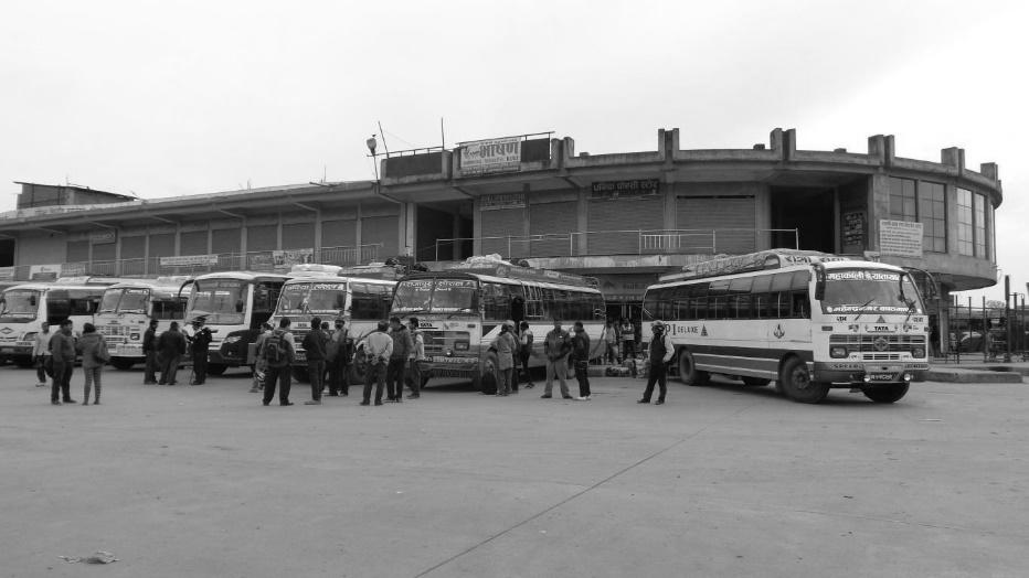
3.2.26. LONG TERM PARKING LOT
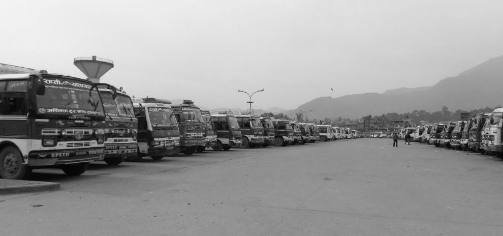
INTER – CITY BUS TERMINAL AT BANEPA Aakash Bhochhibhoya 98
Figure 3-27 : Departure berth
Figure 3-28 : Long term parking lot
3.2.27. AUTOMOBILE CARE CENTRE (AMC)
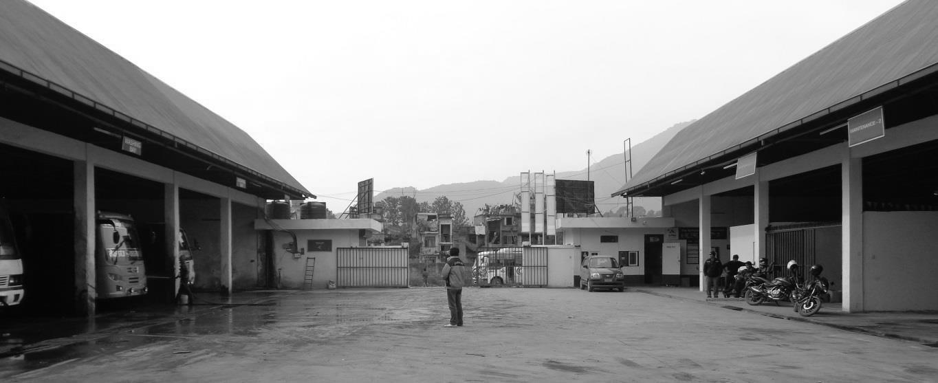
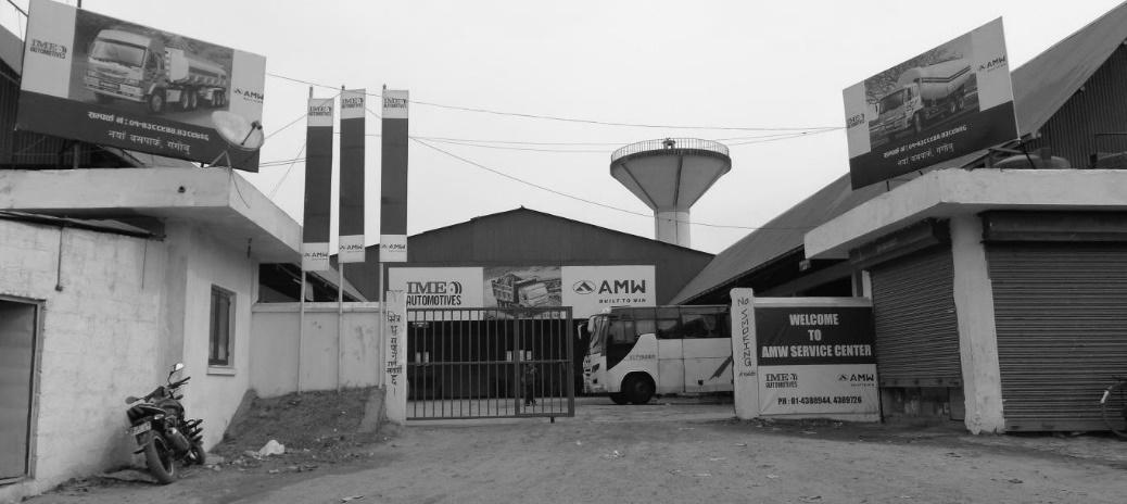
The automobile care Centre is located in the South-West corner of the terminal complex. The automobile care Centre consists of the different units they are; denting painting unit, resoling unit, and maintenance and washing unit. The denting-painting and resoling unit lies on the outward side of the automobile care center in the western part.
The maintenance and washing unit is planned inside the Automobile care center. There are 4 bays for general maintenance, 1 free service bay and 2 lifting bays in the maintenance units. But the mechanic during conversation said that about 20 numbers of buses are repaired at once in the area. He said that, the Japanese planned the area for long foreign buses which is in appropriate for buses in Nepal. Therefore, 20 buses could be catered at once. The washing unit consists of 4 bays. 1 bay is planned for the generator facility. Also the automobile care center consists of 1 spare shop, 1 store, and staff quarter and managers room.
INTER – CITY BUS TERMINAL AT BANEPA Aakash Bhochhibhoya 99
Figure 3-29 : Automobile Care Centre
Figure 3-30 : Washing bays (left) & maintenance bays (right)
3.2.28. LISTS OF ROUTES PROVIDED
INTER – CITY BUS TERMINAL AT BANEPA Aakash Bhochhibhoya 100
S.No Name of route Distance km Directi on 1 KTM - Narayangad - Hetauda 220 East 2 KTM - Birjung 270 East 3 KTM - Kalaiya 284 East 4 KTM - Barhathawa 323 East 5 KTM - Gaur 329 East 6 KTM - Manlagaja 341 East 7 KTM - Sindhuli 361 East 8 KTM - Gausala - Mahottari 363 East 9 KTM - Janakpur 375 East 10 KTM - Raghunathpur - Dhanusa 385 East 11 KTM - Nagarain - jatahi 388 East 12 KTM - Jaleswor 391 East 13 KTM - Jaleswor - Jangharkhola 400 East 14 KTM - Matihani 400 East 15 KTM - Siraha 410 East 16 KTM - Katari 414 East 17 KTM - Bariyarpatti 430 East 18 KTM - Bhagwanpur 433 East 19 KTM - Gaighat 447 East 20 KTM - Rupani - Rajbiraj 450 East 21 KTM - Fattepur 475 East 22 KTM - Dharan 539 East 23 KTM - Rajbiraj - Hanumanagar - Biratnagar 540/01 East 24 KTM - Biratnagar 541 East 25 KTM - Biratnagar - Katahari 545 East 26 KTM - Letang - Morang 549 East 27 KTM - Urlabari - Durgapur 562 East 28 KTM - Madhumalla - Morang 573 East 29 KTM - Gauriganj 584 East 30 KTM - Sivhagunj 584 East 31 KTM - Birtabajar 595 East 32 KTM - Sanischare 600 East 33 KTM - Rajgadh 606 East 34 KTM - Budhbare 607 East 35 KTM - Goldhap (Jhapa) 608 East 36 KTM - Kakadvitta 610 East 37 KTM - Bhadrapur 610 East 38 KTM - Kumarkhoj (Jhapa) 615 East 39 KTM - Bahundadi 618 East 40 KTM - Dhulabari - Santinagar 622 East 41 KTM - Baniyani 625 East 42 KTM - Ilam 676 East 43 KTM - Dhadingbesi 87 West
Table 3-2 : Lists of the routes provided
INTER – CITY BUS TERMINAL AT BANEPA Aakash Bhochhibhoya 101 KTM - Kurintar (Up to Manakamana Cable car) 99 West 45 KTM - Gorkha 141 West 46 KTM - Narayangad 146 West 47 KTM - Rampur (Chitwan) 156 West 48 KTM - Dume (Besi Sahar) 180 West 49 KTM - Pokhara 202 West 50 KTM - Syanjha 235/67 West 51 KTM - Butwal 259 West 52 KTM - Mahespur 259 West 53 KTM - Pokhara waling 265 West 54 KTM - Baglung 274 West 55 KTM - Bhairahawa 282 West 56 KTM - Bhairahawa - Lumbini - Taulihawa 328 West 57 KTM - Krishnanagar 349 West 58 KTM - Pokhara waling - Bhairahawa 386 West 59 KTM - Bhaluwang Puthan 425 West 60 KTM - Dhorahi - Tulsipur 434 West 61 KTM - Rolpa - Liwang 480/4 West 62 KTM - Nepalgunj 531 West 63 KTM - Pokhara Tanseng -Kapilbastu - Narayanghad one way 552 West 64 KTM - Gulariya 566 West 65 KTM - Chisapani Karnali 570 West 66 KTM - Kothiyaghat 591 West 67 KTM - Devsthal - sallibazar 597 West 68 KTM - Surkhet 600 West 69 KTM - Dhangadi 688 West 70 KTM - Mahendranagar 695 West 71 KTM - Atteria - Dadeldhura 773 West 72 KTM - Atteria - Silgadi 814 West 73 KTM - Atteria - Dadeldhura - Baitadi 864 West 74 KTM - Dhangadi - Sitagadi - Sanfebagar 899/6 West 75 KTM - Galchi 47/18 North 76 KTM - Trisuli 69 North 77 KTM - Devighat Trisuli 72 North 78 KTM - Dhunche 117 North Dir. No of routes % 1 East 42 53.85 2 West 32 41.02 3 North 4 5.13
3.2.29. ANALYSIS
NEED
The terminal building is not easily accessible for physically challenged people. Smooth in vehicular planning but conflict with pedestrian paths. Areas are separated but connection between units are unmanaged. Impractical layout of departure bay. Inadequate waiting spaces; canopies not enough. During summer season, double height of waiting spaces with open plan provide cool and comfort environment but not during rainy and winter seasons. Lack of visibility to all places directly made the passengers and drivers confuse.
SIZE
Total land area of 161 ropanies i.e. 81906.7 sq. m. with ground coverage of 9.83% and remaining coverage is for parking and berth area is optimum but lacks green spaces for passengers. Narrow entry point resulted in difficult in vehicular movement during peak hour & overloaded in ring road.
LOCATION
Bus terminal is located side by ring road and nearby densely populated areas. In some point, nearby residence is getting disturbed due to noise and air pollution produced by vehicles. It formed a component in the hierarchy of transport systems. It is located in minimum impact area. The concentration and dispersal cost is minimum. It is located such that as point of coordination and integration between intercity and intra-city transport.
DESIGN
It is not well designed and also doesn’t segregate the bus and non-bus traffic. Segregation of pedestrian and vehicular movement is also maintained. Unmanaged system resulted in vehicular traffic conflict. Minimum processing for buses route to the terminal is maintained by locating bus terminal in major route access (ring road).
Way finding and signage problem. Waste management in parking and lack of dustbins in whole bus terminal area. Improper lighting system during night time.
INTER – CITY BUS TERMINAL AT BANEPA Aakash Bhochhibhoya 102
3.3. CASE STUDY 3 : BHARATPUR BUS TERMINAL, BHARATPUR
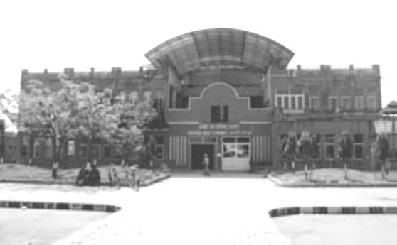
3.3.1. GENERAL INFORMATION
Station Type: Long Route
Location: Bharatpur, Chitwan
Total Land Area: 66-0-0-0
Entry: Mahendra Highway
Temporary Owner: Kendriya Bus Terminal
3.3.2. PLANNING AND CIRCULATION
It is located at quite a distance from the highway. This bus terminal has less impact to the highway. This bus terminal has less impact to the traffic of the highway. The circulation of the buses are clockwise. The main terminal building is located at the fort of the main entry of the terminal. Separate entry and exit of buses inside the terminal. Arrival and departure berth (Capacity- 15 each), is located at the backside of the terminal building. Separate parking spaces are provided for long route buses and private vehicles. Long term parking of 200 lots of each (3 X 12.8 sq. M) With 11 m separator.
3.3.3. TERMINAL BUILDING
It is located quite close to entrance. 2.5 floor structure which is designed with climatic response. The Ground floor is for waiting lounge (Capacity-130), ticket counters, medical room, drinking water, control room and kiosks. The first floor is for offices, conference and multipurpose hall.
3.3.4. ARRIVAL AND DEPARTURE BERTH
It is located at the back side of the terminal building. Roof is covered with steel trusses and CGI sheet. Open structure with canopy at ends of short side. Island planning for loading and unloading of buses. Saw tooth maneuver and waiting space, which is placed at middle.
INTER – CITY BUS TERMINAL AT BANEPA Aakash Bhochhibhoya 103
Figure 3-31 : View from entrance, Bharatpur bus park
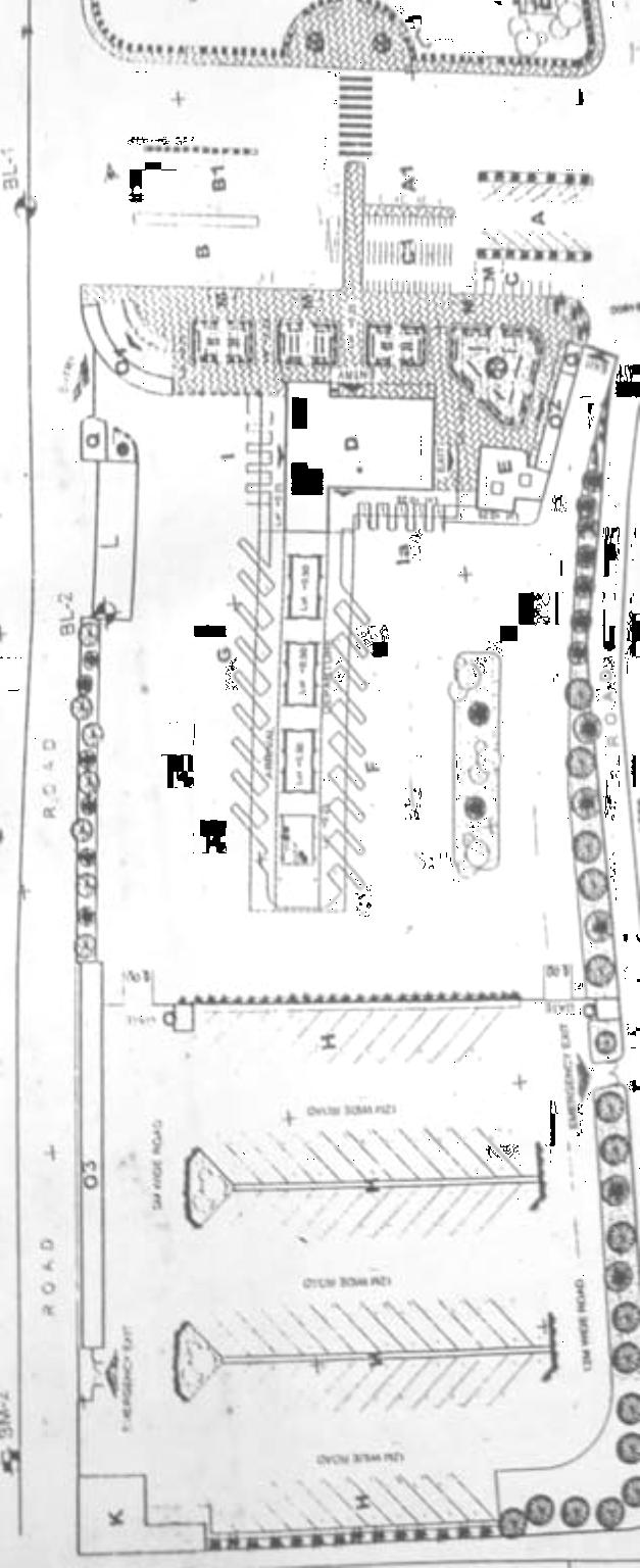
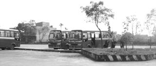
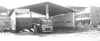
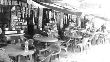


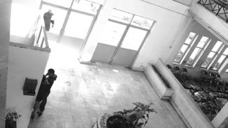
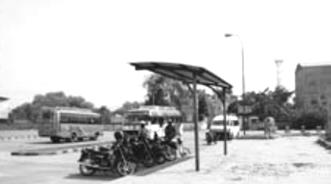
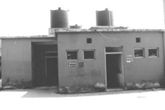
INTER – CITY BUS TERMINAL AT BANEPA Aakash Bhochhibhoya 104
Figure 3-36 : Long term parking
Figure 3-37 : Auto-workshop
ENTRY EXIT EXIT EXIT
Figure 3-38 : Master plan of Bharatpur bus terminal
Figure 3-32 : Eatery
Figure 3-33 : Waiting space
Figure 3-34 : Public toilet
Figure 3-35 : Arrival berth
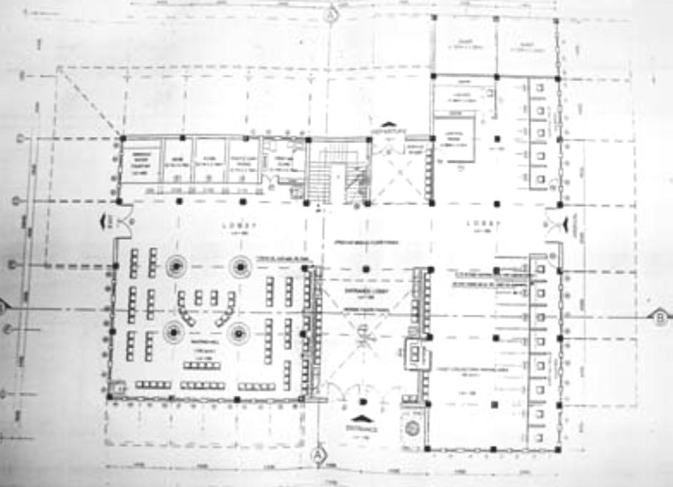
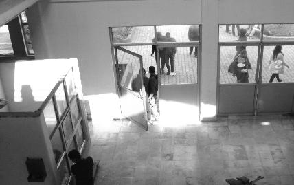
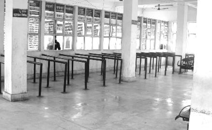
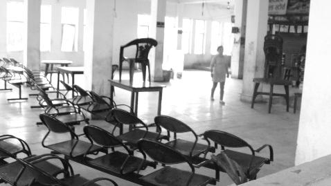
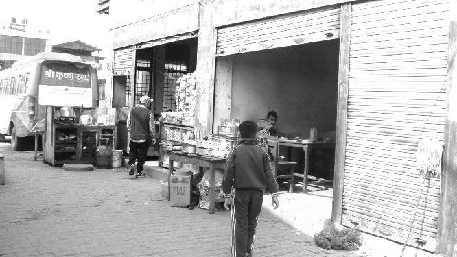
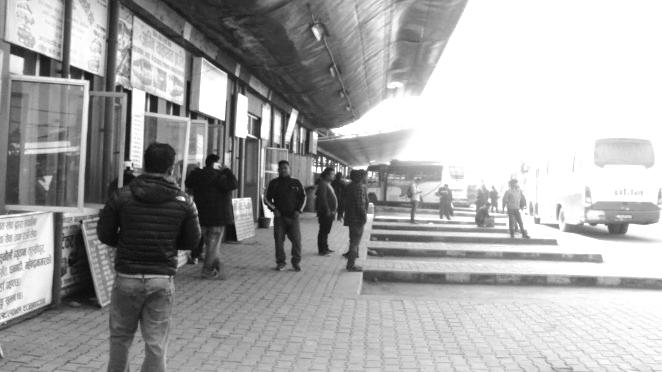
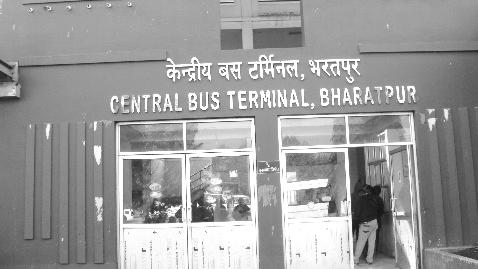
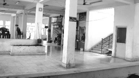
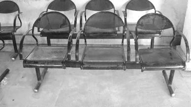
INTER – CITY BUS TERMINAL AT BANEPA Aakash Bhochhibhoya 105
Figure 3-41 : Ground floor plan, terminal building
Figure 3-39 : Kiosks
Figure 3-40 : Shades outside ticket counter
Figure 3-46 : Waiting area
Figure 3-45 : Lobby
Figure 3-44 : Ticket counter
Figure 3-43 : Entrance door
Figure 3-42 : Clock and display board
PARKING
Bharatpur Bus Terminal has both long route and short route parking space.
Long Route Parking
It is located at the back side of Bus Terminal. It has the total capacity of 200 buses and 40 micro buses. Each bus has given the parking area of (3 x 12.5) sq., with a separator road of 11 m in between.
Short Route Parking
For the private vehicles and motorcycles, is arranged at the front terminal building.
ROADS AND PEDESTRAIN
Black topped finishing is provided for entire road. RCC road pavement with grade separation for vehicle and pedestrian.
WATER SUPPLY AND SANITATION
Two deep tube wells with submersible pumps and overhead water tank of 225000 liters capacity provide a regular water supply. The overhead water tank with the clock acts as the landmark. For the proper management of waste water. Reed bed system is available. It is located at the river bank. The other cleaning is done by hand picking and sweeping.
TOILETS + SHOWER
It is located at the right side of the terminal building. Shower room and toiled are combined. There is provision of separate toilet for disable people.
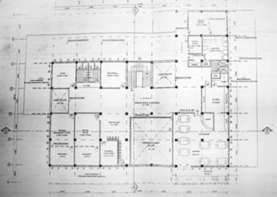
INTER – CITY BUS TERMINAL AT BANEPA Aakash Bhochhibhoya 106
Figure 3-47 : First floor plan 3.3.5. INFRASTRUCTURE AND SEREVICES
LIGHTING FACILITY


Halogen lamps are provided to the parking and roads. Fluorescent lamps are provided inside the terminal building.
AUTO
WORKSHOP
It is located at the backside of the terminal. It consists of maintenance section, Welding and Dent repair. Total capacity of workshop is only for 2 buses.
3.3.6. DESIGN ELEMENT AND STRUCTURE
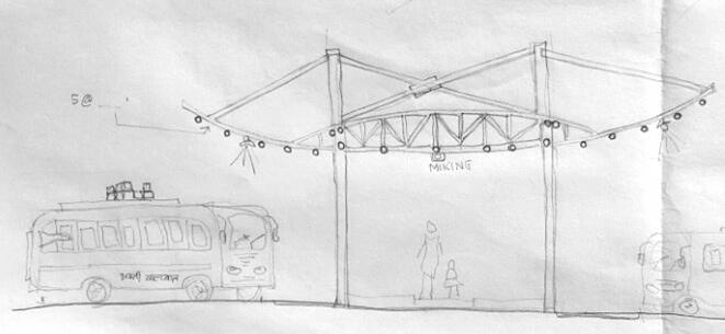
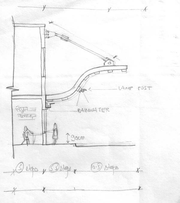
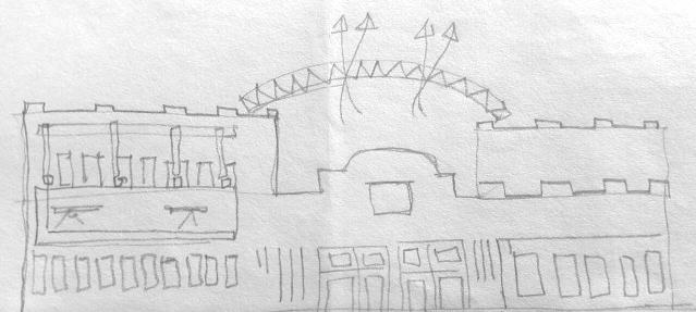
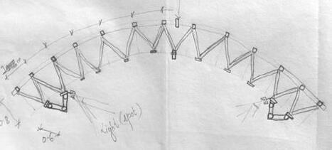
3.3.7. ANALYSIS
The terminal is well planned with separate entry and exit of buses.
Enough parking spaces for both long term and short term parking.
Retail shops are available near entry.
Although the terminal is well planned, its located is at quite distance from highway.
Solid waste is not properly managed.
INTER – CITY BUS TERMINAL AT BANEPA Aakash Bhochhibhoya 107
Figure 3-49 : Double storey open semi open lobby
8 m 4 10 m 7 m
Figure 3-48 : Bow string truss above lobby
Figure 3-50 : Steel structure outside ticket counter as shading device
Figure 3-51 : Long span steel structure in long route departure berth
3.4. CASE STUDY 4 : GSRTC BUS PORT, GEETA MANDIR, AHMENDABAD
3.4.1. GENERAL INFORMATION
Gujarat State Road Transport Corporation (GSRTC) is a state owned and operated passenger transport organization – a State Transport Undertaking (STU) – providing bus services both within Gujarat and neighboring states. GSRTC came into existence on 1st May, 1960 on formation of Gujarat, as an off-shoot of Bombay State Road Transport Corporation, with a purpose of providing an efficient road transport facility to the people of Gujarat state. From a modest beginning of 7 divisions, 76 depots and a fleet of 1,767 buses; within a span of more than 52 years by now, as on date, it has gone to 15 Divisions, 125 Depots, 226 Bus Stations, 1554 Pick-up Stands and a fleet of over 8,000 buses.
One of the best GSRTC bus terminal is Geeta Mandir bus port which is located in Geeta Mandir, Ahmendabad, India. Total land area covered is 32,534 sq. m. including 3 commercial blocks (South block only) where the built up area is 79,552.62 sq. m. Bus Terminal facility covers area of 18,200 sq. m, residential = 15200 sq. m, hotel/ serviced apartments = 10700 sq. m, commercial = 9200 sq. m, retail shops = 55200 sq. m.
The terminal is Inter and Intra bus routes (long and short route station). Scope: Mixed use development, including BTF, residential, hotel/services apartments, commercial and retail. Entry is of 12 m wide road from Geeta Mandir Road. Structure type is R.C.C structures. The bus port was inaugurated in 6 August, 2015 by Chief Minister Anandiben Patel with Prime Minister Narendra Modi. The Architect of the bus port are (GSRTC) and Hub Town jointly developed with leadership Team: Stephen Jones, Boris Manzewski in PPP (Public Private Partnership) Model.
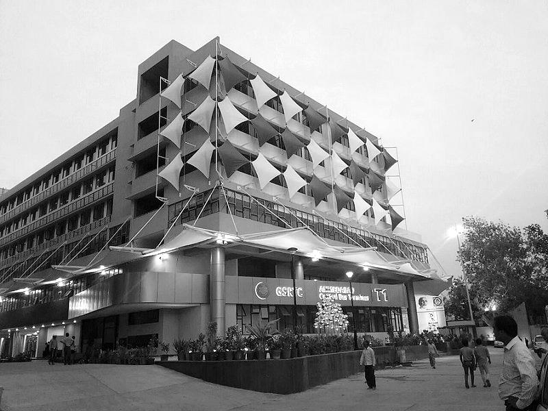
INTER – CITY BUS TERMINAL AT BANEPA Aakash Bhochhibhoya 108
Figure 3-52 : View from entrance, Geeta Mandir bus port, Ahmendabad
3.4.2. SURROUNDING CONTEXT
The city of Ahmedabad was founded in 1411 AD as a walled city on the eastern bank of the river Sabarmati, now the seventh largest metropolis in India and the largest in the state. The urban agglomeration (UA) population has increased from 3.31 Million in 1991 to 4.5 Million in 2001.
Ahmedabad is the commercial capital of the state. Known as the textile capital of India, it is also a major industrial and financial city contributing about 14% of the total investments in all stock exchanges in India and 60% of the total productivity of the state 21. It lies in the cotton belt of Gujarat, 552 km north of Mumbai and 96 km from the Gulf of Cambay.
Ahmedabad has a tropical monsoon climate which is hot and dry, except in the rainy season. Summer days are very hot with mean maximum temperature of 41.30C while, nights are pleasant with mean minimum temperature of 26.30C. The mean maximum and minimum temperature in winter are 300C and 15.40C respectively. The average annual rainfall of the area is 782mm, although there is a considerable variation from year to year. It occurs generally during the months of June to September. The average relative humidity is 60% which ranges from 80% to 90% during rainy season.
Source: (GIDB/LB, 2000)
Demand for transportation is a derived demand. Population characteristics such as size, concentration, income, vehicle distribution, economy in terms of location of employment, education and entertainment activities etc., determine travel demand. 22
21 Reena Lazar, Increasing Resources to Local Government in Ahmedabad, India. Local Strategies for Accelerating Sustainability: Case Studies of Local Government Success. ICLEI Study, Canada, Ma (Lazar, 2002)y 2002
22 GSRTC(Gujarat state road transport corporation), Background of GSTRC,2015
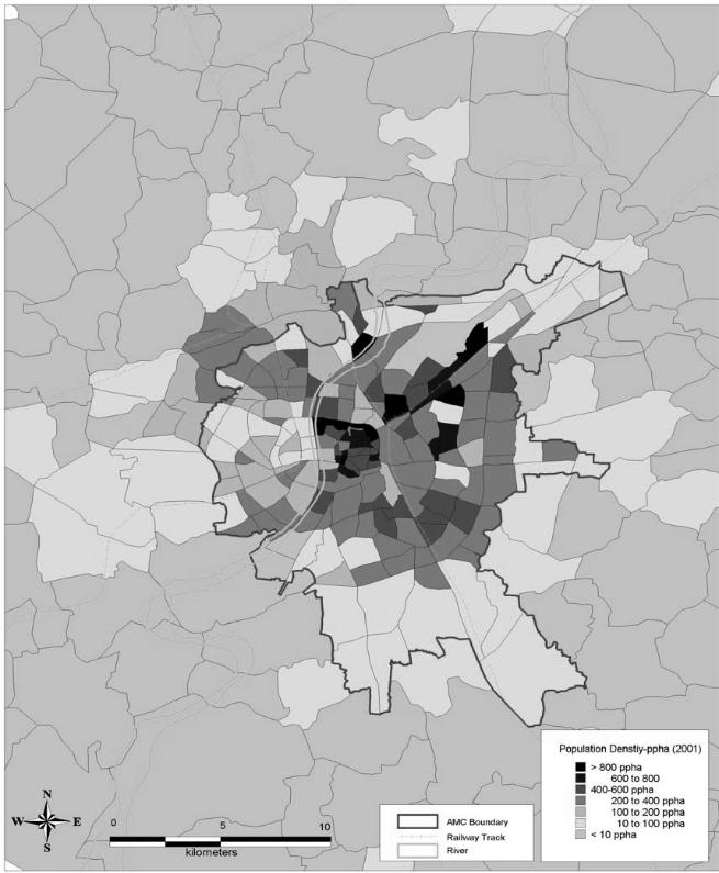
INTER – CITY BUS TERMINAL AT BANEPA Aakash Bhochhibhoya 109
Figure 3-53 : Population Density, Ahmedabad
3.4.3. HISTORICAL BACKGROUND


Geeta Mandir bus port is one the busiest bus port in Ahmedabad. The new bus port was inaugurated on 6th August, 2015 under a public-private partnership (PPP) project between Gujarat State Road and Transport Corporation and Hub town Limited.
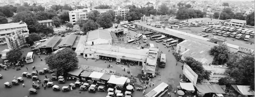
Old bus port
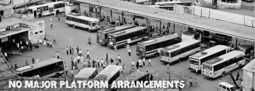
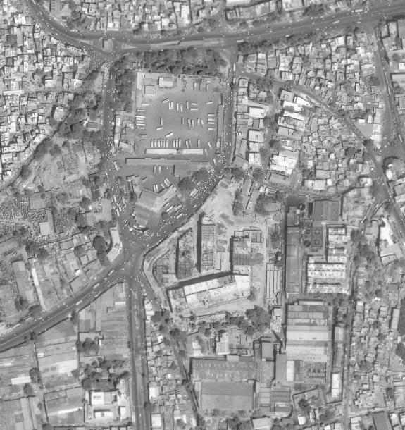
New bus port
Source: (SAS.PLANET, 2016)
Since the old bus port was unable to cater and provide enough facilities for staffs and passengers like: overcrowded buses, unorganized premises, no proper signage system, no major platform arrangements, no comfortable waiting areas, no rest rooms, no healthy drinking water facilities, no wash room arrangements, no cleanliness and no maintenance of the area and buses; new bus port was constructed nearby by the old one. 23
INTER – CITY BUS TERMINAL AT BANEPA Aakash Bhochhibhoya 110
23 Ltd., U. C. (2015). Changing Lives - New Face of bus travel experience in Gujarat @Geeta Mandir Bus port Ahmedabad. Retrieved from UNISON, Gujarat, INDIA. : http://www.unisoncom.com/
Figure 3-54 : Location of Old and New bus port
Figure 3-56 : Unmanaged platform arrangements on Old Geeta Mandir bus port
Figure 3-55 : Old Geeta Mandir bus port, Ahmedabad
3.4.4. IMPACT
Nearby Geeta Mandir bus port are developing and urbanizing so that the proper planning guidelines and programs will better to develop systematic and scientific way of urban development. The life style, living pattern, occupation and modern need changes the quality of space and total urban landscape of the areas. The new bus port is a connectivity between villages and urban areas. Due to the well planned and proper facilities, the number of commuters; including daily and business commuters, are increasing.
3.4.5. SOCIO-ECONOMIC CHARACTERISTICS
3.4.5.1. AGE WISE DISTRIBUTION OF POPULATION
As per the survey, 80% of the total population is in the active age groups. About 58% of the population are in the working age group years and another 29% in the age-group of students. About 8% of the population belongs to retired and old age category. (GIDB IPTS Study (2000) by LBA, 2000)
3.4.5.2. ACTIVITY STATUS
As presented in table below about one third of the persons are workers, about one fifth are learners who mainly contribute to two major purposes of travel; work and education. Of the 30 % workers dependency on private service or own business is in almost equal proportion (together 25-28%) with only about 4 percent engaged in government service.
Activity Status
Source: (GIDB IPTS Study (2000) by LBA, 2000)
Refer annex 8.9, for detail information of activity status of persons. The above table 3.2 doesn’t show all the occupation area.
INTER – CITY BUS TERMINAL AT BANEPA Aakash Bhochhibhoya 111
Area Occupation total govt. servi ce % a g e priva te servi ce % a g e busine ss % a g e unemploy ed % a g e stude nt % a g e hous ewife % a g e Othe rs % a g e % a g e Walle d city 8208 2 4719 9 1 3 55575 1 6 13307 4 70309 2 0 1133 27 3 2 4681 7 1 3 35474 3 1 0 0 Total 2521 91 4 6970 70 1 2 77366 0 1 3 261648 4 12249 05 2 1 1822 81 3 1 8995 09 1 5 59317 98 1 0 0
Table 3-3 : Distribution of Persons by
3.4.6. ECONOMIC ACTIVITIES
The Geeta Mandir Bus Port is surrounded by the mess of commercial activities, Banks and Textile industry. There are numerous lodges, restaurants, fast food café, tea stalls, retails, hotels etc. around the bus port periphery.
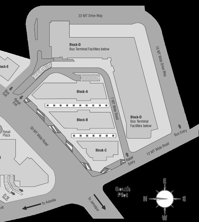
In Bus Port, ground, first and second floor is used by GSRTC and upper floor is used for commercial activities. 24
Similarly, the bus port is complimented with 3 well designed and well executed for commercial use. The 8 storey buildings accommodate 2,000 shops; small and large, and other markets. 25
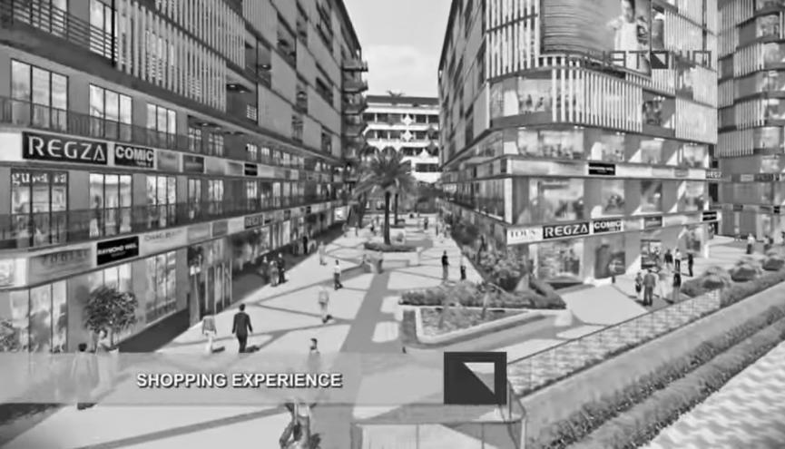
INTER – CITY BUS TERMINAL AT BANEPA Aakash Bhochhibhoya 112
24 "3-year-old abandoned at Geeta Mandir Bus Port". Times of India. Retrieved 11 May 2015. (India T. o., 2015) 25 Tube, Y. (2015). Geeta Mandir Bus Port, GSRTC. Retrieved from https://www.youtube.com/watch?v=YXyQ1Tw58Vs, viewed on Jan 15,2017 at 5:25 pm
Figure 3-57 : Commercial complexes; refer annex 8.10
Figure 3-58 : 3D view of commercial complex by Town Hub
3.4.7. SOCIO-CULTURAL VALUE
The Geeta Mandir Bus Port has not only been the place for the commercial activities but also provides space for the social interactions. Almost people from all parts of the state transport through the bus port. People seem to be interacting in the spaces such as food stalls and waiting spaces. Whether it may be the country‘s political talks, television serials talks, or business talks, the interactions between the people fills the life in the bus port periphery. (Tube, Tv9 Gujarati, 2015)
3.4.8. ARCHITECTURAL EXPRESSION
Geeta Mandir Bus Terminals is a unique adaptive reuse project – one of the first of its kind in India’s infrastructure sector – and includes the redevelopment of an existing bus terminal located in the heart of the Ahmedabad.
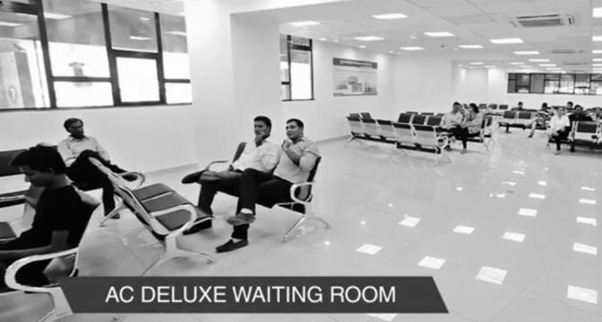
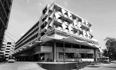
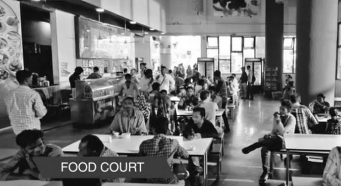
In close proximity to the historic Pol area (also called the old city), the development has two components: a bus terminal facility, and a mixed-use saleable area to be operated and maintained by Hub town Limited for a period of 30 years.
The form is inspired by the notion of constant movement. The facade design creates a strong horizontal expression, with continuous shadow lines holding the forms together and connecting to existing context, thus accentuating the idea of movement. (woodsbagot., 2017)
Geeta Mandir Bus Terminals is a transit-oriented development (TOD) under a public-private partnership (PPP) project between Gujarat State Road and Transport Corporation and Hub town Limited. 26
26 Woodsbagot... Retrieved from http://woodsbagot.stealthtraffic.com/project/geeta-mandir-bus-terminals-ahmedabad-india viewed on (2017, Jan 10)
INTER – CITY BUS TERMINAL AT BANEPA Aakash Bhochhibhoya 113
Figure 3-59 : Food court and waiting room as social interaction space
Figure 3-60 : Front facade
3.4.9. PLANNING AND CIRCULATION
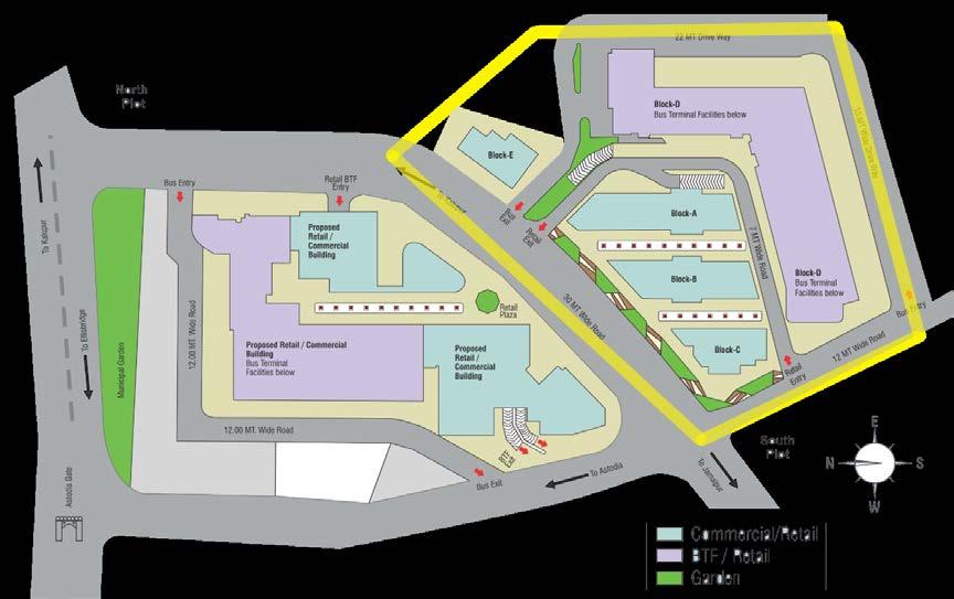
Source: (Town, 2015), Viewed: Jan 3, 2017, Focus on South Block only
Source: (Town, 2015), viewed: Jan 3, 2017, focus on South Block only;
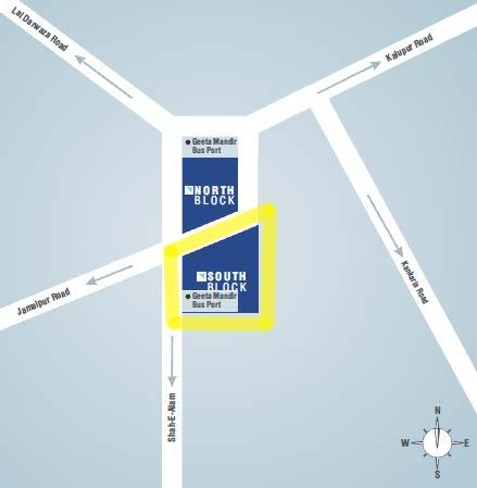
INTER – CITY BUS TERMINAL AT BANEPA Aakash Bhochhibhoya 114
Figure 3-61 : Location Key Plan
Figure 3-62 : Geeta Mandir Site Plan, Ahmedabad
3.4.10. AREA / CAPACITY
Location: Geeta Mandir, Ahmendabad, India
Total land area: 32,534 sq. m. including 3 commercial blocks; Block A,B,C (South block only)
Built up area: 79,552.62 sq. m.
Bus Terminal facility (BTF): 18,200 sq. m.
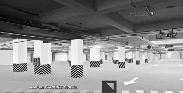
Residential = 15200 sq. m. and Hotel/ Serviced Apartments = 10700 sq. m.
Commercial = 9200 sq. m. and Retail = 55200 sq. m.
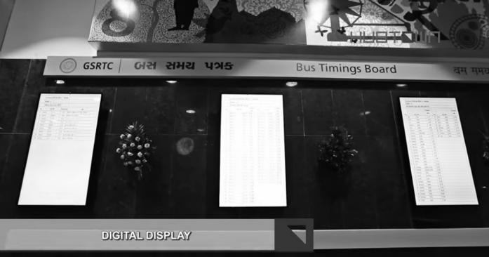
Scope: Mixed use development, including BTF, residential, hotel/services apartments, commercial and retail (woodsbagot., 2017)
3.4.11. BUS PORT AND ITS DIFFERENT UNITS
The amenities available in the new Geeta Mandir Bus Port 1, Ahmedabad are Wi-Fi connectivity with trolley, wheel chair, waiting rooms, canteen, restaurant, 12 Computerized Ticket Windows, Inquiry Centre, Digital Display Board for Bus Details and time table, Deluxe waiting room, Wheel chair, golf cart for aged, Luggage trolley, Sitting Arrangement, Canteen and Restaurant, Retail Supermarket, Shopping Mall, Food court, Ample Parking space for private vehicles, Water cooler, 14 lifts, Rest room for Drivers and conductors and more. First and second floor of New Geeta Mandir Bus Stand is used by GSRTC and upper floor is used for commercial activities. 27
INTER – CITY BUS TERMINAL AT BANEPA Aakash Bhochhibhoya 115
27 You Tube, (2015, Aug 6). Tv9 Gujarati. Retrieved from https://www.youtube.com/watch?v=KXl3GOcRNEY, viewed on Jan 15,2017 at 5:25 pm
Figure 3-63 : Ample private vehicles parking space of 4,000 sq. ft.
Figure 3-64 : Real time digital display board for bus time detail
The other units like; Eatery, Lifestyle, Entertainment, Health and Education, are all available in the bus port. The bus port services total 1,836 buses which travels around 8.5 lakhs km per day. With 3 lakhs daily commuters and over 2 lakhs business travelers a day, this signature project added a sustainable development and inclusive growth to this part of the city. Besides everything else, there is complete transformational value to the way the community looked at developing its commerce and culture. With the population exceeding over 60 million, a strong an exceptional transportation facility is the need of the hour. And, the bus port is driving the city to its horizon, benefiting millions of travels across the state. 28
3.4.12. ACCESS
The access to the site is from the west side of the terminal through 12 meters wide road and exit is through north side to 12 meters road. Separate entry and exit of the terminal solved the problem of overcrowding during rush hours. (Town, 2015)
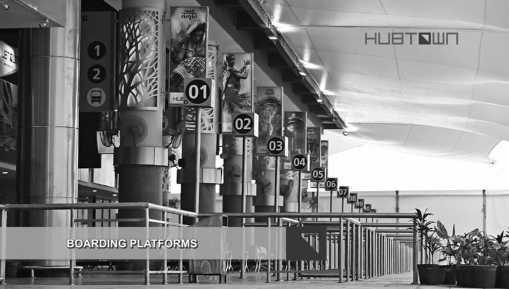

INTER – CITY BUS TERMINAL AT BANEPA Aakash Bhochhibhoya 116
28 Sandesh News, S. (2015). New Bus Stand Inaugurated by CM Anandiben Patel in Ahmedabad Sandesh News - YouTube. Retrieved from You Tube: https://www.youtube.com/watch?v=PkNg-4r3BNA , viewed on Jan 15,2017 at 5:25 pm
Figure 3-66 : Entry and exit access
Figure 3-65 : 25 Boarding platforms
3.4.13. SECURITY
Source: https://maps.google.com/, photo of August, 2016
The continuous flow of people, vibrant space and 24/7 CCTV surveillance helped in maintaining security in the terminal building. 29
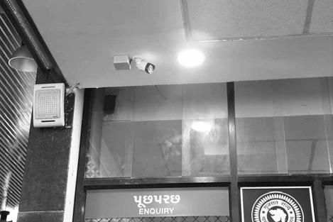
3.4.14. TICKETING, INFORMATION AND COMMUNICATIONS
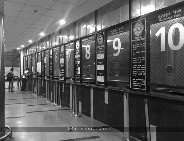
Source: https://maps.google.com/, photo of August, 2016
The use of advanced technologies (or Intelligent Transportation Systems) to improve customer convenience, speed, reliability, and safety had been explored. Examples include systems that provide traffic signal preference for buses at intersections and cross streets, as well as Global Positioning Systems (GPS) 30 had provided passenger information including real time bus arrival information. 31
29 You Tube, (2015, Aug 6). Tv9 Gujarati. Retrieved from https://www.youtube.com/watch?v=KXl3GOcRNEY, viewed on Jan 15,2017 at 5:25 pm
30 Ltd, U. C. (2015). GSRTC Bus port Ahmedabad PPP Model - A Film by Unison Communications Pvt. Ltd. AhmedabadYouTube. Retrieved from https://www.youtube.com/watch?v=lviaUpuG7_o , , viewed on Jan 15,2017 at 6:30 pm
31 GIDB, GoG. (2015). Bus Rapid Transit System, Ahmedabad. In Bus Rapid Transit System, Ahmedabad (p. 83). Ahmedabad, India: AMC & AUDA.
Aakash Bhochhibhoya 117
INTER – CITY BUS TERMINAL AT BANEPA
Figure 3-67 : CCTV surveillance
Figure 3-68 : Ticket counter and information desk
3.4.15. PUBLIC WASHROOMS
The well designed washrooms for male, ladies and physically challenged people are symbolized proper and hygienic. (Tube, Geeta Mandir Bus Port, GSRTC, 2015)
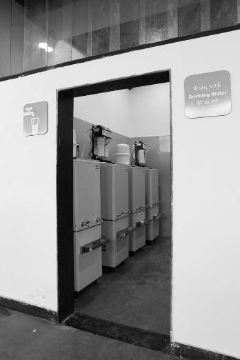
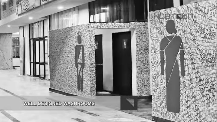
3.4.16. WATER SERVICE
3.4.17. WAITING AREA
The bus port consists of 3 different waiting area; General waiting, Ladies waiting and Deluxe A/C waiting area. 32 The waiting area for staffs (bus drivers and conductors) are also provided. Waiting areas are also the social interactive spaces.
32 You Tube, (2015, Aug 6). Tv9 Gujarati. Retrieved from https://www.youtube.com/watch?v=KXl3GOcRNEY, viewed on Jan 15,2017 at 5:25 pm
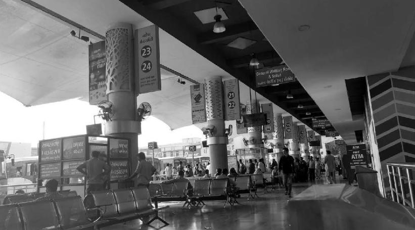
INTER – CITY BUS TERMINAL AT BANEPA Aakash Bhochhibhoya 118
Figure 3-69 : Public wash rooms
Figure 3-70 : Clean drinking water for public
Figure 3-71 : General waiting area
3.4.18. OTHER FACILITIES
3.4.18.1. REST ROOMS
The rest rooms for passengers and staffs are also available.
3.4.18.2. HYGIENE
The hygiene of the bus port is well managed.
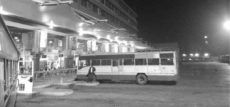
3.4.18.3. LIGHTING
Lighting facility is well-designed even during night time.
3.4.19. ARRIVAL AND DEPARTURE BERTH
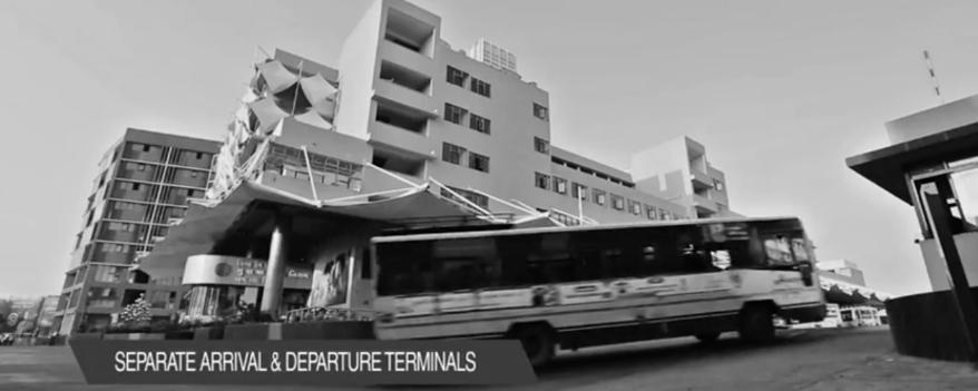
Separate arrival and departure solved the problem of overcrowding during rush hours.
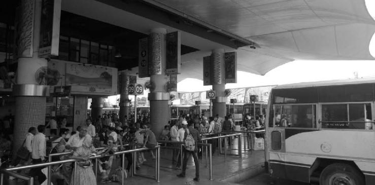
INTER – CITY BUS TERMINAL AT BANEPA Aakash Bhochhibhoya 119
It includes 25 boarding platforms, 6 alighting platforms and 23 ideal platforms. 33
33 GSTRC Gujarati and Hub Town. (2015). You Tube. Retrieved from https://www.youtube.com/watch?v=-E2qrwWGLCE viewed on Jan 19,2017 at 2:41 pm
Figure 3-72 : Lighting during night time
Figure 3-73 : Passengers waiting in berth
Figure 3-74 : Arrival gate
3.4.20. AUTOMOBILE CARE CENTRE (AMC)
Maintenance and Repairing in automobile maintenance workshop has saved the time and provided clean and safe transport.
3.4.21. ANALYSIS
NEED
It is accessible to all the users including the wheel chair users. Parking of private cars and cycles are also provided. The comfort zone inside is optimum. ETFE provided the shade and aesthetic element. The station is free from accident and crime because of enclosed and barrier structure. The separate entry and exit of vehicle; 12 m wide road, and passengers made the easy processing.
SIZE
The sizes differed from number of passengers who comes for travelling and for shopping. Total land area of 32,534 sq. m. including 3 commercial blocks; Block A,B,C (South block only) is catering 1,836 buses which travels around 8.5 lakhs km per day with 3 lakhs daily commuters and over 2 lakhs business travelers a day properly.
LOCATION
Bus port is located side by Geeta Mandir road and nearby densely populated areas also including textile factory. It formed a component in the hierarchy of transport systems. It is located in minimum impact area. The concentration and dispersal cost is minimum. It is located such that as point of coordination and integration between intercity and intra-city transport. Also, transportation of goods is easy with nearby commercial complex and textile factory.
DESIGN
It not well designed and also segregate the bus and non-bus traffic. Segregation of pedestrian and vehicular movement is also maintained. Separate entry and exit system, and also entry of private cars from different path resulted in vehicular traffic conflict. Minimum processing for buses route to the terminal is maintained by locating bus terminal in major route access (Geeta Mandir road). Way finding is ease with the help of proper signage and digitalized information board. Waste management is maintained through dustbins in whole bus terminal area. Proper lighting system during night time helped in safe and easy for night travelling.
INTER – CITY BUS TERMINAL AT BANEPA Aakash Bhochhibhoya 120
3.5. CASE STUDY 5 : ISBT KASHMERE GATE, NEW DELHI
3.5.1. GENERAL INFORMATION
The ISBT KASMIRI GATE Bus terminal (Inter State Bus Terminal) is the oldest and one of the biggest Inter State Bus Terminals in India, operating bus services between Delhi and 7 states. It opened in 1976. It recently went under renovation in 2013 with the aim to provide user friendly public transport services.
• Architect; v.p dhamija & rajinder kumar
• Completion; 1973
• Site area; 11 acres (44,515.46 sq. m.)
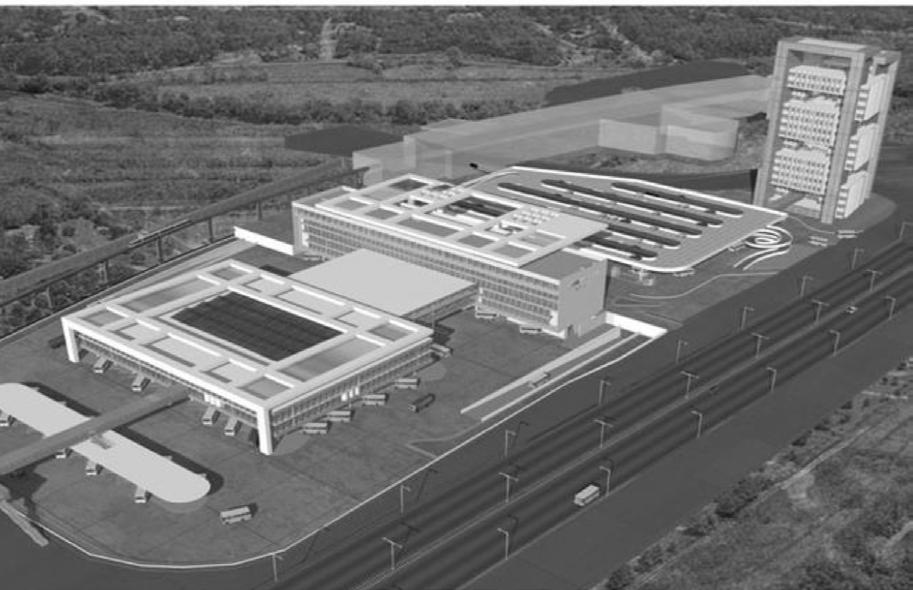
• Total number of platforms: 60
• No of platforms in arrival block: 14
• No of platform in departure block : 46
• No of arrival /day : 1851
• No of interstate services: 10
• Average no. of departure/hour : 42
• Highest no. of departure : 129
3.5.2. DESIGN PRINCIPLES
Segregation of different modes of transport and activities
Segregation of alighting and boarding platforms
Segregation of incoming and outgoing passengers at two levels
INTER – CITY BUS TERMINAL AT BANEPA Aakash Bhochhibhoya 121
3.5.3. SITE ACCESS
The ISBT has two accesses, from Rajghat & Wazirabad. (Ring road). There is one entrance to the ISBT (from Ring Road) which is common for all types of buses, though the bays are different. The passenger entrance is parallel to the metro track on the North-Eastern side. This entrance is used by office staff also.
3.5.4. SITE PLAN
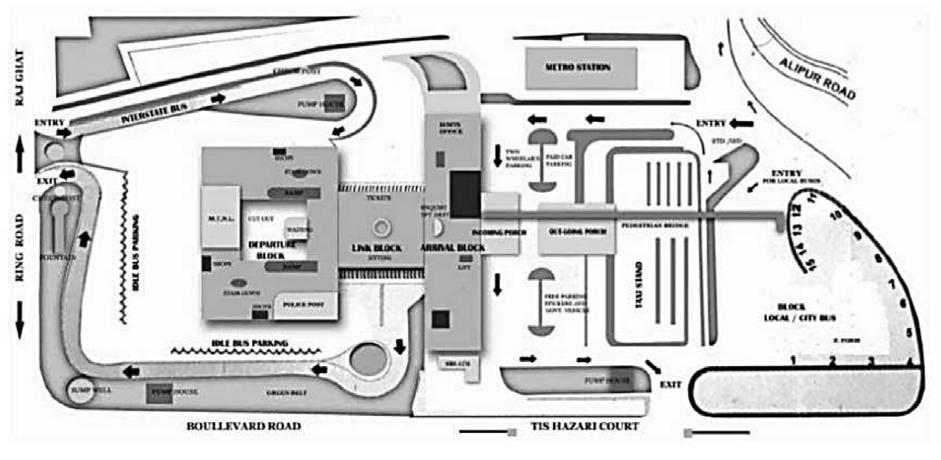
The terminal was designed in 197and is inefficient as of the current demand. The terminal is being redesigned to be a completely air-conditioned terminal with the latest security systems. The terminal is in two levels with arrivals on one side of the building and having an island departure bay for the departure block connected to the arrival block with a bridge.
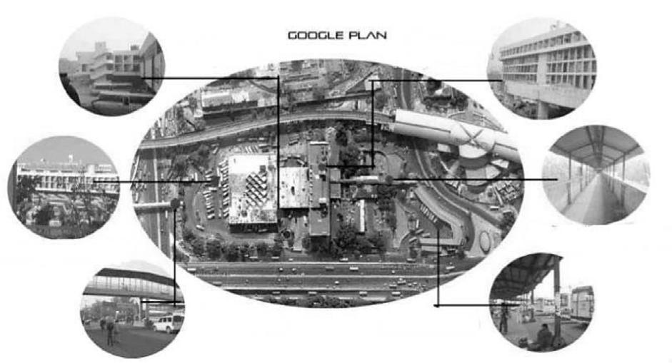
INTER – CITY BUS TERMINAL AT BANEPA Aakash Bhochhibhoya 122
Figure 3-76Master plan, ISBT Kashmiri gate
Figure 3-75 : Google plan, ISBT Kashmiri gate
3.5.5. SITE PROGRAM
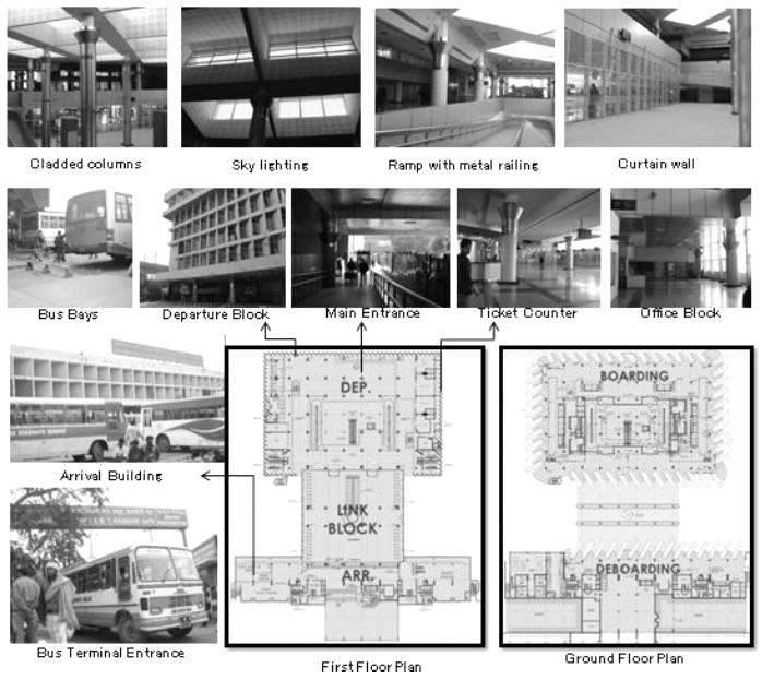
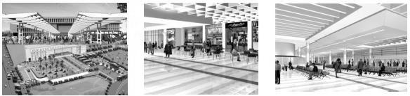
INTER – CITY BUS TERMINAL AT BANEPA Aakash Bhochhibhoya 123
Site Area - 11.00 acre (44,515.46 sq. m.) Arrival Block- 2.380 acre (9,631.52 sq. m.) Departure Block- 3.612 acre (14,617.26 sq. m.) Total Built-up- 7.720 acre (31,241.76 sq. m.) Idle Bus Parking- 31 Alighting bus bays- 14
Figure 3-77 : 3D images of Parking area, Main entrance Food courts, waiting areas
3.5.6. MATERIALS
Metal sheet cladded columns
Vitrified tile for flooring
Perforated gypsum board in the false ceiling
Half tile and half plaster walls. Glass curtain walls.
3.5.7. PLANNING
In the departure block two ramps and two staircases are provided to connect main lounge.
An over bridge is also provided to connect interstate terminal building to dtc block.
A subway to access DTC buses has been provided, which segregates the movement of passengers using the local and the interstate buses
3.5.7.1. DEPARTURE BLOCK
It is divided into two levels. The lower one for the use of outgoing passengers and buses. And the upper level for waiting out seating purposes. A mezzanine is also provided to house the offices and rest rooms of bus crew. The upper level is not being used to its full extend, hence creating congestion at lower level. Kiosk and stalls have been located between the bus bay and waiting area and attract lot of passengers to come. This crowd clocks the bus bay view from waiting are resulting in the congestion on concourse while the waiting area remains empty.
Main entrance level at first floor whit a car pouch links the enter lounge with post offices, enquiry and banks. A large enquiry desk at the entrance in the first floor. Sufficient no of public amenities (toilets and drinking water facilities) are provided. The waiting lounge is air conditioned but no smoking room is provided. The fifth floor has transit hotels which are now being used as office of Delhi administration. The sixth floor is designed for residential use of full time staff.
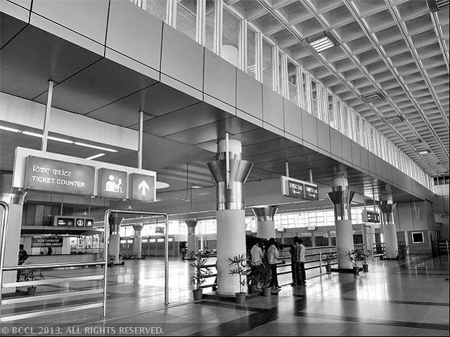
INTER – CITY BUS TERMINAL AT BANEPA Aakash Bhochhibhoya 124
Figure 3-78 : Material used in interior
3.5.7.2. LINK BLOCK
It is a connecting block between arrival and departure block at first floor level. This block was designed for ticket booths for each parking berth. Now 90% of the ticket booths provided here is not used as they have set up their counters (current booking) at departure level. Sky light has been used to bring natural light in this area. These are both circular and conical. Small enquiry offices of different state tourism and small security cell are provided in the center around a large hollow column which acts as the sky light for the arrival block below. There is a large waiting area to facilitate passengers. The waiting area in the link block is not used as much because passenger have tendency to wait near the departure platform of the bus. The counter in the link block being used for advance reservation facilities.
3.5.7.3. ARRIVAL BLOCK
• The ground floor has angular bus bays for arrival passengers.
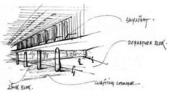
• Subway for transit passengers from arrival to departure block.
• Office space for apart provided in the mezzanine floor.
• The lack of proper signage.
• Same entrance for the staff and the visitors.
Section of the building complex with 7 storey of arrival block
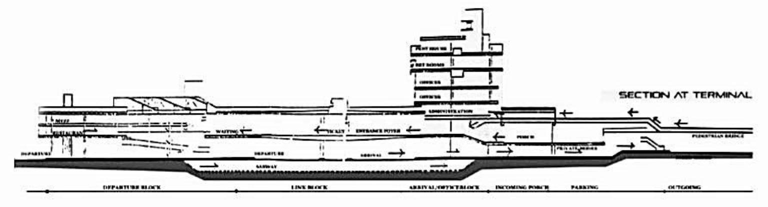
INTER – CITY BUS TERMINAL AT BANEPA Aakash Bhochhibhoya 125
Figure 3-79 : Link block
Figure 3-80 : Section of building complex, ISBT Kashmiri gate
Ground floor
It is an arrival block having 19 unloading platforms. Angular bays are provided for the unloading operation. Control room, enquiry counters, tourist information counters. The space is dull and dark due to insufficient natural light. There are sufficient numbers of public amenities provided in this area. There are many eating joints but no smoke outlets are provided.
First floor
The main entrance level of the first floor links the outgoing porch to entry lounge and facilities like post offices, enquiry and bank are provided at this level.
Second floor
Maintenance and administrative staff is accommodated on the second floor
Third floor
The various transport company offices and other terminal staff on the third and fourth floors.
Fourth floor
At fourth floor the roof of the corridor has been lowered down to accommodate the service pipes fifth floor of upper levels.
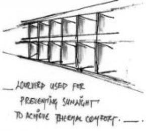
Fifth floor
Fifth floor was designed to accommodate the transit hotel for overnight staying passengers, but now the complete floor is used as officers of Delhi administration for earning revenue.
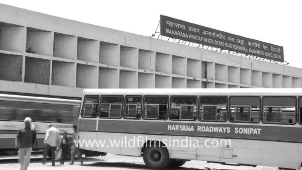
Sixth floor
Has been designed for residential use by time staff and some administrative staff with the facilities of double bed room flat and single bedroom flat.
Louvers have been provided for better living accommodation.
INTER – CITY BUS TERMINAL AT BANEPA Aakash Bhochhibhoya 126
Figure 3-81 : Louver design
3.5.8. ANALYSIS
Circulation: There is separate entry and exit points for intercity and intra city busses. This terminal has a very effective circulation pattern. There is segregation in circulation of buses and non-bus (other light vehicles) traffic due to the difference in movement character. There is a separate entry and exit points for inter-city and intra-city bus services. Segregation for vehicular and pedestrian movement. Staff and passengers have the same entrance.
Structure: The terminal has a column and beam structure. It has coffered slab to achieve long span. Thereby, reducing the number of column and increasing the free space inside. Skylights are provided for natural illumination in the terminal and one large conical skylight in the center.
Infrastructure: The amenities provided in the terminal such as toilets and drinking water are not sufficient for the users.
Thermal comfort and day lighting: The entire building is quite cool in the summer because it is heavily louvered on all sides which prevent the direct sunlight. Preventing direct heating of the internal areas. The massive roof lights over the departure area aid in natural lighting. The building becomes very chilly in the winters, since it is open on all sides, and there is no protection from the cold draught. Whatsoever, since the loading and unloading areas are partially or wholly covered, this leads to a lot of the polluted air getting trapped inside the waiting areas.
3.5.9. INFERENCES
• Segregation - different modes of transport and activities
- Alighting and boarding platforms
- Incoming and outgoing passengers at two levels
- Vehicular and pedestrian movement
• Separate entry and exit points for inter-city and intra-city bus services
• Angular bays for loading platforms >> efficient for loading operation & require less area.
• Passenger has clear approach to entry door.
• Area required per vehicle is less.
• Unloading platforms not provided.
• Area of restroom for bus crew staff and waiting areas insufficient
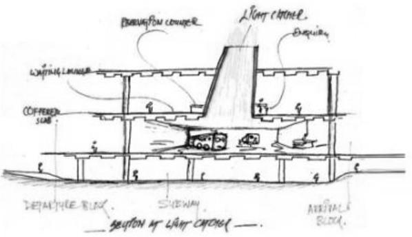
INTER – CITY BUS TERMINAL AT BANEPA Aakash Bhochhibhoya 127
Figure 3-82 : Section showing skylight in departure area
3.6. CASE STUDY 6 : SUVARNABHUMI AIRPORT, BANGKOK
3.6.1. GENERAL INFORMATION
• Location: Bangkok, Thailand
• Constructed: 1995 – 2006 A.D.
• Design: Helmut Jahn of Murphy / Jahn Architects
The passenger terminal complex at Suvarnabhumi Airport resulted from an International Competition and established the basis of collaboration between Werner Sobek, Matthias Schuler and Helmut Jahn. The challenge was great and unusual. The task of creating a new gateway to Thailand in a tropical climate necessitated a different approach to architecture and engineering. Through the integration of the disciplines the complex problem resulted in a sophisticated, intelligent yet simple solution. After 11 years of planning and construction the Terminal is set to open for passenger traffic in late 2006.
The design took into consideration Murphy/Jahn’s experience with airport terminal design, starting in the 1950’s. Those buildings included O’Hare International Airport in Chicago and particularly the New United Airlines Terminal of the mid 1980’s and the near completed renovation of Terminals 3 for American Airlines and Terminals 2, the work in the commercial zone of the New Munich Airport which included the Kempinski Hotel, the Munich Airport Center and Infrastructure, Parking and landscaped areas and the new Terminal 2 at the Airport in Cologne/Bonn.
3.6.2. STRUCTURAL ANALYSIS
A large roof trellis structure placed over the complex of functionally separate buildings unifies the site and provides the predominant architectural image as approached from the landside. Designed to accommodate future growth of the terminal pavilion, the trellis serves an important function by shading the structures below from direct sunlight, thereby reducing mechanical loads.
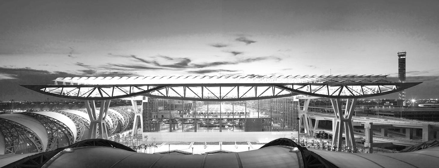
INTER – CITY BUS TERMINAL AT BANEPA Aakash Bhochhibhoya 128
Outdoor spaces between the buildings are also shaded by the roof trellis and are important to the overall concept. Rather than simply comprising empty areas reserved for future expansion, they are landscaped courtyards, useful for pedestrians and a visual amenity for the passengers in the terminal above. Cultural artifacts and traditional architectural elements are placed within these landscaped courtyards, linking the terminal complex to the cultural traditions of Thailand.
The planning of the Suvarnabhumi Airport is a masterpiece of interdisciplinary work between architects and engineers. The complexity and the size of the airport asked for new architectural and engineering solutions. The goal to create a lowenergy-need building and to design a building at the cutting edge of state-of-the-art technology required a very strict and close cooperation between all disciplines. The results are convincing, surprising and - sometimes - breathtaking.
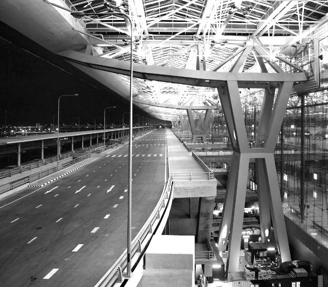
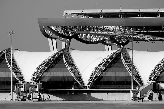
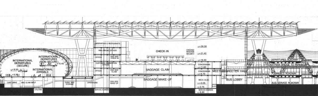
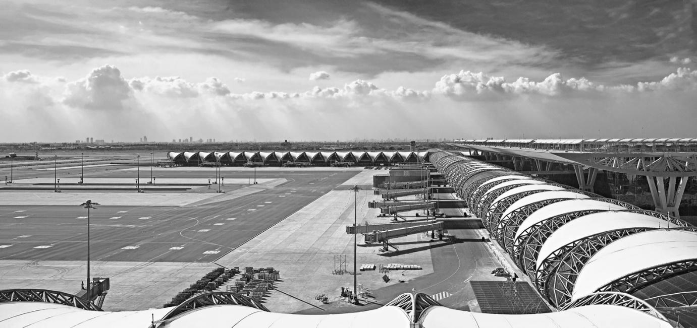
INTER – CITY BUS TERMINAL AT BANEPA Aakash Bhochhibhoya 129
Figure 3-84 : Roof trellis
Figure 3-83 : Section thru terminal pavilion
Figure 3-85 : Super truss system
The roof structure of the Suvarnabhumi Airport has a size of 567m by 210 m in plan and is comprised of 8 super truss girders. These girders have a central span of 126 m and two cantilevering ends, which both have a length of 42 m. The entire roof is supported by 16 frame-type steel columns. Creating the architectural form by its function, the geometry of the super truss girder was determined through the level of the bending moment.
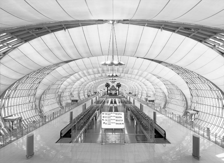
The glazed Terminal Building is placed in the center below the roof structure. It has a size of 444 m by 111 m in plan and is comprised of cable facade walls with a height of about 35m. To guarantee lifelong high performance and low maintenance costs sunshade louvers, comprised of mill finish aluminum, are positioned on top of the roof structure. They have been designed to shade the Terminal Building from direct sunlight still allowing diffuse indirect lighting to enter the Terminal Building. Because the sun shading louvers have been positioned outside the building envelope, the absorbed solar heat will be transmitted to the environment by natural ventilation creating an energy saving ecological solution.
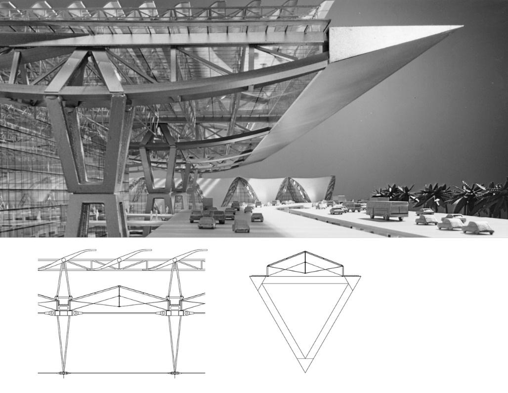
INTER – CITY BUS TERMINAL AT BANEPA Aakash Bhochhibhoya 130
Figure 3-86 : Detail drawing of super truss girder of span 126 m
Figure 3-87 : Indoor space with glazed and translucent material
With the measurements described, it was possible to control the light and heat transmission creating a highly transparent building which is matching both highest thermal and visual comfort requirements.
The concourse enclosure, which will house the hold rooms and passenger transportation means, is comprised of 5-pin arch truss girders with an alternating system of glazed facades and a translucent fabric membrane set-up, which is spanned to bridge the 27 m spacing between the glass facades. The laminated glass of the glass facade will receive a sun protection coating and a ceramic frit of variable densities. While the fritting is relatively dense at the rooftop to achieve good solar protection against the high standing sun in Thailand, it decreases gradually towards the lower parts to allow for good views to the outside.
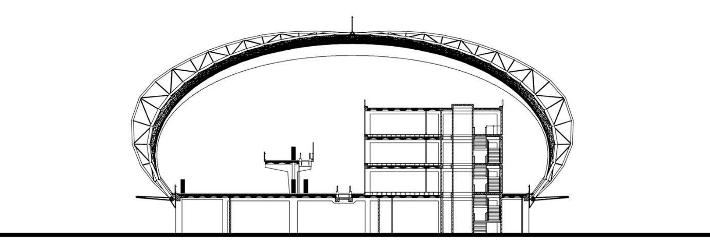
3.6.3. INFERENCE


Use of material in true expression (steel and concrete)
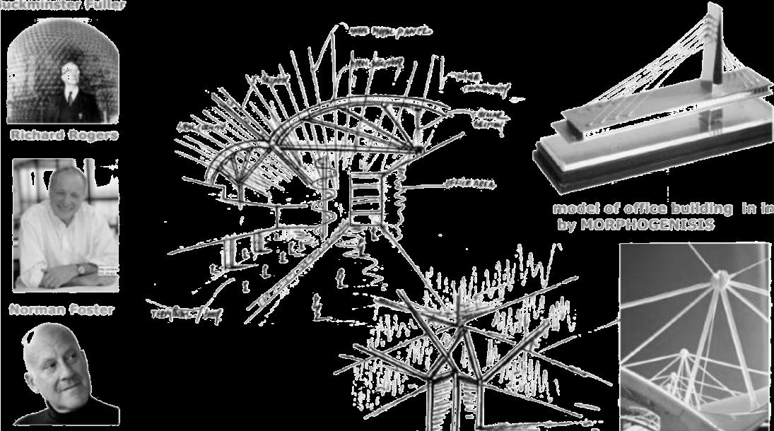
Santiago Calatrava

INTER – CITY BUS TERMINAL AT BANEPA Aakash Bhochhibhoya 131
Figure 3-88 : Concourse A & G typical section
Richard Rogers
Norman Foster
3.7. COMPARATIVE ANALYSIS LITERATURE GONGABU BUS PARK BHARATPUR BUS PARK GITA MANDIR KASHMERE GATE
Area = 161 ropanies
No. of bus = 1,250/day
Zoning: as per the flow of buses and pedestrian
Area = 96 ropanies No. of bus = 800/day
Area = 64 ropanies No. of bus = 1,836/day
Area = 87 ropanies No. of bus = 1,851/day
Design criteria: maximum efficiency To fulfill basic needs Only for terminal purpose Replace the old bus port & give facilities for all Mix-use development
Location: walkable distance Near residence area 100 m away from main highway 12 m way from Gita Mandir road
Orientation: according to site and road
Access: for all users (universal design)
N-S N-S
Maximum efficiency by segregation
Nearby main highway
Entry from west E-W
Not accessible to all Provision of ramps All users Golf cart & luggage cart
Primary componentCirculation -Bus unmanaged time to scatter Separate entry and exit (clockwise direction)
Platform: prefer radial Radial saw tooth & stepped parallel Radial saw tooth Stepped parallel
Form & planning: effective Rectangular plan with slope roof Simple form ground level planning
Building construction & structure: Long span
Well planning of space & facilities inside terminal building
R.C.C structure & truss roof R.C.C structure, truss shades, lattice truss
All users
Separate bus, private vehicles & pedestrian Vertical circulation
Stepped parallel Stepped parallel
Pure form Ground level terminal only
Pure form with play of levels
R.C.C structure, ETFE shades Coffered slab, column base, long span
Secondary - - - -
Amenities: includes both for passengers and staffs
Offices, auto workshop, fuel station, rental shop, vendors, café
No accommodation and ATM services
On air booking & advanced technology: needed
Offices, auto workshop, vendors, rental shops, café
All required amenities & rural development authority, DIMTS offices Services - - -
INTER – CITY BUS TERMINAL AT BANEPA Aakash Bhochhibhoya 132
No No
Offices, auto workshop, rental shop, café, accommodation, ATM service, Training class (12
Yes
counters) Yes
Signage & information Not proper No proper display unit Proper signage
Lighting: both artificial and natural
Ventilation: proper circulation of air and climate consideration
Emergency services: medical, security and fire escape
Landscape/outdoor activity/urban plaza: terminal as urban hub
Day-light, no such special provision Day light, no such special provision, night time – difficulty
Day light, artificial light – proper lighting
Proper use of natural lighting, skylight & light catcher
Police station Security guards Security, medical, fire escape
Vendors, no green landscape Waiting space, green landscape
First aid & public address system
No outdoor activity, cafe Transaction buses
Other services Water tank Pump house, sump well, overhead tank, metro station
INTER – CITY BUS TERMINAL AT BANEPA Aakash Bhochhibhoya 133
INTER – CITY BUS TERMINAL AT BANEPA Aakash Bhochhibhoya 134 CHAPTER 4 INFERENCE
4. INFERENCE
PRIMARY COMPONENTS
Open Planning preferred as it offers flexibility for a terminal building including rental shops. It provides an opportunity for constant interaction and visual links. An average of 20 sq. m required for open planning module.
SECONDARY COMPONENTS
Auto mobile workshop repairs and maintains the buses so to make the environment and surrounding clean Workshop should be far from public space to not harm the passengers. For security and hazard cases police security and fire stations are needed. Rental shops and Accommodation attract and provide facilities for the passengers.
SUPPORTING COMPONENTS
Interactive information centers with informal lounges preferable for interactions Resource centers with training facility needed especially for a drivers. Informal information facility for passengers. Cafeterias as eating and working space.
CIRCULATION
Provision for stairs, lifts or ramps for circulation. The circulation to be maintained at least 25% of usable area. Parking rationing as per vehicles used with necessary circulation space.
UNIVERSAL DESIGN
Public building The needs of children, elderly and differently able are imperative part of the design process. Equity and flexibility in use should be focused.
SERVICES
Narrow building depth and open planning allows maximum daylight penetration. Means of escape and evacuation routes with modern firefighting systems are needed. Intelligent and efficient lighting fixtures to be installed. Natural ventilation reduces cost and provides comfort.
SOCIO ECONOMIC ASPECT
Terminal building design should welcome people, business man, students and other passengers. Landscape and Urban Plaza can be used as learning center, resting place and exhibition space.
INNOVATION AND DESIGN
Terminal buildings stand as symbol of innovation. Design and Planning should increase efficiency. It should set precedent for other buildings. Since, long span structures are needed, design in new technology but function and planning should be in contextual dimension
INTER – CITY BUS TERMINAL AT BANEPA Aakash Bhochhibhoya 135
CHAPTER 5 PROGRAM FORMULATION
INTER – CITY BUS TERMINAL AT BANEPA Aakash Bhochhibhoya 136
5.1.
INTER – CITY BUS TERMINAL AT BANEPA Aakash Bhochhibhoya 137
5. PROGRAM FORMULATION
AREA ANALYSIS Table 5-1 : Area analysis S. N REQUIREMENTS CASE STUD Y: GONG ABU CASE STUD Y: BHAR ATPU R CASE STUD Y: KASH MERE STAN DAR D REQ. ARE A REMARK (PEAK HOUR PASSEN GER 1 ENTRANCE LOUNGE 1.5 sq. m. 1875 25% of the peak hour passenger (5000) ENQUIRY 1 no. @ 15 sq. m. 1 no. @ 30 sq. m. 1 no. @ 20 sq. m. 1.5 sq. m. 25 sq. m. 5 attendant B. TOURIST INFORMATION 1 no. @ 20 sq. m. 1 no. @ 20 sq. m. 1 no. @ 20 sq. m. 6 sq. m. 30 sq. m. 5 attendant C. TICKET BOOTH 5 sq. m. As per no. of bay D. BOOK STALL 10 sq. m. 20 sq. m. 2 no. E. PUBLIC TELE 6 no. @ 7 sq. m. 6 no. @ 18 sq. m. 2 no. @ 7 sq. m. 70 sq. m. 70 sq. m. 10 booth F. TOILET 2 sq. m. / WC & 5 sq. m./W C for wheel chair & WC –1/250 for male; 1/100 for female; urinal –1/50 male, WC for wheel chair
INTER – CITY BUS TERMINAL AT BANEPA Aakash Bhochhibhoya 138 urinal – 1/200 male female 2 WAITING HALL 1 no. @ 20 sq. m. 1 no. @ 50 sq. m. 2 sq. m. 750 sq. m. 15 % of peak hr. passenger in ½ hr. cycle KIOSK 10 sq. m. 60 sq. m. 6 no. B. TOILET 6 no. @ 18 sq. m. same M –23 sq. m. F – 12 sq. m. 30 % of the loading bay capacity C. DRINKING WATER 4 no. 3 DEPARTURE LOUNGE 2 sq. m. ENQUIRY 1 no. @ 15 sq. m. 1 no. @ 30 sq. m. 1 no. @ 20 sq. m. 5 sq. m. 2 attendant B. KIOSK 18 no. @ 9 sq. m. 9 no. @ 12 sq. m. 12 no. @ 7.5 sq. m. 10 sq. m. C. DRINKING WATER 5 no. @ 5 sq. m. 7 no. @ 3 sq. m. 12 no. @ 5 sq. m. 3 sq. m. D. TICKET BOOTH 15 @ 5 15 @ 5 10 @ 5 5 sq. m. E. TOILET 8 no. @ 18 sq. m. 6 no. @ 18 sq. m. 10 no. @ 18 sq. m. 2 sq. m. / WC &
INTER – CITY BUS TERMINAL AT BANEPA Aakash Bhochhibhoya 139 5 sq. m./W C for wheel chair & urinal 4 ARRIVAL LOUNGE KIOSK 12 no. @ 9 sq. m. 6 no. @ 12 sq. m. 6 no. @ 7.5 sq. m. 2 stalls each B. DRINKING WATER 2 no. @ 5 sq. m. 2 no. @ 5 sq. m. 4 no. @ 5 sq. m. C. TELE. BOOTH 9 no. @ 7 sq. m. 5 no. @ 7 sq. m. D. TOILET 4 no. @ 18 sq. m. E. TOURIST INFO. 1 no. @ 20 sq. m. 1 no. @ 20 sq. m. 5 ANNOUNCEMENT & REPORTING 1 no. @ 25 sq. m. 1 no. @ 25 sq. m. 30 sq. m. 1 no. 6 BUS CREW STAFF 625 sq. m. CAFETERIA 160 sq. m. 160 sq. m. B. DORMITORIES 420 sq. m. 420 sq. m. C. LOCKER 45 sq. m. 45 sq. m.
INTER – CITY BUS TERMINAL AT BANEPA Aakash Bhochhibhoya 140 7 COMMUTER FACILITIES A. BARBER SHOP 2 @ 20 30 sq. m. 30 sq. m. B. DORMITORY 1 no. @ 30 sq. m. 2 no. @ 50 sq. m. 128 sq. m. 4 no. @ 32 sq. m. for 10 beds. C. CHEMIST 1 no. @ 9 sq. m. 30 sq. m. 30 sq. m. 1 no. D. DISPENSARY HEALTH UNIT 1 no. @ 30 sq. m. 50 sq m. 50 sq. m. 1 no. E. RESTAURANT 5 no. @ 30 sq. m. 2 no. @ 75 sq. m. for 15 passeng ers 1.2 sq. m. / person 300 sq. m. 1 no. 8 MISCELLANEOUS 690 sq. m. 1 no. BANK 2 no. @ 15 sq. m. 150 sq. m. 150 sq. m. 1 no. B. POST & TELEGRAPH 1 no. @ 15 sq. m. 80 sq. m. 1 no. C. POLICE POST 1 no. @ 30 sq. m. 1 no. @ 25 sq. m. 1 no. @ 25 sq. m. 150 sq. m. 150 sq. m. 1 no. D. PUMP ROOM 1 no. @ 15 sq. m. 1 no. @ 12 sq. m. 1 no. @ 80 sq. m. 150 sq. m. 2 no. E. AIR BOOKING COUNTER 80 sq. m. 1 no.
5.2. AREA CALCULATION
PROPOSED PROGRAM IN REFERENCE TO CASE STUDIES
The inter-city bus terminal is to be designed to handle 516 ~ 600 trips per day
Daily flow = 516 ~ 550 buses in Banepa Bus Station
Peak hour flow = 10 % of total daily flow = 55 buses
Loading – efficient loading operational time = 12 minutes
Bay capacity in peak hour = 60 min / 12 min = 5 No.
Unloading – efficient unloading operational time = ½ loading operation = 6 minutes
Bay capacity in peak hour = 60 min / 6 min = 10 No.
No. of Bays for loading and unloading = total no. of buses in peak hr. / bay capacity in 1 hr.
No. of Departure bays => 55 / 5 = 11
No. of Arrival bays => 55 / 10 = 5
Total no. of bays for loading and unloading = 16 bays
Average no. of passengers in a bus = 36
No. of passengers in peak hour in a bus = 50
Peak hour departing and arriving passengers = 50 x 16 = 800 passengers
Maximum footfall inside bus terminal= 5 times the total peak hour passengers = 5 x 800 = 4,000
Bus terminal footfall projected = 3,000 – 4,000 including for commercial purpose
INTER – CITY BUS TERMINAL AT BANEPA Aakash Bhochhibhoya 141 F. RAIL BOOKING COUNTER 1 no. @ 25 sq. m. -9 OFFICE A. MANAGER’S ROOM 1 no. @ 20 sq. m. 1 no. @ 25 sq. m. 1 no. @ 15 sq. m. 1 no. @ 25 sq. m. 25 sq. m. 1 no. B. IN-CHARGE ROOM 1 no. @ 20 sq. m. 1 no. @ 15 sq. m. 1 no. @ 15 sq. m. 1 no. @ 15 sq. m. 20 sq. m. 1 no. C. ACCOUNTS OFFICE 1 no. @ 25 sq. m. 1 no. @ 30 sq. m. 1 no. @ 25 sq. m. 1 no. @ 30 sq. m. 30 sq. m. 1 no. D. ADMINISTRATIVE OFFICE 1 no. @ 25 sq. m. 1 no. @ 30 sq. m. 1 no. @ 25 sq. m. 1 no. @ 30 sq. m. 30 sq. m. 1 no.
Table 5-2 : Program formulation
INTER – CITY BUS TERMINAL AT BANEPA Aakash Bhochhibhoya 142
SN FUNCTION NO. AREA/ m2 TOTAL / m2 1 PARKING AND BUS FACILITIES A. PARKING (15 % of total) Idle parking for buses 83 108 8964 Arrival and departure lot 16 108 1728 Taxi / Auto rick saw parking 20 12 240 50 % circulation 5466 TOTAL 16,398 B. PRIVATE VEHICLES / PARK & RIDE FACILITIES 2 wheelers 120 1.7 204 4 wheelers 30 12 360 50 % circulation 282 TOTAL 846 SUB TOTAL 17,244 2 GAS STATION 1 400 400 3 WORKSHOP Store 1 45 45 Cashier 1 9.5 9.5 Reception 1 50 50 Maintenance 3 65 195 Washing 2 65 130 40 % circulation 214.75 TOTAL 644.25 4 TERMINAL BUILDING Information booth 1 70 70 Ticket counter 10 10 100 Waiting area (40 %) 320 1 320 Passenger lounge (20 %) 160 3 480 Security room 1 15 15 Baggage screening 4 200 800 Detaining room 1 50 50
INTER – CITY BUS TERMINAL AT BANEPA Aakash Bhochhibhoya 143 Baggage room 1 120 120 Administration offices (Manager, Technical, Accounts, Traffic, Control, Meeting, Training Hall) 560 Janitor’s room 1 40 40 Toilet (5 %) 40 2.8 112 30 % circulation 800.1 TOTAL 3,467.1 5 COMMERCIAL FACILITIES Restaurant (café, food court) 1 400 400 Lounge 1 100 100 Kitchen, store, offices (40 %) 2 100 200 Cyber café 1 100 100 Retail shops (small, medium, vendors) 50 15 750 Convenience store 1 260 200 Phone booth 3 5 15 Book shop (small sized) 1 150 150 ATM 8 5 25 35 % circulation 661.5 TOTAL 2,619 7 QUARTER BLOCK Bedroom (40 % of ideal parking + staffs) 34 + 10 16 704 Dining hall 200 Common room 30 Toilet 12 2.8 33.6 35 % circulation 338.66 TOTAL 1306.26 8 Emergency management Dispensary health unit 2 50 100 Fire extinguisher department 1 450 450 TOTAL 550 9 OTHERS Generator / Sub station 50 Water supply / Grease water treatment 50 TOTAL 100
Total built space = 9,234.26 m2
Allowable FAR = 3.0
Total G.C. (max. allowable 50%) = 7,610 m2 (23.2 %)
Open space (parking) = 16,398 m2
Total area => 24,008 m2
Adding 35 % for landscape and other outdoor facilities = 8,402.8 m2
Total site area = 36,339 m2
Site area in Ropanies = 71 – 6 – 3 – 2
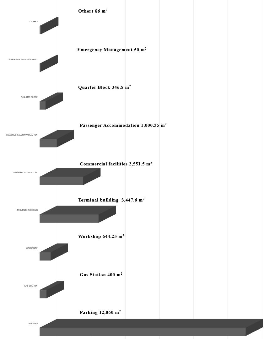
INTER – CITY BUS TERMINAL AT BANEPA Aakash Bhochhibhoya 144
Figure 5-1 : Program chart
INTER – CITY BUS TERMINAL AT BANEPA Aakash Bhochhibhoya 145
6 SITE
CHAPTER
STUDY
6. SITE STUDY
Site is very important in any project. Every project has its own requirement of site and every site has its own potential and limitation. Therefore, selection of proper site requires proper analysis. Based on the literature review and case study, many factors are considered during the selection of the site. Available of sufficient land and road access are primary criteria. Other criteria to be considered are:-
1. Location: The site should be related to major streets or landmarks previously existing.
2. Neighborhood context: Zoning of the neighborhood is important and information of this type can typically be found at the municipal planning department of the site.
3. Size and zoning: Site boundaries can be located by either verifying the dimensions physically or contacting the county tax assessor‘s office.
4. Legal: Typical legal information can be obtained from the deed to the property.
5. Natural physical features: Most of this information will be derived from the topographic features on the site.
6. Manmade features: Features located on the site such as buildings, walls, fences, patios, plazas, bus stop shelters should be noted.
7. Circulation: The uses of streets, roads, alleys, sidewalks, and plazas are important in this inventory step.
8. Utilities: Information for utilities concerning the site can be found through the utility departments and companies in the local area.
9. Sensory: This type of information is obtained from sketching and photographs (sometimes aerial photographs).
10. Human and cultural: This information includes activities among people on the site and their relationships to these activities.
11. Climate: Conditions such as rainfall, snowfall, humidity, and temperature over months must be considered and analyzed. The sun-path and vertical sun angles throughout an entire year are important to note.
6.1. SITE SELECTION BASIS
As already discussed, the main target of the proposed bus terminal is to design new bus terminal by studying the existing Banepa Bus Station. It is necessary that the site is approachable to most of the population. Also the site should be such located that it does not add pressure to the already congested valley‘s traffic routes. So the site is selected in such a way that it is not so far from settlement area nor too near. Also other vehicles leaving the Banepa valley towards the east corridor of Nepal passes through the same point. Therefore developing such an area into bus terminal will be a great effort to systematize the prevailing traffic systems.
INTER – CITY BUS TERMINAL AT BANEPA Aakash Bhochhibhoya 146
6.2. SITE JUSTIFICATION
6.2.1. EXISTING BUS STATION CONDITION AND ROUTES
In order to fulfil the objective of the project proper selection of site is a must. The site for this project should be located not very near from the dense residence area but should be with in walkable distance i.e. under 700 meters in order to be free from noise and air pollution generated by buses.
NALA RAVI
BUS BEWASAYE
PANAUTI–BANEPA KATHMANDU
TOTAL = 108 per 5 minutes
18 on hold (parking)
4 Khopasi per 30 minutes
5 Banepa per 15-30 minutes
2 Bashdol per 2 hours
KAVRE BUS BEWASAYE
TOTAL = 152 per 5 min., ½ hr., 1 hr., 2 hr.


16 on hold (parking)
TOTAL NUMBER OF BUS


ARANIKO YATAYAT SEWA SAMITY–165
KAVRE BUS BEWASAYE SANG–136
KAVRE MINI BUS SAMITY – 108
HELAMBU YATAYAT SAMITY – 74
HIMAL TERAI YATAYAT SAMITY–53
TOTAL – 516 / Day
Source: https://www.google.com.np/maps/place/Banepa/
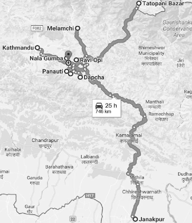
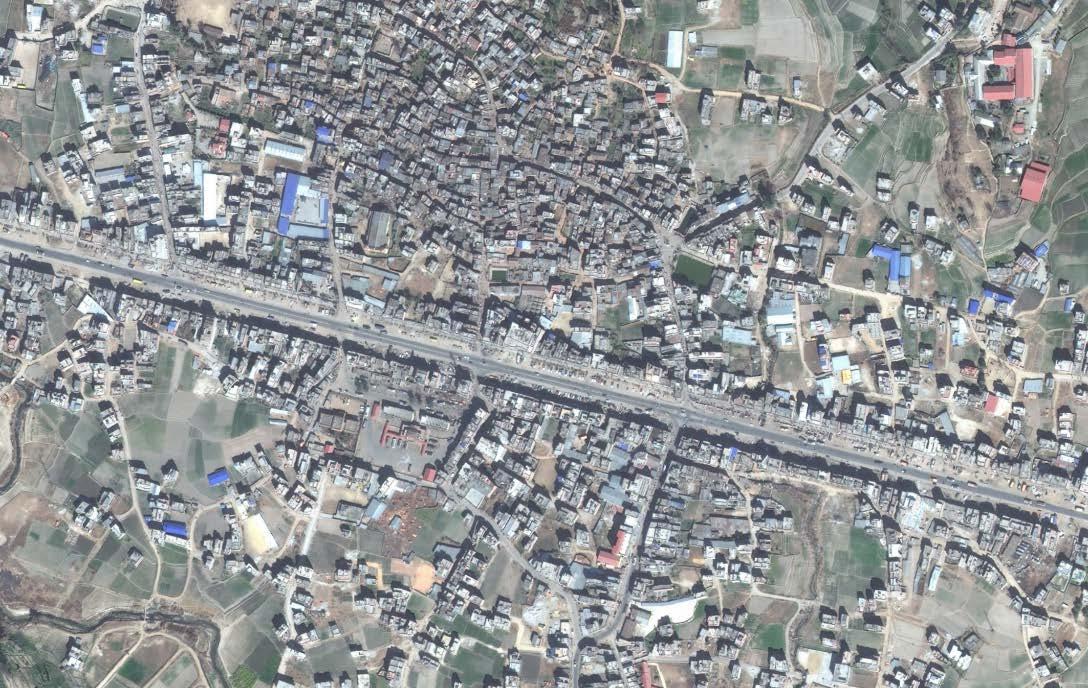
INTER – CITY BUS TERMINAL AT BANEPA Aakash Bhochhibhoya 147
PANAUTI
Figure 6-1 : Existing bus station and its surroundings and destinations
Figure 6-2 : Bus routes
6.2.2. CASE STUDY ON EXISTING BANEPA BUS STATION
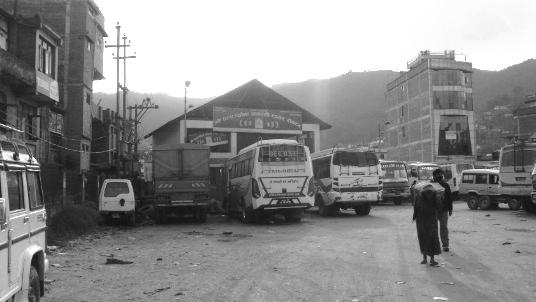
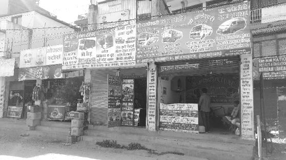
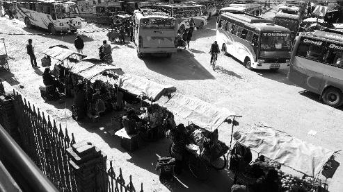
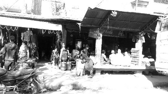
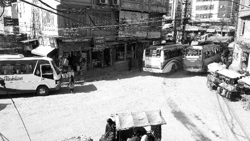
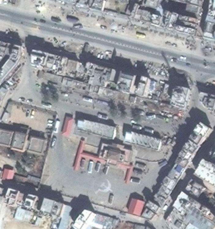
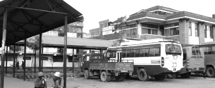
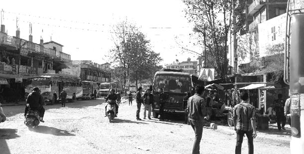
6.2.2.1. PLANNING AND CIRCULATION
Area = 6,800 sq. m. (13 – 5 – 3 – 1.8)
Surrounded by dense residence area
Circulation of Buses –Clockwise and Anti-clockwise (2 way)


Linear Parking System and separate bay island of linear trees
2 lanes and Buses – 518 / day
Tata sumo, Micro bus, Minibus, Bus
Not serving as public open space
INTER – CITY BUS TERMINAL AT BANEPA Aakash Bhochhibhoya 148
Figure 6-3 : View of bus station
Figure 6-4 : Entry and exit
Figure 6-5 : Waiting space
Figure 6-8 : Vendors
Figure 6-6 : Ticket counter
Figure 6-7 : Long term parking
Since, the present bus station is surrounded by dense residence area and also considering above statement and literature, the site for my thesis project Inter-city Bus Terminal, I have chosen area which is entrance of Banepa city adjacent to Punyamata River, Banepa. The site is located in the north corner of Banepa at around 700 meters of radius from dense residence area Banepa is developing as a commercial hub since it is one and only trade link to the china and also due to Banepa bus station, according to research.
Source: https://www.google.com.np/maps/place/Banepa/


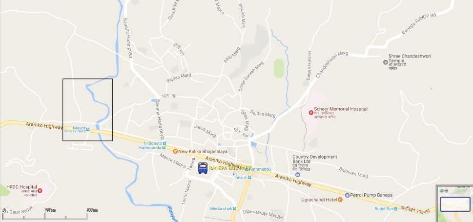
Haphazard planning of workshop, denting, painting, repairing shops and other amenities around the Pulbazar area can be centralized under the bus terminal and those areas can be planned as highway commercial zone.
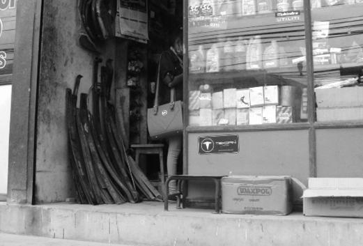
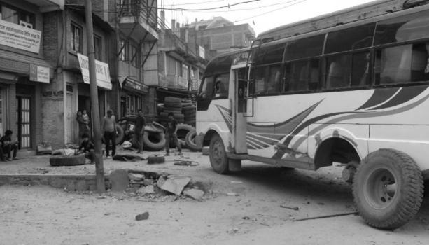
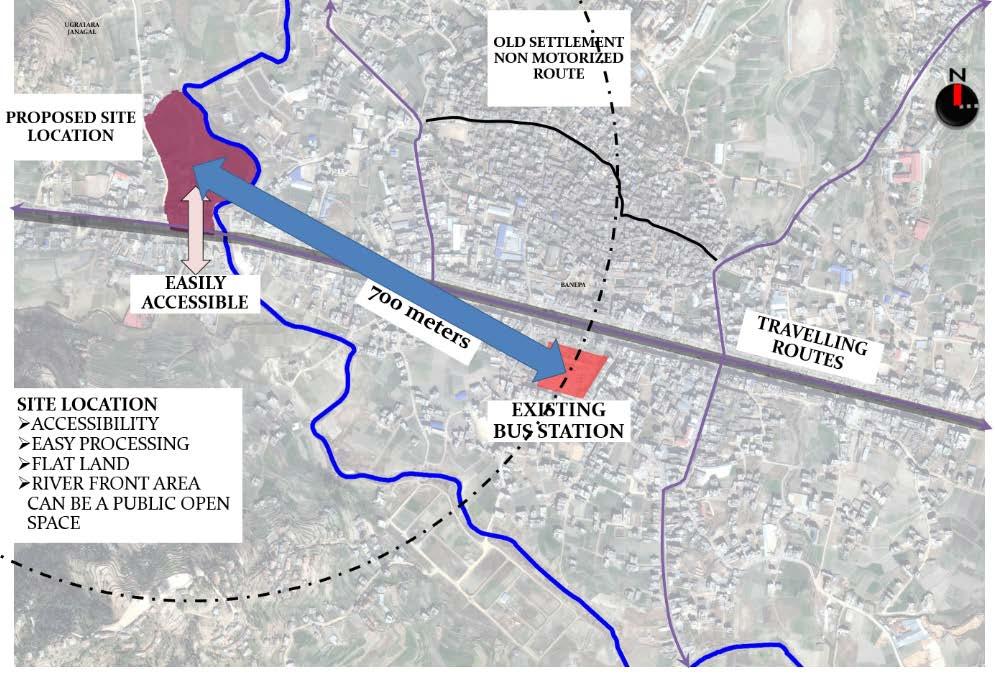
INTER – CITY BUS TERMINAL AT BANEPA Aakash Bhochhibhoya 149
Figure 6-10 : Site and its surroundings
Figure 6-9 : Site surroundings and amenities
Figure 6-11 : Workshop and repairing shops nearby site
6.3. SITE ANALYSIS
Site Analysis is necessary to understand the given site properly and the forces that determines the site condition. A study of natural determinants including topography, geology, hydrology, soils, vegetation and climate provides the basis for an intelligent approach to land development.
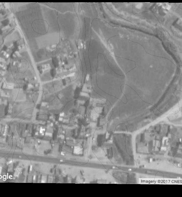
6.3.1. SITE INTRODUCTION
Location: Pulbazar, Banepa – 10, Kavre, Bagmati, Central Development Region, Nepal
Coordinates: 27°38′N 85°31′E
Altitude: 1,500 m above sea level
Area: 36,339 sq. m. (71 – 6 – 3 – 2)
Orientation: Long axis in the N-S direction


6.3.2. ACCESS AND APPROACH
The site is easily accessible from Araniko Highway and other two secondary roads of 4 m, left side and 6 m, right side, and also the pedestrian bridge connected to right side secondary road. The present width of Highway is 12 m and proposed width is 50 m including the pedestrian footpath.
Source: Banepa Municipality
6.3.3. EXISTING SURROUNDIGNS
East – River, Pedestrian Bridge, Ganesh temple, Secondary road
West – Secondary road, few number of buildings
North – Highway
South – Agriculture land
6.3.4. SOCIETY AND CULTURE
The vast majority of the population are Newar, the ethnicity that traditionally lives in the valley. With 90% Newars, this is a very homogenous community – particularly given the multi-ethnic character of Nepal. (Souce: National Population and Housing Census 2011, Kavrepalanchowk)
INTER – CITY BUS TERMINAL AT BANEPA Aakash Bhochhibhoya 150
Figure 6-12 : Access to site Source: https://www.google.com.np/maps/place/Banepa/
Nava Durga Jatra, Chandeswori Jatra, Kanya Puja, Dashain and Tihar are some important rituals take place here.
Most of the people are engaged in services and business. The cultural hub foe the urban young population with growing restaurants and commercial shops. Pollution has grown as the major problem in the area, especially in highway.
6.3.5. TOPOGRAPHY AND LANDFORM
The site is slightly elevated upwards from east to west. It consists of terraces of 1 m approximately and flat plotting land. The site has 5 number of contour of 1 m. It had been used for agriculture by the land owners at the back and residence side by highway.
6.3.6. VEGETATION
The site is rich in natural vegetation and is surrounded by native trees.
6.3.7. HYDROLOGY
The site is adjacent to the Punyamata River.
6.3.8. INFRASTRUCTURES
Water supply: presence of river itself as source of water for workshop function, which requires minimum water treatment and also provision of government water supply
Electricity: 220KV NEA
Telecommunication: landline and mobile service
Sanitation: sanitation pipe line system in and around the site. Most of the buildings directly connect to the sanitation pipe line which is not appropriate.
6.3.9. SOIL CONDITION
According to the Groundwater condition of Banepa area, Central Nepal, the soil type of the site is alluvial soil and requires minimum water treatment for deep boring water.
6.3.10. VISUAL POTENTIAL
The site does not have such a great visual potential but is visible from Highway. And, the Banepa valley and Mountain range are visible from the site.
6.3.11. LEGAL ASPECT (BY – LAWS)
As per building by-laws of 2072, the proposed site lies in the Mixed - Agriculture sub-zone (Araniko Highway)
INTER – CITY BUS TERMINAL AT BANEPA Aakash Bhochhibhoya 151
GCR = 50 % (% Of the total site area)
F.A.R = 3.0
Setbacks = 7 m from Highway (50 m width of road) = 3 m from boundary
Total built up area = FAR x Site area
6.3.12. CLIMATIC ANALYSIS
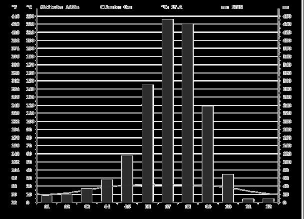
Banepa's climate is classified as warm and temperate. In winter, there is much less rainfall in Banepa than in summer. The Köppen-Geiger climate classification is Cwa. In Banepa, the average annual temperature is 17.2 °C. About 1745 mm of precipitation falls annually
Source: https://en.climate-data.org/location/56656/
Source: https://en.climate-data.org/location/56656/
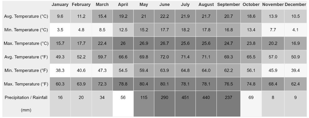
INTER – CITY BUS TERMINAL AT BANEPA Aakash Bhochhibhoya 152
Figure 6-14 : Climate table/Historical weather data Banepa
Figure 6-13 : Climate graph of Banepa; average min and max temperature
6.4. SITE IMAGES

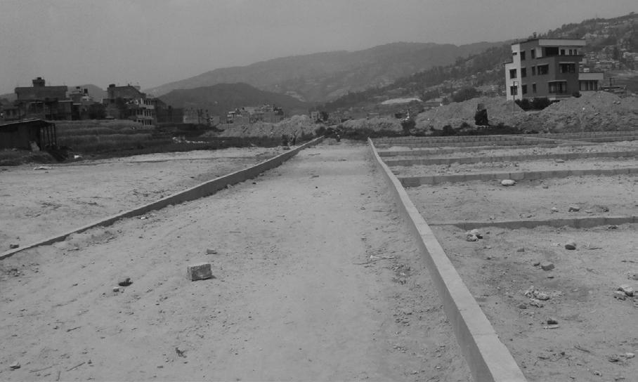


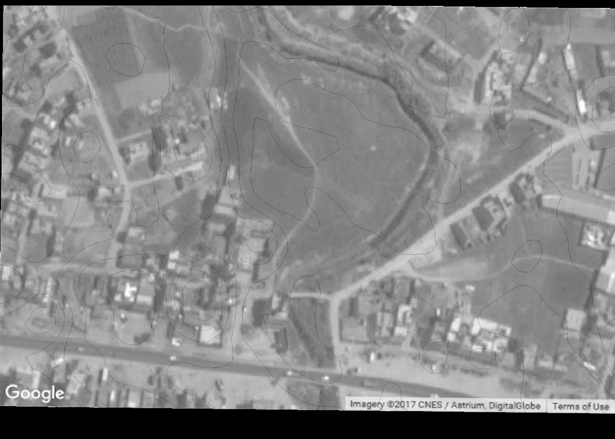
INTER – CITY BUS TERMINAL AT BANEPA Aakash Bhochhibhoya 153 4 2 1 3
1
Figure 6-15 : Open and flat land
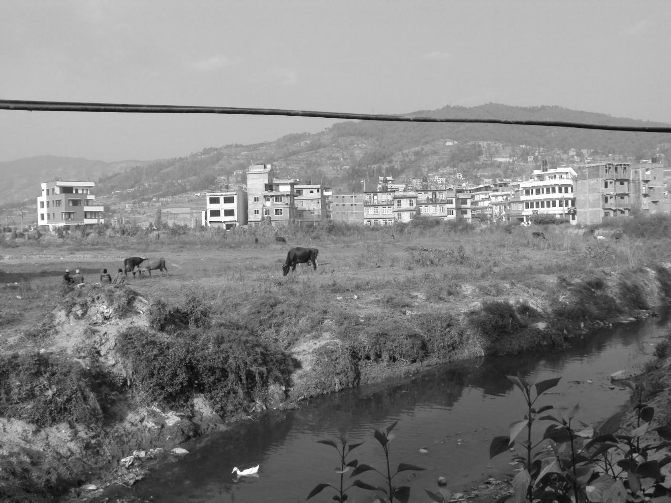

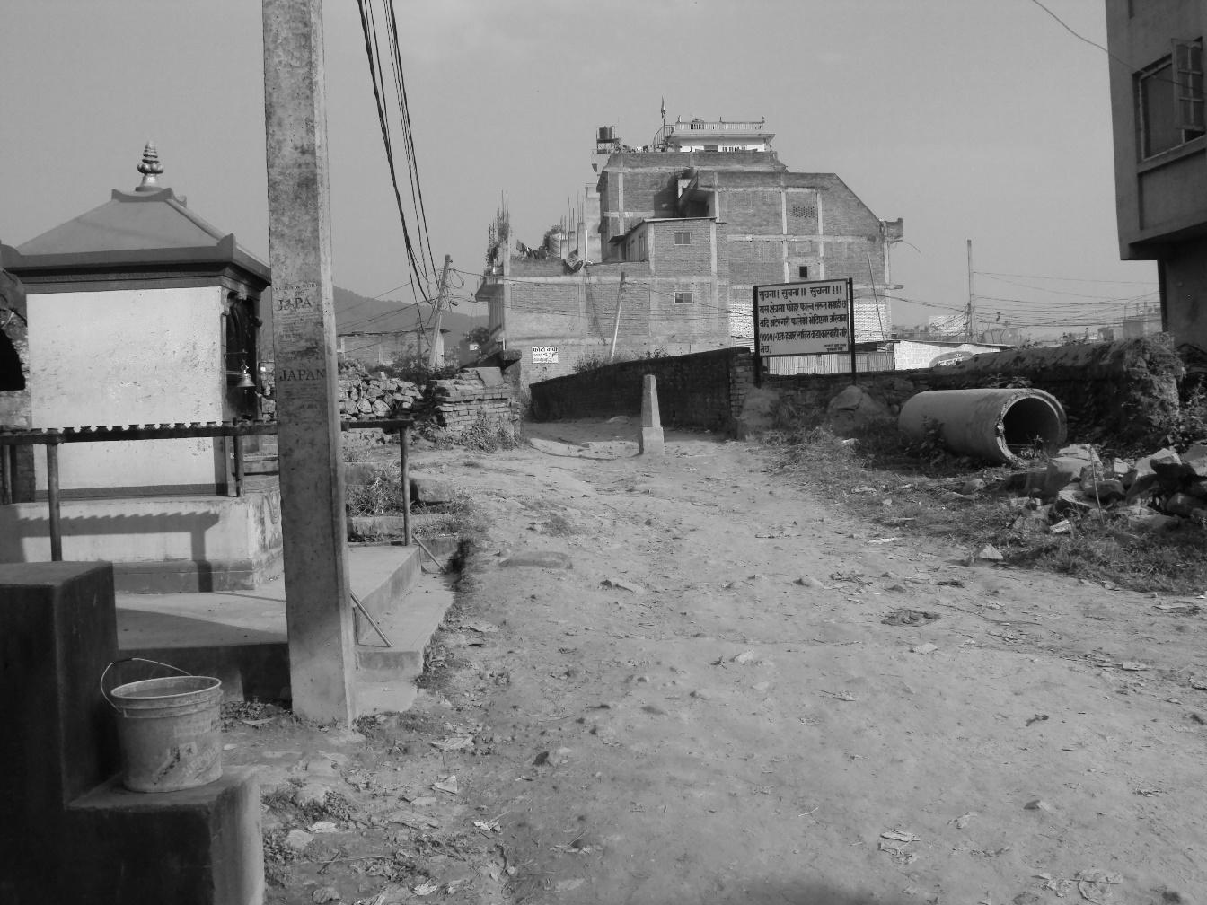

INTER – CITY BUS TERMINAL AT BANEPA Aakash Bhochhibhoya 154 1
2
Figure 6-16 : Close up of river
Figure 6-17 : Ganesh mandir and pedestrian bridge
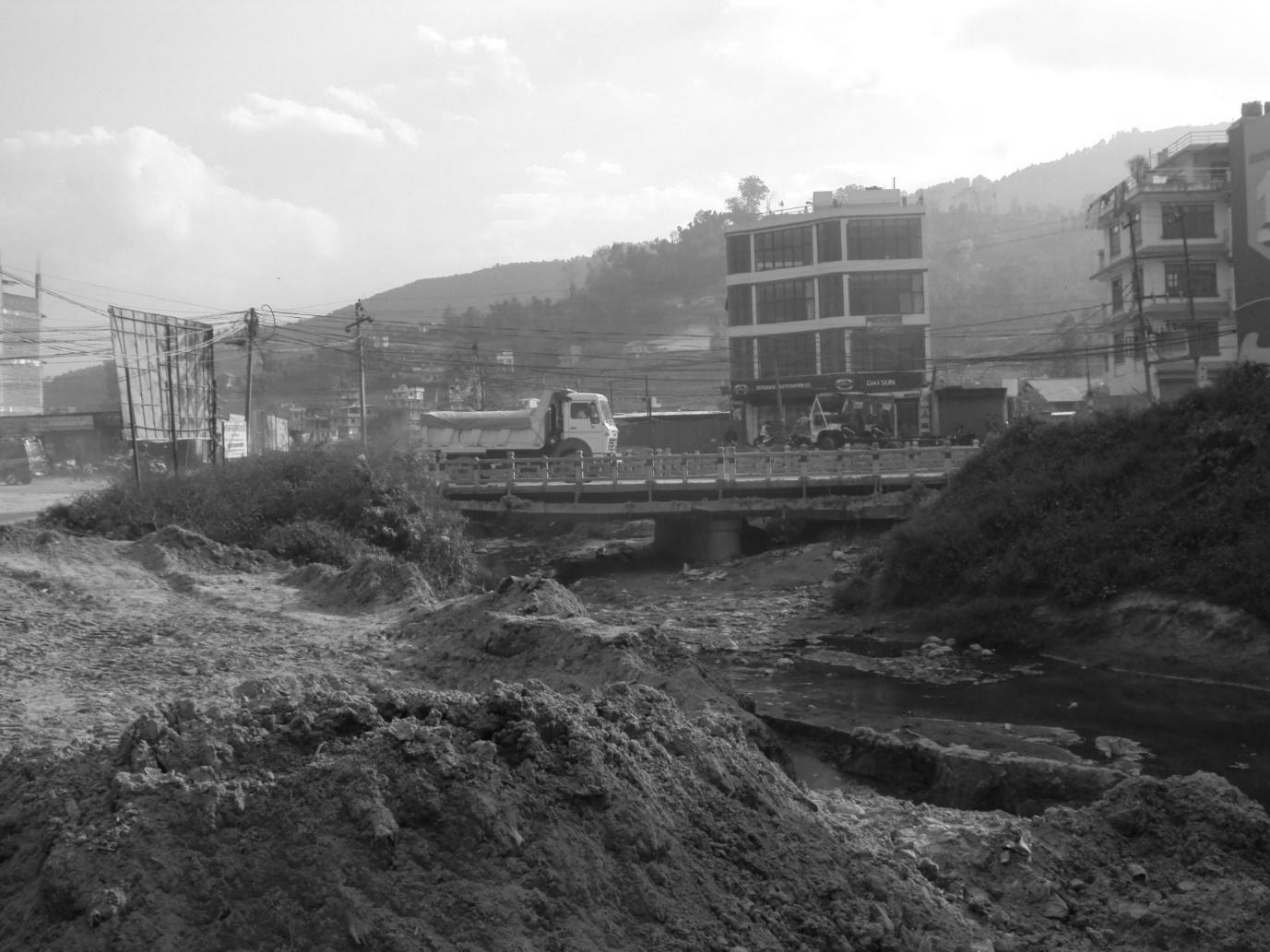
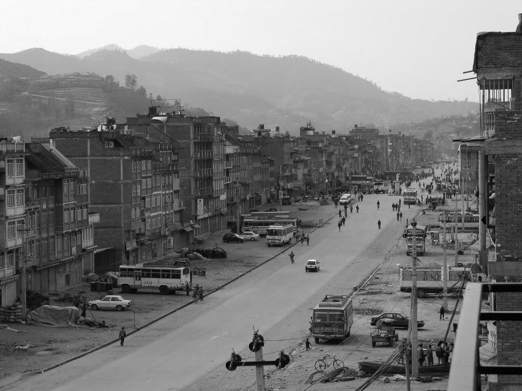
INTER – CITY BUS TERMINAL AT BANEPA Aakash Bhochhibhoya 155 3 4
Figure 6-18 : Pulbazar approach road
Figure 6-19 : Araniko highway
6.5. SITE DRAWING
The land and sea breeze directly from the Punyamata River will help to maintain balance in the temperature of the site.
6.6. SWOT ANALYSIS
6.6.1. STRENGTH
Location: Neither too near nor far from residential area.
Appropriate access roads: Roads on two sides with sufficient widths for the traffic generated and also provide ample frontage.
Approach: Connected with Araniko highway
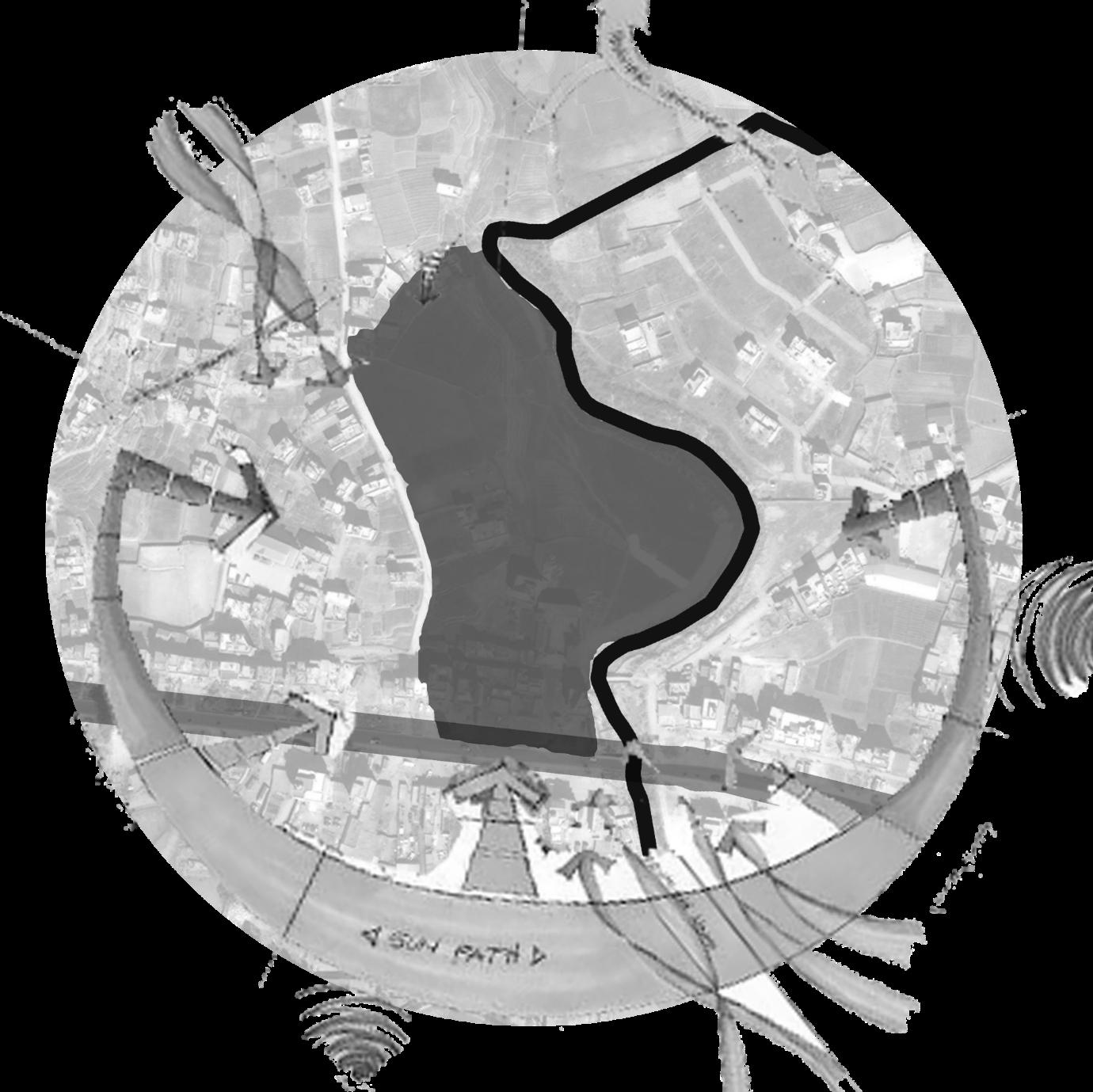
INTER – CITY BUS TERMINAL AT BANEPA Aakash Bhochhibhoya 156
Location: Primarily in proximity of residential area, makes it the focal point.
Land: Almost flat land
Commercial development
River
Orientation: South
6.6.2. WEAKNESS
Bad odor: From river
Views: No special views from the site except the flow of river.
6.6.3. OPPORTUNITIES
As well connected with public transported, there is opportunity to create universal and sustainable urban design – bus terminal including commercial area.
Access via 2 roads and an another pedestrian bridge and connected road help in planning of bus circulation, community spaces, office, commercial area appropriately
Retail development: surrounding residential area and the site encourages retail development
Scope for turning out to be a major bus terminal and commercial hub for Banepa and neighbor.
Generation of mixed use environment and chance to make a landmark in Banepa.
6.6.4. THREAT
River level increases in rainy season
Encroachment by vendors
Ecological threat
INTER – CITY BUS TERMINAL AT BANEPA Aakash Bhochhibhoya 157

INTER – CITY BUS TERMINAL AT BANEPA Aakash Bhochhibhoya 158
7
CHAPTER
DESIGN CONCEPT AND DESIGN DEVELOPMENT PROCESS
7. DESIGN CONCEPT AND DESIGN
DEVELOPMENT PROCESS
7.1. CONCEPT
- FORM FOLLOWS SITE AND MOVEMENT with mutual relation
The bus terminal is point of beginning and as well termination of different vehicular routes. Also the bus terminal is a hub for the commercial happenings related with the passenger‘s facilities. All that stroked my mind while thinking of the bus terminal at first was;
The flow of huge amount of vehicles entering and exiting from the huge terminal complex
Passengers in a long line for ticketing
The passengers waiting in a large hall before departing and some passengers busy with shopping and eating.
People waiting for arrival of guest- relatives
So whether it is man or vehicles, the first thing that comes with bus terminal in a mind are movement and the flow. And where there comes the flow of vehicular routes, different design standards, circulation pattern and turning radius becomes a vital part of the design. If proper standards are not maintained in the planning of circulation & flow. Then, only designing a beautiful building doesn‘t sufficient the need of a proper Bus Terminal.
“In many small town or even big cities, bus terminal is hub of so many activities. One should observe these activities before enlisting a set of objectives. The first set would relate to human issues: safety, security, comfort, utility etc.; the second set would be related to social and economic: it is a place for social interaction, providing linkages to other places in an affordable manner, etc.; The next would be environmental: noise, dust, pollution, shade, etc.; It would be followed by technical: the space standards for buses, their movements, parking, and different activities etc. and the last, but not the least philosophical: what the bus terminal wants to be? What people want from their bus terminal? It may be a very powerful symbol of the progress of the people or a humble but dignified place to be in! ‟ (Source: ARCHNET, objective of bus terminal) Hence, the design idea for this project will aim at designing a terminal hub which not only functions well for circulation of bus but should also respect the nature where it will grow in the site and its surrounding; city.
“FORM FOLLOWS SITE AND MOVEMENT with mutual relation”
“A building should appear to grow easily from its site and be shaped to harmonize with its surroundings if Nature is manifest there.” Frank Lloyd Wright.
INTER – CITY BUS TERMINAL AT BANEPA Aakash Bhochhibhoya 159
7.2. DESIGN INSPIRATION
Designing in this project significantly is responded by the site selected along with the condition of the site. As referring to the design principle, Organic Architecture is the key point of the design ideas and example of it is Master Architect Frank Lloyd Wright’s design. The main idea of Organic Architecture is to design on a site so that there exit co-relation between the building and the site. Organic Architecture promotes harmony between human habitation and the natural world through design approaches so sympathetic and well integrated with its site, that buildings, furnishings, and surroundings become part of a unified, interrelated composition.
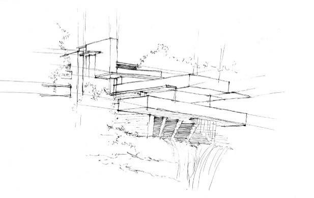
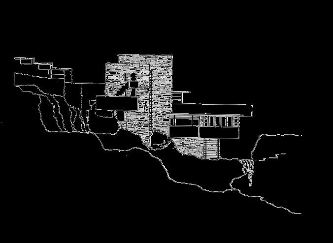
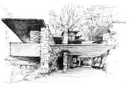
Similarly, bus terminal requires long span structure for different purposes like in berth area and as a sun shading devices, exposing the true nature of the structural member is one of the method of respecting the nature.
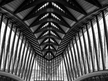
INTER – CITY BUS TERMINAL AT BANEPA Aakash Bhochhibhoya 160
Figure 7-1 : Frank Lloyd Wright's Falling Water
Figure 7-2 : Santiago Calatrava's Lyon-Satolas TGV Station
7.3. DEVELOPMENT OF MASTERPLAN AND FORM
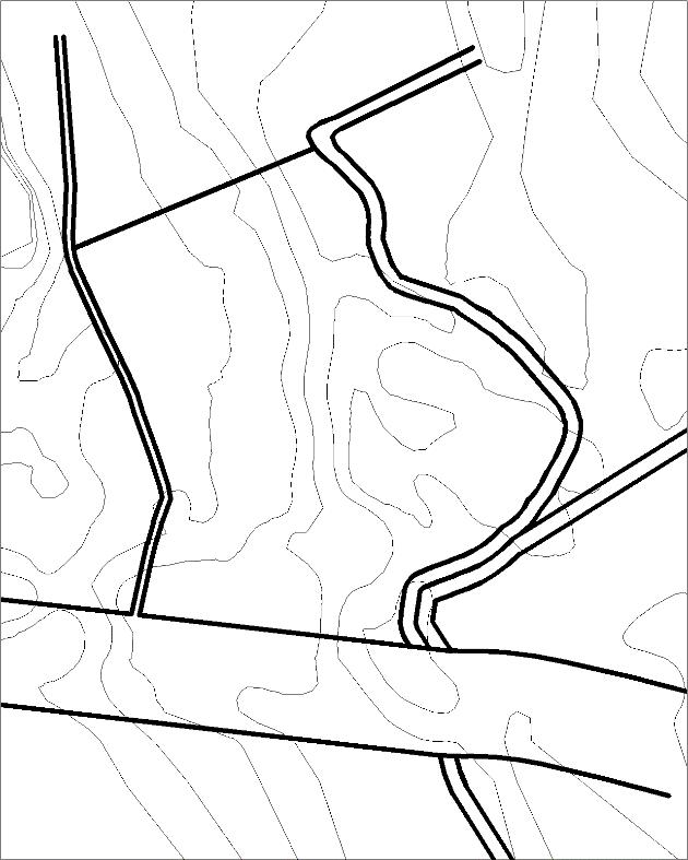
7.3.1. SITE DEVELOPMENT
Design of “Bus Terminal” is based on the site constrains and its opportunity. Since, circulation of bus needs more space for turning, the site with negligible contour land is chosen for minimizing the cost for cut and fill.
Division of land into private, semi-public and public space in the site. Maintaining the privacy of the space along with the Highway.
Semi-Public Space Private Space
Segregation of spaces is implemented in both horizontal and vertical manner.
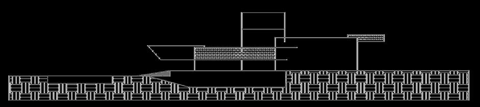
INTER – CITY BUS TERMINAL AT BANEPA Aakash Bhochhibhoya 161
SITE RIVER
HIGHWAY
Figure 7-3 : Landform of the site HIGHWAY Public Space
SITE
Figure 7-4 : Site Section
Figure 7-5 : Vertical segregation of space
HIGHWAY Public Space
Semi-Public Space Private Space
Ground floor is the place where mass number of people circulate so, the Public space is demarcated at ground level and road level. As the vertical height is obtained, more private function is carried out.
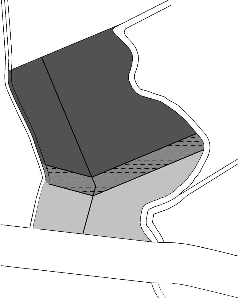
Private Space
Semi-Public Space
Public Space
7.3.2. ZONING
Public zone is designed near to the entrance. This zone comprises of entrance plaza, parking, guard unit, reception unit, administration, ticket counter, retail shops, waiting hall and cafeteria.
Semi-public zone comprises of the sectors which are used by both end users and outsiders (staff and members of the terminal). It comprises of medical unit, baggage screening area, dispensary unit, waiting lounge, arrival and departure berth.
Private space is placed at highest and end sector to give sense of freedom to the inmates. It comprises of file storage, baggage room, executive office, drivers room, passenger’s accommodation, workshop, fuel station, mechanical room, fire-fighting office, security office, water tank and long term parking of buses.
The whole zoning seems as segregation of spaces but yet designing does not reflect the direct segregation of various spaces but integration of different zones through pathways, bridge and semi open spaces.
INTER – CITY BUS TERMINAL AT BANEPA
Aakash Bhochhibhoya 162
HIGHWAY
Figure 7-6 : Horizontal segregation of space
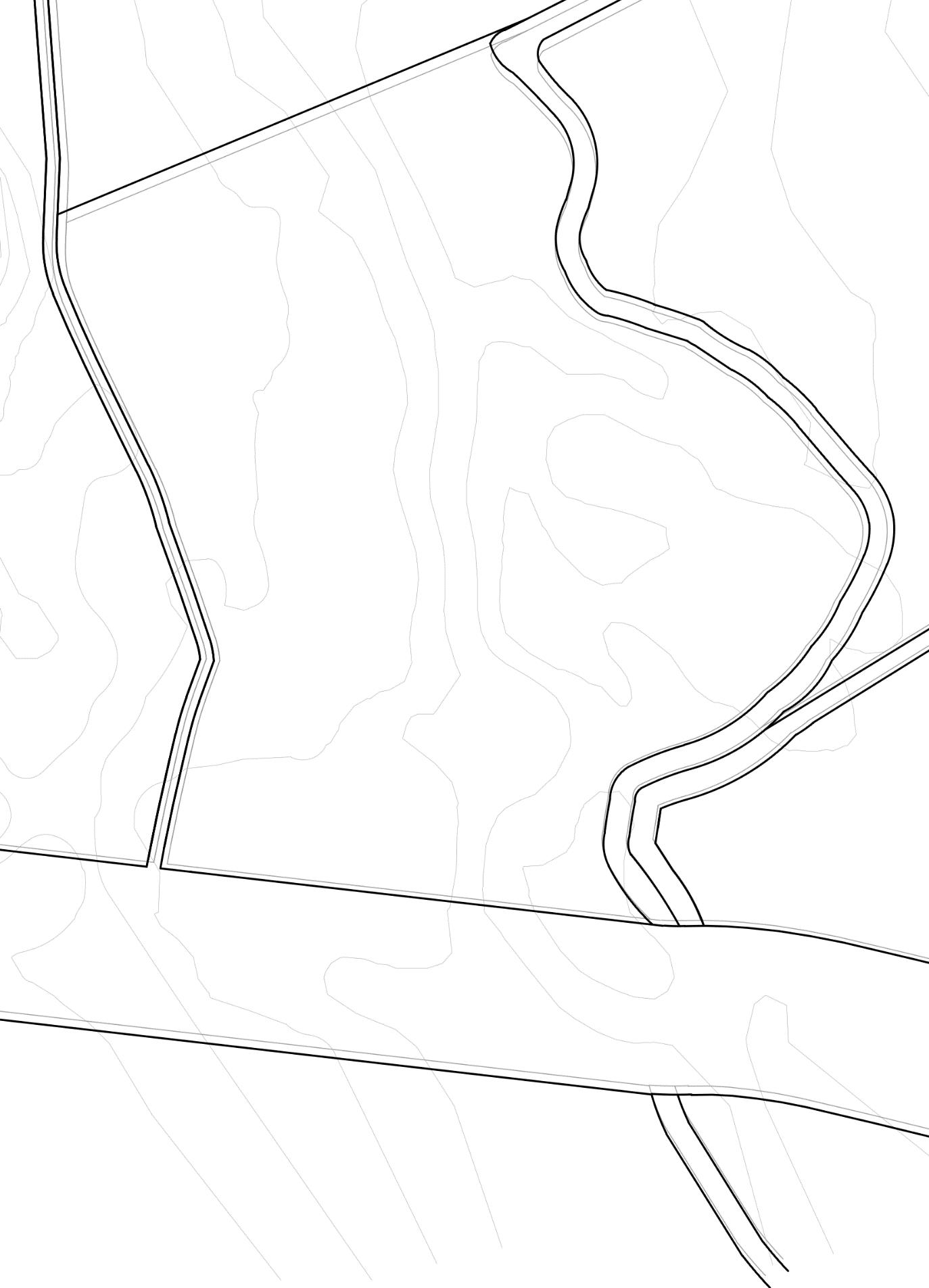

INTER – CITY BUS TERMINAL AT BANEPA Aakash Bhochhibhoya 163 S.N. SPACES 1 Entry bus 2 Entry private vehicles 3 Pedestrian + Plaza 4 Ticket counter office 5 Convenience store 6 Rental shops 7 Arrival berth 8 Private parking S.N. SPACES 9 Baggage room 10 Departure berth 11 Eatery 12 Fuel station 13 Ideal parking bus 14 Fire fighting 15 Workshop 16 Exit bus 16 1 8 2 3 7 18 5 4 9 11 14 13 15
7.3.3. ARCHITECTURAL DESIGN CONCEPT


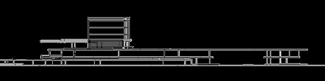
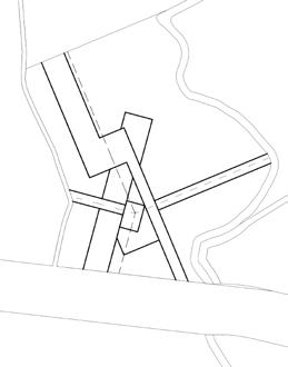
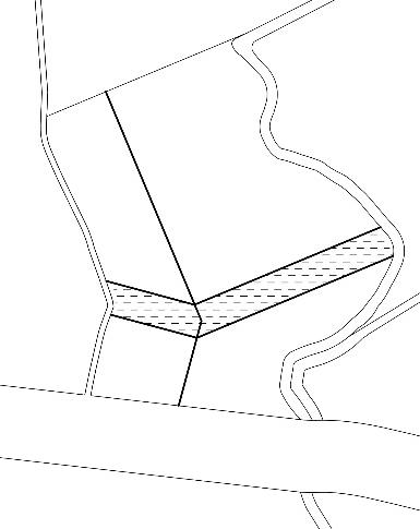
- FORM FOLLOWS SITE AND MOVEMENT with mutual relation
Similarly, mass of the block should also respect the site and its surrounding environment.
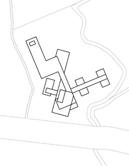
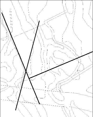
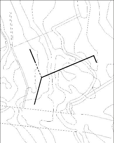
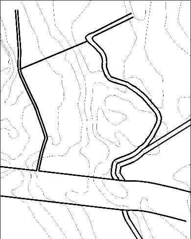
1) Massive block standing in the site does not reflects respecting the site. The process blocks the ground water recharge and true nature of ground
2) Lifting the block in piloties helps to breathe the ground and cools the surrounding environment.
3) For natural ventilation inside the block, puncturing the massive block. Since, mass number of people visit inside the terminal building, proper natural ventilation helps in sustainable design.
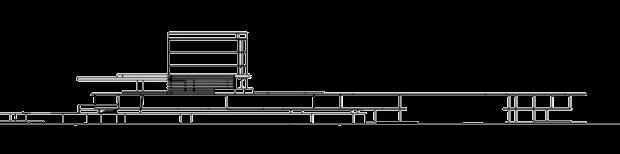
INTER – CITY BUS TERMINAL AT BANEPA Aakash Bhochhibhoya 164
1) Study of the site and its surrounding environment
2) Reference lines from the site boundary and shape
3) Movement of bus along reference lines without hampering pedestrian
4) Separating zones along reference lines
5) Adding functions along reference lines
5) Finalize conceptual master plan which fits in site
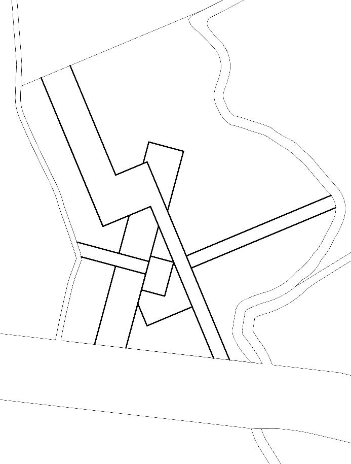
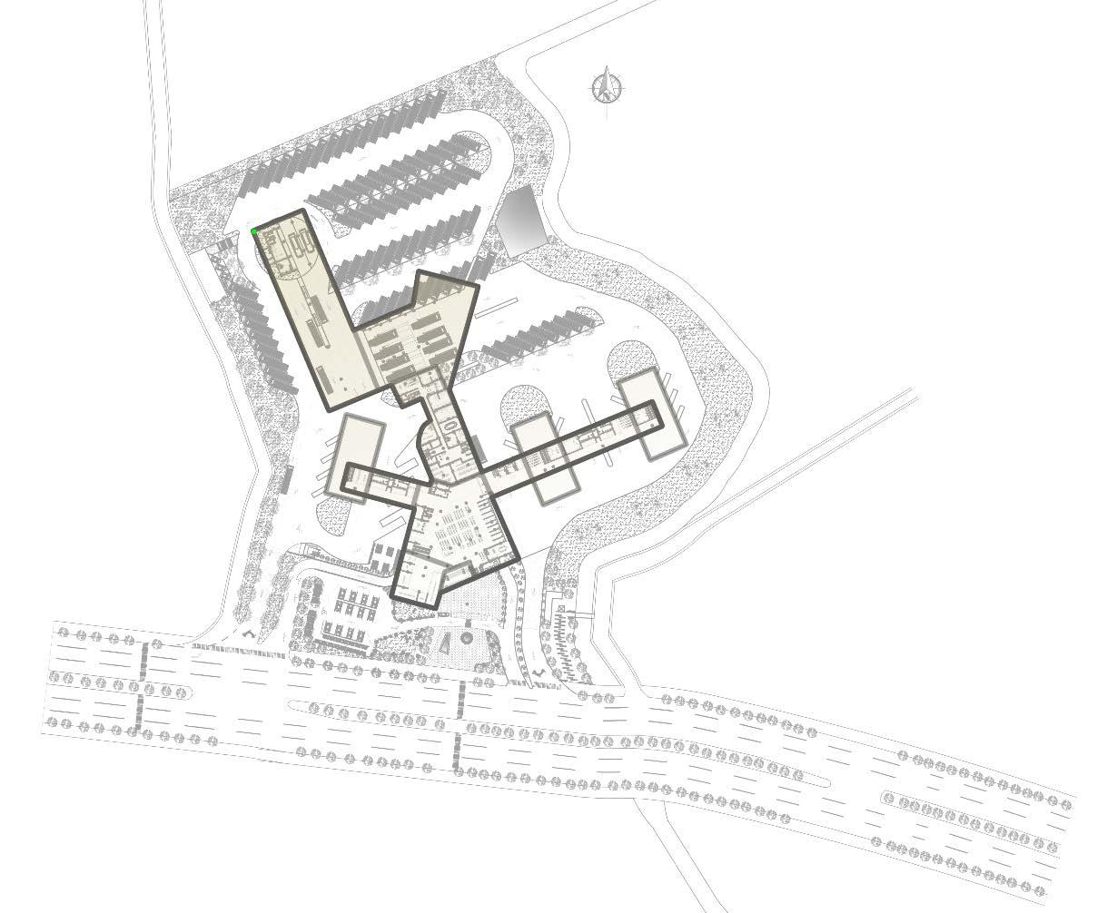


INTER – CITY BUS TERMINAL AT BANEPA Aakash Bhochhibhoya 165
Figure 7-7 : Zoning of the site
plaza
terminal
Figure 7-8 : Zoning incorporated with final master plan of bus terminal Refer annex for detail plans
Accommodation
Accommodation
Accommodation
Office + Cafeteria
Waiting area
Commercial + Terminal


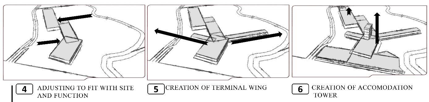
Waiting area
Parking Bus bay Bus bay
CREATION OF LONG SPAN SHADES
Which are truth to material (Steel and concrete)
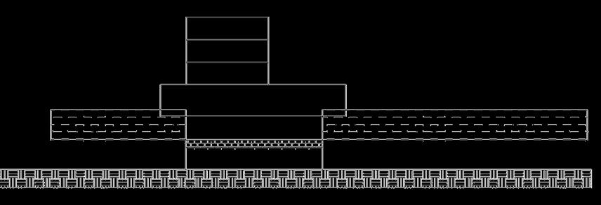
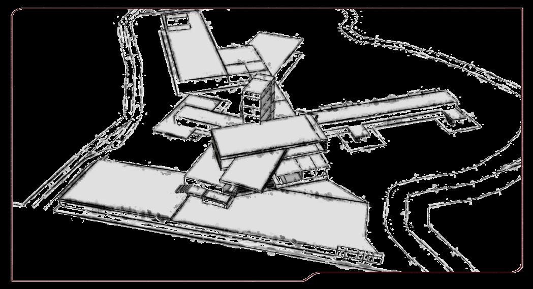
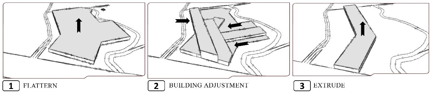
INTER – CITY BUS TERMINAL AT BANEPA Aakash Bhochhibhoya 166 - FOR VOLUME / FORM
7
Figure 7-9 : Conceptual section showing the functions accordingly from lower level to the upper level
7.4. DESIGN FEATURES AND SUMMARY
Refer annex for detail drawings
Circulation is first important aspect in bus terminal.
Separate entry and exit to achieve a better vehicular circulation.
Designing the pedestrian circulation in order to have maximum contact with commercial areas in the arrival and departure movement of people.
Arrival berth
Driver’s rest room
Departure berth, waiting area, lounge
Baggage screening
Waiting area, ticket counter, administration office
Arrival and departure for local buses
Commercial area near waiting area
Taxi and bicycle parking
Pick and drop zone
Entry plaza
Refer annex for detail drawing


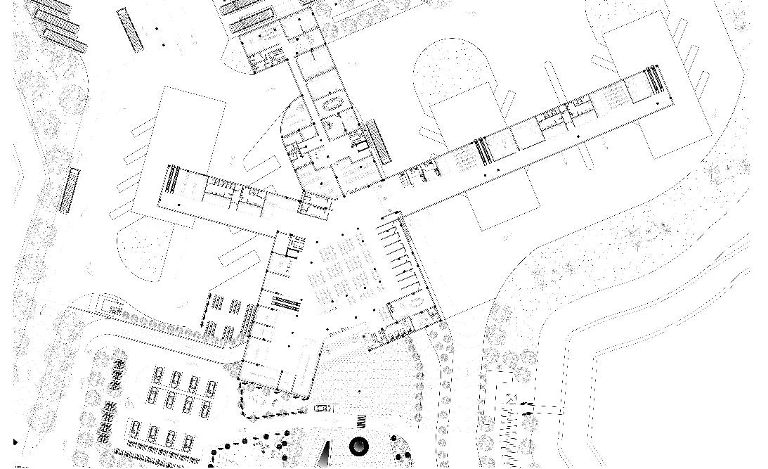
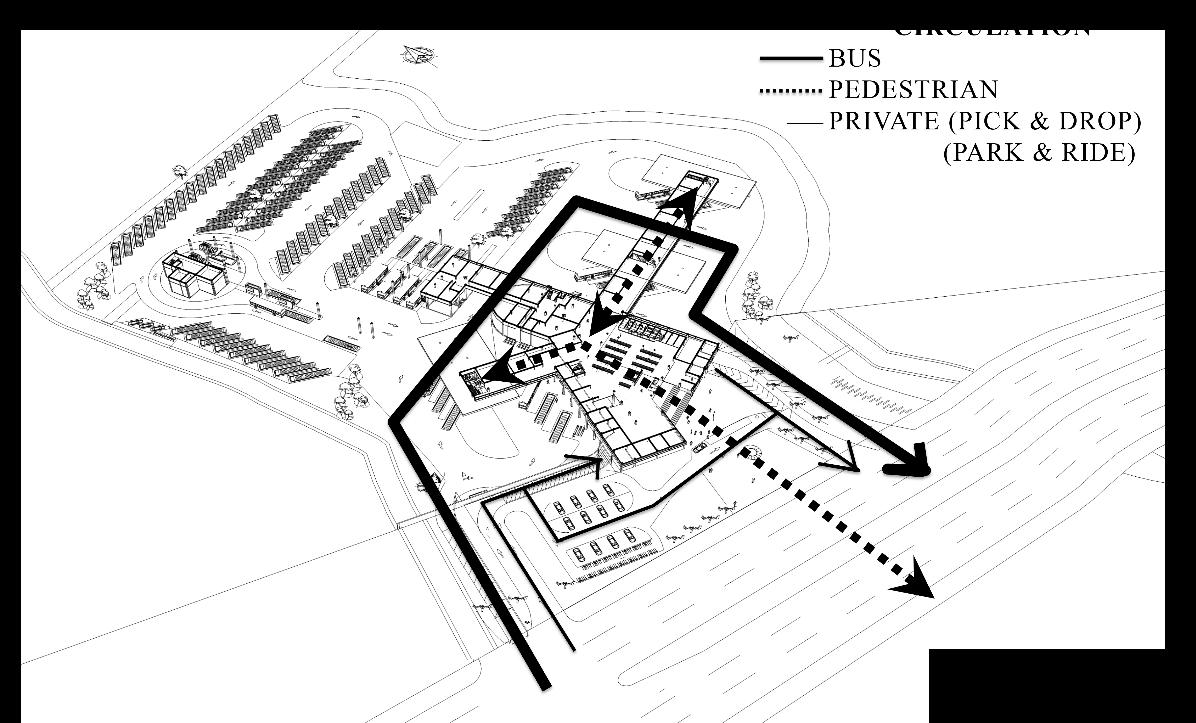
INTER – CITY BUS TERMINAL AT BANEPA
Bhochhibhoya
Aakash
167
Figure 7-10 : Circulation around the site
Figure 7-11 : Ground floor plan, terminal zone
Use of vertical band as elevation treatment to show the continuity in overall building


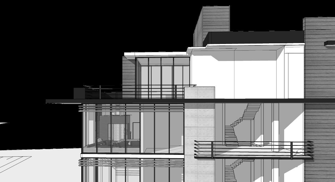


Common outdoor space in every floor in accommodation tower
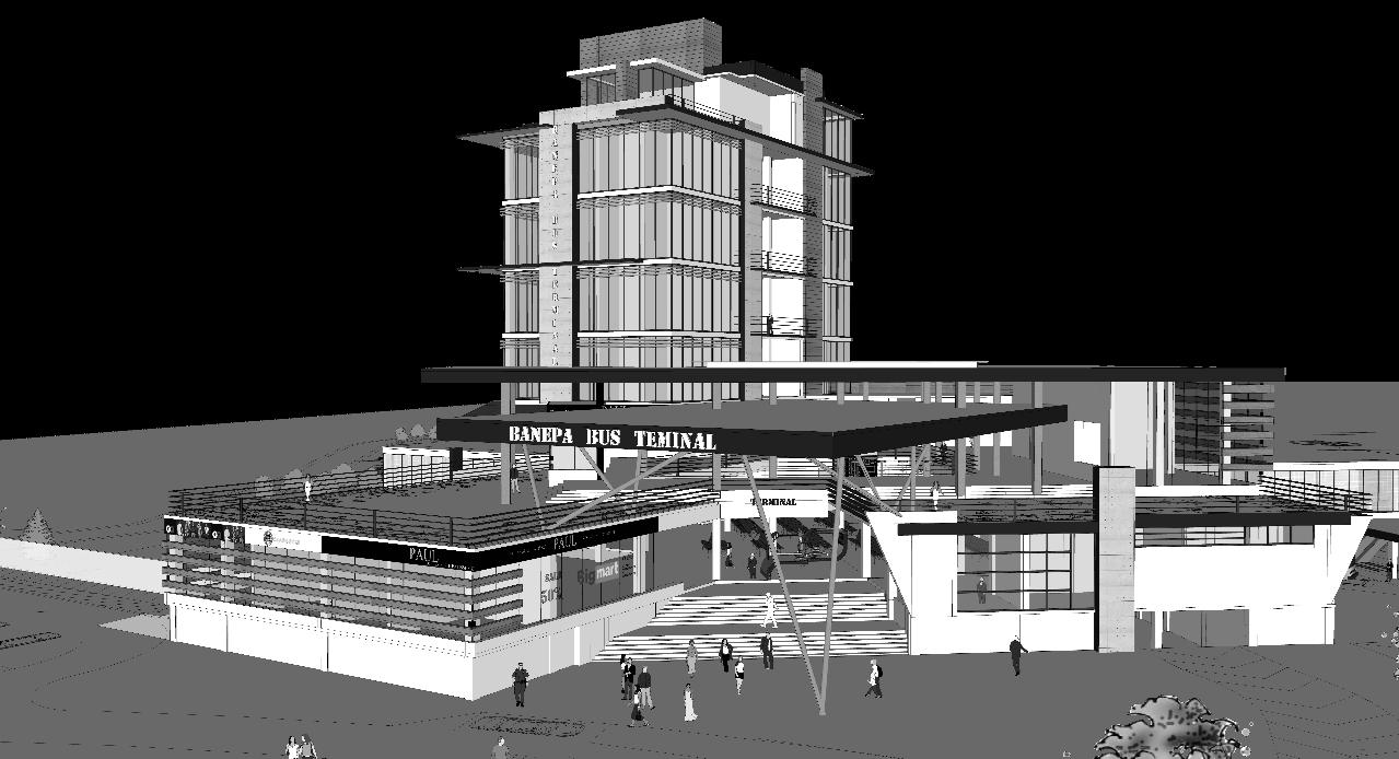
INTER – CITY BUS TERMINAL AT BANEPA Aakash Bhochhibhoya 168
: From view from highway
Double storey entrance with steps for clear welcoming space and free flow of natural air flow.
: View of accommodation tower
Figure 7-14 : Plan of accommodation area
as interactive space. Refer annex for detail drawings
Openings
INTER – CITY BUS TERMINAL AT BANEPA Aakash Bhochhibhoya 169 CHAPTER 8 SERVICES
8. BUILDING SERVICES
Building service is also one of the important portion of the design, it comprises of services that are used in day to day life as well as services used for emergency purpose.
8.1. WATER SERVICES
Before designing the pipeline layout, it is necessary to calculate the water requirement (liter/capital/day) of each building unit depending upon the number of users and type of building.
Calculation for water requirement (liter/capital/day)
Average number of daily users (N) = 3,000 Table 8-1 : Water demand calculation
Total water consumed = 2, 25,000 liters/day = 225 cubic meter
Then,
Storage tank requirement is calculated, which is shown below:
Capacity of storage tank,
Capacity of Ground storage Tank (minimum) = ½ to 1 day water demand
And,
Capacity of overhead storage tank, = 50 cubic meter x 5 times pumping = 5 x 4 x 2.5 cubic meter of overhead water tank
After determining water requirement, pipe size calculation is done that is shown below:-
Therefore, size of pipe for sink and toilet = 1/2"
Therefore, size of pipe for shower = 3/4"
INTER – CITY BUS TERMINAL AT BANEPA Aakash Bhochhibhoya 170
FUNCTION NO. OF PEOPLE LPCD ACCORDING TO BUILDING CODE DEMAND IN LIT. Terminal purpose 3,000 45 1,35,000 Commercial purpose 1,000 40 40,000 Office (unclassified) (residential) 5 8 500 – 1000 lit/day 65 5,000 520 Accommodation 64 200 lit/bed/day 12,800 Restaurant / Tea stall 250 50 12,500 First aid room 5 500 lit/bed/day 2,500 Utility room 16,680 TOTAL 2,25,000
8.2. SANITATION
In sanitation, waste water disposal has to be managed, reed bed plant is used to utilize grey water which is then used in vegetation. Black water is send to septic tank then to treatment plant and to reed bed then, to the river. Waste water pipe size is then calculated and sizes are:-
Water closet = 4"
Floor drain= 3"
Kitchen sink = 2"
Laundry tub = 1.5"
Shower = 2"
(
Reference: www.busde.paho.org/texcom/desastres/oxfamstg.pdf)
8.2.1. SIZE OF SEPTIC TANK
As per IS-2470, for 100 users, Length of septic tank (L) = 8 m
Breadth of the septic tank (B) = 2.8 m
Liquid Depth (D) = 1.04 m
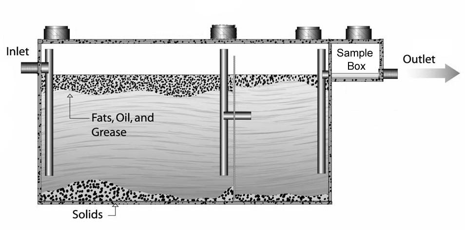
Volume (V) = L * B * D = 23.3 cubic meter
Free board depth = 0.45 m
Cleaning interval = 1 year
8.2.2. GREASE WATER TREATMENT
The maintenance of vehicles in the bus terminal gives out huge amount of grease water. This water is very harmful for the aquatic animals and plants. Thus, is must be treated before draining it to river.
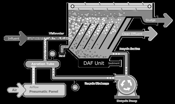
INTER – CITY BUS TERMINAL AT BANEPA Aakash Bhochhibhoya 171
Figure 8-1 : Section of Septic tank including Grease water treatment
Figure 8-2 : Grease water treatment detail
8.2.3. REED BED PLANT
Reed beds are part of a succession from young reed colonizing open water or wet ground through a gradation of increasingly dry ground. natural filtration process used in conjunction with a Bio safe Treatment Plant to further enhance the quality of effluent migrating into surrounding watercourse. The grey water is utilized for vegetation purpose. The actual inside dimensions of the reed bed will be 1200mm wide by 600mm deep by 7200mm long.
Typical size of reed bed is 1 m2/person, popular reed bed is Phragmites australis and slope of 1:100, gravel size is 3-10 mm and typical depth is 0.6 meter
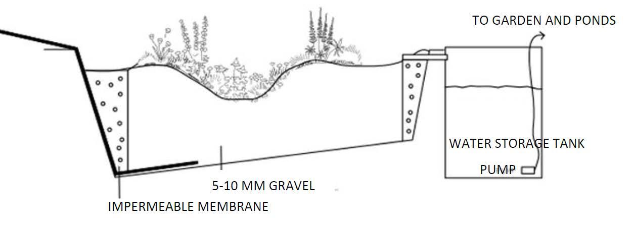
8.3. STORM WATER MANAGEMENT
The drainage system of the terminal complex needs to be good. No matter how good the drainage system is made, swamping will be caused during heavy rainfall. The way to eradicate the water lock problem in the area is to create a large number of small tanks which stores the excess storm water for the time being until the rest of the water flows through the narrow drain pipe. This method will help in reducing the swamp. The secondary surfaces are made to collect the storm water in the water catchment small tanks with plants on the surfaces.
Planter details
Dimensions;
Length = 18‘,
Width = 4‘
(Not including 6” wide perimeter curb)
Depth = approx.18”
From sidewalk grade to finish grade of planter max ponding depth = approx. 7”
INTER – CITY BUS TERMINAL AT BANEPA Aakash Bhochhibhoya 172
Figure 8-3 : Reed Bed plant
INTER – CITY BUS TERMINAL AT BANEPA Aakash Bhochhibhoya 173 CHAPTER 9 STRUCTURE
9. STRUCTURE 9.1. FOUNDATION
The type of foundation your building requires depends on many variables: soil type, building load, and environment to name a few. Sometimes the surface soil is very loose but below it is rock or very solid soil. Taller, heavier buildings require stronger foundations, while a shorter, wider building spreads the load over a larger patch of ground and can use a shallower foundation. Since, the function of building carries large number of live and dead loads, the foundation is designed the mat foundation.
A mat foundation, sometimes called a raft foundation, looks like it sounds. It is a “mat” of concrete that sits on or just below the ground; in other words, a shallow foundation. You may have heard it referred to as a slab foundation, a common choice for steel buildings.
Mat foundations are appropriate for light pre-engineered metal buildings with multi-span rigid frames and flexible walls. And they are suitable for building on poor soil (excluding peat and organics) that is uniform in consistency.
9.2. COLUMN


The Columns at the entrance are of steel tubular column of size 450 mm and angled at 150.
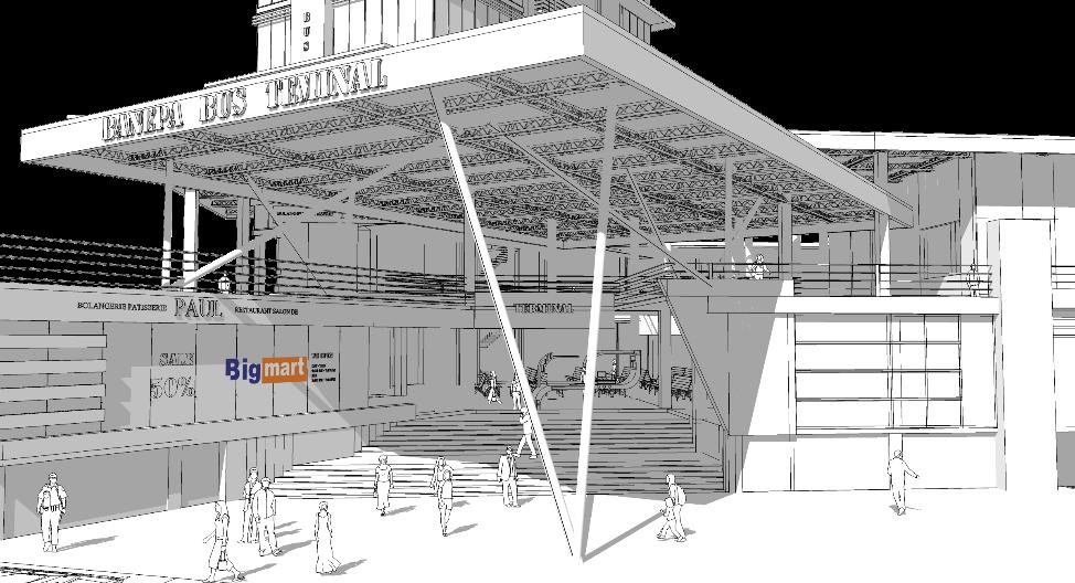
INTER – CITY BUS TERMINAL AT BANEPA Aakash Bhochhibhoya 174
Figure 9-1 : Section of mat foundation
Figure 9-3 : Entrance view
Figure 9-2 : Connection detail (Ball and socket joint)
9.3. WAFFLE SLAB
Waffle slabs are a reinforced concrete footing and slab system constructed on ground. They consist of a perimeter footing (edge beam) and a series of narrow internal beams (strip footings) at one meter nominal centers running each way.
9.4. TRUSS
The truss used is Steel lattice triangular truss, also known as Stage lighting triangular truss of 3 m in typical length.
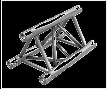
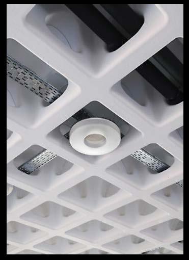
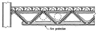
9.5. MULTI-STOREY LONG SPAN STRUCTURE
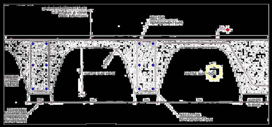
The type of multi-storey long span structure used is “Divided structural members” or composite truss.
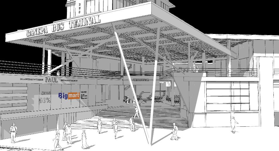
TYPE APPLICATION EXAMPLE
Divided structural members
Economic for spans >29 m
INTER – CITY BUS TERMINAL AT BANEPA Aakash Bhochhibhoya 175
Figure 9-4 : Waffle slab detail and lighting fixture
Figure 9-5 : Truss detail
From a structural point of view, the benefit of using a composite truss is due to the increase in stiffness rather than strength

9.6. EXPANSION JOINT
An expansion joint or movement joint is an assembly designed to safely absorb the heat-induced expansion and contraction of construction materials, to absorb vibration, to hold parts together, or to allow movement due to ground settlement or earthquakes.
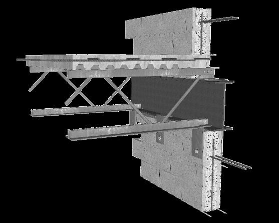
9.7. RETAINING WALL
Retaining walls are relatively rigid walls used for supporting the soil mass laterally so that the soil can be retained at different levels on the two sides. Retaining walls are structures designed to restrain soil to a slope that it would not naturally keep to (typically a steep, near-vertical or vertical slope).
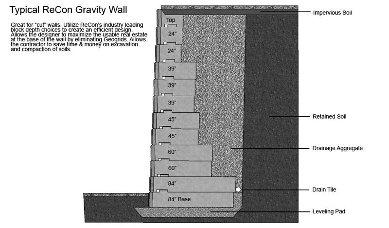
INTER – CITY BUS TERMINAL AT BANEPA Aakash Bhochhibhoya 176
Figure 9-6 : Multi-storey long span structure detail
Figure 9-7 : Expansion joint detail
Figure 9-8 : Retaining wall detail
INTER – CITY BUS TERMINAL AT BANEPA Aakash Bhochhibhoya 177
10 CIRCULATION
CHAPTER
10. CIRCULATION
For horizontal circulation, black-topped road, perforated concrete, flag stones and brick pavement are provided with long span steel lattice truss for shade and shadow. For vertical circulation, provision of ramps, stairs, lifts, escalators and bridge are provided.
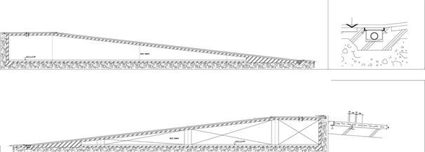
10.1. RAMP
Provision of ramp for both vehicular and pedestrian is designed. As the building is located at different level, ramps are given as specific place so that people can easily travel giving emphasis to universal design. Bus track is provided below 3 m height level and for that 1:10 ratio road track is provided as the vertical difference is more than 1.5 m.
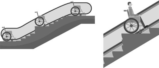
Ramp ratio for vehicle = 1: 10
Ramp ratio for pedestrian = 1: 12
10.2. STEPS
Steps are also provided for ease of travel from one contour land to another. 250mm of riser and 300 mm of tread are provided.
10.3. LIFTS
The lift well dimension is 3000 (depth) x 2200 (width) with entrance size 1200 mm which can carry 1360 Kg or 20 persons.
10.4. ESCALATORS
INTER – CITY BUS TERMINAL AT BANEPA Aakash Bhochhibhoya 178
Figure 10-1 : Ramp of road in ratio 1:10
Figure 10-2 : Wheel chair user accessible escalator at angle 300
SUSTAINABLE DESIGN
INTER – CITY BUS TERMINAL AT BANEPA Aakash Bhochhibhoya 179
CHAPTER 11
11. APPROACH FOR SUSTAINABLE DESIGN
Since this project demands different functions, depending upon the type of services each building unit is designed. It is important for the terminal to be sustainable in case of function, energy and cost.
11.1. BUILDING ORIENTATION
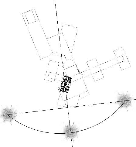
The building form is placed at angled from the east-west axis to maximize the south orientation. The waiting, entry plaza and accommodation are faced towards south to obtain light and natural ventilation in maximum flow of people. While, office area is faced towards north light to obtain diffused light for creating reading environment.
11.2. BUILT FORM
The overall master-plan is in respect to the site. The built form is a sustainable composition as:
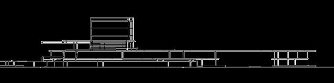
Clearing the ground coverage, rather than using the whole blocked building,
Shifting of masses and raising the building on piloties can help in the process of natural ventilation
Refreshing the entering air and cleaning the existing one
INTER – CITY BUS TERMINAL AT BANEPA Aakash Bhochhibhoya 180
Figure 11-1 : Building orientation
Figure 11-2 : Diagram of Built form
11.3. ROOF GARDENING
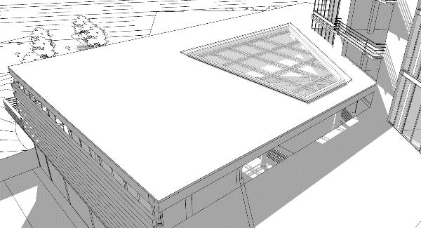
Roof gardening provides temperature control, hydrological benefits, architectural enhancement, habitats or corridors for recreational opportunities. Plants have the ability to reduce the overall heat absorption of the building which then reduces energy consumption. Species of grasses, alliums, herbs and wildflowers can thrive in 10 cm of growing medium.
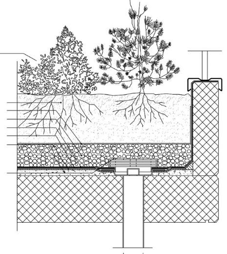
One of the most important components of the green roof system is the waterproofing/roof membrane. Typical wet soil weighs approximately 1,597 kg per cubic meter. The plant member including growing medium, drainage board, insulation board, waterproof membrane and concrete is 36”.
11.4. ATRIUM

The atrium is one of the generic strategies available in the quest to make the building more energyefficient and environmentally suitable. An atrium contributes to passive heating, is useful in overall ventilation and cooling strategies, and makes daylight available to the spaces which surround it. The atrium has allowed the innovative exploration of day-lighting by bringing natural light into the center of building, thus eliminating deep, dark spaces. Atrium can be thermally heavy due to high internal heat gains. Cooling requires a higher level of energy expenditure per degree of temperature reduction than does heating per degree of temperature increase.
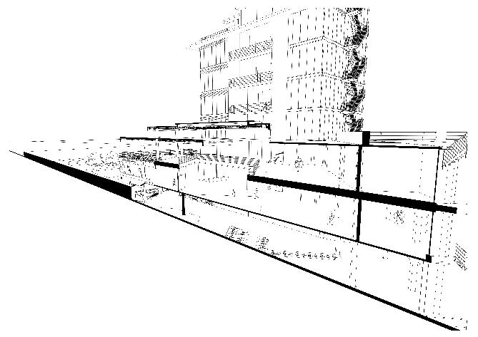
INTER – CITY BUS TERMINAL AT BANEPA Aakash Bhochhibhoya 181
PLANT MATERIAL SOIL DRAINAGE BOARD INSULATION BOARD WATERPROOF MEMBRANE CONCRETE
Figure 11-4 : Roof gardening
Figure 11-5 : Atrium to gain skylight in waiting area
Figure 11-3 : Perforated green roof for air flow in ideal parking
11.5. WALL AND WINDOW OPENINGS
The external wall needs to serve cold winters and hot summers. Horizontal Louver, Lamella window and sun shading device are used to provide light and shade effect on building. Opening are provided for light and ventilation as shown in the plan below:
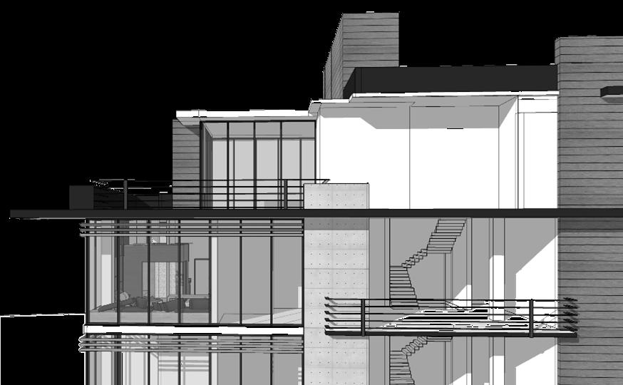
Opening
11.6. PASSIVE SHADING DEVICES
Solar shading is essential for all glazed walls facing the sun (generally south and west). A number of configurations of passive devices can be used depending upon façade orientation. Shading is designed to block solar radiation during hot summer days, thus helping to maintain constant indoor temperature. Use of vertical louver and pergolas for shading. The design incorporates locally available materials and sustainable features that respond to the specific constraints of climate. Vertical shading device is fixed to window, to provide shade and shadow effect.
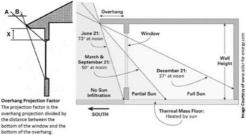
INTER – CITY BUS TERMINAL AT BANEPA Aakash Bhochhibhoya 182
Figure 11-6 : Exterior openings for light and ventilation
Horizontal shading device
Figure 11-7 : Courtesy of SBIC and the Beyond Green™ Guidelines for High-Performance Homes
11.7. RAIN WATER HARVESTING
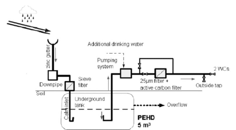
Rain water harvesting is a technique of collection and storage of rain water at surface or in subsurface aquifers, before it is lost as surface run-off. A system of harvesting rain water from the roof has been proposed and collected water is to be used for watering plants, in toilets and even for drinking after necessary treatments. The system includes catchments, conveyance system and storage tanks.
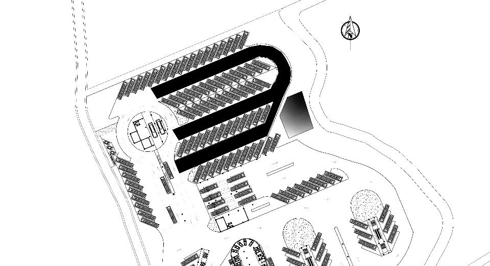
QUANTITY OF RAIN WATER COLLECTED (Q) = C * I * A
COEFFICIENT OF RAIN FALL (C) = 0.7
AVERAGE RAINFALL (I) = 0.1 m/hr. (FOR BANEPA)
CATCHMENT AREA (A) = 10,000 sq. m.
HENCE, Q = C * I * A = 0.7 * 0.1 * 10,000 = 700 cubic meter / hour
ASSUMING, 10 MINUTERS OF RAINFALL PER DAY,
QUANTITY OF RAINWATER COLLECTED = 116.6 CUBIC M / DAY
SIZE OF STORAGE TANK = 120 CUBIC METER = 20 * 13 * 5 = 1,300 CUBIC METER
Rain water is collected in a tank which is further filtered and used
INTER – CITY BUS TERMINAL AT BANEPA Aakash Bhochhibhoya 183
Figure 11-8 : Catchment area
Figure 11-9 : Rain water harvesting process
STORAGE FOR FIREFIGHTING AND WORKSHOP AREA
For firefighting, For above 15m in height but not exceeding 24m – 50,000 liter (2400 lit/min at pressure not less than 0.3 N/mm sq. (3kg/cm. sq ) at the top most hydrant)
For workshop, To wash the bus of 13 meter long, 100 – 120 liters of water is needed (Souce: Bitimic Srl) So, for workshop = 150 x 120 = 18,000 ltr.
Total demand = 50,000 + 18,000 = 68,000 + other demand ~ 1,00,000 ltr. = 100 cubic meter
11.8. BUILDING INTEGRATED PHOTOVOLTAIC

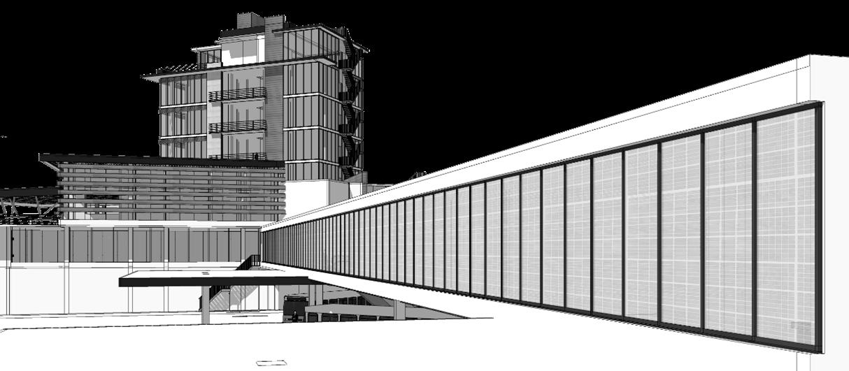
Building-integrated photovoltaic (BIPV) are photovoltaic materials that are used to replace conventional building materials in parts of the building envelope such as the roof, skylights, or facades. Flat roof is a thin film solar cell integrated to a flexible polymer roofing membrane. Solar panel is incorporated in pitched roof facing south.
It requires a lot of energy to run the public commercial buildings like bus terminal. So the solar energy consideration to certain extent can reduce the use of prevailing system of energy. And can help in reducing the economy in long term basis. The PV cells or panels are used to generate the current electricity through the sunlight. Individual solar cells are interconnected and encapsulated on various materials to form a module. Modules are strung together in an electrical series with cables and wires to form a PV array. The slope of the modules is 30˚ south. Direct or diffuse light shining on the solar cells induces the photovoltaic effect, generating unregulated DC electric power. This DC power is fed into an inverter that transforms and synchronizes the power into AC electricity.
INTER – CITY BUS TERMINAL AT BANEPA Aakash Bhochhibhoya 184
Figure 11-10 : Departure wing
Poly solar Panels (Transparent Solar Panel)
Calculations,
The total energy required by the building, (Assuming that 1m2 requires 0.05 kWh/day)
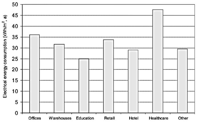
= 8586 x 0.05 KWh/day = 429.3 KWh/day
1 m2 of solar PV provides (65 W x 4.15 hrs. sunshine) = 0.27 kWh/day
And,
Total energy generated by solar PV (200m2) = 54 kWh/day
This is about 12.5% of the total energy required by the terminal building. About 77 modules of 0.99m x 2.63m each of 65W generating 0.27 KWh/day are required for this purpose.
Also, approx. 125 nos. of solar lights panels are provided in the passage area. And this will generate, 125 x 0.27 = 33.75 KWh/day
The lights in the parking area will only be used in the night time, And again the remaining solar power can be utilized by the terminal building.
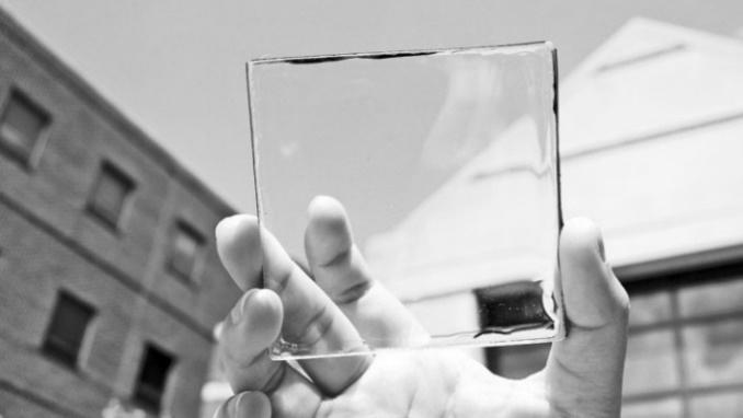
INTER – CITY BUS TERMINAL AT BANEPA Aakash Bhochhibhoya 185
Building Integrated Photovoltaic Electric System is an efficient way of using solar power which can be made more environmental friendly
Figure 11-11 : Electrical energy consumed per annum for different Buildings (Source: IEA 2006)
Figure 11-12 : Transparent solar panel prototype
11.9. CONSTRUCTION MATERIAL

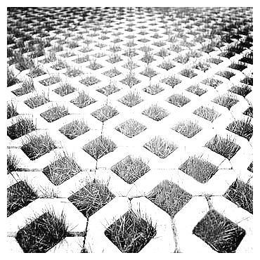
For maintaining sustainability, it is important to consider materials used in building construction. Use of environment friendly material is an important aspect of green design`. Brick is used as common construction material for exterior part of the building. Fly ash known as pulverized ash is to be used instead of cement in concrete. Fly ash is a waste product which require proper disposal so to ensure environment preservation besides increasing the durability of concrete, fly ash can be adopted.
Fly ash is used in brick, the brick made of 40% fly ash and 60% clay has been proposed as major construction material for walls. The use of fly ash in place of cement and clay thus saves as much as 30% of the cost of materials.
Use of lamella windows that provide shade and shadow effect beside openings. The design incorporates locally available materials and sustainable features that respond to the specific constraints of climate. Pratt truss is being used in gymnasium and multipurpose hall for creating larger span space.
11.10. GREENARY
As the site itself is surrounded by agricultural area and old settlement area, it is important to maintain greenery around and within the site. Concept of green design has been incorporated in this project, as a result green roof with recreational space is created. Along with the green roof, green wall partition has been used in parking space, likewise while designing pedestrian space, pavement is done in such a way that water table of the land is revived. Plants are actually good for the building and its occupants in a number of subtle ways and are an important element in providing a pleasant, tranquil environment where people can work or relax. If we are to look at green buildings or ecological buildings at its most fundamental level of understanding it is necessary to bring more greenery into them, and to balance the abiotic constituents with the biotic as with ecosystem in nature.
INTER – CITY BUS TERMINAL AT BANEPA Aakash Bhochhibhoya 186
Earth
Concrete pavers 80mm thick Aggregate in opening Curb edge restraint with cut out for overflow drainage
Perforated pipe sloped to drain
Figure 11-13 : Permeable pavers’ treatment
INTER – CITY BUS TERMINAL AT BANEPA Aakash Bhochhibhoya 187 CHAPTER 12 CONCLUSION
12. CONCLUSION
Thesis is one of the ideas between numbers of ideas, like there are number of ideas to catch the fish in water. The whole process of thesis has been really benefited as it has come across as a source to broaden the ideas and perspectives regarding the Architectural Analysis of space.
In overall, the work: is an endeavor to create an architecture that satisfies the functional and architectural expression of a bus terminal building, responses well to the context creating a better public realm and sense of place, and that goes well with systematic flow of passengers and vehicles. This thesis is a source of the ideas for the development of the Bus Terminal and development of the area as whole.
Regarding a Bus terminal my final words would be, ‘A bus terminal is a hub of different facilities whether it is commercial or it is of public need. It is a transit hub and therefore should address the needs of public, the context of city, and commercial happening going around, and should be flexible towards the future change and growth both in terms of capacity and architectural expressions.‟
INTER – CITY BUS TERMINAL AT BANEPA Aakash Bhochhibhoya 188
INTER – CITY BUS TERMINAL AT BANEPA Aakash Bhochhibhoya 189 CHAPTER 13 BIBLIOGRAPHY
13. BIBLIOGRAPHY
(n.d.). Retrieved from https://www.google.com.np/maps/place/GSRTC+Central+Bus+Depot/@23.0145339,72.5929 401,3a,75y,90t/data=!3m8!1e2!3m6!1sOvi7BKgaL04%2FV7RXwQi3QcI%2FAAAAAAAAAgA%2FCIqbNKjjO60BSYmGQRqW THFoYucgyjCjQCJkC!2e4!3e12!6s%2F%2Flh3.googleusercontent.com%2FOvi7BKgaL04%2
(n.d.). Retrieved from www.busde.paho.org/texcom/desastres/oxfamstg.pdf and Leitmann. (May 1996.). Innovative Urban Transportation in Curitiba A Successful Challenge to Conventional Wisdom. LACTD Regional Study, .
Baker, S. (2006). Sustainable development. Routledge,. London and New York.
Bus Stops - A Design Guide for Improved Quality,Translink and Roads Service. (1997). 10-18 Adelaide Street, Belfast.
Cervero, R. (n.d.). “Creating a Linear City with Surface Metro – the Story of Curitiba,” , . NTAC, Institute of Urban.
Chabet, B.-G. &. (1967). Encyclopedia. Retrieved from Encyclopedia: http://www.encyclopedia.com/education/dictionaries-thesauruses-pictures-and-pressreleases/satellite-town
Charles, T. (1964). The Shorter Oxford English Dictionary. Oxford: Oxford: Clarendon Press.
Childs, M. .. ((2010)). Spectrum of urban design roles.Journal of Urban Design,. Christopher Blow. (2005). Transport terminals and Modal Interchanges, planning &. Architectural Press & Publication.
Department of Roads. (2016, December 1). About Highways of Nepal. Retrieved from Department of Roads: https://www.dor.gov.np/national_highways.php
Garber, N. J. (2015). Trafiic and Highway Engineering. Lester A. Hoel.
GIDB IPTS Study (2000) by LBA. (2000). GIDB IPTS Study.
GIDB, GoG. (2015). Bus Rapid Transit System, Ahmedabad. In Bus Rapid Transit System, Ahmedabad (p. 83). Ahemdabad, India: AMC & AUDA.
GIDB/LB. (2000). Socio-Economic & Land use Studies. Ahmedabad.
GSTRC Gujarati and Hub Town. (2015). You Tube. Retrieved from https://www.youtube.com/watch?v=-E2qrwWGLCE
Hoque, M. M. (February 2016). Developing Satellite Towns. IACSIT International Journal of Engineering and Technology, Vol. 8, No. 1,, 51.
INTER – CITY BUS TERMINAL AT BANEPA Aakash Bhochhibhoya 190
India, T. o. (2015, May 11). "3-year-old abandoned at Geeta Mandir". Retrieved from Times of India: http://navbharattimes.indiatimes.com/
India, T. T. (13 January 2010. Retrieved 16 Oct 2011.). "Bus terminus chokes under rush". The Times of India. Chennai: The Times Group.
IPCC. (2014). IPCC(Intergovernmental panel on climate change). Retrieved from https://www.ipcc.ch/report/ar5/wg3/
J Rabinovitch and L. Leitmann. (n.d.). Environmental Innovation and Management in Curitiba, UNDP-UNCHS.
Jean - Paul Rodrigue. (1997). AN ASSESSMENT OF THE PROVISION OF FACILITIES AND SERVICES IN A TERMINAL FACILITY. A CASE OF MACHAKOS COUNTRY BUS TERMINAL.
Joseph Goodman, M. L. (2005/2006). Curitiba’s Bus System is Model for. race, poverty & the environment.
Lazar, R. (2002). Increasing Resources to Local Government in Ahmedabad, India. Local Strategies for Accelerating. ICLEI Study, Canada.
Ltd, U. C. (2015). GSRTC Busport Ahmedabad PPP Model - A Film by Unison Communications Pvt. Ltd. Ahmedabad - YouTube. Retrieved from https://www.youtube.com/watch?v=lviaUpuG7_o
Ltd., U. C. (2015). Changing Lives - New Face of bus travel experience in Gujarat @GeetaMandir Busport Ahmedabad. Retrieved from UNISON, Gujarat, INDIA. : http://www.unisoncom.com/
McDonough, W. a. (2000). The Hannover Principles Design for Sustainability. . Germany: The World’s Fair Hannover,.
Metrolinx. (2011). Mobility hub guidelines for the Greater Toronto and Hamilton areas. Retrieved from Ontario: Metrolinx, Government of Ontario: http://www.metrolinx.com/en/docs/pdf/board_
Mumford, E. (. (1937– 1969). Defining Urban Design: CIAM Architects and the Formation of a Discipline, . . New Haven, CT: Yale University Press.
News, S. (2015). New Bus Stand Inaugurated by CM Anandiben Patel in Ahmedabad Sandesh News - YouTube. Retrieved from You Tube: https://www.youtube.com/watch?v=PkNg-4r3BNA
NIUA. (2011). Peer experience and reflective learning (PEARL) under JnNURM. Retrieved from Urban Initiatives - Volume 4. New Delhi: NIUA: http://jnnurm.nic.in/wpcontent/uploads/2012/06/
oxforddictionaries. (2017). oxforddictionaries. Retrieved from https://www.oxforddictionaries.com/
PPIAF. (2016). Retrieved from https://ppiaf.org/documents/toolkits/UrbanBusToolkit/assets/3/3.1/35(vii)a.html
Rabinovitch and Hoehn. (1995).
INTER – CITY BUS TERMINAL AT BANEPA Aakash Bhochhibhoya 191
Rabinovitch, J. a. (1995). A Sustainable Urban Transportation System: the “Surface Metro” in Curitiba, Brazil.” The Environmental and Natural Resources Policy and Training Project. Michigan State University.
Rabinovitch, J. a. (1996) Urban Planning in Curitiba, A Brazilian City Challenges Conventional Wisdom and Relies on Low Technology to Improve the Quality of Urban Life. Scientific American.
Rabinovitch, J. (n.d.). Innovative Land Use and Transport Policy, The Case of Curitiba,, . Land Use Policy, Vol 13,.
Ranjan, S. (2015). Bus terminal library study.
Rasoonlimanesh et al. (2011). Sustainable urban development.
SAS.PLANET. (2016, 7 7). SAS.PLANET. Retrieved from http://www.sasgis.org/
site, C. C. (n.d.). Retrieved from - www.curitiba.pr.gov.br/inglis/solucoes/transporte.
STATE), G. (2015). BACKGROUND OF.
The World Bank. (2014).
Tirikatene, K. (2007). A framework for achieving high quality urban design, Auckland City Council. Working paper.
Town, H. (2015). Geeta Mandir Bus Port. Ahemdabad.
Tube, Y. (2015). Geeta Mandir Bus Port, GSRTC. Retrieved from https://www.youtube.com/watch?v=YXyQ1Tw58Vs
Tube, Y. (2015, Aug 6). Tv9 Gujarati. Retrieved from https://www.youtube.com/watch?v=KXl3GOcRNEY unescap. (2016). Retrieved from www.unescap.org
URBS. (n.d.). Curitiba Integrated Network, Urban Transportation World Reference. Curitiba. woodsbagot. (2017, Jan 10). Retrieved from http://woodsbagot.stealthtraffic.com/project/geetamandir-bus-terminals-ahmedabad-india
World Habitat Awards, B. a. (1996). Curitiba Urban Management, Building Full Citizenship.
Zaruch, L. (1975). Roteiro da Cidade, do bonde de mula ao onibus expresso. Curitiba, Paraná: Digital fotogravura Ltda.
Zhang, K. J. (2012). Nine Techniques for Enhancing Bus Stops and Neighbourhoods and their Application in Metro Vancouver.
INTER – CITY BUS TERMINAL AT BANEPA Aakash Bhochhibhoya 192

INTER – CITY BUS TERMINAL AT BANEPA Aakash Bhochhibhoya 193 CHAPTER 14 APPENDICES
