11 minute read
Examining Coil On Plug

from Auto Service Professional - August 2020
by EndeavorBusinessMedia-VehicleRepairGroup
The most reliable and durable ignition system to date By Jeff Taylor T Today’s modern ignition system normally will use a single ignition coil per cylinder, mounted directly or very close to the spark plug: the Coil On Plug (COP) design. Some systems use an individual coil and a small ignition wire in a Coil Near Plug (CNP) setup because the location of the spark plug in the cylinder head won’t allow enough room to directly mount a coil on the spark plug, I consider this a version of COP. COP ignition is the most reliable/durable ignition system that has been developed so go somewhere and it will find a path anyway that it can. These spikes can result in damage to the coil itself, the COP electronics and even the PCM. Worn out/incorrect/leaking spark plugs, carbon tracking, failed dielectric grease, excessive heat, moisture intrusion, oil from leaking gaskets and spark plug tubes, antifreeze contamination, and even dropping a COP unit during service can shorten the life of a COP unit. There is a long list of reasons that a COP far in the history of the automotive ignition can fail, but when it comes to diagnostics the systems, yet its function is still the same as it most common diagnostic approach is to swap was over 100 years ago: to create enough ena COP unit with one that was still working. I ergy to form a spark and ignite the air/fuel use this method, but with today’s engine packmixture, forcing the piston down. COP opaging and many COP units hidden under pleeration is Powertrain Control Module (PCM) nums and parts, a few simple tests at the COP controlled; improving the accuracy of spark connector will usually save time and help vertiming, coil dwell time, the number of sparks ify the issue before bolting it all back together. created per combustion event (multiple spark Identifying the type of COP system beevents are used by a number of manufacturing used is the first step in diagnostics and ers) and the amount of voltage that is available establishing a quick test routine for each to create the spark. type. Three types of COP ignition coils are COP’s reliability and durability doesn’t used commonly: the two-wire connector, the mean that it doesn’t fail. A failed or failing three-wire connector and the four-wire con
COP unit usually results in a customer comnector. Understanding how each of these COP plaint of rough running, stumbling or a Service system works can make the quick check part
Engine Soon light (SES). The first COP systems of our diagnostics a bit easier. Most of these had issues and many common pattern failures tests will require just a few simple tools and a (think early Ford V8 and Honda V6 COP igninon-factory scan tool. tion system). But there are a number of things that can cause a COP to fail. The most comThe two-wire COP ignition coil was common cause: open secondary or high secondary monly found on older Ford and Fiat Chrysler circuit resistance creating high voltage spikes. (FCA) products. The two- wire COP connector
The energy produced in the secondary has to will have a 12V power supply and a switching
signal. The two-wire COP design doesn’t have an integral ignition module. Most two-wire COP designs rely on the PCM (some use a remote mounted ignition module) to directly control dwell and timing to each COP unit by controlling the ground side of the circuit. The two-wire COP may use internal PCM electronics to detect the primary voltage spike created when the primary current flow is interrupted to confirm that the coil fired. An open or unplugged coil connector will set a P035x (x indicates the COP number) coil control circuit code. FCA (Fiat/Chrysler Automotive) PCMs monitor the primary pattern burn time and use this information to set coil ionization fault codes. If the PCM detects that the secondary ignition burn time is too short, incorrect, or not present, a code will set. Pay particular attention to the diagnostics as these “secondary circuit, insufficient ionization” codes don’t easily point to the correct COP assembly (i.e. P2308 code is for COP on cylinder 3).
Diagnosing and testing a two-wire COP can be done with a few tools: a spark tester and a self-powered test light (a scanner can be used if there is an SES light to point you to the COP culprit). 1. Always test for proper spark first. I use an
HEI tester. 2. If spark is missing then check for power (12V) at the two-wire COP connector with it disconnected. Remember that on an FCA product you will have to crank the engine to see 12V. If there isn’t 12V then you will have to refer to a wiring diagram. 3. If you have no spark but have 12V test the switching signal. Using a self-powered test light, crank the engine and watch the LED with the probe installed in the
COP connector. It should flash on and off. If it doesn’t flash, a wiring diagram and further testing will be required for diagnosis.
Open circuits on these older two-wire COP systems are common. I usually go straight to
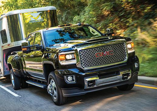
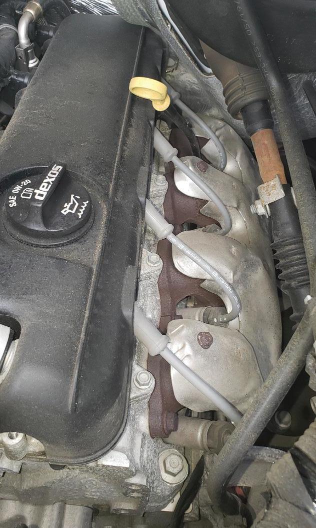
A 2017 GMC Sierra equipped with fourwire COP (Coil On Plug) coils under a decorative cover. Shown are the short wires that connect the coils to the spark plugs located between the exhaust ports. I consider this style to be a COP but it’s better described as CNP (Coil Near Plug).
the PCM connector check for switching, eliminating many connections. PCM failures are common on these older vehicles.
The three-wire COP ignition coil type is a popular COP design. The three-wire COP connector will have a 12V power supply, a ground and a PCM triggering circuit. The lack of any of these will result in no spark. On the threewire COP coil assembly, the ignition module or ignition control transistor is integral to the COP assembly. The PCM controls the ignition timing and dwell remotely using the triggering circuit. Most manufacturers will use a 5V trigger circuit, but some use 12V.
Primary voltage patterns and primary or secondary resistance values aren’t usually available due to internal electronics. Some manufactures have equipped their PCMs with the ability to detect and report an ignition problem by using the amplitude of the trigger pulse to detect if the circuit has gone open circuit or shorted. But it’s far more common for three-wire COP equipped vehicles to not monitor if an ignition event has occurred. They typically don’t set any COP related trouble codes if the COP connector has broken or open wiring or is completely disconnected. These vehicles will just set a misfire code but even that may take more than one road test.
Diagnosing and testing a three-wire COP can also be done quickly, using a spark tester, a DVOM and a scanner to pinpoint which COP is acting up. 1. Check for spark. 2. If there is no spark, check for power (12V) and a good ground. Many vehicles will feed power (12V) to a bank of COP coils via a dedicated fuse or relay and do simi-

FROM THE FIRST FILL TO THE PENTOSIN FLUIDS ARE DESIGNED TO LAST. MEET THE STRICT OE STANDARDS OF THE WORLD’S FINEST IMPORTS. CHECK OUT OUR FULL LINEUP OF HIGH-QUALITY FLUIDS AT PENTOSIN.NET OR VISIT OUR ONLINE CATALOG AT SHOWMETHEPARTS.COM/CRP.
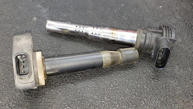
This is a three-wire Honda (left) and a four-wire VW/Audi COP.
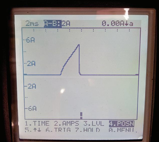
Current ramping is always an option in verifying COP functionality.
3. lar things with the ground circuit using splices to minimize wiring. If either the power or ground circuits are an issue, consult wiring diagrams to diagnose further, but if they are OK, look at the triggering circuit. Each triggering circuit is controlled individually by the PCM, so they will have a dedicated circuit that will go directly to the PCM. This triggering circuit needs to be tested with a DVOM capable of reading Hertz (Hz) or an oscilloscope. A test light will not work. To test the triggering circuit, reconnect the three-wire coil connector to the COP. Set the DVOM to Hz and carefully back probe the trigger wire on the COP connector. Connect the black DVOM lead to it and connect the red lead of the DVOM to battery voltage (12V) and then start the engine. You should see a fluctuating value (30 to 60Hz on a Honda V6). If there is no signal, a wiring diagram and further testing will be needed to verify the circuit’s integrity to the PCM.
The four-wire COP ignition coil type isn’t as popular as the three-wire COP but it is being used by major manufacturers in two variations. Toyota, Lexus and Mercedes-Benz use one format and General Motors uses another. Toyota and Mercedes use three of the four wires in the connector for power (12V), ground and a PCM-controlled trigger very similar to the three-wire COP, but the addition of a fourth wire provides feedback to the PCM that the coil has actually done what the PCM asked it to do. The Toyota version calls this fourth wire the ignition confirmation signal (IGF) and uses this signal to provide fail-safe fuel cut-off in the event that a coil has failed and isn’t firing the spark plug, protecting the catalytic convertor. The Toyota version provides a 5V bias signal on the IGF circuit that runs parallel to all the ignition coils.
Internal electronics in each COP monitor the coil operation and pulse the IGF to ground when the coil fires successfully. The PCM will recognize a lack of pulse and set a trouble code for the coil that failed to fire. Code P0351 “coil A primary/secondary circuit malfunction” for instance is telling you that coil “A” or the coil on #1 cylinder didn’t fire. Be careful when replacing Toyota coils with inexpensive or noname brands as they are known for having issues on the IGF circuit but will have spark when tested.
GM’s four-wire COP design has a power (12V) and ground circuit, a trigger circuit that GM refers to as Ignition Control (IC) and the fourth circuit wire is called “Reference Low.” This reference low wire is an auxiliary ground that is provided to the COP unit directly from the PCM. Its primary purpose is to provide a
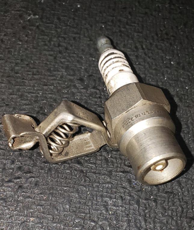
This is the spark tester that I have used for 30 years. It was designed to test the GM HEI ignition system and still works great to this day.
clean ground to the low current circuits and electronic in the COP while the other body ground is managing the coils’ primary coil current. If this reference low wire or circuit goes bad it is possible for the COP to use the other ground circuit to maintain functionality. GM’s IC trigger circuit is monitored by the PCM for opens and shorts to ground/power and uses a 5V signal to command COP operation and is quick to set trouble codes if it sees an issue on the IC line.
It’s worth noting that VW/Audi also uses a four-wire COP coil and similar to GM there is a 12V power, a 5V trigger and two grounds that both terminate on the cylinder head/cam cover. The power output stage uses one ground and the coil primary circuit uses a separate ground.
Diagnosing and testing the GM four-wire COP. 1. Check for spark. Start on the small ignition wire, as these COPs are actually CNP (coil near plug) setups. If there is no spark from the wire, I will go an extra step and put my spark tester into the coil with the spark plug wire removed to verify it’s a
COP issue and not a wire issue. 2. If there is no spark, check the connector for power 12V and proper ground. If either the power or ground circuits are an issue, then consult a wiring diagram to diagnose further. 3. Testing the reference low can be done with or without the connector connected.
Using DVOM, test the reference low by installing the red lead on battery positive and the black lead on reference low. The reading with key on/engine off should be 10V to 12V. 4. If all the circuits test OK to this point and there is still no spark, we need to check the IC wire. Using your DVOM and setting the meter to Hz back probe the IC circuit with the black meter probe and attach the red meter lead to battery positive. The Hz reading on the IC wire should be 5 Hz to 8 Hz with the engine running.
Understanding how each individual COP system works is essential for quick and accurate diagnostics.
Today’s COP ignition systems are robust and tend to fail mainly due to negligence or mechanical failures, but failures do occur. Proper routine maintenance of spark plugs and repairing fluid leaks is imperative to the durability of this system.
And don’t forget that good quality COP replacement parts are a must. ■
Jeff Taylor boasts a 33-year career in the automotive industry with Eccles Auto Service in Dundas, Ontario, as a fully licensed professional lead technician. While continuing to be “on the bench” every day, Jeff is also heavily involved in government focus groups, serves as an accomplished technical writer and has competed in international diagnostic competitions as well as providing his expertise as an automotive technical instructor for a major aftermarket parts retailer.
