10 minute read
Converter ‘failure’ is often caused by upstream or damage issues

from Auto Service Professional - July/August 2013
by EndeavorBusinessMedia-VehicleRepairGroup

can fail, but more often than not, the root cause might involve upstream components such as an O 2 sensor, fuel injectors, spark plugs, EGR valve system, exhausts manifolds, vacuum hoses and MAF sensors.
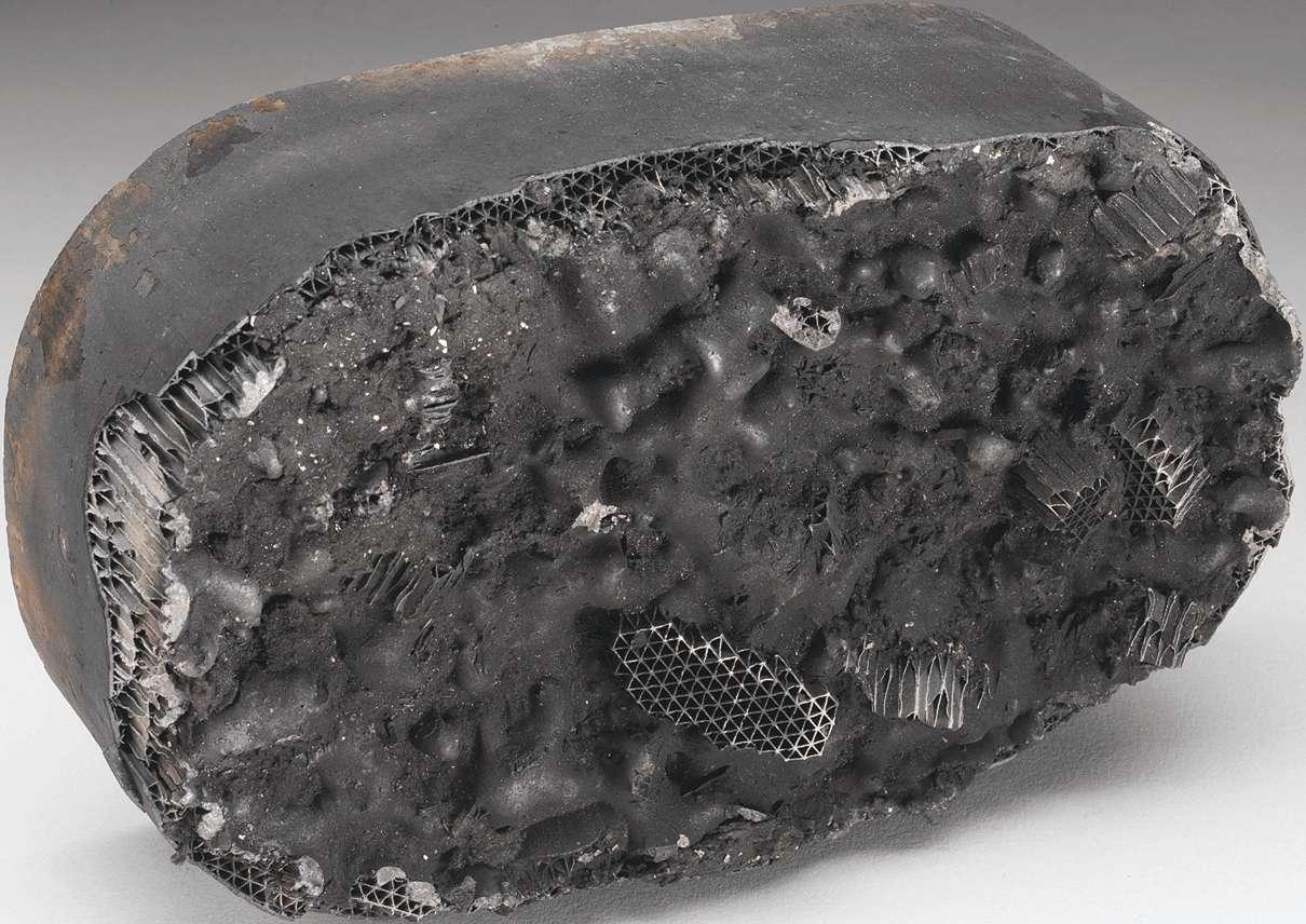
Thermal failures: Although modern three-way converters (TWC) can withstand short exposures to 2,000 degrees Fahrenheit, engine exhaust conditions caused by failed or out of tolerance parts can push temperatures above the converter’s operating limit. Excessive rich fuel conditions and exhaust leaks ahead of the converter are prime examples. They result in higher than normal temperatures that can cause matting erosion and burn away or melt converter coatings. If temperatures are high enough, the ceramic substrate itself will melt and clog.
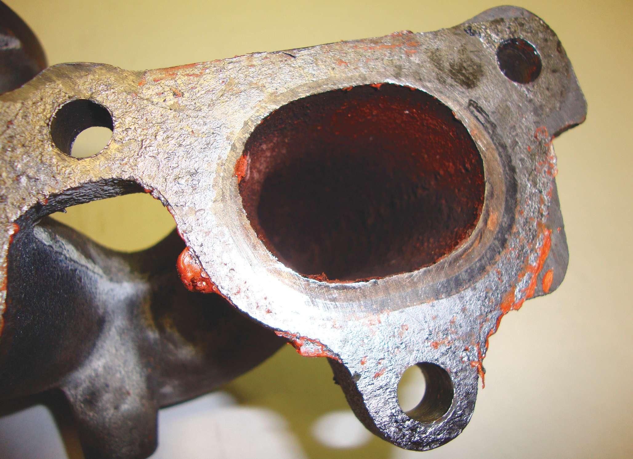
Contamination: If silicone products are used to seal any part of the exhaust system including the exhaust manifold and gaskets, O 2 sensors, and exhaust tubing, you’ve got problems. At best, the highest rated silicone can only handle 700 degrees F, so when exposed to exhaust temperatures of 1,200 degrees F, it quickly burns and outgases, leaving a silicone coating on the O 2 sensor or converter wash coating. The results include engine conditions that are out of operating range and reduced eff ciencies within the catalytic converter.
Coated or fouled: Anything that gets through the combustion chamber and reaches the face of the converter can reduce catalyst eff ciency. Liquids such as antifreeze from leaking manifolds and oil from head gasket failures top the list of troublemakers.
Engines in need of service and older engines that burn oil due to worn cylinder walls, stuck rings, and worn valve guides will produce by-products that can foul the converter.
Common causes of failure
Here are some illustrations of converter failures that should make you look
Engine running too hot.
Engine oil entering exhaust.
Impact under vehicle crushing converter.


elsewhere in the engine for the real cause of the problem.
Failures caused by these problems are not covered by the manufacturer’s warranty. Chasing P0420 codes
One of the most annoying challenges to emissions service has to be the persistent P0420 code. Although it typically points to a catalytic converter issue, it can just as easily be generated by a variety of engine problems not directly related to the converter. Possible “non-converter related” P0420 causes: • Intake manifold leaks • Fuel injector leakage • Wrong spark plugs • Incorrect ignition timing • EGR problem • Oil or antifreeze entering exhaust • O 2 sensor malfunction • Road damage to converter • RTV silicone contamination (re-use of improper volatile RTV)
Avoid silicone and Tef on contamination. In addition to incompatible RTV, siliconebased products or Tef on sealants can also generate a P0420 and should not be used on any part of the exhaust system. They cannot operate at high exhaust temperatures and will out-gas and damage the O 2 sensors.
When it comes to service issues on today’s vehicles, the diff culty in correctly diagnosing and evaluating catalytic converter problems has to be at top of the list.
One of the most annoying problems is the persistent P0420 diagnostic code (Catalyst System Eff ciency Below Threshold (Bank 1), which not only shows its teeth when the catalytic converter is on the blink, but can also be generated by a variety of engine problems not directly related to the
Incomplete combustion by-products.
converter.
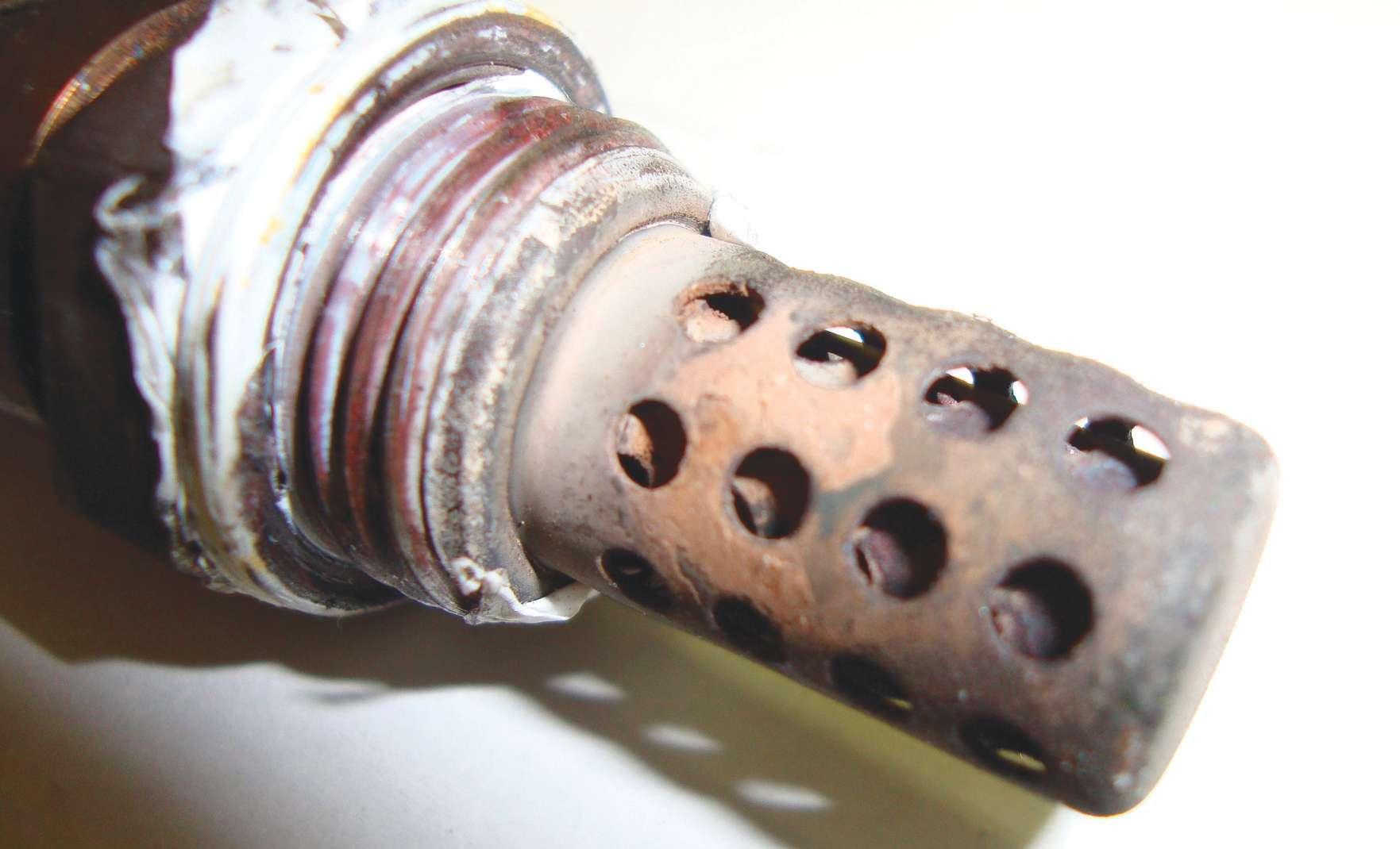
An O 2 sensor contaminated by Tef on tape.
Evidence of RTV on an exhaust manifold.
Possible P0420 code causes
The following engine related problems are known to generate the P0420 code:
• Intake manifold air leaks • Fuel injector problems (leaks) • Incorrect spark plugs • Ignition timing • EGR problem • Defective catalytic converter • Oil or antifreeze entering exhaust • O 2 sensor not operating correctly • Road damage to converter • Silicone contamination

Most, if not all, catalytic converter failures are caused by a problem or malfunction somewhere in the emission system ahead of the converter. So, it’s very important to determine what actually caused the converter to fail, so that the problem can be repaired and a recurrence can be prevented.
Here are some troubleshooting suggestions:
Method 1: Vacuum test
Connect a vacuum gauge to the vacuum on the intake manifold, carburetor, or throttle body. Note the reading at idle. Then raise and hold engine speed at 3,000 rpm. The needle will drop when you f rst open the throttle, but should then rise and level off. If the vacuum reading starts to drop, pressure may be backing up in the exhaust system indicating a blockage somewhere in the exhaust system.
Method 2: Backpressure test
Measure backpressure directly. If the vehicle’s engine has air injection, disconnect the check valve from the distribution manifold and connect a low pressure gauge. Or, remove the oxygen sensor and take your reading at its port in the manifold or head pipe. A reading of more than 1.25 psi at idle or more than 3 psi at 2,000 rpm tells you there’s an exhaust restriction.
Method 3: Temperature test
In late model engines with fuel injection, the combustion is so eff cient that the converter has little to process and the difference between the inlet and outlet temperatures may only be 50 degrees F at 2,500 rpm. This is a lot less than the old rule of thumb that says a good converter should show at least a 100 degrees F difference. At idle, the converter in many late-model vehicles may cool down so much that there’s almost no measurable difference between the front and back temperatures. So checking exhaust temperatures front and back of the converter at idle and 2,500 rpm may not be an accurate way to determine if the converter is working or not.
Watch out for contamination
Silicone-based products or Tef on sealants should not be used on any part of the exhaust system. They are not designed to operate at high exhaust temperatures and will outgas, causing damage to O 2 sensors. See page 20 for some examples of O 2 sensor


contamination caused by the use of RTV silicone on exhaust manifold f anges and other components as well as Tef on-type sealants used on O 2 sensors.
Fuel trim
If you are trying to diagnose driveability issues but don’t have any trouble codes to chase, take a closer look at the engine’s fuel trim. When analyzed properly, it can be a valuable diagnostic tool, serving as a window to the heart of the fuel management system.
Understanding fuel trim
A vehicle’s computer system uses fuel trim to help maintain the ideal air/fuel ratio for complete combustion (stoichiometry — 14.7 parts air to one part fuel). Three-way catalytic converters need the mixture to be constantly driven rich/lean around this ratio in order to work at maximum eff - ciency. Fuel trims can compensate for other vehicle issues. That’s why fuel trims are so useful. They can provide an overall picture of what is causing the problem such as an intake manifold vacuum leak (positive fuel trim — lean) or a stuck open fuel injector (negative fuel trim — rich).
Short-term fuel trim
Short-term fuel trim (STFT1 and STFT2) is the computer’s immediate response to adjust the air/fuel ratio. In positive corrections, fuel is added to adjust for a lean condition, while negative corrections respond to a rich condition. STFT corrections represent the current engine run cycle and react very quickly to O 2 sensor input. If you were to create a large vacuum leak at idle by disconnecting the PCV hose, the computer would immediately add positive fuel trim to balance the mixture. Short term fuel trim is not stored in Keep Alive Memory (KAM) after shut down and automatically resets to 0 for the next start/run cycle.
Long-term fuel trim
Unlike STFT, long-term fuel trim (LTFT1 and LTFT2) is learned over time while in closed loop operation. It is stored in the KAM and also used for open loop fuel calculations (like start up and wide open throttle). LTFT is a wider adjustment and also works to keep STFT within specif cation.
Diagnosing with fuel trims
Fuel trims can help you zero-in on the problem, especially when there are no other trouble codes present. Knowing whether an engine is running too rich or too lean will help narrow down your diagnosis. Fuel trims that differ greatly from one cylinder bank to the other will also point you in the right direction. Always evaluate fuel trims at idle and at 2,500 rpm.
Running too rich — High negative fuel trim corrections can be caused by MAF sensor problems, high fuel pressure, leaking fuel pressure regulator diaphragm, faulty evaporative emissions components, leaking injectors, defective O 2 sensors, exhaust leaks/pinholes before the O 2 sensor, coolant temp sensor problems, and base engine issues such as low compression and incorrect camshaft timing.
Running too lean — High positive fuel corrections can be traced to MAF and O2 sensor faults, vacuum leaks from intake gaskets/hoses, un-metered air (such as an intake snorkel leak), clogged or dirty fuel injectors, fuel delivery issues, and exhaust restrictions such as a clogged catalytic converter.
Here’s a diagnostic tip: For a suspected vacuum leak, note the fuel trims at idle and increase engine speed to 2,500 rpm and hold. If the STFT immediately decreases and moves to acceptable levels and the LTFT slowly starts to come back down, you have a vacuum leak.
After the repair, reset the KAM and start the engine. Monitor the fuel trims to make sure they are within the normal ranges. Achieving an accurate LTFT reading may require as much as 10 miles of driving.
Catalytic converter break-in
That’s right — a replacement catalytic converter needs a proper “break-in” period, just like a new engine or a set of new brake pads. This will ensure that the cat will continue to work the way it is supposed to and deliver the required emissions reliability and long service life. If the converter is not warmed-up (broken-in) properly, the substrate inside could be adversely affected and eventually cause the converter to fail down the road.
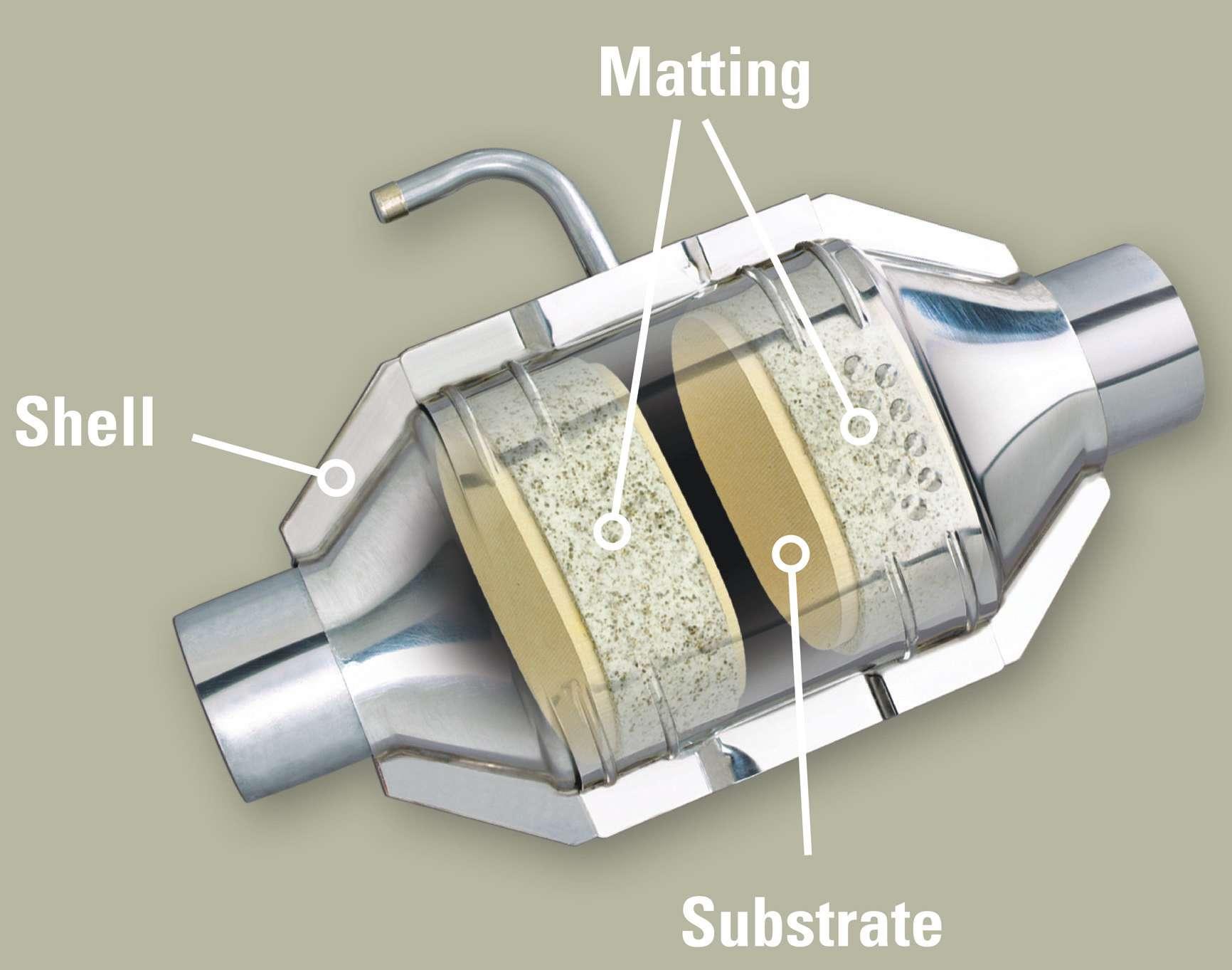
The problem typically occurs when a shop installs the converter and immediately returns the vehicle to the customer. The customer drives away and runs the car for a long distance or lets the vehicle idle for an extended period of time. Under these conditions, the matting, which is intended to secure the substrate, will not expand properly and hold it in place.
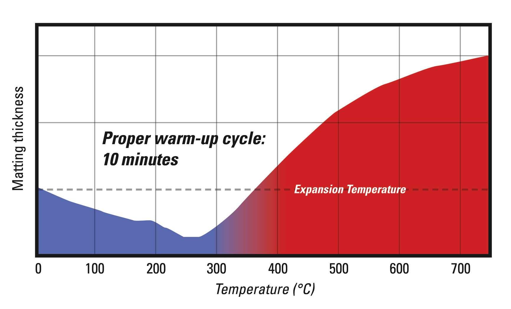
Converter matting is made from a mineral called vermiculite, which is held together by a f ber mat and an organic binder. This matting is wrapped around the converter’s ceramic brick (see art on page 20).
The matting is installed in the converter in an unexpanded state. During the f rst heat-up, the f ber mat and binder burn off and the matting actually gets looser before it expands to f ll the converter cavity to hold the ceramic brick in place (see graph below).
If that warm-up is not done properly, the brick can come loose and get damaged.
That rattle you might hear inside the converter shell is a sure telltale sign for this problem.
Warm up the cat
The best way to avoid this service issue and potential warranty problems is to include the warm-up period as a key part of your overall converter installation procedure. This heating cycle will allow for correct matting expansion.
Converter break-in tips • Start the engine but do not rev the engine. • Idle the engine and allow it to warm up slowly. • After f ve minutes, increase the engine speed to 2,500 rpm. • Hold at 2,500 rpm for two minutes. • Allow the engine to cool down. • Road test to conf rm correct installation. ●