13 minute read
How can I know if it’s really the module?2

from Auto Service Professional - July/August 2013
by EndeavorBusinessMedia-VehicleRepairGroup

PCM module diagnostics
How can I know if it’s really the module?
By Alex Portillo
Vehicle diagnosed by Kevin Quinlan.
How long do most diagnostics take you? Maybe an hour? A diagnostic procedure that can be completed that quickly is usually pretty cut and dried, such as a bad sensor or vacuum leak. When diagnostics start taking longer and the problem seems to continue after we change common failure components, we start suspecting a bad module.
When a module arouses suspicion, you start to doubt yourself. Is it really the module or did you miss something? Modules are expensive, they cannot be returned, and on the late model vehicles they cannot be swapped without being reprogrammed or sometimes not swapped at all!
The stakes are very high when diagnosing a module, but there is a way you can diagnose a module with 100% conf dence. There are not that many steps, because diagnosing a module employs simple logic.
Here are the steps to diagnose any module when you have a DTC:
1. Check TSBs to see if there are any software updates, extended warranties for defective modules, or other good diagnostic information that indicates you need to
Figure 1. Early Jeep Libertys can burn the PCM as a result of simply f lling the gas tank due to possible static. A ground strap needs to be added to the f ll neck to prevent static electricity.
Figure 2. Where do we begin with our diagnosis? The author notes that the Snap-on Modis was the f rst scan tool that provided fuel lever sender voltage.

replace a module. (DO NOT SKIP THIS STEP! Follow Step 1 f rst before wasting your time taking needless measurements or replacing any components.) 2. Diagnose and repair any bad sensors or actuators that may be responsible for the DTC. (This is very time consuming, but necessary.) 3. When all measurements and components are good, look for illogical PID data or vehicle conditions given the sensor feedback.
You don’t need to be Socrates or Spock to understand logic. Logic is simple and absolutely necessary when diagnosing modules. Why? Because when the car does things that are the opposite of what you expect, it is only natural to become overwhelmed and want to start guessing. Don’t start guessing! Let yourself be informed by your diagnostics.
On a vehicle, we must make our decisions based upon solid evidence that tests on a vehicle will provide us. We’re going to cover our three step module diagnostic process using a case study so we can learn how to be conf dent of how to diagnose modules.
2002 Jeep Liberty 3.7L with wrong fuel level reading
We had a 2002 Jeep Liberty in our shop and the problem with the vehicle was that its fuel gauge went onto the empty indicator remarkably soon (see Figure 1).
Also, the instrument cluster displays for the vehicle’s four-wheel-drive system worked backwards. For example, twowheel-drive was engaged when 4-HI was illuminated and vice versa.
We had some decent information from the customer to work with. First, f lling up the vehicle with gas right after the indicator hit “empty” resulted in taking only nine gallons of gas in an 18-gallon tank. Also, we knew that the fuel level sender unit was replaced.
So, we know that there is def nitely a
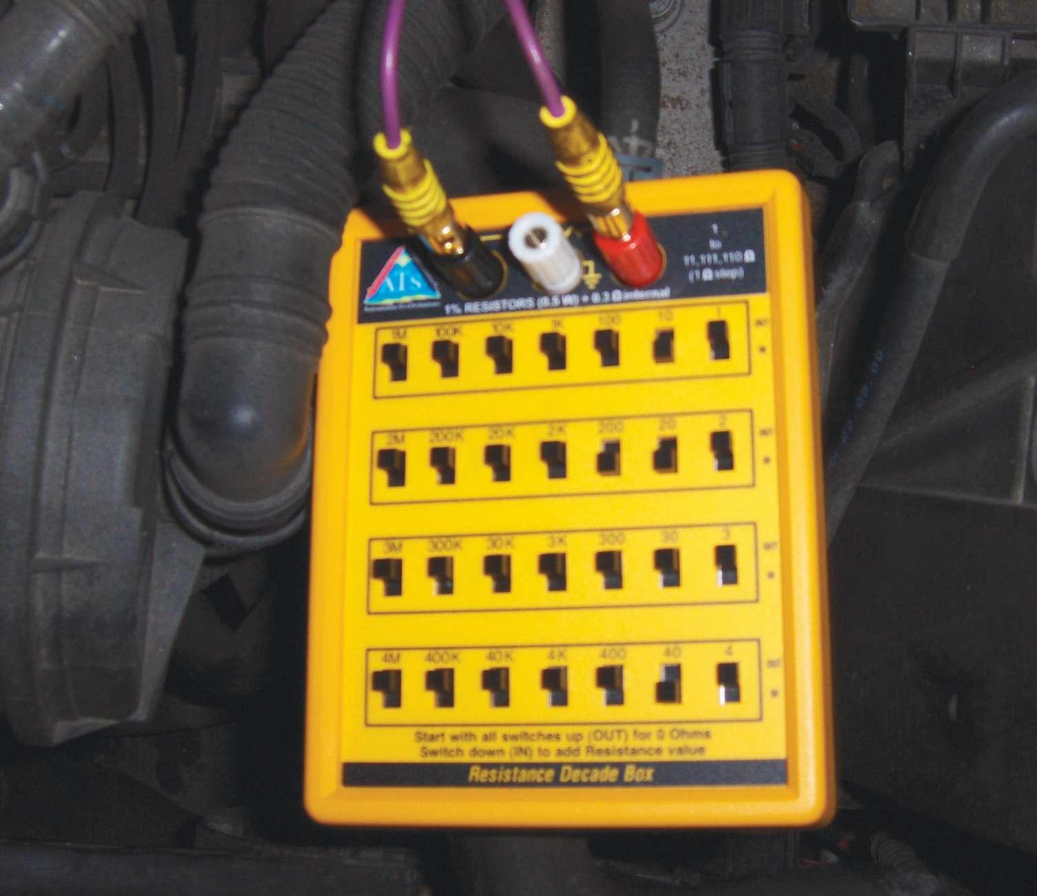
Figure 3. Automotive Test Solutions makes a box that can put differing amounts of resistance in a circuit for testing purposes by simply f ipping a switch.
problem and that it is not caused by a faulty fuel level sender unit.
If it’s not the fuel level sender unit, what could it be? Immediately we conjured up the idea that there is an issue with the PCM or the instrument cluster.
Why? Because what are the chances there are two separate issues causing a problem ref ected on the instrument cluster? Both are high risk propositions. How do we discern which one is the problem?
1. Check TSBs and Identif x. Chrysler had a recall for fuel pumps and Identif x told us what we already knew. Time to start testing. 2. Diagnose and repair any bad sensors or actuators. So, where do we begin with our diagnosis? First, we simply plugged in different scan tools, because not every scan tool gave us both the fuel level PID as both a voltage and fuel level.
The Launch X431 was a surprisingly good Euro-Asian tool, and following it up with the Snap-on Modis and the OTC Pegisys we found that they all agreed that the fuel level was supposedly 21%.
We knew that this was not really the case. We got a little more information from the Modis, because it showed us that the fuel level sender unit voltage was 2.84 V (see Figure 2 on page 25).
After looking up the specif cations, an empty fuel tank should have had 8.6 V while a full one should be 0.6 V. So, if we took the 2.84 V fuel level sender unit voltage as gospel truth, the fuel tank should have been at three-quarters.
Yet, we should have known better than to make such an assumption. The fuel tank

Sensor position 1 2 3 4 5 Operating Mode 2WD 4WD Part time Neutral Neutral 4WD low Sensor Resistance (ohms) 1124-1243 650-719 389-431 199-221 57-64
Figure 4. Using specif cations found on Identif x, we found that the switch was faulty. We found that the four-wheel-drive switch was bad by simply looking up the specif cation and performing an ohms check. The PCM was not to blame at all, nor the instrument panel.
was probably at about 50% because the customer informed us of the mileage he put on the vehicle since his last f ll-up. When we start seeing all these numbers, it is easy to start getting confused.
So, we decided to measure voltage at the fuel level sender unit’s signal wire to verify our scan readings. We knew the part was brand new from a previous attempt at repair, but you never know whether or not a part is defective.
What we found only confused us more. We had 4.8 V leaving the sender unit. This corresponded with our belief that the tank was actually half full even though it was reading otherwise. After all, 4.8 V is about half of 8.9 V.
But, where did the 2.84 V on the Modis come from? And, if the PCM thought it was receiving 2.84 V, why wasn’t the gauge at 75%?
We verif ed that we were getting 12 V to the sender unit and we found the sender unit’s signal wire at the PCM was 4.8 V.
Being in denial that the PCM was to blame, we decided to make sure that the new fuel level sender unit was indeed operational. We did this by using the specif cations for ohms of resistance that the sensor would regularly have under different fuel level conditions and replicating it by placing resistors in place of the actual component.
We looked at the ohms specif cation and found that the sender unit was supposed to have 5 ohms of resistance with a full tank and 270 ohms when empty.
Here were our results on this Jeep Liberty: • 20 ohm resistor: full tank • 30 ohm resistor: 7/8 of a tank • 45 ohm resistor: 3/4 of a tank • 62 ohm resistor: 1/2 of a tank • 77 ohm resistor: just below 1/2 a tank • 94 ohm resistor: 1/4 of a tank • 109 ohm resistor: 1/8 of a tank • 124 ohm resistor: tank at empty
The following, though tedious, proved that at half a tank of gas as dictated by ohms of resistance the gauge will read empty. We saw it with our own eyes that we were able to predictably change the fuel level using this method. So, as long as our specif cations were right, the only thing to blame was the PCM itself.
There was just one piece missing from the puzzle. Will the PCM f x the four-wheeldrive problem where it would show 2WD drive when it was in 4WD on the dashboard and vice versa?
None of the scan tools we had showed a PID for the four-wheel-drive switch position, so we had to pull out the switch to see if the switch was OK before condemning the instrument cluster or any other component.
Using the specif cations on Identif x, we found that the switch was faulty (refer to Figure 4 above).
The PCM was not to blame at all, nor the instrument panel! The switch was broken, as its ohms for 2WD were f ip-f opped with the resistance measured on 4WD-HI.
Why did we go into detail about this? This vehicle had two legitimate problems: One was that the PCM was causing the wrong

Mis-diagnosing a PCM can be expensive, since a replacement PCM can’t be returned.

fuel level and the other the bad switch was causing the cluster to show the wrong driving mode. It is easy to get f ustered when cars do this, but just keep things logical and trust your testing results. 3. Look for illogical PID data. So, our testing proved two things. First, the 4WD issue was not related. Second, the PCM was incorrectly interpreting the signal voltage from the fuel level sending unit.
We could have diagnosed this vehicle a lot quicker by simply just looking for illogical PID data. Here’s what stuck out to us: How can the fuel level sender unit voltage PID suggest the tank is at least half a tank, but the fuel level PID as a percentage thought the tank was nearly empty?
The Modis specif cally had two contradicting values, so the only possible cause would be a bad PCM.
Why? The fuel level PID is simply an interpretation of the fuel level sender unit voltage PID. The fuel level sender unit is not responsible for interpreting its voltage signal. It simply just sends it out to the PCM. So, the only thing that can be blamed for the wrong fuel level PID would have been the PCM.
If it was a bad instrument panel, it would just have the wrong fuel level displayed instead of contradictory parameter IDs. Bad wiring from the fuel level sender unit might send incorrect voltage to the PCM, but it could not make the PCM make a false interpretation of that voltage.
We did not even have to modify the signal voltage using resistors to prove this or even check voltage at the actual sending unit! All we needed was a scan tool. Why? Even if the PCM said one voltage was coming from the sender unit and our meter gave us another, only a PCM issue can make PIDs that contradict one another.
All the bad wiring in the world cannot make a module think voltage is one thing and then interpret that voltage to be something else that would make no sense. A new PCM f xed the fuel level issue.
See how by (1) checking TSBs (at least we found out that we had to do some testing), (2) diagnosing any non-module components (such as the 4WD issue and the sender unit), and (3) looking at illogical PID data we were able to logically condemn the module and feel good about it, too?
Next time we are going to take this approach and apply it to a BMW X5 air suspension system just to prove no matter how complicated the system, we can use the same simple logic to diagnose the vehicle. ●

Tech tip
Causes for repeat failures of fuel pumps
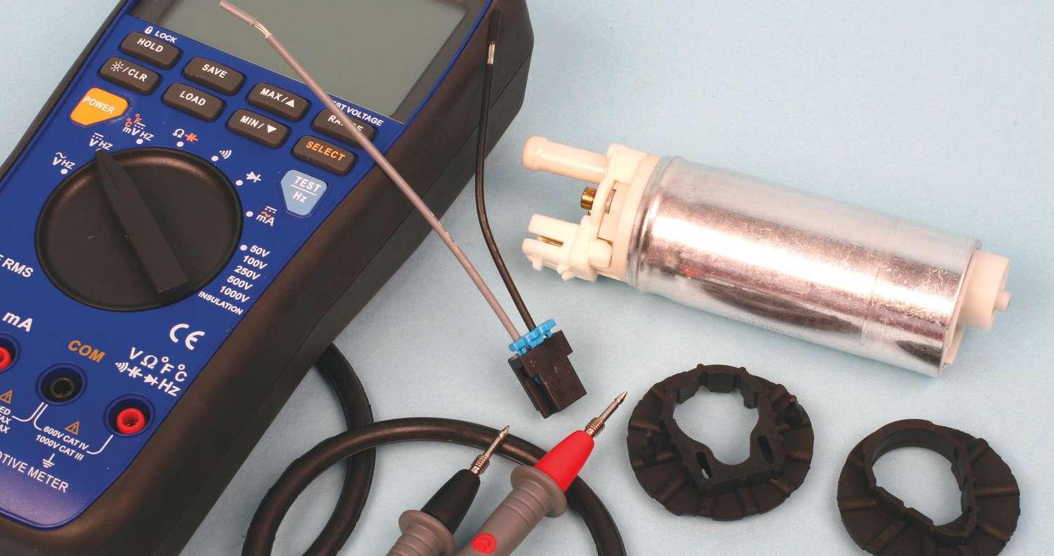
TURN DOWN THE HEAT
Several years ago, Identif x published an article titled “Fuel Pump Blues,” which dealt with repeat fuel pump failures. A poor ground caused excessive heat buildup and was responsible for this repeat problem.
The article concerned a ground problem behind the left rear wheel well on a 1987 Chevrolet Celebrity with a 2.5 liter engine. The current draw on this circuit was 2 to 4 amps with the pump achieving 9 to 13 psi of operating pressure. Today’s fuel pumps are designed to create full operating pressures of 60 psi to 66 psi.
Obviously, the current draw is much higher. Most high-pressure systems, such as the one found in a 2000 Chevrolet Express van with a 5.7 liter engine, will have a current draw of 9 to 11 amps. Consequently, the potential for building excessive heat caused by high resistance has greatly increased.
The f rst area of concern for excessive heat is the actual fuel pump itself. When the fuel tank is continually run with a very low fuel level, the fuel will no longer have the ability to keep the pump cool.
Then there is the problem of poor connections at the fuel tank sending unit resulting in excessive heat, which will eventually damage or melt the connector and reduce the life of the fuel pump. What is the best course of action when multiple fuel pumps are installed and there are no visible problems at the sending unit connector? In this case, the place to look is the fuel pump relay.
This particular vehicle has no oil pressure switch backing up the fuel pump relay. Because of this, all of the current to the fuel pump is going through the fuel pump relay. Should there be a problem with the fuel pump relay or the underhood fuse relay center, the current f ow of the circuit will drop causing the pump to work harder to produce the same amount of pressure. This will result in repeat fuel pump failures.
What are some of the common problems found at the relay and/or the underhood fuse relay center?
1. Poor terminal contact between the fuse block terminals and the relay. This will create excessive heat and eventually damage the underhood fuse relay center by causing the plastic housing to melt. Additionally, today’s terminals are made using less material. This decrease in maternal may cause the terminals of the relay center to deform, resulting in poor terminal contact. 2. Possible problem with the 12-volt supply to the relay from the powertrain control module (PCM). In several cases, the PCM was unable to supply full voltage to the relay causing the contacts of the relay to make poor contact. This created high resistance across the contacts of the relay which in turn created a build-up of heat. 3. Like the problem with the power feed from the PCM, a ground problem for the fuel pump relay also will cause the contacts of the relay to make a poor connection. Again, poor contact will create higher resistance and create excessive heat.
When servicing a fuel pump, be sure to check the connections at the fuel tank sending unit and the underhood fuse relay center. Verify that the ground for the coil side of the relay is in excellent condition and that the computer is able to supply full system voltage to energize the relay. These tips can save the aggravation of repeat fuel pump failure. ●
Information for this Tech Tip is courtesy of Identif x Inc. See www.identif x.com.