10 minute read
Tracing sensor wiring and checking for ‘lazy’ sensors

from Auto Service Professional - July/August 2015
by EndeavorBusinessMedia-VehicleRepairGroup
Advanced O 2 sensor diagnostics
O
ver the years we covered a lot of the basics concerning oxygen and air-fuel sensor diagnostics. This includes their basic operation, the differences between oxygen and air-fuel sensors, air-fuel ratio sensor voltage specifcations, the differences between zirconium and titanium dioxide oxygen sensors, and using emissions analyzers to verify Lambda.
If we can understand all of the preceding, there is not much more that we need to know in order to test these sensors. However, we have not yet covered tracing O 2 sensor wiring and checking for a “lazy” sensor. After reviewing the basics, we will move onto troubleshooting these more advanced oxygen sensor issues.
Understanding fuel control
Oxygen and air-fuel sensors are the vehicle’s personal emissions analyzer.
These sensors measure how rich or lean the exhaust is.
The “front” sensors, located in front of the catalytic converter, are the ones that are used to determine fuel control. On a scan tool, the B1S1 and B2S1 are the front sensors, as the “S” means “side,” and “1” means that it is in front of “2,” which would be the rear sensor. The B stands for “bank,” and 1 and 2 indicates which bank of the motor is being referenced. Being that motors are in all different positions in different vehicles, the technician needs to look up the fring order on an information system in order to know which bank is 1 or 2. The front sensor is always on the same side as cylinder number one in the fring order.
Why are vehicles designed this way? Obviously, if the exhaust goes through the converter, the emissions are cleaned up and this affects the signal. For this reason, the front sensors are located in front and are designed to be sensitive so that they can detect fuctuations in the air-fuel mixture. When the air-fuel or oxygen sensor senses a rich fuel mixture in the exhaust, the PCM takes that information and
Figure 1: Depicted here is a graphic representation of how the PCM reacts when the front oxygen sensors detect an air-fuel mixture above or below Lambda. then tries to do the opposite to make a fuel mixture that is perfect (called “Lambda”) by sending fuel trims in the opposite direction. The same is true when the oxygen sensor senses a lean fuel mixture in the exhaust. When this occurs,
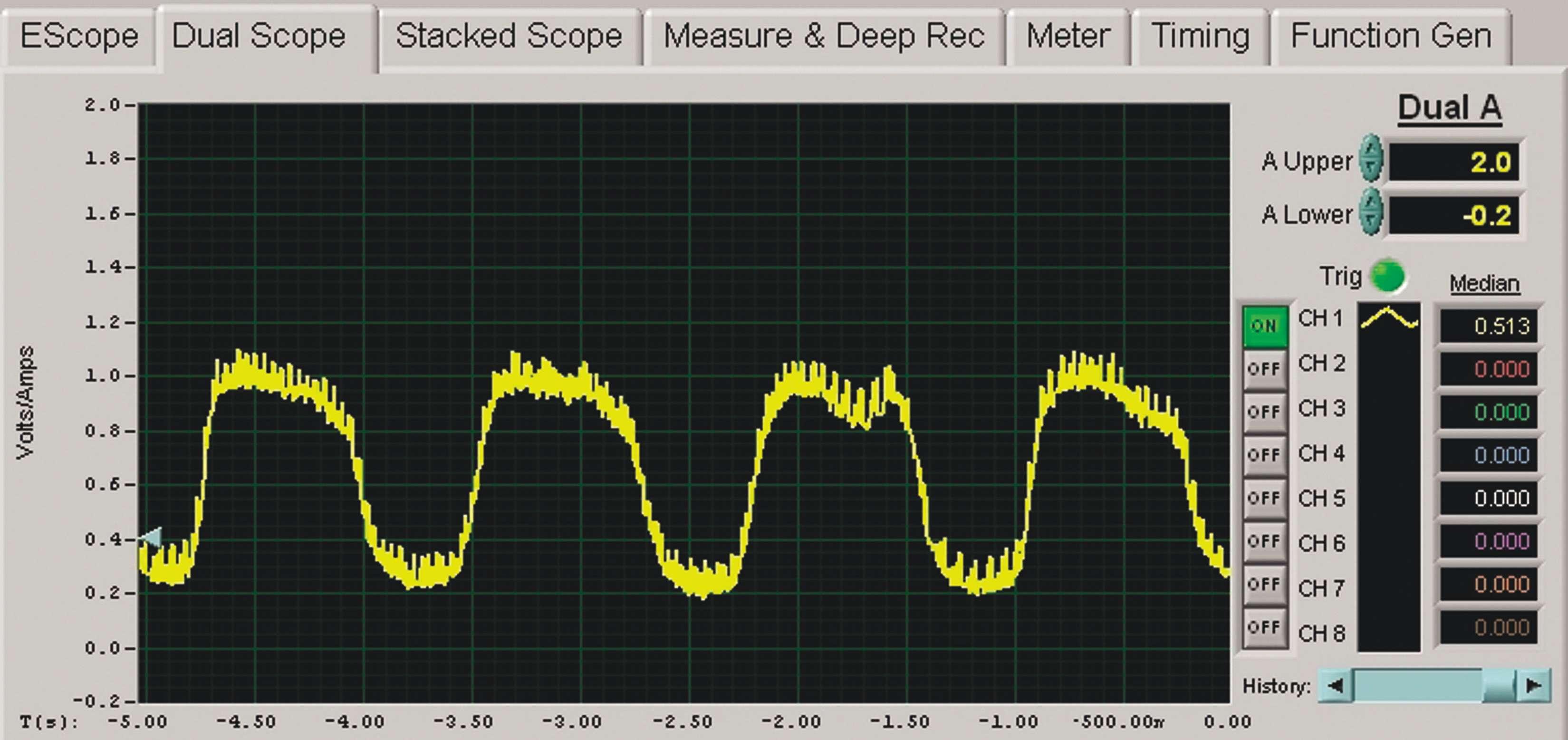
Figure 2: This oxygen sensor, even though it is bad (it is shifted rich), switches within the correct amount of time. The labscope being used here is the EScope from Automotive Test Solutions.
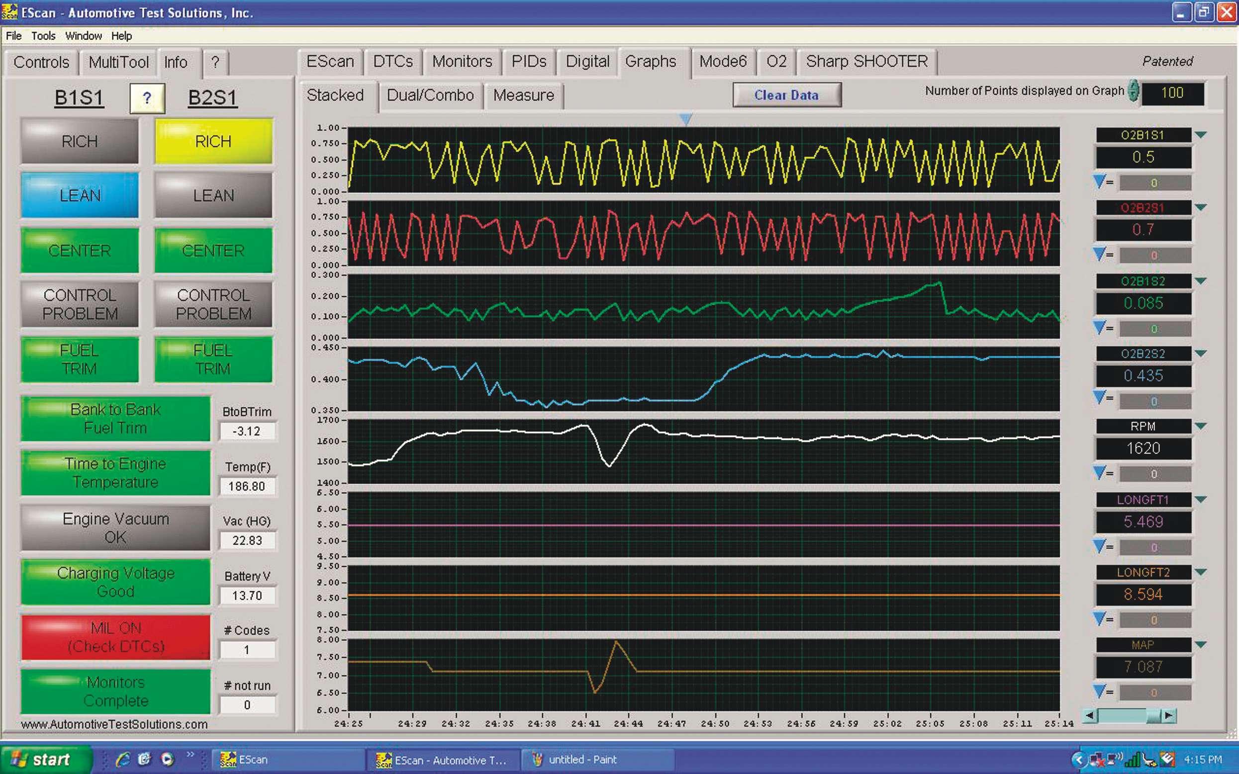
Figure 3: Shown here is an example of reading multiple PIDs. The top two columns on this screen shot show the B1S1 and B2S1 oxygen sensors. As one can see, both go up and down around the same time. One is not faster than the other. By using a scan tool that graphs multiple PIDs at the same time, such as the EScan, picking out a lazy oxygen sensor is a snap.
the PCM takes this information and adds fuel trim to enrich the air-fuel mixture in order to achieve Lambda again. Figure 1 shows us how this works and provides a graphic representation of how the PCM reacts when the front oxygen sensors detect an air-fuel mixture above or below Lambda.
When we look at a zirconium or titanium dioxide oxygen sensor on a scan tool, the technician can see these adjustments in real time. The waveform tends to oscillate above and below 450 mV. When the sensor trends above 450 mV more often than not this indicates a rich condition and below
this voltage indicates a lean condition. A titanium dioxide sensor will read the same on generic OBD II, but on Chrysler products this reading in OEM-enhanced datastream is between 2.6 to 3.4 V, 3.0 V being perfect Lambda.
Air fuel sensors work the opposite. They refect a lean condition when their voltage increases and a rich condition when their voltage decreases. This is identical to how Lambda works on an emissions analyzer. Above 1.0 is lean while below is rich.
Diagnosing ‘lazy’ oxygen sensors
Oftentimes, when the technician has a performance-related DTC, the oxygen sensor looks like it is operating normally. Back before scan tools offered graphing capabilities, it was time to whip out the labscope.
Good oxygen sensors tend to have even waves in the 150 mV to 850 mV range while ascending or descending within a 100 mS or less when the system is in closed loop. An oxygen sensor usually switches between a high to a low voltage and back to a high one again in less than a second. Of course, this is only a rule of thumb and not true of every vehicle. Some may switch much quicker, while others would switch slower. Refer to Figure 2: This oxygen sensor, even though it is bad (it is shifted rich), switches within the correct amount of time. The labscope being used here is the EScope from Automotive Test Solutions.
Is there an easy way to fnd out on a scan tool? Perhaps. Many scan tools do not have the update rate that a labscope has, so even if its graphing function shows a time division, it might not be an accurate reading.
Nonetheless, on vehicles with motors that have two banks, there is a way to test the oxygen sensor without checking a known good sensor on an identical vehicle. Simply graph both S1 and S2 oxygen sensors at the

Figure 4: This Mercury Mountaineer tests at below the minimum testing value according to Mode 6, which means that it fails. Many scan tools convert Mode 6 into understandable language, but not all of them read Mode 6 continuously. On some scan tools, as long as codes are cleared, one can back out of and back into Mode 6 to get an updated reading.

Circle 105 on Reader Service Card
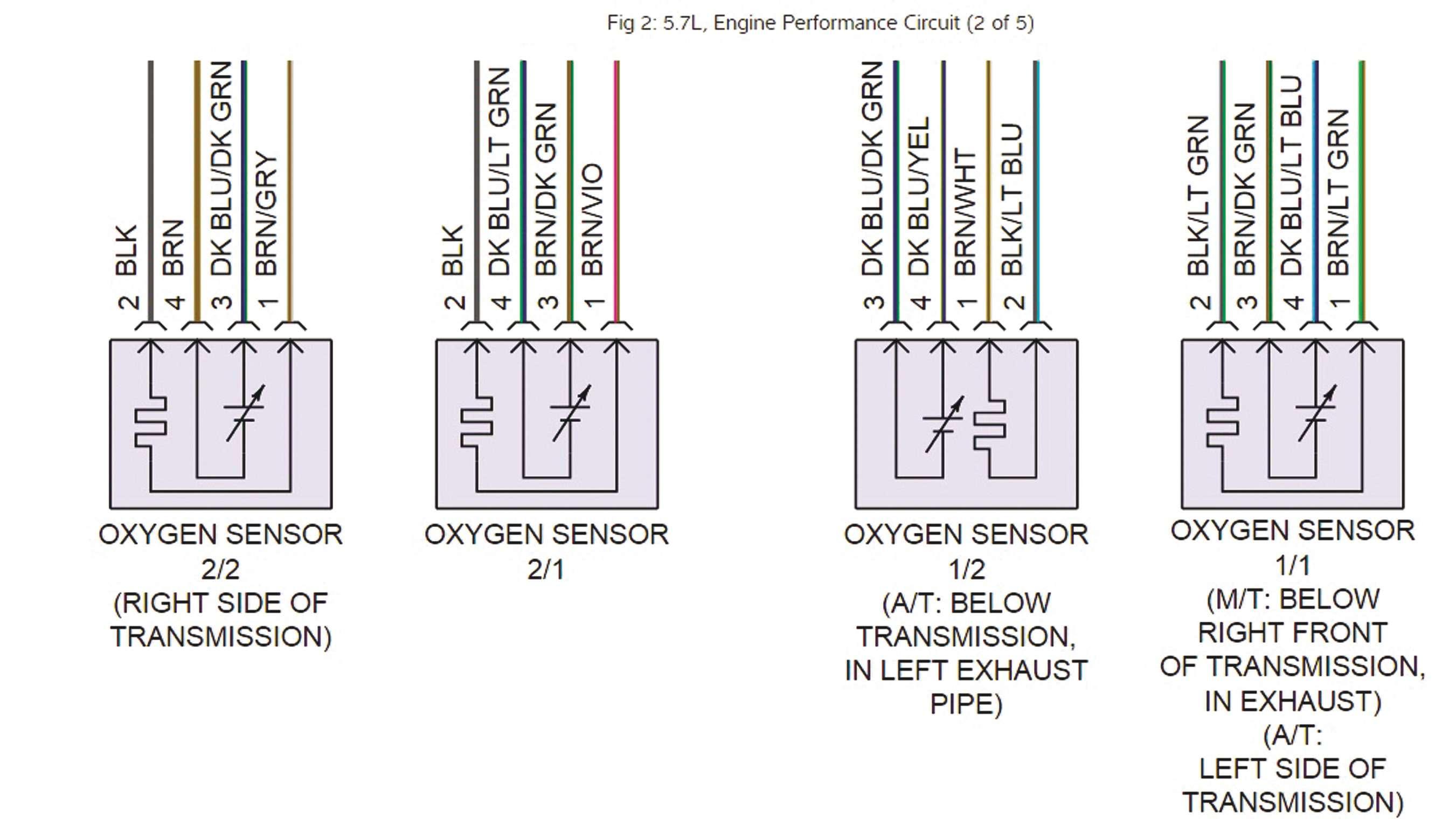

Figures 5 and 6: By looking at a wiring diagram, here provided by Mitchell 1 ProDemand, we can by simply matching colors fgure out which wires belong to the oxygen sensor heater circuit.
same time. Their voltage oscillation should be identical. If one goes up and down quicker than the other, and the slower one is the one that happens to have the DTC, the slower one is “lazy.” Now it’s time to get a new one that will work quicker!
See Figure 3: The top two columns on this screen shot show the B1S1 and B2S1 oxygen sensors. As one can see, both go up and down around the same time. One is not faster than the other. By using a scan tool that graphs multiple PIDs at the same time, such as the EScan as pictured here, picking out a lazy oxygen sensor is a snap.
When in doubt, look at Mode 6. If the oxygen sensor PID is showing movement and the DTC is not for a heater circuit, then the technician knows that the PCM is receiving the data. By default, if the technician looks at Mode 6 when there is a DTC, the sensor is probably going to have failed the test.
However, if the technician checks the PID and everything looks OK, he can still enhance his learning by looking at Continuous Mode 6. If the sensor fails the Mode 6 test, the technician can be assured that the sensor is probably not OK. There is something about it that the software engineers for the manufacturer do not like and so the PCM interprets the signal as a failure for whatever reason. Be sure to check TSBs to make sure that there are not any PCM refashes (or even replacements) due before changing the sensor in this situation.
See Figure 4: This Mercury Mountaineer tests at below the minimum testing value according to Mode 6, which means that it fails. Many scan tools convert Mode 6 into understandable language, but not all of them read Mode 6 continuously. On some scan tools, as long as codes are cleared, one can back out of and back into Mode 6 to get an updated reading.
Heater circuit diagnostics
One of the most common oxygen sensor DTCs a technician fnds is related to oxygen sensor heater circuits. Many shops just throw a sensor at the problem, and more times than not they are right. However, if the technician wants to diagnose the

Brown/Violet and Brown/Light Green wires belong to the heater circuits of the front oxygen sensors.
In Chrysler vehicles, four wire oxygen sensor heater circuits tend to be powered by the PCM instead of grounded (they are grounded to the chassis). On Mitchell 1, the heater circuit appears as a line then bends back and forth like a tributary in the picture of the sensor. Knowing this, the technician can quickly look right at the oxygen sensor and know which wires are for the heater circuit without having to look at another diagram such as that shown in Figure 6.
Now that one knows the right wire, it
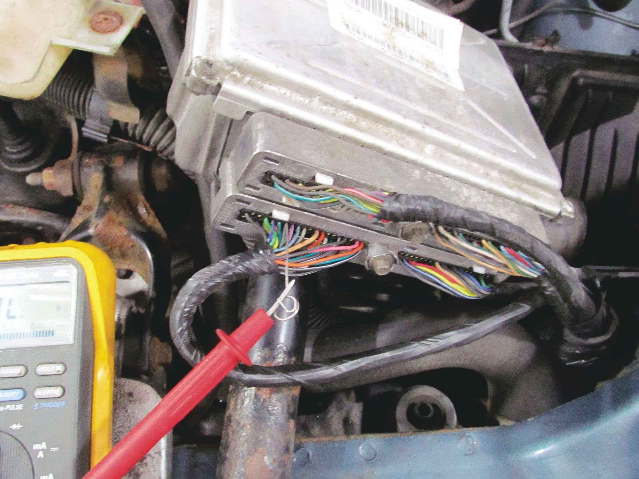
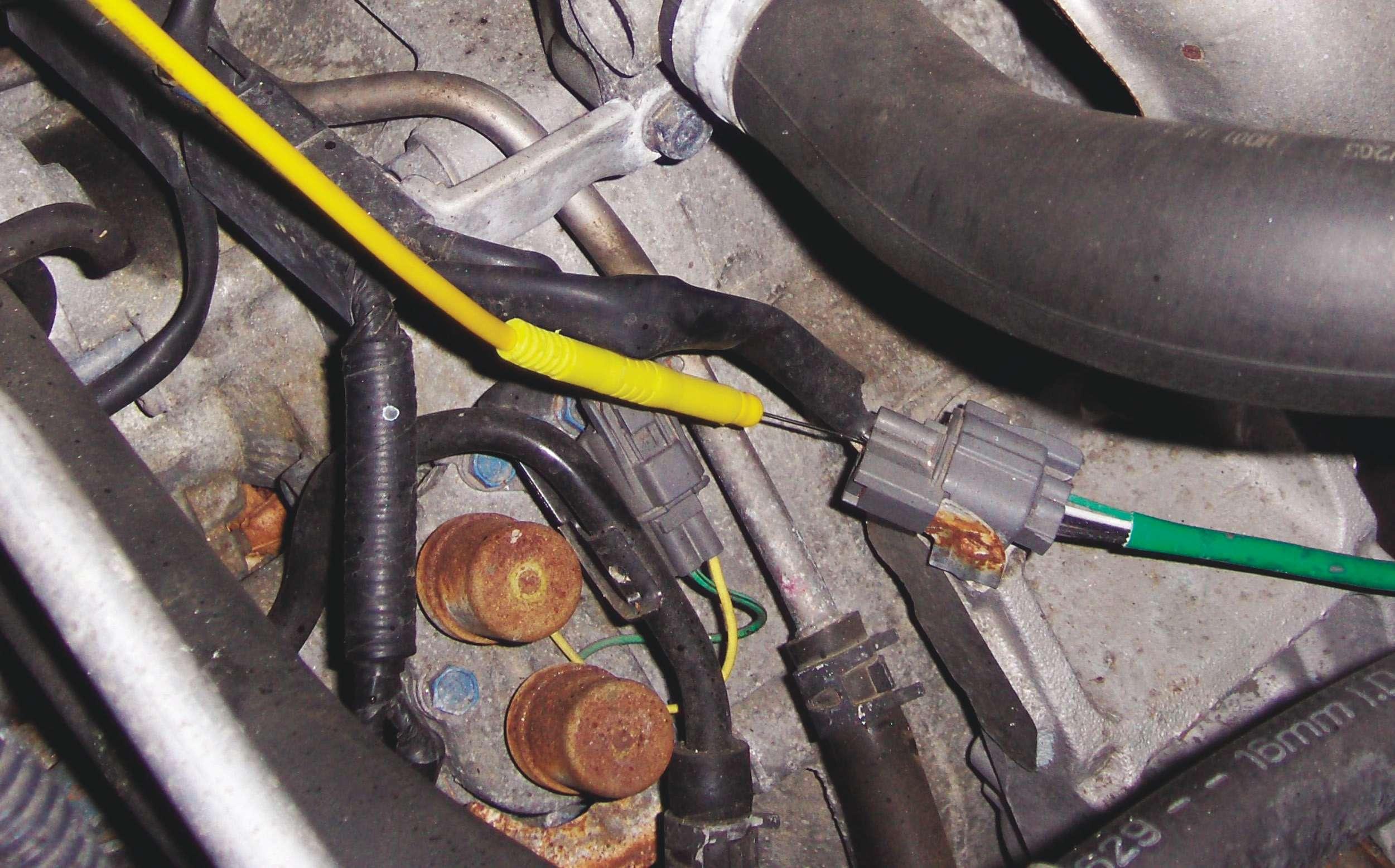
can be measured at the heater circuit wire. If the technician is actually getting power, he can then place an amp clamp on the wire and see if there is any amperage indicative of the heater circuit working. If not, the heater in the sensor itself is not working. If the technician does not fnd power going to the sensor, and if a broken wire cannot be found easily, it is best to go straight to the PCM and fnd Figure 7: Here, on a different vehicle, the tech is checking the wire related to the oxygen to see if 5 V can be measured at the heater circuit wire. sensor heater. Back-probing a problem correctly (something that may be as fnding the right colored wire from the necessary if the vehicle is a comeback), it wiring diagram and sticking a T-pin into is not diffcult to do if one follows proper where the wire connects into the back so procedure. no insulation has to be broken. Break
First, the technician needs to know what ing insulation can lead to corrosion in the he is looking at and to do this he will need wiring in the long term. If there is not any an information system. Let’s take a 2008 power leaving the PCM for the heater upon Dodge Ram 5.7L, for example. By looking startup, the issue is internal to the PCM at the wiring diagrams (see Figures 5 and 6 itself and it will need to be replaced. for wiring diagrams provided by Mitchell 1 However, if there is power, there is a ProDemand), we can fgure out which wires break in the wiring somewhere farther down belong to the oxygen sensor heater circuit the circuit. The technician will need to by simply matching wire colors. Note that trace the break or lay a new wire. ●
PCM (see Figure 8) is as easy is simple enough to check power right Figure 8: Backprobing a PCM is as easy as to the sensor to make sure the PCM is fnding the right colored wire from the wiring actually issuing the command. Refer to diagram and sticking a T-Pin into where the wire connects into the back so no insulation has to be Figure 7: Here, on a different vehicle, broken. Breaking insulation can lead to corrosion the technician is checking to see if 5 V in the wiring in the long term.
