18 minute read
PISTON RINGS

from Auto Service Professional - June 2021
by EndeavorBusinessMedia-VehicleRepairGroup

Understanding the role of these critical components
BY MIKE MAVRIGIAN
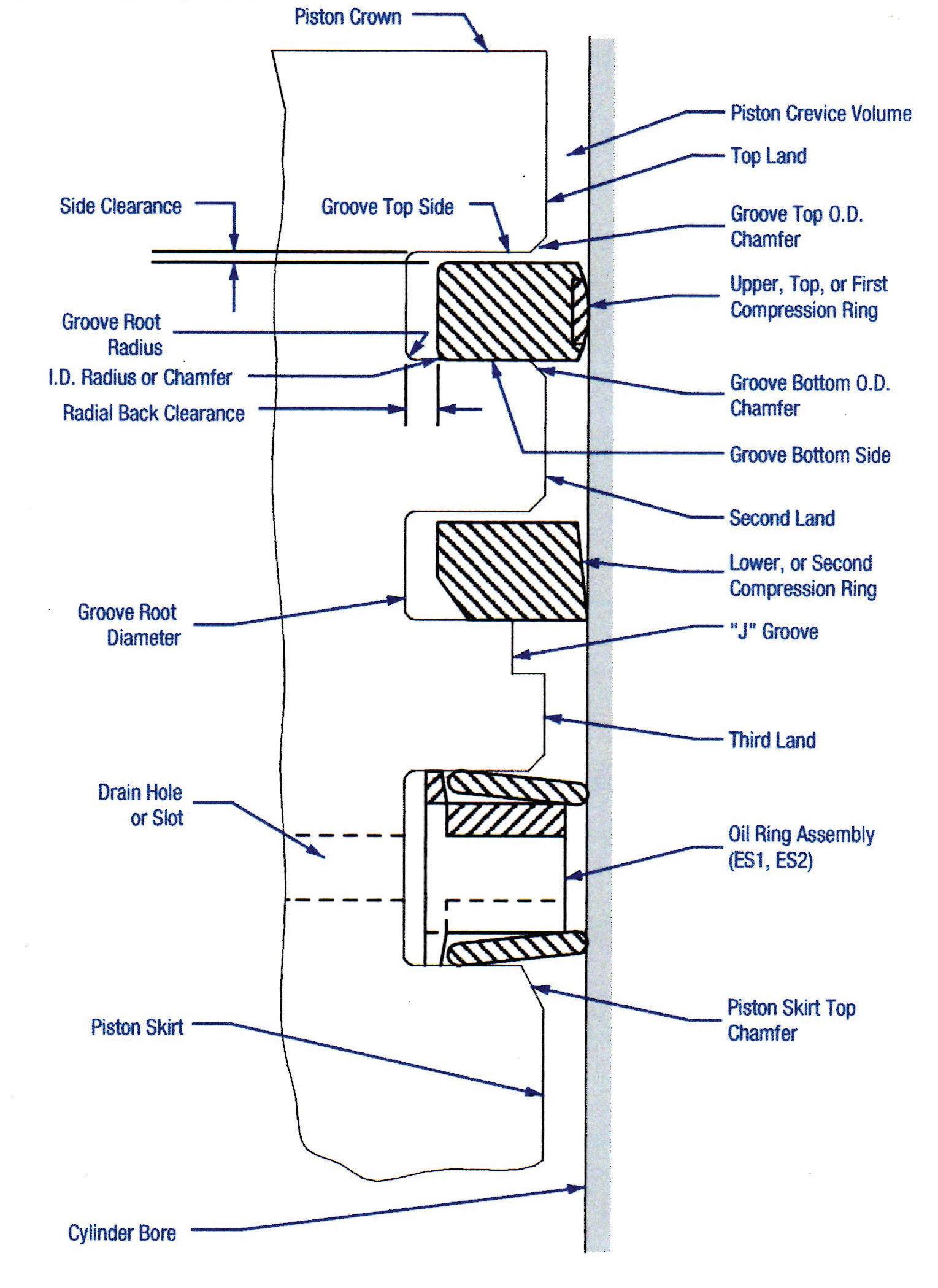
Fig. 1: Cross-sectional view of ring-to-piston identity and dimensional reference. Note how the oil ring expander causes the upper and lower oil ring rails to cock at slight angles to aid in sealing during up/ down strokes.
VEN IF YOUR SHOP DOES not rebuild
Eengines on a routine basis, it’s beneficial to gain an understanding of the role that various engine components serve. In this article, we’ll discuss piston rings, their purpose and tips on ring service.
Piston rings, in simple terms, are the components that form the dynamic seal between the piston and cylinder wall. Consider, for example, that the rings must provide both a sealing function and an oil control function, in a range of conditions and temperature extremes — from winter-morning cold starts to prolonged highRPM, high-load operation in hot weather. Also consider that most pistons “move” and “grow” laterally within the cylinder during operation, creating a sometimes unpredictable sealing area and contact surface.
It should be obvious that long-term wear of cylinder walls and rings can create ring sealing and blowby issues, even a new OEM engine can experience issues if the rings were not manufactured properly. As a case in point, KIA recently issued a problem with oil rings in some 2020-2021 Soul and 2021 Seltos 2.0L engines. Apparently, the oil ring rails were not heat treated properly, resulting in excessively hardened rails, causing excessive wear on the cylinder walls. This has the potential for excessive oil consumption, exhaust system/ converter damage, and minimizing available oil for the rod bearings.
Virtually all current automotive applications feature three rings per piston. The top ring is exclusively a compression ring, meaning its function is to seal the expanding combustion gases above the piston. Without an effective combustion seal, of course, these gases would leak around the sides of the piston, resulting in a power-robbing process known as blow-by.
The top ring is sealed against the cylinder wall and the lands of the ring groove by the pressure differential created during the piston’s combustion cycle. As pressure increases above the ring and between the ring’s inside diameter and the piston groove, the ring is forced downward and outward, creating a tight seal over a wide range of engine RPM. The primary job of the top ring is to serve as a compression seal. It also helps to protect the second ring from combustion heat.
Most modern OE compression rings feature a premium grade cast iron, ductile iron or steel alloy coated either with a heat-resistant graphite, plasma-molyb-

Fig. 2
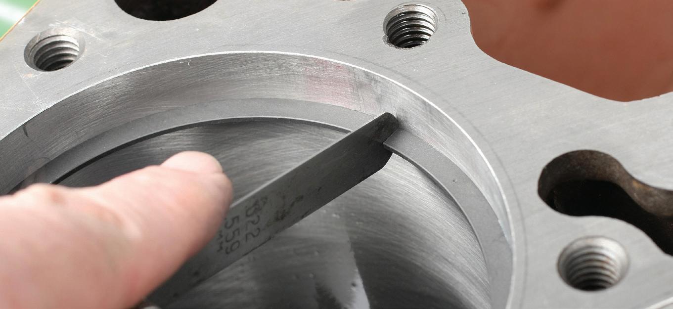
Fig. 3
Fig. 2: When measuring the gap for top or second ring gap, the ring must be placed squarely in the cylinder bore. A quick and easy way is to use a ring squaring tool which is adjustable for bore diameter. Place the ring into the bore, about a quarter-inch or so down from the deck, and insert the squaring tool. The ring is immediately leveled in the bore. If the ring is not level, your gap measurement will be inaccurate.
Fig. 3: Using a feeler gauge, measure the existing ring gap. Compare this to the OEM or piston maker’s specification (gaps will often differ between top and second rings). denum or chromium facing material. Graphite and “plasma-moly” are relatively soft and porous ring facings with excellent oil carrying capacity and comparatively fast conformability (or break-in) to the cylinder bore surface. Chrome, used today primarily by overseas OEMS, is a much harder, non-porous material.
The second ring, although commonly referred to as a compression ring, primarily functions as a final oil control (about 80% of the second ring’s duty is oil control and about 20% for compression control). The two common designs are RBT (reverse-twist, taper face and a THG hook groove, sometimes called a Napier ring). The reverse twist, taper faced second ring is very common in performance ring sets. An inside bottom bevel causes torsional twist in the ring. The twist prevents oil migration from creeping up behind the second

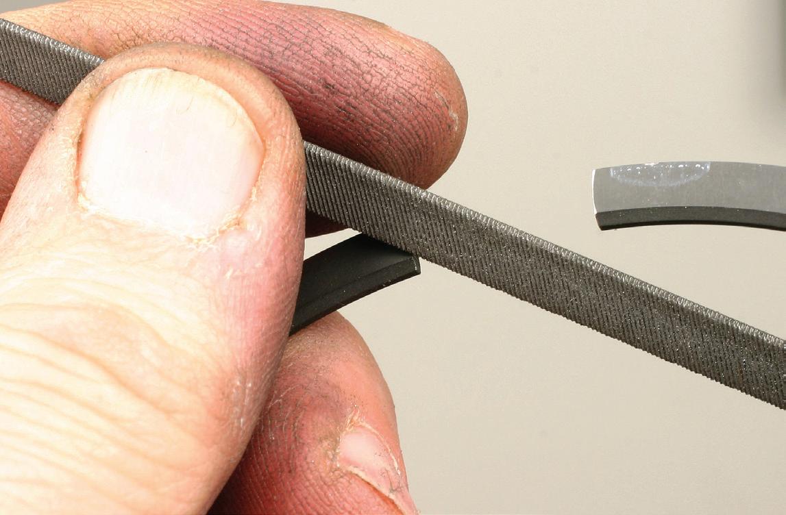
Fig. 4: When dealing with an OEM engine, the need to file-fit top and second rings will be rare, but depending on the application, this might be required. For file-fit rings (where the existing gap is too tight), the ends of the ring must be filed squarely. A ring filer makes the job easier and more precise. Don’t get carried away. File a bit, clean the ring, re-check the gap in the bore and continue the process in small increments until you achieve the desired gap. Remember to check the gap (and correct where needed) at each cylinder, and keep each ring dedicated to the cylinder in which it was checked and fitted. Small variances in cylinder bores might exist, so for tailor-fit ring gaps, dedicate each ring to one cylinder (fit the top ring for cyl 1, then top ring for cyl 2, etc. for all cylinders; then fit the second ring for cyl 1, then cyl 2, etc.). Keep rings organized per cylinder location. There is never any need to file fit oil ring rails. ring. The taper face scrapes oil from the cylinder wall for oil control. Most RBT second rings are made from grey cast iron. THG second rings also feature a twist, but with no inside bevel and no taper. Instead, THG features a hook groove on the bottom O.D. THG rings offer slightly better oil control than RBT. THG also acts as a check valve to relieve excessive combustion pressure built up under the top ring, helping to stabilize the top ring (avoiding or minimizing ring flutter).
Like the top rings, OE second rings are typically coated with a phosphate or plasma-molyfacing to protect the rings from combustion-related heat. These rings usually also feature a low-tension, tapered face designed to reduce drag while maintaining the ring’s oil control capabilities. Most major OE and aftermarket suppliers build a reverse torsional twist into the second ring to create a more effective seal at the piston land, preventing oil migration behind the ring.
The third ring assembly serves as an oil control ring package that essentially removes oil from the cylinder wall during the power stroke. Oil control rings feature multiple components, including an expander, or spacer, and upper and lower scrapers (rails).
The oil rails in this classic design rest on angled expander pads, which deliver both lateral and vertical force to seal the top and bottom surfaces of the ring groove.
Oil rings are offered in standard-tension (for most street applications, and high-output engines susceptible to bore distortion) and low-tension designs. Standard-tension rings apply around 21 pounds of tangential pressure against the cylinder wall. Lowtension designs apply about 15 pounds of tension. The oil ring rails “scrape” excess oil from the cylinder walls and serve to provide oil control. If the oil ring rails are worn or are too hard and apply too much pressure against the walls, oil blowby can occur, allowing oil to escape into the combustion chambers, fouling spark plugs and potentially contaminating the exhaust stream and result in catalytic converter damage.
RINGS AFFECT ENGINE PERFORMANCE
The greatest level of friction that occurs in an internal combustion engine is created by the piston rings rubbing against the cylinder walls. This friction has a direct contributor to engine operating temperature.
If burnt oil/smoke occurs exiting the exhaust, this might be the result of oil passing through worn valve
guides/valve seals or passing by the rings. A compression and cylinder leak-down check can confi rm ring function. If a piston dome appears to be washed on edges or across the dome, oil is likely leaking past worn or stuck rings, which might throw misfi re codes P0301P0312, in addition to experiencing a reduction of engine power due to a reduction of cylinder pressure.
If oil ash is accumulated on one side of the spark plug, it is likely that oil is passing through valve guides or seals.
RING END GAP
The best way to start a debate among engine builders is to ask whether an end gap is necessary in the second compression ring.
The fact is, however, that virtually every North American engine manufacturer has determined that an increase in end gap in the second ring actually improves sealing performance. This is due to what’s known as the “Pressure Balance Theory.” Without a second-ring end gap, gases become trapped between the second and top rings. As the piston moves through its power stroke, the buildup of these gases actually lifts the top ring off its land. This, of course, causes extreme blowby and power loss.
Usually measured at a depth of 1.00 inches from the top of the cylinder wall, the ring gap is the installed space between the ends of the rings. When measuring end gap, the ring must be placed in the cylinder, at an equal depth along the entire perimeter. This is called “squaring the ring.” If the ring is not placed at an equal distance from the block deck, this will result in incorrectly measuring the end gap. With the ring properly installed in the bore, use a clean fl at feeler gauge. The gauge must fi t snugly in the gap without the need to apply much force.
Always follow the piston maker’s recommendations for top and second ring gap, as this will vary depending on piston material, bore diameter and application (naturally aspirated, forced induction, nitrous injec-

Say ‘yes’ to OEM TPMS expertise.
REDI-Sensor is built by one of the world’s leading suppliers of OEM TPMS systems – Continental.
It’s ready right out of the box.
Get the full story:
REDI-Sensor.com


Fig. 6
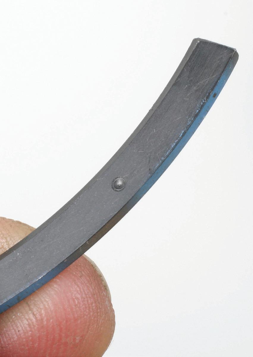
Fig. 7
Fig. 6: With the oil ring expander in place, install the lower oil ring rail, making sure that the ends of the expander butt together and don’t overlap. With the lower rail installed, this will capture the expander. Next, install the top rail. The second compression ring is installed next, followed by the top compression ring.
Fig. 7:
Depending on the application, top and second rings will feature orientation marks, This might include a dot or (for the top ring) the word “top.” Typically a ring that features a dot must be installed with the dot facing upwards. tion, etc.). While you must always refer to factory specifications, for street applications, a rule of thumb is to allow about 0.0045-inch end gap per inch diameter of the cylinder bore. For instance, a 4.000-inch bore might require a ring gap of 0.018-inch. In cases where the bores are a bit worn or if the block has been oversize bored and honed, rings for popular applications are available in sizes to accommodate this (3mm oversize, 0.010-inch oversize, 0.030-inch oversize, etc.). Never assume that replacement rings will provide the proper end gap out of the box. Always perform a gap check to verify this.
In some cases, only “file to fit” rings might be available, wherein the top and second rings are made with a negative or zero gap, which then requires the installer to file the ends in order to obtain the proper end gap. This must be done carefully, using a dedicated ring bench-mount ring filer tool. Material removal must be kept “square” meaning that you must avoid creating unwanted angles. The width of the installed gap must be the same from inboard to outboard of the gap. File carefully, counting the number of strokes during filing, and re-check. In order to avoid removing too much material, file a few strokes, re-check the end gap in the bore, re-file, check, etc. until the correct gap is achieved. If you file too much, the ring is not usable. Once the desired gap is obtained, the filed ends must be carefully deburred using a small, flat, fine file.
If file fitting is required, this only applies to the top and second rings. Oil expanders and oil rails are produced for specific bore sizes (standard or specific oversizes) and do not require file fitting.
PISTON RING TRENDS
The trend in ring design today focuses on reduced friction and high ring conformability. As ring-to-cylinderwall friction is reduced, horsepower is freed and fuel economy is increased simply due to a reduction in parasitic drag. Ring “conformability” refers to the rings’ ability to seal within a bore that is not perfectly round (as often occurs when a bore is distorted during heat cycles and the stress of head bolt clamping). Ring sealing naturally affects power output, emissions control and oil consumption.
This brings up yet another valid reason to use cylinder head torque plates when boring & honing a block.
If a torque plate is not used during bore machining, you will create a round bore under static conditions, yet the bore may distort and go “out of round” once the cylinder head is bolted to the block. Of course, the extent of this distortion is dependent on the particular block in question (some will distort more than others). The point is to make the bore as round as possible when in use. If the bores remain true while the pistons run through their cycles, the more easily the rings can perform their sealing jobs.
Today’s rings are becoming thinner and narrower, in part to promote conformability. Effi ciency, fuel economy and reduced emissions will remain the target goals of engine designers for years to come, and it’s certain that ring size, weight and the ability to seal will continue to evolve accordingly.
As engines continue to be designed as smaller and lighter packages, block decks are becoming shorter and pistons are downsizing. The result: Rings are becoming thinner, in the area of 1.2mm, with 3mm oil rings common.
Ring locations have gradually moved upward toward the piston dome. This trend is likely to continue for several reasons, including both performance and emissions concerns (for example, a smaller “crevice” volume … the circumferential void area between the piston and bore, above the top ring ... is benefi cial in reducing unburned hydrocarbons).
Also, regarding fuel economy, rings are becoming narrower, radially, in an eff ort to reduce ring-to-wall friction. The reduced dimension also allows the rings to be more comfortable (fl exible) to the shape of the bore. This allows the use of lighter ring tension, providing the bore geometry is correct.
Ring makers typically like to see bores fi nished with 280-grit stone. Coated rings are pre-lapped now, so you don’t need to create a rougher surface in the bore. This applies even to chrome plated rings. Today, there’s no need to provide a rougher bore fi nish in order to achieve break-in.
GASKET SCRAPERS

• DROP FORGED FROM HIGH CARBON STEEL • BIT EXTENDS ENTIRE LENGTH OF
HANDLE TO THE STRIKE CAP • BLADE FACE AND SCRAPING
ENDS ARE PRECISION GROUND • BLACK OXIDE FINISH FOR
CORROSION RESISTANCE • LIFETIME WARRANTY
BIT EXTENDS ENTIRE LENGTH OF
ENDS ARE PRECISION GROUND

MADE IN U.S.A.
#855-4ST
4-PIECE SET #855-3ST
3-PIECE SET
Also available individually.
WWW.LANGTOOLS.COM
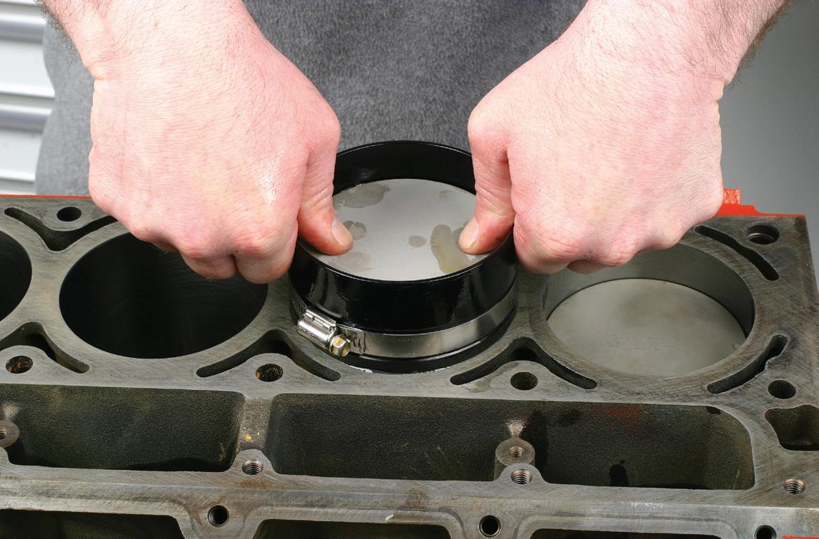
Fig. 8: Currently available ring compressors that feature a tapered inside diameter are far better choices as compared to the old “barrel band“ style tools. The tapered inside walls compress the rings prior to entering the bore, making the task much easier and serve to greatly reduce the chance of ring damage. The tapered compressors are available in billet size-specific models (as shown here) or as split designs, allowing a range of bore size adjustment.
RING INSTALLATION TIPS
Before installing rings onto the pistons, make sure that the piston grooves are absolutely clean and free of any burrs.
Installing rings on pistons is not difficult but care must be taken to avoid deforming or breaking a ring. This is especially important when dealing with second and top rings. Install the oil ring expander first, making sure that the ends remain butted at all times. Install the lower oil rail to capture the lower indent of the expander, then install the upper rail. Oil rails might be installed by spiraling them on by hand.
Unless you’re dealing with very light tension rings, always use ring pliers to install rings on to the pistons. Winding a second or top ring onto a piston can easily create a helix in the ring, resulting in ring distortion that might not recover. When using ring pliers, expand the rings only far enough to install.
Pay strict attention to all ring end gap locations. The goal is to prevent end gaps from being aligned to each other, which will create leak paths. Ring gap orientation may be specified depending on piston or OEM recommendations.
As but one example, following is a recommendation for ring gap orientation. Again, OEM specifications may differ.
Viewing the piston from overhead, with the front of the piston (facing the front of the engine) at 12 o’clock, end gap orientation is as follows: • Oil expander (butted ends) … between 2 and 4 o’clock • Bottom oil rail gap … 10 o’clock • Top oil rail gap … 7 o’clock • Second ring gap … 9 o’clock • Top ring gap … 3 o’clock
During engine operation, rings will likely rotate slightly, but the idea is to keep gaps far enough apart so that they cannot align.
In order to install the connecting rod/piston assembly into the block, the rings must be compressed in order to enter the bores. While adjustable “barrel” style ring compressors do work, billet tapered ring installers are by far the best to use. These feature a tapered inside diameter with a larger top entry and bore-size-compatible bottom diameter (squeezing the rings as the piston moved through the compressor).The downside is that
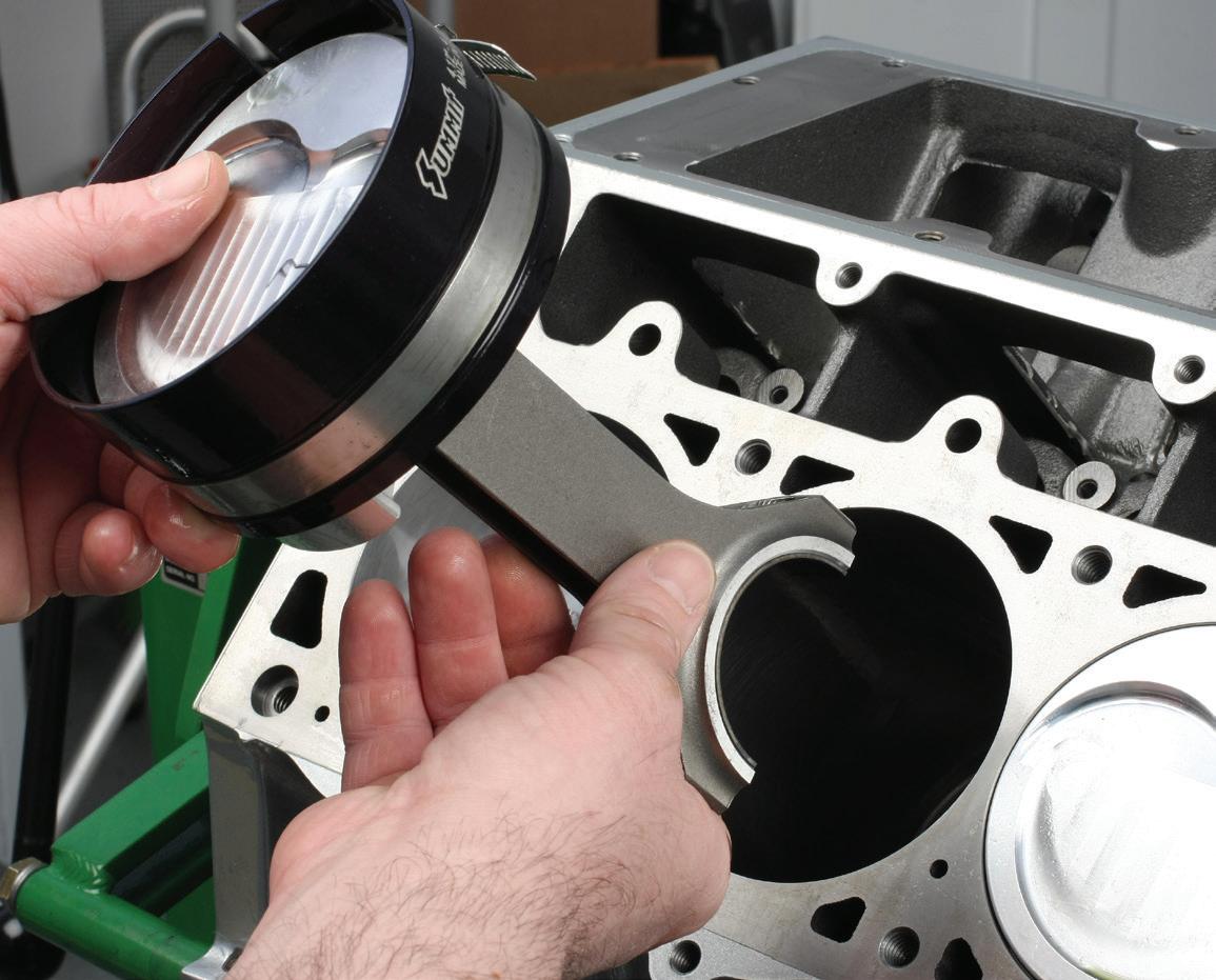
Fig. 9: Make sure that the bore is clean. Apply oil to the bore, the ring package, piston skirts and inside the ring compressor. Verify orientation of all ring end gaps to avoid gap alignment. With the upper rod bearing installed to the rod, slip the rod/piston through the compressor until the ring package is captured, making sure that the piston skirts are exposed. Shown here is a tapered adjustable ring compressor. The compressor’s split gap and worm drive clamp allows bore diameter adjustment for a small range of bore size.
Fig. 10: Insert the piston skirts into the bore and allow the bottom of the compressor tool to firmly contact the block deck. Using finger pressure, push the piston/ring package into the bore until the ring package is fully inserted in the bore. most tapered compressors are made with a specific bore diameter in mind, requiring separate compressors for different sized bores. However, tapered compressors are also available that offer a range of bore diameter adjustment, reducing the number of compressors required in the shop.
Rotate the crankshaft to place the target rod journal near its bottom-dead-center location. Apply engine oil or bearing lube onto the upper rod bearing.
After applying engine oil to the installed rings, piston skirts, the inside of the compressor and the cylinder walls, insert the connecting rod and piston skirts into the compressor. Carefully manipulate the rings until they are all captive within the compressor, with the piston skirts exposed below the bottom of the compressor. Lower the rod into the bore and allow the piston skirts to enter the bore, as well. Making sure that the bearing-equipped rod is aligned with the crankshaft rod journal. While holding the bottom of the compressor firmly against the block deck, push the piston into the bore using hand pressure, applying alternating pressure at the front and rear of the piston dome. If you feel a dead stop, try gently tapping the piston using a clean plastic piston hammer. If more force is required, chances are a ring has contacted the block deck. Never apply excess force by hitting the piston. If in doubt, raise the piston and compressor and start over. Once the top ring enters the bore, remove the compressor tool. While guiding the connecting rod onto its journal, use aplastic piston hammer to gently tap the piston until the upper rod bearing makes full contact with the journal, at which time you can install the lower bearing equipped rod cap. Tighten the rod bolts to specification.
As far as the use of synthetic oils and other ultraslippery materials are concerned, Don’t use a full-synthetic assembly lube or oil at the ring-to-cylinder wall in a fresh engine that features newly-honed cylinder walls. If the lube is super-slippery, the rings might take much longer to seat, or they may not seat at all. Unless otherwise specified by the OEM, for initial breakin, it’s best to use a petroleum-based engine oil. Once the rings are properly seated (depending on cylinder wall surface finish, this might take anywhere from 30 minutes to several days), change the oil and filter and replenish with the oil of choice.