5 minute read
TECH TIPS

from Auto Service Professional - June 2021
by EndeavorBusinessMedia-VehicleRepairGroup

From crankshaft to a tow
CRANKSHAFT THRUST
Engine crankshafts ride on a series of main bearings, one of which features a thrust main bearing that includes a front and rear flange that limits the amount of fore/aft movement of the crankshaft. Typically, crankshaft thrust will be specified in the 0.002- to 0.006inch range (always check the OEM specifications for the specific engine).
Typically, damaged/worn thrust bearings are caused by excessive torque converter pressure, riding the clutch (if the vehicle is equipped with a manual transmission) or a damaged/ misadjusted throw-out/release bearing.
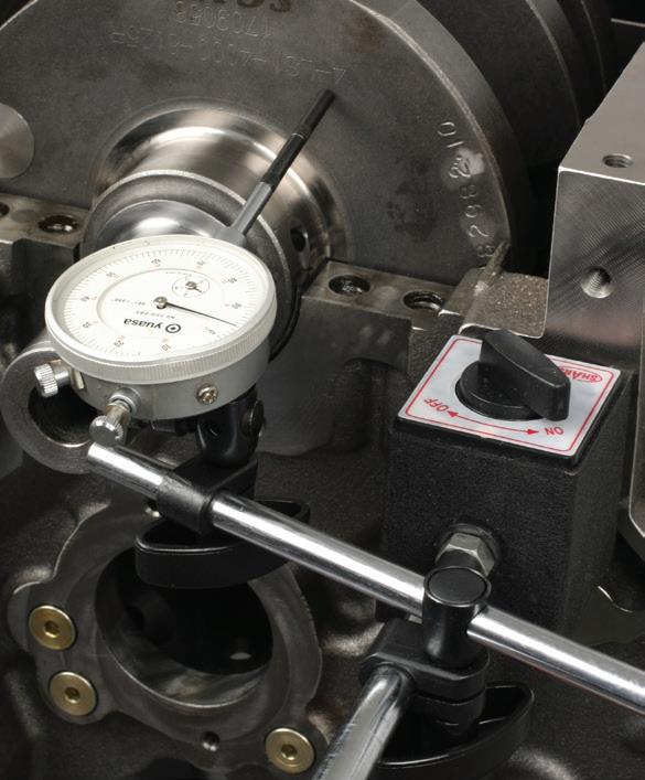
To check crank thrust, mount a dial indicator to the front of the block (using either a magnetic or bolt-on indicator base). Position the dial indicator probe at the front face of the crankshaft snout (or the face of the front counterweight), making sure that the probe is parallel with the crankshaft (avoid angle contact). Preload the dial indicator to about 0.050 inch. Move the crankshaft fully rearward by placing a large flattip screwdriver between a crankshaft counterweight and a main cap, using the screwdriver as a lever, and zero the dial indicator. Carefully pry the crankshaft fully forward until it stops and note the travel reading on the indicator. Avoid excess prying pressure. If travel is greater than factory specification, the thrust bearing is worn and must be replaced.
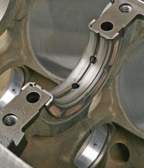
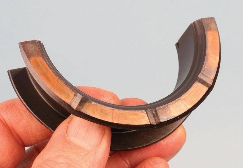
Fig. 1
Fig. 3
Fig. 5 Fig. 2
Fig. 4
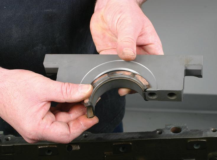
Fig. 1: Depending on engine design, the thrust bearing may be located at the center or rear main bearing area. Both the upper and lower bearing shells will feature thrust faces. Note the oil grooves on the thrust face. If these are worn off, the upper and lower bearing shells must be replaced.
Fig. 2: Example of an upper main thrust bearing at the center main location in a GM LS-series engine.
Fig. 3: Note the shallow relief on this main cap, designed to accommodate the thrust bearing.
Fig. 4: A dial indicator allows inspection of crankshaft thrust movement. The indicator plunger must be positioned parallel to the crankshaft.
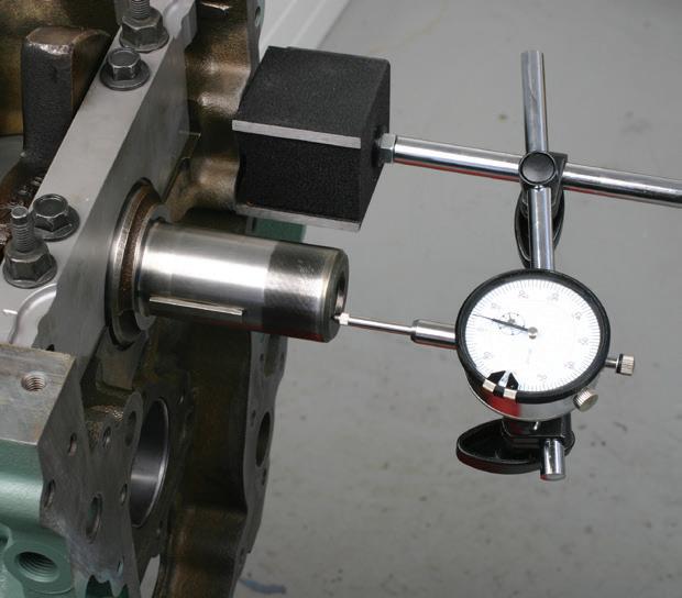
Fig. 5: An alternative for dial indicator placement is at the face of the front counterweight.
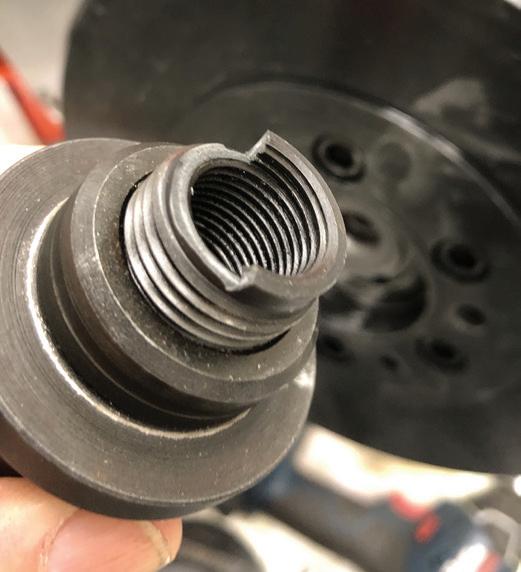
This is what happens when the adapter is not fully threaded into the tool’s mandrel.
INSTALLING HARMONIC BALANCER
When installing a harmonic balancer, always use a dedicated balancer installation tool that allows you to draw the balancer onto the crank snout. Here’s a tip: when you install the adapter (the threaded adapter that screws into the tool’s mandrel and engages into the crankshaft bolt female threads), always make sure that the adapter is fully threaded into the mandrel first. If the adapter is only installed by a few threads, the force required to draw the balancer into place can easily break the female threaded end of the mandrel. If the adapter does not thread into the mandrel easily by hand, use a screwdriver to turn the adapter (the adapter has a slot) to fully tread into the mandrel.
TORQUE/ANGLE MADE EASY
Whenever you’re dealing with tightening engine fasteners that require an OEM spec, involving both torque and angle tightening, there’s the hard way and there’s the easy way. Let’s say that a bolt (or series of bolts) requires an initial torque of 30 ft-lbs, to be followed by an additional rotation of 120 degrees. You can apply the initial torque value using your torque wrench, then lay that tool aside, then paint a dot on the bolt head and rotate it to what you assume to be about 120 degrees. Or after torque, you can grab an angle gauge, attach it to a wrench, zero it, and carefully rotate until you hit the 120-degree mark (depending on the type of gauge, this can often prove cumbersome). In either case, you must perform a continual turn and cannot use a wrench ratcheting feature. Either approach takes more time and can be inaccurate.
The best method by far is to use a digital torque wrench that also incorporates angle tightening. Press a button to select the torque type (ft-lb, in-lb or Nm), and select the torque value. Use the wrench to apply the desired torque (with most tools), when you reach the desired torque, a visual and audible alert will notify you. Next, using the same tool, press a mode button to select angle. Then select the desired angle. Place the wrench back onto the bolt head and turn, using either a continuous pull or (depending on the features of your specific digital wrench) use a ratcheting motion. Some tools feature an internal “memory” of rotation during ratcheting, which is a nice feature. The audible and visual alert will be observed when you reach the desired angle. Currently available torque/angle digital wrenches provide both speed and accuracy.
HITCH RECEIVER MAINTENANCE
It’s common for many of your customers’ light trucks or SUVs to be equipped with a frame-mounted hitch receiver. In many cases, the owner has installed a draw bar (with ball) into the receiver prior to a trip and has neglected to remove the draw bar after a trip. Leaving a draw bar installed in the receiver commonly results in rust issues, to a point where the draw bar has become severely stuck. Suggest that the owner first applies an anti-seize paste or other lube onto the draw bar before installation, and when not in use, to remove the draw bar. Periodic maintenance can avoid this problem by simply cleaning the draw bar and cleaning the receiver’s square port with a square bristle brush designed for this task. Whenever a vehicle enters the shop equipped with a receiver, ask if the owner would like to have it cleaned and lubed. Paying attention to this will avoid future headaches. A rusted-in-place draw bar can be stuck so severely that in some cases, the entire hitch receiver assembly needs to be replaced if the draw bar cannot be removed.
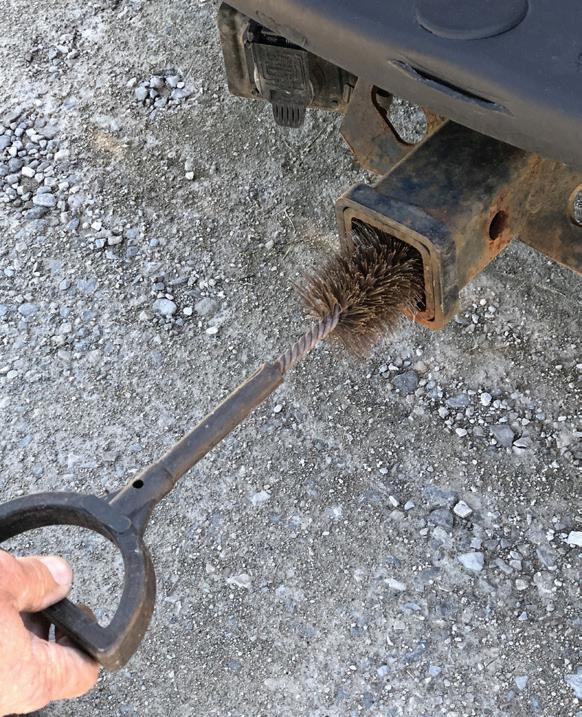
Simply cleaning a receiver with a bristle brush prior to each use can avoid big problems. Scrub to remove all rust and debris, and lube the draw bar prior to installation. Leaving a draw bar in the receiver year-round can easily cause rust seizure.