5 minute read
Revit Structure
from AUGIWORLD
by AUGI, Inc.
Modeling Stage Rigging in Revit
This month is basically going to read like a technical book. Just the way I like it. So to model rigging as shown above, follow these steps:
1. Open Revit and Under Families click New…
2. Find Generic Model, and click Open
3. Right Click on one of the green reference planes and select Create Similar.
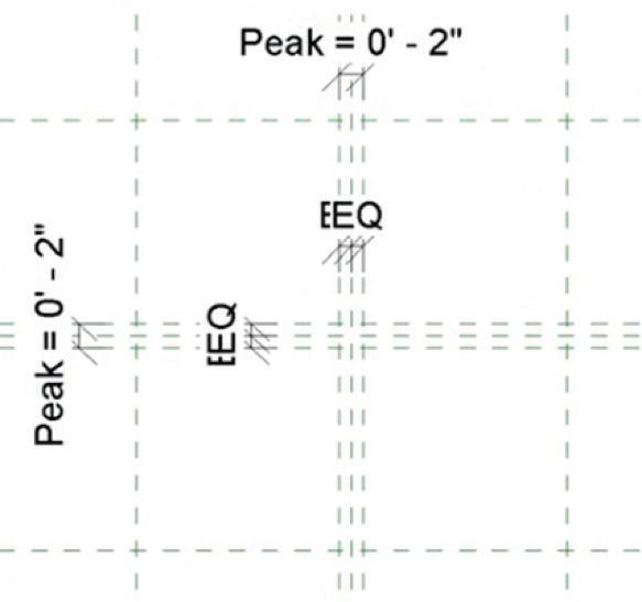
4. Offset the reference planes 1’-6” right and left then above and below as shown in Figure 1. 5. Add the dimensions and add the parameters shown in Figure 2.
6. In the Project Browser, In the Elevations (Elevation 1) category, go to the Left elevation.
7. Create a reference plane 3’-0” above the Ref Level.
8. Dimension the Reference plane starting from the level to the new reference plane
9. Add a parameter called Height.
10. Go back to the Ref. Level floor plan and create the reference planes, dimensions and parameters as shown in Figure 3.

Figure 1.

Figure 2.

Figure 3.
ADDING A SOLID BLEND
1. On the Forms Panel, click the Blend button.
2. Select the Pick Lines button and make sure the
Lock button is checked
3. Pick the outer reference planes (This will be the bottom of the Blend)
4. On the Model Panel, click Edit Top and pick the four reference planes that indicate the Peak.
5. Click the Green Checkmark for Finish Edit Mode
6. Go back to the Left elevation.
7. Align and lock the top of the blend to the top reference plane. See Figure 4.
8. Go to a 3D view
9. On the Create tab, Click the Sweep button 10. Click Pick Path
11. Pick one of the four lines connecting the base to the top
12. Click the Green checkmark
13. Draw a 2” Diameter circle and pick the red dot on the middle of the line
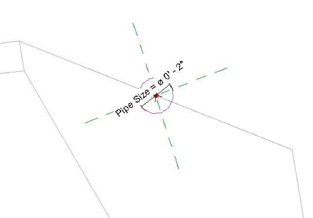
14. Add a Diameter dimension and label it Pipe Size as shown in Figure 5.
15. Do the same for the rest of the lines so there’s four pipes.
16. Select the solid Blend and uncheck Visible in the properties
17. Save the family as Truss Bars.rfa


Figure 5.
LINE BASED FAMILIES
In this portion, we will model the actual framework of our truss. Then, we will load in the Truss Bars family and create an array which will calculate the number and spacing of the bars.
1. Start a new family using the template called
Generic Model Line Based.
2. Click the Sweep button.
3. Click Sketch Path.
4. For the first point, click the left most intersection, for the second point, click the right intersection.
6. In the Project Browser, go to the Left elevation
7. Click Edit Profile
8. Add the three 4” circles, the reference planes, dimensions and parameters as shown in Figure 6.
9. Click the Green Finish checkmark button.
10. Go back to the Ref Level floor plan.
11. In the properties, change Length to 10’-0”.
12. Go to Insert, then Load Family and select your
Truss Bars family.
13. Click the Component button.
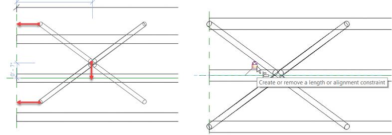
14. Hit the space bar once to flip it as shown below.
15. Place it in the model approximately where shown. Below to the left.
16. Align and lock the left side of the family to the left reference plane, and the centerline of the family to the middle reference plane as shown below to the right. 17. On the Properties panel, click the Family
Types button
18. Create the following parameter below making sure your settings are identical:
19. Now create the following parameters as instance parameters, and the Type of Parameter as length. Also add the Values and Formulas as shown:
20. Select the Truss Bars family
21. Click Edit Type
22. Click Associate Family Parameter with the corresponding parameters you just made as shown in Figure 10.

Figure 6. Figure 8.


Figure 9.

Figure 10.
CREATING THE ARRAY
Here we will tell Revit how we would like to array our nested family.
1. In the Project Browser, go to the Elevation: Front
2. Select the Truss Bars Family and click Array
3. In the options, the Number will be 2 and Move to: is 2nd .
4. Pick a point anywhere on the first family and pick a second point to the right about 4’.
5. Hit Esc. Add a dimension from the center point of the first family to the center point of the second family as shown.
6. Select the dimension and add the parameter Bar Spacing to it as shown to the left below:
7. Select the family to the right. You will see a small number 2. Select that, and add the parameter Number of Bars (Shown on the Right below).

Figure 11 You’ve done it! Load this family into a project and click Component and start drawing it. Change the overall size parameters as needed. If you need further assistance with this, let me know at ewing@ cscos.com or message me on LinkedIn, and I will give you access to my LinkedIn Learning videos which might clear some of this up!
Eric Wing lives in Syracuse NY where he is the Director of BIM Services for C&S Companies. Eric is a popular speaker at events around the country speaking on many BIM-related topics.
Eric has authored several books including Autodesk’s official training guide for their BIM solution “Revit” called Revit for Architecture No Experience Required. Eric is also an author for LinkedIn Learning where he has authored around 60 full courses on BIM management, Revit, AutoCAD MEP, Navisworks and Virtual Design and Construction (VDC)
Eric has truly been a leader in the architecture, engineering and construction industry since the conception of BIM and 3D design, and has specialty skills in BIM coordination, training and development of technical staff along with daily application of these tools on multi scale, multidisciplinary projects.
Eric is also currently a Professor at Syracuse University teaching BIM and Advanced BIM at the School of Architecture, and at the School of Engineering.
Eric has also taught courses at the Rochester Institute of Technology and Clarkson University on the subjects of Analytical tools for Facility Management, BIM, and Integrated Project Delivery.


