10 minute read
Civil 3D
from AUGIWORLD
by AUGI, Inc.
Customizing Assemblies with Subassembly Composer
Sure, you can turn a polyline into an assembly pretty quick but go to the properties to modify a depth or width and you will quickly learn while Autodesk SAC will quickly find its way into your workflow and hopefully this document will help.
WHAT IS SUBASSEMBLY COMPOSER (SAC)?
Autodesk Subassembly Composer has been available for a while. You may have no idea that it was ever even installed! Or maybe you opened it up once closed it as fast as I did the first time.
But if you really want to make yourself more productive within Civil 3D, then this is a great start.
SAC is a simple interface used to develop subassemblies for use within AutoCAD Civil 3D without the need to learn programming. The user interface is basically drag and drop from a “Toolbox” into the “Flowchart” in order to define geometry. You can add the basic building blocks of a subassembly; points, links, and shapes using SAC.
This can be a very simple process, or these can be extremely advanced, all depending on the needs of your project.

Figure 1
THE USER INTERFACE
There are 5 portions to the SAC user interface, I will briefly describe the 3 main ones below.
The Flowchart
The Flowchart panel is the workspace used to build and organize the subassembly logic and elements. A flowchart can be a simple straight line of logic, or it
can be a complex tree of decisions. The subassembly definition tree always begins with the Start element, shown below as a big green circle. If a problem is found within your subassembly, a small red circle with an exclamation point will be displayed in the upper-right corner of the problem point.
The Toolbox
The Toolbox panel is the storage location for elements available for constructing the subassembly. This panel will provide all the elements you’ll use to build your flowchart. At the simplest level, 2 or 3 elements may be used to complete a subassembly. To use any of these elements, click and hold on the desired element and drag and drop it into the Flowchart panel.
Settings & Parameters
The Settings and Parameters panel consists of several tabs that define the subassembly: • Packet Settings • Input/Output Parameters • Target Parameters • Superelevation • CANT • Event Viewer.
Packet Settings
On the Packet Settings tab, you can define the subassembly name, provide a description, link to a help file, and link to an image. The only required piece of information is the subassembly name. The name shall contain NO spaces, although it can contain dashes and/or underscores. A name like ConcreteWedgeCurbing, is an appropriate name. The subassembly name will be the name that is displayed on the tool palette once it’s imported into Civil 3D. If you include a description, this text will appear on the tool palette as a tool tip text. If you provide an image, it will display in the tool palette next to the subassembly’s name. This is not required, but helpful once imported into Civil 3D. This can be as easy an taking a snapshot of the Preview window of SAC.

Figure 2 Figure 3

CREATING YOUR PKT FILE
I thought I’d use a fairly simple example for this article, but again, these can get pretty crazy! I’ve spent anywhere from 2 hours to 48 hours building subassemblies in SAC.
I always sketch out my intended subassembly, this will be helpful in making sure you meet the standard detail you are looking for. As you draw it out, you may also think of things that may get lost while attempting to connect the dots.
A simple sketch will help. Below is an example of one of the subassemblies we will be using throughout this session.
1. If you haven’t already, launch Subassembly
Composer. 2. Save your file to the desktop, called
ConcreteValleyGutter.pkt 3. We will first start with the Packet Settings

Figure 4
• For the Subassembly Name, type in
ConcreteValleyGutter. SAC does not like spaces, but you could do underlines. • Add a description. Standard Concrete Valley
Gutter. User defines width and flowline depth. • Leave the help file and image file blank for now.
Set Input/Output Parameters
4. Refer to your hand sketch if needed. This is where we can really use some power of basic modeling within Subassembly Composer. Here we will create several parameters that we will reference as we build the valley gutter. It is best to put as many as you can up front in here, but you can always go back and Add/Remove.
• The SIDE parameter is already there. Change the default value to LEFT. • To add a parameter, click on CREATE
PARAMETER. • Rename the parameter to ConcreteWidth • Type = Double • Direction = Input • Default Value = 5
5. Create more parameters based on the image below.
NOTE: If you mess up an input, or add additional parameters, all you do is select the row, and hit the DELETE button on your keyboard.
Set Target Parameters
We will want to add in a couple Target Parameters, this could be useful when targeting an existing concrete edge and elevation. These are the same target types that you currently use in corridor modeling.
6. To add a parameter, click on CREATE
PARAMETER. • Rename the parameter to TargetOffset • Type = Offset • Preview Value = 5
7. Now let’s add one for the Elevation. Click on
CREATE PARAMETER. • Rename the parameter to TargetElevation • Type = Elevation • Preview Value = 0
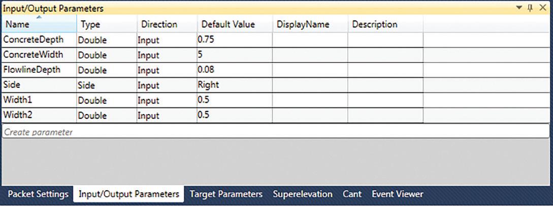
Figure 5
BUILDING OUT THE SUBASSEMBLY FLOWCHART
Every flowchart will start from the Start element.
From there, the flowchart is builds out with elements from the Toolbox, which are connected with arrows. Every element you add from the Toolbox has at least two nodes: • One node for an incoming connection arrow • One node for an outgoing connection arrow
Now let’s start dragging and dropping to see our shape take form!! 1. From the Toolbox, under the Geometry branch, drag a Point element to just below the Start element. The Start element will connect to the new Point element, which has automatically been numbered P1.
2. Select the P1 point element. Notice in Figure_06, that the properties box is no longer blank.
• You will see that it has been placed on the origin. The origin is the geometry point your subassembly will attach to when generating an assembly in Civil 3D.
3. From the Toolbox, drag another Point element to just below the P1 element. This point will be automatically numbered P2 (or P2&L1), and will represent the LEFT edge of concrete, from the top to bottom.

Figure 6
4. Define P2 as shown in Figure_06:
• Under the Point Geometry Type, ensure that
Delta X and Delta Y is selected • Under the Point Geometry Properties, Delta X will remain 0, but Delta Y needs to change. If we were to type in 0.50, we would have a static depth. By using the Input/Output Parameters that we previously set up, this will allow the user to define a depth. So for Delta Y type in –
ConcreteDepth (we do – so that the elevation goes down, not up). • Make sure, under Link, that ADD LINK FROM
POINT is checked ON.
5. From the Toolbox, drag another Point element to just below the P2&L1 element. This point will be automatically numbered P3 (or P3&L2) and will represent the width along the BOTTOM of concrete, from left to right.
6. Define P3 as shown below:
7. Take a look at the Preview window as you build your subassembly.
8. From the Toolbox, drag another Point element to just below the P3&L2 element. This point will be automatically numbered P4 (or P4&L3) and will represent the width along the BOTTOM of concrete, from left to right.
9. Define P4 as shown below (Make sure to take the negative (-) out of the ConcreteDepth)
10. From the Toolbox, drag another Point element to just below the P4&L3 element. This point will be automatically numbered P5 (or P5&L4) and will represent the width along the TOP LEFT of concrete, from left to right.
11. Define P5 as shown below (Begin from Point
P1).
12. From the Toolbox, drag another Point element to just below the P5&L4 element. This point will be automatically numbered P6 (or P5&L4) and will represent the width along the TOP RIGHT of concrete, right to left.
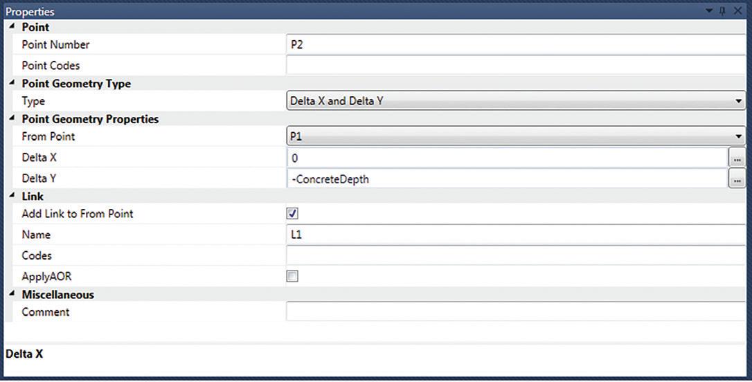
Figure 7

Figure 8 Figure 9

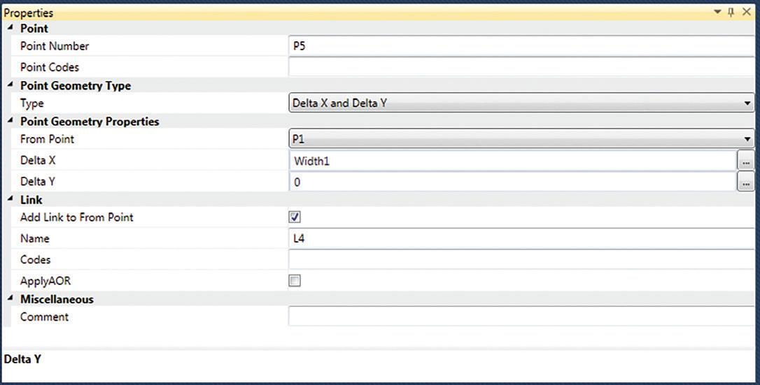
Figure 10
13. Define P6 as shown below (Begin from Point
P4).
14. From the Toolbox, drag another Point element to just below the P6&L5 element. This point will be automatically numbered P7 and will represent the FLOWLINE along the TOP of concrete.
15. We will choose to do a simple equation. So, for Delta X we want this centered in the valley gutter. We will use ConcreteWidth/2 (For half the total width).
16. Define P7 as shown below (Begin from ORIGIN).
17. This time let’s add a LINK instead of POINT.
From the Toolbox, drag a LINK element to just below the P7 element. This LINK will be automatically numbered L6 and will connect P5 to P7. 18. Define L6 as shown below.
19. From the Toolbox, drag a LINK element to just below the L6 element. This LINK will be automatically numbered L7 and will connect P6 to P7.
20. Define L7 as shown below.
21. We will finish our subassembly by creating a
SHAPE. This will be used by Civil 3D to compute material volumes.
22. From the Toolbox, drag a SHAPE element to just below the L7 element. This SHAPE will be automatically numbered S1.
23. Select the GREEN box under the Component property.
24. Hover your mouse over the Preview, once inside the shape it will highlight YELLOW. Click to activate the shape.
Congratulations!! You just finished your first subassembly. Save your file. This should look similar to the figure shown at the beginning of this article.
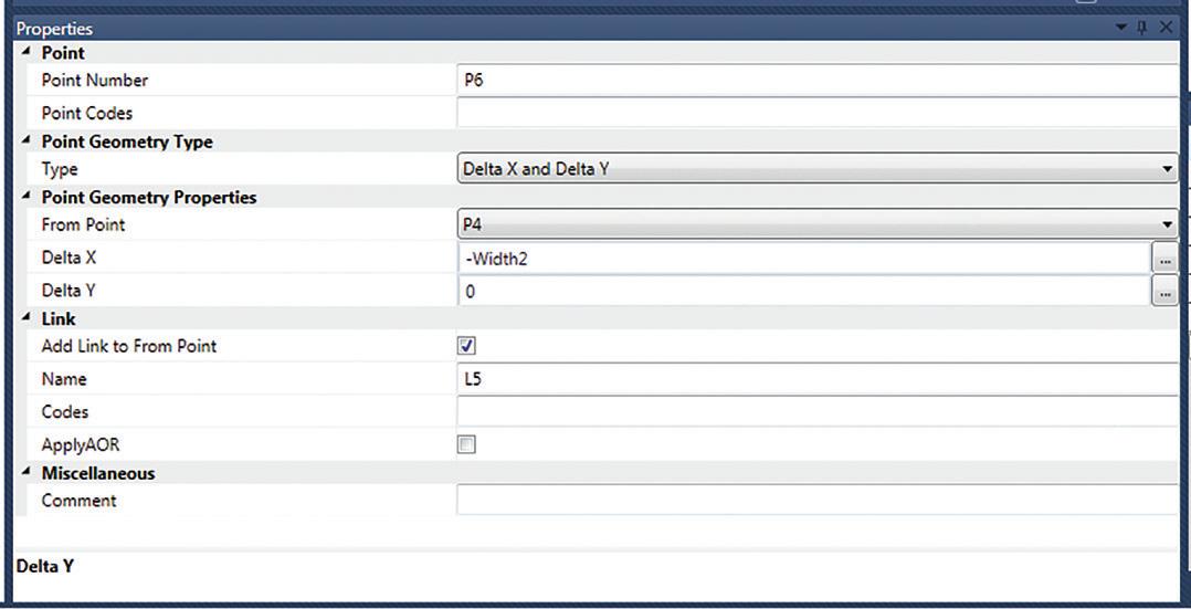
Figure 11

Figure 12 Figure 13

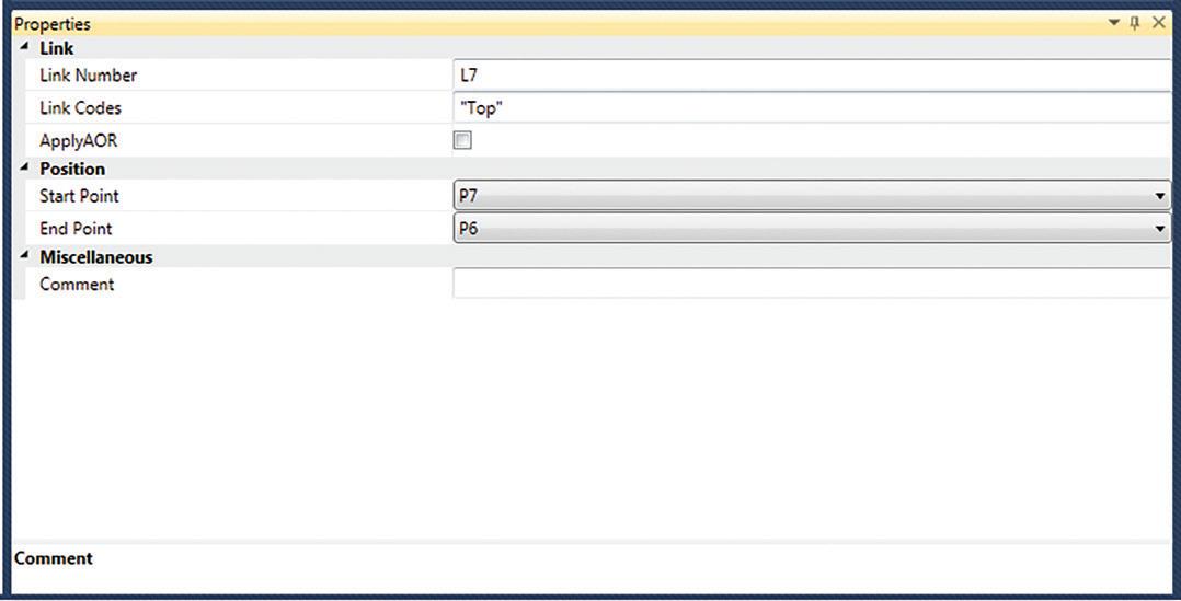
Figure 14
IMPORTING INTO CIVIL 3D
You’ve created the PKT file, now it’s time to bring it into Civil 3D. I would create a new palette to bring in your custom-built subassemblies onto.
Create a New Palette
1. Right click on the “spine” of the Subassemblies
Tool Palette and select NEW PALETTE. 2. Name the new palette, SAC – Test, or whatever you want!!

Import Subassemblies
1. Right click on your new palette and select
Import Subassemblies. 2. Brows to the file, or files, and select the ones you want to import. 3. On the Import Subassemblies dialog box, make sure you have the correct Tool Palette selected. 4. Select OK (Figure 15).
CONCLUSION
The best way I found to learn Subassembly Composer is to take some examples of a PKT file(s) that others have put together and reverse engineer the data. That got me started and is still helpful to fall back on how these are built.
If you shoot me an email, I can send some I have built, along with some more advanced steps in using more of the tools that SAC has to offer.
Thank you!
Shawn has been a part of the design engineering community for roughly 15 years in all aspects of design, construction and software implementations. He has implemented and trained companies across the Country on Civil 3D and other infrastructure tools and their best practice workflows. Shawn can be reached for comments or questions at sherring@ prosoftnet.com.


