


Door Switches
Door Lock Switches
Flat Type Door Lock Switches
Non-Contact Door Switches
SFD
SFDL
SFDL2
SFN Series
Emergency Stop Button Switches
Grip Type Enabling Switches Key Selector Switches
SF2ER Series
SFEN Series
SF2KR Series


Door Switches
Door Lock Switches
Flat Type Door Lock Switches
Non-Contact Door Switches
SFD
SFDL
SFDL2
SFN Series
Emergency Stop Button Switches
Grip Type Enabling Switches Key Selector Switches
SF2ER Series
SFEN Series
SF2KR Series
“Safety” is becoming an essential part in industrial automation, and the two parts are very closely associated. New safety standards have become mandatory in many industrial fields, to protect personnel from injury in potentially dangerous areas or situations. Automation technology is changing rapidly, with increased chance of injury from dangerous machinery.
Safety system can be applied in almost all industrial fields where people and machines must co-exist. By implementing safety systems, companies can ensure safe environments for workers, reduce costs from health risks and increase work efficiency. Safety system is no longer a choice to make, it has become an essential requirement.
Autonics is proud to introduce various safety products to ensure safety in industrial sites. With automation technology and expertise which we have built for over 40 years, we now present new safety products that will protect you and your equipment.
Autonics safety solution promises to keep you safe and raise workplace efficiency with stable, reliable, flexible, and practical safety products and systems.



Safety is a top concern in industries where personnel and machines must work together. As a partner to keep you and your machines safe, Autonics offers various safety technology and solutions.
utonics safety products feature high flexibility and practicality, with various product options and functions that can be applied in various different environments. Our products are developed to meet customer needs and demands in the industry and also to increase workplace e ciency.
With Autonics safety solutions, you can minimize various risks and prevent accidents by analyzing environmental and operational settings. Ensure peace of mind at your operation sites by choosing Autonics safety products. We will keep you safe.


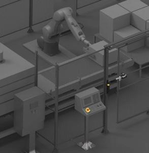
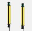


Standard Type SFL Series
High Performance Type SFLA Series
Emergency Stop Button Switches SF2ER Series
Grip Type Enabling Switches SFEN Series
Key Selector Switches SF2KR Series
Relay Terminal Blocks SFT Series



Door Switches SFD Series
Door Lock Switches SFDL Series
Flat Type Door Lock Switches SFDL2 Series
Non-Contact Door Switches SFN Series
Standard Unit SFC
High Performance Unit SFC-A
Non-Contact Door Switch Unit SFC-N
xpansion elay nit SFC-ER
Relay Unit SFC-R
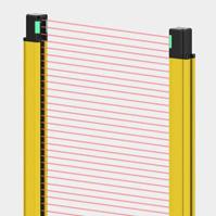
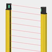
Safety light curtains are installed in potentially dangerous or hazardous areas or machines to safeguard personnel from injury. Operation of potentially dangerous machines are turned off when an object or person is detected between the emitter and receiver. The light curtains feature proven technology from Autonics area sensors and mapping sensors. The light curtains are built to meet international safety standards and regulations. Various detection models and safety functions are available to protect your safety diverse applications.


Safety Standards
IEC/EN 61508 (SIL 3)
IEC/EN 62061 (SIL CL 3)
EN/IEC 61496-1/2 (Type 4, A.O.P.D., E.S.P.E.)
ISO 13849-1/2 (Cat. 4, PL e)
Certifications

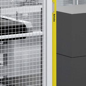
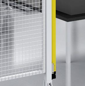


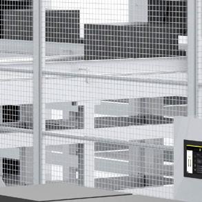


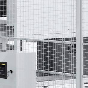


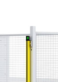
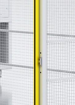
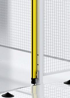
The SFL/SFL series safety light curtains are available in various models for flexible application. The light curtains are available in various product heights, beam pitch size (9 mm/15 mm/25 mm) for installation in diverse environments. The light curtains can be expanded to sets and beams for application in larger scale industrial environments.
Finger detection, hand detection, hand-body detection models are available for application in diverse user environments.
Finger detection type

Hand detection type
Body detection type
- Beam pitch : 9 mm - Minimum detection size : Ø14 mm - Beam pitch : 15 mm - Minimum detection size : Ø20 mm - Beam pitch : 25 mm
Minimum detection size : Ø30 mm
SFL Series (Standard Type)
Sensing distance (Long mode) 0.2 to 10 m0.2 to 15 m0.2 to 15 m Detection
Ø 14 mmØ 20 mmØ 30 mm Optical axis pitch 9 mm 15 mm 25 mm Number of beams 15 to 111 ea12 to 68 ea42 to 75 ea
144 to 1,008 mm183 to 1,023 mm1,043 to 1,868 mm
SFLA Series (High Performance Type)
Hand Body
Sensing distance (Long mode) 0.2 to 10 m0.2 to 15 m0.2 to 15 m Detection
Ø 14 mmØ 20 mmØ 30 mm Optical axis
9 mm 15 mm 25 mm Number of
15 to 199 ea12 to 124 ea9 to 75 ea
144 to 1,800 mm183 to 1,863 mm218 to 1,868 mm

2. Various Protection Height
Various models are available by protection height (144 mm to 1,868 mm), offering options for diverse equipment sizes


Long sensing distance (15 m) allows wider area of detection. The sensors can be set to short/long mode depending on user needs.
- Short Mode : 0.2 to 5 m / 0.2 to 8 m
- Long Mode : 0.2 to10 m / 0.2 to15 m


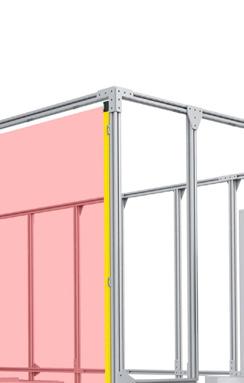
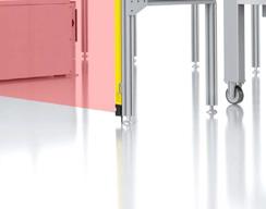


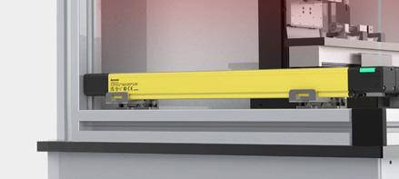
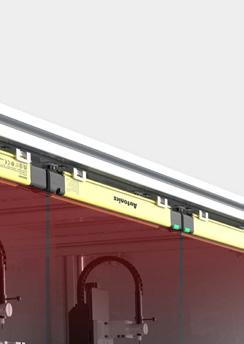
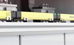
The SFL series light curtains can be expanded up to sets and beams with serial expansion cables. ultiple light curtains can be controlled using a single connection line, offering easier wiring, installation, and design planning.
Also, the mutual interference protection ensures that there is no signal interference between the connected units. If an error is detected in a single unit, all connected units will enter into lockout state.


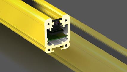
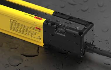
The SFL/SFLA series is designed with hardened casing and screen protection for application in harsh conditions. The light curtains can be installed in environments with impact, dust, or moisture.



1.
The robust body housing allows stable operation in harsh conditions with sudden impact.
2. Window Screen Protection
The narrow window screen with protection minimizes the chance of impact to the sensing areas.
3. IP65/IP67/IP67G/IP69K Protection Rating
IP65/IP67/IP67G/IP69K protection
structure allows the units to be safely applied in environments with dust or water.
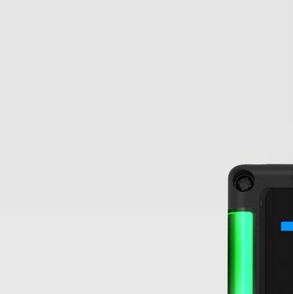
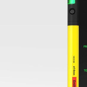
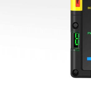
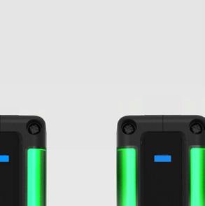
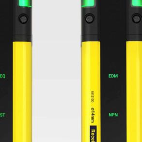
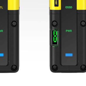


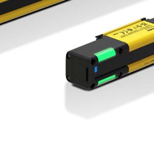
Top beam indicator lights up top beam is received
Top control output indicator lights up or flashes depending on control output
Power/lockout indicator lights up when powered on or normal operation
Bottom beam indicator lights up when bottom beam is received
Frequency indicator lights up with frequency B setting / turned off with frequency A setting
External test indicator lights up when external test signal is applied
Interlock indicator lights up when during interlock state
EDM indicator lights up with EDM input
NPN/PNP indicator lights up with NPN setting/turned off with PNP setting
Control output indicator green light when output ON, red light when output OFF
Status display indicates operation status


The SFL/SFLA series is designed to provide a sense of safety to users. The large operation indicators offer minimal blind spots, and operators can easily check the status of the light curtains in real-time, ensuring safety of both personnel and machines.
The top control output indicator shows various output status including output ON/OFF, muting/override status, lockout status etc. The indicator is located on the top corner of the unit, which make it highly visible from any angle.

The 7-segment status display shows various operation status of the unit using alphabet or numbers. Users can check various status including error status, communication status, warning conditions, etc.

Status Display Description
Location
OperationDisplayDescription
PC connection (download) P Flashing Flashes when downloading the setting information.
Communication error C Flashing Flashes when RS485 communication error occurs.
Emitter / Receiver
Error condition E Flashing Flashes when entering the lockout condition.
Warning condition A Flashing Flashes when in a warning condition.
Default condition 0 ON Displays when function is deactivated.
Blanking B ON Displays when the blanking function is activated.
Muting M ON Displays when in the muting state.
Emitter
Override O ON Displays when in the override state.
Reset-hold H ON Displays when waiting for reset-hold input.
Reduced resolution R ON Displays when the reduced resolution function is activated.
Receiver Light incident 0 9 ON Displays the sensitivity level of beams with the lowest light incident (0 to 9).
3. Beam Indicator
The LED beam indicator turns blue when the beam is received normally, and turns off when the light is blocked.
The LED turns red when ambient light is received. The indicator allows easy installation and setting, and also provides users with visual indication of errors.
The indicator can detect misalignment of emitter and receiver in real-time, allowing easier installation and setting.
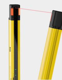
❶ Align the top beam
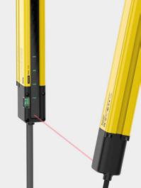
❷ Align the bottom beam
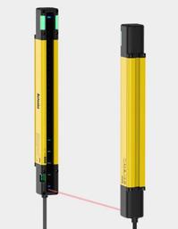
❸ If the LED indicator turns blue, the beams have been aligned normally.
2) Check Light Sensitivity
The sensitivity reduction alarm is activated if the amount of light received changes due to vibration, heating, distortion, or other factors preventing problems in advance.
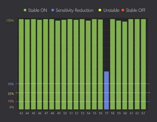
3) Check Ambient Light
mbient light alarm is activated if external ambient light is detected or if emitter/receiver operation timing is affected.
(Ambient light algorithm)
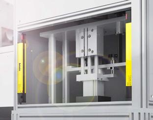
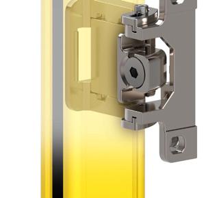
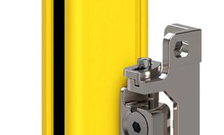
The SFL/SFLA series features easy installation. Standard and ad ustable brackets are available and can be installed on top, bottom, or middle of the units.
The ad ustable brackets can be ad usted by degrees to right or left for easier installation.
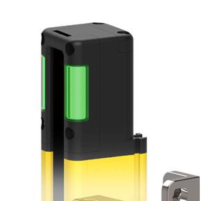
One-Touch Bracket
The push-to-install one-touch method allows easier installation.
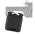
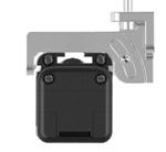
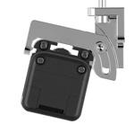
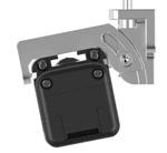
Adjustable Brackets
The ad ustable brackets can be ad usted by degrees to right or left after installation for easier setting.
Brackets by Light Curtain Length
Length
Brackets Max. 1 mMin. 1 m
Top/Bottom adjustable bracket (BK-SFL-TBA) Requires 2 brackets Unavailable
Top/Bottom bracket (BK-SFL-TBF)
Side adjustable bracket (BK-SFL-SA) Requires 2 brackets Requires 3 brackets
Side bracket (BK-SFL-SF)


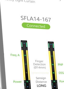
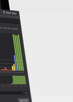
atLightCurtain is a dedicated software for SFL/SFLA series safety light curtains to monitor operation status and set functions Users can set various safety-related functions including muting, blanking from the parameter menu and monitor various operation status including light amount, connection, and errors.
※ Detailed settings and features may not be available on standard type SFL series.

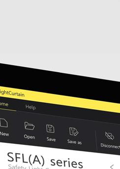


The atLightCurtain software screen features ribbon menus with status display, monitoring, and setting screens. The intuitive icons and user-oriented interface allows even novice users to easily operate the software. The setting and monitoring screens can be expanded to show diverse range of information.
Ribbon menu main software functions
Status display screen product information and operation status
Monitoring and setting screen product connection and monitoring information, safety functions
Monitoring light level by beam, connection, errors/alarms, etc.
Safety-related functions model settings, muting, blanking, and other settings

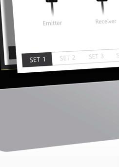


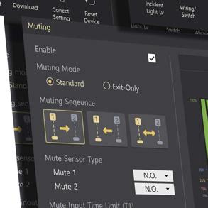
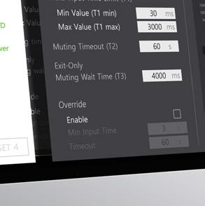


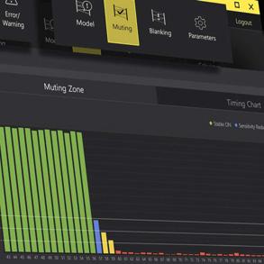




Industrial settings vary greatly by size and type, and potential dangers can occur from various environmental factors.
Users can set muting, blanking, and other safety-related functions on the SFLA series with the atLightCurtain software.
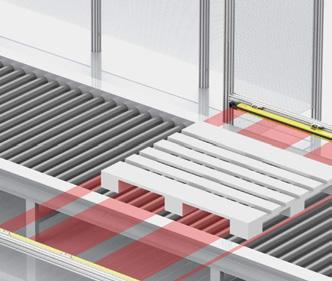


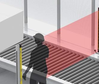


Reduced resolution is a function for changing the detection capability of the light curtain. It prevents the control output from turning OFF when an ob ect moving through the light curtain is smaller than the designated size. Reduced resolution can be set for all areas within the detection area, and up to 3 beams can be set to be ignored.
Muting function is a function to prevent the control output from turning OFF when an ob ect is detected moving through the curtain. The light curtains can be set so that machines will stop operation only when a person is detected by muting the beams where ob ects may pass. The muting area can be set for the entire detection area or only for selected areas.
Standard Mode Default muting function that starts and ends muting status by the set conditions.
Exit-Only Mode Maintains muting status until object has completely cleared the area.
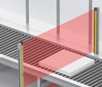

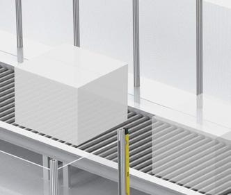


Blanking function allows users to set selected beams blanking zones, preventing detection of ob ects in the blanking zone. This function can be used if an ob ect or machine is located within the detection area, partially blocking some beams.
Blanking Function Types
Fixed Blanking Used when an object or machine is continuously blocking certain beams.
Floating Blanking Used when an fixed-sized object is moving. The blanking area changes with the moving object.
Override function is used when the muting function ends and operation resumes, but the ob ect is still within the detection area. The override function can be used to turn output ON to remove the ob ect in the moving direction.

Choose the correct light curtain model by following the directions below.
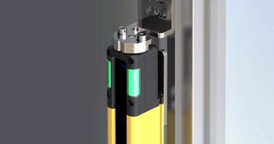
Select model by purpose of use.
- 1 2 3
SafetyLight CurtainTypeDetection CapabilityNumber of Beams
Select type
Select standard or high performance type depending on required needs.
Classification Function SFL Series (Standard type) SFLA Series (High performance type)
Mode and status
Self-test
RS485 communication (between emitter and receiver)
General functions
Monitor light incident level
OSSD output
Mutual interference prevention
Interlock
Lockout reset
External device monitoring (EDM)
Safetyrelated functions
Muting
Override
Blanking (Fixed blanking and floating blanking) X
Reduced resolution X
Series connection
Select sensing distance
Select NPN or PNP
Other functions
External test (light emission stops)
Auxiliary output (AUX)
Lamp output (Lamp)
PC connection Type No-mark A
2
1 Select detection capability
Select the detection capability type. nger, hand, body
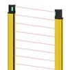
Select number of beams
Select the number of beams by detection capability.
Finger detection type
Hand detection type
Body detection type

Power I/O cables (cable connector type)
M12 Connector cables (socket type)


M12 Connector cables (socket-plug type)


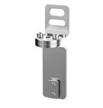
Top/bottom adjustable brackets
BK-SFL-TBA
Adjustable type
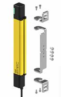
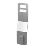
Top/bottom brackets
BK-SFL-TBF
Standard type
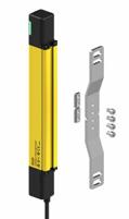
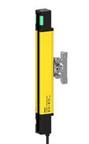
※ Safety Light Curtains Accessory (Sold Separately)
* LOTO (Lockout-Tagout) Device, SFL-LT / SFL-LT2
* SFL-LT protects worker safety through a lockout function that forcibly blocks the optical axis to maintain the interlock condition of the light curtains.
Mid-area adjustable brackets
BK-SFL-SA
Mid-area brackets
BK-SFL-SF
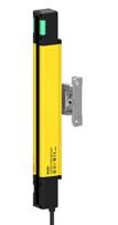


Unit: mm, For the detailed dimensions of the product, follow the Autonics web site. This dimension is based on the SFL(A) 14 model. The appearance varies depending on the detection capability.
This is only for reference. For selecting the specific model, follow the Autonics web site.
❶ Type
No-mark: Standard type
A: High performance type
❷ Detection capability
14: Ø 14 mm, finger
20: Ø 20 mm, hand
30: Ø 30 mm, hand-body
❸ Number of optical axes
Number: Number of optical axes
❹ Korea safety certification
No-mark: S-mark
A: KCs (industrial robot protection device)
※ Sold Separately
• Power I / O cable : SFL-BCT(R), SFL-C T(R)
• M12 connector cable: CID8- T(R), C1D8- T(R)
• Y type connector cable: SFL-YC, SFL-YCR
• Series connector cable: SFL-EC T(R)
• Lamp output cable: SFL-LC
• Bracket: BK-SFL-
• SFL / SFLA dedicated USB to Serial communication converter: SCM-SFL
• Test piece: SFL-T
• LOTO (Lockout-Tagout) device: SFL-LT
01) When removing the end cap, there is the lamp output terminal (top) or the power supply terminal (bottom).
02) When removing the front cover, there is the setting switch (on the emitter and the receiver) or the PC communication port (on the receiver).
Ø 14 mm (finger)
Ø 20 mm (hand)
Ø 30 mm (hand-body)
to 111144 to 1,008126 to 990 9
to 199144 to 1,800126 to 1,782
to 68183 to 1,023165 to 1,005 15
to 124183 to 1,863165 to 1,845
Type Standard type
Models SFL14-□-□ SFL20-□-□ SFL30-□-□
Sensing type Through-beam
Light source Infrared LED (855 nm)
Effective aperture angle (EAA) Within ± 2.5 ° when the sensing distance is greater than 3 m for both emitter and receiver.
Sensing distance Short - Long mode (setting switch)
Short mode 0.2 to 5 m 0.2 to 8 m 0.2 to 8 m
Long mode 0.2 to 10 m 0.2 to 15 m 0.2 to 15 m
Detection capability Ø 14 mm (finger) Ø 20 mm (hand) Ø 30 mm (hand-body)
Detection object Opaque object
Number of optical axes 01) 15 to 111 12 to 68 42 to 75
Protective height144 to 1,008 mm183 to 1,023 mm1,043 to 1,868 mm
Optical axis pitch9 mm 15 mm 25 mm
Series connection Max. 3 SET (≤ 300 optical axes)
01) It may differ depending on the models. For more information, see the "SFL/SFLA User Manual."
Power supply 24 VDC ± 20 % (Ripple P-P: ≤ 10 %)
Current consumption 01) Emitter: ≤ 106 mA, receiver: ≤ 181 mA
Safety related output : OSSD output
Type Advanced type
Models SFLA14-□-□ SFLA20-□-□ SFLA30-□-□
Sensing type Through-beam
Light source Infrared LED (855 nm)
Effective aperture angle (EAA) Within ± 2.5 ° when the sensing distance is greater than 3 m for both emitter and receiver.
Sensing distance Short - Long mode (setting switch or atLightCurtain)
Short mode 0.2 to 5 m 0.2 to 8 m 0.2 to 8 m
Long mode 0.2 to 10 m 0.2 to 15 m 0.2 to 15 m
Detection capability Ø 14 mm (finger) Ø 20 mm (hand) Ø 30 mm (hand-body)
Detection object Opaque object
Number of optical axes 01) 15 to 199 12 to 124 9 to 75
Protective height144 to 1,800 mm183 to 1,863 mm 218 to 1,868 mm
Optical axis pitch9 mm 15 mm 25 mm
Series connection Max. 4 SET (≤ 400 optical axes)
NPN or PNP open collector Load voltage 02): ON - 24 VDC (except for the residual voltage), OFF - 0 VDC , Load current 03): ≤ 300 mA, Residual voltage 04) ≤ 2 VDC (except for voltage drop due to wiring), Load capability: ≤ 2.2 , Leakage current: ≤ 2.0 mA, Wire resistance of load: ≤ 2.7 Ω
Auxiliary output (AUX 1/2) 05) NPN or PNP open collector Load voltage: ≤ 24 VDC , Load current: ≤ 100 mA, Residual voltage: ≤ 2 VDC (except for voltage drop due to wiring)
Lamp output (LAMP 1/2) 05) NPN or PNP open collector Load voltage: ≤ 24 VDC , Load current: ≤ 300 mA
Reset input, mute 1/2 input, EDM, external test
External input
Protection circuit
Safety-related functions
General functions
Others functions
Synchronization type
When setting NPN output ON: 0 - 3 VDC , OFF: 9 - 24 VDC or open, short-circuit current: ≤ 3 mA When setting PNP output ON: 9 - 24 VDC , OFF: 0 - 3 VDC or open, short-circuit current: ≤ 3 mA
Reverse power polarity, reverse output polarity, output short-circuit over-current protection
Interlock (reset hold), external device monitoring (EDM), muting/override, Blanking (fixed blanking, floating blanking), reduced resolution
Self-test, alarm for reduction of incident light level, mutual interference prevention
Change of sensing distance, switching to NPN or PNP, external test (light emission stops), auxiliary output (AUX 1, 2), lamp output (LAMP1, 2)
Timing method by RS485 synchronous line
Insulation resistance ≥ 20MΩ (at 500 VDC megger)
Noise immunity ± 240 VDC the square wave noise (pulse width: 1μs) by the noise simulation
Dielectric strength 1,000 VAC 50/60 Hz for 1 minute
Vibration 06) 10 mm double amplitude at frequency of 5 to 150 Hz, 10 sweeps in each X, Y, Z direction
Shock 06) 250 m/s2 (≈ 25 G), pulse width 6 ms in each X, Y, Z direction for100times
Ambient illumination (receiver) Incandescent lamp: ≤ 3,000 lx, sunlight: ≤ 10,000 lx
Ambient temperature -30 to 60 , storage: -30 to 70 (no freezing or condensation)
Ambient humidity 35 to 85 %RH, storage: 35 to 95 %RH (no freezing or condensation)
Protection rating 07) IP65, IP67 (IEC standard), IP67G (JEM Standard), IP69K (DIN standard)
Material
Case: Aluminum, Front cover and sensing part: Polymethyl methacrylate, End cap: polycarbonate, Power I/O cable and connector cable: polyurethane (PUR) or polyvinyl chloride (PVC), Y type connector cable: polyvinyl chloride (PVC), lamp output cable and series connector cable: polyurethane (PUR), Top / Bottom adjustable bracket and Top / Bottom bracket: SUS304, Side adjustable bracket and Side bracket: nickel plated Zn
Approval ᜢ ᜨᜪ (industrial robot protection device) 08)
International standards
UL 508, CSA C22.2 No. 14, ISO 13849-1 (PL e, Cat. 4), ISO 13849-2 (PL e, Cat. 4), UL 61496-1 (Type 4, ESPE), UL 61496-2 (Type 4, AOPDs), IEC/ EN 61496-1 (Type 4, ESPE), IEC/EN 61496-2 (Type 4, AOPDs), IEC/EN 61508-1~-7 (SIL 3), IEC/EN 62061 (SIL CL 3)
01) It may differ depending on the models. For more information, refer to the "SFL/SFLA User Manual."
02) The values of load voltage were drawn with PNP output, and in case of NPN output, apply these in reverse.
03) Be sure that the load current should be greater than 6 mA.
04) The residual voltage was drawn with 300 mA of load current.
05) It is the non-safety output. Do not use it for safety purposes.
06) Testing according to IEC 61496-1 standards.
07) Approved certification protection ratings are IP65 and IP67.
08) The certified models for S-mark and KCs (industrial robot protection device) have the same functional basis.
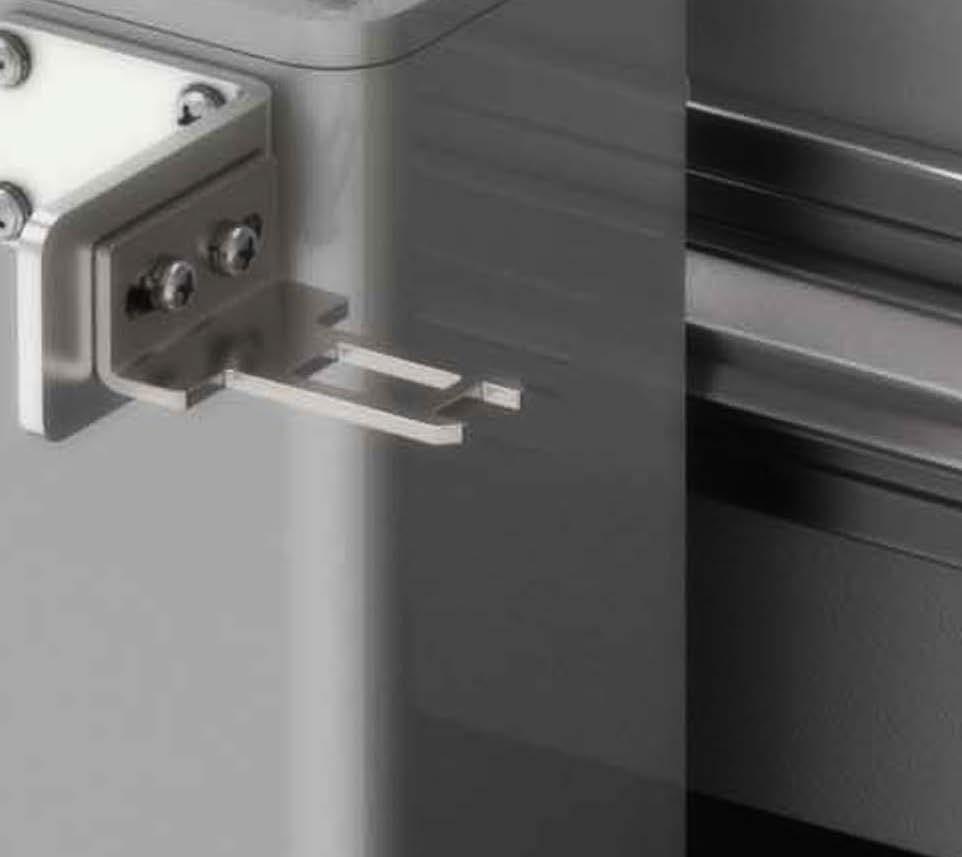
The SFD series safety door switches can detect opening and closing of doors in machines. The head can be rotated to change the insert direction of the operation key from 5 directions, with 6 available operation key types. Also, the door switches are available in terminal type and connector type models, making it easier for installation in diverse application settings.

Safety Standards
IEC/EN 60947-5-1
EN ISO 14119
GB/T 14048.5
Certifications

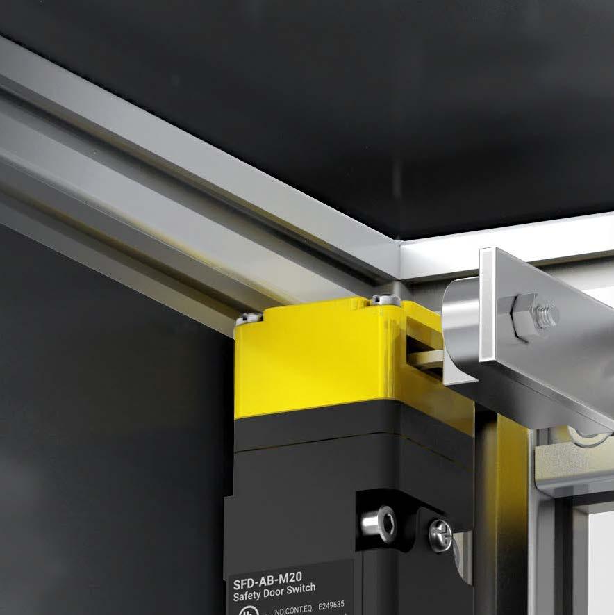
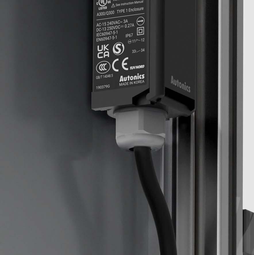


The SFD series door switches are available in terminal type and connector types for easy application and installation in diverse environments.
The SFD series offers diverse installation methods for flexible installation. The head can be rotated to change the insert direction of operation keys.
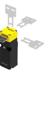
6 Operation Key Types

Connector type and terminal type models are available for application in various environments. Both types can be detached easily from the body, for easier installation and maintenance.

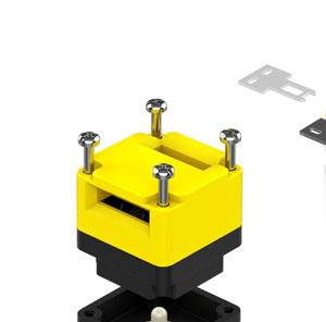

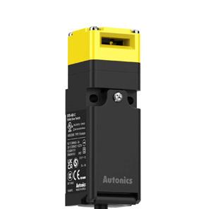

Connector Type
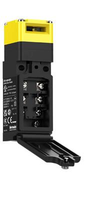
Terminal Type

The door switches are slim and compact in size 2 x D mm , allowing installation in tight or limited spaces.


2-contact or 3-contact switches are built in, with 4 types of contact con gurations for easier application in any environment. ※
※ Sold separately :
* Group lock device, connecting cable
* Group lock device is an accessory for safety door and door lock switches, to prevent actuator operation from unauthorized access by physically blocking switch insertion area.
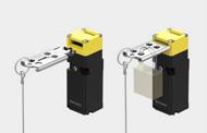
This is only for reference. For selecting the specific model, follow the Autonics web site.
Dimensions
Unit: mm, For the detailed dimensions of the product, follow the Autonics web site.
■ Connector type
❶ Head materials
No mark: Plastic
M: Metallic
❷ Contact composition
AB: 1 N.O., 1 N.C.
2B: 2 N.C.
A2B: 1 N.O., 2 N.C.
3B: 3 N.C.
❸ Connection outlet No mark: 1
2: 2
❹ Connection outlet specification
M20: M20 thread
G1/2: G1/2 thread
C: M12 connecter
※ Sold Separately
• Operation key: SFD-K
• M12 Connector cable: C DH4- -
• Group lock device: SFD-LT / connecting cable: SFD-LT-C
1 connection outlet terminal type
•1 connection outlet
is installing spot of protrusion for fixing the switch firmly.
Model SFD-□□-□M20SFD-□□-□G1/2SFD-□□-C
Rated voltage/ current for load
Resistive load: 6 A/250 VAC 0.6 A/250 VDC
Inductive load (IEC): AC-15 3 A/240 VAC DC-13 0.27 A/250 VDC
Inductive load (UL): A300, Q300
Directing opening force ≥ 80 N
Directing opening distance ≥ 10 mm
Operating speed 0.05 to 1 m/s
Operating frequency ≤ 20/min
Insulation resistance ≥ 100 MΩ (500 VDC megger)
Contact resistance ≤ 50 mΩ (initial value)
Impulse dielectric strength
Between the terminals: 2 kV (IEC 60947-5-1) Between each terminal and non-live part: 5 kV (IEC 60947-5-1)
Conditional short circuit current 100 A
Life cycle Electrical: ≥ 100,000 operations (240 VAC 6 A) Mechanical: ≥ 1,000,000 operations
Vibration (malfunction) 0.75 mm amplitude at frequency of 10 to 55 Hz in each X, Y, Z direction for 10 min
Shock 1,000 m/s2 (≈ 100 G) in each X, Y, Z direction for 3 times
Shock (malfunction) 300 m/s2 (≈ 30 G) in each X, Y, Z direction for 3 times
Ambient temperature -30 to 70 , storage: -40 to 70 01) (no freezing or condensation)
Ambient humidity 35 to 90 %RH , storage: 35 to 90 %RH (no freezing or condensation)
Protection structure IP67 02) (IEC standard, except for head)
Material Plastic head - polyamide 6, metallic head - zinc case: polyamide 6, operation key: stainless steel 304
Approval
Connection type M20 connector cableG1/2 connector cableM12 plug connector
Unit weight (packaged)
01) UL approved ambient temperature: 65
02) Rated protection structure is for the switch body. Be cautious about preventing the head part from entering the foreign materials such as dust and water.
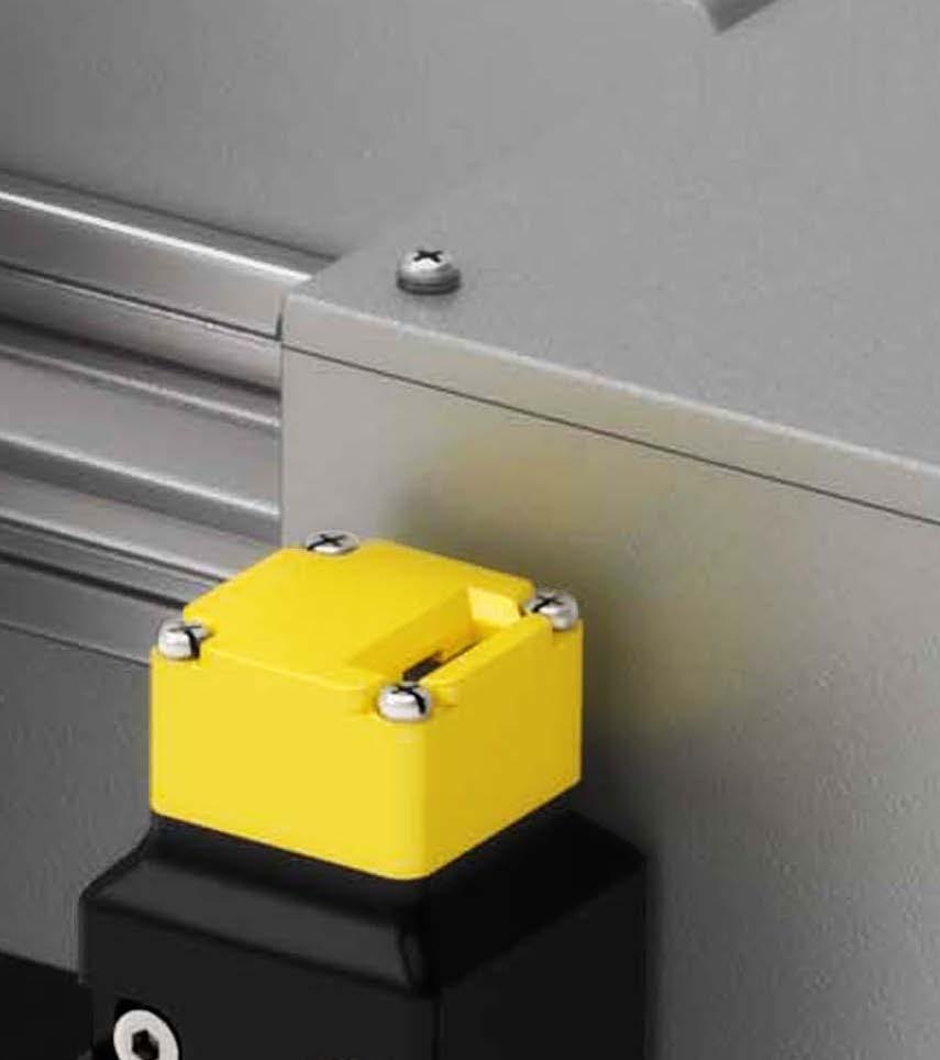
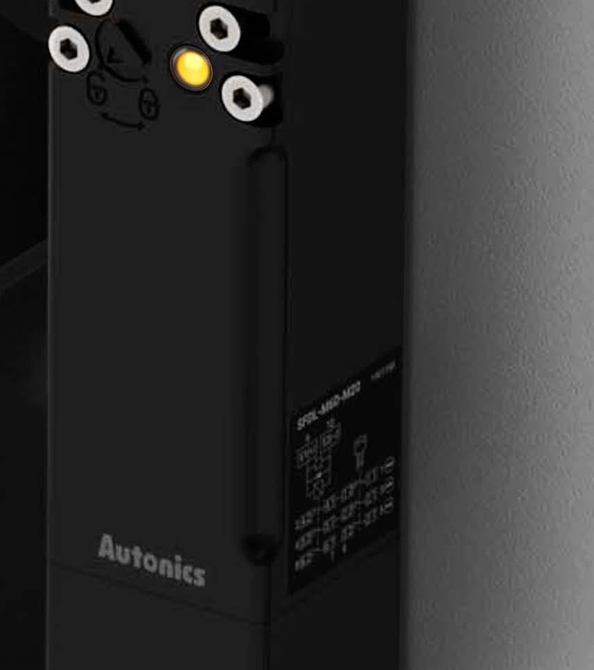


The SFDL series safety door lock switches can detect opening and closing of doors in machines, and also keep the door locked during potentially dangerous operation. The head can be rotated to change the insert direction of the operation key from 5 directions, with 6 available operation key types. Various types of connection and release keys are also available, making it easier for installation in diverse application settings.
Safety Standards
IEC/EN 60947-5-1
EN ISO 14119
GB/T 14048.5
Certifications
The SFDL series door lock switches are available in terminal type and connector types for easy application and installation in diverse environments.
The SFDL series offers diverse installation methods for flexible installation. The head can be rotated to change the insert direction of operation keys.
Terminal type and connector type models are available for application in various environments. Both types can be detached easily from the body, for easier installation and maintenance.
6 Operation Key Types Connector Type
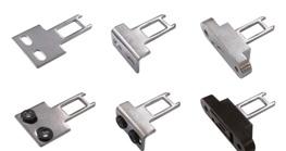
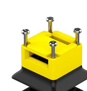

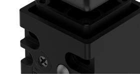


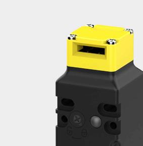
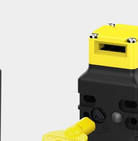

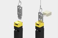
Cross type and special type release keys are available for wider options. Release keys can be used to manually unlock the units during emergency or product malfunction. The metallic release levers offer high durability.
Two types of lock/release methods are available (Mechanical lock & solenoid release / solenoid lock & mechanical release). The mechanical lock remains locked when the operation key is inserted and unlocks with solenoid power. The solenoid lock remains locked with solenoid power and unlocks when solenoid power is cut off.
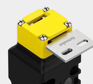
5. Powerful Lock Strength
Powerful lock strength of 1,300N ensures that the unit will remain locked under most conditions.
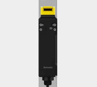
6. Slim and Compact Size
The door lock switches are slim and compact in size (H 155 x D mm , allowing installation in tight or limited spaces.
onnector type x D mm , Terminal blocks type x D mm
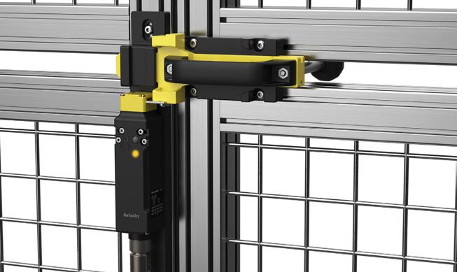
Slide Unit (Sold Separately)
The slide unit (SFDL-SD) is an accessory to prevent being locked when entering the fence using safety flat type door lock switches.
4-contact, 5-contact, or 6-contact switches are built in, with 16 types of contact con gurations for easier application in any environment.
9E1(+)10
※ Sold separately :
* Group lock device, connecting cable
* Group lock device is an accessory for safety door and door lock switches, to prevent actuator operation from unauthorized access by physically blocking switch insertion area.
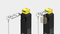
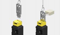
❶ Lock/Release method
M: Mechanical Lock/ Solenoid Release
S: Solenoid Lock/ Mechanical Release
❸ Contact composition
This is only for reference. For selecting the specific model, follow the Autonics web site. 4-contact 5-contact 6-contact
A
❷ Contact No-mark: 4-contact (connected)
C: 4-contact (not connected)
5: 5-contact 6: 6-contact
❹ Connection type
No-mark: Terminal type
C: Connector type
❻ Release key type
No-mark: Cross type
K: Special type
※ Sold Separately
• Operation key: SFD-K
• Connector cable: SFDL-CND10-
❺ Connection outlet specification
M20: M20 thread
G1/2: G1/2 thread
• Safety door lock slide key unit: SFDL-SDK
• Safety door lock slide unit: SFDL-SD
• Group locking device: SFD-LT / Connecting cable: SFD-LT-C
Unit: mm, For the detailed dimensions of the product, follow the Autonics web site.
Terminal type
Model SFDL-□□□-□□ SFDL-□□□-C
Directing opening force ≥ 80 N
Directing opening distance ≥ 10 mm
Locking pullout strength ≥ 1,300 N
Operating speed 0.05 to 1 m/s
Operating frequency ≤ 20/min
Mechanical life cycle ≥ 1,000,000 operations (20/min)
Vibration (malfunction) 0.35 mm amplitude at frequency of 10 to 55 Hz in each X, Y, Z direction for 10 min
Shock 1,000 m/s2 (≈ 100 G) in each X, Y, Z direction for 3 times
Shock (malfunction) 80 m/s2 (≈ 8 G) in each X, Y, Z direction for 3 times
Ambient temperature -10 to 55 01), storage: -25 to 65 (a non freezing or condensation environment)
Ambient humidity 35 to 85 %RH , storage: 35 to 85 %RH (a non freezing or condensation environment)
Protection structure IP67 02) (IEC standard, except for head)
Material Head: zinc, case: polyamide 66, operation key: stainless steel 304
Approval
Accessory SFDL- □- K (Special type release key) : rotating key
Applicable cable AWG22Connection type Terminal type Connector type
Unit weight (packaged) ≈ 375 g (≈ 440 g) ≈ 325 g (≈ 395 g)
01) UL approved ambient temperature: 50 02) Rated protection structure is for the switch body. Be cautious about preventing the head part from entering the foreign materials such as dust and water.
Contact block
Rated voltage/ current for load
Impulse dielectric strength
Resistive load: 1 A/120 VAC , 0.22 A/125 VDC
Inductive load (IEC): AC-15 1 A/120 VAC , DC-13 0.22 A/125 VDC
Inductive load (UL): C150, R150
Between the terminals of same polarity: 1.5 kV
Between the terminals of different polarity: 1.5 kV
Between each terminal and non-live part: 2.5kV
Insulation resistance ≥ 100 MΩ (500 VDC megger)
Contact resistance ≤ 200 mΩ
Electrical life cycle ≥ 100,000 operations (125 VAC /1 A)
Conditional short-circuit current 100 A
Solenoid
Rated voltage 24 VDC , class 2
Current consumption Supplying power: 0.26A Normal: max. 0.2A (approx. 3 seconds after supplying power)
Insulation class Class E
■ Panel cut out
The SFDL2 series safety flat type door lock switches can detect opening and closing of doors in machines, and also keep the door locked during potentially dangerous operation. The door lock switches feature slim size and front/rear installation for flexible installation in diverse application settings. The switches are also available in release button models for additional safety.
Safety Standards
IEC/EN 60947-5-1
EN ISO 14119
GB/T 14048.5
Certifications

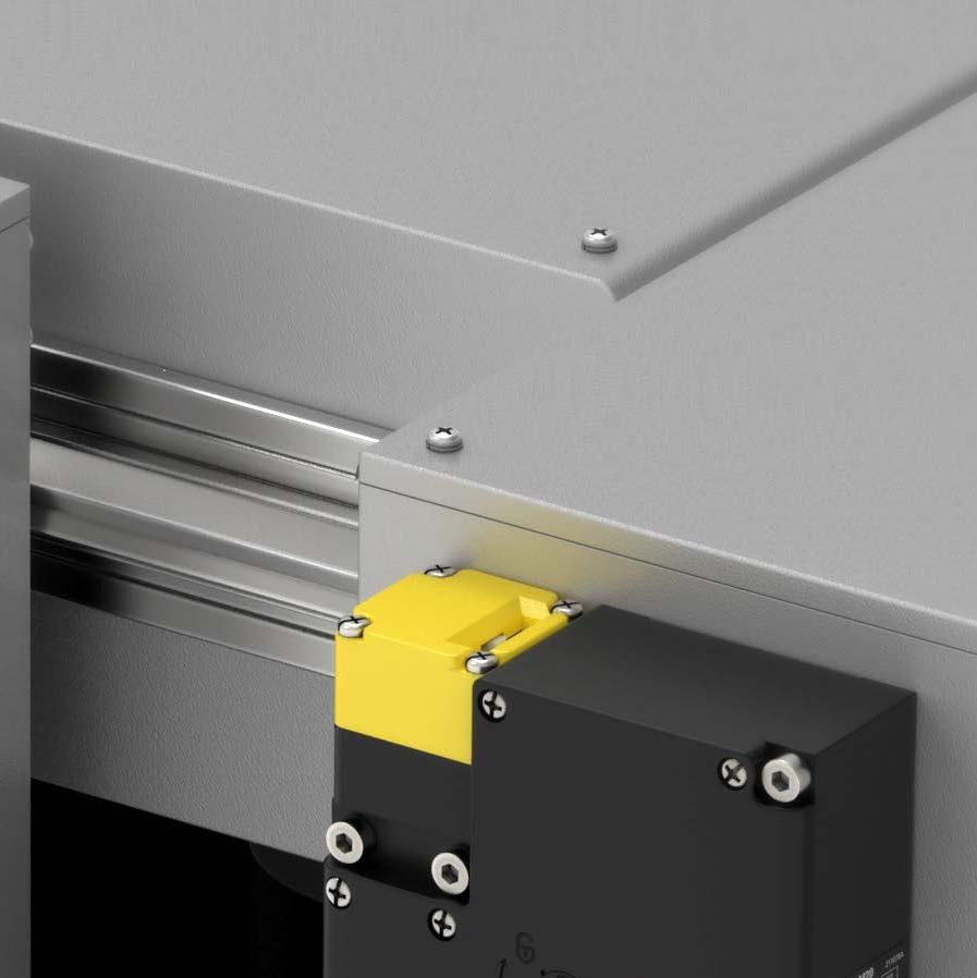
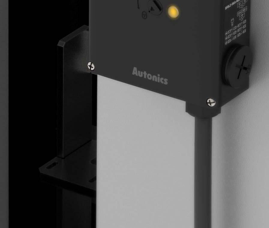

The SFDL2 series flat type door lock switches are available in various models and operation key types for flexible installation.
The SFDL2 series offers diverse installation methods for flexible installation with operation key types. The head can be rotated to change the insert direction of operation keys.
The switches are available in front / rear installation models depending installation requirements. Release button models are also available, allowing operators to unlock the unit manually while inside the operating area.
6 Operation Key Types

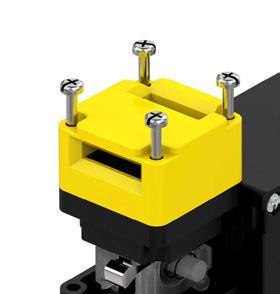


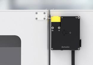
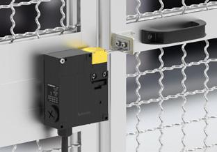
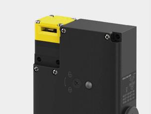


Release keys can be used to unlock the device during power outages or emergency. Standard cross type and special type release keys are available.
※ This function can not be used to stop machine operation.
Two types of lock/release methods are available (Mechanical lock & solenoid release / solenoid lock & mechanical release). The mechanical lock remains locked when the operation key is inserted and unlocks with solenoid power. The solenoid lock remains locked with solenoid power and unlocks when solenoid power is cut off.
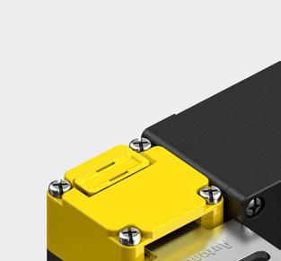
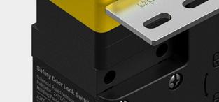
5. Powerful Lock Strength
Powerful lock strength of 1,300 N ensures that the unit will remain locked under most conditions.
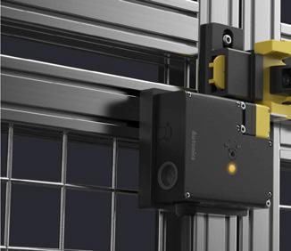
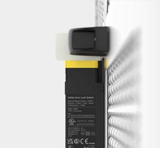
6. Slim and Compact Size
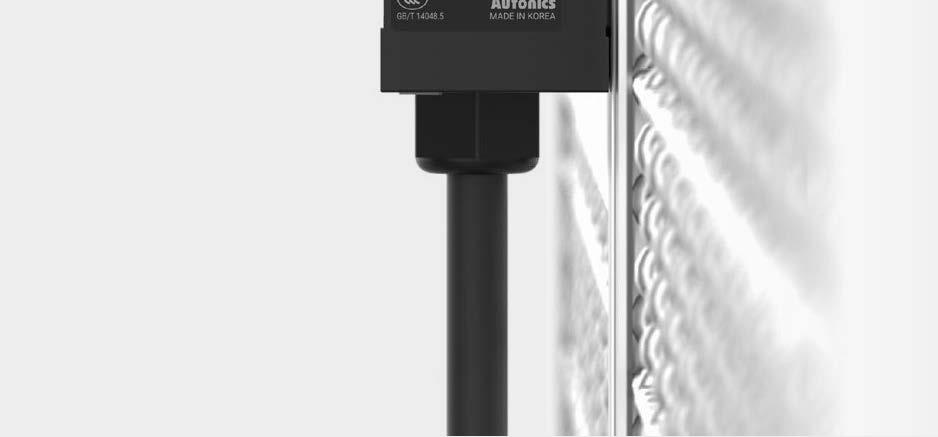
The door lock switches are slim and compact in size (W90 X H105 X D30 mm), allowing installation in tight or limited spaces.
※ Rear Installation
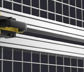
The slide unit (SFDL2-SD) is an accessory to prevent being locked when entering the fence using safety flat type door lock switches.
6-contact switches are built-in, with 4 types of contact configurations for easier application in any environment.
※ Sold separately :
* Group lock device, connecting cable
* Group lock device is an accessory for safety door and door lock switches, to prevent actuator operation from unauthorized access by physically blocking switch insertion area.
※ Connection diagram represents the locked status with the operation key inserted. ( :

Side type (SFD-LT)

Upper type (SFD-LT2)
This is only for reference. For selecting the specific model, follow the Autonics web site.
Unit: mm, For the detailed dimensions of the product, follow the Autonics web site.
❶ Head material
No mark: Metallic
P: Plastic
❸ Contact composition
6A: Lock 2 N.C./
1 N.O. + Door 2 N.C./
1 N.O.
6B: Lock 3 N.C. + Door 2
N.C./1 N.O.
6C: Lock 2 N.C./
1 N.O. + Door 3 N.C.
6D: Lock 3 N.C. + Door 3 N.C.
❺ Connection outlet
specification
M20: M20 thread
G1/2: G1/2 thread
❼ Rear release button
No-mark: None
B: Exist
※ Sold Separately
• Operation key: SFD-K
❷ Lock/Release method
M: Mechanical Lock/Solenoid Release
S: Solenoid Lock/Mechanical Release
❹ Installation direction
No-mark: Front installation B: Rear installation
❻ Release key type
No-mark: Cross type K: Special type
❽ Release key position
No-mark: Front T: Bottom
• Rear release extension button (SFDL2-RE )
• Safety door lock slide unit: SFDL2-SD
• Group locking device: SFD-LT / Connecting cable: SFD-LT-C
■ Rear installawtion
Panel cut-out
Model SFDL2-SFDL2- K-
Directing opening force ≥ 80 N
Directing opening distance ≥ 10 mm
Locking pullout strength ≥ 1,300 N
Operating speed 0.05 to 1 m/s
Operating frequency ≤ 20/min
Mechanical life cycle ≥ 1,000,000 operations (20/min)
Indicator
Vibration (malfunction)
SFDL2- BSFDL2- KB-
Solenoid status or contact status (orange, depending on connection) -
0.35mm amplitude at frequency of 10 to 55 Hz in each X, Y, Z direction for 10 min
Shock 1,000 m/s2 (≈ 100 G) in each X, Y, Z direction for 3 times
Shock (malfunction) 80 m/s2 (≈ 8 G) in each X, Y, Z direction for 3 times
Ambient temperature -10 to 55 , storage: -25 to 65 (a non freezing or condensation environment)
Ambient humidity 35 to 85 %RH , storage: 35 to 85 %RH (a non freezing or condensation environment)
Protection structure IP67 01) (IEC standard, except for head)
Material Head: zinc or PA, case: PA
Approval
Accessory SFDL2- K/KB- (Special type release key): rotating key
Unit weight (packaged)
Normal type: ≈ 400 g (≈ 490 g), rear release button type:≈ 395 g (≈ 485 g)
01) Rated protection structure is for the switch body. Be cautious about preventing the head part from entering the foreign materials such as dust and water.
Contact block
Rated voltage/ current for load
Impulse dielectric strength
Resistive load: 6 A/250 VAC , 0.6 A/250 VDC
Inductive load (IEC): AC-15 3 A/240 VAC DC-13 0.27 A/250 VDC
Inductive load (UL): A300, Q300
Between the terminals of same polarity: 2.5 kV
Between the terminals of different polarity: 4 kV
Between each terminal and non-live part: 6 kV
Insulation resistance ≥ 100 MΩ (500 VDC megger)
Contact resistance ≤ 100 mΩ
Electrical life cycle ≥ 100,000 operations (250 VAC /6 A)
Conditional short-circuit current 100 A
Solenoid
Rated voltage 24 VDC , class 2
Current consumption Supplying power: 0.26A
Normal: max. 0.2A (approx. 3 seconds after supplying power)
Insulation class Class E
Indicator LED
Rated voltage 24 VDC
Current consumption 2.2 mA
The SFN series safety non-contact door switches utilize magnetic type detection to monitor opening and closing of doors. The dedicated controller allows multiple connection of up to 30 units. The switches can be installed vertically or horizontally, and can also be installed from both sides which allow application in various types of doors.


Safety Standards
IEC/EN 60947-5-3
IEC/EN 61000-6-2/4 EN ISO 14119
Certifications


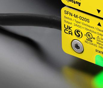


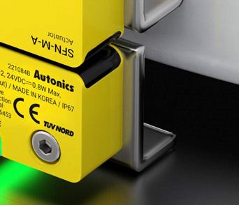


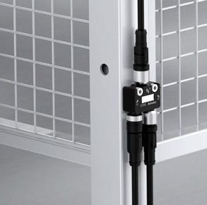


Up to 30 SFN series units can be connected to a single dedicated controller, and various connection types and connectors are available for easy expansion.

1. Connect Up to 30 Units
Connect up to 30 units to a single dedicated controller to save cost and installation time.
2. Two Connection Types
Users can select between cable type and cable connector type models depending on user requirements.


Max. 30 EA
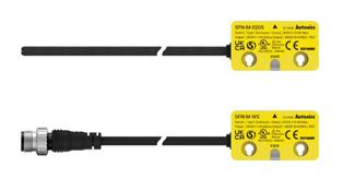
3. Various Connectors
The cable connector type models can be connected to various connectors and extension cables for flexible installation and maintenance.


The units can be installed in right/left, front/rear, and top/bottom directions, allowing flexible installation in various door types.

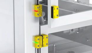
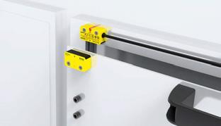
The U-shaped operation indicator allows users to identify operation status from various directions.

IP67 protection structure allows stable and error-free operation even in wet or dusty environments.

Ordering Information
This is only for reference. For selecting the specific model, follow the Autonics web site.
Dimensions
Unit: mm, For the detailed dimensions of the product, follow the Autonics web site.
❶ Sensing type
M: Magnetic type
❷ Cable
020: Cable type (2 m)
050: Cable type (5 m)
W: cable connector type
※ Sold Separately
• Safety controller non-contact door switch unit: SFC-N322
• M12 Connector cable: C1D5- , CID5- , CID5- P
• Branch connector: CCD5-SFN, CYD5-SFN
• Loop connector: CND5-SFN
Ø5, 2m
Ø5, 5m
Model SFN-M-□
Operating distance OFF→ON 5 mm ON→OFF 15 mm
Approval
Unit weight (packaged)
01) It is rated at 23 of ambient temperature, and it may be differed up to ± 20 % by ambient temperature.
Power supply 24 VDC (± 10 %)
Operating frequency 100 Hz
Power consumption 01) ≤ 0.8 W
Auxiliary output PNP open collector output - 24 VDC 10 mA
Operation indicator ON: green, OFF: red
Life expectancy ≥ 20,000,000 times (with low load)
Insulation resistance ≥ 50 MΩ (500 VDC megger)
Protection circuit Surge protection circuit, output short over current protection circuit, reverse polarity protection circuit
Dielectric strength 1,500 VAC 50/60Hz for 1 minute
Vibration 1.0 mm amplitude at frequency of 10 to 55 Hz in each X, Y, Z direction for 2 hours
Vibration (malfunction) 1.0 mm amplitude at frequency of 10 to 55 Hz in each X, Y, Z direction for 10 minutes
Shock 300 m/s2 (≈ 30 G) in each X, Y, Z direction for 3 times
Shock (malfunction) 300m/s2 (≈ 30G) in each X, Y, Z direction in output ON/OFF status for 3 times
Ambient temperature -10 to 55 , storage : -20 to 60 (no freezing or condensation)
Ambient humidity 35 to 85 %RH, storage : 35 to 85 %RH (no freezing or condensation)
Protection structure IP67 (IEC standard)
Connection Cable type / cable connector type model
Cable Ø 5 mm, 5-wire, cable type: 2 m / 5 m, cable connector type: 0.3 m
Wire AWG26 (0.08 mm), 28-core, core diameter: Ø 0.74 mm
Connector spec. M12 plug connector
Material Body/CAP: PC
01) Power to the load is not included.
Characteristic level / Safety category (with SFC-N322) IEC 61508 SIL 3, IEC 62061 SIL
3, ISO 13849-1 PLe Cat.4 - HFT = 1, - Diagnostic Coverage : 99 % (high), - MTTFd = 100 year (high) - Mission time = 20 year, - PFH = 3.88E-09
※ Safety status in case of error: the switch does not have an internal error recognition function, so it can not maintain a safety status in the event of error. Error recognition is processed in the connected controller (SFC-N322).
■ Cable type
■ Cable connector type
• Connection example of branch connector cross type (CCD5-SFN)
• Connection example of branch connector Y type (CYD5-SFN)


The SF2ER series emergency stop button switches are used to stop operation of machines during emergency situations and prevent injuries or hazards. The switches are push-lock / turnreset methods and are available in various head sizes.
Safety Standards
IEC/EN 60947-5-1/5
EN ISO 13850
GB/T 14048.5
Certifications


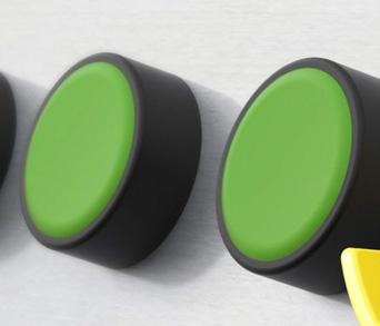


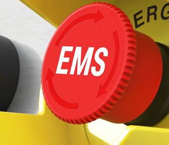


Users can select various head sizes for diverse application settings.
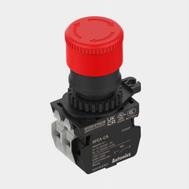
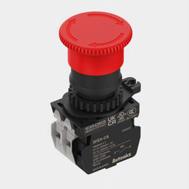
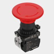
Button head markings are available so that users can select whether to stop operation entirely or partially depending on the situation.
- EMS (Emergency Machine Stop) = stop power supply of dangerous operations
- EMO (Emergency Machine Off) = stop main power supply
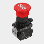
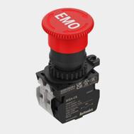

Various accessories are available, including guard rings, nameplates, and radial support.


GUARD-SF2ER(W)GUARD2-SF2ER(W)
This guard ring is sold only as protection guard ring + name plate set. * single metal latch sold separately: GUARD3-SF2ER-L
GUARD2-SF2ER-MGUARD4-SF2ERGUARD41-SF2ERGUARD42-SF2ER
90, STOP Ø 90, OFF Ø 60, STOP Ø 60, OFF


This is only for reference. For selecting the specific model, follow the Autonics web site.
Dimensions
Unit: mm, For the detailed dimensions of the product,
the Autonics web site.
D30 (short head, non-illuminated)
D40 (short head, non-illuminated)
❶ Operation
E: Push-lock, turn-reset
❷ Button
1: D30 (short head, non-illuminated)
2: D40 (short head, non-illuminated)
3: D60 (short head, non-illuminated)
❸ Color
R: Red
❹ Contact block
B: B contact: 1
AB: A contact: 1, B contact: 1
2B: B contact: 2
A2B: A contact: 1, B contact: 2
3B: B contact: 3
❺ Mark
No-mark: No-mark
A: EMO
S: EMS
※ Sold Separately
• Protection guard ring
• Name plate
• Contact block
• Protection guard ring + Name plate set
• Radial support rubber packing / Radial support
• Switch nut fixing handle
D60 (short head, non-illuminated)
For anti-rotation
Standard type Ø 60, STOP GUARD-SF2ER-S Ø 60, OFF GUARD-SF2ER-A
Standard type white Ø 60, STOP GUARD-SF2ER-S-W
Circle type Ø 60, STOP GUARD2-SF2ER-S Ø 60, OFF GUARD2-SF2ER-A
Circle type white Ø 60, STOP GUARD2-SF2ER-S-W
Lock type Ø 60, STOP GUARD3-SF2ER-S Ø 60, OFF GUARD3-SF2ER-A
Metal type
Ø 60, STOP GUARD2-SF2ER-S-M
Ø 60, OFF GUARD2-SF2ER-A-M
Model SF2ER-□□□□-□
Rated voltage/current IEC: AC-15 (220 VAC , 3 A), DC-13 (220 VDC , 0.2 A) UL: A300, Q300
Contact operating power 30 to 40 N/ 1 contact
Operation distance 4.7 mm ± 0.5
Contact operating angle CW (clock wise) 33 to 37º
Rotation torque 0.04 to 0.05 N m
Allowable operation frequency Mechanical: 20 times/minute, electrical: 20 times/ minute
Life cycle Mechanical: ≥ 250,000 times, electrical: ≥ 100,000 times
Applicable wire AWG 18 (0.823 mm2)
Insulation resistance ≥ 100 MΩ (500 VDC megger)
Dielectric strength 2,500 VAC 50/60 Hz for 1 minute
Vibration 1.5 mm double amplitude at frequency of 10 to 55 Hz in each X, Y, Z direction for 2 hours
Vibration (malfunction) 1.5 mm double amplitude at frequency of 10 to 55 Hz in each X, Y, Z direction for 10 minutes
• IEC (EN60947-5-1)
Rated
Shock 1,000 m/s2 (≈ 100 g) in each X, Y, Z direction for 3 times
Shock (malfunction) 250 m/s2 (≈ 25 g) in each X, Y, Z direction for 3 times
Ambient temperature -20 to 65 , storage : -40 to 70 (at no freezing or condensation)
Ambient humidity 35 to 85 %RH , storage : 35 to 85 %RH (at no freezing or condensation)
Protection structure IP65 (oil resistant, IEC standards)
Material Button: PC, body: PA6, lever in fixing unit: PA6
Approval
Weight 69.3 g
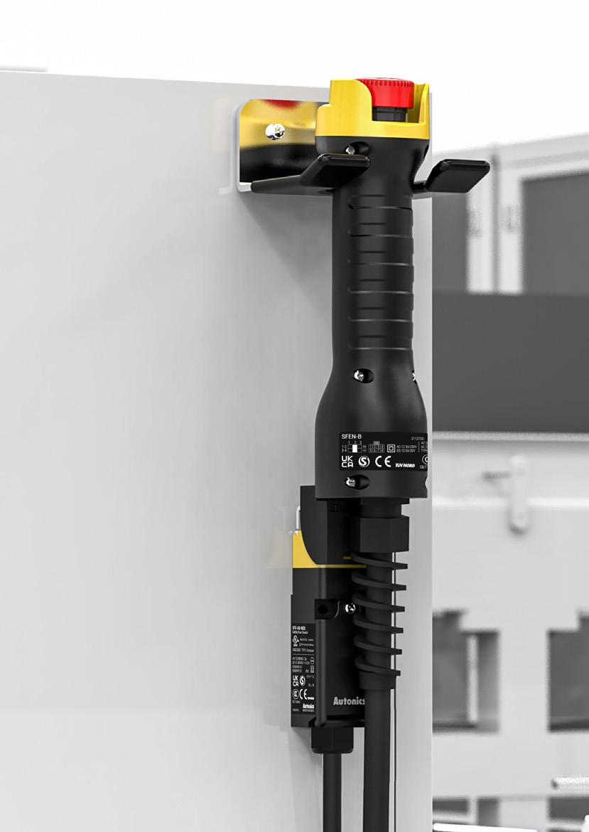

The SFEN series safety grip type enabling switches can be used to manually control operation within a hazardous area during maintenance in order to prevent personal injury in the event of unexpected machine operation. The switches feature high operation sensitivity and various lineup models for diverse applications.
Safety Standards
IEC/EN 60947-5-1
IEC/EN 60947-5-8
GB/T 14048.5
Certifications
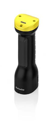
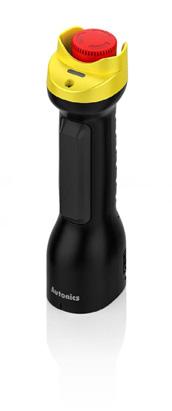
Enabling switches are available in various models including standard, ø16 stop button and momentary button types for diverse user applications.

Standard Type
SFEN Series
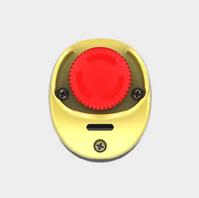
Stop button type
SFEN-B Series
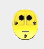
Momentary button type
Series
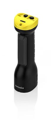
Enabling switches offer high operation sensitivity with 3-position snap action and the ergonomic design allows easy single-hand operation.

Position 1 (OFF)
Position 2 (ON)
Pressed to the middle
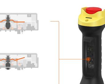

Position 3 (OFF)
Pressed to the end

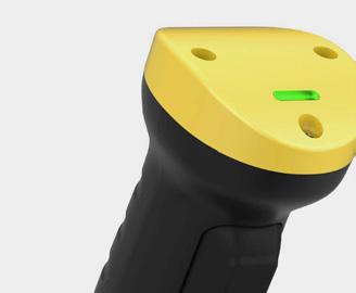
The operation indicator (green LED) allows users to easily identify operation status.



Ordering Information
This is only for reference. For selecting the specific model, follow the Autonics web site.
Unit: mm, For the detailed dimensions of the product, follow the Autonics web site.
❶ Type
No mark: Standard type B: Stop button typeM: Momentary button type
※ Sold Separately
• Mounting bracket: BK-SFEN
• Holding key: SFEN-HK
•Enable switch
Rated Insulation Voltage 250 VAC
Rated through current 2.5 A
Rated inductive load AC-15 (0.75 A / 240 VAC ), DC-13 (0.55 A / 125 VDC )
Rated resistive load 01) 0.75 A / 240 VAC , 0.55 A / 125 VDC
Controller strength 02) Operation direction: 200 N, for 1 min
Operating frequency Electrical: ≤ 20 / min, Mechanical: ≤ 20 / min
Dielectric strength
Between terminals of same polarity, between terminals of different polarity, between terminal and non-live part : 2,500 VAC 50 / 60 Hz for 1 min (impulse dielectric strength)
Electrical life cycle ≥ 100,000 operations (rated load)
Mechanical life cycle OFF ON OFF: ≥ 100,000 operations / OFF ON: ≥ 1,000,000 operations
01) Use a 10 A fuse gl or gG conforming to IEC60269 as short-circuit protection. The body does not have a built-in fuse.
02) Do not use the switch more than the controller strength. Failure to follow this instruction may result in product damage.
•Stop button
Rated Insulation Voltage 250 VAC
Rated through current 3 A
Rated resistive load 01) AC-12 (3 A / 250 VAC ), DC-12 (3 A / 30 VDC )
Controller strength 02) Operation direction: 400 N, for 1 min (operation direction: 0.5 N m, for 1 min)
Operating frequency Electrical: ≤ 10 / min, Mechanical: ≤ 10 / min
Dielectric strength
Between terminals of same polarity: 1,000 VAC 50 / 60 Hz for 1 min. between terminals of different polarity, between terminal and non-live part : 2,000 VAC 50 / 60 Hz for 1 min.
Electrical life cycle ≥ 100,000 operations (rated load) (Push / Release 1 time)
Mechanical life cycle ≥ 100,000 operations (Push / Release 1 time)
01) Use a 10 A fuse gl or gG conforming to IEC60269 as short-circuit protection. The body does not have a built-in fuse.
02) Do not use the switch more than the controller strength. Failure to follow this instruction may result in product damage.
• Momentary button
Rated Insulation Voltage 125 VAC
Rated through current 0.1 A
Rated resistive load 01) AC-12 (0.1 A / 125 VAC ), DC-12 (0.1 A / 30 VDC )
Controller strength 02) Operation direction: 10 N, for 1 min
Operating frequency Electrical: ≤ 25 / min, Mechanical: ≤ 60 / min
Dielectric strength
Between terminals of same polarity: 600 VAC 50 / 60 Hz for 1 min. between terminals of different polarity, between terminal and non-live part : 1,000 VAC 50 / 60 Hz for 1 min.
Electrical life cycle ≥ 100,000 operations (rated load)
Mechanical life cycle ≥ 1,000,000 operations
01) Use a 10 A fuse gl or gG conforming to IEC60269 as short-circuit protection. The body does not have a built-in fuse.
02) Do not use the switch more than the controller strength. Failure to follow this instruction may result in product damage.
Conditional short circuit curre nt 100 A
Min. applied load DC24 V 4 mA
Directing opening force 30 N ± 10
Directing opening distance 4.8 mm ± 0.5
Insulation resistance ≥ 100 MΩ (500 VDC megger)
Vibration (malfunction) 1.5 mm double amplitude at frequency of 10 to 55 Hz in each X, Y, Z direction for 10 min
Shock (malfunction) 150 m/s² (≈ 15 G) in each X, Y, Z direction for 3 times
Ambient temperature -10 to 55 , storage: -25 to 65 (no freezing or condensation)
Ambient humidity 35 to 85 %RH, storage: 35 to 85 %RH (no freezing or condensation)
Insulation class Class ll (double insulation)
Indicator Enable operation indicator (green)
Protection structure SFEN: IP66 (IEC standard) SFEN-B, SFEN-M: IP65 (IEC standard)
Applicable wire AWG 20 to 18 (0.5 to 0.75 mm2)
Connection type M20 connector cable grand
Material Cover: PA66, button: PC, rubber grip: Silicone
International standards IEC 60947-5-1, IEC 60947-5-8, UL 60947-5-1
Approval
Unit weight (package)
SFEN: ≈ 238 g (≈ 363 g)
SFEN-B: ≈ 268 g (≈ 388 g)
SFEN-M: ≈ 252 g (≈ 376 g)
SFEN SFEN-B
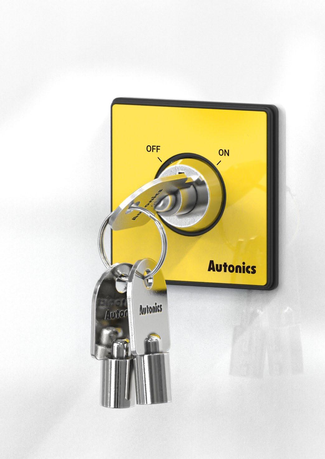

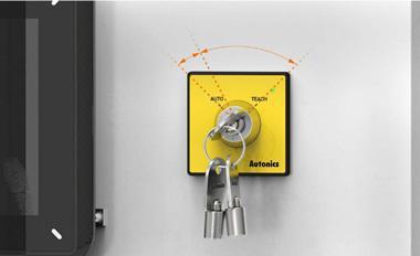
The SF2KR series safety key selector switches are installed in safety fences or industrial equipment doors to control operation of machines, offering additional safety during maintenance in potentially dangerous environments.
Safety Standards
IEC/EN 60947-5-1
GB/T 14048.5
Certifications
The same key can be used with other key selector switches within or outside the fence, offering additional safety. Operators can enter potentially dangerous areas while possessing the key, preventing key loss or entrapment within the hazardous area.
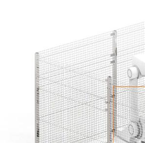
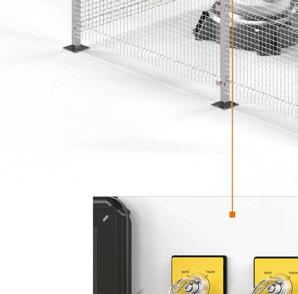
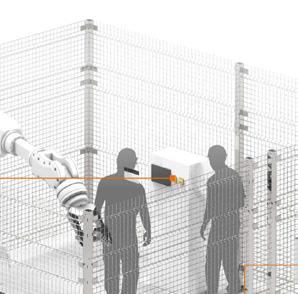
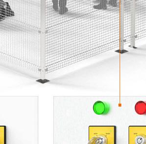


※ Inside the fence (SF2KR- ) Outside the fence (SF2KR-M )
The switches are available in various models including 4 types of key release direction, 3 types of N.C. contact powered location, and 10 types of keys depending on the general/lockable models for diverse applications.
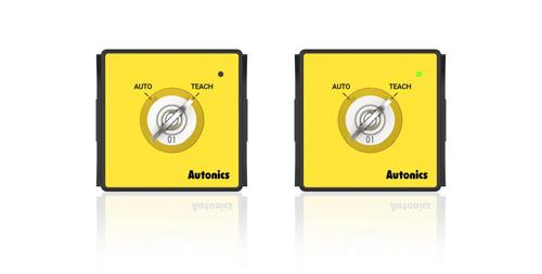
Key selector switches are available in single direction and bi-directional lock types with mechanical/ solenoid release methods, preventing unintended mode switching during maintenance.

Front operation indicator (green LED) allows users to easily identify solenoid operation status.
※ Lock type models only: SF2KR-M
Ordering
This is only for reference. For selecting the specific model, follow the Autonics web site.
Unit: mm, For the detailed dimensions of the product, follow the Autonics web site.
❶ Key lock function
No mark: General type
M: Lockable type
❷ Operation direction
type
❸ Contact block
A2B: N.O. 1 + N.C. 2
3B: N.C. 3
2A2B: N.O. 2 + N.C. 2
※ Sold Separately
• Name plate: SF2KR- -NP□
• Contact block: SFEA-C□
Solenoid input voltage - Non-polar 24 VDC (± 10%)
Solenoid
Conditional short circuit current 100 A
Indicator -
Applicable wire Contact: AWG 18 (0.823 mm2)
Allowable operation frequency 01) 30 times/minute
Life cycle Mechanical: ≥ 100,000 times, electrical: ≥ 100,000 times
Key pushing force ≥ 20 N
Key rotating torque 0.2 to 1.8 N·m
Insulation resistance ≥ 100 MΩ (500 VDC megger)
Dielectric strength 2,500 VAC 50/60 Hz for 1 minute
Solenoid operation (green)
Solenoid power: AWG 24 - 18 Contact: AWG 18 (0.823 mm2)
Vibration 1.5 mm double amplitude at frequency of 10 to 55 Hz in each X, Y, Z direction for 2 hours
Vibration (malfunction) 1.5 mm double amplitude at frequency of 10 to 55 Hz in each X, Y, Z direction for 10 minutes
Shock 300 m/s2 (≈ 30 g) in each X, Y, Z direction for 3 times
Shock (malfunction) 150 m/s2 (≈ 15 g) in each X, Y, Z direction for 3 times
Ambient temperature -20 to 70 02), storage: -40 to 70 (at no freezing or condensation)
Ambient humidity 35 to 85%RH , storage: 35 to 85%RH (at no freezing or condensation)
Protection structure IP65 (front panel, IEC standard)
Material PC, POM
Approval
Unit weight (packaged)
-10 to 55 02), storage: -20 to 70 (at no freezing or condensation)
03) ≈ 130 g (≈ 192 g) ≈ 152 g (≈ 213 g)
01) Rotating and retuning once is counted as one operation.
02) UL approved ambient temperature: 55
03) It is switch with contact blocks.
IEC (EN60947-5-1)
• UL / CSA (UL508, CSA C22.2 No. 14) A300
(A)
Rated


The SFC series safety controllers are used together with safety input devices (switches, sensors, etc.) to provide safe working environments. The controllers feature self-diagnosis function and safety integrity to meet international safety standards.
Safety Standards
IEC/EN 61508 (SIL 3)
IEC/EN 62061 (SIL CL 3)
ISO 13849-1/2 (Cat. 4, PL e)
IEC/EN 60947-5-1 (SRC-R)
IEC/EN 61000-6-2/4 (SFC, SFC-A/N)
EN 50178
Certifications
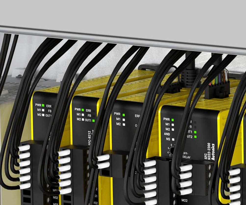
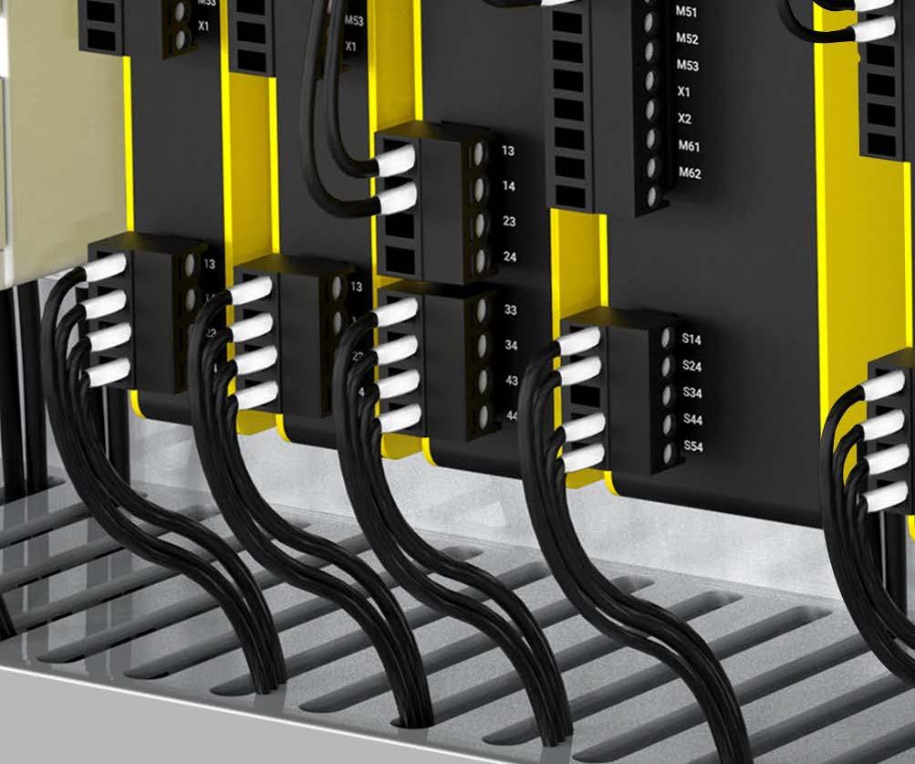
The SFC series features various user-friendly features including slim size, operation indicators, front facing terminals, multiple logic inputs and more.
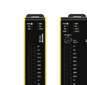
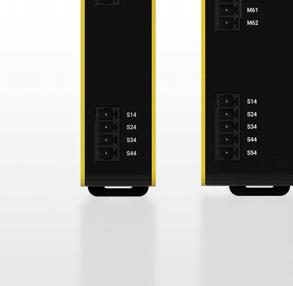

SFC-ER412-
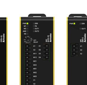
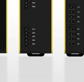

SFC-R212-

The slim space-saving design (minimum width 17.5 mm) allows flexible installation in tight or limited spaces.

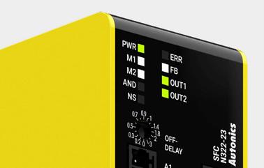


Users can easily check various operation and connection status with the operation indicators.
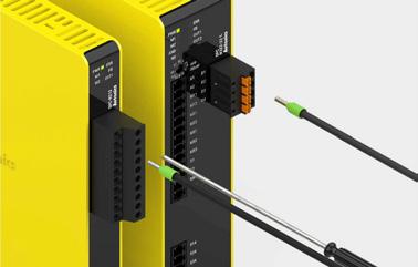
Socket type terminal is located on the front for easy wiring and maintenance.
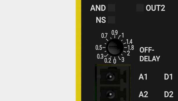
The OFF-delay output models allow up to 16 different OFF-delay time settings.
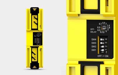


5. Flexible OFF-Delay
On high performance units (SFC-A) and non-contact door switch units (SFC-N), users can set to 1 instantaneous output and 4 OFF-delay outputs using the DIP switch (default: 3 instantaneous, 2 OFF-delay). Auxiliary output is also available to check various error status.
※ 4 safety outputs are available on standard unit controllers.
The expansion relay units (SFCER) can be connected to high performance units (SFC-A) and noncontact door switch units (SFC-N) to increase the number of relay type safety output. (Connect up to 5 expansion relay units per 1 controller)
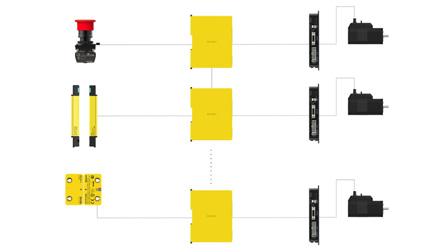
The SFC series can be expanded up to 20 units using logic input offering wider control of safety devices. Safer operation is possible with multiple logic connections.
The SFC series utilizes force guided contact relays to protect from contact welding and ventilation holes are present to reduce heating.
TUV SIL certified force guided contact relays are used to detect failures including contact welding and circuit damage.

Ventilation holes are located on the top and bottom of the product to reduce heating.
Ordering Information
This is only for reference. For selecting the specific model, follow the Autonics web site.
Dimensions
Unit: mm, For the detailed dimensions of the product, follow the Autonics web site. The below is based on SFC-A (screw type) model.
❶ Function
No-mark: Basic unit
A: Advanced unit
N: Non-contact door switch unit (for Autonics SFN Series)
ER: Expansion relay unit
R: Relay unit
❷ No. of safety instantaneous outputs
Number: Number of outputs
❸ No. of auxiliary outputs
Number: Number of outputs
❹ Power supply
2: 24 VDC
❺ Off-delay output elements
No-mark: P channel FET
R: Relay (Relay unit)
❻ No. of Off-delay outputs
No-mark: None
2: 2
❼ Max. Off-delay time
Number: Time (unit: sec)
❽ Terminal type
No-mark: Screw
L: Screwless
Unit
Model SFC-422-□ SFC-A322-2□-□ SFC-N322-2□-□
Power supply 24 VDC
Allowable voltage range 85 to 110% of rated voltage
Power consumption 01) ≤ 2.5 W ≤ 3.0 W ≤ 3.5 W
Input ON: ≥ 11 VDC ≥ 5 mA, OFF: ≤ 5 VDC ≤ 1 mA
Input time ≥ 50 ms, feedback start (manual) : ≥ 100 ms
Cable ≤ 100 m (≤ 100Ω, ≤ 10nF)
Safety output P channel FET 02)
Instantaneous4 X 3 X 03) 3 X 03)
Off-delay 04) - 2 X 03) 2 X 03)
Time accuracy- ≤ ± 5% ≤ ± 5%
Load current Below 2-point output: ≤ DC 1 A Over 3-point output: ≤ DC 0.8 A
Leakage current ≤ 0.1 mA
Operating time (OFF ON) 04) Safety Input : ≤ 50 ms - Logic input: ≤ 200 ms
Non-contact door switch input: ≤ 100 ms
Response (return) time (ON OFF) 05) ≤ 15 ms, non-contact door switch input or logic input: ≤ 20 ms
Auxiliary output 2 × PNP transistor: X1, X2 (error)
Load current ≤ 100 mA
Leakage current ≤ 0.1 mA
Logical AND connections No. of connections: max. 4 units, no. of total connections: max. 20 units No. of layers: max. 5 layers, cable length: ≤ 100 m
SFN connections 06) - - Max. 30 units
Approval
IEC/EN 61508 (SIL3), IEC/EN 62061 (SILCL3)
IEC/EN 60947-5-1, EN ISO 13849-1 (Category 4, PLe)
UL listed E249635
Certification
Unit
01) Not include the power consumption of loads. (SFC-N exclude the power supplied to the non-contact door switch.)
02) Includes a diagnostic pulse (max. 600 ). Be cautious when using the output signal as an input signal for the control device.
03) Available changing via setting switch on the back side of the product.
04) Available to set Off-delay time (max. 3 sec. / 300 sec., depends on model)
05) The operation (response) time of each model. The time increases when a logical connection or expansion relay unit is connected.
06) SFC-N units can only be connected to Autonics non-contact door switch units SFN Series.
Unit Expansion relayRelay
Model SFC-ER412-□ SFC-R412-
Power supply 24 VDC
Allowable voltage range 85 to 110% of rated voltage
Power consumption 01) ≤ 2.5 W≤ 4.0 W≤ 4.0 W≤
Input ON: ≥ 11 VDC ≥ 5mA, OFF: ≤ 5 VDC ≤ 1 mA
Input time ≥ 50 ms, feedback start (manual) : ≥ 100 ms
Cable ≤ 100 m (≤ 100Ω, ≤ 10nF)
Safety output Relay (A contact) Relay (A contact)
Instantaneous4 X 4 X 2 X 2 X
Off-delay 02) - - 2 X
Time accuracy- - ≤ ± 5%
Capacity 240 VAC 5 A resistance load, 30 VDC 5 A resistance load
Life expectancy Mechanical: ≥ 10,000,000 operations, Malfunction: ≥ 50,000 operations
Contact resistance ≤ 100 mΩ
Inductive load switching
IEC60947-5-1: AC15: 230V 3A, DC13: 24V 3A, UL508: B300/R300
Conditional shortcircuit current 100 A 03)
Operating time (OFF ON) 04) ≤ 30 ms 05) ≤ 100 ms
Response (return) time (ON OFF) 04) ≤ 10 ms ≤ 15 ms
Auxiliary output 1 × PNP transistor: X2 (error) 1 × PNP transistor: X1
Load current ≤ 100 mA≤ 100 mA
Leakage current ≤ 0.1 mA
Expansion units connections Max. 5 units-
Approval
IEC/EN 61508 (SIL3), IEC/EN 62061 (SILCL3)
IEC/EN 60947-5-1, EN ISO 13849-1 (Category 4, PLe) UL listed E249635
Certification ᜢ
Unit weight (package)
01) Not include the power consumption of loads.
02) Available to set Off-delay time (max. 3 sec. / 30 sec., depends on model)
03) Use 6A fast-blow fuse under the IEC 60127 standard as a short-circuit protection device.
04) The operation (response) time of each model. The time increases when a logical connection or expansion relay unit is connected.
05) Except operation time of advanced unit, non-contact door switch unit
Pollution 3
Overvoltage category III
Impulse withstand voltag for relay unit (IEC/EN 60947-5-1)
Dielectric strength
Input terminals and relay output terminals: 6 kV
Relay contacts between 13-14 / 23-24 and 33-34 / 43-44 (37-38 / 47-48): 6 kV between 13-14 and 23-24: 4 kV between 33-34 and 43-44 (37-38 and 47-48): 4 kV
[Basic / Advanced / Non-contact door switch unit]
Between all terminals and case: 500 VAC 50/60 Hz for 1 min. [Expansion relay / Relay unit]
Between all terminals and case: 1,500 VAC 50/60 Hz for 1 min.
Between input terminals and output terminals 01): 2,500 VAC 50/60 Hz for 1 min.
Insulation resistance ≥ 100 MΩ (500 VDC megger)
Vibration 02) 0.75 mm amplitude at frequency of 10 to 55 Hz in each X, Y, Z direction for 1 hour
Vibration (malfunc.) 01) 0.5 mm amplitude at frequency of 10 to 55 Hz in each X, Y, Z direction for 10 minutes
Shock 01) 300 m/s2 (≈ 30 G) in each X, Y, Z direction for 3 times
Shock (malfunc.) 01) 100 m/s2 (≈ 10 G) in each X, Y, Z direction for 3 times
Protection structure IP20(IECstandard)
Ambient temperature -10 to 55 , storage: -25 to 65 (rated at no freezing or condensation)
Ambient humidity 25 to 85 %RH, storage: 25 to 85 %RH (rated at no freezing or condensation)
01) In case of relay unit, output terminals between 13-14, 23-24 and 33-34, 43-44 (37-38, 47-48)
02) This data based on the product is mounted with bolts. When installing DIN rail, use the product in an environment with small vibration(condition: less than 0.4 mm double amplitude).
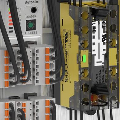
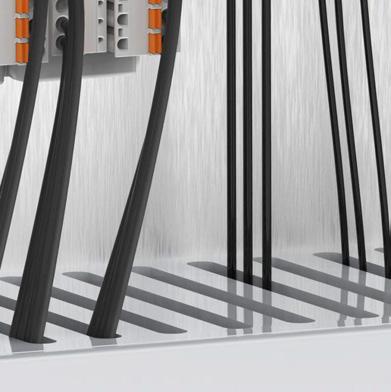

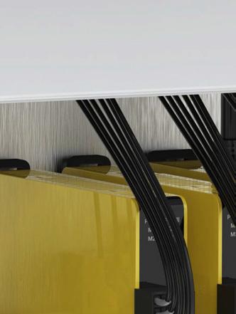
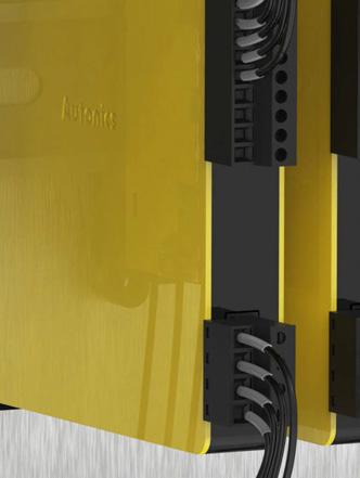
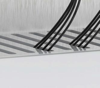

The SFT series safety relay terminal blocks allow safer control system operation with redundant circuits and signal feedback. The relay terminal blocks utilize force guided contacts to prevent contact welding and the compact size allows space-saving installation.
Safety Standards
IEC/EN 61010-1
UL 61010-1
Certifications
Safety relay terminal blocks can be used to control various loads with input signals from safety light curtains and switches. It can also be used for feedback signals to offer safer control systems.
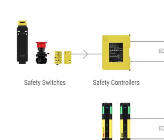


SFT series utilize relays with force guided contacts to prevent contact welding, in accordance with IEC 61810-3.
The status of output contacts can be sent with feedback signals to safety controllers or other devices, allowing safer operation of control systems.

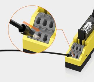
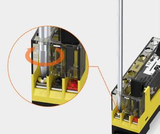
The SFT series is available in screw type and screwless type wiring models. The screwless push-in type connection provides easy wiring, reduced installation time, and even tightening.

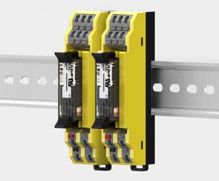
The SFT series supports both DIN rail mount and screw mount methods, for application in diverse environments.

Ordering Information
This is only for reference, the actual product does not support all combinations. For selecting the specified model, follow the Autonics website.
Dimensions
Unit: mm, For the detailed drawings, follow the Autonics website.
❶ Terminal type
S: Screw type
L: Screwless type
❷ Number of pole
4P: 4-pole
6P: 6-pole
❸ Power supply
24V: 24 VDC
❹ Relay Contact
2A2B: 2A2B (4-pole)
3A1B: 3A1B (4-pole)
4A2B: 4A2B (6-pole)
5A1B: 5A1B (6-pole)
3A3B: 3A3B (6-pole)
Model SFTS-4P24VSFTS-6P24VSFTL-4P24VSFTL-6P24V-
No. of pole 4 6 4 6
Applied relay 01) 4-pole - SFS2-DC24V: 2A2B, SFS3-DC24V: 3A1B 6-pole - SFS4-DC24V: 4A2B, SFS5-DC24V: 5A1B, SFS6-DC24V: 3A3B
Power supply 24 VDC ±10 %
Rated load voltage 250 VAC 50/60 Hz, 30 VDC
Continuous current 6 A 02)
Indicator Operation indicator: green
Terminal type Screw Screwless
Applicable wire - solid Ø 0.3 to Ø 1.2 mm Ø 0.6 to 1.25 mm 03)
Applicable wire - stranded AWG 22-16 (0.30 to 1.25 mm²) AWG 22-18 (0.30 to 0.80 mm²) 03) 04)
Crimp terminal connection
tensile strength ≥ 30 N -
Tightening torque 0.5 to 0.6 N m -
Stripped length - 8 to 10 mm
Insulation resistance ≥ 1,000 MΩ (500 VDC megger)
Dielectric strength (coil-contact) 4,000 VAC 50/60 Hz for 1 minute
Dielectric strength (different poles contact)
Dielectric strength (same polarity contact)
Vibration
Vibration (malfunction)
2,500 VAC 50/60 Hz for 1 minute
2,500 VAC 50/60 Hz for 1 minute
0.75 mm amplitude at frequency 10 to 55 Hz in each X, Y, Z direction for 2 hours
0.75 mm amplitude at frequency 10 to 55 Hz in each X, Y, Z direction for 10 minutes
Shock 300 m/s² (≈ 30 G) in each X, Y, Z direction for 3 times
Shock (malfunction) 150 m/s² (≈ 15 G) in each X, Y, Z direction for 3 times
Ambient temperature -25 to 70 , storage: -30 to 80 (no freezing or condensation)
Ambient humidity 25 to 85 % RH, storage: 25 to 85 % RH (no freezing or condensation)
Protection structure IP20 (IEC standard)
Material CASE, BASE, COVER: PC Terminal: C2680 CASE, BASE: PC, Terminal: PA66, Copper, Stainless Steel
Certification ᜢ ᜧ
01) For the detailed specification, refer to the materials from the manufacturer (PANASONIC).
02) Continuous current is the maximum current at each contact and must not exceed the total current depending on the number of contacts.
03) Use the cable of copper conductor in 60 temperature class.
04) When using the stranded wire, use End Sleeve (Ferrule Terminal).
• Safety relays provided by the model are different.
• It is possible to purchase the safety relay separately. For the detailed specification, refer to the materials from the manufacturer (PANASONIC).
Model SFS2DC24V SFS3DC24V SFS4DC24V SFS5DC24V SFS6DC24V
No. of pole 4 6
Contact
arrangement 2A2B3A1B4A2B5A1B3A3B
Applied models SFTS-4P-24VSFTL-4P-24VSFTS-6P-24VSFTL-6P-24V-
■ Screw type: 4-pole
SFS2-DC24V(2a2b)
■ Screw type: 6-pole
SFS4-DC24V(4a2b)
SFS3-DC24V(3a1b)
SFS5-DC24V(5a1b)
■ Screwless type: 4-pole
SFS2-DC24V(2a2b)
■ Screwless type: 6-pole
SFS3-DC24V(3a1b)
SFS4-DC24V(4a2b)
SFS5-DC24V(5a1b)
SAFETY is the safety product brand of Autonics that protects workers from the risk of accidents in industry sites. In the brand design concept, the meaning of this safety protection is visualized using a square as a basic element.
Korea (Headquarters)
39, Magokjungang 5-ro 1-gil, Gangseo-gu, Seoul, Republic of Korea, 07594
T 82-2-2048-1577
E sales@autonics.com
Germany
Autonics Germany Office
T 49-69-242-992-32
E germany@autonics.com
Japan
Autonics Japan Corporation
T 81-3-6435-8380 F 81-3-6435-8381
E ja@autonics.com
Türkiye
Autonics Otomasyon Ticaret Ltd. Sti.
T 90-216-365-9117/3/4 F 90-216-365-9112
E turkiye@autonics.com
Brazil
Autonics do Brasil Comercial Importadora e Exportadora LTDA
T 55-11-2307-8480 / 3195-4610 F 55-11-2309-7784
E comercial@autonics.com.br
India
Autonics Automation India Private Limited
T 91-22-2768-2570
E india@autonics.net.in
Malaysia
Mal-Autonics Sensor Sdn. Bhd.
T 60-3-7805-7190 F 60-3-7805-7193
E malaysia@autonics.com
USA
Autonics USA, Inc.
T 1-847-680-8160 F 1-847-680-8155
E sales@autonicsusa.net
Sensors, Controllers, Motion Devices, Safety, Measuring Equipment, Connection
Photomicro Sensors
Proximity Sensors
China
Autonics Electronic (Jiaxing) Corporation
T 86-573-8216-1900 F 86-573-8216-1917
E china@autonics.net
Indonesia
PT. Autonics Indonesia
T 62-21-8088-8814/5
E indonesia@autonics.co.id
Mexico
Autonics Mexico S.A. DE C.V
T 52-800-523-2131
E ventas05@autonics.com
Vietnam
Cong Ty Tnhh Autonics Vina
T 84-28-3771-2662 F 84-28-3771-2663
E vietnam@autonics.com