


Temperature control is essential in many aspects of the industry, such as maintaining product quality, improving process efficiency, and saving energy, and it increases productivity and reliability across the industry.
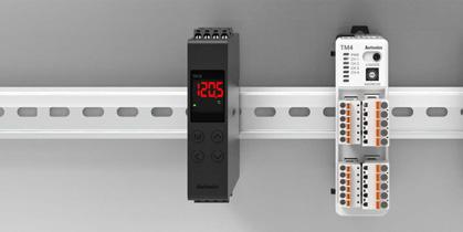
There are temperature controllers, temperature sensors, and actuators which are organically connected to detect temperature changes and control them to maintain the desired temperature. The temperature sensors convert the temperature of the control target into an electrical signal and transmit it to the temperature controller, thereby monitoring real-time temperature changes. The temperature controllers compare the target temperature and the current temperature based on the signal received from the temperature sensors, analyze the difference, and send control signals to the actuators. The actuators actually control the temperature according to this signal, and maintain the temperature constant through various equipment such as heaters, coolers, electronic switches, and solenoid valves.


Autonics provides optimal temperature control solutions tailored to various industrial environments to achieve customer satisfaction. Based on our rich field experience and advanced technological prowess, we will continue to strengthen our differentiated competitiveness in the temperature control field by providing stable and reliable products.


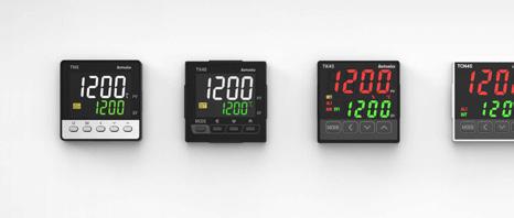
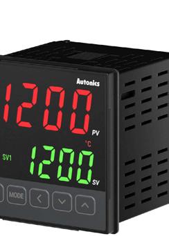
Temperature controllers are devices that convert temperature changes into electrical signals, connect to analog outputs of temperature sensors or various converters, and display and control the temperature or analog changes. Autonics provides various types of temperature controllers by types and purposes and users can select sizes and mounting methods flexibly to meet the diverse needs in different industrial environments. Autonics provides precise temperature control solutions allowing accurate temperature control with high-precision and high-speed temperature control with various functions.


Digital Type
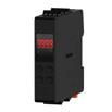
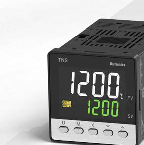
· 2-DOF PID Temperature Controllers | TN Series
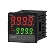
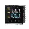
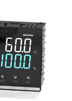
· LCD Display PID Temperature Controllers | TX Series
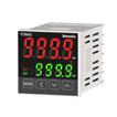
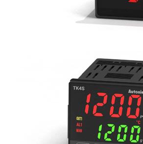
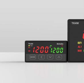
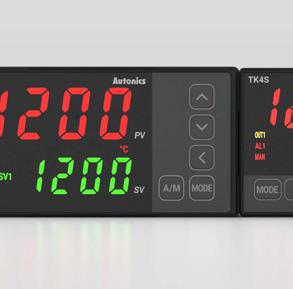
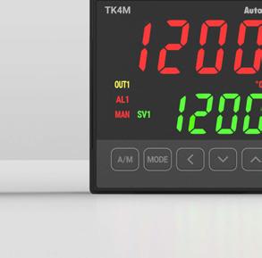
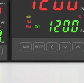
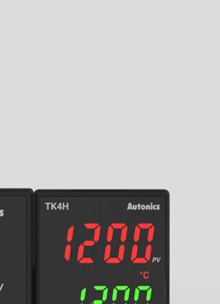
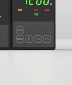
· High Performance PID Temperature Controllers | TK Series
· Economical Dual Display PID Temperature Controllers | TCN Series
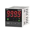
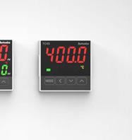
· Economical Single Display PID Temperature Controllers | TC Series


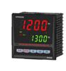
· Bar Graph PID Temperature Controllers | KPN Series
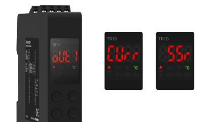
· Slim Single Display PID Temperature Controllers | TR1D Series
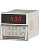
· Thumbwheel Switch Digital Temperature Controllers | T3/T4 Series
· High Performance Refrigeration Temperature Controllers | TF3 Series
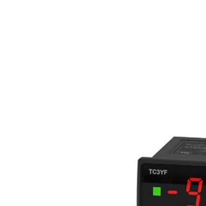
· Refrigeration Temperature Controllers | TC3YF Series
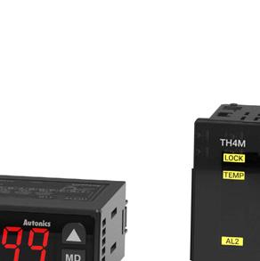
· Temperature/Humidity Temperature Controllers | TH4M Series
Analog Type
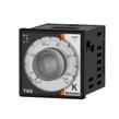
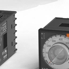
· Analog Non-Indicating Type PID Temperature Controllers | TA Series
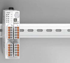
Modular Type
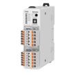
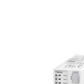
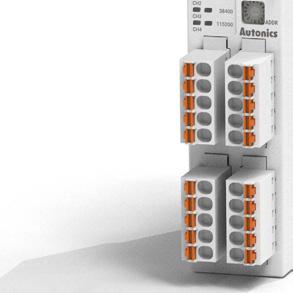
· Modular Multi-Channel High Performance Temperature Controllers | TMH Series
· Modular Multi-Channel PID Temperature Controllers | TM Series


Temperature Indicators
· 1-Channel Digital Indicators | T3/T4 Series
· 1-Channel Digital Indicators | KN-2000W Series
· Bar Graph Indicators | KN-1000B Series


Controllers - Digital

-
Control heating, cooling control simultaneous heating and cooling control heating, cooling control simultaneous heating and cooling control heating, cooling control simultaneous heating and cooling control heating, cooling controlheating, cooling control
Control method ON/OFF, P, PI, PD, PID, 2 DOF PID ON/OFF, P, PI, PD, PIDON/OFF, P, PI, PD, PIDON/OFF, P, PI, PD, PIDON/OFF, P, PI, PD, PID
Size W 48 × H 48 mm W 48 × H 96 mm W 96 × H 96 mm
W 48 × H 48 mm
W 72 × H 72 mm
W 48 × H 96 mm
W 96 × H 96 mm
W 48 × H 24 mm
W 48 × H 48 mm (11-pin plug type)
W 48 × H 48 mm
W 72 × H 72 mm
W 96 × H 48 mm
W 48 × H 96 mm
W 96 × H 96 mm
W 48 × H 48 mm
W 72 × H 72 mm
W 48 × H 96 mm
W 96 × H 96 mm
W 48 × H 48 mm
W 48 × H 48 mm (11-pin plug type)
W 72 × H 36 mm
W 72 × H 72 mm
W 48 × H 96 mm
W 96 × H 48 mm
W 96 × H 96 mm
Display part 11 segment, LCD 11 segment, LCD 7 segment, LED7 segment, LED7 segment, LED
Input channel 1-channel 1-channel 1-channel 1-channel 1-channel
Input
Thermocouple : K. J, E, T, B, R, S, N, C, G, L, U, Platinel II, L(RUS)
RTD : Cu50 Ω, Cu100 Ω, JPt100 Ω, DPt50 Ω, DPt100 Ω, Nickel120 Ω Analog : 0-10V, 0-5V, 1-5V, 0-100mV, 0-20mA, 4-20mA
Thermocouple : K, J, L, T, R, S
RTD : Cu50 Ω, DPt100 Ω
Thermocouple : K. J, E, T, B, R, S, N, C, G, L(IC), U, Platinel II
RTD : Cu50 Ω, Cu100 Ω, JPt100 Ω, DPt50 Ω, DPt100 Ω, Nickel120 Ω Analog : 0-10V, 0-5V, 1-5V, 0-100mV, 0-20mA, 4-20mA
Thermocouple : K, J, L, T, R, S RTD : Cu50 Ω, DPt100 Ω
Thermocouple : K, J, L
RTD : Cu50 Ω, DPt100 Ω
Control
Option input CT, digital
Option output Alarm (250 VAC, 3 A 1a), tranmission, communication
Communication (Modbus RTU)
Alarm (250 VAC, 3 A 1a), tranmission, communication
CT, digital
Alarm(250 VAC, 3 A 1a, 250 VAC, 0.5 A 1a), tranmission, communication
Alarm (250 VAC, 1 A 1a)Alarm (250 VAC, 1 A 1a)
Installation Method panel panel panel, DIN Rail panel panel, DIN Rail
Protection Structure (Front panel)
Certification
IP50 IP65, IP50 (TK4SP)
Temperature Controllers - Digital Type


Power
Control heating, cooling control simultaneous heating and cooling control heating, cooling control simultaneous heating and cooling control
Control method ON/OFF, P, PI, PD, PID ON/OFF, P, PI, PD, PID ON/OFF, PON/OFF
Display part 7 segment, LED control output bar graph 7 segment, LED7 segment, LED7 segment, LED7 segment, LED11 segment, LCD
Input channel 1-channel 1-channel 1-channel 1-channel, 3-channel 1-channel 1-channel
Input Thermocouple : K. J, E, T, B, R, S, N, C, G, L(IC), U, Platinel II RTD : Cu50 Ω, Cu100 Ω, JPt100 Ω, DPt50 Ω, DPt100 Ω, Nickel120 Ω Analog : 0-10V, 0-5V, 1-5V, 0-100mV, 0-20mA, 4-20mA
Thermocouple : K. J, L, T, R, S RTD : Cu50 Ω, DPt100 Ω, Nickel120 Ω
Thermocouple : K, J, R RTD : DPt100 Ω
RTD : DPt100 Ω Thermistor : NTC 5 kΩ, NTC 10 kΩ,
RTD : DPt100 Ω Thermistor : NTC 5 kΩ Temperature/ Humidity Transducers (THD-RM)
Control output Relay SSR Current Relay SSR Current or SSR Relay SSR Current
compressor (COMP) Defrost (DEF) Auxiliary (AUX)
compressor(COMP)
Defrost (DEF)
Evaporator fan (FAN) Relay
Option input CT, Remote SV, digital CT - digital - -
Option output Alarm (250 VAC, 1 A 1a), tranmission, communication
Communication
Installation
Protection Structure (Front panel)
Certification
Alarm (250 VAC, 3 A 1a), tranmission, communication Alarm (250 VAC, 2 A 1a)
CommunicationAlarm (250 VAC, 1 A 1a)
Alarm (250 VAC, 3 A 1a)
ᜣ(Except RTD option models)ᜫ DC : ᜫ
Temperature Controllers - Analog Type
Series TA
Type
Analog Non-Indicating PID
Power voltage 100 - 240 VAC, 50/60 Hz
Sampling cycle 100 ms
Control heating
Control method ON/OFF, PID
Size W 48 × H 48 mm (8-pin plug type)
W 72 × H 72 mm
W 96 × H 96 mm
Display part PV deviation, Error display, LED type
Input channel 1-channel
Input Thermocouple : K, J RTD : DPt100 Ω
Control output Relay SSR
Option input -
Option output -
Communication -
Installation Method Panel, DIN Rail
Protection Structure (Front panel) -
Certification ᜢᜧᜫ
p. 50
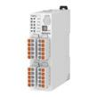
Temperature Controllers - Modular Type
52 p. 56
Series TMH (Control Module)TM
Type
Modular Multi-Channel High Performance PID
Modular Multi-Channel PID
Power voltage 24 VDC 24 VDC
Sampling cycle 50 ms (2-channel or 4-channel) 50 ms (2-channel), 100 ms (4-channel)
Control heating, cooling control simultaneous heating and cooling control heating, cooling control simultaneous heating and cooling control
Control method ON/OFF control, P, PI, PD, PID ON/OFF, P, PI, PD, PID
Size W 30 × H 100 mmW 30 × H100 mm
Display part None- parameter settingNone- parameter setting
Input channel 2-channel, 4-channel2-channel, 4-channel
Input
Thermocouple : K. J, E, T, B, R, S, N, C, G, L(IC), U, Platinel II
RTD : Cu50 Ω, Cu100 Ω, JPt100 Ω, DPt50 Ω, DPt100 Ω, Nickel120 Ω Analog : 0-10V, 0-5V, 1-5V, 0-100mV, 0-20mA, 4-20mA
Thermocouple : K. J, E, T, B, R, S, N, C, G, L(IC), U, Platinel II
RTD : Cu50 Ω, Cu100 Ω, JPt100 Ω, DPt50 Ω, DPt100 Ω, Nickel120 Ω
Control output Relay SSR Current Relay SSR Current
Option input CT, Digital CT, Digital
Option output Alarm (250 VAC, 3A 1a), communication Alarm (250 VAC, 3A 1a), communication
Communication O O
Installation Method DIN Rail DIN Rail
Protection Structure (Front panel)
Certification
Temperature Indicators - Digital Type
Series T3/T4 (Indicator Type)
Type
Power
Sampling cycle
Size
W 48 × H 24 mm
W 72 × H 36 mm
W 96 × H 48 mm
W 48 × H 48 mm (8-pin plug type)
W 72 × H 72 mm
W 48 × H 96 mm
W 96 × H 96 mm
Display part 7 segment, LED
Input
Thermocouple : K, J, R
RTD : DPt100 Ω
7 segment, LED
Thermocouple : K. J, E, T, B, R, S, N, C, L(IC), U, Platinel II
RTD : Cu50 Ω, Cu100 Ω, JPt100 Ω, DPt50 Ω, DPt100 Ω
Analog : 0-20mA, 4-20mA, -50-50mV, -200-200mV, -1-1V, -1-10V
7 segment, LED, bar graph
Thermocouple : K. J, E, T, B, R, S, N, C, L(IC), U, Platinel II
RTD : Cu50 Ω, Cu100 Ω, JPt100 Ω, DPt50 Ω, DPt100 Ω
Analog : 0-20mA, 4-20mA, -50-50mV, -199.9-200mV, -1-1V, -1-10V
Option input - Digital Digital
Option output -
Alarm (250 VAC, 3A 1c, 250 VAC, 1A 1a), tranmission, communication
Alarm (250 VAC, 3A 1c, 250 VAC, 1A 1a), tranmission, communication
Communication - O O
Installation Method panel, DIN Rail panel panel
Certification ᜫ
* The following information may vary by model. For more information, please refer to the specification pages.


Non-Indicating Type
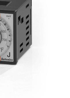


Autonics temperature controllers support various products by type and purpose for the user environment.Autonics provides digital display, analog, and non-indicating models by type. The digital type allows users to check the setting value directly through the display with various functions. The analog type allows users to set the temperature and output with a dial for easy operation. The non-indicating type allows users to easily set and monitor parameters through software. By purpose, Autonics provides general-use models that allow heating, cooling, and heating and cooling control, refrigeration models that allow cooling control, and temperature/ humidity models that allow heating and cooling control. Users can select and use various temperature controllers according to their environment.

[By Purpose]


Autonics provides various sizes of products including standard DIN sizes for different user environments. This allows users to select the size optimized for a specific industrial environment or equipment, thereby increasing installation convenience and space efficiency. Autonics provides customized temperature control solutions that meet various field needs in a wide range of sizes.

Autonics provides panel mounting and DIN Rail mounting by user environment and installation methods. The panel mounting type is mounted on the control panels for intuitive operation and easy confirmation. The DIN Rail mounting type is installed in a limited space efficiently allowing installation in tighter spaces. Through these two mounting methods, users can flexibly select and install the temperature controllers by various industrial environments.

Autonics supports various control methods including 2 DOF PID, PID, P, PI, PD, ON/OFF control. With these various temperature control options, users can implement the optimal control solution for each environment. This allows for accurate temperature maintenance and management.
* Temperature control methods may vary by series, please refer to the specification pages for details.
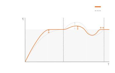
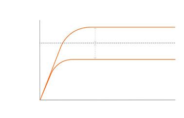
1) 2-DOF PID Control Algorithm
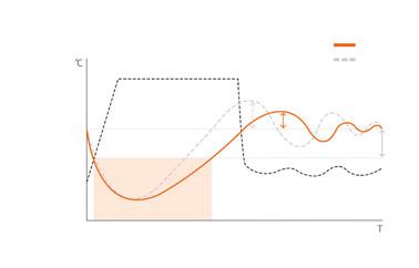
The two-degree-of-freedom (2-DOF) algorithm can accurately reach the set temperature (SV) and respond quickly to disturbances while reducing overshoot for accurate and precise temperature control. This method can effectively control environments with severe load fluctuations or where the set value changes frequently by reducing overshoot when reaching the target value and responding quickly to external disturbances.

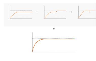
2) PID Control Algorithm
This is a combination of proportional control, integral control, and differential control, and provides excellent control results even for control targets with delay times, enabling ideal temperature control.

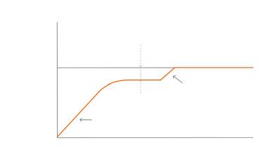
3) P Control Algorithm (Proportional control)
This is a control operation that outputs a manipulation amount proportional to the deviation between the set value and the current value. It has less overshoot and hunting.

4) PI Control Algorithm
(Proportional integral control)
This is a control operation that automatically corrects the offset that occurs in proportional control through integral operation. It removes the offset, and it must be used with proportional control.
Proportional integral control Proportional control

5) PD Control Algorithm
(Proportional differential control)
This is a control operation that stabilizes the control temperature in a short time by giving a large amount of manipulation against sudden disturbances. It responds quickly to disturbances, and it must be used with proportional control.
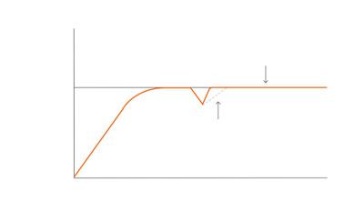
Proportional differential control Proportional control
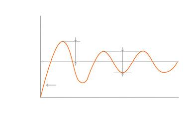
6) ON/OFF Control Algorithm
This is a method of repeating ON/OFF operations based on the set value. Compared to PID control, the response is faster, but the precision is lower.
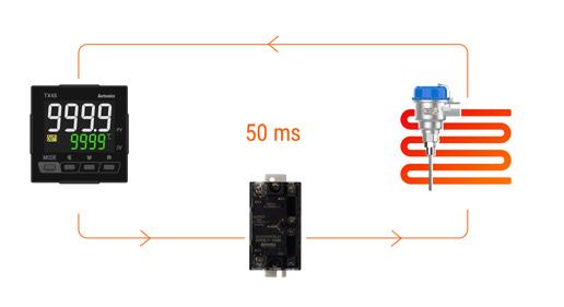
As temperature controllers are devices that convert analog values such as temperature sensors into digital values, the faster the sampling speed, the faster the response speed. Autonics temperature controllers realize high-speed sampling of up to 50 ms, and can be applied to processes that require fast response supporting high-speed and high-precision temperature control.
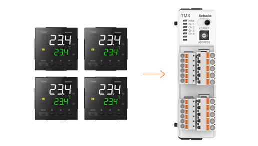
Multi-channel temperature controllers are capable of controlling 2-channels or 4-channels of input and outputs. One 4-channels model can perform the role of 4 temperature controllers. It saves space, increases cost efficiency, and enables various temperature control easily. In addition, modular temperature controllers provide communication modules and option modules. Users can expand or combine control, communication, and option input/output modules in various environments.
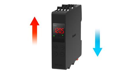
The controllers can simultaneously control heating and cooling elements, providing efficient temperature control. For models that control heating and cooling simultaneously, the heating side performs a control operation in which the output of the controller decreases as the temperature measurement value increases. The cooling side performs a control operation in which the output of the controller increases as the temperature measurement value increases. The temperature controller can be applied to heating control systems or cooling control systems.
8. Various Communication Protocols9. PLC Ladderless Communication
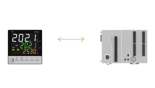
Temperature controllers support various communication protocols including RS485, RS422, and Ethernet. This allows smooth data transmission and system integration and enables efficient monitoring and control connecting with various automation systems.
Working efficiency increases due to initial settings without writing a separate ladder when communicating with the upper PLC via RS485.
Communication Protocols
Autonics provides various funtions for more efficient temperature control. Autonics introduces main functions to increase customer convenience and achieve accurate temperature control. These functions can help users easily implement the temperature management solutions, including precise temperature control, flexible control options, and alarms.
Main functions may vary by series, please refer to the specification pages for details.
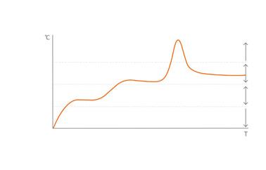
1) Group PID and Zone PID function
When the temperature control range is wide, zones can be separated according to the temperature range and apply different PID values to each zone for detailed control. In the case of a control process with a wide temperature range, since the optimal PID coefficients are different by the temperature range, this function allows users to apply PID data differently to each zone. This function is widely used in industrial ovens, heating systems, plastic heaters, and environmental control (greenhouses, farms, animal farms).
2) Anti-over Integration (ARW) Function
When the control output reaches the maximum point, the range can be set to perform the integral operation to prevent overshoot with ARW function.

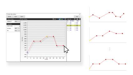
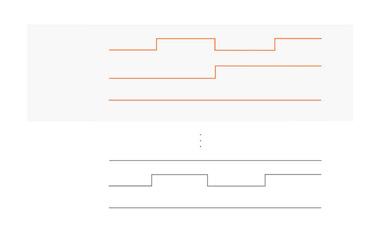
3) Pattern Control (Program Control Models)
Program control models can be used to easily set the control pattern by sequentially setting the target temperature and time of each step. Up to 10 patterns can be registered, and up to 20 steps can be configured for each pattern. Users can easily draw the pattern with DAQMaster software by clicking the coordinates of the timetemperature graphs.
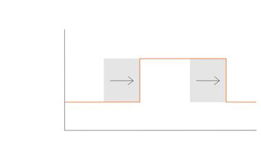
4) Timer Function (Fixed Control Models)
Fixed control models can be used to preset the operation time by delaying the On/Off control outputs or by maintaining the PV for a set amount of time.
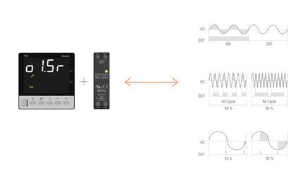
5) SSR Drive Output Control Options (SSRP function)
Users can select from ON/OFF control, cycle control, and phase control using standard SSR drive output option. This enables linear control even with SSR output, allowing for precision control at low cost without a separate power regulator.
Users can select between current output and SSR drive output by parameter configuration. 6) Switch Between Current Output and SSR Drive Output
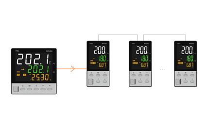
7) Synchronous Control with Sync-Master Communication
The SV and Run/Stop status of the master device can be synchronized with up to 31 devices to simultaneously control multiple zones.
8) Input Compensation and Input Digital Filter
Input compensation function compensates for errors caused by external input devices. Through the input digital filter, the current temperature value can be stabilized when the current temperature value repeatedly fluctuates due to rapid changes in the input signal and is reflected in the manipulated amount.

9) Alarm Function
The alarm output in the thermostat can be set by combining the alarm operation and alarm option.
Alarm operation Deviation high limit alarm, Deviation low limit alarm, Deviation high, low limit alarm, Deviation high, low reverse alarm, Absolute value high limit alarm, Absolute value low limit alarm, Sensor break alarm, Loop break alarm (LBA)
Alarm option Standard alarm, Standby sequence 1, Standby sequence 2, Alarm latch, Alarm latch and standby sequence 1, Alarm latch and standby sequence 2
* The alarm function varies by series, models, and control output.


Users can set up to 10 events such as PV high/low limit, disconnection and control operation notification. Logic operation result can be transmitted with relay alarm output and real-time monitoring is possible via RS485 communication.
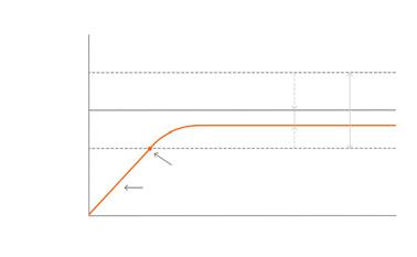
When using proportional control (P/PD), since the rise and fall times of the heater differ depending on the heat capacity of the control target and heater capacity, normal deviation generally occurs even when the control becomes stable. In this case, users can obtain a more accurate value by setting/compensating with manual reset.
Set reset to less than 50.0%
Normal deviation
Normal deviation
Set reset to greater than 50.0%

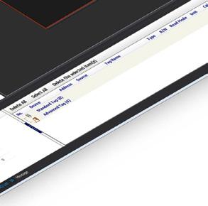
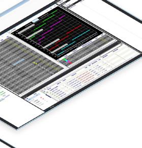
11. Comprehensive Device Management Software DAQMaster
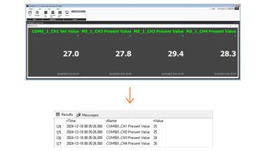
DAQMaster (free provided) is a comprehensive device management software used to configure parameters and monitor real-time data with communication supported devices from Autonics.


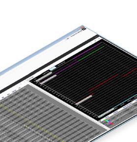


Log files are automatically created and saved as CSV files at user specified times.
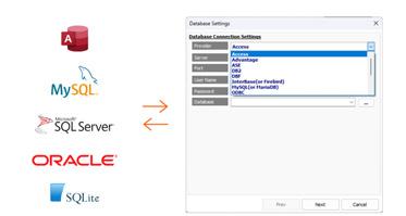
Information can be changed to database using database management systems (Access, MySQL, SQL Server, SQLite) in real-time, allowing easy creation and management of various databases.
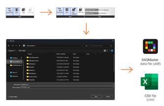
While monitoring data can be logged and saved into DAQMaster data files (*.ddf) or CSV files (*.csv). The saved CSV file can be opened directly onto Excel spreadsheets. Define log data file naming rules destination folders for easier file management.
Temperature Control System
1. Temperature sensor

2.Temperature controller
Temperature value input


3. Controller
Control output

Control

Temperature sensors convert the temperature of the controlled subject into an electrical signal and transmit the signal to the temperature controller.
1) Temperature sensors type and description
• Thermocouple
Principle that a small electromotive force is generated by joining the ends of different metal wires by temperature change of the joint area.
- Advantages : Wide temperature measurement range, Self-signal generation, No self-heating, Robustness
- Disadvantages : Temperature compensation required, Low accuracy, Low stability, Compensating lead wire required
Measuring point (wire connection)
Thermocouple
• RTD
Sensor protection part Insulator
Principle that the eigenresistance value of platinum changes constantly by temperature change. (Pt has excellent deformation characteristic.)
- Advantages : High accuracy, High stability, Excellent linearity
- Disadvantages : Wiring resistance error, Slow response time, Size
• Thermistor
Principle of negative coefficient of resistance that the eigenresistance value decreases as the temperature increases.
- Advantages : High sensitivity, High accuracy, Robustness, Reasonable price
- Disadvantages : Narrow temperature measurement range, Nonlinearity, Self-heat generation, Vulnerable to moisture
Thermoconductor
Temperature controllers receive electrical signals from temperature sensors, compare the values with the set temperature value and send control signals to controllers.
No.Type
Advantages
1ON/OFF Control It is easy to control. Offset does not occur.
Disadvantages
Overshoot and hunting occur.
2Proportional control (P) It has overshoot and hunting compared to ON/OFF control. It takes time to achieve stable control and offsets occur.
3Proportional integral control (PI) It removes the offset. It takes more time for the stable control than proportional control. (PI control shall be used with P control.)
4Proportional differential control (PD) It is fast response to external disturbances. It cannot be controlled by itself. (D control shall be used with P control.)
5PID Control It is able to get an excellent control characteristics.It needs to set PID parameter.
62-DOF PID Control It can reach the set temperature quickly and accurately by controlling the constant and respond to external disturbances quickly.
The more precise the control, the higher the control cost.
Auto-tunning PID Auto-tunning function is automatically to measure thermal charcteristics and response of the control object and then execture its value under high response & stability after calculating the time constant of PID required to control optimum temperature.
Hysteresis In ON/OFF control, since it turns ON and OFF with the set value, the output changes frequently depending on small temperature changes. This shortens the life of the output relay or has a negative effect on the connected equipment. This operation interval is called the hysteresis.
Offset In proportional control, there is certain error despite stable operation status by the heat capcity of controlled subject, or the heating capability. This error is offset which occurs only in proportional control and is adjustable by reset volume.
Hunting/overshoot Overshoot means excessive temperature increase after reaching the set value when the ON/OFF operation and hunting refer to oscillation around the set value.
Compensating lead wire These are compensating lead wires used when the temperature measurement point and the temperature controller are far apart.
Deviation It means the deviation of the controlled value from the setting value.
Burn out function Output turns OFF when sensor is disconnected.
Controllers are electronic switches that open/close the current supplied to heating devices or solenoid valves that supply fuel to heating devices. Controllers are used to heat or cool electronic furnace or other heating devices.
* Type: SSR, power controller, magnet, electronic valve
1) Controller output type and description
• Relay output
Output Contact ouput
Controller Built-in temperature controller
Switching speed Slow
Lifetime Contact lifetime (e.g. 5 million times)
• SSR drive voltage output
Output Non-contact ouput
Controller SSR
Switching speed Fast
Lifetime Semipermanent
• Current ouput
Output Non-contact ouput
Controller Power controller
Switching speed -
Lifetime Semipermanent
Ordering Information
This is only for reference, the actual product does not support all combinations. For selecting the specified model, follow the Autonics website.
❶ Size
S: DIN W 48 × H 48 mm
H: DIN W 48 × H 96 mm
L: DIN W 96 × H 96 mm
❷ Control method
No mark: Fixed control
P: Program control
❸ Power supply
4: 100 - 240 VAC
❹ Alarm outputs
2: Alarm 1 / 2
4: Alarm 1 / 2 / 3 / 4
6: Alarm 1 / 2 / 3 / 4 / 5 / 6
❺ Control output 1
R: Relay
S: SSR drive
C: Current or SSR drive
• Product (+ bracket)
• Instruction manual Product Components
❻ Control output 2
R: Relay
S: SSR drive
C: Current or SSR drive
❼ Communication
N: None
R: RS485
❽ Terminal type
S: Screw
❾ Option input/output
No.Digital input CT input Transmission output 006 010
008 210 009 310 014 320 026 011 031 021 035 621
Series TN Series
Power supply 100 - 240 VACᜠ, 50/60 Hz
Permissible voltage range 90 to 110 % of rated voltage
Power consumption ≤ 8 VA
Display type 11 segment, LCD type (operating value display part: 7 segment)
Sampling period 50 / 100 / 250 ms (parameter)
Input specification Refer to 'Input Type and Using Range'.
Option input CT
Digital
• 0.0-50.0 A (primary current measurement range)
• CT ratio: 1/1,000
• Measurement accuracy: ±5% F.S. ±1digit
• Contact - ON: ≤ 2 kΩ, OFF: ≥ 90 kΩ
• Non contact - residual voltage ≤ 1.0 V, leakage current ≤ 0.1 mA
• Outflow current: ≈ 0.5 mA per input
Control output Relay 250 VACᜠ 3A 1a
SSR 12 VDCᜡ ±2 V, ≤ 20 mA
Current DC 0 - 20 mA or DC 4 - 20 mA (parameter), Load resistance: ≤ 500 Ω
Option output Alarm 250 VACᜠ 3 A 1a
Transmission DC 4 - 20 mA (load resistance: ≤ 500 Ω, output accuracy: ±0.3% F.S.)
Communication RS485
Control type Type ON/OFF, P, PI, PD, PID
Multi SV ≤ 4 SV Group PID ≤ 8 group
Zone PID 4 zones
ARW (Anti Reset Windup) 50 to 200 %
Program control Program ≤ 10 patterns
Step ≤ 200 steps (1 pattern: ≤ 20 steps)
Setting type
Hysteresis
Time setting
• Thermocouple, RTD: 1 to 100 (0.1 to 100.0) ℃/℉
• Analog: 1 to 100 digit
Proportional band (P) 0.1 to 999.9 ℃ (0.1 to 999.9%)
Integral time (I) 0 to 9,999 sec
Derivative time (D) 0 to 9,999 sec
Control cycle (T)
• Relay / SSRP output: 0.1 to 120.0 sec
• Selectable current or SSR drive output: 1.0 to 120.0 sec
Manual reset 0.0 to 100.0%
Dielectric strength Between the charging part and the case: 3,000 VACᜠ 50/60 Hz for 1 min
Vibration 0.75 mm amplitude at frequency of 5 to 55 Hz in each X, Y, Z direction for 2 hours
Relay life cycle Mechanical
• OUT1/2: ≥ 5,000,000 operations
• AL1/2/3/4/5/6: ≥ 20,000,000 operations
Electrical
• OUT1/2: ≥ 200,000 operations
• AL1/2/3/4/5/6: ≥ 100,000 operations
Insulation resistance ≥ 100 MΩ (500 VDCᜡ megger)
• Front cover: FSA / FHA / FLA-COVER
• Terminal protection cover: RSA / RMA / RHA / RLA-COVER
• Communication Converter: SCM-USP / SCM-38I / SCM-US48I / SCM-WF48
• Current transformer (CT) Sold Separately

View product details
Insulation type
Double insulation or reinforced insulation (mark: ▱, dielectric strength between the measuring input part and the power part: 3 kV)
Noise immunity ±2 kV square shaped noise by noise simulator (pulse width: 1 ㎲) R-phase, S-phase
Memory retention ≈ 10 years (non-volatile semiconductor memory type)
Ambient temperature -10 to 50 ℃, storage: -20 to 60 ℃ (no freezing or condensation)
Ambient humidity 35 to 85%RH
Protection structure IP65 (Front panel, IEC standards)
Loader port
Unit weight (packaged)
• TNS: top side
• TNS: ≈ 128 g (≈ 156 g)
• TNL: ≈ 301 g (≈ 443 g)
Certification ᜢ
• TNH, TNL: front side
• TNH: ≈ 184 g (≈ 286 g)
■ RS485
Comm. protocol Modbus RTU/ASCII, Sync-Master, PLC ladderless
Connection type RS-485, RS-422A
Application standard EIA RS485 compliance with
Maximum connection 32 units (address: 01 to 99)
Synchronous method Asynchronous
Comm. Method Two-wire half duplex
Comm. effective range ≤ 800 m
Comm. speed ≤ 115,200 bps
Response time 5 to 99 ms (default: 20 ms)
Start bit 1 bit (fixed)
Data bit 8 bit (fixed)
Parity bit None (default), Odd, Even
Stop bit 1 bit, 2 bit (default)
EEPROM life cycle ≈ 1,000,000 operations (Erase / Write)
• 1 character of ModBus RTU is fixed at 11 bit.
The setting range of some parameters is limited when using the decimal point display.
Input
Thermo -couple K (CA)1 KCaH -200 to 1,350-328 to 2,462
0.1 KCaL -199.9 to 999.9-199.9 to 999.9
J (IC)1 JIcH -200 to 800-328 to 1,472
0.1 JIcL -199.9 to 800.0-199.9 to 999.9
E (CR)1 ECrH -200 to 800-328 to 1,472
0.1 ECrL -199.9 to 800.0-199.9 to 999.9
T (CC)1 TCcH -200 to 400-328 to 752
0.1 TCcL -199.9 to 400.0-199.9 to 752.0
B (PR)1 B'PR 0 to 1,80032 to 3,272
R (PR)1 R'PR 0 to 1,75032 to 3,182
S (PR)1 S'PR 0 to 1,75032 to 3,182
N (NN)1 N'NN -200 to 1,300-328 to 2,372
C (TT) 01) 1 C'TT 0 to 2,30032 to 4,172
G (TT) 02) 1 G'TT 0 to 2,30032 to 4,172
L (IC)1 LIcH -200 to 900-328 to 1,652
0.1 LIcL -199.9 to 900.0-199.9 to 999.9
U (CC)1 UCcH -200 to 400-328 to 752 0.1 UCcL -199.9 to 400.0-199.9 to 752.0 Platinel II1 PLII 0 to 1,39032 to 2,534
L (RUS)1 LrH -200 to 800-328 to 1,472
0.1 LrL -199.9 to 800.0-199.9 to 999.9
RTD Cu50 Ω 0.1 CU'5 -199.9 to 200.0-199.9 to 392.0
Cu100 Ω 0.1 CU10 -199.9 to 200.0-199.9 to 392.0
JPt100 Ω 1 JPtH -200 to 650-328 to 1,202
0.1 JPtL -199.9 to 650.0-199.9 to 999.9
DPt50 Ω 0.1 DPT5 -199.9 to 600.0-199.9 to 999.9
DPt100 Ω 1 DPtH -200 to 650-328 to 1,202
0.1 DPtL -199.9 to 650.0-199.9 to 999.9
Nickel120 Ω 1 NI12 -80 to 260-112 to 500
Dimensions
Unit: mm, For the detailed drawings, follow the Autonics website. Below is based on TNS Series.
Panel cut-out
■ Bracket
TX Series
Ordering Information
This is only for reference, the actual product does not support all combinations. For selecting the specified model, follow the Autonics website.
❶ Display digits
4: 4 digit
❷ Size
S:DIN W 48 × H 48 mm
M:DIN W 72 × H 72 mm
H: DIN W 48 × H 96 mm
L:DIN W 96 × H 96 mm
Product Components
• Product (+ bracket)
• Instruction manual
Sold Separately
❸ Option in/output
1: Alarm 1
2: Alarm 1 + Alarm 2
A: Alarm 1 + Alarm 2 + PV transmission
B: Alarm output 1 + Alarm output 2 + RS485
❹ Power supply
4: 100 - 240 VAC
❺ Control output
R: Relay
S: SSR drive
C: Selectable current or SSR drive output
• Terminal protection cover: RSA / RMA / RHA / RLA-COVER
• Communication Converter: SCM-USP / SCM-38I / SCM-US48I / SCM-WF48
Series TX Series
Power supply 100 - 240 VACᜠ 50/60 Hz
Permissible voltage range 90 to 110 % of rated voltage
Power consumption ≤ 8 VA
Sampling period 50 ms
Input specification Refer to 'Input Type and Using Range'.
Control output Relay250 VACᜠ 3 A, 30 VDCᜡ 3 A, 1a
SSRTX4S: 12 VDCᜡ ±2 V, ≤ 20 mA
TX4M/H/L: 13 VDCᜡ ±3 V, ≤ 20 mA
CurrentDC 4-20 mA or DC 0-20 mA (parameter), Load resistance: ≤ 500 Ω Alarm output RelayAL1/2: 250 VACᜠ 3 A 1a
Option output
PV transmission
DC 4 - 20 mA (Load resistance: ≤ 500 Ω, Output Accuracy: ±0.3% F.S.)
RS485 Comm. Modbus RTU
Display type 11 Segment (White, Green, Yellow), LCD type
Control type Heating, Cooling ON/OFF, P, PI, PD, PID Control
Hysteresis 1 to 100 (0.1 to 50.0) ℃/℉
Proportional band (P) 0.1 to 999.9 ℃/℉
Integral time (I) 0 to 9,999 sec
Derivative time (D) 0 to 9,999 sec
Control cycle (T) 0.5 to 120.0 sec
Manual reset 0.0 to 100.0%
Relay life cycle Mechanical ≥ 5,000,000 operations Electrical ≥ 200,000 operations (resistance load: 250 VACᜠ 3 A)
Dielectric strength Between the charging part and the case: 3,000 VAC 50/60 Hz for 1 min
Vibration 0.75 mm amplitude at frequency 5 to 55Hz in each X, Y, Z direction for 2 hours
Insulation resistance ≥ 100 MΩ (500 VDCᜡ megger)
Noise immunity ±2 kV square shaped noise (pulse width 1 ㎲) by noise simulator R-phase, S-phase
Memory retention ≈ 10 years (non-volatile semiconductor memory type)
Ambient temperature -10 to 50 ℃, storage: -20 to 60 ℃ (no freezing or condensation)
Ambient humidity 35 to 85%RH, storage: 35 to 85%RH (no freezing or condensation)
Protection structure IP50 (Front panel, IEC standards)
Insulation type
Double or reinforced insulation (mark: ▱, dielectric strength between primary circuit and secondary circuit: 3 kV)
Certification ᜢ ᜧ ᜣ ᜫ
Unit weight (packaged)
• TX4S: ≈ 87 g (≈ 146 g)
• TX4H: ≈ 133 g (≈ 214 g)
• TX4M: ≈ 143 g (≈ 233 g)
• TX4L: ≈ 206 g (≈ 290 g)
01) When using the unit at low temperature (below 0℃), display cycle is slow.

■ RS485
Comm. protocol Modbus RTU
Application standard EIA RS485 compliance with
Maximum connection
31 units (address: 01 to 127)
Synchronous method Asynchronous
Comm. method Two-wire half duplex
Comm. effective range ≤ 800 m
Comm. speed 2,400 / 4,800 / 9,600 (default) / 19,200 / 38,400 bps (parameter)
Response time 5 to 99 ms (default: 20 ms)
Start bit 1 bit (fixed)
Data bit 8 bit (fixed)
Parity bit None (default), Odd, Even
Stop bit 1 bit, 2 bit (default)
The setting range of some parameters is limited when using the decimal point display.
Input type Decimal point
DisplayUsing range (℃)Using range (℉)
Thermo -couple K (CA)1 KCaH -50 to 1,200-58 to 2,192
0.1 KCaL -50.0 to 999.9-58.0 to 999.9
J (IC)1 JIcH -30 to 800-22 to 1,472
0.1 JIcL -30.0 to 800.0-22.0 to 999.9
L (IC)1 LIcH -40 to 800-40 to 1,472
0.1 LIcL -40.0 to 800.0-40.0 to 999.9
T (CC)1 TCcH -50 to 400-58 to 752
0.1 TCcL -50.0 to 400.0-58.0 to 752.0
R (PR)1 RPR 0 to 1,70032 to 3,092
S (PR)1 SPR 0 to 1,70032 to 3,092
RTD Cu50 Ω 1 CUsH -50 to 200-58 to 392
0.1 CUsL -50.0 to 200.0-58.0 to 392.0
DPt100 Ω 1 DPtH -100 to 400-148 to 752
0.1 DPtL -100.0 to 400.0 -148.0 to 752.0
Unit: mm, For the detailed drawings, follow the Autonics website. Below is based on TX4S Series.
This is only for reference, the actual product does not support all combinations. For selecting the specified model, follow the Autonics website.
❶ Digit
4: 4 digit
❷ Size
N: DIN W 48 × H 24 mm
SP: DIN W 48 × H 48 mm (11 pin plug type)
S: DIN W 48 × H 48 mm
M: DIN W 72 × H 72 mm
W: DIN W 96 × H 48 mm
H: DIN W 48 × H 96 mm
L: DIN W 96 × H 96 mm
❸ Option in/output
Size: N
PNOUT2Function
1 Normal type 01) Alarm 1 + CT input
Heating & Cooling Alarm 2
2 Normal typeAlarm 1 + Alarm 2
D Normal typeAlarm 1 + Digital input 1/2
Heating & Cooling Digital input 1/2
R Normal type Alarm 1+Transmission output
Heating & Cooling Transmission output
T Normal typeAlarm output 1 + RS485 communication
Heating & Cooling RS485 communication
Size: SP
PNFunction
1 Alarm 1
Size: S, M, W, H, L PNFunction
1 Alarm 1
2 Alarm 1 + Alarm output 2
R Alarm 1 + Transmission output
T Alarm 1 + RS485 communication
A Alarm 1 + Alarm 2 + Transmission output
B Alarm 1 + Alarm 2 + RS485 communication
D Alarm 1 + Alarm 2 + Digital input 1/2 02)
❹ Power supply
2: 24 VAC 50/60 Hz, 24-48 VDCᜡ 4: 100-240 VACᜠ 50/60 Hz
❺ OUT1 Control output
R: Relay
S: SSR drive
C: Selectable current or SSR drive output
• Product (+ bracket)
• Instruction manual [TK4N] Terminal protection cover × 1
Sold Separately
• Current transformer (CT)
• Terminal protection cover: RSA / RMA / RHA / RLA-Cover
• Communication Converter: SCM-US / SCM-38I / SCM-US48I / SCM-WF48
• 11-pin controller socket: PG-11, PS-11 (N)
Specifications
Series TK4NTK4SPTK4STK4M
Power supply AC type100 - 240 VACᜠ 50/60 Hz AC/DC type - 24 VACᜠ 50/60 Hz, 24-48 VDCᜡ
Permissible voltage range 90 to 110 % of rated voltage
Power consum -mption AC type ≤ 6 VA≤ 8 VA AC/DC type - AC: ≤ 8 VA, DC ≤ 5W Unit weight (packaged)
Series TK4W TK4H TK4L
❻ OUT2 Control output
N: Normal type [No OUT2 (Heating or Cooling)]
R: Heating & Cooling type
[Relay output] 03)
C: Heating & Cooling type
[Selectable current or SSR drive output] 04)
Power supply AC type100 - 240 VACᜠ 50/60 Hz
AC/DC type 24 VACᜠ 50/60 Hz, 24-48 VDCᜡ
Permissible voltage range 90 to 110 % of rated voltage
Power consum -mption AC type ≤ 8 VA
AC/DC type AC: ≤ 8 VA, DC ≤ 5W
Unit weight (packaged) ≈ 141 g (≈ 211 g)≈ 141 g (≈ 211 g)≈
Sampling period 50 ms
Input specification Refer to 'Input Type and Using Range'.
Option input CT input• 0.0-50.0 A (primary current measurement range)
• CT ratio: 1/1,000
• Measurement accuracy: ±5% F.S. ±1digit Digital input
• Contact - ON: ≤ 2 kΩ, OFF: ≥ 90 kΩ
• Non contact - residual voltage ≤ 1.0 V, leakage current ≤ 0.1 mA
• Outflow current: ≈ 0.5 mA per input
Control output
Relay250 VACᜠ 3 A, 30 VDCᜡ 3 A 1a
SSR11 VDCᜡ±2 V, ≤ 20 mA
CurrentDC 4-20 mA or DC 0-20 mA (parameter), Load resistance: ≤ 500 Ω
Alarm output
RelayAL1, AL2: 250 VAC 3 A 1a
• TK4N AL2: 250 VACᜠ 0.5 A 1a (≤ 125 VA)
Option output transmission DC 4 - 20 mA (Load resistance: ≤ 500 Ω, Output accuracy: ±0.3% F.S.)
RS485 comm. Modbus RTU
Display type 7 segment (red, green, yellow), LED type
Control type Heating, Cooling ON/OFF, P, PI, PD, PID Control
Heating & Cooling
Hysteresis

• Thermocouple, RTD: 1 to 100 (0.1 to 100.0) ℃/℉
• Analog: 1 to 100 digit
Proportional band (P) 0.1 to 999.9 ℃/℉ (0.1 to 999.9%)
Integral time (I) 0 to 9,999 sec
Derivative time (D) 0 to 9,999 sec
Control cycle (T)
• Relay output, SSR drive output: 0.1 to 120.0 sec
• Selectable current or SSR drive output: 1.0 to 120.0 sec
Manual reset 0.0 to 100.0%
Relay life cycle
Mechanical OUT1/2: ≥ 5,000,000 operations
AL1/2: ≥ 20,000,000 operations (TK4H/W/L: ≥ 5,000,000 operations)
Electrical ≥ 100,000 operations
Dielectric strength Dependent on the power supply
AC voltage type Between the charging part and the case: 3,000 VAC ~ 50/60 Hz for 1 minute
AC / DC voltage type Between the charging part and the case: 2,000 VAC ~ 50/60 Hz for 1 minute
Vibration
0.75 mm amplitude at frequency of 5 to 55 Hz in each X, Y, Z direction for 2 hours
Insulation resistance ≥ 100 MΩ (500 VDCᜡ megger)
Noise immunity ±2 kV square shaped noise by noise simulator (pulse width: 1 ㎲)
R-phase, S-phase
Memory retention ≈ 10 years (non-volatile semiconductor memory type)
Ambient temperature -10 to 50 ℃, storage: -20 to 60 ℃ (no freezing or condensation)
Ambient humidity 35 to 85%RH, storage: 35 to 85%RH (no freezing or condensation)
Protection structure IP65 (Front panel, IEC standards) • TK4SP: IP50 (Front panel, IEC standards)
Insulation type Double insulation or reinforced insulation (mark: ▱, dielectric strength between the measuring input part and the power part: 2 kV)
Certification ᜢ ᜧ
■ RS485
Comm. protocol Modbus RTU
Connection type RS485
Application standard EIA RS485 compliance with
Maximum connection 31 units (address: 01 to 99)
Synchronous method Asynchronous
Comm. Method Two-wire half duplex
Comm. effective range ≤ 800 m
Comm. speed 2,400 / 4,800 / 9,600 (default) / 19,200 / 38,400 bps (parameter)
Response time 5 to 99 ms (default: 20 ms)
Start bit 1 bit (fixed)
Data bit 8 bit (fixed)
Parity bit None (default), Odd, Even
Stop bit 1 bit, 2 bit (default)
EEPROM life cycle ≈ 1,000,000 operations (Erase / Write)
The setting range of some parameters is limited when using the decimal point display.
Input type Decimal point DisplayUsing range (℃)Using range (℉) Thermo -couple K (CA)1
to
J (IC)1 JIcH -200 to 800-328 to 1,472 0.1 JIcL -199.9 to 800.0-199.9 to 999.9
E (CR)1 ECrH -200 to 800-328 to 1,472 0.1 ECrL -199.9 to 800.0-199.9 to 999.9
T (CC)1 TCcH -200 to 400-328 to 752 0.1 TCcL -199.9 to 400.0-199.9 to 752.0
B (PR)1 B PR 0 to 1,80032 to 3,272
R (PR)1 R PR 0 to 1,75032 to 3,182
S (PR)1 S PR 0 to 1,75032 to 3,182
N (NN)1 N NN -200 to 1,300-328 to 2,372
C (TT) 01) 1 C TT 0 to 2,30032 to 4,172
G (TT) 02) 1 G TT 0 to 2,30032 to 4,172
L (IC)1 LIcH -200 to 900-328 to 1,652 0.1 LIcL -199.9 to 900.0-199.9 to 999.9
U (CC)1 UCcH -200 to 400-328 to 752 0.1 UCcL -199.9 to 400.0-199.9 to 752.0 Platinel II1 PLII 0 to 1,39032 to 2,534 RTD Cu50 Ω
mA
C (TT): Same as existing W5 (TT) type sensor 02) G (TT): Same as existing W (TT) type sensor
Permissible line resistance per line: ≤ 5 Ω
Unit: mm, For the detailed drawings, follow the Autonics website. Below is based on TK4S Series.
Bracket
This is only for reference, the actual product does not support all combinations. For selecting the specified model, follow the Autonics website.
Series TCN4□-22R-□ TCN4□-24R-□
Power supply 24 VACᜠ 50/60 Hz 24 - 48 VDCᜡ 100 - 240 VACᜠ 50/60 Hz
Permissible voltage range 90 to 110 % of rated voltage
Power consumption AC: ≤ 5 VA, DC: ≤ 3 W ≤ 5 VA
Sampling period 100 ms
Input specification Refer to 'Input Type and Using Range.
Control output Relay250 VACᜠ 3A, 30 VDCᜡ 3A, 1a SSR12 VDCᜡ±2 V, ≤ 20 mA
Alarm output 250 VAC 1 A 1a
Display type 7 Segment (red, green), LED type
Control type Heating, Cooling ON/OFF, P, PI, PD, PID Control
Hysteresis 1 to 100 (0.1 to 50.0) ℃/℉
❶ Digit
4: 4 digit
❷ Size
S:DIN W 48 × H 48 mm
M:DIN W 72 × H 72 mm
H: DIN W 48 × H 96 mm
L:DIN W 96 × H 96 mm
❸ Option in/output
2: Alarm 1/2
Product Components
• Product (+ bracket)
• Instruction manual
Sold Separately
❹ Power supply
2: 24 VAC 50/60 Hz, 24-48 VDC 4: 100-240 VAC 50/60 Hz
❺ Control output R: Relay + SSR drive
❻ Wiring type No mark: Bolt P: Connector plug connection
• Terminal protection cover: RSA / RMA / RHA / RLA-COVER
Proportional band (P) 0.1 to 999.9 ℃/℉
Integral time (I) 0 to 9,999 sec
Derivative time (D) 0 to 9,999 sec
Control cycle (T) 0.5 to 120.0 sec
Manual reset 0.0 to 100.0%
Relay life cycle Mechanical ≥ 5,000,000 operations
Electrical OUT1/2: ≥ 200,000 operations (load resistance: 250 VACᜠ 3 A)
AL1/2: ≥ 300,000 operations (load resistance: 250 VACᜠ 1 A)
Dielectric strength Between the charging part and the case: 1,000 VAC 50/60 Hz for 1 min
Between the charging part and the case: 2,000 VAC 50/60 Hz for 1 min
Vibration 0.75 mm amplitude at frequency of 5 to 55 Hz in each X, Y, Z direction for 2 hours
Insulation resistance ≥ 100 MΩ (500 VDCᜡ megger)
Noise immunity ±2 kV square shaped noise (pulse width: 1 ㎲) by noise simulator R-phase, S-phase
Memory retention ≈ 10 years (non-volatile semiconductor memory type)
Ambient temperature -10 to 50 ℃, storage: -20 to 60 ℃ (no freezing or condensation)
Ambient humidity 35 to 85%RH, storage: 35 to 85%RH (no freezing or condensation)
Insulation type
Mark: ▱ double or reinforced insulation (dielectric strength between the measuring input part and the power part: 1 kV)
Certification ᜢ ᜧ ᜫ
Unit weight (packaged)
• TCN4S: ≈ 100 g (≈ 147 g)
• TCN4H: ≈ 124 g (≈ 194 g)
Mark: ▱, double or reinforced insulation (dielectric strength between the measuring input part and the power part: 2 kV)
• TCN4M: ≈ 133 g (≈ 203 g)
• TCN4L: ≈ 179 g (≈ 275 g)

The setting range of some parameters is limited when using the decimal point display.
Input type Decimal point DisplayUsing range (℃)Using range (℉)
Thermo -couple K (CA)1 KCaH -50 to 1,200-58 to 2,192
0.1 KCaL -50.0 to 999.9-58.0 to 999.9
J (IC)1 JIcH -30 to 800-22 to 1,472
0.1 JIcL -30.0 to 800.0-22.0 to 999.9
L (IC)1 LIcH -40 to 800-40 to 1,472
0.1 LIcL -40.0 to 800.0-40.0 to 999.9
T (CC)1 TCcH -50 to 400-58 to 752
0.1 TCcL -50.0 to 400.0-58.0 to 752.0
R (PR)1 RPR 0 to 1,70032 to 3,092
S (PR)1 SPR 0 to 1,70032 to 3,092
RTD Cu50 Ω 1 CUsH -50 to 200-58 to 392
0.1 CUsL -50.0 to 200.0-58.0 to 392.0
DPt100 Ω 1 DPtH -100 to 400-148 to 752
0.1 DPtL -100.0 to 400.0 -148.0 to 752.0
Unit: mm, For the detailed drawings, follow the Autonics website. Below is based on TCN4S Series .
Bracket
TC Series
Ordering Information
This is only for reference, the actual product does not support all combinations. For selecting the specified model, follow the Autonics website.
Digit
4: 4 digit
Size
S:DIN W 48 × H 48 mm
SP:DIN W 48 × H 48 mm (11 pin plug type)
Y:DIN W 72 × H 36 mm
M:DIN W 72 × H 72 mm
H: DIN W 48 × H 96 mm
W: DIN W 96 × H 48 mm
L:DIN W 96 × H 96 mm
Control output N: Indicator - without control output R: Relay + SSR drive
Specifications
Power supply 24 VACᜠ 50/60 Hz 24-48 VDCᜡ 100 - 240 VACᜠ 50/60 Hz
Permissible voltage range 90 to 110 % of rated voltage
Power consumption AC: ≤ 5 VA, DC: ≤ 3 W ≤ 5 VA
Sampling period 100 ms
Input specification Refer to 'Input Type and Using Range'.
Control output Relay250 VACᜠ 3 A, 30 VDCᜡ 3 A, 1a SSR12 VDCᜡ±2 V, ≤ 20 mA
Alarm output 250 VAC 1 A 1a
Display type 7 Segment (red, green, yellow), LED type
Control type Heating, Cooling ON/OFF, P, PI, PD, PID Control
Hysteresis 1 to 100 (0.1 to 50.0) ℃/℉
Proportional band (P) 0.1 to 999.9 ℃/℉
Integral time (I) 0 to 9,999 sec
Derivative time (D) 0 to 9,999 sec
Control cycle (T) 0.5 to 120.0 sec
Manual reset 0.0 to 100.0%
Relay life cycle
Mechanical OUT1/2, AL1/2: ≥ 5,000,000 operations
Electrical OUT1/2: ≥ 200,000 operations (load resistance: 250 VACᜠ 3A) AL1/2: ≥ 300,000 operations (load resistance: 250 VACᜠ 1 A )
Dielectric strength Between the charging part and the case: 1,000 VACᜠ 50/60 Hz for 1 min
Between the charging part and the case: 2,000 VACᜠ 50/60 Hz 1 min
Vibration 0.75 mm amplitude at frequency 5 to 55Hz in each X, Y, Z direction for 2 hours
Insulation resistance ≥ 100 MΩ (500 VDCᜡ megger)
Noise immunity Square shaped noise (pulse width: 1 ㎲) by noise simulator ±2 kV R-phase, S-phase
• Product (+ bracket) [TC4Y] Product, Bracket × 2
• Instruction manual Product Components
Sold Separately
• 11-pin controller socket: PG-11, PS-11 (N)
• Terminal protection cover: RSA / RMA / RHA / RLA-COVER
Memory retention ≈ 10 years (non-volatile semiconductor memory type)
Ambient temperature -10 to 50 ℃, storage: -20 to 60 ℃ (no freezing or condensation)
Ambient humidity 35 to 85%RH, storage: 35 to 85%RH (no freezing or condensation)
Insulation type
Mark: ▱ double or reinforced insulation (dielectric strength between the measuring input part and the power part: 1 kV)
Certification ᜢ ᜧ ᜫ
Unit weight (packaged)
Mark: ▱, double or reinforced insulation (dielectric strength between the measuring input part and the power part: 2 kV)
• TC4S: ≈ 94 g (≈ 141 g) • TC4SP: ≈ 76 g (≈ 123 g)
• TC4Y: ≈ 85 g (≈ 174 g)• TC4M: ≈ 133 g (≈ 204 g)
• TC4W: ≈ 122 g (≈ 194 g)
• TC4L: ≈ 155 g (≈ 254 g)

View product details
• TC4H: ≈ 122 g (≈ 194 g)
The setting range of some parameters is limited when using the decimal point display.
Input type Decimal point DisplayUsing range (℃)Using range (℉)
Thermo -couple K (CA)1 KCA -50 to 1,200-58 to 2,192
J (IC)1 JIC -30 to 500-22 to 932
L (IC)1 LIC -40 to 800-40 to 1,472
RTD Cu50 Ω 1 CUsH -50 to 200-58 to 392
0.1 CUsL -50.0 to 200.0-58.0 to 392.0
DPt100 Ω 1 DPtH -100 to 400-148 to 752
0.1 DPtL -100.0 to 400.0-148.0 to 752.0
Unit: mm, For the detailed drawings, follow the Autonics website. Below is based on TC4S Series.
Ordering Information
This is only for reference, the actual product does not support all combinations. For selecting the specified model, follow the Autonics website.
2: DIN W 96 × H 48 mm
3: DIN W 48 × H 96 mm
5:
PNOutput number Type Heating: OUT1 Cooling: OUT2
00 1 ( Heating or Cooling) Relay, selectable current or SSR drive output
11 2 ( Heating & Cooling) Selectable current or SSR drive output
Product Components
• Product (+ bracket)
• Instruction manual
• Terminal protection cover: RHA / RLA-COVER
• Communication Converter: SCM-US / SCM-38I / SCM-US48I / SCM-WF48
• Current transformer (CT)
Series KPN Series
Power supply 100 - 240 VACᜠ 50/60 Hz
Permissible voltage range 90 to 110 % of rated voltage
Power consumption ≤ 15 VA
Sampling period 50 ms
Input specification Refer to 'Input Type and Using Range'.
Option input CT input• 0.0-50.0 A (primary current measurement range)
• CT ratio: 1/1,000 Remote SV 1 - 5 VDCᜡ or 4 - 20 mA (Current Input: External resistance 250 Ω)
Digital input • Contact - ON: ≤ 2 kΩ, OFF: ≥ 90 kΩ • Non contact - residual voltage ≤ 1.0 V, leakage current ≤ 0.1 mA
Control output
Relay250 VACᜠ 5 A 1a
SSR11 VDCᜡ±2 V, ≤ 20 mA
Current DC 4-20 mA or DC 0-20 mA (parameter), load resistance: ≤ 500 Ω
Alarm output Relay250 VAC 3 A 1a
Option output Transmission DC 4 - 20 mA (load resistance: ≤ 500 Ω, output accuracy: ±0.3% F.S. ±1-digit)
RS485 Comm. Modbus RTU
Display type 7 segment (red, green), control output bar graph (red, green), LED type
Control type Heating, Cooling ON/OFF, P, PI, PD, PID Control
Heating & Cooling
Hysteresis
• Thermocouple, RTD: 1 to 100 (0.1 to 100.0) ℃/℉
• Analog: 1 to 100 digit
Proportional band (P) 0.1 to 999.9 ℃/℉ (0.1 to 999.9%)
Integral time (I) 0 to 9,999 sec
Derivative time (D) 0 to 9,999 sec
Control cycle (T)
• 0.1 to 120.0 sec [relay output model]
• 1.0 to 120.0 sec [SSR drive output model]
Manual reset 0.0 to 100.0%
Relay life cycle
Mechanical ≥ 10,000,000 operations
Electrical ≥ 100,000 operations (load resistance: 250 VACᜠ 3 A)
Dielectric strength Between the charging part and the case: 3,000 VAC ~ 50/60 Hz for 1 minute
Vibration 0.75 mm amplitude at frequency of 5 to 55 Hz in each X, Y, Z direction for 2 hours
Insulation resistance
≥ 100 MΩ (500 VDCᜡ megger)
Noise immunity ±2 kV square shaped noise (pulse width 1 ㎲) by noise simulator R-phase, S-phase
Memory retention ≈ 10 years (non-volatile semiconductor memory type)
Ambient temperature -10 to 50 ℃, storage: -20 to 60 ℃ (no freezing or condensation)
Ambient humidity 35 to 85%RH, storage: 35 to 85%RH (no freezing or condensation)
Protection structure
Insulation type
IP65 (front panel, IEC standards)
Double or reinforced insulation (mark: ▱, dielectric strength between the measuring input part and the power part: 2 kV)
Certification 1) ᜢ ᜫ
Unit weight (packaged)

• KPN52□-□: ≈ 160 g (≈ 230 g) • KPN53□-□: ≈ 160 g (≈ 230 g)
• KPN55□-□: ≈ 220 g (≈ 316 g)
01) Certification attainment may vary depending on the model. Check the certification on the Autonics website.
■ RS485
Comm. protocol Modbus RTU
Connection type RS485
Application standard EIA RS485 compliance with
Maximum connection 31 units (address: 01 to 127)
Synchronous method Asynchronous
Comm. Method Two-wire half duplex
Comm. effective range ≤ 800 m
Comm. speed 2,400 / 4,800 / 9,600 (default) / 19,200 / 38,400 bps (parameter)
Response time 5 to 99 ms (default: 20 ms)
Start bit 1 bit (fixed)
Data bit 8 bit (fixed)
Parity bit None (default), Odd, Even
Stop bit 1 bit, 2 bit (default)
EEPROM life cycle ≈ 1,000,000 operations (Erase / Write)
The setting range of some parameters is limited when using the decimal point display.
Input type Decimal point DisplayUsing range (℃)Using range (℉)
Thermo -couple K (CA)1 TcK1 -200 to 1,350-328 to 2,462
0.1 TcK2 -199.9 to 999.9-199.9 to 999.9
J (IC)1 TcJ1 -200 to 800-328 to 1,472
0.1 TcJ2 -199.9 to 800.0-199.9 to 999.9
E (CR)1 TcE1 -200 to 800-328 to 1,472
0.1 TcE2 -199.9 to 800.0-199.9 to 999.9
T (CC)1 TcT1 -200 to 400-328 to 752
0.1 TcT2 -199.9 to 400.0-199.9 to 752.0
B (PR)1 TC-B 0 to 1,80032 to 3,272
R (PR)1 TC-R 0 to 1,75032 to 3,182
S (PR)1 TC-S 0 to 1,75032 to 3,182
N (NN)1 TC-N -200 to 1,300-328 to 2,372
C (TT) 01) 1 TC-C 0 to 2,30032 to 4,172
G (TT) 02) 1 TC-G 0 to 2,30032 to 4,172
L (IC)1 TcL1 -200 to 900-328 to 1,652
0.1 TcL2 -199.9 to 900.0-199.9 to 999.9
U (CC)1 TcU1 -200 to 400-328 to 752
0.1 TcU2 -199.9 to 400.0-199.9 to 752.0
Platinel II1 TC-P 0 to 1,39032 to 2,534
RTD Cu50 Ω 0.1 Cu50 -199.9 to 200.0-199.9 to 392.0
Cu100 Ω 0.1 Cu10 -199.9 to 200.0-199.9 to 392.0
JPt100 Ω 1 JPt1 -200 to 650-328 to 1,202
0.1 JPt2 -199.9 to 650.0-199.9 to 999.9
DPt50 Ω 0.1 DPt5 -199.9 to 600.0-199.9 to 999.9
DPt100 Ω 1 DPt1 -200 to 650-328 to 1,202
0.1 DPt2 -199.9 to 650.0-199.9 to 999.9
Nickel120 Ω 1 Ni12 -80 to 200-112 to 392
Analog0 to 10 V- A-V1 0~10 V
0 to 5 V- A-V2 0~5 V 1 to 5 V- A-V3 1~5 V 0 to 100 mV - aMV1 0~100 mV
0 to 20 mA - aMA1 0~20 mA
4 to 20 mA - aMA2 4~20 mA
01) C (TT): Same as existing W5 (TT) type sensor
02) G (TT): Same as existing W (TT) type sensor Permissible line resistance per line: ≤ 5 Ω
Input type Decimal point DisplayUsing range (℃)Using range (℉)
Analog0 to 20 mA - aMA1 0~20 mA
4 to 20 mA - aMA2 4~20 mA
01) C (TT): Same as existing W5 (TT) type sensor 02) G (TT): Same as existing W (TT) type sensor
Permissible line resistance per line: ≤ 5 Ω
Unit: mm, For the detailed drawings, follow the Autonics website. Below is based on KPN52□-□ Series.
Bar Graph
MV of control output (OUT1, OUT2) is displayed as the bar graph in real-time. According to bar graph setting in parameter 5 group, it displays bar graph by control output or does not display it.
One LED is 10% (total 10 LEDs: 100%). If control output MV is 0.1 to 10%, one LED turns ON. If MV is 90.1 to 100%, 10 LEDs turn ON.
The 1 output type (heating or cooling control) model has one OUT1 bar graph (red). The 2 output type (heating & cooling control) model has two bar graphs: OUT1 bar graph (red), OUT2 bar graph (green). OUT1 is for heating MV and OUT2 is for cooling MV.
Ordering Information
This is only for reference, the actual product does not support all combinations. For selecting the specified model, follow the Autonics website.
Series TR1D Series
Power supply 100 - 240 VACᜠ 50/60 Hz
Permissible voltage range 90 to 110% of rated voltage
Power consumption ≤ 8 VA
Sampling period 50, 100, 250 ms
Input specification Refer to 'Input Type and Using Range'.
Option input CT input• 0.0-50.0 A (primary current measurement range)
• CT ratio: 1/1,000,
• Measurement accuracy: ±5% F.S. ±1digit
Control output Relay250 VAC 3 A 1a
SSR12 VDCᜡ ±3 V, ≤ 20 mA
Current DC 4-20 mA or DC 0-20 mA (parameter), Load: ≤ 500 Ω
Option output AlarmAL1, AL2: 250 VACᜠ 3 A 1a
Transmission DC4-20 mA (Load resistance: ≤ 500 Ω, Output accuracy: ±0.3% F.S.)
❶ Option output
1: Alarm output 1
R: Alarm output 1, Transmission output 1
T: Alarm output 1, RS485 communication
❸ Power supply
R: Relay 2-stage
❷ Control output1
R: Relay
C: Current/SSR
❹ Control output2
PNControl output2 Additional function
N None -
R Relay ↔ Alarm output 2 CT input
C Current/SSR ↔ Transmission output 2 CT input
Product Components
• Product (+ bracket)
• Instruction manual
Sold Separately
• Terminal protection cover: RHA / RLA-COVER
• Communication Converter: SCM-US / SCM-38I / SCM-US48I / SCM-WF48
• Current transformer (CT)
RS485 comm. Modbus RTU / ASCII
Display type 7 segment (red), 4-digit
Control type ON/OFF, P, PI, PD, PID Control
Hysteresis
Control output: 1 to 100 ℃/℉ (0.1 to 100.0 ℃/℉)
Alarm output: 1 to 100 ℃/℉ (0.1 to 50.0 ℃/℉)
Proportional band (P) 0.1 to 999.9 ℃
Integral time (I) 0 to 9,999 sec
Derivative time (D) 0 to 9,999 sec
Control cycle (T) Relay output: 0.5 to 120.0 sec, SSR drive output: 0.5 to 120.0 sec
Manual reset 0.0 to 100.0%
Dielectric strength Between the charging part and the case : 3,000 VAC 50/60 Hz for 1 min
Vibration 0.75 mm amplitude at frequency of 5 to 55Hz in each X, Y, Z direction for 2 hours
Relay life cycle
Mechanical OUT1/2, AL1/2: ≥ 5,000,000 operations
Electrical OUT1/2, AL1/2: ≥ 100,000 operations (resistance load: 250 VACᜠ 5 A)
Insulation resistance ≥ 100 MΩ (500 VDCᜡ megger)
Insulation type
Double insulation or reinforced insulation (dielectric strength between the charging part and the case: 3 kV)
Noise immunity Square shaped noise (pulse width: 1 ㎲) by noise simulator ±2 kV R-phase, S-phase
Memory retention ≈ 10 years (non-volatile semiconductor memory type)
Ambient temperature -10 to 50 ℃, storage: -20 to 60 ℃ (no freezing or condensation)
Ambient humidity 35 to 85%RH, storage: 35 to 85%RH (no freezing or condensation)
Certification ᜢ ᜫ
Unit weight (packaged)
≈ 123.5 g (≈ 194.5 g)

TH4M Series
Ordering Information
This is only for reference, the actual product does not support all combinations. For selecting the specified model, follow the Autonics website.
❶ Size
M: DIN W 72 × H 72 mm
❷ Option I/O 2: Alarm 1/2 output
Product Components
❸ Power supply 4: 100 - 240 VAC
❹ Control output R: Relay 2-stage
• Product (+ bracket) • Instruction manual
Temperature / Humidity sensor THD-RM
Sold Separately
• Terminal protection cover: RMA-COVER
Specifications
Model TH4M-24R
Power supply 100 - 240 VACᜠ 50/60 Hz
Permissible voltage range 90 to 110 % of rated voltage
Power consumption ≤ 8 VA
Sampling period 1 sec
Display accuracy Temper -ature
• At room temperature (25 ℃ ±5 ℃): ≤ ±1.0 ℃
• Out of room temperature range: ≤ ±2.0 ℃
Humidity• At room temperature (25 ℃ ±5 ℃): ≤ ±3.0%RH (20 to 90%RH ), ≤ ±5.0%RH (below 20%RH, over 90%RH)
• Out of room temperature: ≤ ±5.0%RH (all range)
Display range Temperature -20.0 ~ 60.0 ℃
Humidity10.0 ~ 100.0%RH

View product details
Model TH4M-24R
Using range Temperature -20.0 ~ 60.0 ℃
Control output
Humidity10.0 ~ 100.0%RH
01) Temperature (OUT1)
Relay: 250 VACᜠ 3 A, 30 VDCᜡ 3 A, 1a
Humidity (OUT2) Relay: 250 VACᜠ 3 A, 30 VDCᜡ 3 A, 1a
Alarm output RelayAL1/2: 250 VACᜠ 3 A, 1a
Display type 02) 11-Segment (temperature: white, humidity: blue), other display (yellow) LCD type
Dielectric strength Between the charging part and the case : 3,000 VACᜠ 50/60 Hz for 1 min
Vibration 0.75 mm amplitude at frequency 5 to 55Hz in each X, Y, Z direction for 2 hours
Insulation resistance ≥ 100 MΩ (500 VDCᜡ megger)
Noise immunity ±2 kV square shaped noise (pulse width 1 ㎲) by noise simulator R-phase, S-phase
Memory retention ≈ 10 years (non-volatile semiconductor memory type)
Ambient temperature -10 to 50 ℃, storage: -20 to 60 ℃ (no freezing or condensation)
Ambient humidity 35 to 85%RH, storage: 35 to 85%RH (no freezing or condensation)
Insulation type
Double or reinforced insulation (mark: ▱, dielectric strength between primary circuit and secondary circuit: 3 kV)
Certification ᜢ
Unit weight ≈ 144 g
01) Connect to a load using the same power supply. Connecting to a load from a different power supply may cause safety issues. 02) 02) When using the unit at low temperature (below 0℃), display cycle is slow.
■ Temperature/Humidity sensor
Model THD-RM
Power supply 3.3 VDC ±2%
Power consumption ≤ 1.3mA
Response time 15 sec
Sensing accuracy
Temperature
• At room temperature (25 ℃ ±5 ℃): ≤ ±1.0 ℃
• Out of room temperature: ≤ ±2.0 ℃
Humidity• At room temperature (25 ℃ ±5 ℃): ≤ ±3.0%RH (20 to 90%RH ), ≤ ±5.0%RH (below 20%RH, over 90%RH)
• Out of room temperature: ≤ ±5.0%RH (all range)
Sensing range Temperature -20.0 to 60.0 ℃
Humidity10.0 to 100.0%RH
Communication type I2C communication output
Dielectric strength Between the charging part and the case : 500 VACᜠ 50/60 Hz for 1 min
Vibration 0.75 mm amplitude at frequency 5 to 55Hz in each X, Y, Z direction for 2 hours
Ambient temperature -20 to 60 ℃, storage: -20 to 60 ℃ (no freezing or condensation)
Ambient humidity 0 to 100%RH, storage: 35 to 85%RH (no freezing or condensation)
Cable Ø4 mm, 4-core , 2 m (tensile strength: 1kgf/s)
Certification ᜢ Unit weight ≈ 56 g
T3/T4 Series
Ordering Information
This is only for reference, the actual product does not support all combinations. For selecting the specified model, follow the Autonics website.
❶ Digit
3: 3 digit
4: 4 digit
❸ Option output
PN Option output T3ST3H T4M T4L
No mark No output ○○○○
A Alarm-
S Option-
P Dual setting
❺ Power supply
4: 100-240 VAC 50/60Hz
❼ Input type and using range
Size
S: DIN W 48 × H 48 mm (8 pin plug type)
M: DIN W 72 × H 72 mm
H: DIN W 48 × H 96 mm
L: DIN W 96 × H 96 mm
Control method B: ON/ OFF / Proportional
Control output R: Relay S: SSR drive C: Current
PN Input type Using rangeT3ST3HT3HAT3HS T4M T4MA T4L T4LA T4LP
Product Components
• Product (+ bracket)
Instruction manual
Sold Separately
• 8-pin controller socket: PG-8, PS-8 (N)
• Terminal protection cover: RMA / RHA / RLA-COVER
Specifications
Series T3, T4 Series
Power supply 100 - 240 VACᜠ 50/60 Hz
Permissible voltage range 90 to 110 % of rated voltage
Power consumption ≤ 5 VA
Sampling period 100 ms
Input specification Refer to 'Ordering Information: Input type and using range'.
Display accuracy 01) • At room temperature (23 ℃ ±5 ℃): (PV ±0.5% or ±1℃ higher one) ±1 digit
• Out of room temperature range: (PV ±0.5% or ±2 ℃ higher one) ±1 digit
Control output Relay 02) OUT1: 250 VACᜠ 5 A / 30 VDCᜡ 5A 1c, OUT2: 250 VACᜠ 2 A / 30 VDCᜡ 2A 1c
SSR12 VDCᜡ±2 V, ≤ 20 mA
Current DC 4-20 mA, Load resistance: ≤ 500 Ω
Option output 250 VACᜠ 2 A 1c
Alarm output setting range F.S. 0 to 10% (volume switch)
Option output setting range 0 to 50 ℃ (volume switch)
Reset range F.S. -3to 3% (volume switch)
Display type 7 segment (red), LED type
Control type ON/OFF, Proportional control
K8 0~800 ℃ ○○○ - ○○○
KA 0~999 ℃
Hysteresis F.S. 0.2to 3% (T3S: F.S. 0.5%) (volume switch)
Proportional band F.S. 1 to 10% (T3S: F.S. 3%) (volume switch)
Proportional cycle 20 sec
J4 0~400
K4 Thermocouple K(CA) 0~400 ℃ ○○○○○○○
J2 J(IC) 0~200
J8 0~800 ℉ - ○
RF R(PR)600~ 1600 ℃ ○○○
Relay life cycle
Mechanical ≥ 5,000,000 operations
Electrical OUT1: ≥ 100,000 operations, OUT2: ≥ 200,000 operations
P0 -99~199 ℃ - ○○
P1 0~99.9 ℃ ○○
P0 RTD DPt 100Ω -99.9~ 199.9 ℃
P2 0~ 200.0 ℃
P2 0~200 ℃ ○
P4 0~400 ℃ ○○○○○○○
❽ Temperature unit
C: Celsius (℃)
F: Fahrenheit (℉)
• Contact us for temperature unit ℉ model.
Dielectric strength Between the charging part and the case: 2,000 VACᜠ 50/60 Hz for 1 min
Vibration 0.75 mm amplitude at frequency of 10 to 55 Hz in each X, Y, Z direction for 2 hours
Insulation resistance ≥ 100 MΩ (500 VDCᜡ megger)
Noise immunity ±2 kV square shaped noise by noise simulator (pulse width 1 ㎲) R-phase, S-phase
Memory retention ≈ 10 years (non-volatile semiconductor memory type)
Ambient temperature -10 to 50 ℃, storage: -20 to 60 ℃ (no freezing or condensation)
Ambient humidity 35 to 85%RH, storage: 35 to 85%RH (no freezing or condensation)
Certification 03) ᜫ
Unit weight (packaged)

View product details
• T3S: ≈ 95 g (≈ 135 g)
• T4M, T4MA: ≈ 180 g (≈ 246 g)
• T3H, T3HA, T3HS: ≈ 176 g (≈ 239 g)
• T4L, T4LA, T4LP: ≈ 222 g (≈ 310 g)
01) In case of the T3S Series and the decimal point display models
At room temperature (23 ℃ ±5 ℃): (PV ±0.5% or ±2 ℃ higher one) ±1 digit
Out of room temperature range: (PV ±0.5% or ±3 ℃ higher one) ±1 digit
02) Dual setting output of the T4LP is fixed as relay output and, it is also available as alarm output.
T3/T4 Series
This is only for reference, the actual product does not support all combinations. For selecting the specified model, follow the Autonics website.
• 8-pin controller socket: PG-8, PS-8 (N)
• Terminal protection cover: RMA / RHA / RLA-COVER
Series T3, T4 Series
Power supply 100 - 240 VACᜠ 50/60 Hz (T3NI: 12 -24 VDCᜡ)
Permissible voltage range 90 to 110 % of rated voltage
Power consumption ≤ 5 VA (T3NI: ≤ 1 W)
Input specification Refer to ‘Ordering Information: Input type and using range’.
❶ Digit
3: 3 digit
4: 4 digit
❸ Option output
I:Indicator
❺ Power supply
X: 12-24 VDCᜡ
4: 100-240 VACᜠ 50/60Hz
❼ Input type and using range
❷ Size
N: DIN W 48 × H 24 mm
Y: DIN W 72 × H 36 mm
W: DIN W 96 × H 48 mm
S: DIN W 48 × H 48 mm (8 pin plug type)
M: DIN W 72 × H 72 mm
H: DIN W 48 × H 96 mm
L: DIN W 96 × H 96 mm
❹ Control method
N: Indicator
❻ Control output
N: Indicator
PNInput Using range T3NIT4YI T4WI T3SIT3HIT4MI T4LI
K2 Thermo -couple K(CA) 0~ 200 ℃○
K4 0~ 400 ℃○
K8 0~ 800 ℃○ - ○ - ○
KA 0~ 999 ℃○○ -
KC 0~ 1200 ℃ - ○○
J2 J(IC) 0~ 200 ℃○
J4 0~ 400 ℃○ - ○○○
J5 0~ 500 ℃○○
RF R(PR)600~ 1600 ℃○
P0 RTD DPt100Ω -99.9~ 99.9 ℃○
P0 -99.9~ 199.9 ℃ - ○○
P0 -99~ 199 ℃○ -
P1 0~ 99.9 ℃○ - ○
P2 0~ 200 ℃○
P4 0~ 400 ℃○○○○○
❽ Temperature unit
C: Celsius (℃)
F: Fahrenheit (℉)
• Contact us for temperature unit ℉ model. ❾ Version N: New T
Product Components
• Product (+ bracket) [T4YI] Product, bracket × 2
• Instruction manual

Display accuracy 01)
• At room temperature (23 ℃ ±5 ℃): (PV ±0.5% or ±1℃ higher one) ±1 digit
• Out of room temperature range: (PV ±0.5% or ±2 ℃ higher one) ±1 digit
Display type 7 Segment (red), LED type
Dielectric strength Between the charging part and the case: 2,000 VAC 50/60 Hz for 1 min
Vibration 0.75 mm amplitude at frequency of 10 to 55 Hz in each X, Y, Z direction for 2 hours
Insulation resistance ≥ 100 MΩ (500 VDCᜡ megger)
Noise immunity ±2 kV square shaped noise (pulse width 1 ㎲) by noise simulator R-phase, S-phase
Ambient temperature -10 to 50 ℃ storage: -20 to 60 ℃ (no freezing or condensation)
Ambient humidity 35 to 85%RH, storage: 35 to 85%RH (no freezing or condensation)
Certification ᜫ
Unit weight (packaged)
• T3NI: ≈ 25 g (≈ 48 g)• T4YI: ≈ 123 g (≈ 181 g)
• T4WI: ≈ 140 g (≈ 231 g)• T3SI: ≈ 80 g (≈ 120 g)
• T3HI: ≈ 137 g (≈ 203 g)• T4MI: ≈ 137 g (≈ 202 g)
• T4LI: ≈ 185 g (≈ 274 g)
01) In case of T3NI, T3SI Series and the decimal point display models
At room temperature (23 ℃ ±5 ℃): (PV ±0.5% or ±2 ℃ higher one) ±1 digit
Out of room temperature range: (PV ±0.5% or ±3 ℃ higher one) ±1 digit
This is only for reference, the actual product does not support all combinations. For selecting the specified model, follow the Autonics website.
Series TF3 Series
Power supply AC 100 - 240 VACᜠ 50/60 Hz
AC/DC24 VAC 50/60 Hz ±10%, 12-24 VDCᜡ
Permissible voltage range 90 to 110 % of rated voltage
Power consumption AC ≤ 8 VA
AC/DC
AC: ≤ 5 VA, DC: ≤ 3 W
Sampling period 500 ms
Input specification Refer to ‘Input Type and Using Range’.
Option input Digital input
Control output Compressor (COMP)
❶ Input No. of channels
1: 1-channel (NTC or RTD)
[Temperature + digital input (DI)]
3: 3-channel (NTC)
[Inlet + Defrost + Outlet temperature or digital input (DI)] ❸ Power supply 1: 24 VACᜠ 50/60 Hz, 12-24 VDCᜡ
❷ Output
1: Compressor
2: Compressor + Defrost or Auxiliary (alarm, evaporator-fan)
3: Compressor + Defrost + Auxiliary (alarm, evaporator-fan) + buzzer support ❹ Compressor load capacity
❺ Option per compressor load capacity (3-channel)
Product
G: 20 A 1a (TF31 model)
A: 5 A 1a H: 16 A 1a
S Synchronize defrost
T RS485 Comm.
R RTC Function (Real Time Clock)
A RS485 Comm. + RTC
Product Components
• Product (+ bracket) • Instruction manual
• NTC sensor (5 kΩ) × 1
Sold Separately
• Dedicated remote display unit for TF3: TFD Series
• Communication Converter: SCM-US / SCM-38I / SCM-US48I / SCM-WF48

• Contact - ON: ≤ 1 kΩ, OFF: ≥ 100 kΩ
• Non contact - residual voltage ≤ 1 V, leakage current ≤ 1 mA
Outflow current: ≈ 4 uA
250 VACᜠ 5 A / 30 VDCᜡ 5 A / 1a
250 VACᜠ 16 A / 24 VDCᜡ 16 A / 1c
250 VACᜠ 20 A 1a Defrost (DEF)
Auxiliary (AUX)
250 VACᜠ 10 A / 24 VDCᜡ 10 A / 1a
250 VACᜠ 5 A / 30 VDCᜡ 5 A / 1a
RS485 communication Modbus RTU
Display type 7 segment (red), LED type
Control type ON/OFF Control
Hysteresis 0.5 ~ 5.0 ℃, 2 ~ 10 ℉
Relay life cycle Mechanical
Electrical
• COMP (5 A 1a), AUX: ≥ 5,000,000 operations
• COMP (16 A 1c), DEF: ≥ 20,000,000 operations
• COMP (20 A 1a): ≥ 10,000,000 operations
• COMP (5 A 1a), AUX: ≥ 50,000 operations (load resistance: 250 VACᜠ 5 A)
• COMP (16 A 1c): ≥ 30,000 operations (load resistance: 250 VACᜠ 16 A)
• COMP (20 A 1a): ≥ 100,000 operations (load resistance: 250 VACᜠ 20 A)
• DEF: ≥ 100,000 operations (load resistance: 250 VACᜠ 10 A)
Dielectric strength AC Between the charging part and the case: 3,000 VACᜠ 50 / 60 Hz for 1 min
AC/DCBetween the charging part and the case: 1,000 VACᜠ 50 / 60 Hz for 1 min
Vibration 1.5 mm amplitude at frequency of 10 to 55 Hz in each X, Y, Z direction for 2 hours
Insulation resistance ≥ 100 MΩ (500 VDCᜡ megger)
Noise immunity Square shaped noise by noise simulator (pulse width 1 ㎲) ±2kV R-phase, S-phase
Memory retention ≈ 10 years (non-volatile semiconductor memory type)
Ambient temperature -10 to 50 ℃, storage: -20 to 60 ℃ (no freezing or condensation)
Ambient humidity 35 to 85%RH, storage: 35 to 85%RH (no freezing or condensation)
Protection structure IP65 (front panel, IEC standards) Certification ᜢᜨᜣᜫ
Unit weight (packaged) ≈ 105 g (≈ 207 g)
This is only for reference, the actual product does not support all combinations. For selecting the specified model, follow the Autonics website.
Series TC3YF Series
Power supply AC 100 - 240 VACᜠ 50/60 Hz DC12-24 VDCᜡ
Permissible voltage range 90 to 110% of rated voltage
Power consumption AC ≤ 4 VA DC ≤ 8 W
Sampling period 500 ms
Input specification Refer to 'Input Type and Using Range'.
Display accuracy At room temperature (23 ±5 ℃): (PV ±0.5% or 1 ℃ higher one) rdg ±1 digit Out of room temperature range: (PV ±0.5% or 1 ℃ higher one) rdg ±1 ℃
Control output Compressor (COMP)
Defrost (DEF)
❶ Control output for refrigeration
1: Compressor
2: Compressor + Defrost
3: Compressor + Defrost +Evaporation-fan
❷ Power supply
1: 12-24 VDCᜡ
4: 100-240 VACᜠ 50/60 Hz
Product Components
❸ Control output R: Relay
Product Instruction manual
Bracket ×2 NTC sensor (5 kΩ) × 1 (Except RTD option models)
250 VACᜠ 5 A 1a, 30 VDCᜡ 5 A 1a
250 VAC 10 A 1a
Evaporationfan (FAN)
250 VACᜠ 5 A 1a, 30 VDCᜡ 5 A 1a
Display type 7 segment (red), LED type
Control type ON/OFF Control
Hysteresis 0.5 to 5.0 ℃, 2 to 50 ℉
Relay life cycle Mechanical ≥ 20,000,000 operations
Electrical • COMP, DEF: ≥ 50,000 operations (load resistance: 250 VACᜠ 5 A) • FAN ≥ 100,000 operations (load resistance: 250 VACᜠ 10 A)
Dielectric strength Between the charging part and the case: 2,000 VACᜠ 60 Hz for 1 min
Vibration 0.75 mm amplitude at frequency of 10 to 55Hz in each X, Y, Z direction for 2 hours
Malfunction vibration 0.5mm amplitude at frequency of 10 to 55Hz in each X, Y, Z direction for 10 min
Insulation resistance ≥ 100 MΩ (500 VDCᜡ megger)
Noise immunity AC ±2 kV square shaped noise (pulse width 1 ㎲) by noise simulator R-phase, S-phase DC ±500 V square shaped noise (pulse width 1 μs) by noise simulator R-phase, S-phase
Memory retention ≈ 10 years (non-volatile semiconductor memory type)
Ambient temperature -10 to 50 ℃, storage: -20 to 60 ℃ (no freezing or condensation)
Ambient humidity 35 to 85%RH, storage: 35 to 85%RH (no freezing or condensation)
Protection structure IP65 (Front panel, IEC standards)
Certification AC ᜧ ᜣ (Except RTD option models) ᜫ DC ᜫ
Unit weight (packaged) ≈ 143 g (≈ 229 g)

Ordering Information
This is only for reference, the actual product does not support all combinations. For selecting the specified model, follow the Autonics website.
The setting range of some parameters is limited when using the decimal point display.
❶ Size
S: DIN W 48 × H 48 mm
(8 pin plug type)
M: DIN W 72 × H 72 mm
L: DIN W 96 × H 96 mm
❷ Control method
B: ON / OFF / Proportional
❸ Power supply
4: 100-240 VAC
❹ Control output
R: Relay
S: SSR drive
Product Components
• Product (+ bracket)
• Instruction manual
Sold Separately
❺ Input sensor
K: K(CA)
J: J(IC)
P: DPt100 Ω
❻ Temperature range for each sensor
Refer to 'Input Type and Using Range'.
❼ Temperature unit
C: Celsius (℃)
F: Fahrenheit (℉)
• 8-pin controller socket: PG-08, PS-08(N)
• Terminal protection cover: RMA / RLA-COVER
Series TA Series
Power supply 100 - 240 VACᜠ 50/60 Hz
Permissible voltage range 90 to 110 % of rated voltage
Power consumption ≤ 4 VA
Sampling period 100 ms
Input specification
• RTD: DPt100Ω (allowable line resistance per a wire: ≤5 Ω)
• Thermocouple: K (CA), J (IC)
Control output Relay250 VACᜠ 3 A, 30 VDCᜡ 1 A 1c
SSR12 VDCᜡ±2 V, ≤ 20 mA
Display type PV deviation, Error display (red, green), LED type
Setting method Front dial
Setting accuracy
• At room temperature (23 ℃ ±5 ℃)
Over 100 ℃ model: F.S.±2%, below 100 ℃ model: F.S.±3%
• Out of room temperature range
Over 100 ℃ model: F.S.±3%, below 100 ℃ model: F.S.±4%
Control type ON/OFFHysteresis: 2℃ (fixed)
Relay life cycle

PID Control Control cycle: relay output 20 sec / SSR drive output 2 sec
Mechanical ≥ 10,000,000 operations (18,000 operations/time)
Electrical ≥ 100,000 operations (900 operations/time)
Dielectric strength Between the charging part and the case: 2,000 VACᜠ 50/60 Hz for 1 min
Vibration 0.75 mm amplitude at frequency of 5 to 55 Hz in each X, Y, Z direction for 2 hours
Insulation resistance ≥ 100 MΩ (500 VDCᜡ megger)
Noise immunity Square shaped noise (pulse width: 1 ㎲) by noise simulator ±2 kV R-phase, S-phase
Memory retention ≈ 10 years (non-volatile semiconductor memory type)
Ambient temperature -10 to 50 ℃, storage: -20 to 60 ℃ (no freezing or condensation)
Ambient humidity 35 to 85%RH, storage: 35 to 85%RH (no freezing or condensation)
Insulation type Double or reinforced insulation (mark: ▱, dielectric strength between the measuring input part and the power part: 2 kV)
• TAS: ≈ 69 g (≈ 107 g) • TAM: ≈ 109 g (≈ 171 g) • TAL: ≈ 147 g (≈ 232 g) PNInput type Using range (℃) Using range (℉)
Dimensions
Unit: mm, For the detailed drawings, follow the Autonics website.
Panel cut-out
Bracket
Ordering Information
This is only for reference, the actual product does not support all combinations. For selecting the specified model, follow the Autonics website.
❶ Module
2: Control 2-channels
4: Control 4-channels
❷ Option Input/Output
2: Alarm output 1/2 (Module: 2)
4: Alarm output 1/2/3/4 (Module: 2)
N: None (Module: 4)
❸ Power supply
2: 24 VDC
■ Option module
❶ Module
A: Analog input/output
E: Digital input/Alarm output
CT: CT input
❷ Option Input/Output
4: Analog 1 to 4 (Module: A)
8: Digital input 1 to 8, Alarm output 1 to 8 (Module: E)
8: CT input 1 to 8 (Module: CT)
❸ Power supply
2: 24 VDC
❹ Control output
R: Relay output
S: SSR drive output
C: Selectable current or SSR drive output
❺ Terminal type
None: Screw
L: Screwless
Communication module
❶ Module
C: Communication
❷ Option Input/Output
2: Communication output COM1+ COM2
Power supply
2: 24 VDC
❹ Communication
E: Ethernet
L: PLC Ladderless
❺ Terminal type
None: Screw
L: Screwless

❹ Output
A: Transmission output
R: Relay output
N: None
❺ Terminal type
None: Screw
L: Screwless
Product Components
• Product (+ bracket)
• Expansion connector × 1
• [Screwless type] 5-pin connector× 4
• Instruction manual
• Module lock connector × 2
Separately
• Current transformer (CT)
• Communication Converters: SCM-USP / SCM-38I / SCM-US48I / SCM-WF48
• CT connector cable: CICT4-□
• Terminal Protection Cover: TMH-COVER
■ Control module
Model TMH2-□□□
TMH2□□□-L
TMH4-□□□ TMH4□□□-L
No. of channels 2-channels 4-channels
Sampling period 50 ms (2-channels or 4-channels synchronous sampling)
Input specification Thermocouple, RTD, Analog (refer to ‘Input Specification’)
CT input • 0.0 - 50.0A (primary current measurement range)
• CT ratio: 1/1,000,
• Measurement accuracy: ±5% F.S. ±1 digit
Digital input• Connect input ON: ≤ 1 kΩ, OFF: ≥ 100 kΩ
• Solid state input
Residual voltage: ≤ 0.9 V, Leakage current: ≤ 0.5 mA
• Outflow current: ≈ 0.3 mA per input
Control type
Heating, cooling, heating & cooling: ON/OFF, P, PI, PD, PID control
Control output • Relay: 250 VACᜠ 3 A 1a mechanical life cycle: ≥ 10,000,000 operations, electrical life cycle: ≥ 100,000 operations
• SSR: 12 VDCᜡ ±3 V, ≤ 20 mA
• Current 01): DC 4 - 20 mA or DC 0 - 20 mA (Load: ≤ 500 Ω)
Alarm output 250 VACᜠ 3 A 1a
Mechanical life cycle: ≥ 10,000,000 operations
Electrical life cycle: ≥ 100,000 operations
Communication Modbus RTU
Hysteresis
Proportional band (P)
• Thermocouple / RTD: 1 to 100 (0.1 to 100.0) ℃/℉
• Analog: 1 to 100 digit
• Thermocouple / RTD: 0.1 to 999.9 ℃/℉
• Analog: 0.1 to 999.9 %
Integral time (I) 0 to 9,999 sec
Derivative time (D) 0 to 9,999 sec
Control period (T)
• Relay output, SSR drive output: 0.1 to 120.0 sec
• Selectable current or SSR drive output: 1.0 to 120.0 sec
Manual reset 0 ~ 100 (0.0 ~ 100.0) %
Insulation type Double insulation or reinforced insulation (mark: ▱, dielectric strength between the measuring input part and the power part: 1 kV)
Unit weight (packaged) ≈ 174 g (≈ 249 g) ≈ 162 g (≈ 261 g) ≈
01) When the control output is set to the current output, the heater current value monitoring function through the CT input terminals is not available.
■ Option module
Model TMHA-42A TMHA-42A-L
No. of channels 4-channels
Sampling period 50 ms (4-channels synchronous sampling)
Input specification Thermocouple, RTD, analog (refer to ‘Input Specification’)
Transmission output DC 4 - 20 mA or DC 0 - 20 mA (Load: ≤ 500 Ω)
Communication Modbus RTU
Insulation type Double insulation or reinforced insulation (mark: ▱, dielectric strength between the measuring input part and the power part: 1 kV)
Unit weight (packaged) ≈ 160 g (≈ 235 g) ≈ 148 g (≈ 247 g)
Model TMHE-82RTMHE-82R-LTMHCT-82NTMHCT-82N-L
No. of I/O points 8 points 8 points
Input specification - Digital input
• Connect input ON: ≤ 1 kΩ, OFF: ≥ 100 kΩ
• Solid state input
Residual voltage: ≤ 0.9 V, Leakage current: ≤ 0.5 mA
• Outflow current: ≈ 0.3 mA per input
Alarm output 250 VACᜠ 3 A 1a,
• Mechanical life cycle:
≤ 10,000,000 operations
• Electrical life cycle:
≤ 100,000 operations
Communication Modbus RTU
Insulation type
Unit weight (packaged)
- CT input
• 0.0-50.0 A (primary current measurement range)
• CT ratio: 1/1,000
• Measurement accuracy: ±5% F.S. ±1 digit
Double insulation or reinforced insulation (mark: ▱, dielectric strength between the measuring input part and the power part: 1 kV)
163 g (≈ 239 g)
■ Communication module
Model TMHC-22L TMHC-22L-LTMHC-22E
Communi -cation COM1• Connection type: RS422 / RS485
• Connection type: Ethernet (10/100BaseT)
• Protocol: Modbus TCP COM2
Insulation type
Unit weight (packaged)
■ Common
• Protocol: Modbus RTU, PLC Ladderless communication
Double insulation or reinforced insulation (mark: ▱, dielectric strength between the measuring input part and the power part: 1 kV)
147 g (≈ 222 g)
Power supply 24 VDCᜡ
137 g (≈
Permissible voltage range 90 to 110% of rated voltage
Power Consumption ≤ 5 W (for max. load)
Display type None- parameter setting and monitoring is available at external devices
Memory retention ≈ 10years (non-volatile semiconductor memory type)
Insulation resistance 100 MΩ (500 VDCᜡ megger)
Dielectric strength Between the charging part and the case: 1,000 VACᜠ 50/60 Hz for 1 min
Vibration 0.75mm amplitude at frequency of 5 to 55Hz in each X, Y, Z direction for 2 hours
Noise immunity Square shaped noise by noise simulator (pulse width 1 μs) ±0.5 kV
Ambient temperature -10 to 50 ℃ storage: -20 to 60 ℃ (no freezing or condensation)
Ambient humidity 35 to 85%RH, Storage: 35 to 85%RH (no freezing or condensation)
Protection structure IP20 (IEC standard)
Certification ᜢ ᜧ ᜣ
■ Input type and range
The setting range of some parameters is limited when using the decimal point display. Input type Decimal point Display Method Input range (℃)Input range (℉)
Thermo -couple K (CA)1K (CA) .H-200~1,350-328~2,462
0.1K (CA) .L-200.0~1,350.0-328.0~2462.0
J (IC)1J (IC) .H-200~800-328~1,472
0.1J (IC) .L-200.0~800.0-328.0~1472.0
E (CR)1E (CR) .H-200~800-328~1,472
0.1E (CR) .L-200.0~800.0-328.0~1,472.0
T (CC)1T (CC) .H-200~400-328~752
0.1T (CC) .L-200.0~400.0-328.0~752.0
B (PR)1B (PR) 0~1,80032~3,272
R (PR)1R (PR) 0~1,75032~3,182
S (PR)1S (PR) 0~1,75032~3,182
N (NN)1N (NN)-200~1,300-328~2,372
C (TT)1C (TT) 0~2,30032~4,172
G (TT)1G (TT) 0~2,30032~4,172
L (IC)1L (IC) .H-200~900-328~1,652
0.1L (IC) .L-200.0~900.0-328.0~1,652.0
U (CC)1U (CC) .H-200~400-328~752
0.1U (CC) .L-200.0~400.0-328.0~752.0
Platinel II 1PLII 0~1,39032~2,534
RTD Cu50 Ω 0.1CU 50-200.0~200.0-328.0~392.0
Cu100 Ω 0.1CU 100-200.0~200.0-328.0~392.0
JPt100 Ω 1JPt100.H-200~650-328~1,202
0.1JPt100.L-200.0~650.0-328.0~1,202.0
DPt50 Ω 0.1DPt50.L-200.0~600.0-328.0~1,112.0
DPt100
Ω 1DPt100.H-200~650-328~1,202
Nickel
0.1DPt100.L-200.0~650.0-328.0~1,202.0
120 Ω 1NI12 -80~260-112~500
Analog0 ~ 10 V- AV1 0 ~10 V
0 ~ 5 V- AV2 0 ~5 V
1 ~ 5 V- AV3 1 ~5 V
0 ~ 100 mV -AMV1 0 ~100 mV
0 ~ 20 mA - AMA1 0 ~20 mA
Permissible line resistance per line: ≤
■ Measurement accuracy
Input typeUsing temperature Teriminal type
Thermo -couple
RTD At room temperature (23 ±5 ℃)
Screw (PV ±0.3% or ±1 ℃ higher one) ±1-digit
• Thermocouple K, J, T, N, E below -100 ℃ and L, U, PLII, RTD Cu50 Ω, DPt50 Ω: (PV ±0.3% or ±2 ℃ higher one) ±1-digit
• Thermocouple C, G and R, S below 200 ℃: (PV ±0.3% or ±3 ℃ higher one) ±1-digit
• Thermocouple B below 400℃: there is no accuracy standards
Screwless (PV ±0.5% or ±1 ℃ higher one) ±1-digit
• Thermocouple K, J, T, N, E below -100 ℃ and L, U, PLII, RTD Cu50 Ω, DPt50 Ω: (PV ±0.5% or ±2 ℃ higher one) ±1-digit
• Thermocouple C, G and R, S below 200 ℃: (PV ±0.5% or ±3 ℃ higher one) ±1-digit
• Thermocouple B below 400℃: there is no accuracy standards
■ Interface
Module ControlOptionCommunication
Series
Protocol Modbus RTU Modbus RTU, PLC Ladderless communication Modbus TCP
Comm. method RS485 RS422, RS485Ethernet (10/100BaseT)
PC loader TTL (Protocol: Modbus RTU)
Maximum connection 32 units (address: 01 to 32)
• 16 units in case of connecting TMHC module (address: 01 to 16) 16 units per each module
Control module 16 units, option module 16 units per each module (32 units in total)
Synchronization AsynchronousConnection method Two-wire half duplex -
Comm. effective range ≤ 800 m -
Comm. speed 4,800 / 9,600 (default) / 19,200 / 38,400 / 115,200 bps (parameter) 10/100 Mbps
Response time 5 to 99 ms (default: 20 ms) -
Start bit 1 bit (fixed)
Data bit 8 bit (fixed)
Parity bit
None (default) , Odd, Even -
Stop bit 1 bit, 2 bit (default) -
EEPROM life cycle ≈ 1,000,000 operations (Erase / Write)
• When changing the setting value related to communication interface, reboot the device for normal operation.
It is recommended to use Autonics communication converter. Please use twisted pair wire, which is suitable for RS485 communication.
Unit: mm, For the detailed drawings, follow the Autonics website.
Out of room temperature range
(PV ±0.5% or ±2 ℃ higher one) ±1-digit
• RTD Cu50 Ω, DPt50 Ω:
(PV ±0.5% or ±3 ℃ higher one) ±1-digit
• Thermocouple R, S, B, C, G: (PV ±0.5% or ±5 ℃ higher one) ±1-digit
• Other sensors: ≤ ±5 ℃ (≤-100 ℃)
Analog At room temperature (23 ±5 ℃)
Out of room temperature range
±0.3% F.S. ±1-digit
±0.5% F.S. ±1-digit
• Connecting 1 or more module can vary measurement accuracy about ±1℃ regardless of the number of connected module.
This is only for reference, the actual product does not support all combinations. For selecting the specified model, follow the Autonics website.
Unit: mm, For the detailed drawings, follow the Autonics website. Below is based on basic module.
❶ Channel
2: 2-channels
4: 4-channels
❷ Alarm output
2: Alarm output 1/2 (2-channels)
4: Alarm output 1/2/3/4 (2-channels)
N: None (4-channels)
❸ Power supply
2: 24 VDC
❹ Control output
R: Relay
S: SSR drive
C: Selectable current or SSR drive output
❺ Structure
B: Basic module
E: Expansion module
• Since the expansion module is not supplied with power/comm. terminal. Use it with the basic module.
• Product (+ bracket) • Instruction manual
• Side connector ×1
• Power/Comm. connector ×1 (only for basic module)
Sold Separately
• Current transformer (CT)
• Communication Converter: SCM-US / SCM-38I / SCM-US48I / SCM-WF48
Series TM2 TM4
No. of channels 2-channels 4-channels
Power supply 24 VDCᜡ
Permissible voltage range 90 to 110% of rated voltage
Power consumption ≤ 5 W (for Max. load)
Sampling period 50 ms (2-channels synchronous sampling) 100 ms (4-channels synchronous sampling)
Input specification Refer to ‘Input Type and Using Range’.
Option input CT input• 0.0-50.0 A (primary current measurement range)
• CT ratio: 1/1,000
• Measurement accuracy: ±5% F.S. ±1 digitDigital input• Contact ON: ≤ 1 kΩ, OFF: ≥ 100 kΩ
• Non contact residual voltage: ≤ 1.5 VDCᜡ leakage current: ≤ 0.1 mA
• Outflow current: ≈ 0.5 mA per input -
Control output Relay250 VACᜠ 3 A 1a, 30 VDCᜡ 3 A 1a SSR12 VDCᜡ ±3 V, ≤ 30 mA 22 VDCᜡ ±3 V, ≤ 30 mA
Current DC 4 - 20 mA or DC 0 - 20 mA (Load resistance: ≤ 500 Ω)
Alarm output 250 VACᜠ 3 A 1a -
RS485 Comm. Modbus ASCII / RTU
Display type None- parameter setting and monitoring is available at external devices
Control type Heating, Cooling ON/OFF, P, PI, PD, PID Control
Heating & Cooling
Hysteresis 1 ~ 100 (0.1 ~ 100) ℃/℉
Proportional band (P) 0.1 ~ 999.9 ℃/℉
Integral time (I) 0 to 9,999 sec
Derivative time (D) 0 to 9,999 sec
Control cycle (T) 0.1 to 120.0 sec
Manual reset 0.0 ~ 100.0 %
Relay life cycle Mechanical ≥ 10,000,000 operations Electrical ≥ 100,000 operations (250 VACᜠ 3 A load resistance)
Dielectric strength Between the charging part and the case: 3,000 VACᜠ 50/60 Hz for 1 min
Vibration 0.75 mm amplitude at frequency of 5 to 55 Hz in each X, Y, Z direction for 2 hours
Insulation resistance 100 MΩ (500 VDCᜡ megger)
Noise immunity ±0.5 kV square shaped noise (pulse width 1 ㎲) by noise simulator

Ambient temperature -10 to 50 ℃, storage: -20 to 60 ℃ (no freezing or condensation)
Ambient humidity 35 to 85%RH, storage: 35 to 85%RH (no freezing or condensation)
Channel insulation Dielectric strength 1,000 VACᜠ
Insulation type Double insulation or reinforced insulation (mark: ▱, dielectric strength between the measuring input part and the power part: 1 kV)
Certification
Unit weight (packaged)
• Basic module: ≈ 152 g (≈ 217 g)
• Expansion module: ≈ 143 g (≈ 208 g)
• Basic module: ≈ 174 g (≈ 239 g)
• Expansion module: ≈ 166 g (≈ 231 g)
The setting range of some parameters is limited when using the decimal point display.
Input type Decimal point Display method Using range (℃)Using range (℉)
Thermo -couple K (CA)1K (CA) .H-200~1,350-328~2,462
0.1K (CA) .L-200.0~1,350.0-328.0~2462.0
J (IC)1J (IC) .H-200~800-328~1,472
0.1J (IC) .L-200.0~800.0-328.0~1472.0
E (CR)1E (CR) .H-200~800-328~1,472
0.1E (CR) .L-200.0~800.0-328.0~1,472.0
T (CC)1T (CC) .H-200~400-328~752
0.1T (CC) .L-200.0~400.0-328.0~752.0
B (PR)1B (PR)0~1,80032~3,272
R (PR)1R (PR)0~1,75032~3,182
S (PR)1S (PR)0~1,75032~3,182
N (NN)1N (NN)-200~1,300-328~2,372
C (TT) 01) 1C (TT)0~2,30032~4,172
G (TT) 02) 1G (TT)0~2,30032~4,172
L (IC)1L (IC) .H-200~900-328~1,652
0.1L (IC) .L-200.0~900.0-328.0~1,652.0
U (CC)1U (CC) .H-200~400-328~752
0.1U (CC) .L-200.0~400.0-328.0~752.0
Platinel II1PLII 0~1,40032~2,552
RTD JPt100 Ω 1JPt100.H-200~600-328~1,112
0.1JPt100.L-200.0~600.0-328.0~1,112.0
DPt100 Ω 1DPt100. H -200~600-328~1,112
0.1DPt100.L-200.0~600.0-328.0~1,112.0
DPt50 Ω 0.1DPt50.L-200.0~600.0-328.0~1,112.0
Cu50 Ω 0.1CU 50-200.0~200.0-328.0~392.0
Cu100 Ω 0.1CU 100-200.0~200.0-328.0~392.0
Nickel120
Ω 1NI12-80~260-112~500
01) C (TT): Same as existing W5 (TT) type sensor
02) G (TT): Same as existing W (TT) type sensor
■ Measurement accuracy
Input typeUsing temperature Measurement accuracy
Thermo -couple
RTD At room temperature (23 ±5 ℃)
(PV ±0.5% or ±1 ℃ higher one) ±1-digit
• Thermocouple K, J, T, N, E below -100 ℃ and L, U, PLII, RTD DPt50 Ω, Cu50 Ω: PV ±2 ℃ ±1-digit
• Thermocouple C, G and R, S below 200 ℃: PV ±3 ℃ ±1-digit
• Thermocouple B below 400℃: there is no accuracy standards
Out of room temperature range
(PV ±0.5% or ±2 ℃ higher one) ±1-digit
• RTD: (PV ±0.5% or ±3 ℃ higher one) ±1-digit
• Thermocouple R, S, B, C, G, L, U: (PV ±0.5% or ±5 ℃ higher one) ±1-digit
• Thermocouple below -100 ℃: ±5 ℃
Ordering Information
This is only for reference, the actual product does not support all combinations. For selecting the specified model, follow the Autonics website.
Series KN-2000W Series AC voltage DC voltage
Power supply 100 - 240 VAC 50/60 Hz 24 VDCᜡ
Permissible voltage range 90 to 110 % of rated voltage
≤ 8 VA ≤ 3 W
Power consumption
Sampling period • Thermocouple, RTD: 250 ms • Analog: 100 ms
Input specification Refer to 'Input Type and Using Range'.
Digital input
Contact
Non contact
• ON: ≤ 2 kΩ • OFF: ≥ 90 kΩ
• Residual voltage: ≤ 1.0 V • Leakage current: ≤ 0.03 mA
Outflow current ≈ 0.2 mA
❶ Alarm output
0: No (Option output: Transmission is not available)
2: 2 alarm
4: 2 alarm
❷ Option Output
0: No
1: PV transmission
4: Communication
5: PV transmission + Communication KN - 2 ❶❷❸ W
Product Components
❸ Power supply
0: 100-240 VAC 50/60 Hz 1: 24 VDC
Option output Alarm• 2 point relay: 250 VACᜠ 3 A 1c • 4 point relay: 250 VACᜠ 1 A 1a PV Transmission ISOLATED DC 4-20 mA (Load resistance: ≤ 600 Ω)
RTU
comm.
Display type 7 Segment (Red, Green, Yellow), LED type
Alarm output Hysteresis 1 to 999 digit
Relay life cycle
Mechanical
Electrical
• 2 point: ≥ 10,000,000 operations
• 4 point: ≥ 20,000,000 operations
• 2 point: ≥ 100,000 operations(Load resistance: 250 VAC 3 A)
• 4 point: ≥ 500,000 operations (Load resistance: 250 VACᜠ 1 A)
Dielectric strength Between the charging part and the case: 2,000 VACᜠ 50/60 Hz for 1 min
Vibration
•Product •Instruction manual
• Bracket ×2
0.75 mm amplitude at frequency of 5 to 55 Hz in each X, Y, Z direction for 2 hours
Insulation resistance ≥ 100 MΩ (500 VDCᜡ megger)
Noise immunity ±2 kV square shaped noise (pulse width 1 ㎲) by noise simulator
Memory retention ≈ 10 years (non-volatile semiconductor memory type)
Ambient temperature -10 to 50 ℃, storage: -20 to 60 ℃ (no freezing or condensation)
Ambient humidity 35 to 85%RH, storage: 35 to 85%RH (no freezing or condensation)
Certification ᜢ ᜫ
Unit weight (packaged)
≈ 200 g (≈ 332 g)

This is only for reference, the actual product does not support all combinations. For selecting the specified model, follow the Autonics website.
Series KN-1000B Series AC voltage DC voltage
Power supply 100 - 240 VAC 50/60 Hz 24 VDCᜡ
Permissible voltage range 90 to 110 % of rated voltage
Power consumption ≤ 6 VA ≤ 4 W
Sampling period • Thermocouple, RTD: 250 ms • Analog: 100 ms
Input specification Refer to 'Input Type and Using Range'.
Digital input Contact • ON: ≤ 2 kΩ • OFF: ≥ 90 kΩ Non contact • Residual voltage: ≤ 1.0 V • leakage current: ≤ 0.03 mA
Outflow current ≈ 0.2 mA
Option output Alarm• 2 point relay: 250 VACᜠ 3 A 1c
1a PV transmission ISOLATED DC 4-20 mA (Load resistance: ≤ 600 Ω)
❶ Alarm output
0: No mark
2: 2 alarm
4: 4 alarm
❷ Option output
0: No mark
1: PV Transmission
4: Communication
Product Components
❸ Power supply 0: 100-240 VAC 50/60 Hz 1: 24 VDC
•Product •Instruction manual
Bracket ×2 Unit sticker ×1
•Connector (KN-10□□B: ×3, KN-12□□B: ×4, KN-140□B: ×4, KN-141□B: ×5, KN-144□B: ×5)

RS485 comm. Modbus RTU
Display type 7 Segment (red), Graph bar (green)
Alarm output Hysteresis 1 to 999 digit
Relay life cycle
Mechanical • 2 point: ≥ 10,000,000 operations
• 4 point: ≥ 20,000,000 operations
Electrical • 2 point: ≥ 100,000 operations (load resistance: 250
ᜠ
• 4 point: ≥ 500,000 operations (load resistance: 250 VAC 1 A)
Dielectric strength Between the charging part and the case: 2,000 VACᜠ 50/60 Hz for 1 min
Vibration 0.75 mm amplitude at frequency of 5 to 55 Hz in each X, Y, Z direction for 2 hours
Insulation resistance ≥ 100 MΩ (500 VDCᜡ megger)
Noise immunity ±2 kV square shaped noise (pulse width 1 ㎲) by noise simulator
Memory retention ≈ 10 years (non-volatile semiconductor memory type)
Ambient temperature -10 to 50 ℃ storage: -20 to 60 ℃ (no freezing or condensation)
Ambient humidity 35 to 85%RH, storage: 35 to 85%RH (no freezing or condensation)
Certification ᜢ ᜫ
Unit weight (packaged) ≈ 182 g (≈ 304 g)


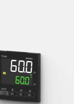
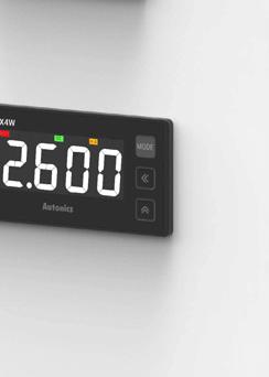


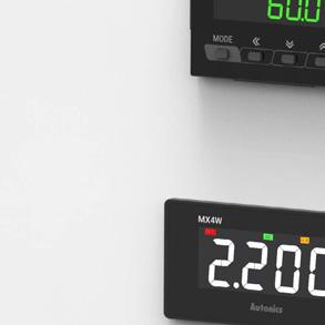


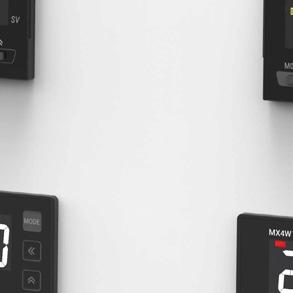


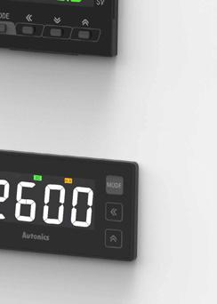

Autonics provide precise and stable temperature control system to meet customer needs in various environments. Temperature control is essential in modern industrial processes, and Autonics temperature control products play an important role in ensuring product quality and maximizing process efficiency. In particular, products are applied in temperature-sensitive industries such as semiconductors, automobiles, food, and packaging, improving optimal quality and user productivity.


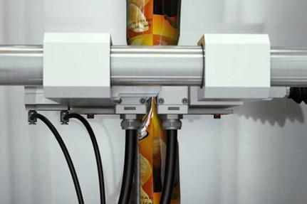
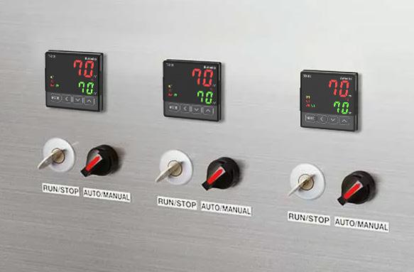
Chip Bag Filling, Sealing, and Cutting
High performance PID temperature controllers are used to control heater temperature fast for chip bag filling and sealing.
Temperature controllers are used to control the temperature of packaging material cutting machines.
3. Semiconductor/Display Industry
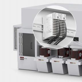
4. Machine Tools Industry
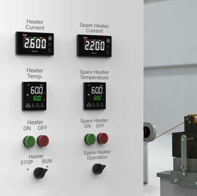
Semiconductor and Display Heat Regulators
Power controllers are used in semiconductor and display heat regulators which require precise temperature control.
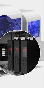

Edge Banding Machine
Temperature controllers are used to control heat levels for heating and melting solid adhesive when bonding bands to finish wood board edges.
Wire Extrusion Molding
Temperature controllers are used to control heat levels for raw material heating during wire extrusion molding process.
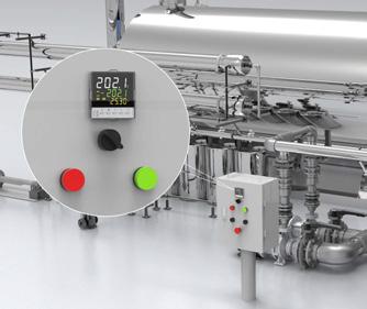
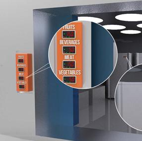
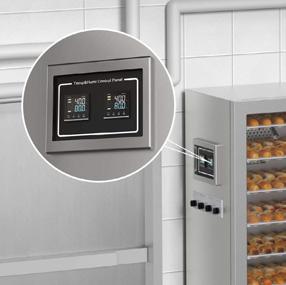

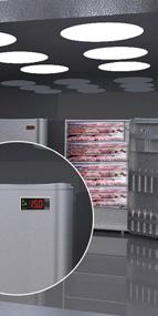
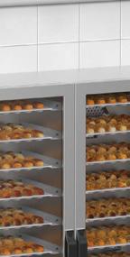
Temperature controllers are used to control appropriate temperature and time for each raw material to equalize the production quality.
Temperature controllers are used to control temperature of food storage refrigerators.
Temperature/humidity controllers are used to control and maintain appropriate temperature and humidity for dough fermentation in baking machines.
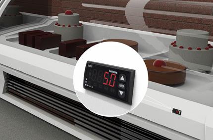
Temperature controllers are used to control temperature of food display refrigerators.


Temperature controllers are used to control temperature of commercial coffee roasters.
Temperature controllers are used to control and maintain appropriate temperature for sterilization in machines.
Korea (Headquarters)
39, Magokjungang 5-ro 1-gil, Gangseo-gu, Seoul, Republic of Korea, 07594
T 82-2-2048-1577
E sales@autonics.com
Germany
Autonics Germany Office T 49-6196-2048640
E germany@autonics.com
Japan
Autonics Japan Corporation
T 81-3-6435-8380 F 81-3-6435-8381
E ja@autonics.com
Türkiye
Autonics Otomasyon Ticaret Ltd. Sti. T 90-216-365-9117/3/4 F 90-216-365-9112
E turkiye@autonics.com
Brazil
Autonics do Brasil Comercial Importadora
e Exportadora LTDA
T 55-11-2307-8480 / 3195-4610 F 55-11-2309-7784
E comercial@autonics.com.br
India
Autonics Automation India Private Limited
T 91-22-2768-2570
E india@autonics.net.in
Malaysia
Mal-Autonics Sensor Sdn. Bhd. T 60-3-7805-7190 F 60-3-7805-7193
E malaysia@autonics.com
USA
Autonics USA, Inc. T 1-847-680-8160 F 1-847-680-8155 E sales@autonicsusa.net
China
Autonics Electronic (Jiaxing) Corporation
T 86-573-8216-1900 F 86-573-8216-1917
E china@autonics.net
Indonesia
PT. Autonics Indonesia
T 62-21-8088-8814/5
E indonesia@autonics.co.id
Mexico
Autonics Mexico S.A. DE C.V T 52-800-523-2131
E ventas05@autonics.com
Vietnam
Cong Ty Tnhh Autonics Vina T 84-28-3771-2662 F 84-28-3771-2663
E vietnam@autonics.com
Sensors, Controllers, Motion Devices, Safety, Measuring Equipment, Connection Equipment and more
• Photoelectric Sensors • Photomicro Sensors • Fiber Optic Sensors • Displacement Sensors • LiDAR • Ultrasonic Sensors • Door Sensors
• Area Sensors • Proximity Sensors • Linear Positioning Sensors • Rotary Encoders • Temperature Sensors • Temperature Transmitters
• Pressure Sensors • Pressure Transmitters
• Smart Camera
• Vision Sensors • Safety Light Curtains • Safety Door Switches • Safety Switches
• Safety Controllers • Safety I/O Terminal Blocks • Temperature Controllers • Solid State Relays • Power Controllers • Counters • Timers
• Digital Panel Meters • Digital Display Units • Sensor Controllers • SMPS • Industrial PC • HMIs • Recorders • Indicators • Network Converters
• Closed Loop Stepper Motor System
• 5-Phase Stepper Motor & Drivers
• 2-Phase Stepper Motor Drivers • Motion Controllers
• Industrial Networking • I/O Terminal Blocks • Distribution Boxes • Cables • Control Switches / Pilot Lights / Buzzers • Software
※ The dimensions or specifications on this product guide may change and some models may be discontinued without notice. 202501-Temperature Controllers-EN-01