Responsive environment Awnili Shabnam Design Studio: ATMOSPHERE, OCEAN: NO BLUE, NO GREEN
Something that is as vital to the sustenance of life as the oceans, that also scatters light to acquire its blue hue, is the atmosphere in which we live and breathe. In every cubic metre around us scientists tell us there are approximately 2.5 x 10 raised to the power of 25 molecules engaged in a restless and variable colliding interaction. We can’t see them, we can’t count them, we can’t model or simulate them, but we are sensitive in every way to what they are, and how they are behaving. We can manipulate them at the collective macro scale.
“No water, no life. No blue, no green” - Sylvia Earle
Table of Contents
Studio Directives
A. Pre-design research
A1. Atmospheric phenomenon: Precipitation
A2.Human perception
A3.Design precedent
B. Conceptualisation
B1.Group matrix
B2.Initial Idea
B3.Final proposal
C. Prototype Design: Automated Irrigation
C1.Initial idea
C2.Materialisation
C3.Final product
D. Prototype Design: Water collecting tower
D1.Initial idea
D2.Final product

The Designing Responsive Environments
Studio engages at the phenomenal level with the turbulent world of atmospheric dynamics that shape our environments leading to more subtly sensitive, responsive and energy conserving design solutions. In the ubiquitous computing era, designers can now capitalise on real-time data to inform their design. Dynamic phenomenal changes in the environment, such as light, temperature, humidity, air quality and movement can be traced with sensors and visualised to inform the design process. The opportunities come with the advent of off-the-shelf sensors, microelectronics, smart phones, new and smart materials, and augmented reality tools.
Aims of the Studio:
Studio Directives
• Deepen our understanding of Global Warming
• Understand why we are so deeply connected to it
• Find out whether, given that buildings and cities are the first cause, can they also be part of the solution? Can we, as designers be part of the solution?
• Explore radical and reachable approaches: cloud seeding, designing with and in symbiosis with atmosphere
A. Pre-design research
A1.Atmospheric phenomenon: Precipitation
Metamorphosis of water
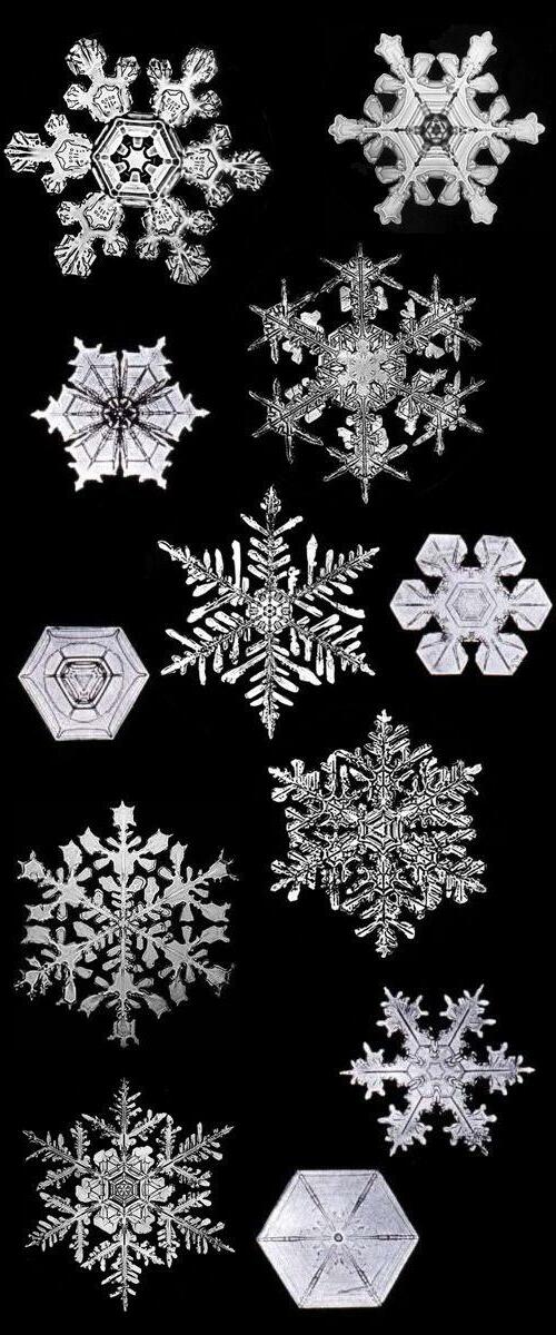
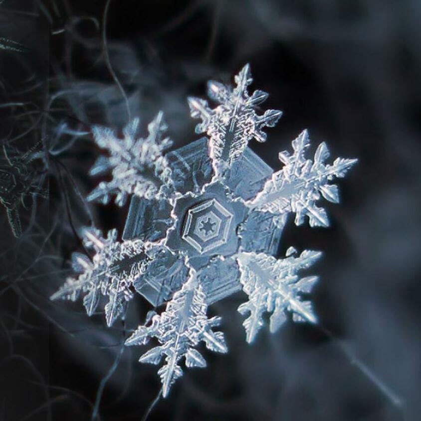
Water transforms continually from one form to another sustaining life on earth. The water cycle consists of evaporation and transpiration (evapotranspiration), condensation, precipitation, and runoff. precipitation is any product of the condensation of atmospheric water vapor that falls under gravity. It is a major component of the water cycle, and is responsible for depositing the fresh water on the planet. The main forms of precipitation include drizzle, rain, sleet, snow, graupel and hail.

Form of precipitation
Rain Sleet
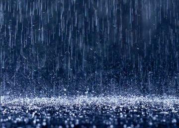
• Coalescence occurs when water droplets fuse to create larger water droplets, or when water droplets freeze onto an ice crystal, which is known as the Bergeron process.
• When air turbulence occurs, water droplets collide, producing larger droplets.
• As these larger water droplets descend, coalescence continues, so that drops become heavy enough to overcome air resistance and fall as rain
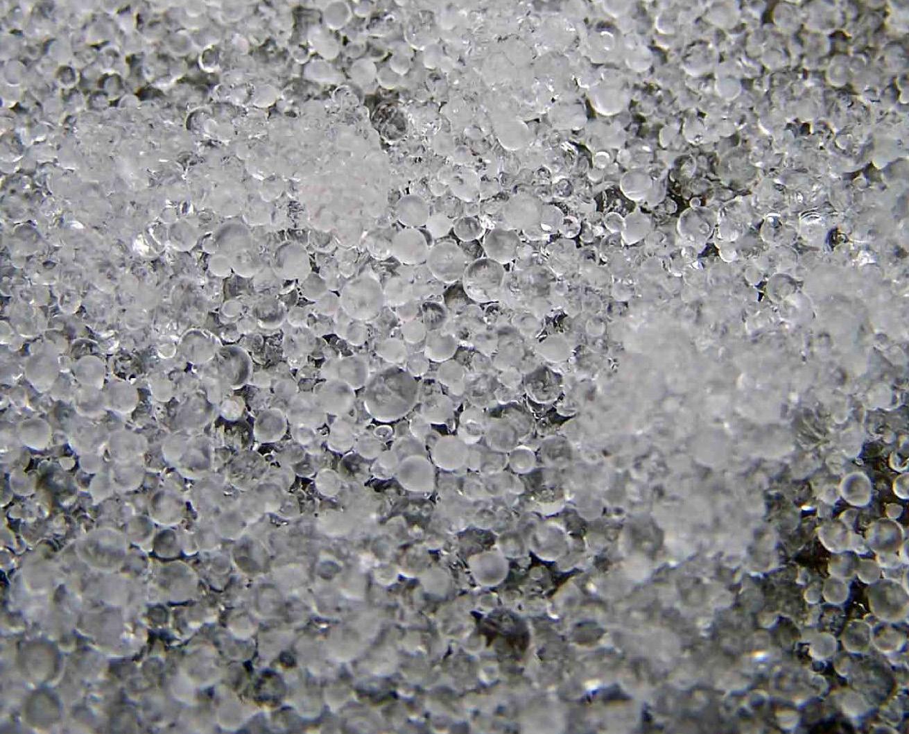
• Ice pellets or sleet are a form of precipitation consisting of small, translucent balls of ice. Ice pellets are usually (but not always) smaller than hailstones
Snow flakee Hail
• Snow crystals form when tiny supercooled cloud droplets (about 10 μm in diameter) freeze. Once a droplet has frozen, it grows in the supersaturated environment.

• Water droplets are more numerous than the ice crystals the crystals are able to grow to hundreds of micrometers in size at the expense of the water droplets.
• Hail forms in storm clouds when supercooled water droplets freeze on contact with condensation nuclei, such as dust or dirt.
• The storm's updraft blows the hailstones to the upper part of the cloud.
• The updraft dissipates and the hailstones fall down, back into the updraft, and are lifted again.

A2.Human perception
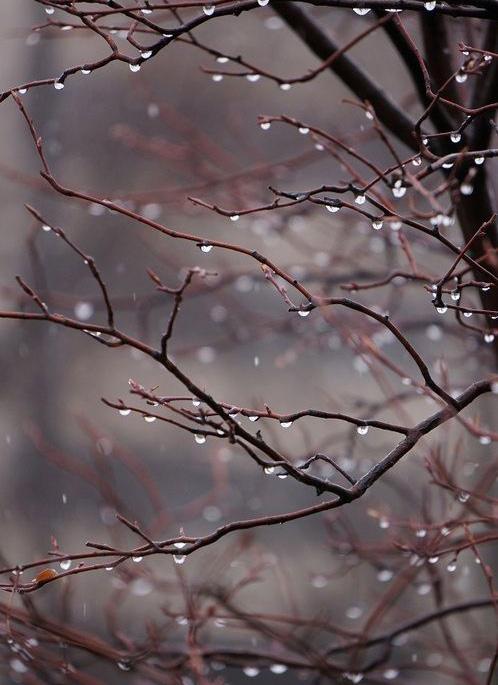
TACTILE

ACOUSTIC OLFACTIC


VISUAL
A3.Design precedent
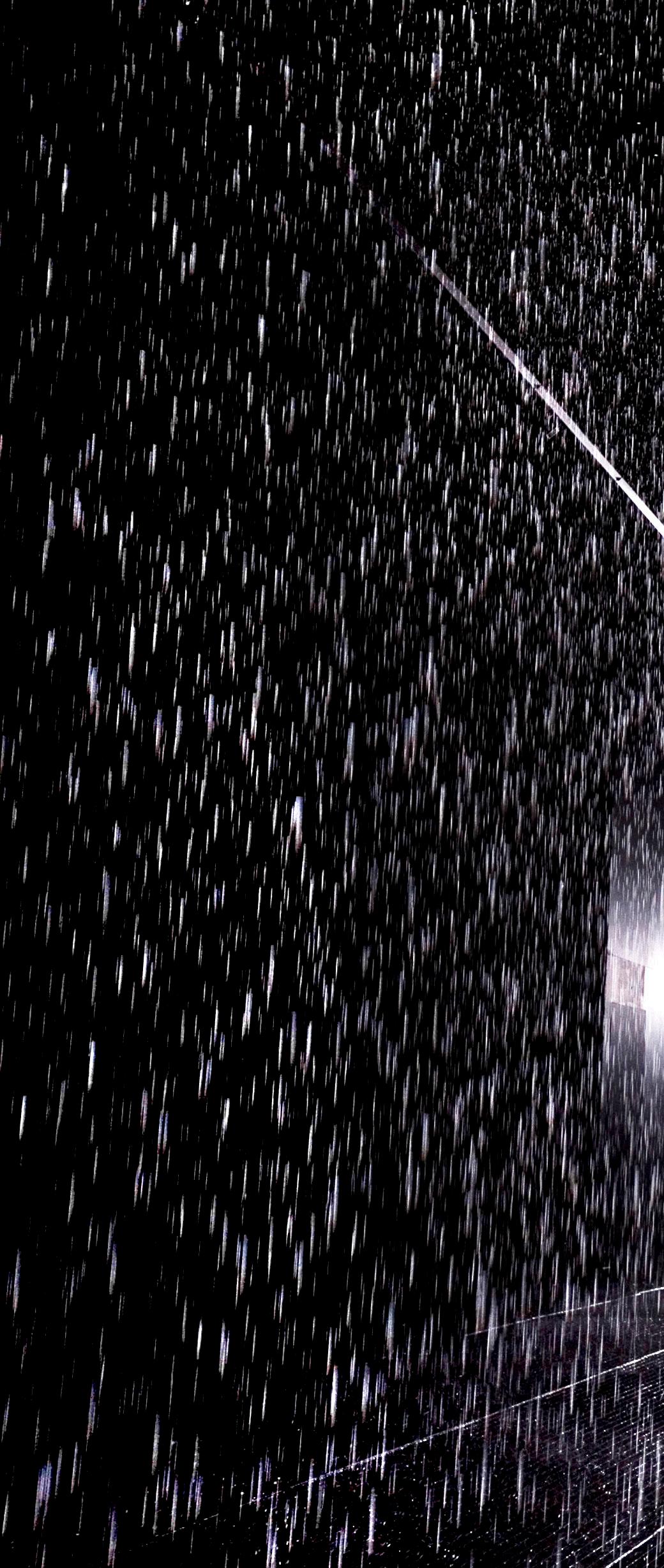
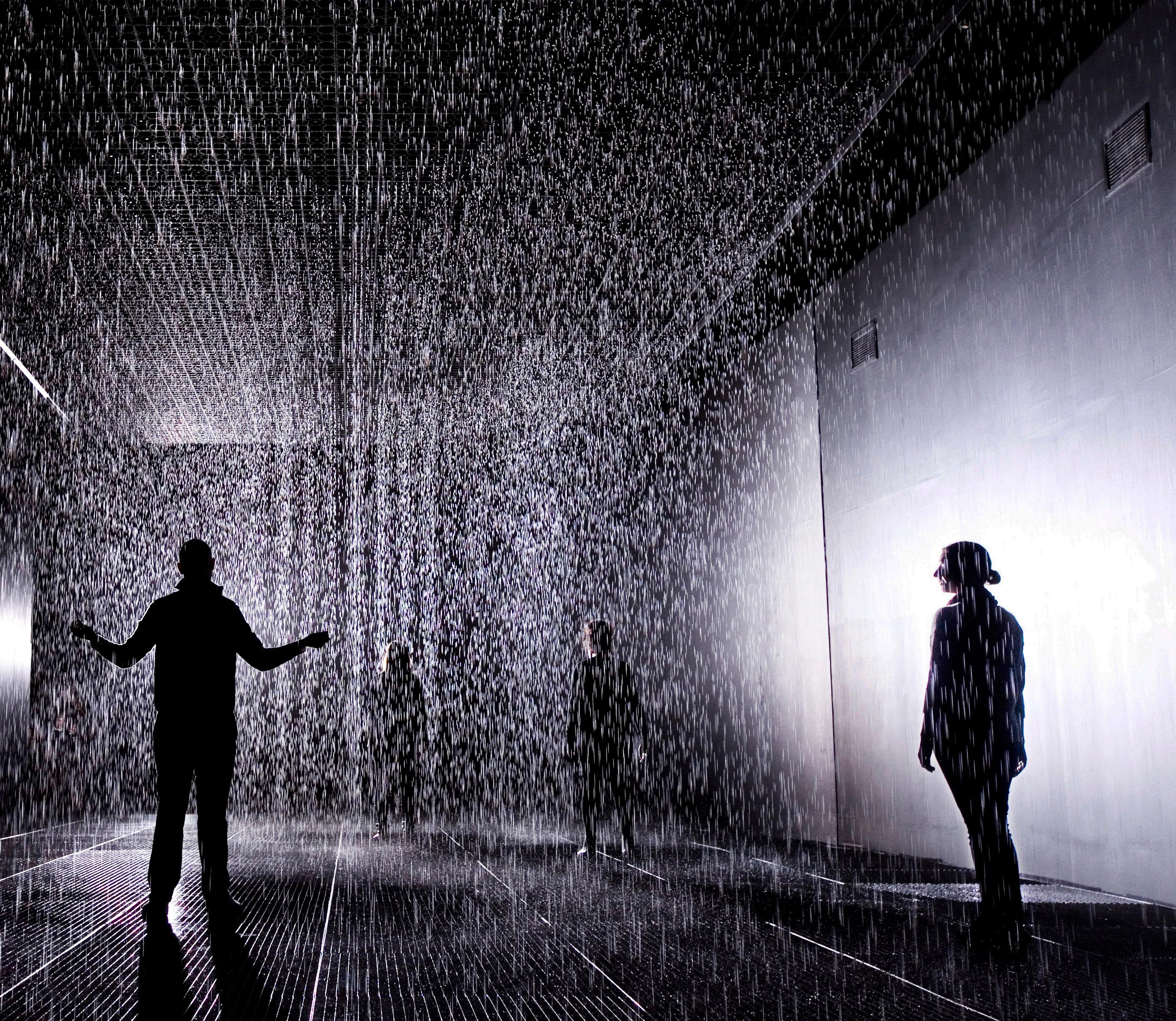
Random International: Rain Room
London
Rain Room is an environment of falling water through which it is possible to walk, trusting that a path can be navigated, without being drenched in the process. As you progress through the space the sound of water and a suggestion of moisture fill the air, before you are confronted by this carefully choreographed downpour that responds to your movements and presence. (1)
1. http://random-international.com/work/rainroom/
Canopy over Piazza Faber,Sardinia
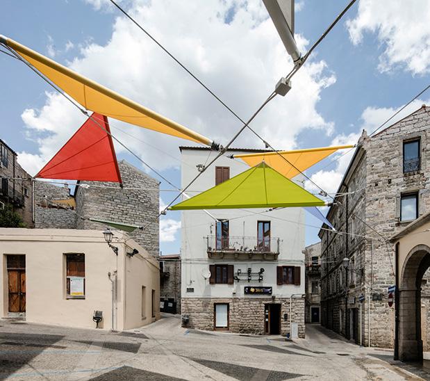
Renzo piano and alvisi kirimoto + partners
Renzo piano and alvisi kirimoto + partners have added a vibrant and ever-changing installation to the rustic piazza faber in sardinia the project comprises 12 suspended elements set against a backdrop of historical stone buildings and the market arcade. in celebration of the light and colors of the landscape, green, gold, red and blue fabric sails fluctuate in the air as if carried by the wind, finally resting on a web of wires that stretch between the buildings. The sails can be rolled up though a motorized system responding to climate condition. (2) 2. http://www.designboom.com/art/renzo-piano-alvisi-kirimoto-sardinia-sails-installation-piazza-faber-tempio-pausania-07-28-2016/


B. Conceptualisation
B1.Group Matrix
Terraforming Light
Fishing energy
Cloud Factory
Forest and water Fog
Salt
Transforming desert into forest
B2.Initial Idea
Forest
• Cool down forest in dry season
• Add biodiversity to the environment
• Use layering of trees(forest floor,under story canopy,emergent layer etc.) to suspend water as particles to increase humidity to nature
Cloud Precipitation
Artificially formed cloud causing precipitation
System of water containment & distribution
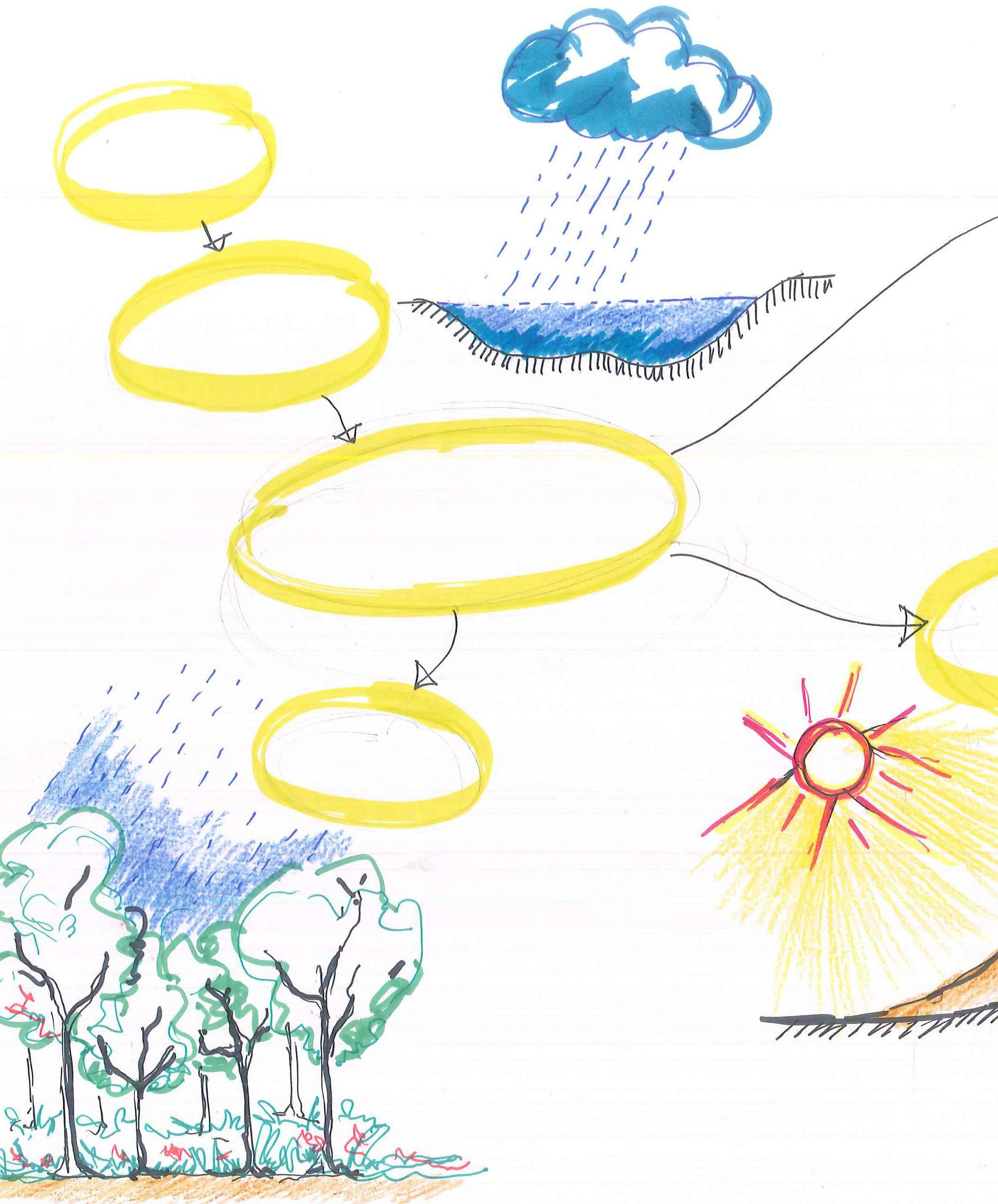
Desert
Forest
Phase 1
Desert
Human settlement
Human settlement
Urban heat canyon
• System to collect and use water inbuilt environment - building surfaces, installations, facades, transports.

• Storing water from precipitation toabsorb heat and cool down space reducing urban heat island effect
Desert
• Cntain water from precipitation
• Make environment humid to create habitat
• Improve soil for agriculture / firming
Green house over water reservoir
Transforming desert into forest
• Artificially formed cloud will be driven using curved surface from the city towards desert.

• In the desert rainfall will be induced by shooting particles at them
• Special trees will be grown to absorb more CO2
Phase 2

Apr Aug-Oct
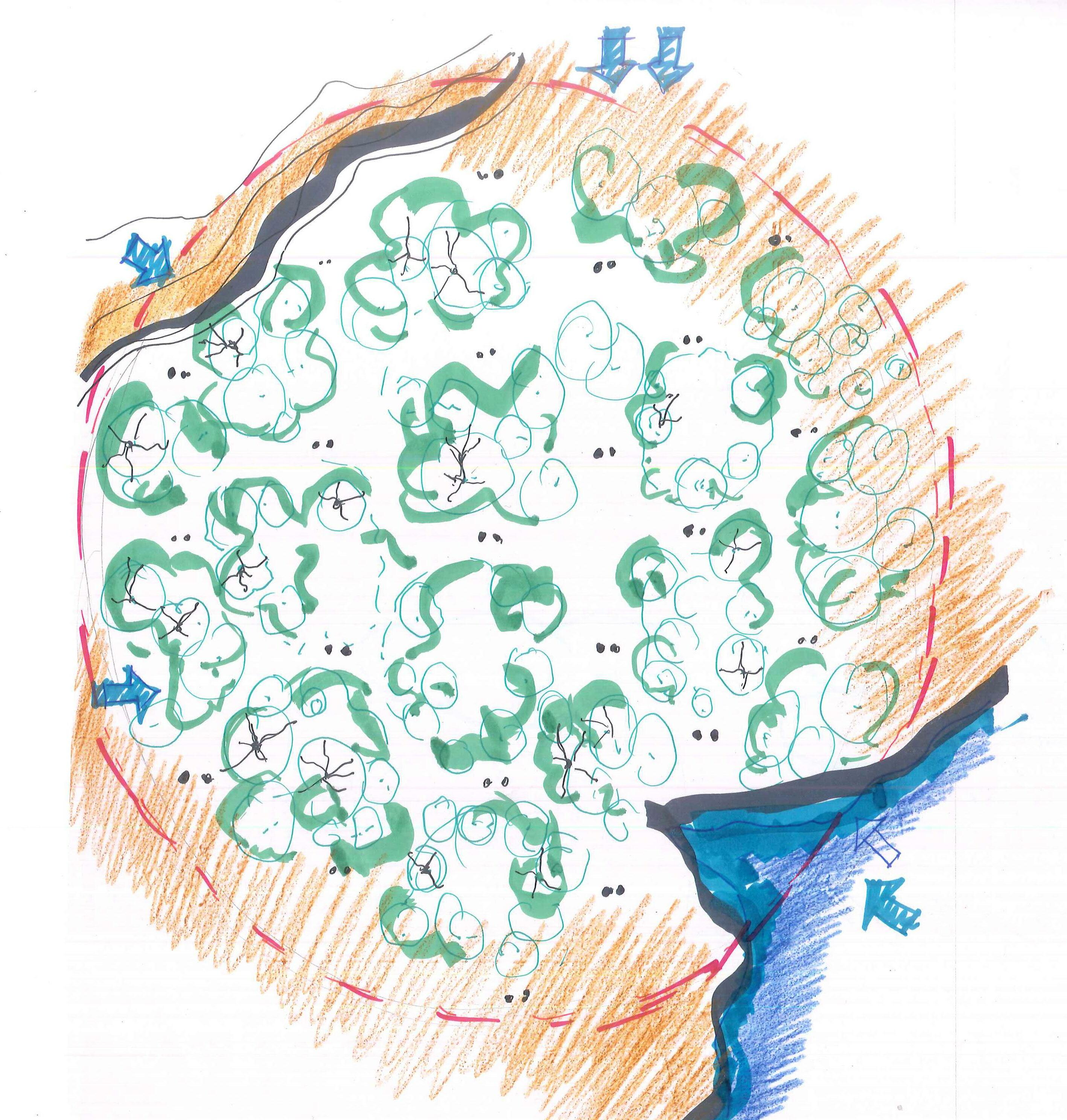
Layout for Cloud seeding machine positions considering wind direction
Ballarat
May-jul
Nov
Anakie
Layout for Cloud seeding machine positions considering wind direction
Geelong
Dec
Phase 3
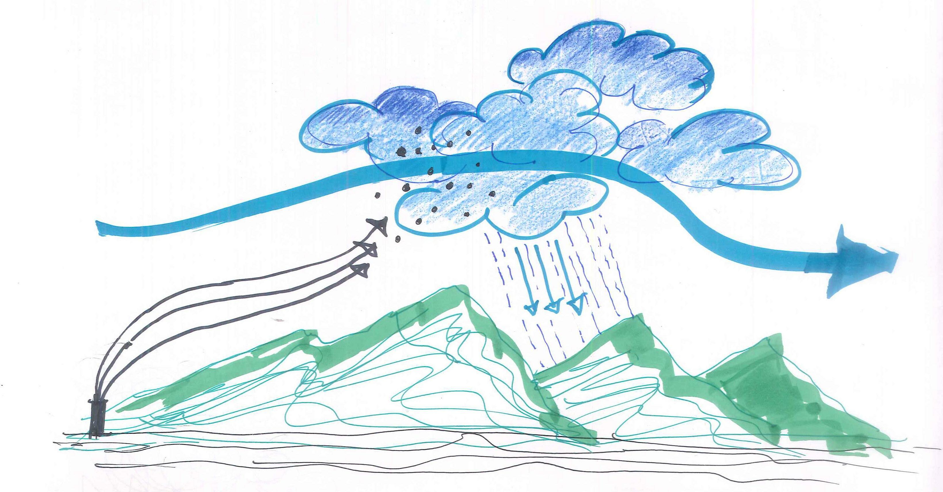
1.Shooting particles 2.Particles rise above the cloud 3.Particles condence the cloud to form ice crystais 4.Ice crystal grows big enough to precipitate Air flow
Schematic diagram explaining cloud seeding process
B3.Final Proposal
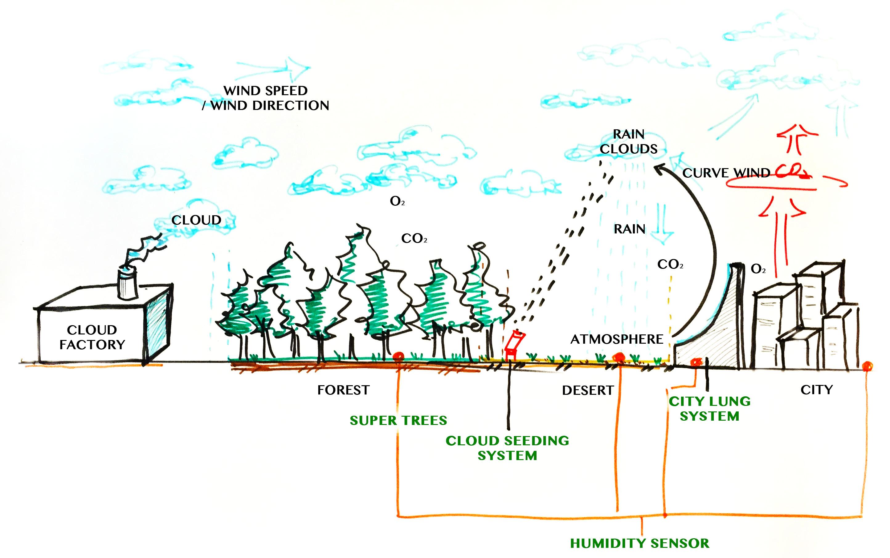
• The major concept is to transform the deserted area in between ocean and the city into lush forest vibrant with plants and animals
• he major concept is to transform the deserted area in between ocean and the city into lush forest vibrant with plants and animals
Transforming desert into forest
• The major concept is to transform the deserted area in between ocean and the city into lush forest vibrant with plants and animals
• The cloud factory will provide clouds with desired speed and direction
• When the clouds arrive at the edge between desert and city , the city lung machine will blow the curve wind and bring the clouds back to desert area.
• The cloud seedingmachine will shoot the cloud inducing precipitation.
• It will increase humidity of the soil to grow forest
• Special kind of trees are designed that can absorb more CO2 and release more O2 than regular trees ,
• Huge biomass created in the desert area will be used an energy for the cloud seeding machine
Group
System
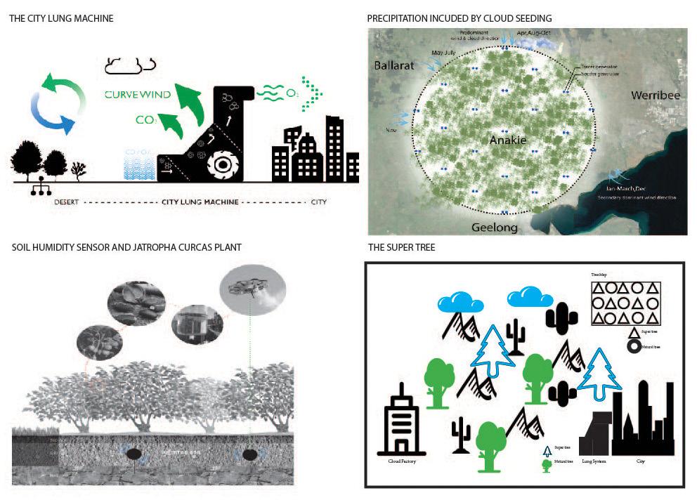
Integration of individual systems to form a wholistic approach
Individual System
Precipitation induced by cloud seeding

What is cloud seeding ?
Cloud seeding, a form of weather modification, is the attempt to change the amount or type of precipitation that falls from clouds, by dispersing substances into the air that serve as cloud condensation or ice nuclei, which alter the microphysical processes within the cloud.
Cloud seeding agents
1.Silver iodide is used as the glaciogenic (ice nucleating) seeding material because it has physical properties very similar to natural ice crystals
2. Indium (III) oxide is used as the inert tracer agent. The tracer particles are similar in size to the seeder particles; however they have no ice nucleating properties
Benefits of Cloud seeding
1.Artificially causing rain to facilitate habitation
2.Creating impact to reduce global warming
Cloud Seeding Process
QA_0710
Reference : SPERP Project report : CloudSeeding_
1. A comparatively dry and deserted area Anakie , in between Geelong and Ballarat is chosen as reference location
2. 30 km radius area is considered for the system operation
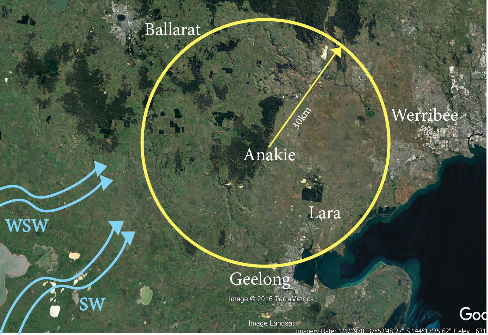
Site
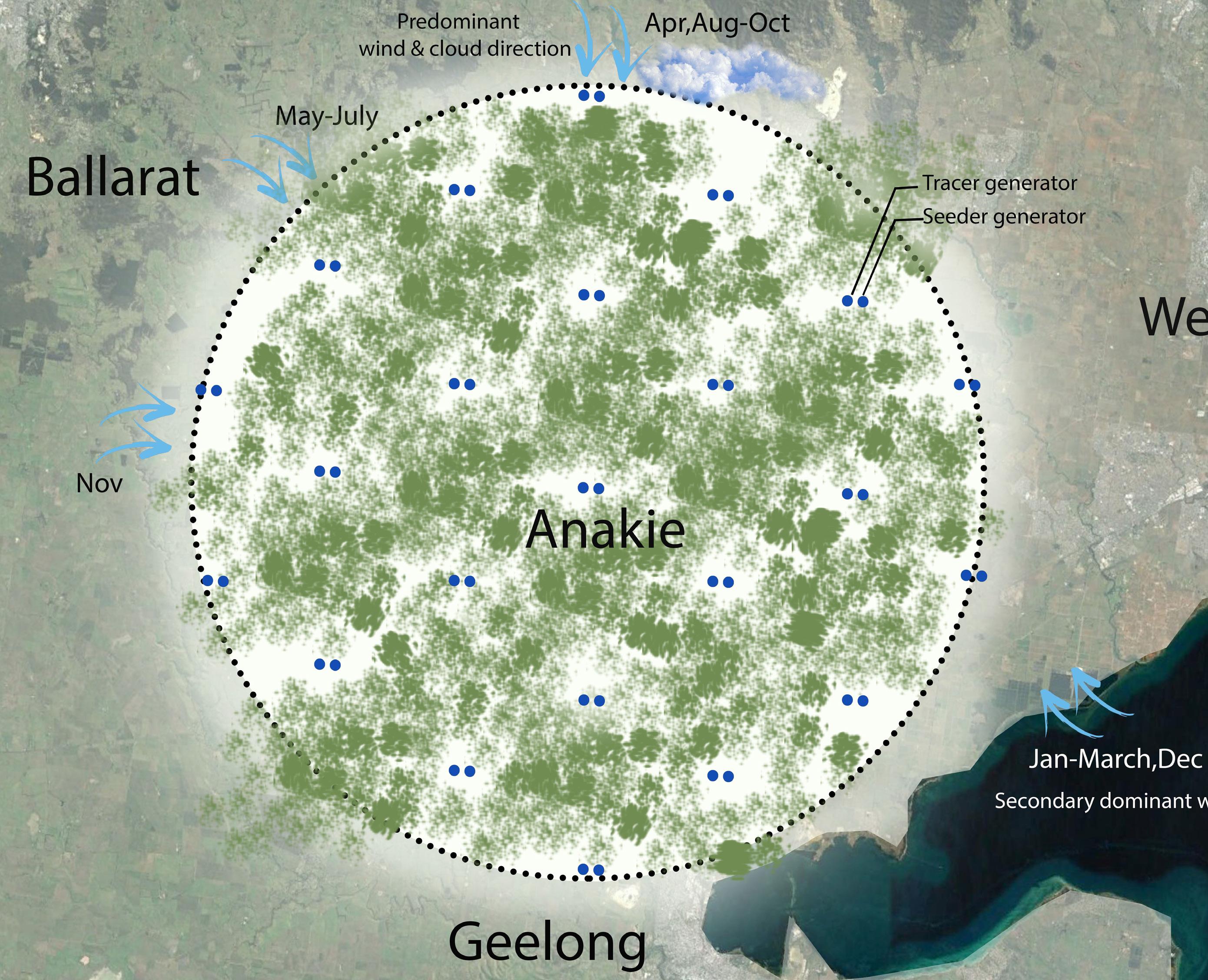
Individual System Layout
• The cloud seeding to induce rain depends on the direction and speed

• The wind pattern in Anakie region is subjected to major change depending on the time of the year
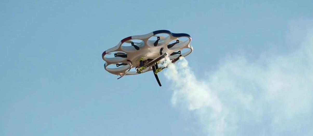
• A network of flying drones is proposed instead of fixed generators as it can be repositioned considering the change in wind direction
• The major wind direction is North-South , during Apr,Aug-Oct. Hence a layput of cloud seeding drones is suggested considering this wind direction
• This layout will guide the pattern of vegetation grown in the forest.
Drones Individual System
• 23 pairs of flying drones are launched
• Two drones are located at each site: one to disperse seeding particle and another for tracing particle
• Each drone burns 1.25 litre / hour producing 20 grams of Silver Iodide and 11 grams of Indium Oxide particles
Criteria
• Freezing level of 1600m
• Cloud top temp. -7 degree C or cooler
• Cloud depth greater than or equal to 400m above -5 degree C level.
• At least 15 drones are targeting
Schematic of biomass fuel plant to provide energy for cloud seeding operation
1.Inlet mixing tank for biomass and water 2.Stirrer with handle Biomass slurry 5.Stirrrer 4.Digester 3.Inlet pipe 6.Handle for 5 7.Gas outlet pipe 8.Damper for 9 9.Discharge window 10.Slurry discharge tank
Energy for the system
Particles
Cloud droplets Ice crystal
Silver Iodide
Individual System
C. Prototype Design: Automated Irrigation
C1.Initial Idea
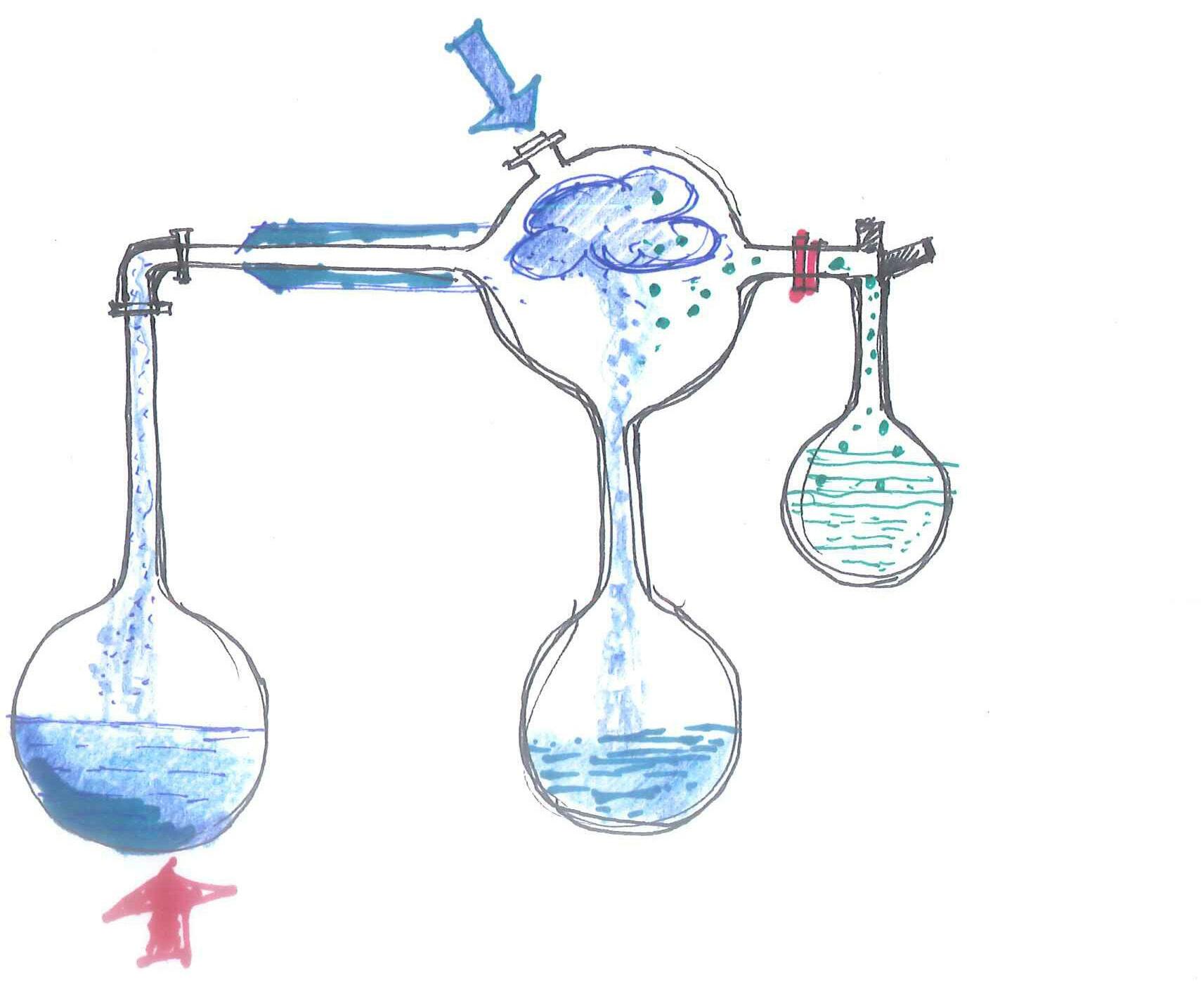
Phase
1 Heat Water Vapor Condensation Air pressure Precipitation Formation of cloud Cloud seeding agent (silver iodide/dry ice/ liquid propane)
Humidity censor Sprinkler
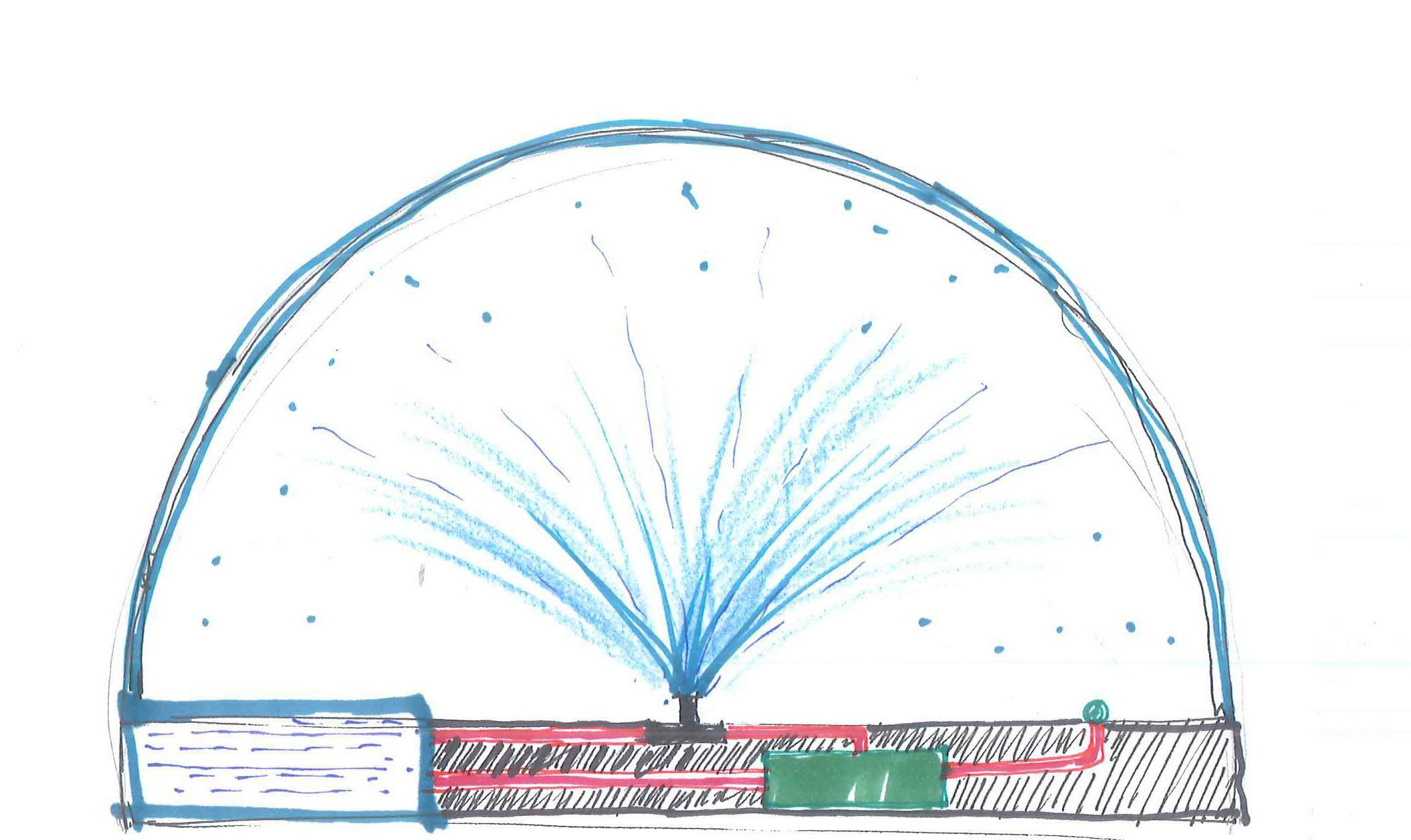
Water tank Water pamp
Phase 2
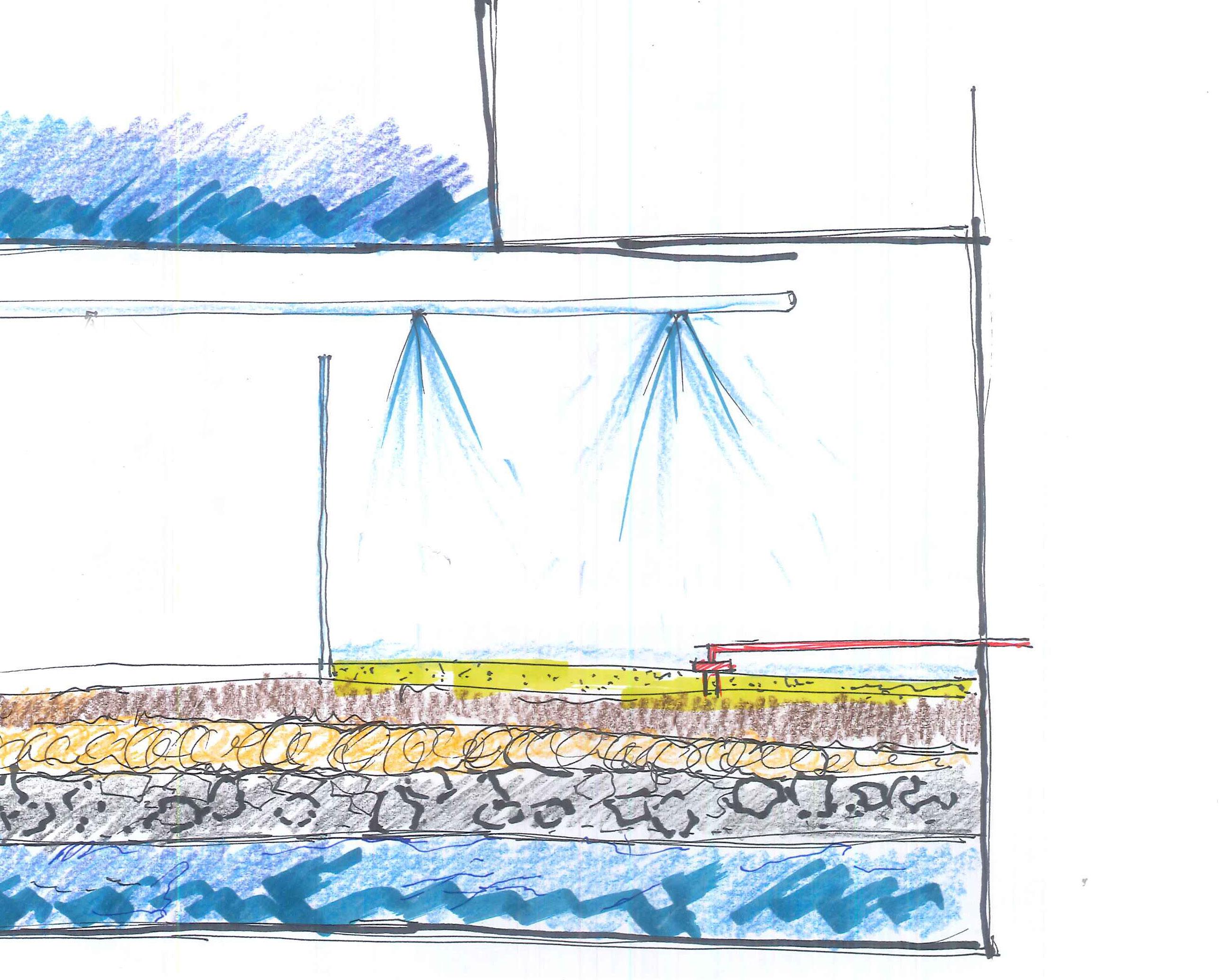
• The prototype comprises of two compartments- one with humid soil and another with dry sand representing forest floor and desert land respectively.
• A water tank is placed above the compartments to release water flow using gravitational force.
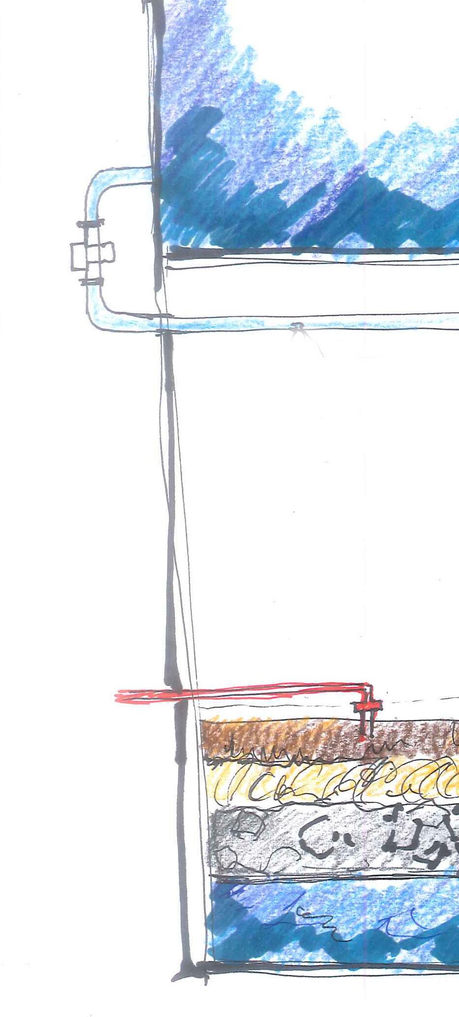
• Soil moisture cersor will detect the moisture level of the soil and send signal to a valve fitted to the water tank above.
• Depending on the soil moisture level the valve will operate and release water according to the need.
Water tank 2 Mesh Gravel Coconut fiber Soil
Water
Final proposal
Humid
tank 1 Solenoid valve Soil moisture sensor
Dry sand
Sprinklers
Humid
soil
Materialisation
C2.
Different phase of construction of the prototype

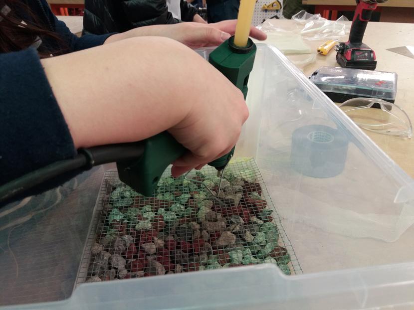
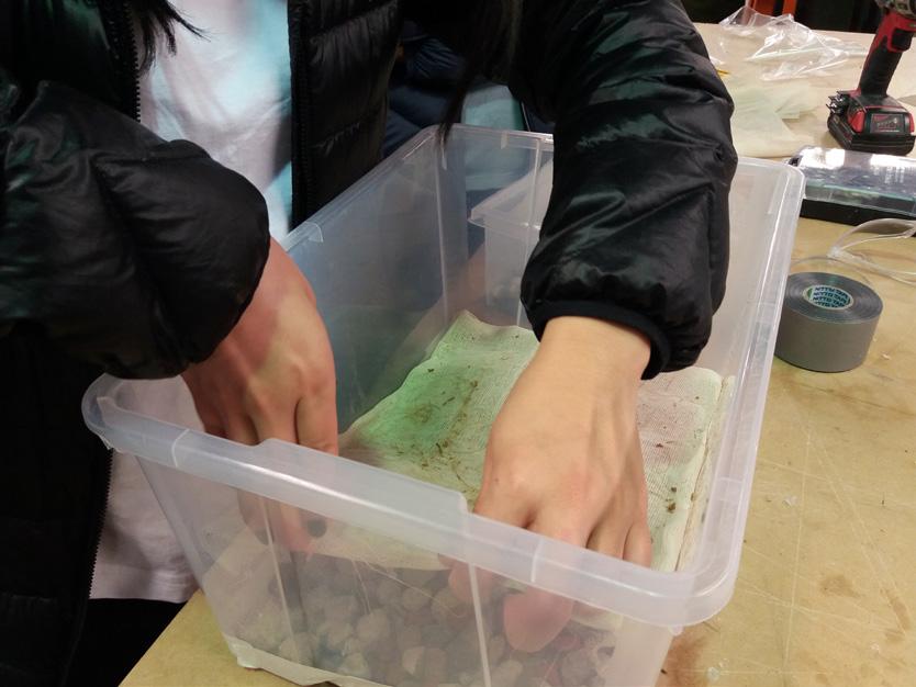

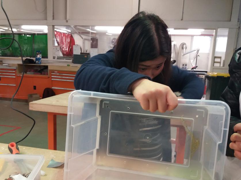
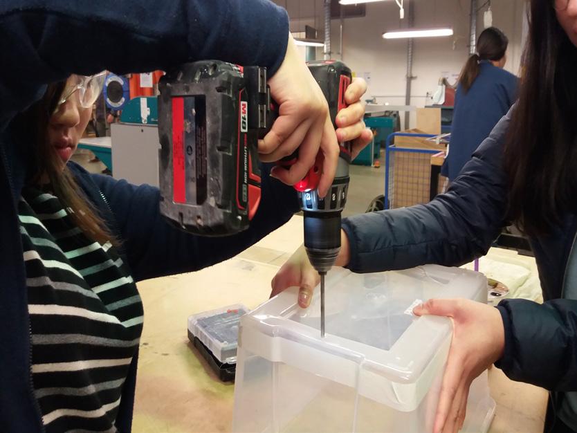
Construction
Compostion of soil layers in two compartments of the prototype

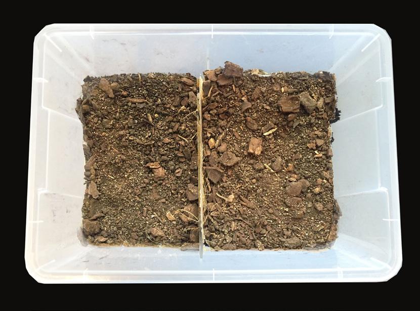

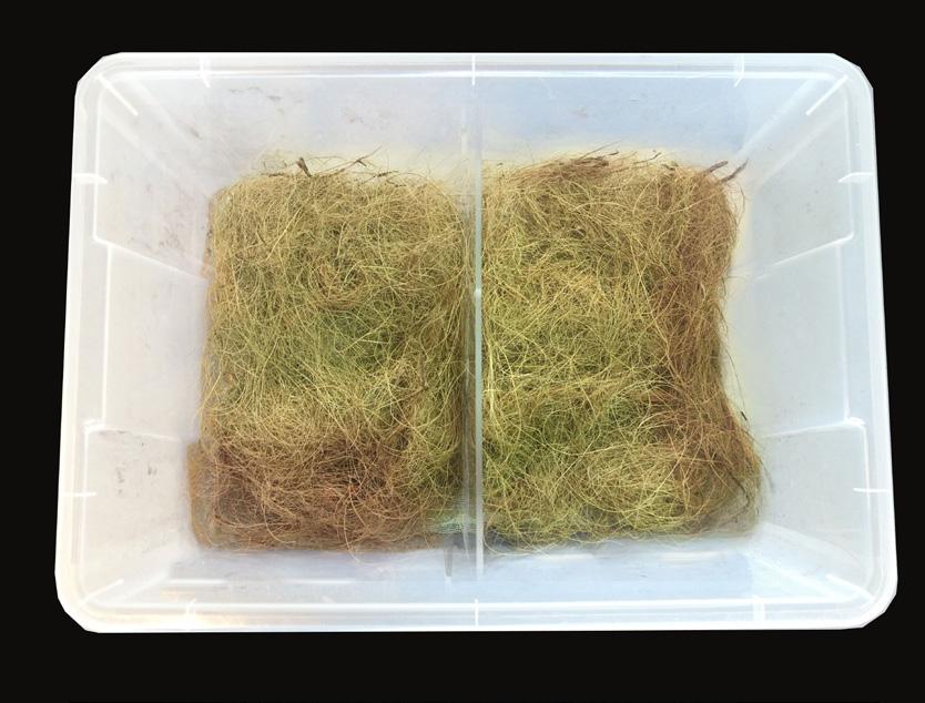
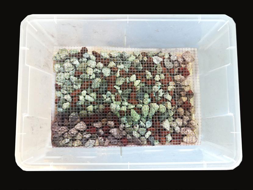
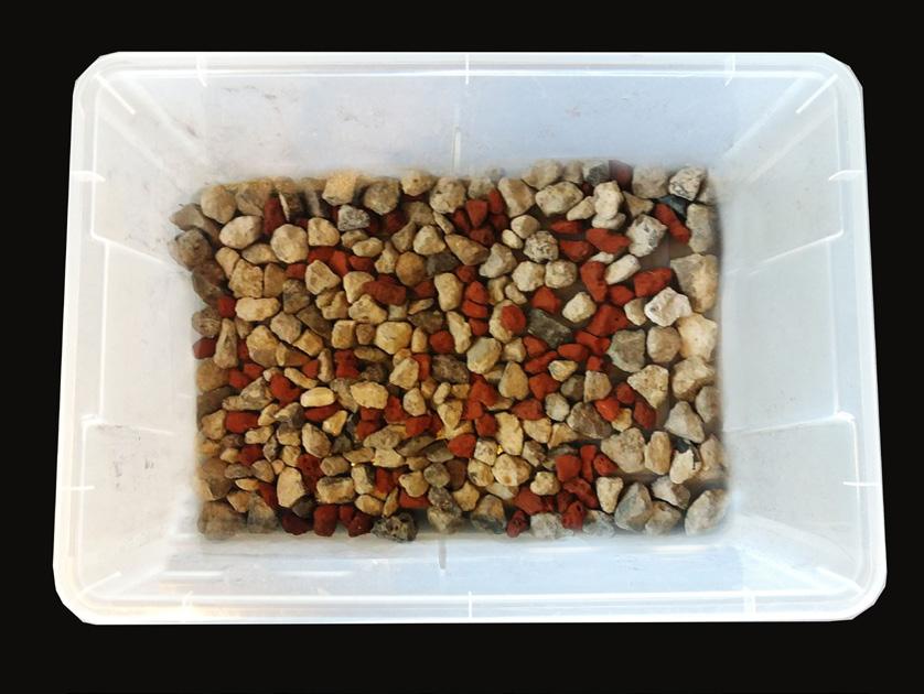
Connection diagram and arduino sketch

Arduino sketch
int sensorpin = A0; int outputpin = 13; int moisture; void setup() { Serial.begin(9600); pinMode(sensorpin, INPUT); pinMode(outputpin, OUTPUT); } void loop() { moisture = analogRead(sensorpin); Serial.println(moisture); /* digitalWrite(outputpin, HIGH); delay(3000);
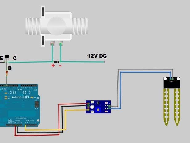
Connection
diagram
C3.Final product
Components
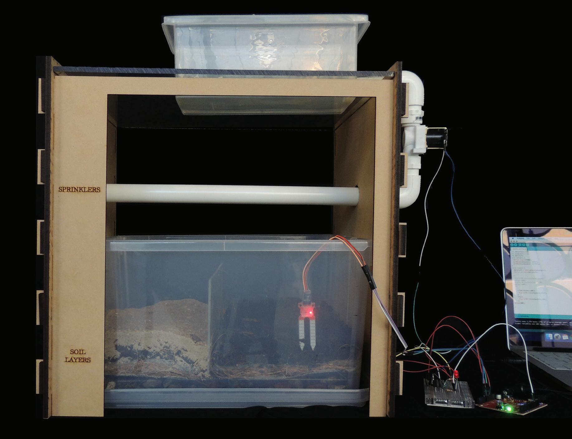
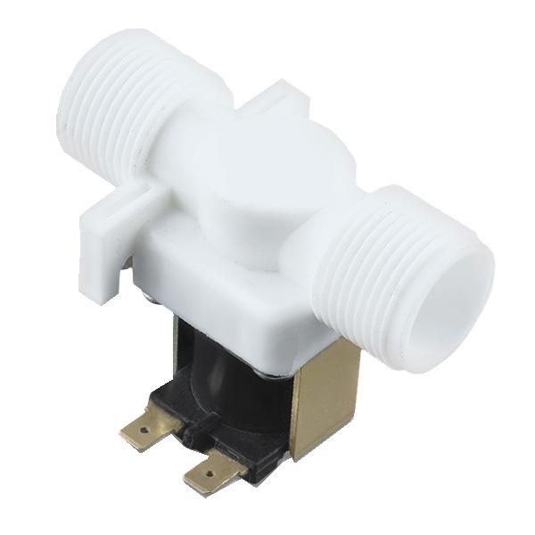
2.Valve will open or close after received commands from the soil moisture sensor.
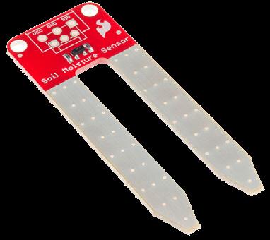
1.Soil moisture sensor detects the level of water contains in the soil. When soil is dry, it sends command to the valve to open and when the soil is wet, it sends command to the valve to stop the flow of water.
3. Arduino Redboard processor connects soil moisture sensor and solenoid valve

D. Prototype Design: Water collecting tower
D1. Initial Idea
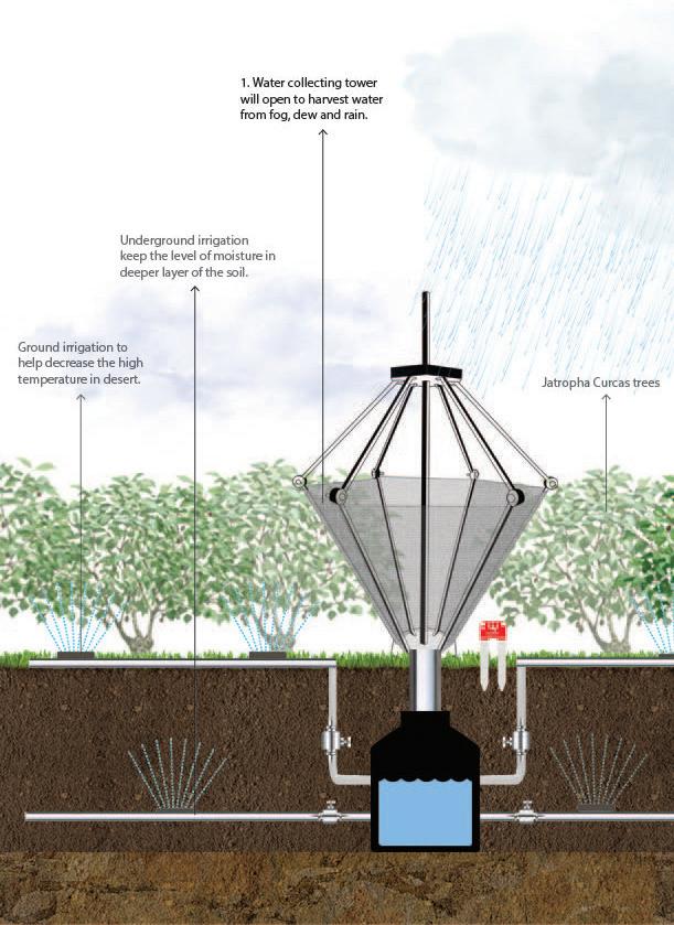
System

D2.Final product
Components
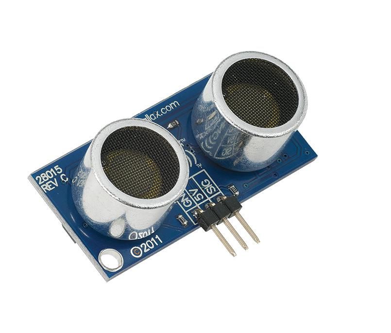
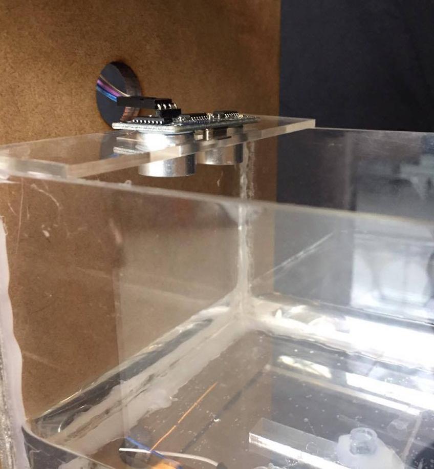
1.Ultrasonic sensor detects the water levelinside the tank and sends commands to the servo motor when the water level is low or high
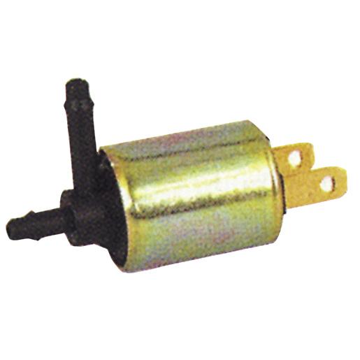
2.Underground solenoid valve will open or close according to the signal of soil moisture sensor
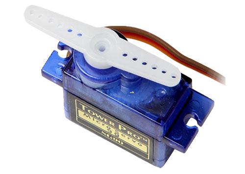
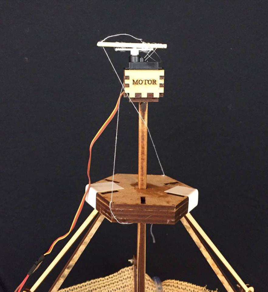
3.Servo motor works in response to the ultrasonic sensor to open and close the water collecting tower

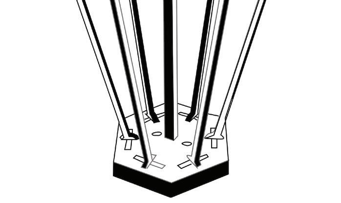
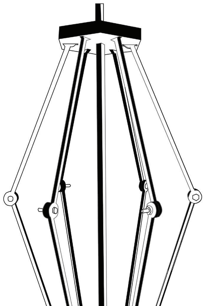
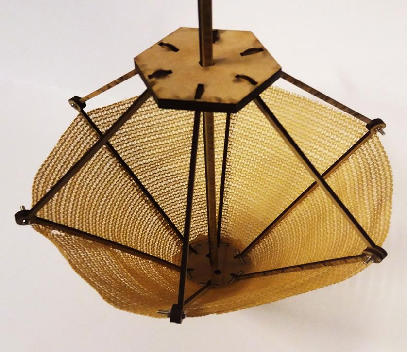
Structure
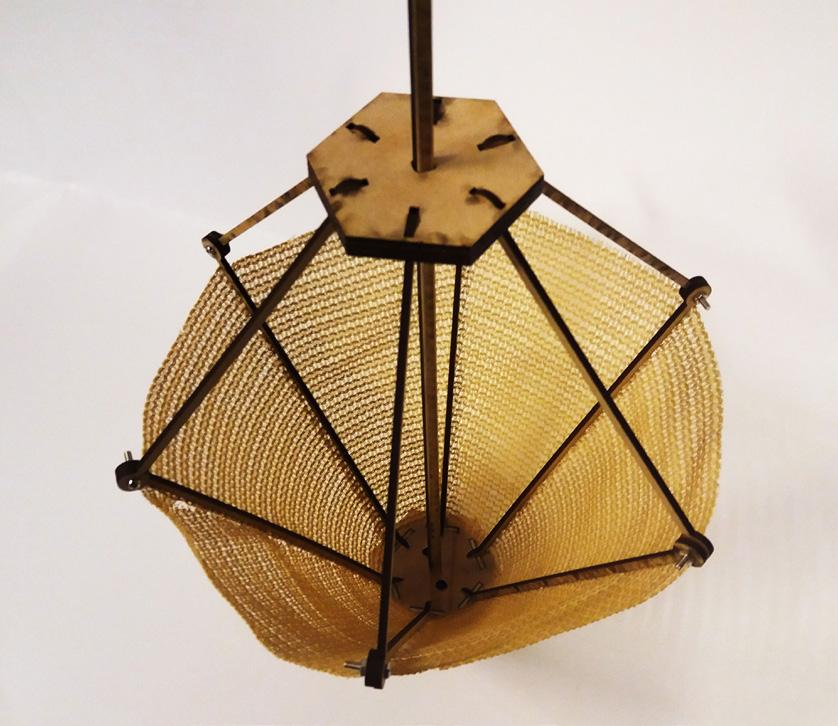
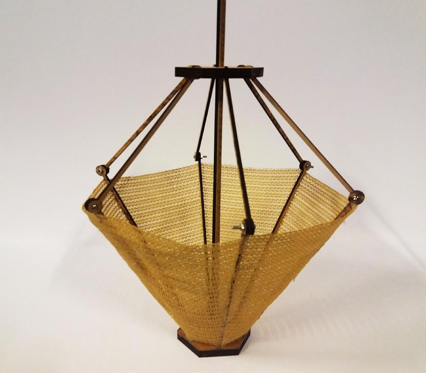
Provide structural strength and flexibility to open and close in response to the ultrasonic sensor/ water level sensor

Mesh
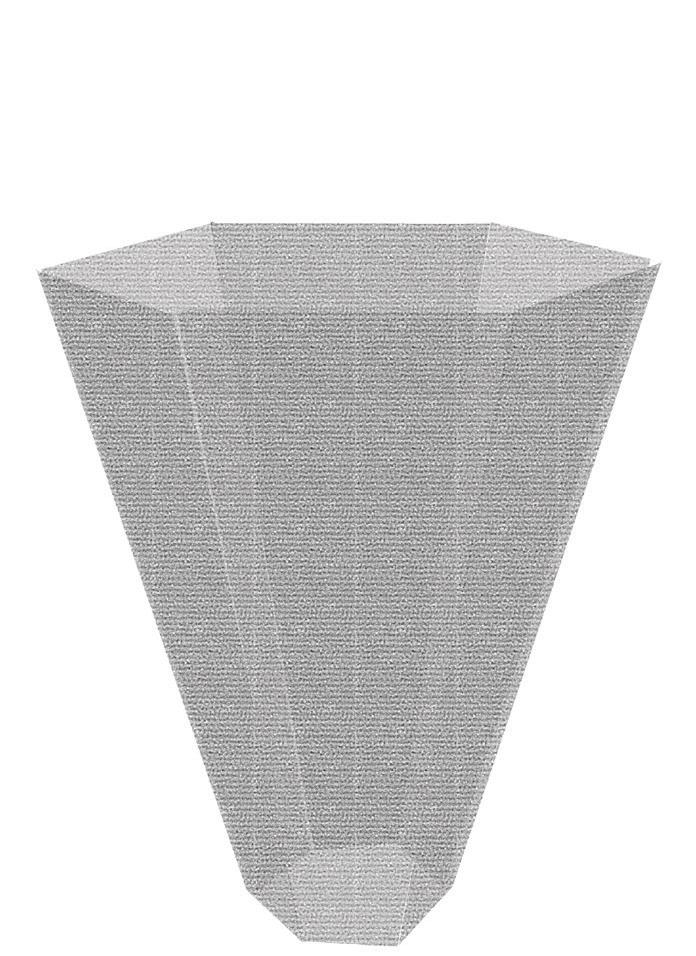
Allows air to pass through and captures water droplets which roll down by gravity
Collector Pipe Water tank
Falling water droplets from the mesh are catched by the collector and drainedto the pipe

The water pass through the pipe into the tank
A 3000L water tank is used to contain the harvested water

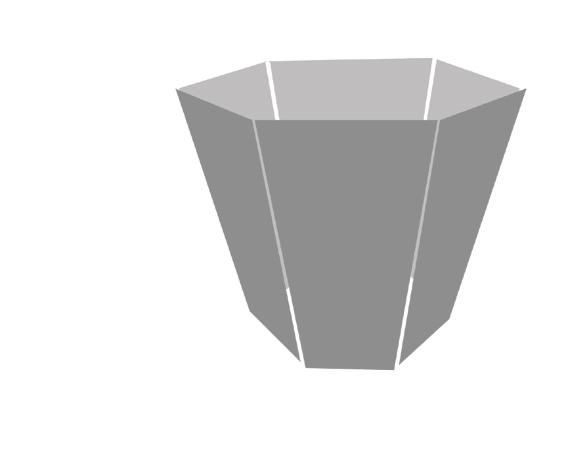
Components
Details of the water collection system

 Awnili Shabnam


 Awnili Shabnam


