
21 minute read
Building the internet of the future

The demand for data has been exploding over the past years and will continue to do so for this decade to come. How will our telecom networks cope? KPN has partnered up with Eindhoven University of Technology to look at that challenge from every angle.
Advertisement

Paul van Gerven
If there’s one sector that really shined during the corona crisis, it’s telecom. Reliable and high-speed internet connections kept large parts of the economy going and the quarantined entertained. is is only the beginning, however: many more opportunities are waiting to be unlocked by the beautiful marriage of telecom and digital services, ranging from self-driving cars to smart cities. is, however, places heavy demands on our wired and wireless networks, which will need to shuttle ever higher amounts of data back and forth, e ciently and a ordably. How will telecommunications companies make this happen, without letting energy demands get completely out of hand?
In a nutshell, this is what the public- private Smart collaboration is all about. Starting in 2017 with Smart One and recently expanded with Smart Two and Smart Two+, Eindhoven University of Technology (TUE) and telecom company KPN are elaborating what the internet of the future will look like, and what you can do with it.
Eavesdropping
Smart is an umbrella program, encompassing a wide range of research projects. “An eclectic approach is required because di erent aspects across communication systems tie into one another. e overarching goal of our systems is to deliver ever more relevant data to users, economically and energy e cient. is depends as much on the characteristics of the network infrastructure as it does on the various higher-level aspects,” says Ton Koonen, who leads the Electro- optical Communications research group at TUE and oversees several Smart projects.
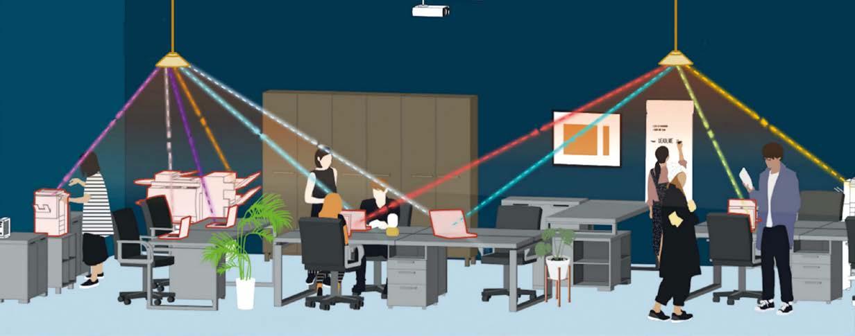
One example would be how network technology a ects security. Wireless connections are susceptible to eavesdropping because radio waves aren’t con ned to a particular place or space. It would be great if the practicality of a wireless connection could be combined with the inherent security of a wired one. is is the focus of one Smart project: extending optical signals from optical bers all the way to the living room (or any other room). Currently, optical signals tend to stop at the doorstep: as soon as they reach the building, they’re converted into electrical and radio signals for wired and Wi-Fi connections, respectively. Koonen’s group is working on ‘optical Wi-Fi,’ thus eliminating the need for signal conversions and enabling end-to-end optical connections.
In this system, signals are distributed by optical bers to ceiling-mounted antennas in di erent rooms. From there, they’re wirelessly transmitted to various devices using narrow infrared beams. Because these beams, unlike radio waves, are highly directional, eavesdropping is much more di cult. “In cases where very high security is needed, the windows could be coated with an infrared-blocking coating,” says Koonen. Other advantages of his optical wireless system include much higher data rates, lower latency and lower energy consumption, compared to regular Wi-Fi.
Outside our houses and o ces, radio waves networks will also face competition from other parts of the electromagnetic spectrum. In dense urban areas and crowded places like sports stadiums, 5G networks will harness the power of millimeter waves (mm-waves) to provide high-bandwidth wireless connections to a large number of people simultaneously. Wedged between microwave and infrared waves, mm-waves o er very fast data transfer, but at a cost: they don’t reach very far, they don’t bend around corners and they’re easily blocked by objects and even people. is last downside is being looked at by TUE’s Electromagnetics group. By studying the e ects of human movement on the quality of mm-wave transmission, researchers expect to obtain clues about how to build mm-wave base stations that minimize this type of blocking. ey’ll also gain
High tech highlights
A series of public-private success stories by Bits&Chips
Credit: TU Eindhoven/Bart van Overbeeke
insight into where to best place the base stations.
Semantic data

A perhaps surprising element that enters into the equation when considering the communication systems of the future is architecture. e way our houses and buildings are constructed a ects the kind of communication systems we can set up in there and hence what services can or cannot be provided. at’s why there are also Smart research projects performed together with TUE’s Department of the Built Environment.
In terms of networking ICT, houses and buildings are the most heterogeneous environments, adds Nico Baken, strategist at KPN, part-time professor in Koonen’s research group and initiator of the Smart collaborations. “ at makes them the most challenging environments for a company like KPN. e problem is: we don’t know much about them. It would enable great new possibilities if we had a kind of ngerprint, a kind of genome, of all our houses and o ces. at would considerably help with designing the ideal network for them.”
Particularly in smart buildings, in which heating, ventilation, air conditioning and lighting are controlled down to individual rooms and user preferences, it’s not just about the network and the sensors collecting the data, but also about data handling. Bringing together streams of di erent types of data is by no means trivial – current methods are not yet fully capable of doing that. at’s why researchers at TUE’s Department of the Built Environment are studying digital representations of buildings that can integrate all the information. ese digital twins (or, in this case, building twins) link di erent data models to improve monitoring, decision-making, automation, optimization and individualized control of buildings. is will improve user comfort while reducing energy consumption.
Another project at the Department of the Built Environment is about self- driving cars, and, more speci cally, about how they can safely nd their ways around cities and highways. is, too, isn’t just a matter of hardware (network infrastructure and processors at various levels), it also requires new ways to handle data. e Smart researchers are looking into using so-called semantic data models for handling mobility-related data in the future. Essentially, these models, constructed using promising new techniques that are also used for building the next generation of the internet (Web 3.0), add context-related meaning to the data and the relationships between them. is allows for seamlessly
Credit: TU Eindhoven
One of the Smart projects is working on ‘optical Wi-Fi.’ In this system, signals are distributed by optical fi bers to ceilingmounted antennas in different rooms. From there, they’re wirelessly transmitted to various devices using narrow infrared beams.
linking and integrating di erent data sources, which will contribute to a safer and more e cient tra c ecosystem.
Very happy
ough future oriented, some Smart research is already paying o for KPN. “Especially in arti cial intelligence, we enjoy the fruits of the program. anks to AI, we’re able to spot issues before they become big problems, so we can x them before the customer even notices,” says Baken.
Even if most research results need a couple of years of maturation before KPN can take advantage of them, they’re very valuable for his company, stresses Baken. “ ere’s pro t and there’s value. We do not work with universities for an immediate pro t, we’re in it for the value. It allows us to see more of the future, which helps us to determine which directions to take. Recently at KPN, we made a systematic inventory of our needs. ese turn out to align beautifully with the research projects we’re involved in, so we’re very happy.”
For his part, Koonen considers working with industry to be a natural phenomenon. “Before joining TUE, I worked in industrial research environments for over twenty years. So, like many of my colleagues here, I have many connections in industry. And that’s how it should be: we want our students to understand how to connect knowledge and skills with applications. After all, the technology that we’re working on here is meant to be applied.”


Online
Online
Online
New
Online
Online SOFT SKILLS & LEADERSHIP
Neurodiversity @work: coping with autistic characteristics in the technical world
20 May 2021 (1 half day) Time management in innovation
Starts 25 May 2021 (1,5 day) Presentation and body language skills
Starts 25 May 2021 (3 morning sessions) Leadership skills for architects and other technical leaders
Starts 31 May 2021 (2 times 2 days + evening sessions) Eff ective communication skills for technology professionals – part 1
Starts 7 June 2021 (3 days + 1 evening) Presentation and body language skills
Starts 22 June 2021 (3 sessions of 2,5 hours + e-learning) How to be successful in the Dutch high tech work culture
1 July 2021 (1 day) Eff ective communication skills for technology professionals – part 2
Starts 7 July 2021 (3 days + 1 evening) System architecting masters
Starts 4 October 2021 (nine-month program) Consultative selling for technology professionals
Starts 4 November 2021 (2 days + 1 evening session)
ELECTRONICS
Electronics cooling thermal design
Starts 31 May 2021 (5 consecutive mornings) EMC for motion systems
Starts 23 June 2021 (3 consecutive days) Advanced thermal management of electronics
28 June – 1 July 2021 (4 consecutive afternoons) Test and design-for-test for digital integrated circuits
Starts 7 September 2021 (3 consecutive days) EMC for mechatronic engineers
9 September 2021 (1 day) EMC design techniques
Starts 20 September 2021 (4,5 consecutive days) Signal integrity of a PCB
Starts 20 September 2021 (2,5 consecutive days) Microelectromechanical systems
Starts 28 September 2021 (3 consecutive days) Solid State generated RF and applications
29 September – 1 October (3 consecutive days) Switch-mode power supplies
Starts 5 October 2021 (2 times 3 consecutive days) Thermal design and cooling of electronics
Starts 3 November 2021 (3 consecutive days)
MECHATRONICS
Motion control tuning
Starts 14 June 2021 (5 consecutive days) Thermal eff ects in mechatronic systems
Starts 15 June 2021 (3 consecutive days) Design principles for precision engineering
Starts 21 June 2021 (5 consecutive days) Advanced feedforward and learning control
Starts 23 June 2021 (3 consecutive days) Actuation and power electronics
Starts 29 June 2021 (3 consecutive days) New
New Experimental techniques in mechatronics
Starts 5 July 2021 (3 consecutive days) Advanced motion control
Starts 11 October 2021 (5 consecutive days) Mechatronics system design – part 1
Starts 11 October 2021 (5 consecutive days) Metrology and calibration of mechatronic systems
Starts 2 November 2021 (3 consecutive days) Mechatronics system design – part 2
Starts 8 November 2021 (5 consecutive days) Passive damping for high tech systems
Starts 23 November 2021 (3 consecutive days) Dynamics and modelling
Starts 30 November 2021 (3 consecutive days)
OPTICS
Modern optics for optical designers – Part 2
Starts 10 September 2021 (15 weekly morning sessions) Applied optics
Starts 1 November 2021 (15 weekly afternoons) Modern optics for optical designers – Part 1
Expected February 2022 (15 weekly morning sessions)
SOFTWARE
Object-oriented analysis & design – fast track
Starts 25 May 2021 (4 consecutive days) Multicore programming in C++
Starts 7 June 2021 (3 consecutive days) Design patterns and emergent architecture
Starts 21 June 2021 (4 consecutive days) Speed, data and ecosystems
Starts 13 October 2021 (2 consecutive days) Good software architecture
Starts 9 November 2021 (2 times 2 days) Software engineering for non-software engineers
Starts 23 November 2021 (2 evening sessions) Secure coding in C and C++
Starts 29 November 2021 (3 consecutive days)
SYSTEMS
Value-cost ratio improvement by value engineering
Starts 20 May 2021 (2 consecutive days) System requirements engineering improvement
Starts 27 May 2021 (2 consecutive days) System architect(ing) in Eindhoven
Starts 31 May 2021 (5 consecutive days) Introduction to SysML
28 June 2021 (1 day) Design for sustainability
2 + 9 September 2021 (2 days in 2 weeks) Design for manufacturing
Starts 30 September 2021 (3 days in 3 weeks) System architecting masters
Starts 4 October 2021 (nine-month program) System architect(ing) in Zwolle
Starts 11 October 2021 (5 consecutive days) Introduction to deep learning
Starts 9 November 2021 (1 day) System architect(ing) in Eindhoven
Starts 15 November 2021 (5 consecutive days)
Cees Links is a Wi-Fi pioneer and the founder and CEO of Greenpeak Technologies and currently General Manager of Qorvo’s Wireless Connectivity business unit.

Wi-Fi 6E: the new kid on the block
The Wi-Fi 6 standard runs in the so-called unlicensed, low-power 2.4 GHz and 5 GHz frequency bands. These bands have been in place since the beginning of this century following quite a long process, as each country has the autonomy to assign band usage within its own territory. In the years running up to 2020, the Wi-Fi industry has worked with about 80 MHz in the 2.4 GHz space and 580 MHz in the 5 GHz space – 660 MHz in total.
There are two possibilities to get more data at higher speeds through the air: more bandwidth (more frequency bands) or more sophisticated radio communication (more megabits per MHz). Over the last 20 years and several generations of Wi-Fi, the data rate has increased by using more advanced radio technologies. The original 11 Mb/s of 802.11b was followed by 802.11a, 802.11g, 802.11n, and so on, with the data rate going up into the multi-gigabits per second. At the same time, the calls grew louder for the governments to provide more unlicensed spectrum.
Around 2010, a new frequency band was made available in the 60 GHz space with a lot of spectrum and a lot of bandwidth – almost 13 GHz. The idea was to be able to go to very high data rates – and indeed, Gb/s were achieved. A standard was even developed, called Wi-Gig or IEEE 802.11ad. But the range, about 3 meters, was disappointing. As the number of applications requiring very high speeds over very short distances (‘Bluetooth on steroids’) was limited, the usage of the 60 GHz space hasn’t gotten much commercial traction.
In 2019, there was worldwide momentum to make 6 GHz available as a low-power unlicensed band because several applications using 6 GHz had started to fade away. This coincided with reports showing the economic value of Wi-Fi returning in taxed profits, taking away the concerns about ‘giving away’ spectrum to the industry. Governments prefer to license spectrum, so they can immediately monetize the usage in license
fees, while unlicensed spectrum is only indirectly monetized through taxes on economic activity generated through the usage of that spectrum. In the US, there was strong momentum to match the amount of spectrum licensed for 5G with a comparable amount of unlicensed spectrum for low-power, indoor applications, of which Wi-Fi is one of the best known. This led in April 2020 to the FCC announcement to ‘un-license’ the 6 GHz band for low-power usage. And thus, Wi-Fi 6E was born – the new Wi-Fi standard that extends WiFi 6 into the 6 GHz space. The 1,200 MHz of available bandwidth is a sizable extension compared to the combined 660 MHz that was available previously. Initially, we’ll only see Wi-Fi 6E as an increase in capacity – the number of Wi-Fi connections that can be used at the same time (eg more users in the home using demanding networking applications, including video and gaming). The real next steps in higher data rate, together with exploiting the higher capacity, will be made when Wi-Fi 7 comes into fruition.
Other countries have picked up the challenge. The end of 2020 saw a growing list of locations where WiFi 6E technology can be applied. In Europe, the UK took the lead and via the ETSI, the rest of the continent is expected to follow. (In Europe, at least for now, only the lower part of the 6 GHz space will be made unlicensed – about 500 MHz.) South Korea and several South American countries (Brazil, Chile, Peru) have decided to follow America’s 6E expansion.
Furthermore, the FCC has proposed to add a 45 MHz band to the 5 GHz unlicensed spectrum. With 1,200 MHz available in the 6 GHz space, why is this important? Because the available unlicensed 580 MHz in the 5 GHz spectrum was just falling short of being able to accommodate three simultaneous high-speed 5 GHz channels. The additional 45 MHz solves that problem, allowing the development of more advanced products within the 5 GHz space.
Over the last 20 years, Wi-Fi has accelerated from 11 Mb/s to almost 10 Gb/s – close to a factor of 1000! The 6 GHz addition will pave the way for engineers to figure out whether another factor of 1000 is achievable over the coming two decades.

RF PCB designs – challenges, solutions and tips
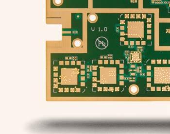
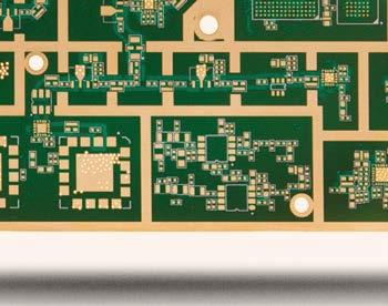
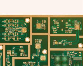
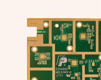
Today, RF circuitry is crammed into a large variety of commercial products. Most of these are handheld wireless devices for medical, industrial and communications applications. NCAB’s Harry Kennedy explains what to keep an eye on when designing the circuit boards.
Harry Kennedy
Credit: NCAB
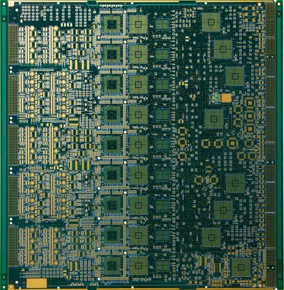
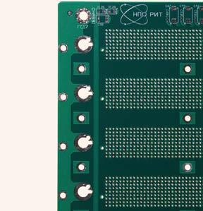
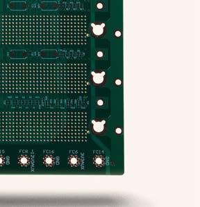
The RF frequency range is usually from 300 kHz to 300 GHz, with microwave being anything above 300 MHz. ere’s a considerable di erence between RF and microwave circuitry versus typical digital and analog circuits. In essence, RF signals are very high-frequency analog signals. erefore, unlike digital, at any point in time, an RF signal can be at any voltage and current level between the minimum and maximum limits. Moreover, a single band of signal can be very narrow or very wide and carried upon a very high-frequency carrier wave.
RF PCB design is also very much di erent and di cult, compared to high-speed digital-signal board design. When handling RF boards, there are many new challenges for PCB designers.
Challenges
First, RF is far more sensitive to noise, incurring ringing and re ections, which must be treated with great care. e noise can be dealt with by properly terminating the signal, thereby solving the ringing and re ection issues. Another method is to optimize the return path with proper ground.
Second, impedance matching is extremely critical for RF. e higher the frequency, the smaller the tolerance. Practically, if the total length of the trace from the driver to the receiver is greater than 1/16th of the wavelength of the signal, impedance control of that trace is required – 1/16th of the wavelength is called the signal’s critical length. If you’re routing a 1 GHz signal and its total length is greater than 425 mils, that trace needs to be impedance controlled. For example, 50 ohms out from the driver, 50 ohms during transmission and 50 ohms into the receiver. ird, the return loss must be minimized. At very high microwave frequencies, the return signal takes the path of least inductance. As a result, without good PCB design, it will go through power planes, through the PCB’s multi-layers or take some other route, and it will no longer be impedance controlled. Ground planes underneath the signals are good at providing an impedance-controlled path. erefore, there should be no discontinuities in the plane underneath the signal all the way from the driver to the receiver. Ground planes help minimize not only ground loop currents but also RF leakage into circuit elements.
Fourth, crosstalk is a major issue in high-frequency designs. is is because crosstalk is directly proportional to the edge rates of the active line. In this case, the coupled energy from the active line will be superimposed on the victim line. When the board densities increase, the problem of crosstalk becomes more critical.
As a solution, always leave adequate space around the signal trace for smooth bends and isolation of the RF signal. Keep all the traces coming out of or going into the transmitter and receiver modules as small as possible. e high-speed signals should be routed as far apart as possible. e length that lines run parallel to each other should also be kept to a minimum. All these measures will reduce crosstalk. Other solutions include reducing the dielectric spacing between the line and its reference plane and introducing a co-planar
structure, where a ground plane is inserted between the traces. Terminating the line on its characteristic impedance can also reduce the crosstalk by as much as 50 percent.
Other losses
ere are other signal losses as well. ere’s the skin e ect loss, more speci cally the skin e ect loss on the trace of a signal. Dielectric loss is a companion since both can be created at extremely high frequencies, when electrons owing through a conductor bounce back and forth with the electrons on the FR4 PCB substrate, for example. During this interaction, some of the energy from the electrons owing through the conductor is transferred to the electrons on the FR4. Consequently, that energy is converted to heat and subsequently lost.
In such instances, for extremely high- frequency microwave circuits, it’s best to use polytetra uoroethylene Te on (PTFE). e dielectric constant value of FR4 ese laminates have a dissipation factor of can vary as much as 10 percent. is in around 0.001 – compared to 0.02 for FR4. turn causes the impedance to vary. High- Using gold body on RF circuits can also frequency laminates have more stable fregreatly reduce skin losses. quency properties. en there’s the dielec-
When using RF circuits, PCB designers tric constant value itself. When it comes need to consider the laminate properties, to microwave circuits, this value is tied to such as the dissipation factor and dielec- the size of the circuit elements, so designtric constant value and its variation. FR4 ers may be able to decrease the size of the has a higher dissipation factor than high- circuit by choosing a laminate with a higher frequency laminates like Rogers and Nelco. dielectric constant value. is means that insertion losses are much higher when using FR4. ese losses are also a function of frequency and will inalso a function of frequency and will in- top layer in a horizontal direction and on crease as the frequency rises. crease as the frequency rises. anti-interference for high-frequency PCBs, the bottom layer in a vertical direction. is will help reduce signal interference. Increasing copper on the ground layer is helpful, too. Packaging important signal traces can obviously improve the signal’s anti- interference ability. Of course, we can also package interference sources to avoid interference on other signals. For the layout of signal traces, avoid loops and use a chrysanthemum link instead. In the power section of integrated circuits, it’s important to bridge the decoupling capacitor. Make the RF signal 50 ohms and always lay out the RF rst. Last but de nitely not least, isolation is key.
Credit: NCAB
Tips
there are a couple of tips engineers can take to heart. First, use inner layers as power ground layers. is will have the e ect of shielding and even decreasing spurious inductance while shortening the length of the signal wire reduces cross-interference between signals. Turning the circuit layout 45 degrees will help reduce high-frequency signal emission and coupling. e shorter the layout length, the better, and the less the better for through holes. e layout between layers should be in a vertical direction, on the To create better designs and improve the top layer in a horizontal direction and on anti-interference for high-frequency PCBs, the bottom layer in a vertical direction. is will help reduce signal interference. Increasing copper on the ground layer is helpful, too. Packaging important signal traces can obviously improve the signal’s anti- interference ability. Of course, we can also package interference sources to avoid interference on other signals. For the layout of signal traces, avoid loops and use a chrysanthemum link instead. In the power section of integrated circuits, it’s important to bridge the decoupling capacitor. Make the RF signal 50 ohms and always lay out the RF rst. Last but de nitely not least, isolation is key.
Harry Kennedy is a eld application engineer Harry Kennedy is a eld application engineer at NCAB Group. at NCAB Group.
Edited by Nieke Roos


